50257 - united states environmental protection agency
TRANSCRIPT

50257
1.3.7 Standard Operating Procedure — Conduct Soil-Gas Survey
Purpose: To ensure acceptable, consistent soil-gas samplingand on-site analysis for VOCs.
Pi scuss ion: Soil-gas surveys will be used to delineate theareal extent of VOC contamination of the CSG site resultingfrom groundwater and vadose zone contamination. Results willbe used to identify the source(s) of VOCs present in the soil,which may, in turn, indicate the source of these compounds inthe groundwater.
A soil-gas survey is not a substitute for monitoring wells butwhen properly performed, and under the appropriate conditions,soil-gas survey results can be used to direct placement ofmonitoring wells based on the distribution of VOCconcentrations in soil vapors.
The method involves pumping a small amount of soil-gas out ofthe soil matrix through a collection tube driven approximately2 feet into the ground, collecting soil-gases in a tube filledwith absorbents, and analyzing the desorbed gases for thepresence of VOCs through gas chromatography (GC) (Figure1-28). The depth of collection will be recorded in the fieldnotebook.
The soil-gas survey at the CSG site will consist of an overallarea extending approximately 500 feet northeast, northwest,southwest, and southeast from the CSG building (see Figure1-29). Probe installation will begin on the southeast side ofthe CSG building where the probable leaking tank was formerlyburied. Grid spacing will be every 50 feet within 100 feet ofthe building, where possible. Beyond 100 feet, the grid spac-ing will enlarge to every 100 feet, except where buildings,roads, or buried pipes and lines are located.
The soil-gas survey will extend outward from the CSG buildinguntil three successive probes yield no evidence of organicvapors. When three successive samplings are "clean" fororganic vapors, it will be assumed that any contamination fromCSG is not trackable beyond that point. That line could thenbe terminated.
A total of approximately 300 points are estimated to be sampledat or near the CSG site in this manner. If a point falls on abuilding or road, the point will be moved slightly (and so re-corded) or eliminated (and so recorded).
Soil-gas from each grid point will be evacuated through acopper/Teflon probe using a battery-powered air pump and Teflontubing. A sample of soil-gas will be obtained through a glasssampling bulb after a suitable purging time. The sample willbe transported to the trailer-based field labcgrBtftoeyn 3^3analyzed within 30 minutes of collection.
1.3-246133B

Hole Drivenby "Slam-Bar"
Sample Flask
Copper Tubefor InsertionOnly Ground
RubberStopper
Approximately24"
Removable Plug to KeepSoil Out During Insertion
3 n n 3 nFIGURE 1-28 SOIL GAS SURVEY PROBES
1.3-25

GW-2
-0-GW-3
General WashingtonCountry Club
GW
250 500
Scale in Feet
LegendFormer Leaking| Underground Storage
Tank Location0 Public Supply WellO Monitor Well
Irrigation WellSoil Gas Survey100'x 100'Grid50' x 50' Grid
FIGURE 1-29 PROPOSED SOIL-GAS SURVEY AT THE CSG SITE
1.3-26

SoiI-Gas Analysis
The field laboratory proposed will be eguipped with either aVarian 3600 GC eguipped with dual electron capture detectors,or a Hewlett Packard GC detector.
The soil-gas samples will be analyzed for tetrachloroethene,trichloroethene, 1,1,1-trichloroethane and 1,2-dichloroethene.
The analytical QA/QC will follow laboratory QA/QC proceduresfor gas chromatography. In addition, guantification of theanalytes will be accomplished by the external standard method,with calibration check standards run at least two times daily.Every twenty-fifth sample will be run in duplicate. Air blankswill also be run daily to check for and minimize contamination.
Procedures: See Appendix C.
1R3003061.3-27
6133B

APPENDIX C
GENERAL SOIL-GAS SAMPLING AND FIELD CHEMICAL ANALYSIS
fiR3003076133B

APPENDIX C
GENERAL SOIL-GAS SAMPLING AND FIELD CHEMICAL ANALYSIS
C.1 Associated Procedures
Appendix Appendix Title
C.2
MPN
General Instructions for Field PersonnelGuide to Handling & Packaging, of SamplesGeneral Eguipment Decontamination
PREPARATION
C.2.1
a.
C.2. 2
a.
b.
c .
d.
e.
C.2. 3
Factors
Office
Coordinate site access and obtain appropriatepermission.
Field
Stake location of utilities (client responsibility) .
Stake the location of the proposed sampling points.
Clear the working areas of all brush and minorobstructions, if necessary.
Decontaminate all sampling equipment by drawing cleanair through the sampling flasks for at least 10 min-utes and heating to drive off VOCs before the initia-tion of sampling and between samplings.
Measure the length of the probe for determination ofdepth of sample.
Factors That Affect Soil-Gas and Their Solutions
Several factors influence the distribution (may be due toadvection, adsorption, degradation, etc.) of VOCs through thesoil pore spaces of the vadose zone. These factors include thepermeability of the soil, blockage of the pore space within thevadose zone, chemical/physical properties of the VOCs, anddegradation. These factors are described in detail as follows:
C-l6133B

• Soil Properties — Soil properties including soilpermeability, soil density, effective porosity, andorganic carbon content will affect the VOCs transportin the unsaturated soil system. The soil permeabilitydetermines the diffusion of VOCs within the soil-gas.VOCs diffuse through the soil pore space from areas ofhigh concentration to areas of low concentration.VOCs will migrate farther and faster in sandy soilsthan they will in less-permeable silty or clayeysediments. Soil density, effective porosity, andorganic carbon content will determine the adsorptioncoefficients of VOCs between the solid phase and theaqueous phase. These coefficients describe thehydrophobia characteristic of VOCs and affect the VOCstransport in the vadose zone.
• Blockage of the Soil — Heterogeneity that "blocks"the permeability of the soil will slow down thediffusion of VOCs within the soil-gas in the vadosezone. Clay layers, moisture content, perched water,and caliche deposits all can block or partially blockthe pore spaces, and thus affect diffusion of the VOCswithin the vadose zone.
• Chemical/Physical Properties — The chemical/physicalproperties of the VOCs that affect diffusion throughsoil-gas include: Henry's Law constant, vaporpressure, octanol-water partitioning coefficient,reactivity, and polarity. In other words, the morevolatile compounds with higher partitioning to thevapor phase will transport farther and more rapidlythan the less volatile compounds with lowerpartitioning.
• Degradation — Degradation can affect the movement ofVOCs in the vadose zone. Biodegradation and oxidationcan degrade the organics and prevent substantialmigration due to diffusion.
Their Solutions
Because of the many factors that affect soil-gas diffusion,soil-gas surveys must be carefully designed and executed andproperly interpreted. In order to properly conduct a study andtrouble shoot the aforementioned factors, the followingsolutions are offered:
Factor Solution
Homogeneous, low- Probes must be spacedpermeability soil sandy soils.(silts and clays)
C-26133B
Factor Solution
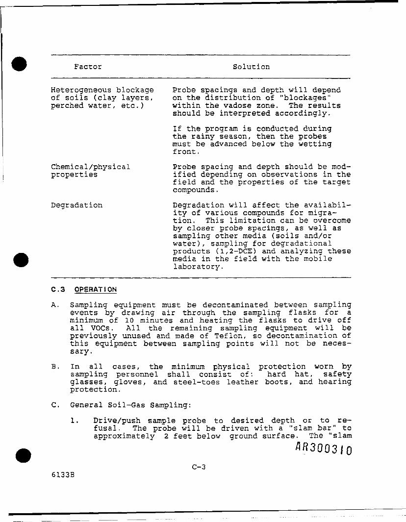
Heterogeneous blockage Probe spacings and depth will dependof soils (clay layers, on the distribution of "blockages"perched water, etc.) within the vadose zone. The results
should be interpreted accordingly.
If the program is conducted duringthe rainy season, then the probesmust be advanced below the wettingfront.
Chemical/physical Probe spacing and depth should be mod-properties ified depending on observations in the
field and the properties of the targetcompounds.
Degradation Degradation will affect the availabil-ity of various compounds for migra-tion. This limitation can be overcomeby closer probe spacings, as well assampling other media (soils and/orwater), sampling for degradationalproducts (1,2-DCE) and analyzing thesemedia in the field with the mobilelaboratory.
C.3 OPERATI ON
A. Sampling equipment must be decontaminated between samplingevents by drawing air through the sampling flasks for aminimum of 10 minutes and heating the flasks to drive offall VOCs. All the remaining sampling equipment will bepreviously unused and made of Teflon, so decontamination ofthis equipment between sampling points will not be neces-sary.
B. In all cases, the minimum physical protection worn bysampling personnel shall consist of: hard hat, safetyglasses, gloves, and steel-toes leather boots, and hearingprotection.
C. General Soil-Gas Sampling:
1. Drive/push sample probe to desired depth or to re-fusal. The probe will be driven with a "slam bar" toapproximately 2 feet below ground surface. The "slam
C-36133B

bar" will be withdrawn and the copper tube containingthe new Teflon tube sampling line will be insertedinto the hole up to the rubber stopper on the coppertube. The hole will be packed around the coppertube. The Site Manager or appointed representativeshall determine if soil gases will be collected fromthe point of refusal or if another attempt will bemade adjacent to the first location.
2. Collect sample by drawing a portion of the soil vaporsinto a decontaminated collection bottle using abattery-operated pump. Soil vapors will be drawnthrough the sample bottle for approximately three tofive volumes .of the "hole driven by the "slam bar"before the stopcocks are closed for the actual samplecollection.
3. Remove sample probe.
4. Complete and record all field observations, includingdepth of sample, in the field book whenever a sampleis collected.
5. A duplicate sample will be collected for every 25thsample.
Sample Analysis:
The samples are being analyzed on-site in a mobilelaboratory. The following criteria shall apply:
1. The gas chromatograph will be eguipped with a detectorthat is sensitive to TCE, tetrachloroethene, 1,1,1-trichloroethane and 1,2-dichloroethene contaminants.The use of electron capture and flame ionization de-tectors will be necessary.
2. As appropriate, a chromatograph column will be usedbased on sensitivity required, i.e., megabore,capillary.
3. Analysis will include laboratory blanks consisting of"pure" carrier gas (two per day).
4. Analysis will include external standards appropriateto the contaminants and field concentrations (two perday).
5. Analysis will include a field blank collected bydrawing ambient air through the sample collection Iequipment as if it were soil-gas (two pea dayX. ~ . I
6. Replicate analyses will be run every 25 samples.
C-46133B

7. Chromatograms must be visually inspected for errorsthat may affect the validity of the data. A sample ofparticular component may be eliminated from considera-tion on the basis of visual judgment. Examples ofelimination criteria include badly skewed or tailingpeaks, failure of the integrator to properly separateclosely eluting or tailing peaks, the presence oftransient peaks which mask or interfere with properguantitation of a peak of interest, etc. Notes shouldbe made directly on the chromatogram as to the reasonfor the elimination of a data point or run by atrained analytical chemist.
8. Appropriate readings and field and analytical labora-tory results will be entered on the soil-gas samplinganalysis and QA procedures. Associated information onlaboratory blanks, standards, field blanks, and repli-cates will be recorded in a soil-gas lab notebook anddelivered to the Site Manager.
C.4 POST OPERATION
C.4.1 Fie l d
Decontaminate all equipment as noted in Section C.3.A.
Using best reasonable efforts, return site to its originalcondition.
C.4.2 Office
A. Give the original forms to the Site Manager foreventual delivery to CSG and EPA.
C.5 References
Hydro Geo Chem, Inc., "Soil Gas Sampling, Analysis and QAProcedures," Tucson, Arizona, January 15, 1987.
Marrin, Donn L. , and Glenn M. Thompson, "Gaseous Behavior ofTCE Overlying a Contaminated Aquifier,". Groundwater, Vol. 25,No.l, pp. 21-27, 1980.
Marrin, D.L., H.B. Kerfoot, Lockheed, "Soil Gas Surveying forSubsurface Organic Contaminants," Las Vegas, Nevada, October22, 1986.
Tracer Research Corporation, Service Literature, Tucson,Arizona, 1985.
48300312C-5
6133B

1.3.8 Standard Operating Procedure — D r i l l Soil Borings andInstall Vapor Probes
Purpose: To ensure acceptable procedure for soil boring andinstallation of vapor probes at and near the CSG site so thatcontaminant migration and remediation can be efficiently andeffectively addressed.
Discussion: The boring process should not (to the extentpracticable) alter the medium that is being investigated.
Methods to be used for soil boring will be either hollow-stemaugers or air rotary. Additional information concerning boringtechniques is contained in Appendix H, Soil Boring.
Soil sampling is necessary around the CSG facility to determinethe approximate extent that VOCs may have migrated along thetop of bedrock. Placement of those borings (Figure 1-30) willbe based on the topography of the bedrock surface (see Figures1-8, 1-9, and 1-10, cross-sections) and the results of thesoil-gas survey. The soil borings will be drilled with a de-contaminated auger rig, with the augers preceded by a split-spoon sampling device. Split-spoons will be taken continuouslybelow 5 feet to the top of bedrock. The use of a continuoussoil corer may be substituted for split-spoon sampling if theequipment can be obtained without disrupting the schedule.
A description of the recovered soil will be recorded in thegeologists' field notebook for later compilation. The lastsplit-spoon collected before bedrock will be sampled and sentfor VOC analysis to determine whether a contaminant layer couldbe flowing along the bedrock surface. Once the split-spoon andaugers are removed, a 2-inch PVC screen and casing will be setin the borehole using standard monitoring well installationpractices (Figure 1-31). Installed in this fashion, thoseprobes can be used to measure water levels in the overburdenduring wet periods and VOC levels in soil-gas during dryperiods. It is anticipated, that up to 15 soil borings andprobes will be placed at various locations around the CSG site.
At present, data gaps for top-of-bedrock elevation and soilcharacteristics are on the southeast side of the site, alongthe TRANSCO pipeline, north of the CSG site, and along the golfcourse. Results of the soil-gas survey will be used as a guidefor exact placement of the borings/probes.
Procedures: See Appendix D.
AR3003I3
1.3-286133B

General WashingtonCountry Club
LegendFormer LeakingUnderground StorageTank LocationPublic Supply Well
O Monitor WellItriaation Well
Scale in Feet probe Proposed Locations
FIGURE 1-30 PROPOSED LOCATIONS OF SOIL BORINGS/VAPOR PROBESAT THE CSG SITE
1.3-29

Vent HoleLocking Cap
Ground Surface
Overburden
Approx. 2'X Bentonite
Grout
y2' Bentoniter Seal
2" DiameterPVC Pipe
Gravel Packto 1 Foot
Above Screen
Approx. 5' - 2& :=:g£ ___ 10.s|ot'Screen
AR3003I5
FIGURE 1-31 VAPOR PROBE CONSTRUCTION DIAGRAM AT CSG SITE
1.3-30

APPENDIX D
SOIL BORING AND SOIL VAPOR PROBE INSTALLATION
6133B

APPENDIX D
SOIL BORING AND SOIL VAPOR PROBE INSTALLATION
D.1 ASSOCIATED PROCEDURES
D
D
Appendix
EM0NB Part 2P
.2 PREPARATION
.2.1 Office
Appendix Title
Collect Soil SamplesGeneral Instructions for Field PersonnelSample Control and DocumentationGeneral Eojuipment DecontaminationVapors with a Flame lonization DetectorGuide to Handling & Packaging of Samples
a. Ensure that:
1. Site access has been coordinated and writtenpermission has been obtained for traveling acrossprivate property.
2. Utility maps for the site and/or coordinates of boringlocations are available.
b. Study scope of work.
c. Obtain materials listed in the equipment checklist(Attachment 1).
d. Review associated SOPs.
e. Coordinate schedules/actions with CSG Project Coordinator.
D.2.2 Field
a. Stake location of utilities (client responsibility).
b. Stake the location of the proposed borings in areas thatare not traversed by utility transmission ways.
c. Clear the working areas of all brush and minorobstructions, as necessary.
AR3003I7D-l
6133B

d. Decontaminate all down hole drilling and sampling equip-ment, as well as the back of the drilling rig prior to ini-tiation of drilling, as described in Appendix N, GeneralEquipment Decontamination.
D.3 OPERATI ON
a. Decontaminate sampling equipment between sampling events asdescribed in Appendix N, General Equipment Decontamination.
b. Inventory all samples as specified in Appendix 0, SampleControl and Documentation.
c. Handle all samples as specified in Appendix P, Guide toHandling, Packaging, and Shipping of Samples.
d. Soil sampling and borehole logging must conform to AppendixE, Collect Soil Samples.
e. If field screening of samples for organic vapors is re-quired, conduct survey as described in Health and SafetyMonitoring of Organic Vapors with a Flame lonizationDetector.
f. The borings will be completed as vapor probes.
g. Ensure that the back of the drilling rig is free of anyleaking hydraulic lines. Surfaces must not be greased tothe point that excess grease could be discharged duringdrillng.
h. Work must be conducted in compliance with all regulationswith regard to drilling safety and underground utility de-tection. Staked boring locations will be moved if requiredby safety considerations.
i. Each operating drill rig shall have a designated individualresponsible for logging the samples, and preparing the bor-ing logs. However, more than one rig at a time may besupervised by a qualified individual.
j. Log the samples, prepare the boring logs and vapor probe ,sketches, and supervise probe installation. !
k. No dyes, tracers, or other substances shall be used or ^_ _;otherwise introduced into borings. j
1. If drilling fluids are required, maintain portable recircu- (lation tanks for accurate records of fluid loss. Any water jthat is added to the boring should be sampled for analysis.
D-26133B

m. If specified, air systems include an air line oil filter,frequently replaced, to remove essentially all oil residuefrom the air compressor. Describe in the field logbook airsystem manufacturer(s), model number, air pressures used,frequency of oil filter change, and evaluation of air linefiltering.
n. Split-spoon sampling will precede augers. Spoon descrip-tions will be carefully recorded in the field logbooks.The bottom of the last spoon sample will be saved for VOCanalysis immediately following the opening of the spoon.This will be done by immediately slicing the end of thebottom sample into a collection jar and capping it tightlywithout any delay.
o. All field measurements and comments shall be recorded inthe field logbooks. The letter designation "NA" for notapplicable or "NK" for not known shall be used in all blankspaces. If some steps or procedures are not performed asdescribed, the reason must be stated as is practicable inthe field log or submitted as an attachment.
p. During drilling, a daily detailed driller's report shall bemaintained and submitted by a qualified person, if request-ed by the Site Manager. The report shall give a completedescription of all formations encountered, number of feetdrilled, number of hours on the job, shutdown due to break-down, feet of casing set, and other pertinent data.
q. Vapor probe implacement shall be the installation of 2-in.PVC, Schedule 40 pipe. The lower 5-foot portion of theprobe will be screen (where possible) with an end cap andclean gravel pack surrounding the screen. The screenlength will be 5 feet unless the depth of the overburden issuch that 2 feet of bentonite seal with 1 foot of groutabove the seal cannot fit above the screen (see Table 1-1,overburden thickness). For these cases, the screen lengthwill be reduced accordingly. Screen slot size will be No.10 unless field conditions require the slot openings to beincreased or decreased. Gravel pack shall extend to 1 footabove the screen followed by 2 feet of bentonite seal. Aminimum of 2 feet of bentonite grout will be placed abovethe bentonite seal. The top of the vapor probe shall notextend more than 6 inches above ground surface and be cap-ped with a lockable cap. Flush-mounted caps will be in-stalled in parking lots.
r. The abandonment of any boring shall be in accordance withthe appropriate state regulations. Borings shall be sealedby grouting from the bottom of the boring or well to groundsurface. This shall be done by placing a tremie pipe tothe bottom of the boring and pumping grout bnpog-iin'ShJ.spipe until undiluted grout flows from the boring a gr(fund
D-36133B

surface. The grout or tremie pipe may be gradually with-drawn, as long as the end of the pipe is at least 10 feetbelow the ground surface. The grout shall consist of a neatcement with four pounds of commercial bentonite and approx-imately 7.5 gallons of water added per 94-pound bag ofcement. After the grout has set (about 72 hours) the con-tractor shall check the abandoned site for grout settle-ment. Any depression in the grout shall then be filledwith a grout mix as described above. Methods other thanthose set forth herein may be implemented as dictated byappropriate state and/or local agencies. No grout addi-tives shall be used except the 4 percent bentonite.
s. Safety equipment shall be specified by the Site Health andSafety Officer. However, in all cases, the minumum physi-cal protection worn by drilling personnel shall consist ofa hard hat, safety glasses, gloves, steel-toed leatherboots, and hearing protection.
D.4 POST OPERATION
D.4.1 Field
a. Decontaminate all equipment as noted in Appendix N, GeneralEquipment Decontamination.
b. Return site to its original condition using best reasonableefforts.
D.4.2. Office
a. If drilling wastes were stored, determine the appropriatedisposal based on laboratory analysis of soils from theborings.
b. Deliver original data forms to the Site Manager for eventu-al delivery to CSG and EPA.
D.5 REFERENCES
U.S. Department of Energy, Uranium Mill Tailings Remedial Action(UMTRA) SOPs, Uranium Mill Tailings Remedial Action Project Of-fice, Albuquerque Operations Office, Albuquerque, New Mexico.
Barcelona, M.J., J.P. Gibb, J.A. Helfrich, and E.E. Garske,Practical Guide to Groundwater Sampling, U.S. Government Print-ing Office, EPA/600/2-85/104, 1985.
EQUIPMENT AND SUPPLIES CHECKLIST (See following page)
AR300320
D-46133B

EQUIPMENT AND SUPPLIES CHECKLIST
ATTACHMENT 1
EQUIPMENT AND SUPPL J E3 CHECKLIST
_____ Sample tags
_______ Sampl-e containers
_____ -Appropriate.clothing
_____ Sprayer with clean water for dust control
_____ Appropriate field forms
_____ Any applicable licenses and permits
_____ Field notebook
_________ Camera and film
_____ Any additional supplies listed in AssociatedProcedures
_____ Associated procedures, as needed
flR30032|D-5
6133B

1.3.9 Standard Operating Procedure — Collection of SoilSamp Ies
Purpose: To describe the physical nature of the subsurfaceunconsolidated materials during split-spoon and auger drillingactivities. These samples will be collected to detect VOCs inthe soil above the bedrock.
Discussion: Prior to the start of the field drilling pro-gram, written permission will have to be obtained from propertyowners to enter onto and perform drilling activities on theirprivate property. All personnel involved in the management ofthe drilling program shall have exchanged information as to ex-pected site geologic and hydrogeologic conditions. At thistime, RISOP will be covered in detail.
At the CSG Site there will be approximately 15 soil borings,(for locations see Figure 1-32), and up to 12 monitoring wells(see Figure 1-33). The monitoring wells may be installed assingle units or in clusters with 3 wells per cluster consistingof a shallow overburden well, a shallow well, and a deep moni-toring well. The locations of these clusters and wells willpartially be determined by the results of the soil-gas surveyas well as by historical groundwater data and the results ofthe groundwater modeling. For preliminary locations, see Sub-sections 1.3.5 and 1.3.10.
The soil borings and the drilling of the unconsolidated portionof the monitoring wells will utilize the procedure of contin-uous split-spoon sampling to the top of bedrock. Each of thesplit-spoons will be observed by the field geologist during theactual collection for driller adherence to proper method • ofhealth and safety practices. The field geologist will thencollect the spoon and scan the collected soil with the healthand safety instrument (OVA). Readings from the instrumentswill be noted in the field notebook.
It is planned that 15 VOC samples will be collected, one fromeach soil boring. After instrument readings have been record-ed, it will be the decision of the field geologist to sample aportion of the spoon that has an instrument reading of 5 unitsover background, within 10 seconds of the reading or quicklydescribe the soils classification into the field notebookbefore extracting the sample. In either case, the geologistwill thoroughly describe the soil collected in the split-spoonin the field notebook. Field notes will later be transcribedonto the soil boring forms described in Appendix E. Soils notcollected for analysis will be placed in drums supplied fordisposal of hazardous waste.
Following the description of soils and the coll ess: toi iip] -ip6 ream-pies for analysis, the split-spoons and collect ran scodpS' '-willbe thoroughly decontaminated as stated in Appendix N. Continu-ous split-spoon collection will continue to the top of bedrock.
1.3-316133B

• •GW-2
•0GW-3
•0-GW-1
General WashingtonCountry Club
LegendFormer LeakingUnderground StorageTank Location
• Public Supply Well.... . . O MonitojWeJI.
500
Scale in Feet ^V^ " <C ® Soil Borings/Vaporscale m Feet N N Probe Proposed Locations
FIGURE 1-32 PROPOSED LOCATIONS FOR SOIL BORING SAMPLES, CSG SITE1.3-32

GW-2T
-0-GW-3
General WashingtonCountry Club 1
MOS-15*
CSG ,, . .Former Tank
VFCC-2
LegendFormer Leaking
• Underground Storage TankLocation
^ Public Supply WellO Monitor Well\p- Irrigation Well-0- Abandoned Well. Cluster (Deep, Shallow** and Overburden)
FIGURE 1-33 POSSIBLE LOCATIONS FOR MONITORING WELLS AT CSG SITE
1.3-33

The soil sample immediately above bedrock will be collected foranalysis in all the soil borings. The geologist will decidewhether to sample any additional intervals which produced ahigh OVA reading. The soil samples will each be analyzed forVOCs. Twenty-five percent of the samples will also be analyzedfor TCL/TAL (target compound list/target analyte list). Atleast one TCL/TAL sample will be collected near the formerleaking tank area and. two TCL/TAL samples will be collectedalong Adams Avenue, with one of these near the drainage ditchadjacent to the French drain air stripper. The fourth samplecollection point will be based on field conditions.
Samples will be retained for engineering purposes, i.e., to beused in any analyses required in the design of a remediationprogram.
AR300325
1.3-346133B

APPENDIX E
SOIL AND ROCK BOREHOLE LOGGING AND SAMPLING
"R3003266133B

APPENDIX E
SOIL AND ROCK BOREHOLE LOGGING AND SAMPLING
E.1 ASSOCIATED PROCEDURES
Appendix
B
M
0
P
N
Appendix Title
Water Level Measurement
General Instructions for FieldPersonnel
Sample Control and Documentation
Guide to Handling & Packagingof Samples
General Equipment Decontamination
E.2 PREPARATION
E.2.1 Office
a. Obtain materials listed in the equipment check list asgiven in Appendix M, General Instructions for FieldPersonnel .
b. Review the RISOP. The RISOP will have a map of thesite with proposed borehole locations and appropriateborehole identification.
c. Coordinate schedules/actions with CSG Project Coordi-nator .
d. Notify the analytical laboratory of sample types, num-ber of samples, and the approximate arrival date.
E.2. 2 Field
a. Inventory and label all samples as per Appendix O,Sample Control and Documentation.
b. When applicable, decontaminate all samplinprior to sampling a new borehole and/or the next sam-pie interval within the same borehole as per AppendixN, General Equipment Decontamination.
E-l6133B

c. Record the pertinent information in the logbook or theappropriate data form. Note field conditions, unusualsituations, and weather conditions.
d. Follow Appendix P, Guide to Handling & Packaging ofSamples.
E.3. OPERATI ON
a. The upper portion of both the Borehole Log (Soil and Rock)field forms are identical and deal primarily with the ad-ministrative functions of location, identification, date,depth and hole diameter, and secondarily with groundwaterlevels information. The following is the procedure forfilling out both forms:
1. Site Name.
2. Location ID — A letter-digit combination will be as-signed sequentially to each borehole, surface watermonitoring location, etc. where physical, chemical,and biological, measurements are taken.
3. Coordinates (ft): North/East — The coordinates re-fer to the horizontal location of the borehole. Atthe time of the field investigation the exact coordi-nate position of the borehole will not be known. Inthis case, NA must be placed in the two spaces pro-vided for on the form. This information will be pro-vided when the survey data comes in after the drillingprogram has been completed.
4. Ground Elevation — At the time of the field investi-gation, the exact ground elevation (above mean sealevel) of the borehole will not be known. In thiscase, "NA" must be placed in the space provided on theform. This information will be provided when the sur-vey data comes in after the drilling program has beencompleted.
5. Location Type — This line is for data processing per-sonnel only and no additional information needs to begiven on this line.
6. Driller Name —- Identification of the drilling companyresponsible for drilling a borehole.
7. Completion Date — The date when the borehole reachedtotal depth in the format: day, month, year (e.g., 31January 1987.
8. Diameter — Diameter of borehole in incheof inches.
E-26133B

9. Depth — Total depth of borehole in feet and tenths offeet.
10. Construction methods — The construction or drillingmethod used in the advancement of the borehole. Atable of various construction methods is given at thebottom of each borehole log form.
11. Location proximity — The location of the boreholewith respect to the property boundary.
12. Location Description — Description of the approximateborehole location in respect to some recognizable per-manent topographic or geographic location nearby.
13. Groundwater Levels — Depth to water should be record-ed when encountered during the drilling and then atleast one, if not more, water level measurement shouldbe made after drilling has been completed and theborehole left open or a piezometer and/or monitoringwell has been installed. Before taking water levelmeasurements see Appendix B, Water Level Measurement.
14. Logger Name — Name of the individual responsible forperforming field measurements, collecting samples orlogging samples.
b. Having completed the upper portion of the borehole log com-plete the borehole log (soil) form in its entirety.
1. Depth (ft) — The numerical designation which general-ly depicts lithologic soil boundaries. Each space isusually designated as being equal to 1.0 feet of depthbelow ground surface. Depths shall- be recorded on theborehole log (soil) in feet and fractions thereof(tenths). Note that computer entries for depths areonly accepted in feet and tenths of feet, not inches.
Conversion TableInches to Tenths of Feet
Inches Tenths of Feet
1 .082 .173 .254 .335 42e -so AR3003237 .588 .67
E-36133B

Conversion Table (continued)
Inches
9101112
Tenths of Feet
.75
.83
.921.00
2. Sample Interval — The designated starting and endingdepth of the appropriate sampling technique. The fol-lowing table summarizes common sample length intervals.
Sampling Device Sample Interval (Feet)
Split Spoon Test 1.5 or 2.0
If the designated sample is 1.5 feet split spoon test(SST) but in actuality the SST only penetrates 0.5 feet(or some length less than the sample interval) in 50blows per 6 inches or less (refusal blow count) thegraphical representation for the sample interval isstill 1.5 feet.
3. Sample Recovery — The numerical representation of theactual sample recovered by the respective samplingmethod.
4. Sample Retained — The numerical representation of ac-tual sample retained for future laboratory testing orsample storage. This number cannot be larger thanwhat the sample recovery number is. If no sample isrecovered, write "NR" for no recovery in the spaceprovided.
5. Sample Method — One character code to identify thesampling method employed to retain a subsurface soilsample. Sample types are listed below. The box inthe lower right hand corner of the Borehole Log (Soil)form lists the sample types.
Sample Types
A - Auger cuttingsS - 2 in. O.D. 1.38 in. I.D. drive sampleU - 3 in. O.D. 2.42 in. I.D. tube sample
E-46133B

6. Sample ID — Two-digit numbers assigned to ensure thatdata collected retains uniqueness from other data col-lected, when ambiguity is possible. Two primary casesof using the Sample ID are: 1) actual collection ofphysical samples (e.g., soil, water, etc.) and 2) datameasurements taken at the sample X, Y, and Z loca-tion. For example, multiple soil samples may be takenin the same borehole, or multiple measurements of agiven data type may be taken at the same topographicsurface location. For a given site, location, logdate, log depth, and measured parameter, the samples(or measurements) collected should be numbered sequen-tially to prevent duplicates.
7. Blow Count — The number of blows (blowcounts)required for each 6 inches of the 18 (or 24 inch) SPT.
8. Visual description — The soil description shall be inaccordance with the Burmeister Designation. Attach-ments 4 and 5 include checklists outlining minimumdescriptions of fine-grained and coarse-grained soils.Munsell color chart will be used for soils color.
c. The following describes the procedures and required infor-mation for completing the borehole log (soil) form.
1. Depth (ft) — See Subsection E.S.b.l. Depth of thethree deep wells will be approximately 100 feet belowthe soil-bedrock interface. The shallow bedrock wellswill be approximately 20 feet below the soil-bedrockinterface and the overburden wells will be to the topof bedrock.
2. Packer Test Interval — A graphical representationwhich denotes the bottom of the top packer and the topof the bottom packer by use of a solid line drawn inthe column.
3. Drilling Method — The drilling method could be, butis not limited to, hollow stem auger (HSA) drilling,conventional flight auger, air rotary.
4. Sample ID — See Subsection E.3.b.6.
5. Percent Core Recovery — This is a measure of coringefficiency. The total length recovered can be meas-ured and, when divided by the length of run, a per-cent recovery can be obtained. Record recovery ofcore to the nearest 5 percent. Sometimes it is possi-ble to determine where in the run core loss occurred.The following clues are sometimes present/1 p FV.n B rf"ging off during drilling, (2) intense fracturing rn
E-56133B

certain sections of core can possibly be correlatedwith rough, high vibrations during drilling, and (3)rolled and recut pieces of core.
6. Percent Drilling Fluid Recovery, — Volume of fluiilosses and the interval over which they occur, e.g.,"no fluid loss" means that no fluid was lost otherthan through spillage and filling the hole; "partialfluid loss" means that though a return was achieved,the amount of return was significantly less than theamount being pumped; and "complete water loss" meansthat no fluid returned to the surface during pumpingoperation. A combination of the field personnel andthe driller's opinions on this matter will result inthe best estimate. A crude but relatively effectiveestimate can be made by placing a calibrated stick inthe recirculation pit, followed by estimating the re-turn flow, and an estimate as to the volume of the pitat 1/2 to 1 foot interval on the stick. The pumpingrate can be obtained by measuring elapsed time towithdraw a specified volume from the pit without re-turn. After estimating the return flow, a percentagecan be obtained. Return flow can sometimes be crudelymeasured with a 5-gallon bucket.
A change in the fluid recovery rates must be record-ed. If the recovery is essentially the same for anentire core run, only one call per change is neces-sary. Record to the nearest 10 percent.
7. Spacing, — Describe spacing of discontinuities asclose, wide, etc. according to the following:
Spacing
(1)
(2)
(3)
(4)
(5)
More than6 feet
2-6 feet
8-24 inches
2-1/2 -8 inches
3/4 - 2-1/2
Foliation,or Flow Banding Symbol
Very thickly VT(bedded, foliated,or banded)
Thickly, T
Medium M
Thinly TN
Very thinly VTN
Descriptionfor
Very widely(fracturedor jointed)
Widely
Medium
Closely
very clo.j|£3
Symbol
(VW)
(W)
(M)
(C)
orm?E-6
6133B

Not common, but when encountered, the following shouldbe noted in the remarks column. In describing struc-tural features, describe soil mass as thickly beddedor thinly bedded in accordance with the above criteria.
8. Orientation of fractures, — This call is numericallyrecorded. A protractor should be a standard fielditem. Clear plastic ones work fine. Measure to thenearest 10 degrees. All measurements are referencedwith 0 degrees at horizontal. If fractures have apersistent orientation, record at start and repeatevery 5 feet in depth.
9. Condition, — The roughness and amount of in-fillingin the fractures. Examples of condition descriptionare: smooth, clean, rough, stained, etc.
10. Weathering, — Describe the degree of weatheringaccording to the following table:
Grade Symbol Diagnostic Features
Fresh F No visible sign of decomposition or dis-coloration. Rings under hammer impact.
Slightly SLW Slight discoloration inwards from openWeathered fractures, otherwise similar to "F".
Moderately MW Discoloration throughout. Weaker mineralsWeathered minerals such as feldspar decomposed.
Strength somewhat less than fresh rockbut cores cannot be broken by hand orscraped by knife. Texture preserved.
Highly HW Most minerals somewhat decomposed. Speci-Weathered mens can be broken by hand with effort or
shaved with knife. Core stones presentin rock mass. Texture becoming indistinctbut fabric preserved.
Completely CW Minerals decomposed to soil but fabricand structure preserved (Saprolite).Easily crumbled or penetrated.
Residual RS Advanced state of decomposition resultingSoil in plastic soils. Rock fabric and struc-
ture completely destroyed. Large volumechange.
CAUTION: Soft rock is not necessarily weathereSR UcWlr Jfor signs of alteration minerals, etc., whichindicate true weathering.
E-76133B

11. Lithology — Two-character code describing the litho-logic interval encountered during various subsurfaceexploratory investigations. Attachment 5 lists thegeologic lithology codes that are to be used.
12. Visual description — Other petrologic descriptorsthat aid in the classification of the soil. Informa-tion that may be included is:
1. Typical nameSand, silt, clay, or any of the appropriate names/descriptions included in Attachment 5
2. Grain sizeFine, Medium, or Coarse
3. StructureStratified, Laminated (varved), Lensed, or Homogen-eous (nonstratified)
4. ColorUse Munsell color chart
5. CementationWeak or Strong
6. Local or Geologic Name
d. The following describes the procedures for collecting thesoil sample.
1. VOC samples - Pack soil in a 125 ml jar leaving no jheadspace.
2. TCL/TAL samples - Collect a VOC sample as stated in jd.l.; pack soil into a 925 ml jar for organic anal- *yses; pack soil into a 925 ml jar for inorganic anal-yses . "I
E.4 POST OPERATION
E.4.1 Field |
a. Collect all samples, inventory and prepare them for ship-ment as per Appendix P, Guide to Handling and Packaging of ISamples and Appendix O, Sample Control and Documentation. I
b. Decontaminate all equipment as noted in Appendix N, General "iEquipment Decontamination. J
c. Make sure all boreholes are properly staked and that proper »borehole ID is readily visible on locatioifl K apji j 3:^ fallow Isurvey team to locate and survey in borehole location. -*
E-86133B
E.4.2 Office
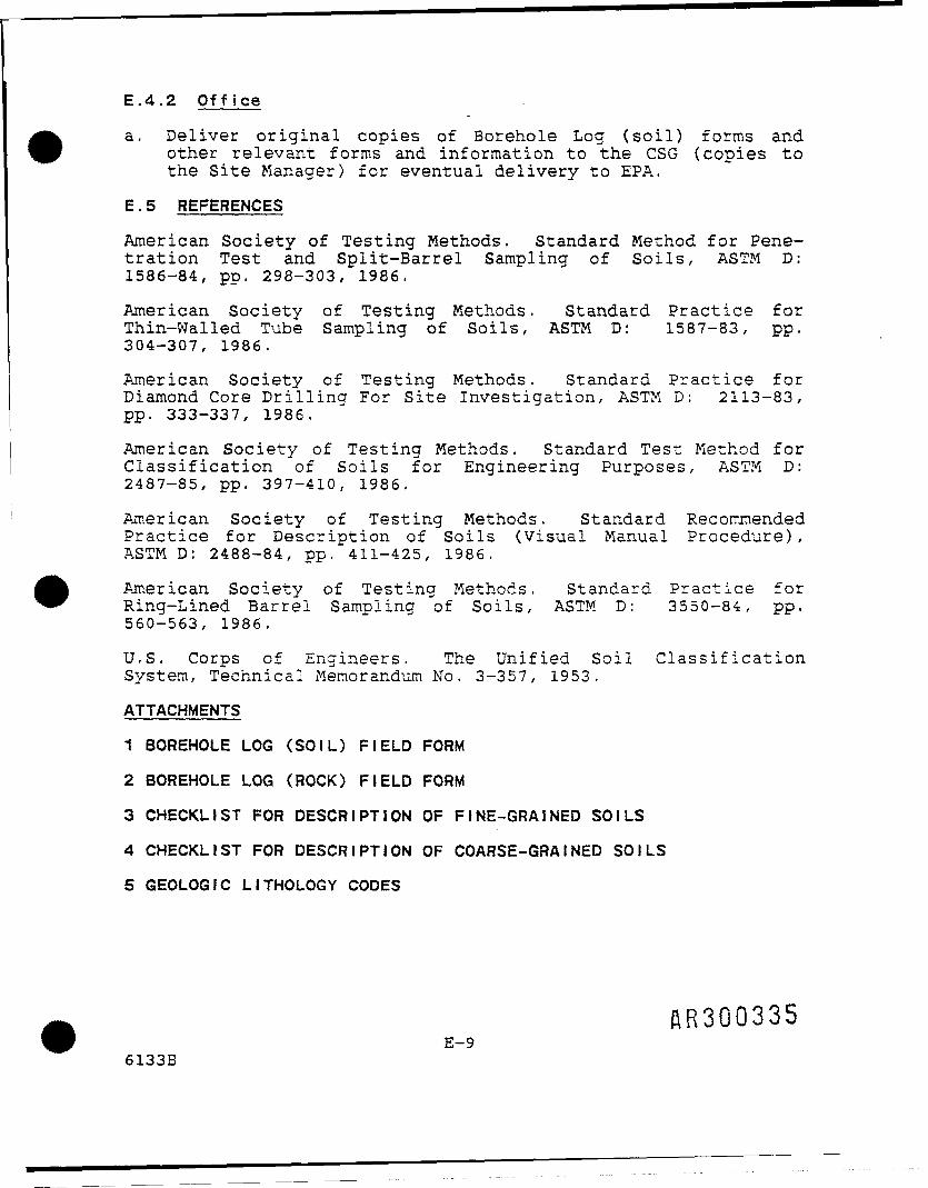
a. Deliver original copies of Borehole Log (soil) forms andother relevant forms and information to the CSG (copies tothe Site Manager) for eventual delivery to EPA.
E.5 REFERENCES
American Society of Testing Methods. Standard Method for Pene-tration Test and Split-Barrel Sampling of Soils, ASTM D:1586-84, pp. 298-303, 1986.
American Society of Testing Methods. Standard Practice forThin-Walled Tube Sampling of Soils, ASTM D: 1587-83, pp.304-307, 1986.
American Society of Testing Methods. Standard Practice forDiamond Core Drilling For Site Investigation, ASTM D: 2113-83,pp. 333-337, 1986.
American Society of Testing Methods. Standard Test Method forClassification of Soils for Engineering Purposes, ASTM D:2487-85, pp. 397-410, 1986,
American Society of Testing Methods. Standard RecommendedPractice for Description of Soils (Visual Manual Procedure),ASTM D: 2488-84, pp. 411-425, 1986.
American Society of Testing Methods, Standard Practice forRing-Lined Barrel Samoling of Soils, ASTM D: 3550-84, pp.560-563, 1986.
U.S. Corps of Engineers. The Unified Soil ClassificationSystem, Technical Memorandum No. 3-357, 1953.
ATTACHMENTS
1 BOREHOLE LOG (SOIL) FIELD FORM
2 BOREHOLE LOG (ROCK) FIELD FORM
3 CHECKLIST FOR DESCRIPTION OF FINE-GRAINED SOILS
4 CHECKLIST FOR DESCRIPTION OF COARSE-GRAINED SOILS
5 GEOLOGIC LITHOLOGY CODES
AR300335E-9
6133B

1
..
— .
DRILLING LOG
WELL NlLOCATIC
JMBER)N.
ATTArUMPMT 1SKETCH MAP
BORE HOLE (SOIL) FIELD FORM
OWNER:ADDRFSS
TOTAL DFPTH
3URFAC
DRILLINCSOMPANDRILLER
LOG BY
_ _
_ _
_ _
— -
- -
E ELEVATIOfv
Y
I WATFR I FVFI •
DRILLING DATE
^
' ASTM D1586
S~ » jS'
^ ^ ^ DESCRIPTION ' SOIL CLASSIFICATION* s (COLOR. TEXTURE, STRUCTURES)
R^no33
_ _ _ RHPFT OF

Locking Capand Padlock "-~-»<HCLl
SJ Vent Hole -
.- -_---.-.- •.-. -.-.-.-_-.-.---.-.-- _•_ . - - -_-
—— -^ f^ /\ /x /li\1
i!I!Ng>
:::"-:'.- Bedrock >..-.-:-;/:-::::: Unit ;::::>:-: -..'_• ..-_---..•_.-_-.-„-_-_-_-_-_- /
Bottom Cap — —
- - /--. /~ ~, •»«y
t
_
__ — . — _ i
-•'-
/.' Y,
6/./ /./.' /j/.4/ /;
/./ /.
// /.
/./. /J
<•
!-?-!EE EE •'
— — :.— — .;
— 1 ••''
~: ^ '•— — -
i
—— '
.-Protective Casing ..„ „,.. -jS . Pt'Ckiip
.. r ^ TraHir Part
* —— Dram Hole We" Development ————————————————s i SWGround SurfaceN\ss\\ss'\s\
\\s,\\\\\\
> *~" ~" — — Rnrphnlp piametpr .
^ ———————— Outer Casing Diameters> Material^ ——————— Rnrphnle- Diamfitpr
————— - —— Casing Diamptsr
Material1 Grout: Material/Mixture
Rettingi|1 Plug Material
Setting ,. ..' Ranripark- Material
; Gradation
\ Retting: • •'•. Screen Material
' Length _. .. ., . ... ... .. ,,._TypeOpening Si?e
-' Retting
' —— Coupling
t ——————— Sump 1 ength
j AR3003-
ATTACHMENT 2 BORE HOLE LOG (ROCK) FIELD FORM
E-ll

ATTACHMENT 3
CHECKLIST FOR DESCRIPTION OF FINE-GRAINED SOILS
1. Typical NameSandy Silt, Silt, Clayey Silt, Sandy Clay, Silty Clay,Clay, Organic Silt, Organic Clay, or Fill
2. Size DistributionApproximate percent gravel, sand and fines in fractionfiner than 3 inches.
3. ColorNote presence of mottling and banding, as well as soilcolor
4. Moisture ContentDry, Moist, Wet, or Saturated
5. ConsistencySoft, Firm (medium), Stiff, Very Stiff, or Hard
6. StructureStratified, Laminated (Varved), Fissured, Blocky,lensed, or Homogeneous (nonstratified). _ t
7. Cementation ^Weak, Strong, or Absent
8. Local or Geologic Name I
9. Group Symbol: _ j
Soil ClassificationGroup Symbol Group Name ,
CL Lean clay (low to medium 'plasticity)
Ml Silt |OL Organic clay or silt (lean) ICH Fat clay (high plasticity)MH Elastic silt >OH Organic clay or silt (fat) JPT Peat
HR300338 j
E-126133B

ATTACHMENT 4
CHECKLIST FOR DESCRIPTION OF COARSE-GRAINED SOILS
1. Typical NameSand, Clayey Sand, Silty Sand, Gravel, Clayey Gravel,Silty Gravel, Cobbles, or Boulders
2. GradationWell Graded (uniformly graded), or Poorly Graded (gap-graded)
3. Size DistributionApproximate percent gravel, sand, and fines in fractionsfiner than 3 inches.
4. Grain ShapeAngular, Subangular, Subrounded, or Rounded
5. Color
6. Moisture ContentDry, Moist, Wet, or Saturated
7. StructureStratified, Lensed, or Nonstratified
8. CementationWeak, or Strong
9. Local or Geologic Name
10. Group Symbol:
Soil ClassificationGroup Symbol Group Name
GW Well-graded gravelGP Poorly graded gravelGM Silty gravelGC Clayey-gravelSW Well-graded sandsSP Poorly graded sandsSM Silty sandSC Clayey sand
SR300339E-13
6133B

ATTACHMENT 5
GEOLOGIC LITHOLOGY CODES
LITHO-LOGICCODE
ALBABRBTCACGCHCL
CRCSDIDOFLGC
GM
GNG?
GRGW
GYLGLSMH
ML
NR
OHOL
OTPT
6133B
NAME/DESCRIPTION
ALLUVIUMBASALTUNDIFFERENTIATED BEDROCKBANDELIER TUFFCALCRETECONGLOMERATEFAT CLAYSLEAN CLAYS, SANDY CLAYS,OR GRAVELLY CLAYSCHERTCLAYSTONEDIORITEDOLOMITEFILL MATERIALCLAYEY GRAVEL OR CLAYEYSANDY GRAVELSILTY GRAVEL OR SILTYGRAVELLY SANDGNEISSGRAVEL OR SANDY GRAVELPOORLY GRADEDGRANITEGRAVEL OR SANDY GRAVELWELL GRADEDGYPSUMLIGNITELIMESTONEMICACEOUS SILTS ORDIATOMACEOUS SOILSSILTS, SANDY OR GRAVELLYSILTS, DIATOMACEOUSSOILS
NO RECOVERY OF DATA FORCLASSIFYING
FAT ORGANIC CLAYSORGANIC SILTS OR LEANORGANIC CLAYS
OTHER GENERAL MATERIALSPEAT, HUMUS AND OTHERORGANIC SOILS
MAJOR DIVISION(l)
———----
FINE GRAINED SOILSFINE GRAINED SOILS
----—--—
COARSE GRAINED SOILS
COARSE GRAINED SOILS
—COARSE GRAINED SOILS
--COARSE GRAINED SOILS
------
FINE GRAINED SOILS
FINE GRAINED SOILS
--
FINE GRAINED SOILSFINE GRAINED SOILS
--PEAT & ORGANIC SOILS
E-14
MAJOR DIVISION(2)
———
-—--
HIGH PLASTICITY SOILSLOW PLASTICITY SOILS
--———--
GRAVEL & GRAVELLY SOILS
GRAVEL & GRAVELLY SOILS
—GRAVEL S GRAVELLY SOILS
--GRAVEL & GRAVELLY SOILS
_----
HIGH PLASTICITY SOILS
LOW PLASTICITY SOILS
--
HIGH PLASTICITY SOILSLOW PLASTICITY SOILS
--PEAT & ORGANIC SOILS
^30031*0
i-
_==,
»4
- —
- ——— .
i
LI*1
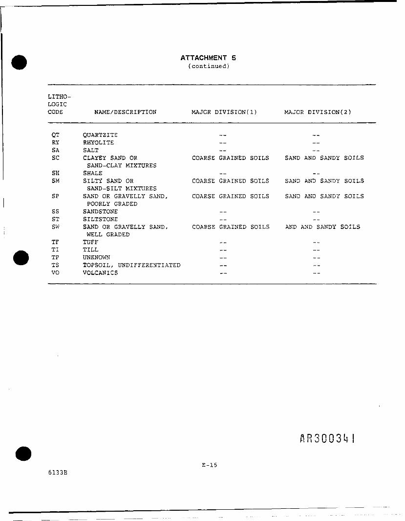
ATTACHMENT 5(continued)
LITHO-LOGICCODE
QTRYSASC
SHSM
SP
SSSTSW
TFTITPTSVO
NAME/DESCRIPTION MAJOR DIVISION(l)
QUARTZ I TERHYOLITESALTCLAYEY SAND OR COARSE GRAINED SOILSSAND-CLAY MIXTURESSHALESILTY SAND OR COARSE GRAINED SOILSSAND-SILT MIXTURESSAND OR GRAVELLY SAND, COARSE GRAINED SOILSPOORLY GRADEDSANDSTONESILTSTONESAND OR GRAVELLY SAND, COARSE GRAINED SOILSWELL GRADEDTUFFTILLUNKNOWNTOPSOIL, UNDIFFERENTIATEDVOLCANICS
MAJOR DIVISION{2)
__----
SAND AND SANDY SOILS
--SAND AND SANDY SOILS
SAND AND SANDY SOILS
----
AND AND SANDY SOILS
----------
AR3003M
E-156133B

1.3.10 Conduct Ecological Assessment
This task has been deleted from the RI by EPA. Should theresults from this RI indicate the need for an EcologicalAssessment, CSG will perform this task if required by EPA.
AR30Q3U21.3-35
6134B

APPENDIX F
(To be included later, if specified by EPA)
flR3003l*36134B

1.3.11 Standard Operating Procedure — S o i l Sample Analysis
Purpose
To analyze the soil collected from soil borings for volatilehalogenated organic compounds and target compounds and targetanalytes (TCL/TAL).
Discussion
Method 8010 provides gas chromatographic conditions for detec-tion of halogenated volatile organic compounds in solid materi-als. Table 1-12 indicates compounds that may be analyzed bythis method and lists the method detection limit for each com-pound in reagent water. Table 1-13 lists the practical quan-titation limit for other matrices. Samples can be analyzedusing purge-and-trap (Method 5030). A temperature program isused in the gas chromatograph to separate the organic com-pounds. Detection is achieved by a halogen-specific detector(HSD).
The 8010 method provides an optional gas chromatographic columnthat may be helpful in identifying the analytes from interfer-ences that may occur and for analyte confirmation.
The four soil samples collected for TCL/TAL evaluation will beanalyzed using standard CLP methods.
Interferences
Samples can be contaminated by diffusion of volatile organics(particularly chlorofluorocarbons and methylene chloride)through the sample container septum during shipment and stor-age. A field sample blank prepared from reagent water and car-ried through sampling and subsequent storage and handling canserve as a check on such contamination. Appendix G describesthe components and analytical standards associated with the gaschromograph system.
Gas chromatograph•
An adequate analytical system provides purge-and-trap sampleintroduction and all required accessories, including detector,analytical columns, recorder, gases, and syringes. A datasystem with the capability of measuring peak heights and/orpeak areas is recommended.
Columns:
Column 1: 8 f t x 0.1 in I.D. stainless steel or glass columnpacked with 1 percent SP-1000 on Carbopack-B 60/80 mesh or
eguivalent' AR3003IA1.3-36
6134B

Table 1-12
Chromatographic Conditions and Method Detection L i m i t sfor Halogenated V o l a t i l e Organics
Compound
Bromodichlorome thaneBromoformCarbon tetrachlorideChlorobenzeneChlo roe thaneChloroform2-Chloroethyl vinyl etherChlorome thaneDibromochlorome thane1, 2-Dichlorobenzene1, 3-Dichlorobenzene1,4-Dichlorobenzene1,1-Dichlo roe thane1, 2-Dichloroethane1, 1-Dichloroethenetrans-1, 2-Dichloroethene1, 2-Dichloropropanetrans-1, 2-Dichloropropylene1,1,2, 2-TetrachloroethaneTetrachloroethylene1,1, 1-Trichloroethane1, 1, 2-TrichloroethaneTrichloroetheneTrichlorof luorome thaneVinyl chloride
•
Retention(min)
Col. 1
13.719.213.024.23.3310.718.01.50
16.534.934.035.49.30
11.48.010.114.915.221.621.712.616.515.87.182.67
time
Col. 2
14.619.214.418.88.6812.1
5.2816.623.522.422.312.615.47.729.3816.616.6
15.013.118.118.1
5.28
Methoddetectionlimita(ug/L)
0.100.200.120.250.520.050.130.080.090.150.320.240.070.030.130.100.040.34
0.030.030.020.12
0.18
aUsing purge-and-trap method (Method 5030)
1.3-376134B
flR3003t*5

Table 1-13
Determination of Practical Quantisation Limits (POL)for Various Matrices3
Matrix Factor*3
Groundwater 10Low-level soil 10Water miscible liquid waste 500High-level soil and sludge 1250Non-water miscible waste 1250
aSample PQLs are highly matrix-dependent. The PQLs listedherein are provided for guidance and may not always beachievable.
bPQL = [Method detection limit (Table 1-11)] X [Factor (Table1-12)]. For non-aqueous samples, the factor is on a wet-weightbasis.
AR3003l*61.3-38
6134B

Column 2: 6 f t x 0.1 in I.D. stainless steel or glass columnpacked with chemically bonded n-octane on Porasil-ClOO/200 mesh(Durapak) or equivalent.
Detector: Electrolycic Conductivity (HSD)
• Sample introduction apparatus: Refer to Method 5030for the appropriate equipment for sample introductionpurposes.
• Syringes: 5-ml Luerlok glass hypodermic and a 5-mL,gas-tight with shutoff valve.
• Volumetric flask: 10-, 50-, 100-, 500-, and 1,000-mLwith a ground—glass stopper.
Microsyringe: 10-, 25-uL with a 0.006-in I.D. needle(Hamilton 702N or equivalent) and a 100-uL.
Reagents
Reagent water: Reagent water is defined as a water in which aninterferent is not observed at the method detection limit (MDL)of the parameters of interest.
Stock standards: Stock solutions may be prepared from purestandard materials or purchased as certified solutions. Stockstandards are prepared in methanol using assayed liquids orgases, as appropriate.
Secondary dilution standards, which are prepared using stockstandard solutions, should consist of analyte concentrationssuch that the aqueous calibration standards will bracket theworking range of the analytical system.
Calibration standards at a minimum of five concentration levelsare prepared in reagent water from the secondary dilution ofthe stock standards. One of the concentration levels should beat a concentration near, but above, the method detectionlimit. The remaining concentration levels should correspond tothe expected range of concentrations found in real samples orshould define the working range of the GC. Each standardshould contain each analyte for detection by this method (e.g.,some or all of the compounds listed in Table 1-12 may beincluded).
Surrogate standards are used to evaluate both the performanceof the analytical system and the effectiveness of the method indealing with each sample matrix. Each sample, standard, andreagent water blank with surrogate halocarbons. A combinationof bromochloromethane, 2-bromo-l-chloropropane, and 1,4-di-chlorobutane is recommended to encompass the range of thetemperature program used in this method.
1.3-396134B

REFERENCES
1. Bellar, T.A., and J.J. Lichtenberg, J. Amer. Water WorksAssoc., 66(12), pp. 739-744, 1974.
2. Bellar, T.A., J.J. Lichtenberg, "Semi-Automated HeadspaceAnalysis of Drinking Waters and Industrial Waters forPurgeable Volatile Organic Compounds," in Van Hall, ed.,Measurement of Organic Pollutants in Water and Wastewater,ASTM STP 686, pp. 108-129, 1979.
3. Development and Application of Test Procedures for SpecificOrganic Toxic Substances in Wastewaters: Category 11 -Purgeables and Category 12 - Acrolein, Acrylonitrile, andDichlorodifluromethane. Report for EPA Contract 68-03-2635(in preparation).
4. U.S. EPA 40 CFR Part 136, "Guidelines Establishing TestProcedures for the Analysis of Pollutants Under the CleanWater Act; Final Rule and Interim Final Rule and ProposedRule, October 26, 1984.
5. Provost, L.P. and R.S. Elder, "Interpretation of PercentRecovery Data," American Laboratory, 15, pp. 58-63, 1983.
6. "EPA Method Validation Study 23, Method 601 (PurgeableHalocarbons)," Report for EPA Contract 68-03-2856 (inpreparation).
1.3-406134B
6134B
APPENDIX G
SOILS SAMPLE ANALYSIS
^300349

APPENDIX G
SOILS SAMPLE ANALYSIS
Refer to Method 8010 for detection of halogenated v o l a t i l eorganic compounds in solid materials, and CLP methods fordetection of organic compounds and inorganic compounds and
analytes in solid materials.
AR300350G-l
6134B

1.3.12 Standard Operating Procedure — Monitoring WellInstallat ion
Purpose: To provide the necessary number of data points fordetermining and monitoring groundwater conditions.
Discussion: Specifically, the objectives of the drilling andinstallation of the monitoring well network are to:
• Describe the overburden soil types and the subsurfacerock types, structure, stratigraphy, and degree offracturing.
• Provide information on the horizontal and verticalextent and direction of contaminant migration.
• Provide information on the rate and direction ofgroundwater movement.
• Provide information needed to develop a groundwaterflow model of the site that can be used to design aneffective groundwater remediation plan.
Three clusters of wells, including a deep bedrock well, ashallow bedrock well, and an overburden well, are planned inthe vicinity of the COS site (Figure 1-34). A fourth cluster,or partial cluster may be considered. The first cluster to bedrilled will be located structurally downdip of the site, tothe north-northwest. The second cluster is plannedstructurally along strike of the site, to the west-southwest,and the third is topographically down-gradient of the site, ina south-southeast direction. Where possible, the well clusterswill be located as close as possible to the lineamentsdiscussed in Subsection 1.1.9 and shown on Figure 1-13.
During the RI, data from the soil-gas survey and soil-boring/vapor probe installation program will be collected before thenew monitor wells are installed. Should interpretation ofthese data sets warrant modification of the location of the newwell clusters, EPA will be notified of the modification and thejustification for the change before installation of the moni-toring wells.
The construction plan for the overburden wells is to drill theborehole approximately l foot into the top of bedrock and set 2to 5 feet of PVC screen with attached riser in the borehole. A2-foot length of screen will be used only if the overburdenthickness is 4 feet or less (see Table 1-1) as allowances mustbe made for 2 feet of bentonite seal and 1 foot of grout. Theoverburden wells will monitor groundwater perched in theshallow unconsolidated zone down to and including theoverburden-bedrock interface. /}/??fifior-
1.3-416134B

GW-2T
•0-GW-3
General WashingtonCountry Club 1
MOS-15
Former TankOMOS-13,
OMOS-3
VFCC-2
LegendFormer Leaking
B Underground Storage TankLocation
0 Public Supply WellO Monitor Well" Irrigation Well<j> Abandoned Well• Cluster (Deep, Shallow* * and Overburden)
AR300352
FIGURE 1-34 POSSIBLE LOCATIONS FOR SOIL SAMPLES COLLECTED FROMMONITOR WELLS, CSG SITE
1.3-42

The shallow bedrock wells will be drilled at least 25 feet intocompetent bedrock. If borehole conditions are stable, screenswill not be necessary to complete the well. Otherwise, the topof the 20-foot PVC screen will be positioned at least 5 feetinto competent bedrock. These shallow bedrock wells willmonitor groundwater in the upper 20 feet of bedrock.
The deep bedrock wells will be constructed to monitor thegroundwater at a minimum depth of 80 feet below thesoil-bedrock interface, which will be a distinctly differenthorizon from that monitored by the shallow bedrock wells. Thethree deep wells will be cored. After coring, the annulus of awell will be widened to accomod.ate packers, and the well willbe geophysically logged to aid in assessing borehole integrity,correlating stratigraphy and locating water-bearing fractures.Packer-tests will then be conducted on several intervals ofeach deep well that has been cored. After packer-testing, thewell will be cased and completed as an open borehole orscreened well. Results from core evaluation, boreholegeophysical logging interpretation and packer tests will beintegrated to help delineate flow zones and thus ensure thatonly one flow zone is included in a screened interval. Thedeep wells will be drilled first so that stratigraphicinformation is available to help plan the shallower wells.
All monitoring wells will be continuously split-spoon sampledthrough the unconsolidated layer for one of the wells in eachcluster. Deep and shallow bedrock wells will be cased from atleast 5 feet into bedrock to the surface (see Figure 1-35).The change in drilling rate of penetration will indicate to thedriller where bedrock is encountered. The wells in eachcluster will be placed approximately 10 feet apart.
Casing and screen materials will be schedule-40 PVC or steel,4- or 6-inch ID, with end cap and locking well cap. Casing andscreen joints shall be welded or threaded together to form awatertight seal without the use of joint compound or grease.Whichever casing and screening material is chosen, thatmaterial will be consistent within each individual well andwill be used in all new well construction.
It is presently anticipated that screen slot size will be 0.020inches (20 slot). The sand will be packed from TD to 2 feetabove the top of the screen.
After installation of the monitoring well and. the "setting" ofthe bentonite grout, a minimum of 12 hours will be allowed topass before well development. Each well will be developed bypumping or surging till the discharge is reasonably clear. Thedischarge will be pumped to the local sewer treatment plant viathe local sewer system if possible. After development, a mini-mum of one week will be allowed to pass before sampling toallow the groundwater and well(s) to come to equilibAiftujji.Q Q3 5 3
1.3-436134B

a> oo ora "P£M 2T) O§ °.
I 1
\
\
V
<D'£Q"QJCD
\\A3 \1
CD uur
1
0 I "}
if1 /
\\ — .= T3 <0 \ C\ S c o> ® co > <u
f v ^—————————— r,....,,J
"V m ~V\ _ o T ) J t :3 re , co
X \ ( U < D \\ rn r/3 \
.i \u! QJ ^Sw g
jf ——— A^ ———— DC \1 1 1 1 1 1 1 1 1 1 1 1 1 P1! °co \ \
__....,...,..„, ^ill \ \ \It t , . .. J u y \
Sc c "o I \a> w <° CO \ \
f | H \ v fe!< \ \^ •1 yj 1~~ \ ( "5 \
\ \ \ X
Oeno
^ °Ioc
0-LUHIO
DC
B AR3003S
(O
ooUJCDOor
5'UJ
QC
ineo
UlE Ig Iu.
I

All cores will be marked and boxed for storage at the CSG sitefor the extent of the RI to be accessable for inspection by EPAand DER representatives. Before disposal, EPA will be given 30days written notice of CSG's intent to do so.
Procedure: See Appendix H.
6134B
AR3003551.3-45
APPENDIX H
MONITORING WELL INSTALLATION
6134B

APPENDIX H
MONITORING WELL INSTALLATION
H.1 Associated Procedures
Appendix
E
M
P
N
C ofPart 2
H.2 Preparation
H.2.1 Office
Appendix Title
Soil Sampling
General Instructions for Field Personnel
Guide to Handling, Packaging and Shipping ofSamples
General Equipment Decontamination
Health and Safety Monitoring of OrganicVapors with a Flame lonization Detector
a. Review associated procedures.
b. Coordinate schedules/actions with COS staff.
c. Coordinate site access; written permission is requiredfor drilling or traveling across private property.
d. Obtain up-to-date site map with well locations and alist of previous depth-to-water (DTW) measurements.Obtain the order in which DTWs need to be measured.
e. Obtain utility maps for the site and/or coordinateboring locations with utility companies or departments.
f. Research site hydrogeology to estimate key parameters(e.g., anticipated aquifer depth and thickness, typesof contaminants, etc.).
g. Obtain materials listed in the equipment checklist(Attachment 1).
H.2.2 Field
a. Stake location of utilities. A R 3 u U o J /
H-l6134B

b. Stake the location of the proposed borings in areasnot traversed by utility transmission ways.
c. The working areas are to be cleared of all brush andminor obstructions, as necessary.
d. Decontaminate all equipment before monitoring wellinstallation, as described in Appendix N, the GeneralEquipment Decontamination. All casing and screen willbe decontaminated by steam cleaning and air dryingbefore installation into the borehole.
e. Drilling fluids or grout will be required. Thesource(s) of any water to be used in grouting and wellinstallation must be approved by the site managerprior to field operations.
H.3 Operation
a. Obtain the anticipated number of solid and liquid55-gallon drums.
b. Samples must be handled as specified in Appendix P,Guide to Handling, Packaging and Shipping of Samples.
c. Rock sampling and borehole logging must conform to thespecifications defined in Appendix E.
d. If field screening of samples for organic vapors isrequired it must be conducted as described in theHealth and Safety Plan.
e. The back of the drilling rig must be free of any leak-ing hydraulic lines. Surfaces must not be greased tothe point that excess grease could be dislodged duringdrilling.
f. Work shall be conducted in compliance with any and allOSHA regulations with regard to drilling safety andunderground utility detection. Borings will berelocated if required by safety considerations.
g. Each operating drill rig shall have a designatedindividual responsible for logging the samples,preparing the boring logs and well sketches, and wellinstallation of that rig.
h. No dyes, tracers, or other substances shall be used orotherwise introduced into borings, wells, soil moist-ure (water) samplers, grout, backfill, groundwater, orsurface water. AR300358
i. Drilling fluids will be required. The use of drums orportable recirculation tanks are required.
H-26134B

j. Any use of solvents, glues, soap, or cleaners is pro-hibited below grade unless otherwise stated in thespecifications. Where it is used, such material shallbe described, to include manufacturer and type (speci-fication). Likewise, the use of pipe dope, grease,and oil is also prohibited.
k. Air systems must include an air line oil filter, fre-quently replaced, to remove essentially all oil resi-due from the air compressor. The usage of any airsystem shall be fully described in the driller's log.
1. The sampling interval and type of sampling equipmentspecified in the RISOP shall be adhered to unlessotherwise directed by the Site Geologist.
m. All field measurements and comments shall be docu-mented in the field logbook and on the Borehole Log(Rock) Field Form. All lines on the forms shall becompleted.
n. During drilling, a daily detailed driller's reportshall be maintained and submitted by a qualifiedperson if requested by the Site Manager. The reportshall give a complete description of formations en-countered, number of feet drilled, number of hours onthe job, shutdown due to breakdown, feet of casingset, and other pertinent data.
o. Rock coring (for deep wells only):
1. Casing shall be required for the full depth ofthe overburden in borings in which rock will becored.
2. The casing shall be advanced according to speci-fications in the RISOP. The casing shall be ofthe flush joint or flush couple type and of suf-ficient size to allow for soil sampling, coring,and/or well installation.
3. Drill rods for drilling rock should be NW in sizeto minimize vibration and chattering. Rock coresize shall be NX.
4. Core barrels shall be of the improved double-tubevarieties such as the Christensen Series C or Dmodels or equivalent, and shall be equipped witha split inner tube.
5. In general, 5-foot barrels will be employed atthe discretion of the Site Manager. nnonnor-^
AnJUU359H-3
6134B

6. Every effort should be made to use clear water asa drilling fluid.
7. The supervising geologist shall not permit a fullcoring run to be drilled if he/she suspects corewas left in the hole on the previous run. Ifthis is believed to have occurred, he/she shalldirect that the next coring run be shortened bythe length of core believed to have been left inthe hole. This is necessary to prevent blockingthe core barrel and grinding of the core.
8. Upon removal of the core barrel from the drillhole, the split inner tube shall be removed andopened by the driller and delivered to the fieldtechnician. If necessary to facilitate accuratelogging, the core shall be wiped off while itrests in the inner half.
9. Rock cores shall be stored in wood core boxes insuch a manner as to preserve their relative posi-tion by depth. Intervals of lost core shall benoted in the core sequence. It is imperativethat the top of the core sequence is clearlymarked. Boxes shall be marked to provide boringnumber, cored interval, and box number in casesof multiple boxes. The weight of each fullyloaded box shall not exceed 75 pounds. No datashall appear on or within the box that is notspecified on the Rock Boring Log.
10. Each box shall contain core from only oneborehole. If spacers are required to separateintervals of core runs, these shall consist ofblocks of wood that have been clearly marked withthe missing interval of core.
p. When tri-cone rotary drilling is used several itemsshall be recorded:
1. Rate of drilling.2. Percent of drilling fluid recovery.3. Changes in drilling fluid, water color.4. Lithologic description.
Lithologies will be determined by using a kitchenscreen to separate rock particles from the returnwaters. The cuttings will be described as per Ap-pendix E. Soil and Rock Borehole Logging and Sam-pling. The cuttings will be placed on plastic sheetsfor easier tracking of depth and examination.
AR300360H-4
6134B

q. The diagram of%the well installation shall be recordedon the Well Completion Information Form (Attachment2). The actual composition of the grout, seals, andgranular backfill shall also be recorded on each Bore-hole/Well Construction Log (Attachment 3). The screenslot size (in inches), slot configuration and screenmanufacturer will also be included.
If appropriate, well sketches shall also include theprotective casing detail. Well documentation(Attachment 2) should include the followinginformation:
1. Location ID — A letter-number code assigneduniquely and sequentially to each borehole wherephysical and chemical measurements are taken.
2. Site Code — Site code will be CSG for all wells.
3. Owner Name — Identifies the owner of the prop-erty on which a well is being installed.
4. Installer Name — Identifies the company respon-sible for installing, developing, and completingeach well.
5. Installation Date — The date when the boreholewas installed, in the format: day, month, year(e.g., 31/01/87 for 31 January, 1987).
6. Filter Pack Length — The length of the filterpack surrounding the screened portion of thecasing, down to the bottom of the borehole.
7. Well Type — All wells installed will bemonitoring wells.
D = Deep bedrock wellS = Shallow bedrock well0 = Overburden well • i
8. Well Completion Methods — Describe the methodused to complete a well.
!9. Zone of Completion — Designate the basic |
water-bearing zone at which a well is completed.
10. Casing Elevation — Record top of casingelevation. Casing elevation will be providedafter the completion of the field investigation.
AR30036! iH-5 I
6134B

11. Casing Depth — Depth below ground surface atwhich the bottom of the casing is placed, in feetand tenths of feet.
12, Casing Diameter — Diameter of casing installedin borehole, in feet and tenths of feet.
13. Seal Depth — Depth below ground surface at whichthe bottom of the seal is placed, in feet andtenths of feet.
14. Casing Material — Describe the type of materialthe casing is made of.
15. Open/Screen Depth — Depth, below ground surface,top to bottom, at which the screen is open, infeet and tenths of feet.
16. Open/Screen Length — Total length of screen, infeet and tenths of feet.
17. Comments — Any additional information pertinentto the well construction.
r. Sand Pack:
1. The average grain-size of the sand shall be basedon the expected grain-size distributions in theunconsolidated zone and on the size of the wellscreen openings. The sand shall have a gradationthat will allow not more than 10 percent of packmaterial to pass through the screen slots.
2. The specifications of the proposed sand packmaterial shall be given to the subcontractorprior to use. This material shall be clean,inert, and siliceous. Typically well-sorted(poorly graded) sand such as No. 8-12.
s. It is desirable that all padlocks at a given siteshall be opened by the same key.
t. Well construction features will be depicted in a dia-gram. The water level in the well, after well devel-opment is complete, will be indicated on the well con-struction diagram.
u. A sand pack (gravel pack) shall be emplaced in screen-ed wells in the annulus adjacent to the well screen inall monitoring wells. The sand pack ensures continu-ous flow capability from the natural formation to thewell bore.
AR300362H-6
6134B

1. The annulus between the well screen and boreholewall shall be filled with silica sand.
2. The sand pack shall be emplaced using a tremiepipe. Sand slurry composed of sand and potablewater shall be pumped through the tremie pipeinto the annulus throughout the entire screenedinterval and over the top of the screen.
3. It is necessary to pump sufficient sand slurry tocover the screen after the sand pack has settled.
4. The depth of the top of the sand shall beascertained using the tremie pipe, thus verifyingthe thickness of the sand pack. Additional sandshall be added to bring the top of the sand packto 2 feet above the top of screen, if necessary.
5. Under no circumstances shall the sand pack extendinto any aquifer other than the one to bemonitored.
6. The Site Geologist is the only field individualauthorized to modify an existing well design.
7. In materials that will not maintain an open hole,the hollow stem augers will be left in the holeduring sand pack placement. The augers will beremoved as the level of the sand pack rises abovethe bottom of the augers.
v. A bentonite seal shall be emplaced between the sandpack and grout to prevent infiltration of cement intothe filter pack and the well. The bentonite sealshall be placed in the monitor well as follows:
1. The annulus between well casing and boreholeshall be filled with a bentonite seal at leasttwo feet thick (vertically), in the intervalbetween the sand pack and the grout seal.
2. Field conditions will determine whether thebentonite shall be emplaced as 1/4-inch pelletsor injected as a slurry with a tremie pipe toprevent bridging and air bubbles. If pellets areused, they should be poured directly down theannulus from different points around the casingto ensure even application. A tremie pipe willbe used to redistribute and level out the top ofthe seal.
AR300363H-7
6134B

3. Before pumping the seal, check that the sand packhas ceased settling by measuring the depth of thetop of the sand with the tremie pipe.
4. Visually check the condition of the slurry bypumping into a bucket or onto the ground. Re-tract the tremie pipe 3 feet from the top of thesand pack and commence pumping.
5. In materials that will not maintain an open hole,the hollow stem augers will be left in the holeduring bentonite seal placement. The augers willbe removed as the level of the bentonite risesabove the bottom of the augers.
6. In all situations, a bentonite seal of 2 to 5feet shall be emplaced.
7. Repeat application and verification as necessaryuntil the specified quantity of bentonite hasbeen placed in the well annulus.
w. Grout will be placed from the top of the bentoniteseal to the surface. Only Type I or Type II cementwithout accelerator additives may be used. Groutshall be placed in the monitoring wells as follows:
1. The annulus between the well casing and boreholewall shall be filled with grout.
2. The grout shall be placed from a grouttremie-pipe.
3. The tremie pipe should normally consist of PVCpipe.
4. The grout shall be pumped through this pipe tothe bottom of the open annulus until undilutedgrout flows from the annulus at the groundsurface.
•
5. The grout shall consist of a neat cement mixcomposed of four pounds of commercial bentoniteand approximately 7.5 gallons of water added per94-pound bag of cement.
6. In materials that will not maintain an open hole,the hollow stem augers will be left in the holeduring grouting. The augers will be removed asthe level of the grout rises above the bottom ofthe augers.
AR30036J*H-8
6134B

7. While the grout is still green, additional groutshall be added to compensate for the removedcasing or auger and tremie pipe and to ensurethat the top of the grout is at or above groundsurface.
8. The protective casing should now be placed.
9. After the grout has set (about 48 hours), anydepression in the grout due to settlement shallbe filled with a grout mix similar to thatdescribed above.
x. Protective casing shall be installed around the moni-toring wells. The minimum elements in the protectiondesign include:
1. The protective steel cap must keep precipitationout of the protective casing and shall be securedto the casing by means of padlocks.
2. A 5-foot-minimum length of black iron pipe orgalvanized pipe extending about 1.5 to 3 feetabove the ground surface.
3. The pipe diameter shall be 12 inches for 6-inchwells. A 0.5-inch drain hole near ground levelis permitted.
4. A protective lockable steel cap shall be providedand secured to the top of each protective casing.
5. Location ID shall be painted on the inside andoutside of the cover with enamel type paint.
y. Each well will be developed after installation. Aminimum of 24 hours or until the grout has "set"(whichever is longer) must be allowed to passbefore development. The well(s) will be developed bypumping or surging till the discharge is reasonablyclear. The discharge will be pumped to the localsewage treatment plant via the local sewers ifpermission can be obtained. The site geologist isresponsible for monitoring the discharge and recordingthe clarity and other changes in the discharge waterin the field log books.
H.4 Post Operation
H.4.1 Field
Decontaminate all equipment as noted in Appfinyiix. _fcL _General Equipment Decontamination.
H-96134B
b. Using best reasonable efforts, return site to itsoriginal condition.
H.4.2 Office
a. If required by local or state law, file wellinstallation reports.
b. After land survey, verify that drilling permitdescribes site location accurately. Modify andresubmit permit as necessary.
c. Deliver original field forms to the Site Geologist(copies to the Site Manager) for eventual delivery toCSG and EPA.
H.5 References
Barcelona, M.J., J.P. Gibb, J.A. Helfrich, and E.E. Garske,Practical Guide to Groundwater Sampling, U.S. GovernmentPrinting Office, EPA/600/2-85/104, 1985.
H.6 Attachments
1 Equipment Checklist
2 We I I Completion Information Form
3 Borehole/We I I Complet ion Form
AR300366H-10
6134B
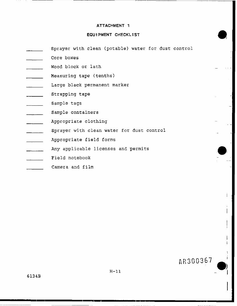
ATTACHMENT 1
EQUIPMENT CHECKLIST
Sprayer with clean (potable) water for dust control
Core boxes
Wood block or lath _
Measuring tape (tenths)
Large black permanent marker
Strapping tape
Sample tags
Sample containers
Appropriate clothing —
Sprayer with clean water for dust control __
Appropriate field forms -I
Any applicable licenses and permits
Field notebook
Camera and film
AR300367H-ll
6134B

Well Completion Information(Single Cased, Screened)
Project _____________________ Installation Date ________Well ___________________ Drilling Method ______Location ______________________ Drilling Company ________Top of Casing Elev. ________________ Protective Casing Matenal/Dia.Ground Elev. __________________ Inner Casing Matenal/Dia. __Screened Interval _______________ Screen Material ________Protective Casing Length (Ft.) ___________ Screen Slot Size (In)/TypeInner Casing Length (Ft.) _____________ Seal MaterialGrout Mix Ratio __________________ Filter Pack MaterialComments ________________________________________
Locking Cap
Protective CasingStick Up (Ft) .. R,ser
Stick Up (Ft)Ground Surface
Protective CasingDiameter (In)
RiserDiameter (In)
Borehole Diameter (In)
Deptr, icTop ol Seal iFti
Depth toBottom o' Sea! (Ft
Depth lo Topot Screen (Ft)
ScreenDiameter (In)
Depth toBottom ofScreen (Ft)
An3Q03GATTACHMENT 2 WELL COMPLETION INFORMATION FORM
(SINGLE-CASED WELLS)
H-12

ATTACHMENT 3
BOREHOLE/WELL COMPLETION FORM
BOREHOLE
SLIf
ITE CODEOCGER CO«ISTALLER
OFCODF
/ WELL CONSTRUCTION FIELD DATA LOG
LOCA1DRILLCOMP
TON ID ———————co fT ftF
FIELD REPBIR TYPF _
LCTON DATE ———— ACCEPTANC
BOREHOLE SUMMARY
KlTtnHOLEDUU0")
CASINGCASING"TYPE
END*DEPTH(n)
rmeTrw
SUMMARY
DESCRIPTION
.* f-rrrtx** t - Sow
Ouu0")
END *DEPTH(n)
o-e»* • -AMA D*pth from Top of Coilng
WELL CONSTRUCTION• TYPE*CODE DESCR1PTON
» B - Bockflfi S -• Depth From Ground
S*ol
END •DEPTHM
f - rat* PO<*Surfoe*
T f*nnr
CONSTRUCTION TIME LOG
AcnvmrDR1ULJNG
CASING
FOER PACK
SEAL
a*c*nu.
DCVB-OPUENT
OTHER
STARTDATE nut
ENDTtUC
WELL DEVELOPMENT
COMMENTS
. /inorA R 3 u u o o8
H-13

1.3.13 Standard Operating Procedure — Borehole GeophysicalLogging of We I Is
Purpose: The purpose of borehole geophysical logging is toprovide an objective, instrument-based description and correla-tion of the geologic composition of the rock into which thewell was drilled.
Descript ion: Borehole geophysical logging will use five dis-tinct instruments to describe the stratigraphy and delineateflow zones in the surrounding borehole. Four of these instru-ments must be run in an uncased well or prior to casing of thewell. These are:
• The fluid temperature log, which records the tempera-ture of the groundwater in the borehole. This tool isrun as part of the first suite of logs before repeatedtool lowering and raising mixes the water. Differen-ces in temperature on this log help identify fracturesor joints which yield water.
• The caliper log, which measures the physical size ofthe annulus (hole). Fractured portions of the rockmay create a larger annulus than the bit size due towashout.
• The resistivity log, which measures the electrical re-sistance to current flow in the rock and the fluidcontained in the rock.
• The spontaneous potential log, which measures the selfpotential or electromotive force between the fluid inthe borehole and the fluid in the rock.
• The gamma-gamma log, which records how the formationscatters gamma radiation emitted from a source on thetool. The relative densities of the surroundingformations can be compared using this tool. Thegamma-gamma log has the advantage that it can be runin cased holes and in holes without fluid.
Borehole logging at CSG will commence at the first deep moni-toring well that has been drilled to total depth (TD). Loggingcan be performed immediately after widening the annulus beforeinstalling casing. The five logging instruments will be run,logs recorded, and the probes withdrawn from the holes. Log-ging probes and connecting cables will be decontaminatedaccording to Appendix N before storage or insertion intoanother well.
During packer testing or while casing is being installed in theinitial deep, cored monitoring well, borehole geophvsu£3*> wW-A -be
Hnouuo /O1.3-46
6135B

run in MOS- 11 and -18. Should the second deep well be readyfor geophysical logging before the MOS wells are all logged,then the second deep well will take precedence and the MOSwells will be logged later. Borehole logging of the AudubonWater Company wells AUD MW-1 and AUD MW-2 will commence onlywith permission from the owner, Audubon Water Company. AUDMW-1 and MW-2 will be logged between drilling or casing opera-tions as with the MOS wells.
Procedures: See Appendix I.
AR30037I1.3-47
6135B

APPENDIX I
BOREHOLE GEOPHYSICAL LOGGING OF WELLS
"35B AR300372

c. Ensure all downhole instruments have been thoroughlydecontaminated.
I.4.2 Office
Deliver original log and three copies to the Site Geologistfor eventual delivery to CSG and EPA.
W3003731-3
6135B

APPENDIX I
BOREHOLE GEOPHYSICAL LOGGING OF WELLS
1.0 PROCEDURES
1.1 ASSOCIATED PROCEDURES
Appendix
M
N
1. 2 PREPARATION
1.2.1 Office
Appendix Title
General Instructions for Field Personnel
General Equipment Decontamination
a. Review associated procedures.
b. Coordinate schedules/actions with CSG staff, SiteGeologist and drilling subcontractor.
c. Coordinate site access; permission is required forentry into wells not owned by CSG.
d. Obtain an up-to-date site map with well locations andproposed well locations.
e. Ensure all logging equipment is in working order; thatthe generator functions properly and that all batter-ies are charged.
I.2.2 Field
a. Ensure all logging equipment, generator, and associa-ted equipment is in proper working order.
b. Decontaminate all downhole equipment before entry intoany well (see Appendix N).
c. Discussion with driller on total depth of well, welldiameter, and borehole conditions.
AR30037I*1-16135B

I .3 OPERATI ON
a. If a generator is used, it will be placed outside ofthe logging vehicle and down-wind of the monitoringwell.
b. If the well has been found closed (and locked) thewell will be opened to vent possible organic vapors. j
c. All downhole logging probes will' remain within theirclean transportation cases or be placed on clean Jsheets of plastic upwind from generators or vehicle jexhaust fumes.
d. Manufacturer's operational procedures for all logging jequipment must be followed in the step-by-step mannerpresented. Each type of instrument will have themanufacturer's instructions for start-up, warming pro- |cedure, calibration steps, signal attenuation during Ilowering of probe(s), initiation of recording, re-re-cording over areas recorded off-scale and final print- iing of logs on scaled, headed paper. J
The manufacturer's operational procedures shall be ^followed for temperature, spontaneous potential, Iresistivity, caliper and gamma gamma logging. f
e. At the completion of each logging run, the type of in-strument and appropriate scale will be marked on thelog in addition to the depth. The log heading will becompleted filling in the site name (Commodore Semicon- •ductor Group), date, time, location (well number) cal- |ibration data, name of operator, and any other perti-nent information, i.e., logging speed, to the in-terpretation of that geophysical log. I
f. At the conclusion of logging activities, the loggingprobe(s) and cable will be decontaminated in ac- 1cordance with procedures in Appendix N.
I.4 POST OPERATION
1.4.1 Fie l d Ja. Do not disconnect probe or initiate another logging I
run until a satisfactory log has been recorded. In- Ispection by the Site Geologist would be advisable be-fore running another logging instrument. 1
b. Ensure that all probes are returned to their propercontainers for safe transport. »
AR30Q3751-2
6135B

1.3.14 Standard Operating Procedure — Monitor Vapor Probes
Purpose: To define the aerial extent of volatile organiccontamination at the soil-rock interface and in the lower soilunit at the CSG site.
Discuss ion: Soil borings/vapor probes will have been in-stalled at approximately 15 locations at the CSG site (seeFigure 1-29). The screened portion of the boring/probes willbe at the unconsolidated soil/bedrock interface. Dense, non-aqueous phase liquids travelling along this interface should bedetectable with an FID, an Organic Vapor Analyzer (OVA) insert-ed at the probe top. Probe readings will be obtained once amonth and over dry and wet seasons to monitor variance overtime and between seasons. Readings will be recorded in thefield notebooks and entered into a computer data managementprogram at a later time.
Procedures: See Appendix J.
AR3003761.3-48
6135B

APPENDIX J
MONITORING SOIL VAPOR PROBES
J.1 ASSOCIATED PROCEDURES
Appendix No . Appendix Title
— OVA operationB Water level measurementM General Instructions for Field PersonnelN General Equipment Decontamination
J
J
J
J
. 2 PREPARAT I ON
.2.1 Office
a. Review the RISOP and associated Appendices.iar with all the locations to be monitored.
b. Ensure that the OVA is properly calibratedcalibration gas designed for the CSG site is
c. Secure decontamination liquids and equipment.
.2.2 Field
Be famil-
and thatavailable.
a. Ensure all equipment (i.e., OVA, notebook, depth-to-water meter) are present and functioning properly be-fore unlocking probe.
b. In a stepwise fashion, work through the procedures inthe next section.
o
.3 OPERATION
The procedures are as follows:
1. Check OVA for proper operation and calibration.
2. Unlock vapor probe/piezometer. If this task is beingcompleted in level "D" safety protection, all person-nel will be in an upwind position from the probe.
3. Field notebooks and pen will be part of thg macpjaaqa yjequipment to record date, time, probe number, 'weraTfter,sampler's name, and all instrument readings from theprobe.
J-l6135B

4. The OVA will be set on a higher scale before measure-ment.
5. The sampling tip of the OVA will be carefully insertedthrough a plugged sample part or between the cap andstandpipe as the cap is first being removed.
6. Readings will be recorded at initial insertion, at 10seconds and at 30 seconds. If the readings are withinbackground range for one/half minute, readings may bestopped and the probe cap fully removed to check forwater in the probe. If meter readings are above back-ground readings, the probe cap will be removed to al-low the well/probe to vent; however, the meter will bemaintained in place to determine the lower meterreading.
7. Probing for liquid in the vapor probe/piezometer willnot commence till the probe vents to an acceptablelevel in the breathing zone.
8. Upon completing the probe monitoring, liquid check,liquid level measurement, and recording all informa-tion and meter readings, the probe/piezometer will berecapped and securely locked.
J.4 POST OPERATION
Distribute original information/field notebooks to Site Geolo-gist, enter data into data management program, for eventual de-livery to CSG and EPA.
I
i
JJ
J-26135B

APPENDIX J
MONITORING SOIL VAPOR PROBES
AR3003796135B

1.3.15 Standard Operating Procedure — Hydrogeologic Testing
Purpose: To define procedures to be followed in conductingpacker tests to determine the hydraulic properties of water-bearing and associated rocks.
Discussion: A packer test measures the artificial fluctua-tion of the groundwater level in a well over time due to thewithdrawal of a volume of water beneath the groundwater sur-face. The primary advantages of using packer tests to estimateconductivities are: (a) estimates can be made in situ anderrors incurred in laboratory testing of disturbed samples areavoided; and (b) the hydraulic conductivity of small discreteportions of an aquifer can be estimated (i.e., sand layers in aclay). Limitations of packer testing include: (a) only thehydraulic conductivity of the area immediately surrounding thewell is estimated, which may not be representative of theaverage hydraulic conductivity of the area; (b) certain assump-tions are made in the analysis process; if the assumptions madeare inappropriate for the geologic conditions at the site, thepacker test data are invalid; (c) the storage coefficient, S,usually cannot be determined; and (d) data sufficient for anal-ysis may not be collected if the hydraulic conductivity isrelatively high.
Aquifer testing has been conducted at the CSG site on two occa-sions. The calculated hydraulic conductivity for the Stocktonformation was given at:
0.54 ft/day drawdown test, July 1981 (SMC Martin, July 1984)0.22 ft/day recovery test, August, 1983
The degree of fracturing at the site is currently unknown.Packer testing, or the withdrawal of liquid from discrete zoneswhich have been segregated from the rest of the well by pack-ers, will be conducted on a maximum of three deep wells basedon the results of well drilling observation, rock core analy-sis, and bore hole geophysics of the Stockton Formation it theCSG site. (See Procedure in Appendix K).
The zones to be tested will be selected on the basis of rockcore examination and borehole geophysical log interpretation.Intervals where the rock core shows solution widening of frac-tures or joints will be tested. Anomalies in the geophysicallogs, such as SP-resistivity changes in an area of uniformstratigraphy, or temperature decreases or shifts as the toolmoves up-hole, would indicate intervals to be packer tested.
It is presently anticipated that several zones (or intervals)in approximately three wells will be packer tested. Based oncore examination and borehole geophysical data, discrete zones
AR3003801.3-49
6135B

of the well that are intepreted as probable fractured zoneswill be segregated from the rest of the borehole by packers. Apressure transducer will be placed in the test well above theupper packer, a second transducer will be placed within thestraddled interval, and a third transducer will be placed belowthe lower packer (Figure 1-36). Additional transducers will beplaced in nearby wells. Baseline readings will be recordedbefore actual testing begins. After collection of adequatebaseline data, water will be pumped from between the packers inthe test well. Data will be recorded until the formation reachesequilibrium or the formation is pumped dry. A maximum of 20water samples will be collected for VOC analysis during thepacker testing. The objective of the water quality analyseswill be to indicate if the groundwater contamination is limitedto one zone or to several zones.
iIJ
SR30038I1.3-50
6135B

Submersible Pump ——————
1 Innpr Pni^lfArInflation LineTransducer ———— <Locations
Transducer Tube ———————for Upper ZoneMeasurements
C
Galvanized Riser — —— — —Pipe (2.5" O.D.)Transducer Tube ———————for Middle ZoneMeasurements
Lower Panksr , ,„.„,Inflation Line
PerforatedRiser Pipe
(
Lower Packer ——————— *
(Transducer Tube —————— *-for Lower ZoneMeasurements
175-860a
!f
\nnnnnunnii
— >
I
A111111
1wh->•
*•• i>•>•••••:!
_J
^
"" - ————iiuunnJL.... 1 ~* —————
"') •* —————
^ ————— 1
— Seal Length: 2 ft.
— Straddled IntervalApproximately 10 ft.
Spacings
— Seal Length: 2 ft.
AR300382FIGURE 1-36 SCHEMATIC OF BOREHOLE STRADDLE PACKER
1.3-51

APPENDIX K
HYDROGEOLOGIC TESTING
6135B

APPENDIX K
HYDROGEOLOGIC TESTING
K.1 ASSOCIATED PROCEDURES
K.2
K.2
Appendix
B
M
N
PREPARATIONS
.1 Office
Appendix Title
Water Level Measurement
General Instructions for Field Personnel
General Equipment Decontamination
a. Review the Remedial Investigation Site OperationsPlan (RISOP) and associated Appendices.
b. Coordinate schedules/actions with CSG and EPA staff.
c. Review the operator's manual provided with the elec-tronic data logger, if appropriate.
d. Checkout and ensure the proper operation of all fieldequipment. Ensure that the electronic data logger isfully charged, if appropriate. Test the electronicdata logger using a container of water (e.g., sink,bucket of water). Always bring additional trans-ducers in case of malfunctions.
e. Assemble a sufficient number of field forms to com-plete the field assignment.
K.2.2 FieldJa. Locate monitor wells to be tested and appropriate
decontamination areas.
b. Assemble appropriate testing equipment. «
c. Decontaminate the transducer and cable as specified iin the sampling plan and Appendix N, General Equip- fment Decontamination (if equipment was flipo-Otaminated previously) . H i \ o
K-l6135B

d. Make initial water level measurements to an accuracyof 0.01 feet on monitor wells in an upgradient todowngradient sequence, if possible.
e. Before beginning the packer test, information such asdepth of the packers, the amount and any changes inwater volume, and any changes in packer pressure willbe recorded in the field logbook and entered into theelectronic data logger. The type of information mayvary depending on the model used. When usingdifferent models, consult the operator's manual forthe proper data entry sequence to be used.
f. Test wells from least contaminated to most contami-nated, if possible.
g. Prior to starting the packer testing, the Site Geolo-gist will select the discrete zone(s) to be tested.New or decontaminated packers will be placed in thewell bore at the depths indicated by the Site Geolo-gist. The drilling subcontractor will test the pack-ers for leakage, if possible.
K.3 OPERATION
The following general procedures will be used to collect andreport packer test data. The procedures required for a par-ticular test may vary slightly from those described, dependingon site-specific conditions.
a. When the packer test is performed using an electronicdata logger and pressure transducer, all data will bestored internally or on computer diskettes or tape.The information will be transferred directly to themain computer and analyzed. A computer printout ofthe data shall be maintained in the files as docu-mentation.
b. If the packer test data is collected and recordedmanually, the field log book will be used to recordobservations. The packer test data shall be recordedas follows:
1. Site name.
2. Location proximity and well number.
3. Log date. The date when the water samples werecollected in the format, month, day, year (e.g.,January 31, 1987).
4. Volume of water removed (FT$ft300385
K-26135B

5. Driller company name and names of individuals.
6. Comments. Appropriate observations or informa-tion for which no other blanks are provided.
7. Elapsed time (min). Cumulative time readingsfrom beginning of test to end of test in min-utes.
8. Depth to water (ft). Depth of water recorded intenths-of-feet.
9. Depths of each packer (including packer tops andbottoms).
10. Pressure changes in packers.
c. Procedures for conducting a packer test.
1. Prior to each testing zone, obtain static waterlevels from each zone and calibrate the pressuretransducers to these static levels (T.O.C.) (seeAppendix B, Water Level Measurements). Thedatum shall be the top of the well casing.
2. Cover sharp edges of the well casing with ducttape to protect the transducer cables.
3. Install the transducer and cable in the well toa depth below the target drawdown estimated forthe test. Be sure this depth of submergence iswithin the design range stamped on the trans-ducer. Temporarily tape the transducer cable tothe well to keep the transducer at a constantdepth.
4. Connect the transducer cables to the electronicdata logger.
5. Enter the initial water level and transducerdesign range into the recording device accord-ing to the manufacturer's instructions. (Thetransducer design range will be stamped on theside of the transducer.) Record the initialwater level on the recording device.
6. Inflate the packer(s) and allow each isolatedportion of the borehole to stabilize. Doublecheck each pressure transducer manually andrecord the head differentials above, between andbelow the packer(s).
AR300386K-3
6135B

7. Begin pumping of the test zone selecting a flowrate which will adequately stress the testzone. It is preferable to select a high pumprate and adjust back only if the zone appears tobe dewatering. Otherwise, maintain a constantpump rate and record the drawdown in the testzone and in the isolated borehole portions aboveand below the straddled zone. The objective isto obtain a stable drawdown which can bemaintained to within +0.5 ft. over a 30 minuteperiod with constant rate pumping. Specificcapacities can be accurately estimated bydividing the pumping rate by the feet ofdrawdown (gpm/ft).
8. Assign time zero (to) to the beginning of thepumping interval. Measure and record the depthto water and the time at each reading. Depthsshould be measured to the nearest 0.01 ft. Thenumber of depth-time measurements necessary tocomplete the test are variable. It is criticalto make as many measurements as possible in theearly part of the test. The number and inter-vals between measurements will be determinedfrom earlier previous aquifer tests or evalua-tions .
9. Analytical samples should be collected once astable drawdown has been obtained (as above),general water quality parameters have stabilizedand a minimum of three (3) test interval volumeshave been purged. Analysis will be quick-turn-around quantitative analysis to determine rela-tive VOC concentrations within the straddledinterval.
10. Continue measuring and recording depth-timemeasurements until the water level returns toequilibrium conditions or a sufficient number ofreadings have been made to clearly show a trendon a semilog plot of time versus depth.
11. Shut down the pumping phase of the test and shutin the flow control valve to prevent water inthe purge line from reversing back downhole.Monitor the recovery of the test zone until aminimum of 90 percent recovery is obtained.
12. End test and deflate packer(s) moving up theborehole to the next zone of interest.
&R30Q387K-4
6135B

NOTES:
• The time required for a packer test to be completedis a function of the volume of water removed, thehydraulic conductivity of the formation and the typeof well completion. The volume of water should belarge enough that a sufficient number of water levelmeasurements can be made before the water level re-turns to equilibrium conditions. The length of thetest may range up to several hours.
• If the well is to be used as a monitor well, precau-tions should be taken that the wells are not contami-nated by material introduced into the well. Bailersor measuring devices should be cleaned before thetest. If tests are performed on more than one moni-tor well, care must be taken to avoid cross contami-nation of the wells.
• Packer tests shall be conducted on relatively undis-turbed wells. If a test is conducted on a well thathas recently been pumped for water sampling purposes,the measured water level must be within 0.01 ft ofthe water level before sampling.
• Purged water will be discharged to city sewerfacilities if the necessary permits can be obtained.If local authorities will not issue permits, packertesting will not be performed.
K.4 Post Operation
K.4.1 Field
a. Decontaminate and dispose of equipment and rope ac- ~"cording to Appendix N, General Equipment Decontami-nation.
b. If using an electronic data logger:
l. Stop logging sequence \2. Print data, or send data to computer by
telephone. *
3. Save memory and disconnect battery at the end ofthe day's activities.
c. Replace testing equipment in storage containers. J
K.4.2 Office
a. Inventory sampling equipment and suppliesreplace all broken or damaged equipment.
K-56135B
"j
1

b. Replace expendable items.
c. Return equipment to Equipment Manager and report in-cidents of malfunctions or damage.
d. Review field forms for completeness.
e. Deliver original forms and logbooks to the Site Mana-ger (copies to the Technical Manager) for eventualdelivery to the CSG and EPA.
f. Interpret packer test field results with ProjectHydrogeologist or Site Manager. Analyze packer testusing appropriate software packages or graphicalsolutions.
g. Send data logger or pressure transducers to factoryfor recalibration, if needed.
K.5 References
Bower, H., 1978. Groundwater Hydrology. New York: McGraw-Hill Book Company
Cooper, Jr. H.H., J.D. Bredehoeft, and S.S. Papadopulos, 1967."Response of a Finite-Diameter Well to an Instantaneous Chargeof Water." Water Resources Research 13, no. 1.
DOI. n.d., Ground Water Manual, U.S. Department of the Interiorpublication.
Earlougher, R.C. 1977. Advances in Well Test Analysis, Societyof Petroleum Engineers of AIME publication.
Freeze, R. Alien and John A. Cherry, 1979. Groundwater.Englewood Cliffs, New Jersey: Prentice-Hall, Inc.
Hvorslev. 1951. "Time Lag and Soil Permeability in Ground-Water Observations," 50. U.S. Army Corps of Engineers,Bulletin No. 36.
Johnson Division, UOP, Inc., 1966. Groundwater and Wells,Johnson Division, UOP, Inc. publication.
Lohman, S.W., 1972. "Ground-Water Hydraulics," 70. U.S.Geological Survev Paper 708.
Neuman, S.P., 1972. "Theory of Flow in Unconfined AquifersConsidering Delayed Response of the Water Table." WaterResources Research 8, no. 4: 1031.
Todd, David K., 1980. Groundwater Hydrology, 2d eJohn Wiley & Sons.
Walton, William C., 1970. Groundwater Resource Evaluation, NewYork: McGraw-Hill Book Company.
K-66135B

ATTACHMENT 1
EQUIPMENT CHECKLIST
Tape Measure'(subdivided into tenths of feet)
Water level measuring device:
_____ Water Pressure Transducer.
_____ Electric Water Level Indicator.
_____ Weighted Tapes with Plopper.
_____ Steel Tape (subdivided into tenths of feet).
_________ Electronic Data Logger (if transducer method isused).
__________ Watch or stopwatch with second hand.
_________ Semi-log graph paper (if required).
_________ Water-proof ink pen and logbook.
_________ Thermometer.
_________ Appropriate references and calculator.
J
AR300390 j"K-76135B

1.3.16 Standard Operating Procedure — Collect Water Samples
Purpose: To define guidelines to ..be__fp_llpwed._by field person-nel for sampling domestic, public supply, irrigation, and moni-toring wells.
Description: Water samples will be collected frpm domestic,public supply, irrigation, and monitoring wells to supportcharacterization of the CSG site. Site-specific samplinginstructions and locations will be documented at the end ofthis subsection.
Water samples will be analyzed for VOCs listed in Table 1-12.In addition, two groundwater samples will be analyzed for tar-get compounds and target analytes. It it planned that oneTCL/TAL sample will be collected from a monitoring well nearthe CSG facility in order to determine whether any compoundsbesides the known suite of VOCs were associated with the tankleakage. The other sample will be taken from a well fartherfrom the CSG site to determine whether any compounds that mayhave been associated with the leaking tank have migrated fromthe area of the CSG facility. The optimal well in the lattercase would be VFCC-2 or 1161 Rittenhouse Road, where ground-water contains very low concentrations of VOCs. A full scan oftarget compounds and analytes in the groundwater at these loca-tions would help determine health risks other than exposure toVOCs.
It will be useful to collect the available details concerningwell installation and development. Sample collection proce-dures must be carefully followed and well documented so thatthe procedures do not contribute to the collection of erroneousdata.
Care must also be taken in promoting strong community relationswith private, public, and industrial neighbors in the vicinityof the facility. Successful completion of well samplingaccording to the standard operating procedure will impressneighbors with the professionalism and quality management of '.the program. More important, adherence to properly documentedfield procedures will ensure that privately owned wells do not .become damaged or contaminated as a result of sampling activi- jties. Residential well locations are presented in Table 1-14.The locations of residential, public supply, irrigation, andmonitoring wells are shown in Figure 1-37. Historical datafrom these wells is listed in Subsection 1.1.18. '
Collection of surface water samples has been eliminated from jthis RI by EPA unless the results of the RI indicate surface Jwater as a probable migration pathway. Surface water sampleswill be collected if EPA requires that this task be performed ••?at a later date. AR30Q39 i j
1.3-526136B

Table 1-14
Resident ial We I Is
Number of Filter Units Number of Filter Units
Janet McGarg 1 Benjamin Moore 1835 Rittenhouse Road 2711 Audubon RoadNorristown, PA 19403 Norristown, PA 19403
Nancy Goulder (renter) 1 "Renter" 1John Neilson (owner) 2714 Audubon Road839 Rittenhouse Road Norristown, PA 19403Norristown, PA 19403
James Van Horn 1 George Gear 11151 Rittenhouse Road 2615 Audubon RoadNorristown, PA 19403 Norristown, PA 19403
Salvatore Cotteta 2 Alex Chmelewski 11161 Rittenhouse Road 2618 Audubon RoadNorristown, PA 19403 Norristown, PA 19403
Elmer Hemming 1 Anthony Branch 12669 Egypt Road 2619 Audubon RoadNorristown, PA 19403 Norristown, PA 19403
Jim Bucci (renter) 1 Protect-A-Life . 12660 Audubon Road 2622 Audubon RoadNorristown, PA 19403 Norristown, PA 19403
Michael Stein (renter) 1 Matthias Yolum 1Mitch Finkelstein (owner) 2623 Audubon Road2700 Audubon Road Norristown, PA 19403Norristown, PA 19403
Carsa Davis (renter) 1 Donald Pell (renter) 1Mitch Finkelstein (owner) 2627 Audubon Road2702 Audubon Road Norristown, PA 19403Norristown, PA 19403
Salvatore Cotetta (owner) 1 Stephen Zappacosta 12703 Audubon Road 2631 Audubon RoadNorristown, PA 19403 Norristown, PA 19403
Karl Eisenberger 1 Robert Taber 12705 Audubon Road 2635 Audubon RoadNorristown, PA 19403 Norristown, PA 19403
T r * AR300392John Brenz 1 James Gordon . A2709 Audubon Road 2789 Audubon RoadNorristown, PA 19403 Norristown, PA 19403
1.3-536136B

GeneralWashingtonCountry Club
LegendPublic Supply WellResidential Well
O Monitoring WellIrrigation Well
(F) Filter Installed by CSG(f) Filter Installed by Homeowner
>2705(F)
NomtonTownship
FIGURE 1-37 PREVIOUS AND CURRENT SAMPLING LOCATIONS,VALLEY FORGE CORPORATE CENTER AREA
1.3-54

Domestic Well Locations
Domestic water sampling has been an ongoing activity performedby Commodore since September 1984. CSG installed 23 whole-house filters on 22 houses from the original sampling popula-tion of 43 residences (Table 1-14). These filters were in-stalled on every well having greater than 1 part per billionTCE in the water tested, except where the homeowner declinedthe filter. Of the 22 homes with filters, 11 have had at leastone round where the MCL was exceeded for at least one of thecompounds of concern (Table 1-4). Each sampling round concen-trates on these 11 residences. Statistically, it has only beenpossible to gain entry into approximately nine or ten of theseresidences through prior contact, sampling after normal workhours and on weekends. However, the RISOP plans for 17 resi-dence samples. Samples are generally collected before thefilter. However, pre-filter and post-filter samples are col-lected about every third round to test filter effectiveness.The RISOP plans for pre-filter and post-filter analyses dur-ing the second round of groundwater sampling. Should thefilters require changing, the used carbon is disposed of with ahazardous waste hauler.
Public Supply Well Location
The public supply wells to be sampled are owned and operated byAudubon Water Company (2650 Eisenhower Avenue) at the ValleyForge Corporate Center. The locations of these wells can beseen in Figure 1-37 marked as: VFCC-2, VFCC-3, VFCC-4, AUD-3,and AUD-5.
At the time of the writing of this document, Audubon Water Com-pany will not allow CSG to test water from these public supplywe11s.
Irrigation W e l l Location
The irrigation wells to be sampled (GW-1, GW-2, and GW-3) areon and owned by the General Washington Country Club. They arealso marked in Figure 1-37. Well GW-3 is in the main clubhousecomplex and is operational and able to be sampled all year.Wells GW-l and GW-2 are only operational from April to Novembersolely as irrigation wells. These two wells are shut down forthe winter starting in November of every year.
Monitor We I I Locations
The monitor wells to be sampled include seven existing wells,MOS-3, MOS-11, MOS-13, MOS-15, MOS-18, AUD MW-1, and AUD MW-2,and nine new monitor wells.
Procedures: See Appendix L. fiR30039^
1.3-556136B

APPENDIX L
COLLECT WATER SAMPLES
6136B

APPENDIX L
COLLECT WATER SAMPLES
L.1 ASSOCIATED PROCEDURES
Appendix
BMOPN
Appendix Title
Water Level MeasurementGeneral Instructions for Field Personnel ^Sample Control and DocumentationGuide to Handling and Packaging of SamplesGeneral Equipment Decontamination
L.2 PREPARATION I
L.2.1 Of
a .
b.
c.
d.
e.
f ice
Review the RISOP and associated appendices. !
Coordinate schedules/actions with CSG Project Coordi- ^_ jnator . ^B
Coordinate schedules/actions and site access with ,members of the public and industry management and jobtain necessary keys. Domestic well owners will also _ Lbe contacted before samples are collected. ~~
Assemble a sufficient number of field documentation to |complete the field assignment. Instructions fordocumentation in the field notebook are provided in *their respective standard operating procedures. j
Check out and ensure the proper operation of all fieldequipment described. A typical equipment and supplies Ilist follows: — --»
Expendables 1
2 drum liners1 1/8 in. nylon rope 11 bailer (decontaminated) J3 50-ft garden hoses1 plastic tub2 squirt bottles onnooc I2 pairs of nitrile gloves AR30Uo:JD -J
L-l6136B

1 box surgical gloves1 5-gal bucket1 roll duct tape
Rental
1 tool kit1 generator1 conductivity meter1 pH meter and standards1 submersible pump1 OVA1 water level indicator
Supplies of deionized water will be checked to ensurethat there is sufficient water for the entire samplinground. Use of 40-ml vials with Teflon-lined septa,two per sample, to be consistent with recommendationsset forth in EPA-600/4-79-020 and the RISOP.
f. Note depths of wells, if available.
g. Alert the analytical laboratory to the following:
1. Approximately how many samples it will be re-ceiving; the laboratory also might be told tosend "x" bottles for subsequent sample collectionand labels, custody seals, chain-of-custodyforms, coolers, and vermiculite.
2. Approximately when it will receive the filledsample bottles.
3. The suite of chemical constituents the labora-tory will analyze for.
4. The need for trip blanks to be prepared.
h. Determine the wells from which duplicate and matrixspike/matrix spike duplicate samples will be col-lected. Contact EPA and DER for wells requiring splitsamples.
L.2.2 Field
a. Identify local suppliers of sampling expendables(e.g., ice, plastic bags).
b. Contact well owners and set up a pre-arranged time tocollect water samples and perform field chemistrymeasurements.
/1R300397L-2
6136B

L.3 OPERATION
L.3.1 Domest ic We I Is
For collection of groundwater from domestic water supply wells,proceed as follows:
a. Calibrate pH meter.
b. Discuss activity with the well owner, if possible, andi set up the sampling vehicle in a position that will
not cause any inconvenience to anyone.
c. Determine whether the discharge pipe or water faucetis on a water treatment system of some type (i.e.,water softener). Note this in the field notebook.
d. For residential wells, locate the holding tank, whichis usually in the basement of the house. Connect thehose to the tap closest to the tank. Turn off waterto the house to prevent backwash into hose. If afilter system is present, determine inflow and out-flow pipes and connect hose to the appropriate tap.
e. From the home owner, obtain information on the depthof the well, depth of the pump, and any other infor-mation regarding the well and the filter system, ifpresent.
f. Run the unconnected end of the hose outside or to anearby sink or sump pump. Purge the well for approxi-mately 20 minutes.
g. Take readings for temperature, pH, and conducrivityafter the water has purged for approximately 5 minutesand again at 15 minutes.
h. Turn off water, disconnect hose at end of purge cycle.
i. For wells equipped with a tap, open the tap slightlyand fill the vials from the outlet, taking care not tolet the vial touch the outlet. Allow the water to rundown the side into the vial. Avoid splashing.
j. Fill the vials. Do not rinse the vials, or allow themto overflow. There should be a convex meniscus on thetop of the vials.
k. Check that the caps have not been contaminated (splash-ed) and carefully cap the vials. Place the caos_ di-rectly over the top and screw down firmly.overtighten and break the cap.
L-36136B

1. Invert the vials and tap gently. Observe vials for atleast 10 seconds. If an air bubble appears, discardthe sample and begin again. It is imperative that noentrapped air is in the sample vial.
m. One residential well will have groundwater samplescollected for TCL/TAL analysis. Each sample will re-quire filling two 40 ml VOC vials as detailed below.In addition, each water sample will require fillingtwo 950 ml amber glass bottles for base/neutral andextractable acids (BNAs or semivolatiles) analysis andone 950 ml amber glass bottle for pesticide/PCB analy-sis. The VOC, BNA, pesticide/PCB samples will be pre-served by cooling to 4°C. In addition a water samplewill be collected in a one-quart plastic container,filtered, then preserved with nitric acid for metalsanalysis. A one-quart plastic container preservedwith sodium hydroxide will be used for cyanide analy-sis. QA samples (matrix spike and matrix spike dupli-cate) require two extra samples for BNAs, pesticides/PCBs, metals, and cyanide.
n. Fill in the required information . on the custodylabels. Place custody seals on vials and wrap thevials in a self-sealing plastic bag. Place the sam-ples in a cooler that contains vermiculite and ice.
o. Ship or deliver samples to the laboratory daily. En-sure that the samples remain at 4°C, but do not allowthem to freeze.
p. If specified, collect duplicate sample and/or matrixspike/matrix spike duplicate sample.
q. One field blank will be collected after decontamina-tion at the end of each day of sampling.
L.3.2 Public Supply and Irrigation Wells
For collection of groundwater from public and irrigation watersupply wells proceed as follows:
a. Calibrate pH and conductivity meters.
b. Discuss activity with the well owner, if possible, andset up the sampling vehicle in a position that willnot cause any inconvenience to anyone.
c. For public supply wells, or irrigation wells equippedwith a pump and a tap: (1) estimate the depth togroundwater from any nearby wells, and (2) calculatethe amount of standing water in the well. AR3Q0393
L-46136B

d. Open the tap and begin purging. Note time. Notelength of time it takes to fill a 5-gallon bucket.Calculate length of time needed to purge three wellvolumes of the amount of water in the well.
\e. Take readings for temperature, pH, and conductivity
near the beginning and end of the purge cycle. j
f. Attach hose or hoses to outlet so that purge water isdirected toward the VFCC sewer system or the city tsewer inlets. j
g. At the end of the purge cycle make sure all thenecessary data have been recorded in the field note- Ibook, then follow sample collection procedures i ithrough p from Subsection L.3.1.
L.3.3 Monitoring We I Is j
For collection of groundwater from monitoring wells proceed asfollows: - j
a. Calibrate pH and conductivity meters.
b. Discuss activity with the well owner, if possible, and 1set up the sampling vehicle in a position that willnot cause any inconvenience to anyone. _i
c. Partially remove the well cap and take an OVA reading ^^from the headspace and background. Vent the well.
d. Take a water level measurement, if possible, according •to Appendix B, Water Level Measurement. If the depthof the well is known, calculate the amount of water in jthe well by subtracting the water level from the depth fand multiplying by the appropriate conversion factor(0.1632 for 2-in., 0.6528 for 4-in., and 1.4688 for •6-in. wells). I
e. Prepare a submersible pump by attaching an appropriatelength of hose to serve as an outlet. Wrap the pump Icoil and hose with duct tape in several places. »
f. Lower the pump down the well and try to position it 1approximately 1 to 5 feet from the bottom. Secure |pump by placing a large screwdriver between the pumpcoil and pump support cable and lay the screwdriver *horizontally on the well head. During the purging Icycle, the pump should be raised up the well until it *breaks suction, to sweep the well of overlying stag-nant water. 1
L-56136B
AR300UOO
T
I

g. Begin purging and note time. Place outlet hose in5-gallon bucket and note length of time it takes tofill. From this gallon/minute reading, calculatelength of time needed to purge three well volumes ofthe amount of water in the well (calculated in stepd) . Purge between three and five volumes from thewell.
h. When water from the outlet discharges silt-free orreasonably clear, take readings for temperature, pH,and conductivity. Repeat these readings near the endof the purge interval.
i. At the end of the purge interval or when the well runsdry, remove pump and allow the well to recover suffi-ciently to obtain a sample.
j. Disconnect hose at the end of purge cycle.
k. Two 40-ml vials with Teflon-lined septa are requiredfor one VOC sample.
1. One monitoring well will have groundwater samplescollected for TCL/TAL analysis. Each sample will re-quire filling two 40 ml VOC vials as detailed below.In addition, each water sample will require fillingtwo 950 ml amber glass bottles for base/neutral andextractable acids (BNAs or semivolatiles) analysis andone 950 ml amber glass bottle for pesticide/PCB analy-sis. The VOC, BNA, pesticide/PCB samples will be pre-served by cooling to 4°C. In addition a water samplewill be collected in a one-quart plastic container,filtered, then preserved with nitric acid for metalsanalysis. A one-quart plastic container preservedwith sodium hydroxide will be used for cyanide analy-sis. QA samples (matrix spike and matrix spike dupli-cate) require two extra samples for BNAs, pesticides/PCBs, metals, and cyanide.
m. For monitoring wells not equipped with a pump, pre-pare a water sampler by tying nylon rope, preferably1/8-in. , to one end. Lower the water sampler into thewell. Note when the water sampler enters the water.Sampler should be lowered to well bottom and wellsurged to mix water column. Withdraw the bailer.
n. Fill the vials from the bottom of the bailer, allow-ing the water to run down the side into the vial.Avoid splashing.
o. For wells equipped with a tap, open the tap slightlyand fill the vials from the outlet, taking care not tolet the vial touch the outlet. Allowftt$<§ §4):iE?iG t°down the side into the vial. Avoid splashing.
L-66136B

p. Fill the VOC vials. Do not rinse the vials, or allowthem to overflow. There should be a convex meniscuson the top of the filled vials.
q. Check that the caps have not been contaminated (splash-ed) and carefully cap the vials. Place the caps di-rectly over the top and screw down firmly. Do notovertighten and break the cap.
r. Invert the VOC vials and tap gently. Observe vialsfor at least 10 seconds. If an air bubble appears,discard the sample and begin again. It is imperativethat no entrapped air is in the sample vial.
s. Fill in data on sample labels.
t. Place custody seals on vials and wrap the vials in aself-sealing plastic bag. Place the samples in acooler that contains vermiculite and ice.
u. Ship or deliver samples to the laboratory daily. En-sure that the samples remain at 4°C, but do not allowthem to freeze.
v. If specified, collect duplicate sample and/or matrixspike/matrix spike duplicate sample.
w. One field blank will be collected after decontamina-tion at the end of each day of sampling.
L.4 POST OPERATION j
L.4.1 Field _ —
a. Before leaving the sampling location, cross-check }samples with those required in the RISOP. Fill outthe chain-of-custody form. i
b. Decontaminate all equipment according to Appendix N,General Equipment Decontamination.
c. Replace sampling equipment in storage containers. I
d. Prepare and transport water samples according to Ap- ipendix 0, Sample Control and Documentation, Appendix JP, Guide to Handling and Packaging of Samples.
e. Restore the area where the samples were taken to its joriginal condition (i.e., clean and dry). Thank the *well owner for his/her cooperation and time.
f. At the end of the day, deliver samples to laboratory fand keep the chain-of-custody receipt. ARSOO^OZ
6136B

L.4.2 Office
a. Inventory sampling equipment and supplies. Repair orreplace all broken or damaged equipment.
b. Replace expendable items.
c. Return equipment to Equipment Manager and report in-cidents of malfunctions or damage.
d. Review field forms for completeness.
e. Deliver original forms and logbooks to the Site Man-ager for eventual delivery to CSG and EPA.
f. Contact laboratory to ensure that samples arrivedsafely and that instructions for sample analysis areclearly understood.
L.5 REFERENCES
U.S. Environmental Protection Agency, Methods for ChemicalAnalysis of Water and Wastes, EPA-600/4-79-020. Washington,DC, U.S. Government Printing Office, 1983.
AR3001403L-8
6136B

1.3.17 Standard Operating Procedure — Analyze Water Samples
Purpose: To detect Volatile Organic Compounds (VOCs) in watersamples collected from the CSG site. To detect target com-pounds and target analytes in two water samples collected fromthe CSG site.
Discussion: Groundwater samples will be collected fromexisting monitoring wells, irrigation wells, residential wells,and public supply wells, if permission is obtained. Ground-water samples will also be collected from newly installed moni-toring wells. A critical part of this remedial investigationwill be to determine the VOC content of each of these samples.
Methods 601 and 602 have been selected as the methods ofchoice. The following volatile organic compounds are analyzedfor at the CSG site:
ChloromethaneBromomethaneVinyl ChlorideChloroethaneMethylene ChlorideTrichlorofluoromethanel,1-Dichloroethene1,l-DichloroetheneTrans-1,2-dichloroetheneChloroform1,2-Dichloroethane1,1,1-TrichloroethaneCarbon TetrachlorideBromodichloromethane1,2-DichloropropaneTrans-1,3-DichloropropeneTrichloroethaneDibromcchloromethane1,1,2-TrichloroethaneBenzenecis-l,3-Dichloropropene2-ChloroethylvinyletherBromoformTetrachloroethene1,1,2,2-TetrachloroethaneTolueneChlorobenzeneEthylbenzeneTotal Xylenes1,2-Dichlorobenzene1,3-Dichlorobenzene1,4-Dichlorobenzene
1.3-566136B

Method 601 was also chosen so that the compounds of concerncould be detected at the following low limits:
trichloroethane (TCE) 1 ug/Ltrans 1,2-dichloroethene (1,2-DCE) 1 ug/Ltrichloroethane (TCA) 1 ug/L1,1-dichloroethene (1,1-DCE) 1 ug/Ltetrachloroethene (PCE) 1 ug/L
Standard CLP methods will be used for analyses of the twoTCL/TAL samples.
Procedure: The procedure for water sample VOC analysis willbe to follow EPA methods 601 and 602 from the Federal Register40 CFR 136, Vol. 49, No. 209, October 26, 1984, Appendix A topart 136 - Methods for Organic Chemical Analysis of Municipaland Industrial Wastewater.
1R30C4051.3-57
6136B

1.3.18 Standard Operating Procedure — Survey Wells
Purpose: The purpose of surveying the wells at CSG is toaccurately locate them, both horizontally and vertically, foran accurate map base and as a reference plane for groundwaterstudies.
Discuss ion: Groundwater monitoring wells, public supplywells and irrigation wells presently exist on or near the CSGsite. These wells have been previously surveyed; however, someof the elevations and locations appear to be incorrect. Inaddition, approximately 15 soil borings/vapor probes and ap-proximately 9 monitoring wells will be installed. All wellshave to be surveyed to correlate new data with historical data,
A licensed Pennsylvania surveyor will be procured to survey theexisting wells at the CSG site and the newly installed wellsupon their completion. Surveying will be performed to an ac-curacy of 0.01 of a foot for closure. Survey marks will beplaced on the well casing and the grout apron (or other appro-priate location). These survey marks will be recorded in thefield logbook. Reference for the closure will be the USGSBench Mark 197 within Valley Forge Corporate Center. (See USGSValley Forge, Pennsylvania 7.5 min map). All data and documen-tation will be submitted to the Site Geologist for eventual.entry into the data management plan and eventual delivery toCSG and EPA.
1.3-586136B

1.3.19 Standard Operating Procedure — Air Emissions Modelingand Test ing
Purpose: To calculate the impact of the downstream exhaustair from the existing air strippers at the CSG site on theenvironment.
Pi scussion: The forcing of large volumes of air throughwater containing volatile organic compounds causes most of thecompounds in the water to volatilize and thereby "strips" thewater of these compounds. This process is usually referred toas air stripping. Two air stripper units are in operation atthe CSG site. One is owned and operated by Audubon Water Com-pany for cleaning the water from well VFCC#4. This treatedwater is then blended with other well water for use in the Val-ley Forge Corporate Park system. The air stripper was pur-chased for Audubon by Commodore as part of Commodore's effortto clean up VOCs in the groundwater.
The second air stripper was also purchased by Commodore totreat water recovered from beneath the CSG building extension.Water entering the French drain system is pumped to this secondstripping unit where any VOCs in the water are removed. Thisunit has not been observed in operation, although it is be-lieved to be in working order and receives regular maintenance.Water levels in the overburden rarely rise to the level neces-sary to activate the French drain air stripper system. Com-modore has filed for permits to continue the existing treatment.
The downstream effects of the air plume emanating from eitherair stripper can be calculated using existing models. WESTONwill use EPA's UNAMAP-6 version of the ISC-LT model or theequivalent. Data required for this modeling is in the proce-dures section.
Procedure: To properly and accurately model the downstreameffects, the following information has been requested fromAudubon Water Company and CSG:
1. Current analyses of influent and effluent water to andfrom the stripper including all VOCs analyzed for inEPA method 601.
2. The water flow rate through the stripper.
3. The factory and tested efficiency of the stripper foreach VOC.
4. The volume air flow rate through the stripping towerin cubic feet per minute.
5. The height of the air effluent stack. fi P ? 0 fl L 07
1.3-596136B

6. The exit dimensions of the exhaust gas stack.
7. A sketch or drawing showing the dimensions of the en-tire unit to scale.
8. A plot plan showing all buildings within 500 feet ofthe stripper including dimensions of any obstructionto the downstream air plume.
9. UTM coordinates of the stripper unit.
10. Base elevation of the unit.
11. Temperature of the exhaust gas from stripper stack.
12. Hours of operation per year of the air stripper.
13. Design capacity of the stripper unit in cfm.
The data from both strippers will then be entered into theabove referenced model to calculate the downstream air effects.
1.3-606136B

1.3.20 Standard Operating Procedure — General Instructionsfor F i e l d Personnel
Purpose: To provide the field personnel with activities tobe performed before, during, and after field investigations.
Discussion: These instructions are to ensure that field per-sonnel understand the site, the objective, and schedule of thefield program, their authority, and their responsibilities.
The field personnel are responsible for the completion of thetasks described in the Remedial Investigation Site OperationsPlan (RISOP). They are required to document the work performedand alert their immediate supervisor of the variances from theRISOP.
1.3-61

APPENDIX M
GENERAL INSTRUCTIONS FOR FIELD PERSONNEL
6127B22

APPENDIX M
GENERAL INSTRUCTIONS FOR FIELD PERSONNEL
M.1 PREPARATIONS
M.1.1 Office
a. Obtain all information related to purpose and intentof field program for which the field personnel are -obe responsible. This may include, but is not limi dto:
1. Scope of work or work plan detailing the RISOP.
2. Previous reports related to site.
3. Reports related to area,
4. site maps.
5. Area maps.
6. Access agreements.
7. Subcontractor's work plan.
8. Field forms and equipment checklists.
9. Associated appendices.
10. Health & safety plan.
b. Arrange for field vehicles, equipment and traveladvances, and provide copies of itinerary to personnelsponsoring the field work.
c. Coordinate schedules and activities with the FieldTeam Leader and the facility where the work is to beperformed.
d. Verify that all applicable equipment and materialshave been accounted for and prepared for shipment .
e. Contact the laboratory before sampling activitiesbegin.
f. Contact the carrier for the handling, packaging, andshipping of samples.
M-l6127B13

M.1.2 Field
a. Check the condition and operation of all supplies andequipment on-site.
b. Check decontamination zones and public access barriers.
M.2 OPERATI ON
a. General Duties
1. The field personnel are to monitor and providetechnical direction of the field work, log sam-ples, take measurements, and, in some cases,package and ship samples.
2. Under the direction of the Site Manager, fieldpersonnel may designate sampling or hole loca-tions, depth and completion zones, sample typeand depths, approve and record procedures, mate-rials, and all activities conducted in compliancewith the RISOP.
3. Additional duties which the field personnel shallperform, if applicable, are:
a) Keep a written daily log in which will berecorded all equipment, personnel, and ac-tivities on the site, as well as weather orsite conditions affecting the activities.The field personnel will note all conversa- Jtions regarding instructions or information ireceived or given which is pertinent to thejob. i
b) Keep a written daily log of all activities,including such information as start and stoptimes, supplies used, footage drilled/in- jstalled, site observations, etc. *
c) Contact the Site Manager daily and provide a |progress report. J
d) Observe that the subcontractor complies with <the RISOP and all applicable permits and Ii- jcenses.
e) Complete all field forms in accordance with |applicable appendices as work progresses. -J
AR300M2M-2
6127B24

f) Observe that the subcontractor complies withthe applicable health and safety require-ments. If violations are observed, thefield personnel shall stop the work and im-mediately notify the Site Manager and/orSite Health and Safety Officer.
g) Monitor personnel and equipment for contami-nation when necessary and record results onappropriate forms.
h) Notify the Site Manager of any modificationsto the contract that may be required or ap-propr i at e. Work not defined in the RISOP isnot to be initiated without approval by theSite Manager.
M.3 POST OPERATION
M.3.1 Field
a. Ensure that all equipment is accounted for andready for shipment.
b. Complete all field and data forms.
c. Record any work left undone such as site restora-tion.
d. Record cleanup procedures.
M.S.2 Office
a. Submit copies of all field and data forms to theSite Manager for verification and distribution.These forms will eventually be delivered to CSGand EPA.
b. Check all equipment and supplies, prepare requi-sitions for the repair of all unserviceableequipment, prepare requisitions for the replace-ment of expended supplies.
c. Submit final travel expense report.
d. Turn in monitoring equipment and other assignedpersonal equipment.
M-36127B25

1.3.21 Standard Operating Procedure — General EquipmentDecontaminat ion
Purpose: To. describe methods used for decontamination offield equipment that becomes potentially contaminated during asample collection task. The equipment may include splitspoons, bailers, trowels, shovels, hand augers, or any othertype of equipment used during field activities.
Discussion: Decontamination is performed as a quality assur-ance measure and a safety precaution, It prevents cross-con-tamination between samples and helps to maintain a clean work-ing environment for the safety of all field personnel.
Decontamination is mainly achieved by rinsing with liquidswhich include: soap or detergent solutions, tap water, rr.etha-nol, and deionized water. Equipment will be allowed to air dryafter being cleaned or may be wiped dry with chemical freecloths or paper towels if immediate re-use is needed. Steamcleaning shall be used whenever visible contamination exists,or for large machinery/vehicles.
It is the primary responsibility of the Site Manager to assurethat proper decontamination procedures are followed and thatall waste materials produced are properly stored or disposed of.
It is the responsibility of all personnel involved with samplecollection or decontamination to maintain a clean working en-vironment and to ensure that any waste decontamination productsare not introduced into the environment.
AR300UI*1.3-62
6127BO

APPENDIX N
GENERAL EQUIPMENT DECONTAMINATION
6127B18 AR300M5

APPENDIX N
GENERAL EQUIPMENT DECONTAMINATION
N.1 ASSOCIATED PROCEDURES
Appendix No. Appendix Title
M General Instructions for Field Personnel
N.2 PREPARATION
N.2.1 Office
a. Coordinate with the Site Manager to determine ifthere will need to be any specialized cleaningequipment.
b. Obtain materials listed in Attachment 1, Decon-tamination Equipment Checklist. This list pro-vides general guidance and should be modified tosite-specific needs.
N.2.2 Field
a. Assemble containers and equipment for decontami-nation .
b. Decontaminate all equipment prior to use.
N.2 OPERATION
The extent of known contamination will determine to what extentthe equipment must be decontaminated. Adequate supplies of allmaterials should be kept on hand. This includes all rinsingliquids and other materials. Decontamination will be performedin the same level of protective clothing as the sampling activ-ities unless the Site Health and Safety Plan specifies a dif-ferent level of protection.
The steps listed in the following section can be considered theprocedure for full field decontamination. Deviations from thisprocedure for a specific project will be included in the Reme-dial Investigation Site Operating Procedures (RISOP).
a. Decontamination Steps
1. Remove any solid particles from the equipment or mate-rial by brushing and then rinsing wjlth available tapwater. This initial step is to remavS09& Kf |<fpntami-nation. For drilling equipment, steam cleaning willbe necessary.
N-l6127B29

2. Wash equipment sampler with soap or detergent solution.
3. Rinse with tap water by submerging and/or spraying.
4. Rinse thoroughly with distilled water.
5. Air dry equipment or rinse thoroughly with nanogrademethanol to expedite drying.
6. Place equipment on a plastic sheet or aluminum foiland allow to air-dry for at least 15 minutes. Chemi-cal free cloths or paper towels may be used to removeexcess liquid from sampling equipment.
N.4 POST OPERATION
N.4.1 Field
Decontaminate as much as possible, and properlydispose of expendable items that cannot be decon-taminated.
Prepare the decontamination blank sample and shipit.
Store containers of decontamination solutionsproduced during decontamination in a secure area.
Dispose of any soiled materials in the designateddisposal area.
N.4.2 Office
a. Inform the Equipment Manager of materials usedand returned.
b. Obtain replacement materials as needed.
c. Designate decontamination areas.
N.5 REFERENCES
NIOSH, OSHA, USCG, and EPA, "Occupational Safety and HealthGuidance Manual for Hazardous Waste Site Activities," preparedby: National Institute for Occupational Safety and Health(NIOSH), Occupational Safety and Health Administration (OSHA),U.S. Coast Guard (USCG) and U.S. Environmental Protection Agen-cy (EPA); published by the U.S. Department of Health and HumanServices, Public Health Service, Centers for Disease Control,NIOSH, October 1985.
N-26127B13

ATTACHMENT 1
DECONTAMINATION EQUIPMENT CHECKLIST
Decontamination solutions preselected by the lab-oratory.
Cleaning liquids: soap and/or detergent solu-tions, tap water, methanol, and deionized water.
Chemical-free paper towels.
Cleaning brushes.
Cleaning containers: plastic buckets, plastictub.
Waste storage containers, drum, and plastic bags.
N-36127B31

1.3.22 Standard Operating Procedure — Sample Control andDocumentat i on
Purpose: To define the steps necessary for sample control andcompletion of the required documentation.
Discussion: The guidance provided in the Remedial Investiga-tion Site Operating Procedures (RISOP) describes the methodol-ogy of sample control and documentation that will be applied onall tasks. Accountable documents include logbooks, field datarecords, correspondence, sample labels or tags, chain-of-custody reports, and analytical records. Waterproof black inkmust be used in recording all data in documents bearing serialnumbers.
The Site Manager will supply numbered logbooks. In a logbook,the field personnel shall record all information pertinent to afield activity. All project logbooks are to be turned over tothe Site Manager at the completion of each work period and to acentral file at the completion of the field activity.
AR30tUj|S1.3-63
6127BO

APPENDIX 0
SAMPLE CONTROL AND DOCUMENTATION
6127B23 AR300l»20

APPENDIX 0
SAMPLE CONTROL AND DOCUMENTATION
0.1 ASSOCIATED PROCEDURES
Appendix Appendix Title
P Handling and Packaging of Samples.
0.2 PREPARATION
0.2.1 Office
Coordinate schedules/actions with CSG Project Co-ordinator .
Contact and inform the analytical laboratory ofthe sample types to be taken and the analysesrequested, as per the RISOP. The laboratory willthen send the necessary number and types ofsample bottles.
0.2.2 Field
Field preparation will require organizing sample bottles, sam-ple labels and chain-of-custody documentation in an orderly andsystematic manner that promotes consistency and traceability ofall data.
0.3 OPERATION
a. Field Logbook — All information pertinent to a fieldactivity must be entered in a bound book with consecu-tively numbered pager. Entries in the logbook, if notincluded on a field form, must include at least thefollowing, as appropriate:
1. Date and time of entry.
2. Purpose of sampling.
3. Name and address of field contact.
4. Site identification.
5. Type of process producing waste (if kaowix) _
6. Sample identifier and size of sample taken.
7. Description of sampling point including location.
0-16127B25

8. Date and time of collection of sample.
9. Collector's name.
10. References such as maps or photographs of thesampling site.
11. Field observations.
12. Associated field measurements made.
13. Method of sample collection, preservation tech-niques and any deviations or anomalies noted.
b. Because sampling situations vary widely, notes shouldbe as descriptive and inclusive as possible. Someonereading the entries should be able to reconstruct thesampling situation from the recorded information.Language must be objective, factual, and free of per-sonal feelings or any other inappropriate terminol-ogy. If anyone other than the person to whom the log-book was assigned makes an entry, he/she must date andsign the entry. Logbook pages are never to be re-moved. Changes in the logbook should be crossed overonce, initialed and dated.
c. Photographs — Photographs are the most accurate rec-ord of the field worker's observations. They can besignificant during future inspections, informal meet-ings, and hearings. A photograph must be documentedto be a valid representation of an existing situa-tion. Therefore, for each photograph taken, the fol-lowing items should be recorded in the field logbookand subsequently on the back of each processed photo-graph:
1. Date and time.
2. Signature of photographer.
3. Name and identification number of site.
4. Type of camera, lens, f-stop, shutter speed andfilm used, if possible.
5. General direction faced and description of thesubject.
6. Distance from photographer to object.
7. Location on site.
8. Sequential number of photograph and the io4fc
0-26127B25

Comments are to be limited to the photograph'slocation because any remarks about its contentscould jeopardize its value as legal evidence.
Photographs should be taken with a perspectivesimilar to that afforded by the naked eye. Tele-photo or wide-angle shots cannot be used in en-forcement proceedings.
d. Sample Labels — Soil and water sample identificationlabels shall be used when tagging or labeling samplecontainers. Each sample must be sealed immediatelyafter it is collected and labeled using waterproofblack ink. Label tags may be filled out prior to col-lection to minimize handling of the sampling contain-ers. Attachment 1 provides an example of the commonsample labels to be used on samples.
Occasionally, and when appropriate, sample containerswill be marked in the field using an etching toolrather than a sample label or tag. This avoids pos-sible label contamination problems and subsequent de-contamination difficulties. In this case, the dataintended for the sample label will be written into asampling logbook and transcribed onto the label afterthe sample containers have been decontaminated.
Labels must be firmly affixed to the sample contain-ers . The container must be dry enough for a gummedlabel to be securely attached. The soil sample iden-tification label must include at least the followinginformation:
1. Site Name — The name of the client, Commodore(CSG).
2. Location ID — A number assigned uniquely to eachborehole, surface monitoring location, etc.,where physical and chemical, etc., measurementsare taken.
3. Sample ID — Two-digit numbers assigned to ensurethat data collected retains uniqueness from otherdata collected, when ambiguity is possible. Twoprimary cases of using the Sample ID are: 1)actual collection of physical samples (e.g.,soil) and 2) data measurements taken at the sam-ple X, Y, and Z location. For example, multiplesoil samples may be taken in the same borehole,or multiple measurements of a given data type maybe taken at the same topographic surface loca-tion. For & given site, location- plocL atfi^ logdepth, and measured parameter, -tfiie J£abpfi.6sJ (ormeasurements) collected should be numberedsequentially to prevent duplicates.
0-36127B26

4. Log Date — The date when the form is filled outin the format: month, day, year, (e.g., October1, 1989.)
5. Depth Interval Sample:
a. Beginning Depth — Depth from ground surfaceat which top of sampling interval begins at,in the format feet and tenths of feet.
b. Ending Depth — Depth from ground surface atwhich bottom of sampling interval ends at,in the format feet and tenths of feet.
6. Pumps, samplers, and such should be numbered andrecorded to determine if they could be a contami-nant source.
The water sample identification label must include at leastthe following information:
1. Site Name — The name of the client, Commodore(CSG).
2. Location ID — Three digit number assigned unique-ly and sequentially to each borehole, surfacemonitoring location, etc,, where physical andchemical, etc., measurements are taken.
3. Sample ID — Two digit numbers assigned to ensurethat data collected retains uniqueness from otherdata collected, when ambiguity is possible. Twoprimary cases of using the Sample ID are: (1)actual collection of physical samples (e.g., wa-ter) and (2) data measurements taken at the sam-pie X, Y, and Z location. For example, multiplewater samples may be taken in the same borehole,or multiple measurements of a given data type maybe taken at the same topographic surface loca-tion. For a given site, location, log data, logdepth, and measured parameter, the samples (ormeasurements) collected should be numbered se-quentially to prevent duplicates.
4. Log Date. The date when the form is filled outin the format: month, day, year, (e.g., January31, 1987).
5. Log Time: Use military time to indicate the timethe sample was collected (HH:MM).
AR300U21*
0-46127B27

6. Analytical Parameters. Chemical constituents;e.g., VOCs, for which this water sample will betested. This is designated by the AnalyticalLab, but must be recorded on the sample bottle bythe field personnel taking the water sample.
7. Preservation Method. How a water sample is pre-served.
e. Sample Collection and Inventory — The number of per-sons involved in collecting and handling samples willbe kept to a minimum. Guidelines established in thisAppendix should be used. Field records will be com-pleted at the time the sample is collected and will besigned or initialed, including the date and time, bythe sample collector(s). Use chain-of-custody recordto inventory all samples collected in the field.
f. Custody seals with the date and the sampler's namewill be affixed to the sample bottles. This providesproof of the integrity of the sample bottle.
0.4 CHAIN-OF-CUSTODY
a. Objectives — The primary objective of the chain-of-custody procedures is to create an accurate writtenrecord that can be used to trace the possession andhandling of the sample from the moment of its collec-tion through analysis and introduction as evidence.
A sample is in someone's "custody" if:
l. It is in one's actual possession, or
2. It is in one's view, after being in one's physi-cal possession, or
3. It is in one's physical possession and thenlocked up so that no one can tamper with it, or
4. It is kept in a secured area, restricted to au-thorized personnel only.
b. Transfer of Custody and Shipment — When transferringthe samples, the transferee must sign and record thedate and time on the Chain-of-Custody Record includedas Attachment 2. Custody transfers made in the fieldshould account for each sample, although samples maybe transferred as a group. Every person who takescustody must fill in the appropriate section of theChain-of-Custody Record. To minimize custody records,the number of custodians in the chain-of-possessionshould be minimized. AR30G^25
0-56127BO

One person should be assigned to properly package anddispatch samples to the appropriate laboratory. Thisresponsibility includes filling out, dating, and sign-ing the appropriate portion of the Chain-of-CustodyRecord.
All packages sent to the laboratory should be accompa-nied by the chain-of-custody record and other perti-nent forms. A copy of these forms should be retainedby the originating office (either carbon or photocopy).
0.5 POST OPERATION
0.5.1 Fi e l d
a. Verify that all sample bottles have been correctlyidentified and labels have all necessary information(i.e., location, time, date, etc.).
b. Complete logbook entries, checking to verify accurateentries and that all pages have been signed or ini-tialed.
c. Follow Appendix P, Guide to the Handling, Packaging,and Shipping of Samples.
0.5.2 Office
a. Turn over all original sample data records (logbooks,photographs, etc.) to the Site Manager.
b. Interface with the Technical Manager concerning re-quirements for data entry and unused sample numbers.
c. Turn over logbook to the Site Manager.
0-66127B29

ATTACHMENT 1
SOIL SAMPLE AND WATER SAMPLE IDENTIFICATION LABELS
SOIL SAMPLE IDENTIFICATION TAG
SITE NAME LOCATION ID
SAMPLE ID____LOG DATE_________LOG TIME_
LABORATORY
DEPTH INTERVAL OF SAMPLE FROM DATUM:
BEGINNING DEPTH (FT FROM DATUM)____
ENDING DEPTH (FT FROM DATUM)________
SAMPLER (s)________________
ANALYSIS REQUESTED____________
COMMENTS
WATER SAMPLE IDENTIFICATION TAG
SITE NAME_______LOCATION ID____
SAMPLE ID_____ _________
BOTTLE ID
LOG DATE_______________LOG TIME_
SAMPLER(S) _____________________
ANALYSIS REQUESTED
PRESERVATION METHOD,
COMMENTS:
0-76127B30

ZUJXo<I-
1*-•
0>DO'DC
O
CO
•ooo0)cck.0)*(/)c(0H
TJO
0
alytics U
se Only
c
WESTON
I WESTON
Analytics
11
1 i~~
/-\«i.
. 1
o131»-cc
ajj
> V: a
U5 «
c
of)aJ
1 •••!-—— -••"-•
11 Shipped or
Hand-
|
0
o
•
1 '3 i
(Del
iver
ed
1MOTFS-
I
II50)£
c
ai
D "C
5 "83 cc1 2is
12 Ambient or
Chilled
NOTES:
1
i« sUJ |=W "5
la< c
OD.•
RFW Contact
Client Co
ntai
1 3 Received Broken/
|
•Do0)
CO OQ O
X
nj
OS.u
Client
ID/C
tA Use
Only
Lab ID
1 Leaking (Improperly
1
(DTO
£>
\ NOTES:
1
1
"(
•
U£/ID
>,
Lt
| NOTES: |
cXi!aa-
|
Holding Times |
z
or
2
i
^
(!(
C.
c 1 Present on
Outer | z
1
> 'cDl i
S. iC
Z
i
! §>5 S
j
13 P
resent on Sample
1
V
M I
4 Unbroken on Sample
NOTES:
Y N
toOOw.OTC
75
Q.V)
s:6* •
ac.If i|E |
o a u. _i
1 -
S O < 3:
Matrix:
S-Soll
SE - Sediment
SO - Solid
T"i
1 COG Record Was:
j
EH
a
1
IX
1.2'5o"3IT
eason
tr«
oF
(D
S
1'S
c
Relinquished bv
r
S
„ z1»5>2 a
l\3 f
'. "c
0
.
>>L
3
1 Discrepancies Between
1Samrvlo 1 aholc anH P-Df. 1
}[
) Z)))! -"")1
T)h_
ir
^
| NOTES: |
o
8
u>
I
iiII

AR30QU29

1.3.23 Standard Operating Procedure — Handling and Packagingof Samples
Purpose: To provide guidance on the selection of suitablecontainers for samples, volume required, holding times, andrecommended preservation techniques for water, sediments, andsoil samples.
General Discussion: As a general guide in choosing a samplecontainer, the ideal material of construction should be nonre-active with the sample and especially the particular analyticalparameter to be tested. A list of container size and construc-tion material required for analyses is listed in Table 1-15.
Glass or Teflon containers must be used for samples to be ana-lyzed for volatile organic compounds to prevent introduction ofextraneous organic compounds, such as those that might beleached from plastic containers. The rigid plastic screw capsfor the bottles must be Teflon lined to prevent artificial con-tamination.
Once a sample has been collected, steps must be taken to pre-serve the sample's chemical and physical integrity during tran-sport and storage prior to analysis. Samples to be analyzedfor volatile organic compounds should be stored at a tern-perature of approximately 4 degrees centigrade.
Review RISOP for specific details. An equipment checklist isincluded as Attachment 1.
I
1.3-646127BO
I!
I

in
tfi15•«•L.<D4Wre£CO4J03U•4-1COcouT3CroM0NCOL.0)BW
m•MCoo
COM- CUO r—Q.
ol2 00
VI• r-V)><
roC<
c0.!_>ro>V.CDV><U!_O.
CU.u4->CmI*.ccuc.><t—
m•acur:
ofV)rot—
0Oro
a<_>UJ
1(_)O
C VI.,- Q
•4-*CU 3N C>-•-
rOC O< C»5
J3
3J2Ca±jucu
1
uVItoro
'ai
toroCJ
VIroCT, >!1 011— >..- s-O 3</1 1/11
<B-C\J
tnr—
OC\JOco•coCO
'ool_)
V)toro"o-
£tnCMi —
, _0l/l
4-JUa'H00itnCM
T - r
V)uC/l 'r-o c.r- fOC C!ro i.
1_> CT 0O 1. => O -r-1 I 1_J _ 1 _ !(_> C_l i_>>— (— r—
O O Oo o o1-) O <_>
VI VIto viro «'ai'oi
to i. i.vi ai a116 -£ -S01 ro TO
1 's 'Etn o oCM tn tn•— c c
, _
cto
cur—a.ErO1
_O\n
KK
i— CM
-a -ac. c3 3O Ci. L.
rac\Jn m
CM0o
c=o
oou
VIVroCJI
OrXCM
1•oC !-3 CU0 *Ji. ro0 S
CUa.Sro
J VIUCU !-I— CUi — *->O ro0 S1coT
CM CM CM CM CM
.teJVI CUcu vi -aCLr- —. ro c(_> < c -" -oo 2 <— > cu >,
> CD Q. E u1 1 1 1 1
— 1 — 1 — 1 — 1 _ JC_) <_) <_J < Ut— t— 1— t— 1—
-au
r- i— r- re 3:o o o oO O O U reO U (_) •.- Z
L-
._•z.
¥ «VI VIVI toro ro
1 —— 1 —— * Kcn 01 u ui- L. *-> *J
to cu cu 1/1 v*V) J2 _C C t!ro E E r- r—r— ro ro O- Q.01
i — i — W ^-ii— E E S- UE O O re roO UO 1^ 3 3TT Cl CTi CT O-
X X X X X
CM CM i — i — i —
VICU•-\EreVI
CU
"•5u•-a.•5OJL
a.totl_i_4-> V)ro i—E —
OiT3 1Cro r—
-3Q; .-ji: «->
(/l ~C
X Jl._ a/!_ U
ro CE ci- ^o cu
a.•c E01 ro•a viro 1-
<L)Cu --J2 r—~ ',ro 1E •-
VIVI OO) O.1- -a-u CO re.a
L.ro 1)u J-<4J r ~X ••-OJ >*-1o aiS 1-i— a.K ««
IT)O
fiR30CH>3I

APPENDIX P
HANDLING AND PACKAGING OF SAMPLES
6127B54

APPENDIX P
HANDLING AND PACKAGING OF SAMPLES
P.1 ASSOCIATED PROCEDURES
Appendix Appendix Title
E Collect Soil SamplesL Collect Water Samples0 Sample Control and Documentation
P.2 PREPARATION
P.2.1 Office
The RISOP will establish the number of field samples, includingQA/QC samples to be collected. Sample containers vary accord-ing to the matrix and nature of the sample to be collected.Therefore it is necessary to: 1) identify by matrix the con-tainers required for all analyses (e.g., two glass 40 ml vialswith Teflon septa are required for each VOC analysis); and 2)calculate the number of each type of container required by theRISOP, including duplicates, blanks and matrix spike/matrixspike duplicates.
The volume of sample collected should be sufficient to performall the required analyses as well as provide for any qualitycontrol needs, split samples or repeat examinations (Table1-15).
P.2.2 F i e i d
The appropriate number and type of pre-cleaned containers andlabels with equipment and packaging containers should be readyfor field sampling,
P.3 OPERATION
A. Sample labels should be checked against chain-of-cus-tody for any discrepancies.
B. The lids of sample jars should be attached. Prepare achain-of-custody form listing the name of a responsi-ble party, sample numbers, analyses requested, and thedate of shipping.
C. Each pair of 40 ml vials for VOC water analysis shouldbe placed in a plastic self-locking bag to protect thevials and to separate individual samples.
flR30Ql*33p-i
6127BO

D. Bags of vials for VOC water analysis and jars for VOCsoil analysis and TCL/TAL soil and water analysesshould be placed in a cooler and packed with vermicu-lite to prevent breakage.
E. A bag of ice should be placed on top of the samples asper preservation requirements.
F. Samples should be analyzed as soon as possible aftercollection. Allowable holding times for VOC sampleanalysis is 14 days. Holding times for TCL/TAL sam-ples are listed in Subsection 4.5.2. Arrangementsshould be made to deliver the samples from the fieldsite to the laboratory as expediently as possible.
P.4 POST OPERATION
Re-check all samples taken against the chain-of-custody toensure correctness.
P.4.1 Field
Unused clean sample bottles should be stored in a clean envi-ronment for future use.
P.4.2 Off ice
Copy and transfer logbook entries of sample preservation to theSite Manager.
P-26127B56
1I11
4I

Attachment 1
Equipment Checklist
Glass Vials with Septa on Lids (40 ml) for VOC watersamples
Wide mouth Glass Jars with Teflon Lids (125 ml) forVOC soil samples
Blue Ice or Equivalent
Amber Glass Jars (950 ml) for TCL/TAL soil analysesand for BNA and pesticide/PCB water analyses
Plastic Quart Bottles for water metals and cyanideanalyses
Preservatives, nitric acid and sodium hydroxide formetals and cyanide analyses
Insulated Coolers
Ball-Point Pen (permanent black ink)
Felt-Tip Marker Pen (permanent black ink)
Strapping Tape
Disposable Surgical Gloves (latex, PVC, or other suit-able plastic or rubber)
Disposable Wipes
Methanol and Deionized Water in Teflon Wash Bottles
Padding for Packaging of Samples
P-36127B57

1 -4 PROFESSIONAL PROFILES
This section provides resumes of WESTON personnel who will beinvolved in RI/FS activities at the CSG site.
6127B2
AR3QQlj35
1.4-1

Katherine A. Sheedy
Fields of Competence Initial Assessment Studies to identify possible con-tamination resulting from past practices at military in-
Geologic investigation and site evaluation; environmen- stallations.tal impact assessment, quantitat.ve and qualitative Assessment of groundwater contamination from agroundwater analysis, design of groundwater momtor- municipal ,andfill in the Atlantic Coastal Plain includingmg systems. aquifer simulation to determine migration 10, 20 and 30_ . _ years in the future.Experience Summary
Hydrogeologic assessment of a multi-source military in-Nine years experience in geological investigations in- stallation. The project includes groundwater modelingeluding environmental impact analysis in geology. for the installation and for areas outside the installationgroundwater, and soils: hydrogeoiogic investigations of in conjunction with State and Federal agencies.hazardous waste sites, preparation and delivery of ex- Desi n of monitoring systems for a large industrial com-pert testimony; assessment and mitigation of low-level p|ex jn Montanaradioactive contamination o' groundwater and soils:migration of low-level radioactive contamination of Assessment of regulatory requirements for hazardousgroundwater and soils: migration of radionuclides in waste lagoon closure in over forty states.groundwater: site stability in limestone terrains: Assessment and analysis of emerging trends in ground-development of evaluation criteria for site search and waler research as applied to the utility industry.selection projects: pre-mme opening hydrologic in-vestigations for surface and underground coal Tnines: Preparation of EPA Remedial Action Master Plans fordevelopment of clean-up strategies fo: hazardous and five uncontrolled hazardous waste sites.radioactive waste disposal sites: Environmental Impact Principal investigator for geologv soils and ground-Statement preparation and reviev.: site suitability in- water portion of an Environmental Impact Statement forvestigations of waste disposal facilities for industrial the decontamination of a radioactive waste disposaland residential developments. sjte jn canonsburg, Pennsylvania.Credentials Project manager and principal investigator on clean-up
of a site contaminated by pharmaceutical wastes inB.A. —Queens College. CUNY (1969) New Jersey.M.S., Geology—University of Delaware (1975) Project manager and principal investigator for. . „ , . . , . . assistance in EIS preparation for five synthetic fuelAmerican Geophysical Umon p|ants |p east.centr£, Jnlied States.Geological Society of America Evaluation of environmental impact and operation of 23National Water Well Association. Technical Division municipal landfills in the Atlantic Coastal Plain._ . . ... . Hydrogeologic investigations at mine sites prior to, dur-Employment History ing gnd after minjng operations in minois.1974-Present WESTON Hydrogeologic investigations to determine site„„,„..-,. ,, . .. , n . suitability for landfills, sewage sludge disposal, spray ir-1972-1974 University of Delaware rigation a'nd industria| waste dlSposal.
Key Projects Principal investigator on a dredge material disposal sitefeasibility study for Interstate Division for Baltimore Ci-
Preparation of RCRA Part B permit application for ty. This project was conducted to evaluate the feasibilityfacilities in the Midwest and on the West coast. of specific sites for disposal $ n lj rfttibia yards of

material dredged from the Fort McHenry Tunnel in Development of a state-of-the-art study and environmen-Baltimore. The evaluation included examination of tal analysis of the geothermal steam industry.costs, engineering feasibility, site stability, impact onbiology and groundwater and ultimate use of the site as Publicationsan inner-city park.Supervision of an investigation to determine ground- Sheedy, K A 1979, "Three-Phase Approach to Deter-water quality, delineate the extent of groundwater pollu- mmation of Site Stability in Limestone". Presented attion and develop a groundwater-quality management Association of Engineering Geologists 1979 Annualprogram for a six-county area. Evaluated the adequacy Meeting, Chicago, Illinois.of existing groundwater-quality standards and in- Sheedy, K. A., Schoenberger. R. J., Haderer, P., Dovey.teracted with regulatory agencies. R., 1979, "Solid Waste Disposal in the Coastal Plain: AEvaluation of groundwater quality, quantity and Case Study'•presented at Association of Engineeringfacilities; impact on groundwater for sites in semi-arctic Geologists 1979 Annual Meeting. Chicago. Illinois.environments and within the Columbia River Basin Pro- Sheedy, K. A., Leis, W., Thomas. A., 1980, "Land Use inject area. Limestone Terrain, Problems and Case StudyEnvironmental assessment for a 200,000-BPCD refinery Solutions", in Applied Geomorphology (The "Bingham-on a semi-arid island with extensive groundwater use in ton symposia; 11) George Alien and Unwm, 1982.the West Indies. . Sheedy, K. A.. Leis. W. Bopp. F., Anderson, J.. "Use ofEvaluation of structural stability problems in limestone Ground Penetrating Radar in Limestone Terrain".solution area in Pennsylvania. American Geographers Association, 1981.Supervision of a leachate collection system and ground- ?hee,dy; *V. A" "Methodology for the Selection of Low-water monitoring program for an industrial landfill. Level Radioactive Waste Disposal Sites . American
a Nuclear Society, 1982.Investigation of potential sources of petroleum productfound to be discharging through the subsurface, at theshore of Lake Erie.

•IB ^ HP****' rll ^ ^ HKBil Hm £<U J ^ EI
^ H ^ H ^ ^ ^ V ^ Bsj*- jjll ^ ^ ^ H ^ ^ K
BJI ^ L H H Kmmn . g mFields of Competence
Pollution control, energy conservation, material pro-cessing and handling systems; corrosion preventiontechniques: process development and optimization: in-strumentation and controls: chemical system modelingand computer simulation, .
Experience Summary
Experience in environmental and energy engineering asa process engineer, project engineer, project managerand consultant during the concept development,economic analysis, proposa; preparation, contract
£^k negotiation, system design and construction, start-up^^m and operation phases of service and turnkey projects.
CredentialsB.S.. Engineering— Widener University (1976)M.B.A.— Widener University (1981)M.S.. Engineering— Widener University (1983)Continuing Education in Project Management. TimeManagement, NegotiatingCoalition of Northeast Governors— Technical AdvisoryCommitteeAir Pollution Control AssociationAmerican Institute of Chemical EngineersInstrument Society of AmericaBiomass Energy Research Association
Employment History
1983-Present WESTON1978-1983 Conversion Systems, Inc.1976-1978 Met-Pro Corporation
Key Projects. Project manager during the permit application prepara-^^A tion and defense for such diverse operations as wood
John R. Marks, P.E.
furniture facilities, precious metal processing plants.automobile parts. manufacturing facilities, truck produc-tion plants, fiberglass spray-up facilities, air conditionerproduction plants, refineries, chemical plants, and sur-face coating facilities, among many others. Consultantduring the permit preparation for operations such asbiomass and fossil-fueled power plants, aluminum pro-duction facilities, paper mills, resource recoveryfacilities, hazardous waste incinerators, electronicsmanufacturing facilities, and others. These activities in-cluded project feasibility studies; economic analyses;heat and mass balance development; emission inven-tory development: process and production design andoptimization; materials selection; emission controlequipment selection and design; LAER. BACT, ANDRACT determinations: dispersion modeling: negotiationwith Federal, state, and local regulatory agencies; per-sonnel training; and follow-up design and constructionprojects. Pollutants of concern included particulate,VOC, SOX. NOX. CO. hydrocarbons, explosives, andother toxic and hazardous materials in gaseous, liquid,and solid media.Project Manager for several energy utilization and op-timization studies, including the economic analysis ofcogeneration systems and the technical and economicanalysis of state-of-the-art combustion technology foralternate fuels (such as coal, wood and refuse). Follow-up studies included design and construction of suchprojects for several clients.Senior Project Engineer of pollution control/materialprocessing projects at five major power generating sta-tions, which included electrostatic precipitation,baghouse filtration, cyclonic separation, foam/surfac-tant spraying, scrubbing, and other control techniquesto minimize fugitive and process dusts and vapors dur-ing loading/unloading, hauling, weighing, feeding, con-veying, size reducing/enlarging, separating, mixing,stacking, and disposal operations. Funding levelscovered from $5 million to $30 million.Senior Project Engineer during system evaluations of acoal preparation facility and a cogeneration wastestabilization facility.Project Engineer of a $1 milj/bfJre^aarpti/latoratory ex-
. *t J 1 «J I I J 1 / 1 J l)pansion. w v (J 4 j y
Professional Profile— - - --. - ------
11/85

Project Engineer of an environmental assessment andclosure plan preparation project for a waste acidstorage, neutralization, and disposal facility.Process Engineer of multiple emission control/recoveryprojects for the chemical, petro-chemical, phar-maceutical, manufacturing, and other industries utiliz-ing carbon adsorption, condensation, absorption,distillation, decantation, membrane permeation, ther-mal and catalytic oxidation/reduction, incineration, andreformation techniques to eliminate pollutants and/orrecover valuable chemicals.
I
1
i
I
I
I
1R300HO

Charles T. Kufs, P.G.
Certification Key ProjectsCertified Professional Geologist in the State of Virginia, Project Manager on the RI/FS of the Kane and LombardCertified Professional Geological Scientist with the Site in Baltimore, Maryland. The project included anAmerican Institute of Professional Geologists. evaluation of 65 years of undocumented site history
using aerial photographs.Fields of Competence Project Manager on an evaluation of hazardous waste
fate; research program design; statistical analysis and multimedia sampling and analysis.interpretation; training: policy/program analysis. Quality Assurance Reviewer on groundwater studies of
the Naval Air Development Center in Warminster, Penn-Experience Summary sylvania; McChord Air Force Base in Tacoma,
Washington; Hill Air Force Base in Salt Lake City, Utah;Ten years experience as hydrogeologist and project Hancock Field in Syracuse. New York; Crane Navalmanager on projects related to the investigation and Weapons Support Center in Crane, Indiana; Quanticoremediation of hazardous waste sites, including: site Marine Reservation, Quantico. Virginia; the Clarke Woodhazard identification, investigation. and assessment; Treating Site in Fredricksburg, Virginia; the Amblergroundwater monitoring system design and implemen- Asbestos Pile in Ambler, Pennsylvania; the Fried In-tation; hydrogeoiogic evaluation, aquifer restoration dustries site in East Brunswick, New Jersey; andplanning: technology assessment: and quantitative numerous confidential sites.evaluation of environmental data. . . . , ,.,, .Instructor on four different seminar programs spon-Credentials sored by the U.S. EPA on procedures for conducting in-
vestigations of hazardous waste sites and on designingB.A., Geology-Franklin and Marshall College (1976) groundwater monitoring systems.M.S., Geology/Statistics-Ohio University (1978 Project Manager on a program involving the closure of a
M' ' K piasticizer-contammated runoff collection lagoon andAmerican Geophysical Union. Hydrology Division the redesign of the stormwater sewer system at aAmerican Institute of Professional Geologists M a'c'rfuset "18*'"9 faC"ity "^ B°St°n'American Society of Photogrammetry Project Hydrogeologist on a program to investigate fiveInternational Association of Mathematical Geologists leaking underground storage tanks containing spentNational Water We,, Association, Technology Division .
Employment History ^ '"
1985-Present WESTON Project Hydrogeologist on enforcement-related in-1QR? 1QR^ F r inMan Pnmnflnv vestigations of the Henderson Industrial Complex in1983-1985 E. C. Jordan Company Henderson, Nevada and the Fike Chemical site in Nitro,1978-1983 JRB Associates/Science West Virginia.
nC Fielci °Perations Manager on an investigation of a hazar-dous waste facnity near Baton Rouge, Louisiana.
rofessional Profile

Responsibilities included coordinating the installation KufS| c "Leachate Plume Management: A Generalof over 100 borings and monitor wells over four weeks. Discussion." National Solid Waste ManagementHydrogeologist on a regional study of nitrate con- Association 12th Annual Conference on Wastetamination of groundwater in Lancaster County, Penn- Technology, Memphis, Tennessee, 18-20 October 1983.sylvania. Kufs, C., et al., "Procedures and Techniques for Con-Hydrologist on a study of the effects of surface coal trolling the Migration of Leachate Plumes." Pro-mining in Harlan County, Kentucky. ceedings of the Ninth Annual EPA SHWRD Research
Symposium, Cincinnati, Ohio, 1983.Publications KufS; c., et al., "Alternatives to Groundwater Pumping
, „ for Controlling Hazardous Waste Leachates." Manage-Kufs, C., "Trend-Surface Modeling of Groundwater ment of uncontrolled Hazardous Waste Sites, SilverData." Management of Uncontrolled Hazardous Waste Spring. Maryland. Hazardous Materials ControlSites, Silver Spring, Maryland, Hazardous Materials Research Institute 1982Control Research Institute. 1987.
Kufs, C., "Methods of Applying Earth Sciences SitingFietcher, R., A. Jones, K. Sheedy, C. Kufs. and D. Stem. Factors." USGS/GLBC Workshop on Earth Science Con-"Quantitative Evaluation of a Ground Water Monitoring siderations in Siting Secure Hazardous Waste Landfills,System." Proceedings of the Tenth Annual Madison Ann Arbor, Michigan, 30 June-1 July 1981.Waste Conference, Madison, Wisconsin, Department ofEngineering Professional Development, University of Kufs- c • et al-. "Rating the Hazard Potential of WasteWisconsin-Madison, 1987. Disposal Facilities." Management of Uncontrolled
Hazardous Waste Sites, Silver Springs, Maryland. Hazar-Kufs, C., and R. Scheinfeld, "Groundwater Monitoring dous Materia|S Controi Research Institute. 1980.System Design." Ground Water Monitoring SeminarSeries—Technical Papers, CERI-87-7, Cincinnati, Ohio. Kufs. C., et al., "Cleaning up Hazardous Landfills."U.S. EPA Center for Environmental Research Informa- Geotimes, Vol. 25, No. 9. p. 18, 1980.tion, 1987. Kufs, C., "Another View of the Use of Factor Analysis inKufs.C., D. Messinger.andS. Del Re, "Statistical Model- Geology." J. Math. GeoL, Vol. 11, No. 6, p. 207, 1979.ing of Geophysical Data." Management of UncontrolledHazardous Waste Sites, Silver Spring, Maryland, Hazer-dous Materials Control Research Institute, 1986.

Donald J. Messinger
Fields of Competence 1Q7R Edinboro State College. Penn-iy'b sylvania
Hydrogeologic investigation and evaluation of existing ... _ .and potential sanitary and hazardous waste landfills: in- ^e^ Projectsterpretation of Federal and state environmental regula- Project Geologist and coauthor of Work Plan and POPtions: preparation of state. RCRA. and CERCLA solid for an ongoing New Jersey REM II project. The Friedwaste permits; landfill design; design and installation of Industries Site investigation in New Brunswick is cur-groundwater monitoring systems: groundwater pollu- rently budgeted at $1.5 million with a work force of 5 to 8tion. detection, and abatement, organic hydro- geo and geotech personnel. Proposed scope of work in-geochemistry; coastal and glacial geology. eludes installation of 27 shallow and deep monitoring
wells, soil-gas monitoring, nonpenetrating surfaceExperience Summary geophysics and pump testing.Seven years expe-ience in hydrogeology and Project Geologist for the hydrogeologic investigation ofgeochemistry, involvino activities such as: mine a TCE spill at the Carrier Corporation facility in Collier-drainage studies, site discovery: evaluation of ground- ville> Tennessee. Project involved installation of 9 soil-water contamination cases: interpretation of water 9as monitoring wells and 6 groundwater monitoringquality data: hydrogeologic suitability and initial design wells into a Perched and underlying regional drinkingof proposed and existing sanitary and industrial land- water aquifer. Total project costs were $250,000.fills. Design and installation of groundwater monitoring Project geologist for dioxin sampling at a chemicalnetworks: drilling supervision; pollution detection and manufacturing facility in New Jersey. Project includedabatement; evaluation of remediation and closure ac- drilling, loggina. and sampling of 7 borings, and Level Btions: aquifer testing, teaching environmental geology; sampling of high hazardous areas. Two-man team. Proj-sedimentology and clay minerology. Responsibilities in- ect COS{ $25.000.elude preparing of worK plans, procuring subcontrac-tors, supervising o? fie.d work, personnel and budgets, Senior Staff Geologist/Hydrogeologist for NUS/EPAand writinc of interim and final reports for both private Region III Field Investigation Team (FIT) program involv-and industrial clients and EPA Superfund projects. in9 preliminary site assessment, scoping investigation
and interpretation of field data.Credentials Supervision of investigation for definition and abate-
ment of groundwater contamination from the PenrecoB.S., Earth Science-State University of New York petrochemical manufacturing facility in Karn City, Penn-(SUNY) at Oneonta(1973) sylvania. Characterized wastes cycled out and fillM.S.. Geology—State University of New York (SUNY) at lagoons by a series of borings and wells into the wastesFredonia (1976) and underlying limestone aquifer. Supervised 2 techni-
cians and 1 geologist. Project Cost $50,000.National Water Well Association. Technical Division
Project Geologist for closure plan development at aEmployment History hazardous landfill site in an abandoned strip-mine near
Pittsburgh, Pennsylvania. Installed six monitor wells1985-Present WESTON into mine workings to monitor background groundwater1982-1985 NUS Corporation 9uality and to later serve as alarm system for linerleakage from facility.1978-1982 Penn Environmental Consultants „ , ,_ _ , .Supervised a crew of three. Extensive use of packers1977-1978 State University of New York and air rotary (coring) techniaues io-dafipeifrajcture-
at Potsdam controlled groundwater flow. F^
Professional P2J86

As Senior Geologist, planned and supervised field in- Field team leader on numerous preliminary assess-vestigation and coordination of hydrogeologic in- ment/site inspection and enforcement activities, super-vestigations of both proposed and existing hazardous vising a team of 1 to 5 persons.and nonhazardous waste disposal projects. Extensivefield experience in drilling and coring techniques; in- Publicationsspection and logging of soils and rock; in-holepermeability testing: design, construction, and installa- Messinger, D.J., J.C. Walton, R.K. Fahnestock, and D.tion of single and multilevel monitoring well systems; Nummedal, "Modern Evolution of Gull Point." GSAwater well and water supply surveys. Abstract, Vol. 7, No. 1, 1975.As Staff Geologist/Hydrogeologist for the EPA Region Messinger, D.J.,etal., "Littoral Processes and Sedimen-III Field Investigation Team (FIT) contract, completed tation in the Cattaraugus Embayment, New York." Armygeologic/hydrogeologic review to ensure the technical Corps of Engineers, 1974.
three junior level geologists/hydrogeologists in prepara- tlonal Water Conference, 1981.tion of hydrogeologic evaluations based on collectedfield data. Activities supported a field staff of between15 and 20.
IjI
J
J
J

Steven E. Jakatt, P.G.
Registration Hazardous Waste and Health and Safety Training—WESTONRegistered Professional Geologist in the State of Delaware. Geological Society of America
Society of Professional Well Log AnalystsFields of Competence National Water Well Association, Technical DivisionProject management; hydrogeological studies; borehold SCUBA Certification—N.A.U.I.geophysics interpretation; hazardous waste site investiga-tions; extensive regional and local site geologic evaluations; Employment Historyremedial action plan development and implementation;geologic formation and groundwater evaluation for water 1986-Present WESTONquality, utilization, and in situ recovery of floating con-taminants; designed onshore and offshore geophysical in- 1983-1986 Texas Eastern Explorationvestigation programs; multiphase liquid flow dynamics. International
1981-1983 Texas Eastern ExplorationExperience Summary DomesticMore than 12 years of experience as geologist and manager, 1979-1981 Hofstra University, Department ofOrganized, prepared and implemented remedial investiga- Geologytion and feasibility studies; subsurface fluids recovery, ap- 1976-1981 Adelphi Center for Energy Studiesplied borehole geophysics; fluid flow dynamics, anduniversity-level instruction. Participated in hydrogeologic 1974-1976 Adelphi University, Department ofstudies to assess groundwater flow, contamination and Geologyoverutilization; designed subsurface geophysical surveys, and 1969-1970 Nassau County, New York Healthutilized surveys with borehole geophysics for site-specific Departmenthydrogeological evaluations. Experience with hazardouswaste site investigations includes soil sampling, monitoring 1966-1969 U.S. Armywell installation and development, and analysis and inter- .pretation of contamination plumes. Performed coal petrology Key Projectsand interpreted petrologic variables in fluid flow dynamics atAdelphi Center for Energy Studies, Adelphi University, Project Manager for Remedial Investigation and FeasibilityGarden City, New York. Taught physical and historical Study (RI/FS) of site involving leak of dense volatile organicgeology as part-time faculty member at Hofstra University. h'quid- The leak contaminated a public water supply and many
private wells. The RI/FS involved development and submis-Geotechnical experience includes program design, data col- Sjon of documents to EPA, the cost effective implementationlection and interpretation; geologic site investigation, manage- of p|ans to define direction of groundwater movement withment, design and interpretation; subsurface fluid recovery; contaminant plume and the feasibility studies for the mostLANDSAT, aerial photography and side-scan sonar inter- efficient and effective clean-up measures.pretation; geologic mapping, water table mapping and rip-ple field analysis in response to ocean energy dynamics. Project Geologist for multiple Pennsylvania sites involving
remediation of spilled PCB liquids. Studies involved installa-Credentials tion of monitoring wells for groundwater flow studies and
water sampling, soil sampling, filtering and disposal of con-B.S., Geology—Adelphi University (1975) laminated groundwater, data collection and interpretation for
use in reports to client and regulatory agencies.M.S., Geology—Adelphi University (1977)
Professional Profile4/89

Project Geologist for hazardous waste site investigations, geologic mapping, integration of fluid recovery data andwhich included subsurface soil sampling, characterization presentation of results to partnership groups.and correlation. Studies included determination of Designed and implemented ocean floor sediment transporthydrogeologic, geophysical and chemical data to determine study to determine environmental impact of an offshore sewerextent of soil contamination. Developed technical operations outfall. Study was done in conjunction with a NOAA investiga-plans, site investigation reports, and remedial action plans. tion. Used oceanic energy effects of normal wave action onSupervised geosciences staff monitoring subsurface fluids °£ea" sedimer«s i" sand ripple structures to show probablerecovery from Viking Graben and Central Graben Areas of effects on outfal1 effluent'Norway. Duties involved integration, compilation and presen- For a study of coal and oil slurries, correlated petrology oftation of site geology, geophysics, geochemistry and reser- coal samples from several midwestern sites to Theological,voir engineering data and results to group partners and flow dynamics and combustion results.Norwegian Government. Designed and interpretedgeophysical and borehole geophysical surveys. Publications
DO*-. **** «- upp-nand D.wes, WgW, Scope o, invests included e«ens,ve .,
miiiijj
AR300H6

i
Stephen E. Schuyler, P.E.
Registration Key Projects
Registered Professional Engineer in the State of Lead Process Engineer for the design of a wastewater treat-Pennsylvania, ment/solid waste stabilization and landfill for a 6,000-tpd coal
conversion demonstration plant. This included a large numberFields of Competence of unit processes, providing primary, secondary, and tertiary
treatment of wastewaters and contaminated stormwaterDesign of wastewater and solid waste treatment facilities; runoff, at a forward flow rate of 2,000 gallons per minute. Thisregulatory compliance for wastewater and hazardous waste facility also included a zero discharge option, utilizing reversefacilities. osmosis. As part of the design evaluation, three alternative
methods of sludge stabilization were cost estimated andExperience Summary evaluated.
tions, herbicides, and pharmaceutical Responsible for tal by client to re9ulatorV asencies.design of physical-chemical, biological, and solid-waste Responsible for site investigation of an operational facilitystabilization facilities, and for preparation of plans for an (asphalt plant) that had experienced an oil spill. PreparedSPCC, landfill closure, and hazardous waste storage closure. SPCC plan.Credentials Leacl En9'neer 'or design of groundwater remediation system
for a New Jersey plant site. Plant property was being soldDC .-;,,;! c~,v ~~ • - r, in •. /-.m-n by client, and site investigation and subsequent remediationB.S., Civil Engmeermg-Drexel University (1971) ^ ^^ by state |nc|uded SQJ| Jjush,ng vj_ jnjec.Water Pollution Control Federation tion of clean water and leachate collection, followed by air
stripping and discharge to a POTW. Included preparation ofEmployment History reports for submittal to N.J. Department of Environmental
Protection.On-site environmental coordinator for a coal liquefaction pilot
1983-1987 Stearns Catalytic Corp. plant in Wilsonville, Alabama. Was responsible for compliance1QR1 10R-3 rnnworoinr, c,,o»Qmo i r. with wastewater and hazardous waste regulations, prepara-1981-1983 Conversion Systems Inc. tjon Qf jncjdent reportS) c|_sure p|an hazardouH81974-1981 Stearns Catalytic Corp. profiles.1973-1974 Northeastern Engineering Company1971-1973 Philadelphia Water Department
AR300H7
Professional Profile9/87

i
Jing-Yea Yang, Ph.D., P.E.
Registration Health Physics Society. , „ , .,. . Illinois Society of Professional EngineersRegistered Professional Engineer in the State of Illinois.
Illinois Water Pollution Control FederationField Of Competence National Society of Professional EngineersGroundwater and surface water hydrology, waste manage- Water Pollution Control Federationment, geohydrology, mathematical modeling, computersimulation of groundwater flow and contaminant transport, Employment Historyenvironmental engineering, environmental assessment/im-pact analysis, water quality analysis, water resources plann- 1987-Present WESTONing and development. 1986-1987 Boyle Engineering CorporationExperience Summary 1985-1986 Camp Dresser and McKee, Inc._ ,. , 1979-1985 Argonne National LaboratoryTwenty years diversified experience in geohydrology, wastemanagement, hydrologic data management, water resources, 1976-1979 Harza Engineering Companywastewater reclamation and reuse, hydrogeologic investiga- 1973-1976 Ebasco Services Incorporatedtions of hazardous waste sites, project management, andmathematical modeling. Described, evaluated and quantified 1970-1973 Cornell Universityusing mathematical models impacts resulting from hydrologic 1968-1970 University of Pittsburghalterations caused by the construction and/or operation ofenergy-related facilities. 1967-1968 C.C.K. Air Force BasePrepared a written statement detailing the hydrologic j ey Projectsanalyses, findings, and conclusions for use in an environmen-tal impact statement, environmental assessment and other Project Manager for geohydrological studies of mercury con-reports for nuclear power plant siting, potential coal plant con- lamination at surface, subsurface, and groundwater systemversion, uranium mine decommissioning, uranium milling of an industrja| waste disposal site in Saltville, Virginia.operations, nuclear waste disposal, geothermal liquid wastedisposal, transmission line interconnection, and synthetic Hazardous Waste Manager for investigations of groundwaterfuels and multiple-purpose water resources developments. f|ow and contaminant transport under the U.S. EPA Super-
fund REM II program at uncontrolled hazardous wasteCredentials disposal sites.
Experienced in waste management for various radio-B.S., Civil Engineering-National Taiwan University, Taiwan active/chemical waste storage sites including Colonie in NewI1967) York; Central Waste-Disposal Facility in Tennessee;M.S., Civil Engineering—University of Pittsburgh (1969) Hazeiwood, Weldon Spring, and St. Louis Airport in Missouri;„._.... ,.- . . _ „,, . and Wayne, Maywood, and Middlesex in New Jersey.Ph.D., Environmental Engineering—Cornell University (1973)
. Performed groundwater contaminant transport and oceanAmerican Geophysical Union dispersal studies for the simulation of processes affecting theAmerican Society of Civil Engineers fate of radioactive wastes under different remedial action~._- . _, ~ * • , . . . alternatives.Chinese Academic and Professional Association ofMid-America Project Manager of groundwjJtB ajflyQrjth iCfi-itral Valley_ , _, . „ „ basin, California to evaluate gTOTrfowateT impacts on theColorado Chinese Society of Science and Engineering
Professional Profiles/er

water quality and beneficial uses of water in the San Fran- Yang, J.Y. "Nonlinear Programming for AnalyzingCisco Bay/Delta Estuary, Wastewater Reclamation and Reuse Systems." Water ReusePerformed mathematical modeling for radionuclides transport g X ^ T"1' D'°" ^ '"' PP'in surface water and groundwater systems during decommis- < UU- D, augusi *i-«ttj, iy«i.sioning of Jackpile-Paguate uranium mines in New Mexico. Wang, J., J.Y. Yang, and P. Merry-Libby, "RadioactiveProject Manager for development and application of a rain- ^ S T00 ? ^ *** "X!**"*' "™>fall/runoff model to examine the apparent decline of Je^ey. Presented at Seventh Symposium on Managementstreamflow in the 26,000-square-mile watershed of the Cimar- W±T Z, r T,' T P'K A •! ?"d "F8 0"8ron and North Canadian Rivers in Oklahoma, Texas, New Waste' Fort Colhns< Colorado, February 6-7, 1985.Mexico and Kansas. Yang, J.Y,, and J. Wang, "Long-Term Management of Ex-Supervised field work and evaluated pump test data to deter- jff?, Radioactive Materials in the Weldon Spring Raffinatemine groundwater aquifer characteristics and surface £'*;* e^ J'5'" S°C' 6ty Annual Meetm9'water/groundwater flow regime for design of a dam founda- Chicago' M"nois' May 26'31 • 1985'tion in San Lorenzo, El Salvador. Yang. J.Y., "Use of a Water Quality Model to Predict En-Conducted feasibility studies of alternative methods for S n'3' l rV" f PumpHed,:Stora9e r,rojec!:"J9f8?
Commission.
Participated in the contaminant assessment and waste December 1, 1985.disposal studies for the proposed shale development in Utah Wang ^ and Jy ygng .,Envjronmenta| |mpacts of aana uoioraao. TeratogenicActmide: A Case Study of Americium-241." 1985Developed a computer model to assess the environmenta; Conference on Technology and Science, Marriott Hotel,impacts on reservoir-stream temperature and dissolved Newton, Massachusetts, November 29-30 and December 1,oxygen for the Brumley Gap pumped-storage project in 1985,Vir9'nia- Yu, C., P. Merry-Libby, and J.Y. Yang, "Pathway AnalysisPrepared several preliminary safety analysis reports for for a Contaminated Landfill in Middlesex, New Jersey."nuclear plant site studies, including the St. Lucie plant in Presented at the 8th Annual Symposium on Management ofFlorida, Shearon Harris in South Carolina, WPPSS in Uranium Mill Tailings, Low-Level Waste and HazardousWashington, Bagac in Philippines, and George Neal in Iowa. Waste, Colorado State University, Fort Collins, Colorado,Prepared EIS for the South Fork American River (SOFAR) February 5-7, 1986.Upper Mountain Project in California, transmission line in- Benioff, P. A. and J.Y. Yang, "Transport of Chemicals in theterconnection systems in the midwest and east, the Hamma Groundwater System at a Site Near Weldon Spring,Hamma hydroelectric project in Washington, nuclear power Missouri" Presented al the 8th Annual Symposium onplant siting, potential coal plant conversion (Bridgeport Har- Management of Uranium Mill Tailings, Low-Level Waste andbor Unit 3 in Connecticut), uranium mine decommission Hazardous Waste, Colorado State University, Fort Collins,(Jackpile-Paguate mine in New Mexico), uranium millina Colorado, February 5-7, 1986.
tral waste-disposal facility in Tennessee). Contaminated Facility." Presented at Health Physics Con-_ ... f. siderations in Decontamination and Decommissioning,KUDlicauons Midyear Topical Symposium of the Health Physics Society,Yang, J.Y. and S.I. Strausberg, "Aquifer Tests at San Lorenzo Knoxville' Tennessee, February 2-6, 1986.Dam, El Salvador." Proceedings of the Conference on Com- Yang, J.Y. and J. Wang, "Groundwater Pathway Analysisputer and Physical Modeling in Hydraulic Engineering, ASCE, for an Industrial Waste Storage Site." Presented at the 1987Chicago, August 6-8, 1980. Chinese-American Academic and Professional Convention,
Houston, Texas, July 3-5, 1987.
AR300H9

Peter S. Puglionesi, P.E.
Registration Key ProjectsRegistered Professional Engineer in the State of Texas. Led project effort to identify and evaluate engineering
technologies for metals-contaminated soil and waste treat-Fields of Competence ment under a DOD Contract. Coordinated the efforts of two
engineers and numerous senior scientists and engineers inChemical/environmental engineering applied to remedial in- the effort to identify and evaluate all key technologies, rang-vestigation/feasibility studies; remedial action program im- ing from conceptual to newly commercialized. The most prom-plementation; groundwater, wastewater and stormwater treat- ising metals treatment processes were selected for furtherment startup and troubleshooting; conceptual design for research and development. Laboratory and pilot-test plansbiological and physicochemical wastewater treatment; hazar- generated in the study will be used to develop these noveldous waste management and disposal; and hazardous waste technologies for use in site remediation.aci i y c osure. ead project |=ngjneer for a remedial investigation and
Cnmman/ feasibility study for a specialty chemicals manufacturing plant.summary Sjte characterjzatjon included definition of soil contaminationyear, experience ,„ remedial Invest ,, „„,, ef «* JSSgftS**** EZSZZZSSSZ
plications and air emission mventor.es. engineers and numerous geologists,field technicians, andCredentials computer programmers for the interdisciplinary effort.
Lead Project Engineer for a remedial investigation andB.E., Chemical Engineering — The Cooper Union (1978) feasibility study of an organic chemical manufacturing plant.
analysis confirmation and groundwater monitoring. AnAmerican Institute of Chemical Engineers - engineering evaluation of remedial action alternativesHazards Materials Con.ro, Research ,ns«,,U,e Sft £S 'X£ £S&~Emnlovment Historv stripping, and a lab/pilot-testing program for in situ soilemployment nisiory remediation. Managed the efforts of three engineers, a1984-Present WESTON geologist, and a computer modeling specialist.-icon iQdA n!=>m«nrf ch^r^-u/ene D » v. Conducted environmental regulatory audits for several ac-1980-1984 Diamond Shamrock/SDS Biotech tive/inactive coal liquefaction/gasification, LPG and natural
i
3/88
Professional Profile

gas facilities as part of an audit team covering all applicable combined effluent treatment system included primary settl-environmental/safety regulations, including RCRA, CERCLA, jng with phase separation, equalization, and expansion of anCWA, CAA, OSHA and TSCA. existing aerated lagoon system.Developed the RCRA compliance program for an agricultural Assisted in the site investigation and design for remedial ac-chemical complex producing more than 50 industrial waste tion at a closed hazardous waste landfill that was causingstreams. Authored SPCC/Contingency Plan, Closure Plan, contamination of adjacent surface waters.Inspection Plan, and Waste Analysis/Characterization Plan. . . _.. .Developed and conducted the RCRA Training Program for Assisted in the site investigation and design for closure andsupervisory and operations personnel. groundwater management of a hazardous waste surface
impoundment.Coordinated the preparation of an Air Emissions Inventory < - . . . . . . .. _. . . ,of approximately 120 air emission points. Coordinated the site investigation and design for closure and
groundwater management at two industrial sludge storageResponsible for startup of a stormwater treatment system pits.using chemical coprecipitation for arsenic removal. This in-cluded equipment commissioning, field modifications, and Publicationstroubleshooting. Conducted operating tests to confirm lab-scale treatability results. Prepared operation manual and con- Puglionesi, P.S., J. Kesari, M.H. Corbin, E.B. Hangeland,ducted operator training. "Heavy Metals Contaminated Soils Treatment." ProceedingsRevised operation manual and conducted operator training of U18 h National Conference on Management of Uncon-for an existing industrial wastewater treatment system. %**** "az*[*LU8 Waste Sltes' HMCRI- Wasnin9ton, D.C.,November 1987.Assisted in feasibility studies and design of complex _ ,. . „_ , „ ...,,^^. -„., . _.wastewater management project for treating three con- Puglionesi, P S. J. Kesari M.H. Corbin, E B. Hangelandlaminated groundwater streams, pretreating strong acid Treatment Technologies for Heavy Metal Contaminatedwastewaters, and treating industrial wastewater from four Soils. 15th Annual Environmental Symposium of thepesticide production units. Source pretreatment included American Defense Preparedness Association, Long Beach,arsenic coprecipitation, cyanide hydrolysis, breakpoint California, April 1987.chlorination for ammonia, and neutralization. Upgrade of the
AR30Qi*5|
*I
i
I
I
J
J
J
3