6 ii february 2018
TRANSCRIPT

6 II February 2018
http://doi.org/10.22214/ijraset.2018.2077

International Journal for Research in Applied Science & Engineering Technology (IJRASET) ISSN: 2321-9653; IC Value: 45.98; SJ Impact Factor : 6.887
Volume 6 Issue II, February 2018- Available at www.ijraset.com
542 ©IJRASET (UGC Approved Journal): All Rights are Reserved
Finite Element Analysis of Magneto-rheological Damper
Deepika Pujari1, Rahul N. Yerrawar2 1, 2 Department of Mechanical Engineering, Savitribai Phule Pune University
Abstract: Magneto-rheological (MR) dampers being a semi-active control tool has received a lot of attention in recent years due to its structural simplicity, wide range of applications, low energy consumption, high capacity and high reliability. MR dampers are being developed for a variety of applications where controllable damping is desired. MR fluids represent a class of smart materials, whose rheological properties change in response to the application of a magnetic field. MR fluid dampers are also a new type of vibration control elements. They have the advantages of rapid damping and stiffness changing in the presence of an applied magnetic field. Automobile suspension and structural vibration control systems are among the most frequent uses of such type of dampers. Keywords: Magneto rheological fluids, MR fluids, magneto rheological fluid dampers, MR damper design.
I. INTRODUCTION A shock absorber has significant impact on performance of suspension system. Passive, active, and semi-active are three types of suspension system which have been implemented. MR Damper is a semi-active vibration controlling device. It can have real-time adjusting systems to change damping based on certain physical measurements, such as velocity or acceleration, in order to counteract and control the system dynamics. The objective is to provide a design analysis of some of the parameters in MR dampers that can have a significant effect on the force-velocity characteristics of MR dampers. It also important to understand effect of different geometric designs on performance of damper and the force-velocity characteristics a MR damper.
II. MR DAMPER MODEL MR damper as shown in the Fig. 1 consists of two chambers in the cylinder which is separated by a floating piston. Out of the two sections a section of the piston head is filled with MR fluid, and the other is an accumulator. An accumulator filled with pressurized nitrogen gas, compensates the volume changes induced by the sliding of the piston rod from BDC to TDC and vice versa. The fluid flows to the other side of piston head through the annular gap during the motion of piston. A coil is located inside the piston and heat-resistant coil wire is used for winding which is also electrically insulated. An application of electrical current to the coil generates a magnetic field around the piston head in the cylinder. MR fluid contain oil and iron particles which vary in percentages according to the specifications. The fluid’s adjustable viscosity makes it ideal for use in dampers for vibration control. MR Fluid with MRF132DG was implemented.
(a) (b)
Fig. 1 Inventor (a) 3D model view (b) 3D model showing all components
International Journal for Research in Applied Science & Engineering Technology (IJRASET) ISSN: 2321-9653; IC Value: 45.98; SJ Impact Factor : 6.887
Volume 6 Issue II, February 2018- Available at www.ijraset.com
543 ©IJRASET (UGC Approved Journal): All Rights are Reserved
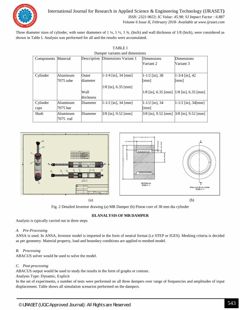
Three diameter sizes of cylinder, with outer diameters of 1 ¼, 1 ½, 1 ¾, (Inch) and wall thickness of 1/8 (Inch), were considered as shown in Table I. Analysis was performed for all and the results were accumulated.
TABLE I
Damper variants and dimensions Components Material Description Dimensions Variant 1 Dimensions
Variant 2 Dimensions Variant 3
Cylinder Aluminum 7075 tube
Outer diameter
Wall thickness
1-1/4 [in], 34 [mm]
1/8 [in], 6.35 [mm]
1-1/2 [in], 38 [mm]
1/8 [in], 6.35 [mm]
1-3/4 [in], 42 [mm]
1/8 [in], 6.35 [mm]
Cylinder caps
Aluminum 7075 bar
Diameter 1-1/2 [in], 34 [mm] 1-1/2 [in], 34 [mm]
1-1/2 [in], 34[mm]
Shaft Aluminum 7075 rod
Diameter 3/8 [in], 9.52 [mm] 3/8 [in], 9.52 [mm] 3/8 [in], 9.52 [mm]
(a) (b)
Fig. 2 Detailed Inventor drawing (a) MR Damper (b) Piston core of 38 mm dia cylinder
III. ANALYSIS OF MR DAMPER Analysis is typically carried out in three steps
A. Pre-Processing ANSA is used. In ANSA, Inventor model is imported in the form of neutral format (i.e STEP or IGES). Meshing criteria is decided as per geometry. Material property, load and boundary conditions are applied to meshed model.
B. Processing ABACUS solver would be used to solve the model.
C. Post-processing ABACUS output would be used to study the results in the form of graphs or contour. Analysis Type: Dynamic, Explicit In the set of experiments, a number of tests were performed on all three dampers over range of frequencies and amplitudes of input displacement. Table shows all simulation scenarios performed on the dampers.
International Journal for Research in Applied Science & Engineering Technology (IJRASET) ISSN: 2321-9653; IC Value: 45.98; SJ Impact Factor : 6.887
Volume 6 Issue II, February 2018- Available at www.ijraset.com
544 ©IJRASET (UGC Approved Journal): All Rights are Reserved
TABLE III
Amplitude and frequency inputs
Amplitude= 8mm Amplitude= 13mm Amplitude= 23mm
2Hz 2Hz 2Hz
4Hz 4Hz 4Hz
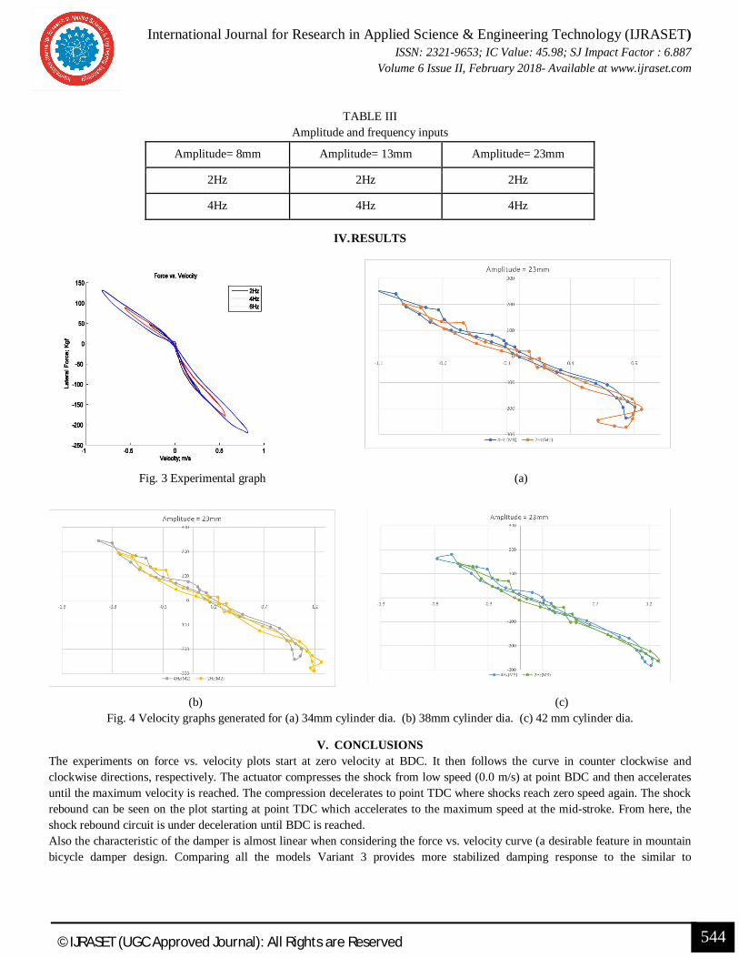
IV. RESULTS
Fig. 3 Experimental graph (a)
(b) (c) Fig. 4 Velocity graphs generated for (a) 34mm cylinder dia. (b) 38mm cylinder dia. (c) 42 mm cylinder dia.
V. CONCLUSIONS The experiments on force vs. velocity plots start at zero velocity at BDC. It then follows the curve in counter clockwise and clockwise directions, respectively. The actuator compresses the shock from low speed (0.0 m/s) at point BDC and then accelerates until the maximum velocity is reached. The compression decelerates to point TDC where shocks reach zero speed again. The shock rebound can be seen on the plot starting at point TDC which accelerates to the maximum speed at the mid-stroke. From here, the shock rebound circuit is under deceleration until BDC is reached. Also the characteristic of the damper is almost linear when considering the force vs. velocity curve (a desirable feature in mountain bicycle damper design. Comparing all the models Variant 3 provides more stabilized damping response to the similar to

International Journal for Research in Applied Science & Engineering Technology (IJRASET) ISSN: 2321-9653; IC Value: 45.98; SJ Impact Factor : 6.887
Volume 6 Issue II, February 2018- Available at www.ijraset.com
545 ©IJRASET (UGC Approved Journal): All Rights are Reserved
experimental test procedure also limiting the velocity in accordance to the experimental results concluding the optimistic behavior under three simulation data.
REFERENCES [1] Lazareva, T.G. and Shitik, I.G., "Magnetic and Magnetorheological Properties of Flowable Compositions Based on Barium and Strontium Ferrites and Iron
Oxides," Proceedings of the Society for Optical Engineering, Vol. 3040, pp. 185-189, March 1997. [2] Ashour, O.; Kinder, D.; "Manufacturing and Characterization of Magnetorheological Fluids,” Proceedings of the Society for Optical Engineering, Vol. 3040,
pp. 174-184. [3] Ashour, O., Rogers, C.A., and Kordonsky, W. "Magnetorheological Fluids: Materials, Characterization, and Devices," Journal of Intelligent Material Systems,
and Structures, Vol. 7, March 1996, pp. 123-130. [4] Carlson, J.D.; Catanzarite, D.M.; and St. Clair, K.A., "Commercial Magnetorheological Fluid Devices," International Journal of Modern Physics B, Vol. 10,
No. 23-24, pp. 2857-2865. [5] Kordonsky, W., "Elements and Devices Based on Magnetorheological Effect,"Journal of Intelligent Materials, Systems, and Structures, Vol. 4, pp. 65-69,
January 1996. [6] Bolter, R., and Janocha, H., "Design Rules for MR Fluid Actuators in Different Working Modes," Proceedings of the Society for Optical Engineering, Vol.
3045, pp. 148-159, March 1997. [7] Jolly, M.R., Carlson, J.D., and Munoz, B.C., "A Model of the Behavior of Magnetorheological Materials," Smart Materials and Structures, Vol. 5, No. 5, pp.
607-614, October 1996. [8] Soroush Sefidkar-Dezfouli, B.Sc., Azad University, 2009, Design, Simulation, and Fabrication of a Lightweight Magneto Rheological Damper [9] S. A. Bin Mazlan, “The behaviour of Magnetorheological fluid in squeeze mode,” Dublin city university, 2008. [10] N. B. Ekreem, “An investigation of Electromagnetic Rigenerated strong magnetic fields,” Dublin City University, 2009. [11] S. a Mazlan, N. B. Ekreem, and a G. Olabi, “Apparent stress–strain relationships in experimental equipment where magnetorheological fluids operate under
compression mode,” J. Phys. D. Appl. Phys., vol. 41, no. 9, p. 095002, May 2008. [12] M. H. Eltawahni, “Characterization and Finite Element analysis for soft magnetic materials used in automotive applications,” Dublin City University, 2006.
