8 design and construction of the uoit climatic wind tunnel · 8 design and construction of the uoit...
TRANSCRIPT

8 Design and Construction of the UOIT Climatic Wind Tunnel Gary M. Elfstrom and Greg L. Rohrauer Abstract The University of Ontario Institute of Technology (UOIT) climatic wind tunnel (CWT) is described from its genesis, through design and construction. The primary need of the CWT was to provide an independent, full test capability, for car and truck thermal operation testing in support of the automotive industry in Canada. Design and cost tradeoffs were conducted to maximize the test fidelity within the anticipated user vehicle spectrum. This led to the concept of a CWT with a moderate nozzle size to accommodate trucks and a large adjacent soak room to test very large vehicles such as highway coaches. Unique features include a 7-14.5m2 variable nozzle concept to enable a wide range of vehicle sizes and wind speed combinations, and a turntable with chassis dynamometer to enable vehicle tests at yaw. Fabrication of the CWT closed loop air circuit includes the use of thermally insulated custom designed welded steel sections in addition to modular insulated panels. The CWT is well into construction, with commissioning expected to be complete in early 2010. 8.1 Introduction
The of University of Ontario Institute of Technology (UOIT) climatic wind tunnel (CWT) is a key component of a major new initiative to aid indigenous Canadian automobile research and development. It is the centerpiece in the Automotive Centre of Excellence (ACE), funded largely by the Province of Ontario, with significant help from the Canadian Federal government. The investment is also supported by major contributions from the University itself and General Motors of Canada, the anchor tenant. It is part of a much larger re-investment initiative struck between General Motors and the Canadian Governments under the BEACON project, first announced in 2005. It was designed to help underpin the automotive manufacturing industry and its supplier base in Ontario by establishing an Automotive Innovation Network (AIN). ACE is at the center of this network. The specific need for the CWT was to provide automotive manufacturers (OEM’s) and Tier 1 suppliers with an independent test capability, to validate prototype car and truck thermal operation under a full range of climatic conditions. Traditionally, General Motors, as many of their competitors, have maintained outdoor cold weather test facilities in northern central Canada, within a 1000 Km radius of the automotive hub situated around Detroit. These are positioned at the very extremities of road networks leading into the northern communities. In an effort to expand and build on this expertise and bring the test and development activity indoors under highly replicable conditions operating throughout the year, the climatic test facility described was born from the needs and desires of 21st century automotive development. Aiolos Engineering Corporation, an international supplier of design, construction, and commissioning services of climatic and other facilities for global customers, has worked collaboratively with UOIT on all aspects of facility

- 2 -
realization, from test definition to design, construction, and subsequent commissioning. This paper will begin with an overview of the need for the CWT, then discuss tradeoff studies, concept development, key design and construction features and conclude with a status report of the site work. 8.2 UOIT CWT Genesis Support for vehicular development activities in Canada is both sparse and dispersed, with much of the equipment aging or designed for other purposes initially. A test and development facility within easy access and in proximity to an urban resource base dense with component and service suppliers was needed. The bulk of the automotive OEM and Tier 1 supplier base resides in Southern Ontario, With UOIT being next door to one of the largest manufacturers, General Motors of Canada, it was a logical choice to locate an Automotive Centre of Excellence (ACE). This is a model which has precedence with Tongji University in China, University of Stuttgart in Germany and RMIT in Australia. The typical climatic facility of an OEM can be specific to a class of vehicle or subset of development activity (example: drivability, emissions, fuel and lubricants, passenger cars, trucks). The volume of business in any such area specifically within Canada is in itself insufficient to support a highly specialized facility. The goal of the ACE CWT was to provide a modern, independent test capability, in an environment suitable for prototype and development vehicle tests, as well as university level research. Moreover, the proximity to the USA lends itself to serving the entire North American market, in particular as an independent “test house”. There are challenges when attempting to serve the entire range of automotive vehicles, from small cars to full size buses. This led to a market and a technical tradeoff study which were used to arrive at a cost-effective facility which would adequately serve the target markets. 8.3 Market Study The characteristic parameter which describes a CWT is the nozzle size and a survey of the North American CWT market showed predominance in the 5m2 size, with only a handful of CWT’s with a larger nozzle size, Figure 8.1. Further, the only automotive dynamic thermal test facility in Canada, the Imperial Oil All Weather Chassis Dynamometer which has a 5m2 nozzle, just ceased operations in 2009 after more than 30 years of fuels and lubricant work. There is a dearth of any suitable facilities, none within Canada, and few at all with large enough nozzle size for bus and large truck thermal testing in North America. Moreover, there are relatively few modern facilities overall, both within easy traveling distance while central to a metropolis (like Toronto). None of the existing CWTs within North America are independent from the OEMs and Tier 1 supplier companies. It was evident that aging test facilities were pressed into continued use for a lack of resources.

- 3 -
North American CWTs by Category
0
5
10
15
0 4 8 12 16 20
Nozzle size (m2)
Num
ber o
f fac
ilitie
sManufacturersSuppliers
Figure 8.1: North American CWT population by nozzle size.
8.4 Tradeoff Studies The capital and operating cost of running a CWT large enough to accommodate bus testing at relatively low wind speed while also accommodating car testing at high wind speed would be prohibitive, and so an extensive tradeoff study was made to examine cost-effectiveness of various alternative configurations. 8.4.1 Tradeoff Issues The table below summarizes the key tradeoff issues which were studied: No. Issue Positive Negative 1 Large nozzle size Extremely limited bus and
truck test capability in North America
Low usage may not justify capital or operating cost
2 Relatively high flow quality
Improved data fidelity Moderate capital cost
3 Large nozzle size plus high flow quality
• Even further improved data fidelity than with No.2
• Potential for aerodynamic testing
• High capital cost • High capital and
operating costs due to relatively high wind speed
4 Advanced dynamometer with individual belts in place of rolls
Improved underbody flow simulation
Extremely high capital cost
5 Moderate to high wind speed at lowest temperature
Improved test capability for high performance cars
High cooling system capital cost for low usage
6 Compact overhead return circuit instead of horizontal
• Lower thermal losses • Smaller building
footprint
• Moderately high installed fan power
• Capital cost increment

- 4 -
A wide variation of nozzle sizes test section configurations and wind speeds were examined, for example:
• 6.5m2/4.6m2 CWT for cars and SUV’s • 9.3m2/6.5m2/4.6m2 CWT for cars, SUV’s and trucks • Several CWT’s with max nozzle size greater than 10m2.
The end result of the tradeoff studies was:
• Full thermal testing, static and dynamic, of cars and SUV’s would be accommodated in a CWT facility with a nominal nozzle size of 9.3m2
• Full thermal testing of large trucks and buses would be accommodated using a larger nozzle size with a reduced wind speed
• Static thermal testing of large trucks and buses would be accommodated in two static test chambers. A related thermal chamber would accommodate Noise Harshness Vibration (NVH), with another for acoustic work.
• Provision for acoustic testing of cars at low wind speed. This would enable users to detect subtle changes in engine and transmission performance, particularly during starting and initial vehicle drive-away.
• Provision for aerodynamic testing of cars would be provided by including additional flow conditioning elements in the settling chamber and by including a turntable in the CWT test section which could accommodate a rolling road/balance in place of the conventional chassis dynamometer.
• The test section design was to be for interchangeable and serviceable test stations, protecting the investment for future upgrades while broadening the scope of market penetration.
• The ultimate goal set was to achieve a world class development windtunnel, commensurate with a university level research agenda, to achieve fully integrated thermo-aero measurements melded into a single test station.
8.4.2 Performance Summary A summary of the key nozzle size, wind speed and temperature simulation envelope for climatic testing is as follows:
Nozzle Size (m2) Wind Speed (kph) Temperature (°C) 9.3 and 7.0 0 to 80 -40 to -35
0 to 115 -35 to +10 -16 to 201 +10 to +60
7.0 -16 to 241 +25 to +60 In addition, there is provision for future aerodynamic testing by achieving higher wind speeds in the nominal and maximum nozzle sizes, given in the table below:
Nozzle Size (m2) Wind Speed (kph) Temperature (°C) 9.3 260 (max, continuous)
280 (intermittent, 10 minute) 25
13 230 (max, continuous) 241 (intermittent, 10 minute)
25

- 5 -
The above wind speeds will be attained with steady state temperature control dictated by cooling system capacity designed for thermal testing, with higher intermittent values possible. The range of humidity control will be according to the following table:
Temperature Range (°C) Relative Humidity Range (%) -20 to 0 50 to 80 0 to +5 10 to 80 +5 to +40 5 to 95 (at reduced heat load)
The baseline background out-of-flow noise level in the test chamber is:
Wind Speed (kph) Sound Pressure (dBA) 50 71 140 86
8.4.3 Flow and Thermal Quality Summary Flow, temperature and humidity uniformity requirements in the core region exclusive of the shear layer region are given in the following table:
Parameter Uniformity (σ) Distance downstream of nozzle exit (m)
Wind speed 1% of set point 0 Flow angularity 0.5° 1.5m Temperature 0.3°C 0 Humidity 0.5°C (dew point) 0
Wind speed, temperature and humidity stability requirements are given as follows: Parameter Stability Period of
fluctuation Time after transition
Wind speed ±0.5kph >10 sec <5 sec Temperature ±0.2°C at velocity > 48kph >10 min <2 min Humidity ±0.5°C (dew point) NA <10 min Wind speed, temperature tracking and transition requirements are stated in the following table:
Parameter Transition* rate
Transition* range
Remarks
Wind speed >15 kph/sec 0-100kph Overshoot <5% set point Temperature >0.8°C/min <12°C At 32-50°C Humidity >1%RH/min 20%RH At 25-95%RH
*For wind speed, the transition is in the form of a linear ramp, tracking the chassis dynamometer.

- 6 -
8.5 Key Facility Design Features 8.5.1 Circuit Airline The airline for the CWT was kept as compact as feasible, keeping in mind the following key goals:
• Test section length should be sufficient to allow limited thermal testing of long vehicles and to minimize the influence of axial static pressure gradient for aerodynamic testing
• Test section height and width sufficient to accommodate by-pass flow during idle/city testing and to accommodate a large solar simulation system
• Inclusion of suitable acoustic treatment to reduce the background noise level at low wind speeds
The test section configuration was chosen as follows:
• Overall dimensions: L20.1m x W13.5m x H7.5m • Nominal Jet length: 14.8m • Front wheel dynamometer axle located 3m from the nozzle exit plane • Turntable centerline: 6.1m from nozzle exit plane • Support provisions to add anechoic treatment to insulation panels • Mounting provision to incorporate adjustable collector • Structural support rail provisions for gantry (probe) in test chamber floor
Baseline acoustic treatment is in the following areas:
• Corners 1, 2 and 3 have acoustic treatment on the turning vanes • The main fan inlet and outlet has acoustic treatment • Helmholtz resonators (tunable) in return leg
The settling chamber has the following aerodynamic features:
• Main heat exchanger is located at the downstream end of a wide-angle diffuser, the high loss of which helps the diffuser to run full
• Aerodynamic flow quality in the largest nozzle test section will be achieved by having a moderate contraction ratio (5.54), two flow conditioning screens and provision for a deep-cell honeycomb flow straightener
• Idle-city testing is accommodated using a by-pass flap in the contraction together with re-injection into the test section at the upstream wall.
• A boundary layer scoop is used to thin the floor boundary layer immediately upon exiting the nozzle into the test chamber. A secondary distributed suction system is provisioned into the forward portion of the turntable
• The main fan, 4.85m diameter, has a rated power of 2500kW continuous, with excursions to 2900kW on a limited duty cycle basis to accommodate the wide range of operating conditions
• The heat exchanger provides up to 500kW heat absorption at -40°C, increasing to over 1800kW at -10°C. Performance at higher temperatures is designed to follow typical fan power input and duty cycle, 2100kW at ambient

- 7 -
Figure 8.2: Elevation view of CWT airline, corners labeled.
8.5.2 Variable Nozzle Concept The wide range of nozzle sizes was accommodated by a unique variable nozzle concept. While outwardly more complex than a multiple-nozzle concept, it offers the advantage of being able to achieve any prescribed intermediate nozzle size, maintain flow symmetry and have fast automated set-up time. Features which make the UOIT variable nozzle unique among contemporary CWT facilities include the following:
• Wide range of symmetric nozzle sizes (7.0-14.5m2) • Smooth, symmetrical flow contraction in both planes • Tangential flow at the nozzle exit.
Design of the adjustable nozzle was an iterative process, with the following goals:
• Achieve flow symmetry in both planes • Have an acceptable nozzle width/height aspect ratio over the full area range • Minimize the nozzle length in order to reduce the boundary layer growth on
the floor The resultant aerodynamic contour of the contraction has the following features:
• Contraction in the vertical plane starts first, in the settling chamber. The location was suitably downstream of the final flow conditioning screen to prevent interaction of the contraction flow field with the downstream screen
• Contraction in the horizontal plane then starts at the inflection point of the vertical contraction plane
• The contraction in the vertical plane ends at the inflection point of the horizontal contraction
• The final contraction to the desired test section area is achieved in the horizontal plane using a pair of flexible nozzle plates
• Heated Inflatable seals are used at the plate edge junctions
The dimensions of the key nozzle sizes are given in the following table:
1
2 3
4

- 8 -
Nozzle Size (m2) Width (m) Height (m) 14.5 (bus climatic) 5.0 2.9 13.0 (aero) 4.5 2.9 9.3 (climatic) 3.2 2.9 7.0 (H.S. climatic) 2.4 2.9
The aspect ratio W/H of the 13m2 nozzle, about 1.55, should be adequate for moderate yaw angle aerodynamic testing. The airline geometry was optimized for minimum static pressure gradient with an initial fixed collector size set to the 13m2 nozzle opening. The upper aerodynamic surface of this nozzle assembly is a rigid ceiling plate structure, which starts at the end of the vertical plane contraction, while the bottom surface is the test section steel floor. The entire adjustable portion of the nozzle is contained within a rigid portal frame assembly. This portal reacts the loads associated with the sidewall flexible plate positioning jack system. All jacks are electrically driven and were designed to adjust the nozzle width from 2.4 to 5 meters, in under 5 minutes.
Figure 8.3: Test section showing adjustable nozzle at 7m2, and 13m2 setting with yaw. There is provision to accommodate thermodynamic testing of very large vehicles such as Class 8 trucks and buses by providing a form of “blockage relief”:
• The flexible sidewalls can extend outwards beyond the nominal maximum to provide a direct nozzle area of 14.5m2 with a slightly divergent flow
• The rigid ceiling plate can lift upwards a maximum of 1.5m parallel to the floor using four jacks, which allows the flow from the end of the fixed contraction to begin diverging vertically well ahead of the vehicle. This provides a canopy to direct flow
• Alternately, extremely long vehicles like rear engine highway coaches can be inserted under the “canopy” to form a large annular flow field around the vehicle for better measurements at the rear.

- 9 -
Figure 8.4: Test section with adjustable nozzle at 5m width and nozzle ceiling raised.
8.5.3 Boundary Layer Removal System A 5.25m wide scoop-type boundary layer removal system at the nozzle exit has been designed to reduce the floor boundary layer displacement thickness at wind speeds greater than 90kph, to about 6mm at the forward chassis dynamometer roll axis location. The flow extracted by the scoop is returned to the circuit at the front of the test section, re-injected at the two corners. Additional distributed suction over perforated floor plate on the turntable leading edge will be capable of further reducing the boundary layer thickness. 8.5.4 Turntable and Chassis Dynamometer Another unique feature of the UOIT CWT is a “4-wheel independent” chassis dynamometer with yaw capability. The test section floor is a steel fabrication supporting a 11.7m diameter turntable with a cut-out that accommodates a chassis dynamometer unit. The cut-out has been designed for future insertion of a rolling road / balance assembly with a secondary boundary layer suction system for aerodynamic testing. The turntable and chassis dynamometer can be repositioned 180°, yaw range ±30°. The 180° placement permits positioning the fixed rolls at the rear (9.2 meters behind nozzle exit plane), and with closest approach of the moveable rolls allows for long wheelbase tandem axle vehicle testing, like highway coaches:
• Basic fixed front rolls, moveable rear rolls for FWD, RWD and AWD cars • Fixed front rolls, single axle rear wheel drive trucks • Vehicle yaw positioning for either thermal or aerodynamic testing
The chassis dynamometer is floated on air bearings during a change in yaw position, synchronously driven by the turntable, which in turn is supported on roller bearings in the steel floor. There is provision to interchange the chassis dynamometer with a

- 10 -
balance/rolling road assembly. The chassis dynamometer can be lowered by 1 meter into the basement and moved on its air bearings to an adjacent room and parked. The rolling road would then be moved from its parking spot in the basement to the test section, raised and inserted into the turntable. Electrical and mechanical connections are all designed as “plug-in”. A summary of the key performance features of the chassis dynamometer are given in the following table:
Feature Value or Range Configuration 2WD and 4WD Individually powered rolls Power Front 197/168kW (motoring/absorbing)
Rear 197/168kW (motoring/absorbing) Tractive effort Front 7300N @ 400rpm & 187kW
Rear 7300N @ 400rpm & 187kW Speed Base 92kph
Maximum 250kph Rolls Diameter 1.219m
Face width 0.55m Spacing (inside) 1.04m Rear roll travel 4.24m Closest approach 1.35m (tandem axle position) Weight limit 9100 kg/axle
The chassis dynamometer includes an automatic floor track and side roll cover system with a moveable central inspection port carrying a remotely controlled thermal imaging camera. A central inspection walkway is accessible via stairs from below. 8.5.5 Test Techniques The solar simulation system exhibits full diurnal function with azimuth and altitude automatically controlled by a combination of articulated lamp positioning and intensity control. It has a full spectrum capability with vertical and bi-axial movement to accommodate different vehicle sizes and solar incidence requirements. A summary of the capabilities is given in the following:
Parameter Value or description Target Size L6.5m x W2.4m
Location 1.2m above test section floor Spectrum ASTM Std E-892 Lamps (21) Metal halide
Intensity Maximum 1200kW/m2
Minimum 600kW/m2
Uniformity ±10% Stability ±5%
Incidence Minimum 0° (normal to floor) Maximum 52.5°
The solar system assembly can be raised up in order to accommodate tall vehicles in the test chamber or when not needed. Figure 8.5 illustrates the arrangement. A similar setup, without full movement system, exists in the large static test cell.

- 11 -
Figure 8.5: Test section with solar simulation system.
A frontal rain simulation system located at the nozzle exit consists of an array of up to 12 nozzles of in various sizes as needed to provide adequate coverage of a given vehicle. The system is designed for 150kph at 20°C but will operate as low as -5°C to perform freezing rain tests. Figure 8.6 illustrates a similar system from another CWT.
Figure 8.6: Example of frontal rain system. There are two configurations of snow simulation possible: frontal and overhead. In both cases, snow guns are used to create the snow, as shown in the following table:
Snow type Features Frontal Snow gun automatically inserts into settling
chamber contraction Overhead Two snow guns located over the contraction
outlet Wind speed range 50kph to 100kph Temperature range -30°C to -10°C
The CWT is designed to accommodate hydrogen (H2) powered vehicle testing:
• H2 is plumbed into the CWT from a trailer located outside and bypasses the fuel tank, directly to an engine or fuel cell (durability test)
• Vehicle is H2 fueled outside, and tested in chamber • Safety: appropriate electrical class codes are followed, including a separate
purge system for the ceiling area • Fire fighting: Supersonic water misting system in the test section, and vehicle
on-board fire extinguishers, water sprinklers otherwise

- 12 -
Additionally, high power outlets are available for plug-in hybrid and electric vehicles. 8.5.6 Ancillary Systems The CWT has the following ancillary systems included in the design: System Features Purge System Complete CWT circuit volume air change in 5 minutes, split
into two subsystems: • Upper system for lighter-than-air fuels, e.g. hydrogen • Lower system for heavier-than-air fuels, e.g. gasoline
Exhaust Extraction System
• Single and dual exhaust capability • 8.5 liter, 400hp engine rated
Make-Up Air System • Maintains positive test section pressure • High performance drying system for humidity control
Vehicle Starting Power 200 amp for 12V-DC and 24V-DC Radiator Pressure Fill System
Two independent systems capable of charging the vehicle from a pressurized vessel
Gas Tank and Differential Cooling
Cooling water system to provide cooling during high load tests
Refrigerant Charging System
Two charging systems, one for R134A or equivalent, the other for CO2. Capability to pull a vacuum once refrigerant has been reclaimed.
Tire cooling Vortex tubes 8.5.7 Control and Data Acquisition A test automation system has integrated test facility device control, test parameter control and test technique synchronization, in fully automatic and manual modes:
• Test facility device: o Nozzle setting o Boundary layer control o Vehicle exhaust o Makeup air o Purge air
• Test parameter o Wind speed o Air temperature o Humidity
• Test techniques o Chassis dynamometer including wind speed tracking o Solar simulation o Rain simulation o Snow simulation
• Vehicle ancillary devices o Fuel tank fill and cooling systems o Differential cooling system o Tire cooling system o Window icing system o Vehicle power and starting
• Safety and emergency: fire suppression, emergency lighting, etc.

- 13 -
The automation system also records data relevant to the test facility and parameter control. Vehicle data acquisition is via individual on-board data systems, networked to the facility. 8.5.8 Associated Test Chambers A unique cluster of soak rooms and a vehicle transfer area are located adjacent to the CWT and the main vehicle entrance area. The soak rooms have the capability for soaking and performing vehicle evaluations, including cold start, extended idles, and hot soaks under controlled temperature and humidity conditions. Heating and cooling systems are independent from that used in the CWT. A summary of this cluster is given in the following table:
Room or Area Parameter Value or Description Soak Room No.1 (static test cell)
Size L20m x W6m x H5.5m Vehicles One standard bus, or three large SUV’s Temperature and humidity
Identical range to CWT
Chassis dynamometer
4WD eddy-current type for idling warm-up, intermittent mileage accumulation or short full power
Solar simulation Similar target area as CWT Exhaust extraction Two ports to accommodate 8.5 liter, 300
kW engine Provisions Emissions dynamometer basement
Soak Room No.2 Size L9m x W6.4m x H5.6m
Vehicles One large SUV, or 2 small cars
Temperature and humidity
Identical range to CWT
Exhaust Extraction Two ports to accommodate 8.5 liter, 300 kW engine
Transfer Room Size L6.4m x W6.4m x H5.6m Thermal Dry air conditions maintained
8.6 Facility Construction The CWT closed loop circuit is essentially constructed from two types of fabrication:
• Custom designed welded steel sections, with sprayed on external foam insulation with a minimum rating of R18. This applies to the circuit from the collector all the way around to the nozzle exit. In addition, the entire test section floor is an insulated steel fabrication.
• Modular insulated panels with supporting steel superstructure. This applies to the test section plenum, soak rooms and transfer area, plus shaker test cells.
The CWT is integrated with the ACE engineering building at UOIT – see Figure 8.7. The core areas include the following features:
• Secure gated compound/yard • Secure client and personnel entrance • Vehicle entrance/wash-up area

- 14 -
• Basement prepared for future interchange of chassis dynamometer with balance/rolling road assembly
• Large static test cell, soak room, transfer hall • Vehicle prep bays with instrumentation shop • Machine shop, control rooms, storage, administration area • Multi-Axis Shaker Table (MAST) Test Cell
o Size: L9m x W8.8m x H5.1m o Hemi-Anechoic treatment: 150 Hz cut-off frequency o 2m diameter table, ~ level with floor (actuators in basement)
• 4-Post Climatic Test Cell o Size: L9m x W7.2m x H5.6m o Temperature, humidity controlled – same as CWT o Fabricated from modulator insulated panels o 4500kg rated 4-post hydraulic vehicle shaker o Drive-on wheel pans (actuators in basement) o Automatic positioning system
Figure 8.7: Plan view of building showing CWT and related test areas.
Transfer Hall
Soak Room
Control Room
MAST Test Cell
4-Post Test Cell
Vehicle Entrance
Vehicle Hoist Bays
Machine Shop
Instrumentation Lab
Wind tunnel Airline
Large Static Cell
Turning Vane Storage
Control Rooms
Air Lock

- 15 -
Figure 8.8: Section view of UOIT windtunnel, general arrangement with soak room.
8.7 Status Report 8.7.1 Construction Site preparation commenced in October 2007 to clear the land, and build a retaining wall around the campus storm water management pond upon which the facility abuts. This was timed with the winter freeze-up. After a hiatus, excavation and pile driving for the fan portal frame and pouring of deep footings underlying the dynamometer base, shaker test cells, and other building areas re-commenced in April 2008. At this writing, August 2009, the airline is in place except for the moveable turning vanes situated in corner one which provides vehicle access to the plenum. Erecting the building and airline has proceeded in stages, beginning with the CWT basement and settling chamber, followed by corners 4 and 3 in that order; the building construction then follows to envelope the airline. The dynamometer assembly was hoisted into the basement as a single unit during March 2009, prior to constructing the upper building level in that area. Over the summer of 2009 the upper portion of the airline (return leg) and fan assembly was installed, permitting subsequent placement of the roof deck. Building and windtunnel mechanical systems, are proceeding in parallel, with major elements like the cooling towers, main chillers, air handling units, heavy electrical transformers and switchgear hoisted in place prior to erecting the building around them. The balance of the facility, accommodating the shaker test cells, soak rooms, shops and support areas, are also well advanced. Concrete for floors 4 and 5, plus the mechanical penthouse supporting laboratories and offices, remains to be poured. Figures 8.9 through 8.13 depict key design features. 8.7.2 Concluding Remarks Since 2004, the UOIT Automotive Center of Excellence (ACE) has been in the planning, with design development carried through 2005-07. By the time the facility turns operational in 2010, approximately $CAD 100M will have been spent creating

- 16 -
an automotive climatic simulation facility that sets a world benchmark. The thrust is towards achieving a fully integrated aero-climatic development instrument for simultaneously gathering thermal and aerodynamic performance measurements on road vehicles. Fully integrated vehicular thermal-aero development work on a 1:1 scale, one of the last bastions of automotive test simulation, is now on its way towards being surmounted.
Figure 8.9: Independent 4WD chassis dynamometer undergoing shop tests.
Figure 8.10: Air circuit elements and main fan being assembled on site.
- 17 -
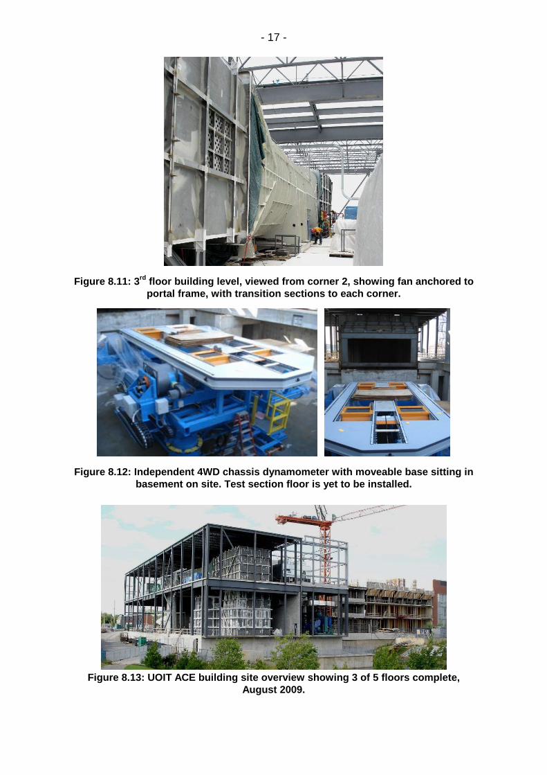
Figure 8.11: 3rd floor building level, viewed from corner 2, showing fan anchored to portal frame, with transition sections to each corner.
Figure 8.12: Independent 4WD chassis dynamometer with moveable base sitting in basement on site. Test section floor is yet to be installed.
Figure 8.13: UOIT ACE building site overview showing 3 of 5 floors complete,
August 2009.