860 ieee transactions on power delivery, vol. … wear... ·...
TRANSCRIPT

860 IEEE TRANSACTIONS ON POWER DELIVERY, VOL. 29, NO. 2, APRIL 2014
A Low-Wear Onload Tap Changer Diverter Switch forFrequent Voltage Control on Distribution NetworksDaniel J. Rogers, Member, IEEE, Tim C. Green, Senior Member, IEEE, and Richard W. Silversides, Member, IEEE
Abstract—This paper presents a fast mechanical diverter switchdesign suitable for new “arcless” hybrid onload tap-changingsystems. In such systems, arcing at contact separation and contactclosure is almost completely eliminated by the inclusion of al-ternate current paths incorporating semiconductor devices. Thisallows the use of compact, air-insulated mechanical contacts thatdo not need to withstand significant arc erosion or provide arcquenching. As a result, the moving mass and the drive system forthe switch may be dramatically reduced in size, leading to lowinertia of the moving parts and resulting in very rapid operationtimes. An integrated, high-torque, low-mass permanent-magnetactuator is presented that provides detent (unpowered) contactforce coupled with a cantilever spring contact system sized for an11-kV 2-MVA onload tap changer. The design delivers operationtimes of under 20 ms and is capable of sustaining more than
operations. The complete design is experimentally verifiedunder representative electrical conditions, and contact wear levelscomparable to pure mechanical (zero current) operation aredemonstrated.
Index Terms—Arc discharges, contacts, permanent-magnet ma-chines, power distribution, switches, switchgear, voltage control.
I. INTRODUCTION
T HE HYBRID onload tap changer (OLTC) combines me-chanical switching elements and power semiconductor
devices to provide a balance in performance across a numberof metrics when compared to purely mechanical (or “classic”)OLTCs and OLTCs based upon power semiconductor devicesalone. Hybrid OLTCs typically employ mechanical contacts tocarry the load current when operating in the steady state (i.e.,while not performing a tap change), resulting in very low con-duction losses and a high tolerance of network fault currents.When a tap change is required, the hybrid OLTC employs alow-rated power-electronic circuit to divert current out of themain current path and into an alternate thyristor-based pathwhich is then used to commutate the current into another trans-former tap. Once the current has been fully transferred to the
Manuscript received April 15, 2013; revised June 28, 2013; accepted July01, 2013. Date of publication August 01, 2013; date of current version March20, 2014. This work was supported by a UK EPSRC Doctoral Training Awardand was conducted partly within the Supergen FlexNet programme. Paper no.TPWRD-00441-2013.D. J. Rogers is with the Institute of Energy, School of Engineering, Cardiff
University, Cardiff CF24 3AA, U.K. (e-mail: [email protected]).T. C. Green and R. W. Silversides are with the Electrical and Electronic
Engineering Department, Imperial College London, London SW7 2AZ, U.K.(e-mail: [email protected]; [email protected]).Color versions of one or more of the figures in this paper are available online
at http://ieeexplore.ieee.org.Digital Object Identifier 10.1109/TPWRD.2013.2272335
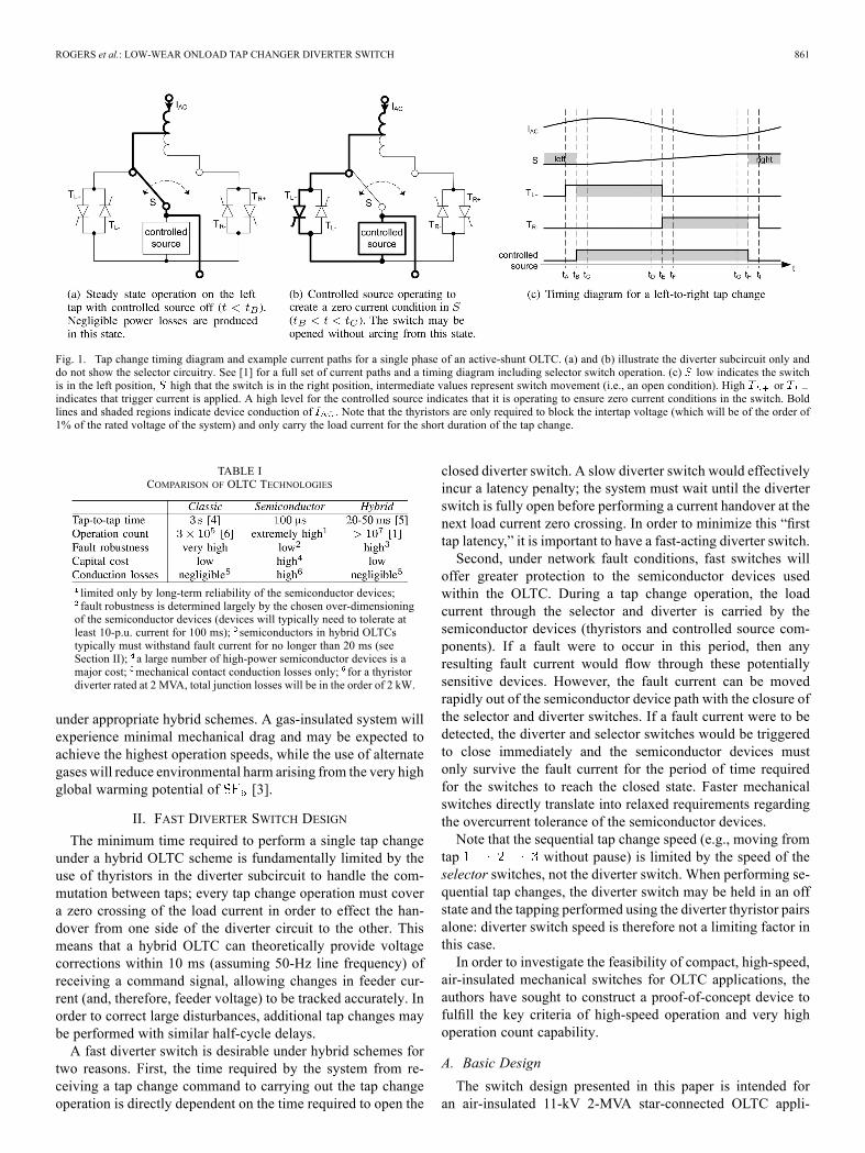
new tap, a mechanical switch is closed to bypass the thyristorsand return the system to steady-state operation. This process isillustrated in Fig. 1 for an active-shunt-type hybrid OLTC [1].An important future hybrid-OLTC application will be in the
support of high levels of electric-vehicle (EV) charging on thedistribution network, perhaps coupled with a high penetrationof intermittent distributed generation [e.g., photovoltaics (PV)].Both EV charging and PV generation can lead to large andfrequent variations in feeder current, due to highly correlatedEV charging profiles and/or local cloud shadowing of many PVinstallations [2]. Due to the low ratio of low-voltage (LV)lines, voltage control based on reactive compensation is notpractical, and direct voltage control in the form of OLTCs willbe necessary to maintain supply within voltage limits withoutresorting to comparatively expensive cable upgrades. In allcases, the speed of response, service interval, lifetime, robust-ness, and power losses are key measures of OLTC performance.Table I summarizes the attributes of classic, semiconductor-
only, and hybrid OLTC technologies. In general, the semicon-ductor-only OLTC may operate extremely quickly and incursno wear penalty per operation; however, as one or more semi-conductor devices must carry the load current continuously, thesystem is vulnerable to and must be dimensioned to cope withnetwork fault events (i.e., overcurrent) and incurs relatively highoperating power loss. The classic OLTC relies on mechanicalcontact movement to perform tap changes and is therefore rel-atively slow; however, due to the very low path resistance, thelosses are negligible and the system is robust against networkfaults. A major factor contributing to the limited lifetime ofthe classic OLTC is the heavy arcing that inevitably occurs atevery tap change operation: this places a fundamental limit onthe number of operations that the system may perform beforerequiring replacement of the contacts.The hybrid OLTC may be expected to deliver much greater
contact lifetime when compared to the classic OLTC becausecontact arcing is eliminated by the operation of an auxiliarycircuit that removes current from the mechanical contacts be-fore they are opened (this process is explored in detail in [1]).An additional benefit of the elimination of arcing is an increasein operating speed relative to the classic OLTC. This is a re-sult of a reduction in the contact mass required in the switchdue to the elimination of arc-induced erosion of the contact sur-faces. Since contact erosion is no longer a concern, the chiefdesign constraint dictating contact size becomes current han-dling capability and so the switch may be made smaller andlighter. Furthermore, as no arc is drawn at contact separation,the arc quenching properties of oil or are not required. Air-or -insulated diverter switches therefore become possible
This work is licensed under a Creative Commons Attribution 3.0 License. For more information, see http://creativecommons.org/licenses/by/3.0/
ROGERS et al.: LOW-WEAR ONLOAD TAP CHANGER DIVERTER SWITCH 861
Fig. 1. Tap change timing diagram and example current paths for a single phase of an active-shunt OLTC. (a) and (b) illustrate the diverter subcircuit only anddo not show the selector circuitry. See [1] for a full set of current paths and a timing diagram including selector switch operation. (c) low indicates the switchis in the left position, high that the switch is in the right position, intermediate values represent switch movement (i.e., an open condition). High orindicates that trigger current is applied. A high level for the controlled source indicates that it is operating to ensure zero current conditions in the switch. Boldlines and shaded regions indicate device conduction of . Note that the thyristors are only required to block the intertap voltage (which will be of the order of1% of the rated voltage of the system) and only carry the load current for the short duration of the tap change.
TABLE ICOMPARISON OF OLTC TECHNOLOGIES
limited only by long-term reliability of the semiconductor devices;fault robustness is determined largely by the chosen over-dimensioningof the semiconductor devices (devices will typically need to tolerate atleast 10-p.u. current for 100 ms); semiconductors in hybrid OLTCstypically must withstand fault current for no longer than 20 ms (seeSection II); a large number of high-power semiconductor devices is amajor cost; mechanical contact conduction losses only; for a thyristordiverter rated at 2 MVA, total junction losses will be in the order of 2 kW.
under appropriate hybrid schemes. A gas-insulated system willexperience minimal mechanical drag and may be expected toachieve the highest operation speeds, while the use of alternategases will reduce environmental harm arising from the very highglobal warming potential of [3].
II. FAST DIVERTER SWITCH DESIGN
The minimum time required to perform a single tap changeunder a hybrid OLTC scheme is fundamentally limited by theuse of thyristors in the diverter subcircuit to handle the com-mutation between taps; every tap change operation must covera zero crossing of the load current in order to effect the han-dover from one side of the diverter circuit to the other. Thismeans that a hybrid OLTC can theoretically provide voltagecorrections within 10 ms (assuming 50-Hz line frequency) ofreceiving a command signal, allowing changes in feeder cur-rent (and, therefore, feeder voltage) to be tracked accurately. Inorder to correct large disturbances, additional tap changes maybe performed with similar half-cycle delays.A fast diverter switch is desirable under hybrid schemes for
two reasons. First, the time required by the system from re-ceiving a tap change command to carrying out the tap changeoperation is directly dependent on the time required to open the
closed diverter switch. A slow diverter switch would effectivelyincur a latency penalty; the system must wait until the diverterswitch is fully open before performing a current handover at thenext load current zero crossing. In order to minimize this “firsttap latency,” it is important to have a fast-acting diverter switch.Second, under network fault conditions, fast switches will
offer greater protection to the semiconductor devices usedwithin the OLTC. During a tap change operation, the loadcurrent through the selector and diverter is carried by thesemiconductor devices (thyristors and controlled source com-ponents). If a fault were to occur in this period, then anyresulting fault current would flow through these potentiallysensitive devices. However, the fault current can be movedrapidly out of the semiconductor device path with the closure ofthe selector and diverter switches. If a fault current were to bedetected, the diverter and selector switches would be triggeredto close immediately and the semiconductor devices mustonly survive the fault current for the period of time requiredfor the switches to reach the closed state. Faster mechanicalswitches directly translate into relaxed requirements regardingthe overcurrent tolerance of the semiconductor devices.Note that the sequential tap change speed (e.g., moving from
tap without pause) is limited by the speed of theselector switches, not the diverter switch. When performing se-quential tap changes, the diverter switch may be held in an offstate and the tapping performed using the diverter thyristor pairsalone: diverter switch speed is therefore not a limiting factor inthis case.In order to investigate the feasibility of compact, high-speed,
air-insulated mechanical switches for OLTC applications, theauthors have sought to construct a proof-of-concept device tofulfill the key criteria of high-speed operation and very highoperation count capability.
A. Basic Design
The switch design presented in this paper is intended foran air-insulated 11-kV 2-MVA star-connected OLTC appli-

862 IEEE TRANSACTIONS ON POWER DELIVERY, VOL. 29, NO. 2, APRIL 2014
Fig. 2. CAD wireframe rendering of the switch. Top view of the switch in theleft-on position showing the deflection of the cantilever contact and the resultingdisplacement of the magnets from the minimum energy position. See Fig. 7 foran alternative view of the switch. The pole and magnet radii are equal
60 mm) and the contact radius 45 mm. The pole pitch angleis BAC and in this diagram, a magnet pitch angle of isillustrated (the selection of magnet pitch is discussed in Section II-B).
cation (nominal phase current of 100 A). The switch is anintegrated three-phase, double-throw design driven by a perma-nent-magnet actuator and uses cantilever-spring contacts. Thistype of design has low mechanical complexity and low inertia,allowing for reliability at high operation counts and very highactuation speed. A particular advantage of the double-throwdesign is that the switch is guaranteed to pass through the offstate during operation (break before make), a fundamentalbehavior required by all OLTC schemes. The basic mechanicaldesign of the switch is illustrated in Fig. 2. The importantdesign decisions and tradeoffs are discussed in the followingsections.
B. Magnetic Design
A principle design constraint is that the switch should remainin a stable state should a failure in the actuation system (powersupply, drive electronics, sensing systems, etc.) cause the actu-ator to become disabled. This will enable the OLTC to continuefunctioning on the current tap but without the ability to performfurther tap change operations. Thus, a detent torque should beprovided in the closed states independent of any external powersupply. In order to meet the speed-of-operation target, a hightorque-to-inertia ratio is also desirable. A permanent-magnet ac-tuator design employing high-strength rare-earth magnets canmeet both of these criteria.Some aspects of the magnetic design are visible in Fig. 2. A
set of six c-cores are regularly spaced at angles of 20 about thecentral axis of the switch. The cores provide a low reluctance
path for the flux driven by the coil wound around the rear sec-tion. The core flux interacts with the field created by a set offour permanent magnets, also regularly spaced and fixed intothe armature that passes through the gap in the cores, and ori-ented in alternating magnetic direction parallel to the armaturecentral axis. In the following discussion the c-cores plus coilsare referred to as “poles” and the armature permanent magnetsare referred to as “magnets.”When the poles are appropriately energized, it is possible to
generate motive torques of large magnitude in either direction.The armature is not used as a flux path and may therefore beconstructed of a lightweight plastic, resulting in a low inertiadesign. Crucially, when the poles are unenergized (i.e., zero cur-rent is flowing in the coils), an attractive force between magnetsand poles will still be present, allowing a detent torque to bemaintained without external power. This is often a special re-quirement for electromagnetic actuators for electrical switchingsystems, for example, [7].A tradeoff is evident in the choice of the magnet pitch angle.
A magnet pitch that is equal to the pole pitch produces thegreatest peak contact force in the unenergized state since eachmagnet may simultaneously be positioned in a high-force statewhen displaced from the nearest pole gap. However, this pitchproduces the maximum torque ripple in the energized state sinceno torque may be produced when every magnet is positionedcentrally in a pole gap. Conversely, a three-quarter magnet-polepitch (i.e., where ) produces minimumtorque ripple in the energized state but very little static contactforce may be generated in the unenergized state.A conceptually simple scheme to generate high actuation
torque in the energized state is to set the magnetization direc-tion of each pole so that the pole closest to any given magnetexerts an attractive force if the magnet lies behind the pole inthe desired direction of travel. Similarly, if the closest magnetlies ahead of the pole, the pole magnetization direction is setsuch that it repels the magnet from the gap. This procedure isrepeated for each pole and determines the coil drive currentpattern to provide high actuation speed while requiring a lownumber of drive switching transitions per actuation. A resultof this simple algorithm (coupled with the alternating magnetmagnetization direction) is that the second-closest pole to anygiven magnet is magnetized in a direction such that it construc-tively adds to the force in the desired direction of travel. Thisalgorithm is valid for any magnet-pole pitch.Fig. 3 presents the results of multiple static 2-D finite-ele-
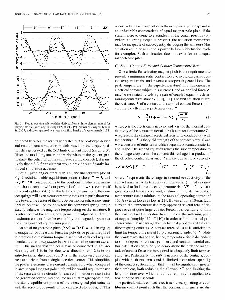
ment simulations representing the magnetic design of Fig. 2 atvarious armature displacements and for varying magnet pitchangles. The relationship between static contact force in the un-energized state and torque ripple in the energized state is clearlyvisible. This 2-D analysis [8] models a flattened version of theactual system: the depth of the model was set equal to that usedin the design (20 mm) but the nonparallel nature of the magnetsand poles was not modelled (i.e., the magnets and poles wereconsidered to be parallel through their depth). A 3-D finite-ele-ment simulation would capture the curvature of the real system,and enable the modelling of the out-of-plane nature of the c-coremagnetic circuit but at the cost of much greater computationalcomplexity. As discussed in Section IV-D, good agreement was
ROGERS et al.: LOW-WEAR ONLOAD TAP CHANGER DIVERTER SWITCH 863
Fig. 3. Torque-position relationships derived from a finite-element model forvarying magnet pitch angles using FEMM v4.2 [9]. Permanent-magnet type isSmCo27, and poles operated to a saturation flux density of approximately 1.2 T.
observed between the results generated by the prototype deviceand results from simulation models based on the torque-posi-tion data generated by the 2-D finite-element model (i.e., Fig. 3).Given the modelling uncertainties elsewhere in the system (par-ticularly the behavior of the cantilever spring contacts), it is un-likely that a 3-D finite element would provide significantly im-proved simulation accuracy.For all pitch angles other than 15 , the unenergized plot of
Fig. 3 exhibits stable equilibrium points (where and) corresponding to the positions in which the arma-
ture should remain without power: Left-on , center-off(0 ), and right-on (20 ). In the left and right positions, the con-tact springs will exert a counter torque that acts to push the arma-ture toward the center of the torque-position graph. A new equi-librium point will be found where the combined spring torqueexactly balances the magnetic torque acting on the armature. Itis intended that the spring arrangement be adjusted so that themaximum contact force be exerted by the magnetic system atthe spring-magnet equilibrium point.An equal magnet-pole pitch ( in Fig. 2)
is unique for two reasons. First, the pole-drive pattern requiredto produce the maximum torque is such that each coil requiresidentical current magnitude but with alternating current direc-tion. This means that the coils may be connected in anti-se-ries (i.e., coil 1 is in the clockwise direction, coil 2 is in theanti-clockwise direction, coil 3 is in the clockwise direction,etc.) and driven from a single electrical source. This simplifiesthe power-electronic drive circuit considerably when comparedto any unequal magnet-pole pitch, which would require the useof six separate drive circuits for each coil in order to maximizethe generated torque. Second, for an equal magnet-pole pitch,the stable equilibrium points of the unenergized plot coincidewith the zero-torque points of the energized plot of Fig. 3. This
occurs when each magnet directly occupies a pole gap and isan undesirable characteristic of equal magnet-pole pitch: if thesystem were to come to a standstill in the center position (0 )(where no spring torque is present), the actuation mechanismmay be incapable of subsequently dislodging the armature (thissituation could arise due to a power failure midactuation cyclefor example). Such a situation does not exist for an unequalmagnet-pole pitch.
C. Static Contact Force and Contact Temperature Rise
One criteria for selecting magnet pitch is the requirement toprovide a minimum static contact force to avoid excessive con-tact temperature rise under worst-case operating conditions. Thepeak temperature (the supertemperature) in a homogeneouselectrical contact subject to a current and an applied forcemay be estimated by solving a pair of coupled equations deter-mining contact resistance [10], [11]. The first equation relatesthe resistance of a contact to the applied contact force , in-cluding the effect of supertemperature
(1)
where is the electrical resistivity and is the the thermal con-ductivity of the contact material at bulk contact temperature ,represents the change in electrical resistivity conductivity withtemperature. is the yield strength of the contact material andis a constant of order unity which depends on contact materialand shape. The second equation relates the supertemperature tothe voltage drop across the contact; this voltage is a product ofthe effective contact resistance and the contact load current
(2)where represents the change in thermal conductivity of thecontact material with temperature. Equations (1) and (2) maybe solved to find the contact temperature rise at agiven contact force and current, as shown in Fig. 4. The contacttemperature rise is minimal at the nominal operating current of100 A even at forces as low as 2 N. However, for a 10-p.u. faultcurrent, the temperature rise may approach several tens of de-grees even at quite large contact forces. It is desirable to limitthe peak contact temperature to well below the softening pointof copper (roughly 180 C [10]) in order to limit thermal pro-cesses which may damage the mechanical properties of the can-tilever spring contacts. A contact force of 10 N is sufficient tolimit the temperature rise at 10-p.u. current to under 40 . Notethat contact resistance and, hence, temperature rise is dependentto some degree on contact geometry and contact material andthis calculation serves only to demonstrate the order of magni-tude of contact force that is required to adequately limit temper-ature rise. Particularly, the bulk resistance of the contacts, cou-pled with the thermal mass and the limited dissipation capabilityof the contact system, imply that will be significantly greaterthan ambient, both reducing the allowed and limiting thelength of time over which a fault current may be applied to afew hundred milliseconds.A particular static contact force is achieved by setting an equi-
librium contact point such that the permanent magnets are dis-

864 IEEE TRANSACTIONS ON POWER DELIVERY, VOL. 29, NO. 2, APRIL 2014
Fig. 4. Contact temperature rise against contact force for copper contacts atvarious currents. The bulk contact temperature is C and 1.
placed some distance from their minimum energy position bythe action of cantilever contacts. The equilibrium contact pointis formed when the spring torque generated by the cantilevercontacts exactly balances the magnetic torque of the actuator. Ifis the contact radius (see Fig. 2, 45 mm in this
design), the contact force per phase may be calculated from
(3)
for a magnet pitch angle of 18 , the peak static magnetic torquefrom Fig. 3 is 2.08 Nm, giving 15.4 N. Note that (3)contains a factor of 1/3 due to the use of three cantilever springs.The design of the cantilever contacts should be such that the
equilibrium point is at the maximum static magnetic torque po-sition. From the desired contact deflection and a known peakstatic contact force, the required cantilever thickness may be es-timated from the Euler–Bernoulli beam equation [12] as
(4)
where is the Young’s modulus of the cantilever material andand are the length and height of the cantilever, respectively (33and 19mm in this design). For this design, the springs were con-structed from a beryllium copper strip to provide high electricalconductivity, backed by a carbon (spring) steel strip to providethe majority of the spring force and the required mechanical ro-bustness over many operating cycles.
III. SWITCH MODELING
The torque-position information of Fig. 3 may be used as aninput to a lumped-mass mechanical model representing the me-chanical system of Fig. 2, described by
(5)
where describes the kinetmatic torque-position rela-tionship of Fig. 3 and describes the forces deliveredby the cantilever spring contacts. The contact linear positionis found from the rotational position of the armature via
the contact radius . The angular velocity of the armature
Fig. 5. Contact forces at switch closure, is the frictionalforce between contacts which always opposes the direction of sliding.8 mm.
is . The moment of inertia of the armature assembly(armature piece, magnets and contacts) was calculated usingCAD software as .In this model the cantilever spring contacts are considered
massless (i.e., they apply no inertial forces to the armature); onlyspring forces are modelled. The springs exert an acceleratingforce at the start of the movement and a decelerating force atthe end of the movement such that
forforotherwise
(6)
where is the angle at which the armature makes contact withthe undeflected spring (11.5 in this design) andis the spring constant of each cantilever spring. The necessaryspring deflection is simply the linear distance between thepeak static magnetic torque position denoted and the unde-flected spring position
(7)
from this equation, and the spring thickness may be chosen ac-cording to (4) such that the peak static contact force is achieved.Frictional forces between the contacts are considered as the
only form of loss (damping) within the mechanical model. Theresulting damping force tangent to the actuation arc (i.e., normalto the armature central axis) may be calculated for the right-handcontact with reference to Fig. 5 as follows:
(8)
(9)
where is the coefficient of friction between contacts (approx-imately equal to unity for clean homogenous copper contacts).Note that the verse (sign) of the frictional force always opposesthe sliding motion of the contacts, hence the use of .
ROGERS et al.: LOW-WEAR ONLOAD TAP CHANGER DIVERTER SWITCH 865
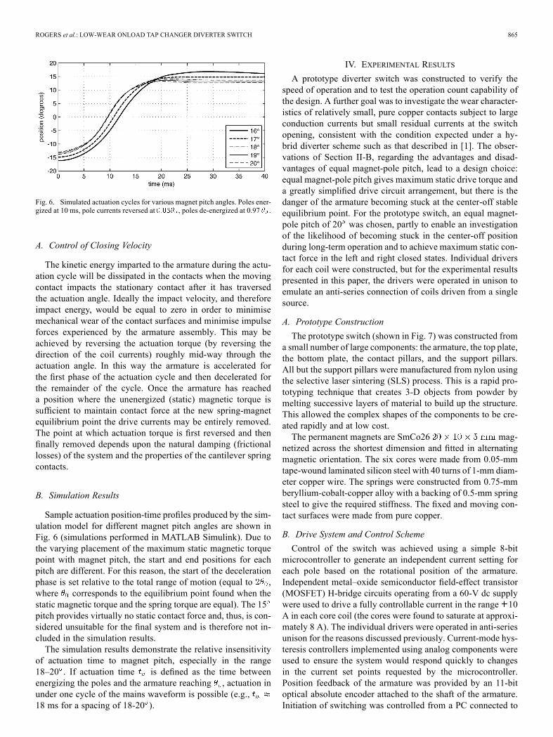
Fig. 6. Simulated actuation cycles for various magnet pitch angles. Poles ener-gized at 10 ms, pole currents reversed at , poles de-energized at 0.97 .
A. Control of Closing Velocity
The kinetic energy imparted to the armature during the actu-ation cycle will be dissipated in the contacts when the movingcontact impacts the stationary contact after it has traversedthe actuation angle. Ideally the impact velocity, and thereforeimpact energy, would be equal to zero in order to minimisemechanical wear of the contact surfaces and minimise impulseforces experienced by the armature assembly. This may beachieved by reversing the actuation torque (by reversing thedirection of the coil currents) roughly mid-way through theactuation angle. In this way the armature is accelerated forthe first phase of the actuation cycle and then decelerated forthe remainder of the cycle. Once the armature has reacheda position where the unenergized (static) magnetic torque issufficient to maintain contact force at the new spring-magnetequilibrium point the drive currents may be entirely removed.The point at which actuation torque is first reversed and thenfinally removed depends upon the natural damping (frictionallosses) of the system and the properties of the cantilever springcontacts.
B. Simulation Results
Sample actuation position-time profiles produced by the sim-ulation model for different magnet pitch angles are shown inFig. 6 (simulations performed in MATLAB Simulink). Due tothe varying placement of the maximum static magnetic torquepoint with magnet pitch, the start and end positions for eachpitch are different. For this reason, the start of the decelerationphase is set relative to the total range of motion (equal to ,where corresponds to the equilibrium point found when thestatic magnetic torque and the spring torque are equal). The 15pitch provides virtually no static contact force and, thus, is con-sidered unsuitable for the final system and is therefore not in-cluded in the simulation results.The simulation results demonstrate the relative insensitivity
of actuation time to magnet pitch, especially in the range18–20 . If actuation time is defined as the time betweenenergizing the poles and the armature reaching , actuation inunder one cycle of the mains waveform is possible (e.g.,18 ms for a spacing of 18-20 ).
IV. EXPERIMENTAL RESULTS
A prototype diverter switch was constructed to verify thespeed of operation and to test the operation count capability ofthe design. A further goal was to investigate the wear character-istics of relatively small, pure copper contacts subject to largeconduction currents but small residual currents at the switchopening, consistent with the condition expected under a hy-brid diverter scheme such as that described in [1]. The obser-vations of Section II-B, regarding the advantages and disad-vantages of equal magnet-pole pitch, lead to a design choice:equal magnet-pole pitch gives maximum static drive torque anda greatly simplified drive circuit arrangement, but there is thedanger of the armature becoming stuck at the center-off stableequilibrium point. For the prototype switch, an equal magnet-pole pitch of 20 was chosen, partly to enable an investigationof the likelihood of becoming stuck in the center-off positionduring long-term operation and to achieve maximum static con-tact force in the left and right closed states. Individual driversfor each coil were constructed, but for the experimental resultspresented in this paper, the drivers were operated in unison toemulate an anti-series connection of coils driven from a singlesource.
A. Prototype Construction
The prototype switch (shown in Fig. 7) was constructed froma small number of large components: the armature, the top plate,the bottom plate, the contact pillars, and the support pillars.All but the support pillars were manufactured from nylon usingthe selective laser sintering (SLS) process. This is a rapid pro-totyping technique that creates 3-D objects from powder bymelting successive layers of material to build up the structure.This allowed the complex shapes of the components to be cre-ated rapidly and at low cost.The permanent magnets are SmCo26 mag-
netized across the shortest dimension and fitted in alternatingmagnetic orientation. The six cores were made from 0.05-mmtape-wound laminated silicon steel with 40 turns of 1-mm diam-eter copper wire. The springs were constructed from 0.75-mmberyllium-cobalt-copper alloy with a backing of 0.5-mm springsteel to give the required stiffness. The fixed and moving con-tact surfaces were made from pure copper.
B. Drive System and Control Scheme
Control of the switch was achieved using a simple 8-bitmicrocontroller to generate an independent current setting foreach pole based on the rotational position of the armature.Independent metal–oxide semiconductor field-effect transistor(MOSFET) H-bridge circuits operating from a 60-V dc supplywere used to drive a fully controllable current in the range 10A in each core coil (the cores were found to saturate at approxi-mately 8 A). The individual drivers were operated in anti-seriesunison for the reasons discussed previously. Current-mode hys-teresis controllers implemented using analog components wereused to ensure the system would respond quickly to changesin the current set points requested by the microcontroller.Position feedback of the armature was provided by an 11-bitoptical absolute encoder attached to the shaft of the armature.Initiation of switching was controlled from a PC connected to
866 IEEE TRANSACTIONS ON POWER DELIVERY, VOL. 29, NO. 2, APRIL 2014
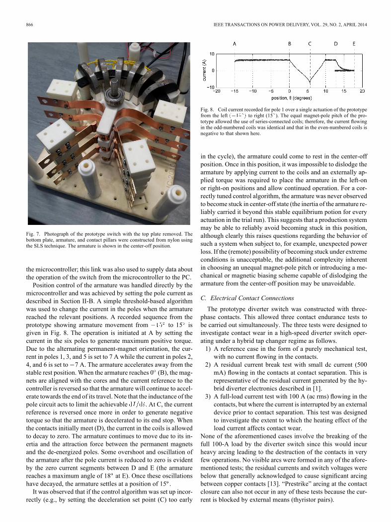
Fig. 7. Photograph of the prototype switch with the top plate removed. Thebottom plate, armature, and contact pillars were constructed from nylon usingthe SLS technique. The armature is shown in the center-off position.
the microcontroller; this link was also used to supply data aboutthe operation of the switch from the microcontroller to the PC.Position control of the armature was handled directly by the
microcontroller and was achieved by setting the pole current asdescribed in Section II-B. A simple threshold-based algorithmwas used to change the current in the poles when the armaturereached the relevant positions. A recorded sequence from theprototype showing armature movement from to 15 isgiven in Fig. 8. The operation is initiated at A by setting thecurrent in the six poles to generate maximum positive torque.Due to the alternating permanent-magnet orientation, the cur-rent in poles 1, 3, and 5 is set to 7 A while the current in poles 2,4, and 6 is set to 7 A. The armature accelerates away from thestable rest position. When the armature reaches 0 (B), the mag-nets are aligned with the cores and the current reference to thecontroller is reversed so that the armature will continue to accel-erate towards the end of its travel. Note that the inductance of thepole circuit acts to limit the achievable . At C, the currentreference is reversed once more in order to generate negativetorque so that the armature is decelerated to its end stop. Whenthe contacts initially meet (D), the current in the coils is allowedto decay to zero. The armature continues to move due to its in-ertia and the attraction force between the permanent magnetsand the de-energized poles. Some overshoot and oscillation ofthe armature after the pole current is reduced to zero is evidentby the zero current segments between D and E (the armaturereaches a maximum angle of 18 at E). Once these oscillationshave decayed, the armature settles at a position of 15 .It was observed that if the control algorithm was set up incor-
rectly (e.g., by setting the deceleration set point (C) too early
Fig. 8. Coil current recorded for pole 1 over a single actuation of the prototypefrom the left to right (15 ). The equal magnet-pole pitch of the pro-totype allowed the use of series-connected coils; therefore, the current flowingin the odd-numbered coils was identical and that in the even-numbered coils isnegative to that shown here.
in the cycle), the armature could come to rest in the center-offposition. Once in this position, it was impossible to dislodge thearmature by applying current to the coils and an externally ap-plied torque was required to place the armature in the left-onor right-on positions and allow continued operation. For a cor-rectly tuned control algorithm, the armature was never observedto become stuck in center-off state (the inertia of the armature re-liably carried it beyond this stable equilibrium potion for everyactuation in the trial run). This suggests that a production systemmay be able to reliably avoid becoming stuck in this position,although clearly this raises questions regarding the behavior ofsuch a system when subject to, for example, unexpected powerloss. If the (remote) possibility of becoming stuck under extremeconditions is unacceptable, the additional complexity inherentin choosing an unequal magnet-pole pitch or introducing a me-chanical or magnetic biasing scheme capable of dislodging thearmature from the center-off position may be unavoidable.
C. Electrical Contact Connections
The prototype diverter switch was constructed with three-phase contacts. This allowed three contact endurance tests tobe carried out simultaneously. The three tests were designed toinvestigate contact wear in a high-speed diverter switch oper-ating under a hybrid tap changer regime as follows.1) A reference case in the form of a purely mechanical test,with no current flowing in the contacts.
2) A residual current break test with small dc current (500mA) flowing in the contacts at contact separation. This isrepresentative of the residual current generated by the hy-brid diverter electronics described in [1].
3) A full-load current test with 100 A (ac rms) flowing in thecontacts, but where the current is interrupted by an externaldevice prior to contact separation. This test was designedto investigate the extent to which the heating effect of theload current affects contact wear.
None of the aforementioned cases involve the breaking of thefull 100-A load by the diverter switch since this would incurheavy arcing leading to the destruction of the contacts in veryfew operations. No visible arcs were formed in any of the afore-mentioned tests; the residual currents and switch voltages werebelow that generally acknowledged to cause significant arcingbetween copper contacts [13]. “Prestrike” arcing at the contactclosure can also not occur in any of these tests because the cur-rent is blocked by external means (thyristor pairs).

ROGERS et al.: LOW-WEAR ONLOAD TAP CHANGER DIVERTER SWITCH 867
Fig. 9. Photographs of contacts after operations. (a) Unused contacts. (b) Contacts with purely mechanical wear. (c) Contacts subject to 500 mA residual dccurrent. (d) Contacts subject to 100-A ac rms load current.
Fig. 10. Comparison of the (a) recorded and (b) simulated results for the switchshowing aging of the switch for the zeroth, five-hundred thousandth, and onemillionth operations. The Young’s modulus of the spring material and the co-efficient of friction were adjusted in the simulation to match the operation ofthe switch as it wore. (a) Results recorded from the prototype diverter switch.(b) Simulation results for the diverter switch using the coefficients given inTable II.
D. Endurance Testing
The prototype switch was operated once every 200 ms foroperations. Fig. 10 compares the data recorded for the ze-
roth, five-hundred thousandth, and millionth operations to sim-ulation results based on the model given in Section III using theparameters given in Table II. The figure shows that the varia-tion in the operation of the prototype can be replicated in thesimulation by varying the operating parameters, especially thespring constant (9) and the contact friction (6), in which case,the simulated results agree well with the actual operation of the
TABLE IISIMULATION COEFFICIENTS
Fig. 11. Density plot compiled from operations of the diverter switchshowing left to right actuations only.
prototype switch. The simulations suggest that the spring mate-rial became less stiff over time, possibly due to fatigue (evidentin the slower movement), and that contact friction increased,likely due to roughening of the contact surfaces (evident in theincreased damping).Fig. 11 is a density plot compiled from data for every opera-
tion recorded during the trial run. This illustrates how the me-chanical performance of the switch varied over the course of therun. The switch consistently operated in under 20 ms (start ofmotion to opposing contact) although there is some variation inthe actuation profile, likely due to weakening of the cantileversprings coupled with an increase in contact friction as indicatedby the simulation model.
E. Switch Longevity
After the completion of operations, the switch was dis-assembled to allow examination of the individual components.The nylon parts, including the armature, showed no significantwear. This is a testament to the robustness of the SLS processand the low-energy contact closure scheme that minimized im-pact impulse forces applied to the system. Notably, the beryl-lium copper spring layers had begun to show some signs offatigue in the form of microcracks appearing on the outside(convex) surface. This lends weight to the hypothesis that the

868 IEEE TRANSACTIONS ON POWER DELIVERY, VOL. 29, NO. 2, APRIL 2014
reduction in speed of the switch over the trial run was due pri-marily to reduced spring stiffness leading to reduced initial ac-celerating torque.Photographs of the contact surfaces are shown in Fig. 9. The
photographs demonstrate an acceptable level of wear, with nosurface indented by more than 0.5 mm. The differences betweeneach set of contacts are fairly small, with only subtly differentwear patterns in the contacts subjected to current compared tothe no-current contacts. It appears as though the wear rate forboth current-carrying contacts is roughly twice that for the me-chanical contacts. This is in broad agreement with the wearpatterns demonstrated in [1], although it should be noted thatthe contact material and size of the contacts are very differentin these two cases. It is known that sliding contacts of purecopper have relatively poor wear characteristics when comparedto harder metals or to noble metals [14]. However, contact resis-tance and contact temperature are low for a given contact forcedue to the high ductility and high electrical and thermal conduc-tivities of copper. Coupled with the fact that copper contacts arelow cost and that Fig. 9 does not indicate prohibitively high wearrates, it is possible to conclude that copper contacts may be anattractive option for use in a production version of the design.
V. CONCLUSION
Hybrid OLTC systems are one way of tackling distributionnetwork voltage-control problems that will become con-straining as EV charging and distributed PV generation becomemore common. The ability of hybrid OLTC systems to almostcompletely eliminate electrical arcing during operation allowsthe mechanical switching system to be drastically reduced insize and mass. This is because the electrical contacts may bedesigned only to carry the load current, rather than to toleratearc erosion as in classic OLTC systems. It was hypothesized thatthis would allow the development of very compact, high-speedair-insulated switching systems capable of operating in undera cycle of the mains waveform. In order to investigate theachievable speed and operation count capability of such asystem, a prototype switch was designed, modelled, con-structed, and tested. A central design decision was to employa permanent-magnet actuator to provide high torque with lowarmature inertia while also generating large static contact forceswhen unenergized. The results of testing demonstrate goodagreement between the model and practice while providinga clear indication of the degradation mechanisms. Crucially,this first prototype delivered more than one million switchingoperations while also demonstrating very low contact wearrates under realistic electrical contact conditions.
REFERENCES
[1] D. Rogers and T. Green, “An active-shunt diverter for onload tapchangers,” IEEE Trans. Power Del. , vol. 28, no. 2, pp. 649–657, Apr.2013.
[2] R. Tonkoski, D. Turcotte, and T. H. M. El-Fouly, “Impact of high PVpenetration on voltage profiles in residential neighborhoods,” IEEETrans. Sustain. Energy, vol. 3, no. 3, pp. 518–527, Jul. 2012.
[3] M. S. Kamarudin, M. Albano, P. Coventry, N. Harid, and A. Haddad,“A survey on the potential of CF3I gas as an alternative for SF6 in highvoltage applications,” in Proc. 45th Int. Univ. Power Eng. Conf., 2010,pp. 1–5.
[4] Reinhausen Group, On-load tap-changers for power transformers,A Technical Digest PB 252/04 Oct. 2010. [Online]. Available:http://www.reinhausen.com/
[5] H. Jiang, R. Shuttleworth, B. A. Zahawi, X. Tian, and A. Power, “Fastresponse GTO assisted novel tap changer,” IEEE Trans. Power Del.,vol. 16, no. 1, pp. 111–115, Jan. 2001.
[6] Reinhausen Group, On-load tap-changer vacutap vv, Technical data TD203/04. Aug. 2010. [Online]. Available: http://www.reinhausen.com/
[7] P. M. Huang and M. C. Tsai, “Design of a magnet-switching actuatorwith high efficiency and auto-locking function,” IEEE Trans. Magn.,vol. 48, no. 11, pp. 4622–4625, Nov. 2012.
[8] D. J. Rogers, “Hybrid and thin power electronics for electrical powernetworks,” Ph.D. dissertation, Dept. Elect. Comput. Eng., ImperialCollege London, London, U.K., Feb. 2011.
[9] K. B. Baltzis, “The FEMM package: A simple, fast, and accurate opensource electromagnetic tool in science and engineering,” J. Eng. Sci.Technol. Rev., vol. 1, no. 1, pp. 83–89, 2008.
[10] R. Holm, Electric Contacts, 4th ed. Berlin, Germany: Springer-Verlag, 1967.
[11] S. Timsit, “Electrical contact resistance: Properties of stationary inter-faces,” in Proc. 44th IEEE Holm Conf. Elect. Contacts, Oct. 1998, pp.1–19.
[12] B. Goodwine, Engineering Differential Equations: Theory and Appli-cations. New York: Springer, 2010.
[13] P. G. Slade, Electrical Contacts: Principles and Applications. NewYork: Taylor & Francis, 1999, pp. 463–464.
[14] M. Antler, “Sliding wear of metallic contacts,” IEEE Trans. Compon.,Hybrids, Manuf. Technol., vol. TCHMT–4, no. 1, pp. 15–29, Mar.1981.
Daniel J. Rogers (M’11) received the M.Eng. andPh.D. degrees in electrical and electronic engineeringfrom Imperial College London, London, U.K., in2007 and 2011, respectively.Currently, he is a Lecturer in the Institute of
Energy, Cardiff University, Cardiff, U.K. He con-ducts research in collaboration with industry and isinvolved with the development of high-performancepower electronic systems for a variety of companies.He is a co-investigator on the multi-institutionEPSRC Energy Storage for Low Carbon Grids
project. His interests include the use of medium- and large-scale power-elec-tronic systems to create flexible electrical networks capable of taking advantageof a diverse range of generation technologies, and the subsequent control chal-lenges this produces.
Tim C. Green (M’89–SM’02) received the B.Sc.(Hons.) degree in electrical engineering from Impe-rial College, London, U.K., in 1986 and the Ph.D.degree in electrical engineering from Heriot-WattUniversity, Edinburgh, U.K., in 1990.Currently, he is a Chartered Engineer in the U.K.
He was a Lecturer at Heriot Watt University until1994 and is currently a Professor of Electrical PowerEngineering at Imperial College London and DeputyHead of the Electrical and Electronic EngineeringDepartment. His research interest is in formulating
the future form the electricity network to support low-carbon futures. Aparticular theme is how the flexibility of power electronics and control can beused to accommodate new-generation patterns and new forms of load, such asEV charging, as part of the emerging smart grid. He has particular interests inoffshore dc networks and the management of low-voltage networks.Prof. Green leads the HubNet consortium of eight U.K. universities coordi-
nating research in low-carbon energy networks and is the Network Championfor the Research Councils U.K.

ROGERS et al.: LOW-WEAR ONLOAD TAP CHANGER DIVERTER SWITCH 869
RichardW. Silversides (M’13) received the M.Eng.degree in engineering science from Oxford Univer-sity, Oxford, U.K., in 1992 and the M.Sc. degree inmechatronics (Hons.) and the Ph.D. degree in engi-neering from King’s College London, London, U.K.,in 2002 and 2007, respectively.He then went to work for the National Grid Com-
pany plc, the Transmission Network Owner and Op-erator for England and Wales, with the Engineeringand Technology Group, Leatherhead, U.K., where heachieved Chartered Engineer status. His main inter-
ests were supervisory control and data acquisition and the integration of substa-tion control, monitoring, and protection systems. Currently, he is a Research As-sociate at Imperial College, London, in the Control and Power Research Group,where he runs the Smart Energy Lab. His research interests are ICT for powernetworks and power electronics for distribution systems.