9 hvp high voltage catalog full version 1 30
DESCRIPTION
9-HVP-High-Voltage-Catalog-Full-Version-1-30TRANSCRIPT


2
INTRODUCTIONTELE-FONIKA Kable S.A. is the biggest cable producer
in Central and Eastern Europe. In terms of sales, it is
Europe’s fourth biggest cable manufacturer and is
noted as one of the world’s largest suppliers of high
voltage cables and systems.
The company was founded in 1992 and is presently one
of the biggest private enterprises operating in Poland.
The present position of the company is the result of
dynamic development supported by the realization
of investment projects in 1994-2003, including the
purchase of Krakowska Fabryka Kabli SA (1998) and
Elektrim Kable SA (2002).
Tele-Fonika Kable S.A. offers design, delivery, execu-
tion and tests of complete High Voltage Cable Systems.
Our high position has been built thanks to continuous
research and development as well as state-of-the-art
production machinery and top quality materials. We
co-operate with the best suppliers of HV cable ac-
cessories so that we can assure operational reliability
of power supply. Our product, deliveries and solidity
of installation present the highest quality standards
that fulfil the most demanding needs of our custom-
ers. Our systems have a strong support from our en-
gineering staff from the High Voltage Cable System
Department.
A Research and development program in the range of
preparation and testing of cable systems was initiated in


4
1988, when the fi rst CCV line of Nokia-Mailleff er was in-
stalled in our Bydgoszcz factory. After achieving positive
results from the testing of the system according to IEC
60840 at Power Institute in Warsaw, the fi rst line of 110
kV was built for Power Plant in Warsaw Area in 1992.
In the next stage, the production range was extended
to include EHV cables up to 400 kV and conductor
cross-section up to 2000 mm2.
The last investment was realized in 2003, when the
completely new MV & HV Department was built in
Bydgoszcz factory. It was equipped with state-of-
the-art XLPE insulation line as well as screening and
jacketing lines.
QUALITYMANAGEMENTSYSTEMTELE-FONIKA Kable S.A. has established, documented
and implemented the Quality Management System
according to the ISO 9001:2000 standard as well as
the Environmental Protection System according to
the ISO 14001:2004 standard.
The management system covers the entire organisa-
tional structure of the Company, supporting the divi-
sion of tasks, responsibilities and competences, and
the breakdown of processes and resources, making
it possible to maintain effective quality and environ-
mental management.
Customer requirements are studied and care is taken
to ensure that they are fulfilled through the provision
of products that are in accordance with previously
agreed specifications, of the highest quality, safe to
use, reliable and delivered on time.
Operational control in the integrated management
system allows the Company to function in an envi-
ronmentally safe way. It also ensures realisation of the
environmental policy and the execution of accepted
objectives and tasks.

5

6
We constantly strive to improve our activities and
processes having in mind the highest quality of our
products, customer satisfaction, professionalism and
environmentally friendly operations.
PRODUCTIONPROCESS
THE CONDUCTOR
Round, stranded copper or aluminium conductor de-
signed to achieve specific cross-section, resistance
and outer diameter, optionally with longitudinal wa-
ter barrier.
Conductors with cross-section >1000 mm2 are pro-
duced as segmented conductors.
INSULATING OF PHASE CONDUCTOR
In the insulation process polyethylene is delivered to
extruders from the specially prepared clean room, in
which air circulation takes place by means of special
filters that ensure the level of air cleanliness. The trans-
portation of semi-conductive and insulating materi-
als is by means of separated tracks. Additionally the
insulating polyethylene dosing system is completed
by a device that removes dust, non-dimensional gran-
ules, etc.
MATERIAL HANDLING SYSTEM
System of feeding the materials to clean the PE insulat-
ing components to production of high-voltage cables.
The cleaning of XLPE granules by means of an air sepa-
rator unit, consisting of magnetic separator, ionizer and
cascade-air sorter. A magnetic separator shows a strong
magnetic fi eld; in addition all metallic impurities, when
they are present in plastic, stick very strongly to it.
During the pneumatic transport granules are loaded
electrostatically so that no dust adheres to their sur-
face. Ionizer effectively reduces accumulated load so
that dust cannot be blown. The removing of dust is
additionally aided mechanically by repeated padding
granules in the cascade-air sorter.
Triple extrusion process of insulation material (semi-
conductive inner screen, insulation, semi-conductive
outer screen) over a phase conductor is realized in
one operation with continuous on-line control of the
important parameters of each layer as thickness, cen-
tricity and ovality.

7
EXTRA HEAT TREATMENT
To avoid “the leakage of insulation” effect, that may
appear during the production of high-voltage cables
with high diameter coefficient (outer diameter of in-
sulation/ diameter of phase conductor) and to ensure
the ovality and centricity of cables, the EHT system is
used on CCV lines. The solution relies on injection of
inert gas directly behind the crosshead that extrudes
three layers of insulation. It causes the reduction of
stickiness of the outer layer of insulation and con-
sequently reduces “the leakage of insulation”. Cross-
linking and cooling the polyethylene takes place in
a nitrogen atmosphere.
RELAXATION SYSTEM DURING ROL PRODUCTION
Specific volumes of plastics are reduced by a decrease
in temperature. This dependence on temperature
causes uneven mechanical tensions inside insulation
of cable. During the cooling process of the insulating
system of cables there are tensions resulting from the
uneven crystallization of material. A direct relaxation
method is used on lines to minimize mechanical ten-
sions in XLPE insulation and to reduce its longitudinal
return shrinkage. The system is based on an additional
heating zone in the central cooling section of the con-
tinuous vulcanization line.
DEGASSING OF CABLE INSULATION FROM THE DE-
RIVATIVES OF CROSS-LINKING PROCESS
To ensure the controlled conditions of degassing of
high-voltage cable insulation, the heating chambers
are used. The result of cross-linking process is de-
composition of cross-linking factor (peroxide) that
generates by-products like aceto-phenone, meth-
ane, methyl styrene, etc. In thermally controlled
conditions the insulated conductors are subjected
to slow degassing process. The time of keeping in-
sulated conductors in degassing chambers is a func-
tion of temperature and thickness of insulation. The
degree of degassing of insulation is controlled on
measurement area.
SCREENING
Applying on insulated conductor:
blockade in water-blocked cables)
ade in water-blocked cables)
EXTRUSION OF OUTER SHEATH
Extrusion – on cable core – outer PVC, PE or LSOH
sheath. In case of cables sealed radially – additionally
Al/ Cu tape covered with copolymer is applied longi-
tudinally on a cable core. As a result of the extrusion
of the sheath there is a durable bonding of tape with
the outer sheath
HV LABORATORY
To ensure the possibility of testing HV and EHV cables
and cable accessories, a HV laboratory was built and
equipped with state-of-the-art devices. The range of
equipment in our HV laboratory enable us to perform
the routine as well as type tests up to 400kV.
QUALITY EVIDENCE
Every complete system is type tested under super-
vision of a representative of an independent labo-
ratory and in cases of positive results, it receives
confirmation of technical properties and can be
used in power networks. Those tests ensure full
compatibility of cables and accessories and guar-
antee high quality and a durability in operation
without breakdown.

8
TYPE OF CABLESXRUHAKXS, XRUHKXS - NA2XS(FL)2Y, N2XS(FL)2Y, NRUHAKXS,
NRUHKXS - NA2XS(FL)H, N2XS(FL)H
Legend to the figure 1.
1 – Aluminium or copper conductor.
2 – Semi-conductive screen extruded on the phase conductor.
3 – XLPE insulation.
4 – Semi-conductive screen extruded on insulation.
5 – Wrapping of semi-conductive water swelling tape
6 – Metallic screen.
7 – Wrapping of semi-conductive water swelling tape
8 – Longitudinally applied aluminium tape coated with PE copolymer.
9 – MDPE outer sheath.
For the special application Tele-Fonika Kable S.A. offered single-core a cable type
YHAKXS, YHKXS - NA2XSY, N2XSY - XHAKXS, XHKXS - NA2XS2Y,
N2XS2Y, NHAKXS, NHKXS - NA2XSH, N2XSH
Legend to the figure 2.
1 – Aluminium or copper conductor.
2 – Semi-conductive screen extruded on the phase conductor.
3 – XLPE insulation.
4 – Semi-conductive screen extruded on insulation.
5 – Semi-conductive tape wrap, non swelling under action of water.
6 – Metallic screen.
7 – Wrapping of polyester tape.
8 – Outer sheath: PVC, MDPE, LSF
1
1
2
2
3
3
4
4
5
5
6
6
7
7
8
8
9

9
XUHAKXS, XUHKXS - NA2XS(F)2Y, N2XS(F)2Y, NUHAKXS, NUHKXS - NA2XS(F)H, N2XS(F)H
Legend to the figure 3.1 – Aluminium or copper conductor.2 – Semi-conductive screen extruded on the phase conductor.3 – XLPE insulation.4 – Semi-conductive screen extruded on insulation.5 – Wrapping of semi-conductive water swelling tape6 – Metallic screen.7 – Wrapping of non conductive water swelling tape8 – Outer sheath: MDPE, LSF
CABLE SELECTIONHigh-voltage cables are manufactured on the basis of customers’ specifications or factory standard.
Constructing of cables is mainly on the basis of IEC standards.
IEC 60287 – Electric cables - Calculation of the current rating. Current rating equations (100 % load factor)
and calculation of losses
IEC 60853 – Calculation of the cyclic and emergency current rating of cables
IEC 61443 – Short-circuit temperature limits of electric cables with rated voltages above 30 kV (Um = 36 kV)
IEC 60228 – Conductors of insulated cables
The aim of increase of efficiency of constructional works was prepared by computer program that enables
not only calculations but also simulation of operating conditions of cable system.
CALCULATION BASIS:IN GROUND – temperature 20OC , laying depth 1,0 m, soil thermal resistivity K = 1,0 Km/W, phase distance at
flat formation = 70 mm + cable diameter
For cables installed in separate pipes the ampacity is reduced to 90% of values presented in tables on next pages.
IN AIR – temperature 30OC
LAYING CONDITION:
Minimum laying temperature: minus 20OC
Minimum bending radius: values in mm according to tables on next pages
Maximum pulling force by means of the conductor or a basket over an outer jacket: values in kN according to
tables above Minimum inner diameter of pipe: min. 1.5 x D (mm) , where D = outer cable diameter in mm.
The constructions detailed in this catalogue cover the most popular designs but please note that
Tele-Fonika Kable has the capability to manufacture HV cables according to other standards as well as
specific customer’s requirements.
1 2 3 4 5 6 7 8

10
Cross-section of conductor
Diameter of conductor
Insulation Copper screen
Outer diameter of cable
Weight of cable
Max. pulling force
Min. bending radiusAverage thick-
nessDiameter over
insulationCross-section
Diameter over screen
mm2 mm mm2 mm kg / km kN m
1 x 120 RM 12.9 + 0.25 13.0 41.5 35 48.0 57.0 3370 6.0 1.27
1 x 150 RM 14.5 + 0.30 12.0 41.2 35 47.6 56.7 3550 7.5 1.26
1 x 185 RM 16.0 + 0.30 12.0 42.7 35 49.1 58.2 3960 9.25 1.30
1 x 240 RM 18.5 + 0.30 11.0 43.2 35 49.6 58.7 4420 12 1.31
1 x 300 RM 20.5 + 0.30 11.0 45.6 35 52.4 61.7 5160 15 1.38
1 x 400 RM 23.5 + 0.30 11.0 48.6 35 55.4 64.9 6130 20 1.46
1 x 500 RM 26.5 + 0.40 10.0 49.7 35 56.5 66.2 7110 25 1.48
1 x 630 RM 30.3 + 0.40 10.0 55.0 35 62.2 72.3 8760 31.5 1.61
1 x 800 RM 34.6 + 0.50 10.0 59.4 35 66.6 76.9 10540 40 1.72
1 x 1000 RM 37.6 + 0.50 10.0 62.4 50 69.6 80.1 12660 50 1.81
1 x 1200 RMS 43.6 + 0.80 10.0 69.2 50 76.6 87.7 15000 60 1.99
1 x 1400 RMS 46.6 + 1.0 10.0 72.8 50 80.2 91.5 17100 70 2.08
1 x 1600 RMS 50.0 + 1.0 10.0 76.8 50 84.6 96.3 19290 80 2.19
1 x 1800 RMS 53.3 + 1.0 10.0 80.1 50 87.9 99.8 21310 90 2.27
1 x 2000 RMS 56.3 + 1.2 10.0 83.3 50 91.1 103.2 23380 100 2.35
HIGH VOLTAGEXLPE CABLES36/60 69(72.5)kV
COPPER CONDUCTOR
acc. DIN VDE 0276-632

11
Cross-section of conductor
Conductor resistance Copper screen resistance Field strengthat conductor
screen / insulation
Max. short circuit current
Capacitance
InductanceoOo /1
o o o /2
o o o /3
Ampacity
DC20 OC AC90 OC DC20 OC AC80 OC ConductorCopper screen
In ground In air
SPB, CB /4 o o o / oOo
Both-ends /4 o o o / oOo
mm2 Ω / km kV / mm kA / 1 sec µF / km mH / km A
1 x 120 RM 0.153 0.1956 0.531 0.656 4.71 / 1.70 17.16 7.1 0.13 0.480.670.69380 / 365 483 / 420370 / 365 462 / 420
1 x 150 RM 0.124 0.1587 0.531 0.656 4.77 / 1.92 21.45 7.1 0.14 0.460.640.66435 / 410 551 / 478410 / 410 520 / 478
1 x 185 RM 0.0991 0.1273 0.531 0.656 4.63 / 1.96 26.45 7.1 0.15 0.440.630.65490 / 465 630 / 546455 / 460 583 / 546
1 x 240 RM 0.0754 0.0973 0.531 0.656 4.72 / 2.25 34.32 7.1 0.17 0.420.600.62570 / 540 745 / 645515 / 530 672 / 640
1 x 300 RM 0.0601 0.0782 0.531 0.656 4.57 / 2.31 42.9 7.1 0.19 0.410.590.60645 / 610 861 / 740570 / 600 756 / 730
1 x 400 RM 0.047 0.062 0.531 0.656 3.43 / 2.37 57.2 7.1 0.20 0.390.570.58735 / 690 1003 / 856630 / 675 856 / 840
1 x 500 RM 0.0366 0.0495 0.531 0.656 4.62 / 2.71 71.5 7.1 0.24 0.370.550.56835 / 785 1160 / 992695 / 760 955 / 961
1 x 630 RM 0.0283 0.0397 0.531 0.656 4.46 / 2.79 90.09 7.1 0.27 0.360.540.54950 / 885 1349 / 1139760 / 845 1066 / 1097
1 x 800 RM 0.0221 0.0327 0.531 0.656 4.36 / 2.85 114.4 7.1 0.30 0.350.530.521070 / 990 1544 / 1291
820 / 930 1176 / 1234
1 x 1000 RM 0.0176 0.0278 0.372 0.460 4.30 / 2.88 143 7.1 0.32 0.340.520.511180 / 1080 1743 / 1444
848 / 980 1244 / 1326
1 x 1200 RMS 0.0151 0.0207 0.372 0.460 4.19 / 2.94 171.6 10.15 0.36 0.330.510.491365 / 1280 2063 / 1754917 / 1111 1385 / 1548
1 x 1400 RMS 0.0129 0.018 0.372 0.460 4.15 / 2.97 200.2 10.15 0.38 0.320.510.481475 / 1380 2268 / 1916955 / 1174 1467 / 1670
1 x 1600 RMS 0.0113 0.0162 0.372 0.460 4.1 / 3.0 228.8 10.15 0.41 0.320.500.471570 / 1465 2457 / 2058985 / 1227 1538 / 1772
1 x 1800 RMS 0.0101 0.0149 0.372 0.460 4.07 / 3.02 257.4 10.15 0.43 0.310.500.461650 / 1530 2604 / 21741004 / 1259 1571 / 1834
1 x 2000 RMS 0.009 0.0137 0.372 0.460 4.04 / 3.04 286 10.15 0.45 0.310.490.461730 / 1600 2751 / 22841536 / 1291 1608 / 1900
ELECTRICAL PARAMETERS
RM – round multiwire conductor
RMS – round multiwire segmented conductor (Milliken construction)
/1 – trefoil formation
/2 – phase distance at flat formation = 2 x cable diameter
/3 – phase distance at flat formation = 70 mm + cable diameter
/4 – SPB – Single Point Bonding; CB – Cross-bonding; Both-ends – Both-ends Bonding

12
Cross-section of conductor
Diameter of conductor
Insulation Copper screen
Outer diameter of cable
Weight of cable
Max. pulling force
Min. bending radiusAverage thick-
nessDiameter over
insulationCross-section
Diameter over screen
mm2 mm mm2 mm kg / km kN m
1 x 120 RM 12.5 + 0.20 13.0 41.1 35 47.5 56.6 2620 3.6 1.26
1 x 150 RM 14.2 + 0.20 12.0 40.8 35 47.2 56.3 2640 4.5 1.25
1 x 185 RM 15.8 + 0.20 12.0 42.4 35 48.8 57.9 2820 5.55 1.29
1 x 240 RM 17.8 + 0.10 11.0 42.3 35 48.7 57.8 2920 7.2 1.29
1 x 300 RM 20.0 + 0.30 11.0 45.1 35 51.9 61.2 3290 9.0 1.37
1 x 400 RM 22.9 + 0.30 11.0 48.0 35 54.8 64.3 3700 12.0 1.44
1 x 500 RM 25.7 + 0.40 10.0 48.9 35 55.7 65.4 3980 15.0 1.46
1 x 630 RM 29.3 + 0.50 10.0 54.1 35 61.3 71.2 4750 18.9 1.60
1 x 800 RM 33.0 + 0.50 10.0 57.8 35 65.0 75.3 5440 24.0 1.70
1 x 1000 RM 38.0 + 0.50 10.0 62.8 50 70.0 80.7 6470 30.0 1.82
1 x 1200 RM 41.0 + 0.60 10.0 65.9 50 73.3 84.2 7280 36.0 1.90
1 x 1200 RMS 43.6 + 0.80 10.0 69.2 50 76.6 87.7 7600 36.0 1.99
1 x 1400 RMS 46.6 + 1.0 10.0 72.8 50 80.2 91.5 8420 42.0 2.08
1 x 1600 RMS 50.0 + 1.0 10.0 76.8 50 84.6 96.3 9370 48.0 2.19
1 x 1800 RMS 53.3 + 1.0 10.0 80.1 50 87.3 99.8 10170 54.0 2.27
1 x 2000 RMS 55.4 + 1.2 10.0 82.4 50 90.2 102.3 10800 60.0 2.33
HIGH VOLTAGE XLPE CABLES36/60 69(72.5)kV
ALUMINIUM CONDUCTOR

13
ELECTRICAL PARAMETERS
RM – round multiwire conductor
RMS – round multiwire segmented conductor (Milliken construction)
/1 – trefoil formation
/2 – phase distance at flat formation = 2 x cable diameter
/3 – phase distance at flat formation = 70 mm + cable diameter
/4 – SPB – Single Point Bonding; CB – Cross-bonding; Both-ends – Both-ends Bonding
Cross-section of conductor
Conductor resistance Copper screen resistance Field strengthat conductor
screen / insulation
Max. short circuit current
Capacitance
InductanceoOo /1
o o o /2
o o o /3
Ampacity
DC20 OC AC90 OC DC20 OC AC80 OC ConductorCopper screen
In ground In air
SPB, CB /4 o o o / oOo
Both-ends /4 o o o / oOo
mm2 Ω / km kV / mm kA / 1 sec µF / km mH / km A
1 x 120 RM 0.253 0.3243 0.531 0.656 4.77 / 1.68 11.34 7.1 0.12 0.490.670.69300 / 285 373 / 326295 / 285 368 / 331
1 x 150 RM 0.206 0.2644 0.531 0.656 4.81 / 1.91 14.18 7.1 0.14 0.460.650.67335 / 320 431 / 373325 / 320 415 / 373
1 x 185 RM 0.164 0.2105 0.531 0.656 4.66 / 1.96 17.48 7.1 0.15 0.450.630.65380 / 360 494 / 425365 / 360 467 / 425
1 x 240 RM 0.125 0.1607 0.531 0.656 4.78 / 2.23 22.68 7.1 0.17 0.420.610.63445 / 420 583 / 504420 / 420 546 / 504
1 x 300 RM 0.100 0.1289 0.531 0.656 4.60 / 2.30 28.35 7.1 0.18 0.410.590.61500 / 475 672 / 578465 / 470 620 / 578
1 x 400 RM 0.0778 0.101 0.531 0.656 4.45 / 2.36 37.8 7.1 0.20 0.390.580.59575 / 545 782 / 677520 / 540 709 / 667
1 x 500 RM 0.0605 0.0794 0.531 0.656 4.65 / 2.69 47.25 7.1 0.23 0.370.560.56660 / 620 914 / 788585 / 610 803 / 772
1 x 630 RM 0.0469 0.0624 0.531 0.656 4.48 / 2.78 59.54 7.1 0.27 0.360.550.55755 / 710 1071 / 914
650 / 690 914 / 893
1 x 800 RM 0.0367 0.0501 0.531 0.656 4.39 / 2.83 75.6 7.1 0.29 0.350.540.53855 / 805 1239 / 1055710 / 775 1024 / 1024
1 x 1000 RM 0.0291 0.0412 0.372 0.460 4.29 / 2.88 94.5 10.15 0.32 0.340.520.51960 / 895 1418 / 1197767 / 846 1123 / 1143
1 x 1200 RM 0.0247 0.0362 0.372 0.460 4.24 / 2.91 113.4 10.15 0.34 0.330.510.501040 / 965 1565 / 1307807 / 906 1201 / 1237
1 x 1200 RMS 0.0247 0.0326 0.372 0.460 4.19 / 2.94 113.4 10.15 0.36 0.330.510.491040 / 965 1565 / 1307807 / 906 1201 / 1237
1 x 1400 RMS 0.0212 0.0282 0.372 0.460 4.15 / 2.97 132.3 10.15 0.38 0.320.510.481115 / 1030 1701 / 1412
842 / 951 1267 / 1319
1 x 1600 RMS 0.0186 0.025 0.372 0.460 4.10 / 3.0 151.2 10.15 0.41 0.320.500.471175 / 1080 1817 / 1496
867 / 985 1322 / 1390
1 x 1800 RMS 0.0165 0.0225 0.372 0.460 4.07 / 3.02 170.1 10.15 0.43 0.310.500.461230 / 1125 1922 / 1575890 / 1019 1372 / 1451
1 x 2000 RMS 0.0149 0.0206 0.372 0.460 4.05 / 3.04 189.0 10.15 0.44 0.310.490.461285 / 1170 2027 / 1654911 / 1054 1420 / 1513

14
HIGH VOLTAGE XLPE CABLES64/110 ÷ 115(123)kV
COPPER CONDUCTOR
Cross-section of conductor
Diameter of conductor
Insulation Copper screen
Outer diam-eter of cable
Weight of cable
Max. pulling force
Min. bending radiusAverage thick-
nessDiameter over
insulationCross-section
Diameter over screen
mm2 mm mm2 mm kg / km kN m
1 x 150 RM 14.5 + 0.30 18.0 54.8 95 62.5 72.5 5620 7.5 1.63
1 x 185 RM 16.0 + 0.30 17.0 53.7 95 61.4 71.2 5790 9.25 1.61
1 x 240 RM 18.5 + 0.30 16.0 54.2 95 61.9 71.9 6280 12 1.62
1 x 300 RM 20.5 + 0.30 15.0 54.0 95 61.7 71.7 6750 15 1.61
1 x 400 RM 23.5 + 0.30 15.0 57.0 95 64.7 74.9 7770 20 1.69
1 x 500 RM 26.5 + 0.40 15.0 60.1 95 67.8 78.2 8970 25 1.76
1 x 630 RM 30.3 + 0.40 15.0 65.0 95 72.7 83.3 10600 31.5 1.89
1 x 800 RM 34.6 + 0.50 15.0 69.4 95 77.1 88.1 12480 40 2.0
1 x 1000 RM 37.6 + 0.50 15.0 72.4 95 80.1 91.3 14500 50 2.07
1 x 1200 RMS 43.6 + 0.80 15.0 79.2 95 87.1 98.7 16930 60 2.25
1 x 1400 RMS 46.6 + 1.0 15.0 82.8 95 90.7 102.7 19120 70 2.34
1 x 1600 RMS 50.0 + 1.0 15.0 86.8 95 95.1 107.3 21360 80 2.45
1 x 1800 RMS 53.3 + 1.0 15.0 90.1 95 98.4 110.8 23420 90 2.53
1 x 2000 RMS 56.3 + 1.2 15.0 93.3 95 101.6 114.4 25590 100 2.61

15
Cross-section of conductor
Conductor resistance Copper screen resistance Field strengthat conductor
screen / insulation
Max. short circuit current
Capacitance
InductanceoOo /1
o o o /2
o o o /3
Ampacity
DC20 OC AC90 OC DC20 OC AC80 OC ConductorCopper screen
In ground In air
SPB, CB /4 o o o / oOo
Both-ends /4 o o o / oOo
mm2 Ω / km kV / mm kA / 1 sec µF / km mH / km A
1 x 150 RM 0.124 0.1586 0.215 0.266 6.39 / 2.10 21.45 19.29 0.11 0.510.690.69435 / 410 551 / 478406 / 406 515 / 473
1 x 185 RM 0.0991 0.1272 0.215 0.266 6.49 / 2.28 26.45 19.29 0.12 0.480.670.67490 / 465 630 / 546448 / 453 574 / 538
1 x 240 RM 0.0754 0.0972 0.215 0.266 6.44 / 2.54 34.32 19.29 0.14 0.460.640.64570 / 540 745 / 645505 / 519 659 / 628
1 x 300 RM 0.0601 0.078 0.215 0.266 6.54 / 2.83 42.9 19.29 0.15 0.440.620.62640 / 610 845 / 746535 / 580 719 / 719
1 x 400 RM 0.047 0.0618 0.215 0.266 6.30 / 2.92 57.2 19.29 0.17 0.420.600.60720 / 690 961 / 861595 / 650 814 / 824
1 x 500 RM 0.0366 0.0492 0.215 0.266 6.10 / 2.99 71.5 19.29 0.18 0.400.590.58825 / 785 1113 / 992650 / 730 903 / 940
1 x 630 RM 0.0283 0.0393 0.215 0.266 5.85 / 3.09 90.09 19.29 0.20 0.390.570.56940 / 890 1297 / 1139705 / 810 998 / 1061
1 x 800 RM 0.0221 0.0323 0.215 0.266 5.67 / 3.17 114.4 19.29 0.22 0.370.560.541055 / 995 1486 / 1297755 / 885 1092 / 1187
1 x 1000 RM 0.0176 0.0273 0.215 0.266 5.57 / 3.22 143 19.29 0.23 0.360.550.521165 / 1095 1670 / 1449
800 / 950 1181 / 1307
1 x 1200 RMS 0.0151 0.0205 0.215 0.266 5.39 / 3.31 171.6 19.29 0.26 0.350.540.501345 / 1280 1974 / 1733860 / 1055 1302 / 1496
1 x 1400 RMS 0.0129 0.0178 0.215 0.266 5.32 / 3.35 200.2 19.29 0.28 0.340.530.501455 / 1385 2168 / 1890890 / 1110 1365 / 1601
1 x 1600 RMS 0.0113 0.016 0.215 0.266 5.24 / 3.39 228.8 19.29 0.29 0.340.520.491550 / 1470 2347 / 2037920 / 1155 1423 / 1696
1 x 1800 RMS 0.0101 0.0147 0.215 0.266 5.18 / 3.42 257.4 19.29 0.31 0.330.520.481627 / 1537 2485 / 2145938 / 1187 1460 / 1762
1 x 2000 RMS 0.009 0.0135 0.215 0.266 5.14 / 3.45 286 19.29 0.32 0.330.510.471705 / 1605 2625 / 2252955 / 1220 1496 / 1827
ELECTRICAL PARAMETERS
RM – round multiwire conductor
RMS – round multiwire segmented conductor (Milliken construction)
/1 – trefoil formation
/2 – phase distance at flat formation = 2 x cable diameter
/3 – phase distance at flat formation = 70 mm + cable diameter
/4 – SPB – Single Point Bonding; CB – Cross-bonding; Both-ends – Both-ends Bonding

16
Cross-section of conductor
Diameter of conductor
Insulation Copper screen
Outer diameter of cable
Weight of cable
Max. pulling force
Min. bending radiusAverage thick-
nessDiameter over
insulationCross-section
Diameter over screen
mm2 mm mm2 mm kg / km kN m
1 x 150 RM 14.2 + 0.20 18.0 54.4 95 62.1 72.1 4700 4.5 1.62
1 x 185 RM 15.8 + 0.20 17.0 53.4 95 61.1 70.9 4650 5.55 1.60
1 x 240 RM 17.8 + 0.10 16.0 53.3 95 61.0 70.8 4740 7.2 1.60
1 x 300 RM 20.0 + 0.30 15.0 53.5 95 61.2 71.0 4850 9.0 1.60
1 x 400 RM 22.9 + 0.30 15.0 56.4 95 64.1 74.1 5290 12.0 1.67
1 x 500 RM 25.7 + 0.40 15.0 59.3 95 67.0 77.2 5810 15.0 1.75
1 x 630 RM 29.3 + 0.50 15.0 64.1 95 71.8 82.4 6590 18.9 1.87
1 x 800 RM 33.0 + 0.50 15.0 67.8 95 75.5 86.3 7320 24.0 1.96
1 x 1000 RM 38.0 + 0.50 15.0 72.8 95 80.5 91.7 8290 30.0 2.08
1 x 1200 RM 41.0 + 0.60 15.0 75.9 95 83.8 95.2 9150 36.0 2.17
1 x 1200 RMS 43.6 + 0.80 15.0 79.2 95 87.1 98.7 9530 36.0 2.25
1 x 1400 RMS 46.6 + 1.0 15.0 82.8 95 90.7 102.7 10440 42.0 2.34
1 x 1600 RMS 50.0 + 1.0 15.0 86.8 95 95.1 107.3 11440 48.0 2.45
1 x 1800 RMS 53.3 + 1.0 15.0 90.1 95 98.4 110.8 11290 54.0 2.53
1 x 2000 RMS 55.4 + 1.2 15.0 92.4 95 100.7 113.3 12950 60.0 2.59
HIGH VOLTAGE XLPE CABLES 64/110 115(123)kV
ALUMINIUM CONDUCTOR

17
Cross-section of conductor
Conductor resistance Copper screen resistance Field strengthat conductor
screen / insulation
Max. short circuit current
Capacitance
InductanceoOo /1
o o o /2
o o o /3
Ampacity
DC20 OC AC90 OC DC20 OC AC80 OC ConductorCopper screen
In ground In air
SPB, CB /4 o o o / oOo
Both-ends /4 o o o / oOo
mm2 Ω / km kV / mm kA / 1 sec µF / km mH / km A
1 x 150 RM 0.206 0.2644 0.215 0.266 6.44 / 2.09 14.18 19.29 0.11 0.510.700.69335 / 320 431 / 373325 / 320 415 / 373
1 x 185 RM 0.164 0.2105 0.215 0.266 6.53 / 2.27 17.48 19.29 0.12 0.490.670.67380 / 360 494 / 425363 / 358 465 / 423
1 x 240 RM 0.125 0.1607 0.215 0.266 6.53 / 2.51 22.68 19.29 0.13 0.460.650.65445 / 420 583 / 504416 / 416 541 / 499
1 x 300 RM 0.100 0.1289 0.215 0.266 6.59 / 2.82 28.35 19.29 0.15 0.440.620.62495 / 475 656 / 578445 / 460 593 / 567
1 x 400 RM 0.0778 0.101 0.215 0.266 6.34 / 2.90 37.8 19.29 0.16 0.420.610.60565 / 540 751 / 672500 / 525 672 / 656
1 x 500 RM 0.0605 0.0794 0.215 0.266 6.15 / 2.97 47.25 19.29 0.18 0.410.590.58645 / 620 877 / 782555 / 595 761 / 756
1 x 630 RM 0.0469 0.0624 0.215 0.266 5.89 / 3.08 59.54 19.29 0.20 0.390.580.56740 / 710 1024 / 908610 / 670 861 / 872
1 x 800 RM 0.0367 0.0501 0.215 0.266 5.73 / 3.15 75.6 19.29 0.21 0.380.560.54845 / 805 1187 / 1045665 / 745 956 / 987
1 x 1000 RM 0.0291 0.0412 0.215 0.266 5.56 / 3.22 94.5 19.29 0.23 0.360.550.52950 / 900 1360 / 1192720 / 820 1055 / 1108
1 x 1200 RM 0.0247 0.0362 0.215 0.266 5.47 / 3.27 113.4 19.29 0.25 0.350.540.511025 / 970 1491 / 1297755 / 870 1124 / 1197
1 x 1200 RMS 0.0247 0.0326 0.215 0.266 5.39 / 3.31 113.4 19.29 0.26 0.350.540.501025 / 970 1491 / 1297755 / 870 1124 / 1197
1 x 1400 RMS 0.0212 0.0282 0.215 0.266 5.32 / 3.35 132.3 19.29 0.28 0.340.530.501100 / 1040 1622 / 1402
785 / 915 1181 / 1281
1 x 1600 RMS 0.0186 0.025 0.215 0.266 5.24 / 3.39 151.2 19.29 0.29 0.340.520.491165 / 1095 1733 / 1491
815 / 955 1229 / 1349
1 x 1800 RMS 0.0165 0.0225 0.215 0.266 5.18 / 3.42 170.1 19.29 0.31 0.330.520.481220 / 1145 1832 / 1570
835 / 985 1271 / 1407
1 x 2000 RMS 0.0149 0.0206 0.215 0.266 5.15 / 3.44 189.0 19.29 0.32 0.330.510.471275 / 1190 1932 / 1649855 / 1015 1313 / 1465
ELECTRICAL PARAMETERS
RM – round multiwire conductor
RMS – round multiwire segmented conductor (Milliken construction)
/1 – trefoil formation
/2 – phase distance at flat formation = 2 x cable diameter
/3 – phase distance at flat formation = 70 mm + cable diameter
/4 – SPB – Single Point Bonding; CB – Cross-bonding; Both-ends – Both-ends Bonding

18
HIGH VOLTAGE XLPE CABLES 76/132 138(145)kV
COPPER CONDUCTOR
acc. IEC 60840
acc. DIN VDE 0276-632
acc.
Cross-section of conductor
Diameter of conductor
Insulation Copper screen
Outer diameter of cable
Weight of cable
Max. pulling force
Min. bending radiusAverage thick-
nessDiameter over
insulationCross-section
Diameter over screen
mm2 mm mm2 mm kg / km kN m
1 x 240 RM 18.5 + 0.30 18.0 58.2 95 65.9 76.1 6710 12 1.72
1 x 300 RM 20.5 + 0.30 17.5 59.2 95 66.9 77.1 7290 15 1.74
1 x 400 RM 23.5 + 0.30 17.0 61.2 95 68.9 79.3 8230 20 1.79
1 x 500 RM 26.5 + 0.40 17.0 64.3 95 72.0 82.6 9450 25 1.87
1 x 630 RM 30.3 + 0.40 17.0 69.2 95 76.5 87.9 11140 31.5 1.99
1 x 800 RM 34.6 + 0.50 17.0 73.6 95 80.9 92.5 13030 40 2.10
1 x 1000 RM 37.6 + 0.50 17.0 76.6 95 83.9 95.7 15070 50 2.18
1 x 1200 RMS 43.6 + 0.80 17.0 83.4 95 91.3 103.3 17580 60 2.35
1 x 1400 RMS 46.6 + 1.0 17.0 87.0 95 94.9 107.1 19760 70 2.44
1 x 1600 RMS 50.0 + 1.0 17.0 91.0 95 99.3 111.9 22060 80 2.55
1 x 1800 RMS 53.3 + 1.0 17.0 94.3 95 102.6 115.4 24150 90 2.63
1 x 2000 RMS 56.3 + 1.2 17.0 97.5 95 105.8 118.8 26300 100 2.71

19
Cross-section of conductor
Conductor resistance Copper screen resistance Field strengthat conductor
screen / insulation
Max. short circuit current
Capacitance
InductanceoOo /1
o o o /2
o o o /3
Ampacity
DC20 OC AC90 OC DC20 OC AC80 OC ConductorCopper screen
In ground In air
SPB, CB /4 o o o / oOo
Both-ends /4 o o o / oOo
mm2 Ω / km kV / mm kA / 1 sec µF / km mH / km A
1 x 240 RM 0.0754 0.0972 0.215 0.266 7.1 / 2.61 34.32 19.29 0.13 0.470.650.64570 / 540 745 / 645505 / 519 659 / 628
1 x 300 RM 0.0601 0.078 0.215 0.266 7.0 / 2.77 42.9 19.29 0.14 0.450.640.63640 / 610 845 / 746535 / 580 719 / 719
1 x 400 RM 0.047 0.0617 0.215 0.266 6.85 / 2.95 57.2 19.29 0.15 0.430.610.60720 / 690 961 / 861595 / 650 814 / 824
1 x 500 RM 0.0366 0.0491 0.215 0.266 6.61 / 3.03 71.5 19.29 0.16 0.410.600.58825 / 785 1113 / 992650 / 730 903 / 940
1 x 630 RM 0.0283 0.0392 0.215 0.266 6.32 / 3.14 90.09 19.29 0.18 0.400.580.56940 / 890 1297 / 1139705 / 810 998 / 1061
1 x 800 RM 0.0221 0.0322 0.215 0.266 6.12 / 3.23 114.4 19.29 0.20 0.380.570.541055 / 995 1486 / 1297755 / 885 1092 / 1187
1 x 1000 RM 0.0176 0.0271 0.215 0.266 6.0 / 3.28 143 19.29 0.21 0.370.560.531165 / 1095 1670 / 1449
800 / 950 1181 / 1307
1 x 1200 RMS 0.0151 0.0205 0.215 0.266 5.79 / 3.37 171.6 19.29 0.24 0.360.540.511345 / 1280 1974 / 1733860 / 1055 1302 / 1496
1 x 1400 RMS 0.0129 0.0178 0.215 0.266 5.7 / 3.42 200.2 19.29 0.25 0.350.540.501455 / 1385 2168 / 1890
890 / 1110 1365 / 1601
1 x 1600 RMS 0.0113 0.016 0.215 0.266 5.61 / 3.47 228.8 19.29 0.27 0.350.530.491550 / 1470 2347 / 2037920 / 1155 1423 / 1696
1 x 1800 RMS 0.0101 0.0147 0.215 0.266 5.55 / 3.5 257.4 19.29 0.28 0.340.530.481627 / 1537 2485 / 2145938 / 1187 1460 / 1762
1 x 2000 RMS 0.009 0.0135 0.215 0.266 5.49 / 3.53 286 19.29 0.29 0.340.520.471705 / 1605 2625 / 2252955 / 1220 1496 / 1827
ELECTRICAL PARAMETERS
RM – round multiwire conductor
RMS – round multiwire segmented conductor (Milliken construction)
/1 – trefoil formation
/2 – phase distance at flat formation = 2 x cable diameter
/3 – phase distance at flat formation = 70 mm + cable diameter
/4 – SPB – Single Point Bonding; CB – Cross-bonding; Both-ends – Both-ends Bonding

20
HIGH VOLTAGE XLPE CABLES 76/132 138(145)kV
acc. IEC 60840
acc. DIN VDE 0276-632
acc.
Cross-section of conductor
Diameter of conductor
Insulation Copper screen
Outer diameter of cable
Weight of cable
Max. pulling force
Min. bending radiusAverage thick-
nessDiameter over
insulationCross-section
Diameter over screen
mm2 mm mm2 mm kg / km kN m
1 x 240 RM 17.8 + 0.10 18.0 57.3 95 65.0 75.2 5180 7.2 1.70
1 x 300 RM 20.0 + 0.30 17.5 58.7 95 66.4 76.6 5410 9.0 1.73
1 x 400 RM 22.9 + 0.30 17.0 60.6 95 68.3 78.7 5780 12.0 1.78
1 x 500 RM 25.7 + 0.40 17.0 63.5 95 71.2 81.8 6320 15.0 1.85
1 x 630 RM 29.3 + 0.50 17.0 68.3 95 76.0 87.0 7130 18.9 1.97
1 x 800 RM 33.0 + 0.50 17.0 72.0 95 79.7 90.9 7890 24.0 2.06
1 x 1000 RM 38.0 + 0.50 17.0 77.0 95 84.7 96.3 8890 30.0 2.19
1 x 1200 RM 41.0 + 0.60 17.0 80.1 95 88.0 99.8 9770 36.0 2.27
1 x 1200 RMS 43.6 + 0.80 17.0 83.4 95 91.3 103.3 10180 36.0 2.35
1 x 1400 RMS 46.6 + 1.0 17.0 87.0 95 94.9 107.1 11090 42.0 2.44
1 x 1600 RMS 50.0 + 1.0 17.0 91.0 95 99.3 111.9 12140 48.0 2.55
1 x 1800 RMS 53.3 + 1.0 17.0 94.3 95 102.6 115.4 13020 54.0 2.64
1 x 2000 RMS 55.4 + 1.2 17.0 96.6 95 104.9 117.9 13700 60.0 2.69

21
Cross-section of conductor
Conductor resistance Copper screen resistance Field strengthat conductor
screen / insulation
Max. short circuit current
Capacitance
InductanceoOo /1
o o o /2
o o o /3
Ampacity
DC20 OC AC90 OC DC20 OC AC80 OC ConductorCopper screen
In ground In air
SPB, CB /4 o o o / oOo
Both-ends /4 o o o / oOo
mm2 Ω / km kV / mm kA / 1 sec µF / km mH / km A
1 x 240 RM 0.125 0.1606 0.215 0.266 7.21 / 2.58 22.68 19.29 0.12 0.480.660.65445 / 420 583 / 504416 / 416 541 / 499
1 x 300 RM 0.100 0.1288 0.215 0.266 7.05 / 2.75 28.35 19.29 0.14 0.450.640.63495 / 475 656 / 578445 / 460 593 / 567
1 x 400 RM 0.0778 0.1008 0.215 0.266 6.90 / 2.94 37.8 19.29 0.15 0430.620.61565 / 540 751 / 672500 / 525 672 / 656
1 x 500 RM 0.0605 0.0791 0.215 0.266 6.67 / 3.01 47.25 19.29 0.16 0.420.600.59645 / 620 877 / 782555 / 595 761 / 756
1 x 630 RM 0.0469 0.0621 0.215 0.266 6.37 / 3.12 59.54 19.29 0.18 0.400.590.57740 / 710 1024 / 908610 / 670 861 / 872
1 x 800 RM 0.0367 0.0497 0.215 0.266 6.19 / 3.20 75.6 19.29 0.19 0.390.570.55845 / 805 1187 / 1045665 / 745 956 / 987
1 x 1000 RM 0.0291 0.0406 0.215 0.266 5.99 / 3.28 94.5 19.29 0.21 0.370.560.53950 / 900 1360 / 1192720 / 820 1055 / 1108
1 x 1200 RM 0.0247 0.0356 0.215 0.266 5.89 / 3.33 113.4 19.29 0.22 0.360.550.521025 / 970 1491 / 1297755 / 870 1124 / 1197
1 x 1200 RMS 0.0247 0.0325 0.215 0.266 5.79 / 3.37 113.4 19.29 0.24 0.360.540.511025 / 970 1491 / 1297755 / 870 1124 / 1197
1 x 1400 RMS 0.0212 0.0281 0.215 0.266 5.70 / 3.42 132.3 19.29 0.25 0.350.540.501100 / 1040 1622 / 1402
785 / 915 1181 / 1281
1 x 1600 RMS 0.0186 0.0248 0.215 0.266 5.61 / 3.47 151.2 19.29 0.27 0.350.530.491165 / 1095 1733 / 1491
815 / 955 1229 / 1349
1 x 1800 RMS 0.0165 0.0224 0.215 0.266 5.55 / 3.50 170.1 19.29 0.28 0.340.520.481220 / 1145 1832 / 1570
835 / 985 1271 / 1407
1 x 2000 RMS 0.0149 0.0204 0.215 0.266 5.51 / 3.52 189.0 19.29 0.29 0.340.520.481275 / 1190 1932 / 1649855 / 1015 1313 / 1465
ELECTRICAL PARAMETERS
RM – round multiwire conductor
RMS – round multiwire segmented conductor (Milliken construction)
/1 – trefoil formation
/2 – phase distance at flat formation = 2 x cable diameter
/3 – phase distance at flat formation = 70 mm + cable diameter
/4 – SPB – Single Point Bonding; CB – Cross-bonding; Both-ends – Both-ends Bonding

22
Cross-section of conductor
Diameter of conductor
Insulation Copper screen
Outer diameter of cable
Weight of cable
Max. pulling force
Min. bending radiusAverage thick-
nessDiameter over
insulationCross-section
Diameter over screen
mm2 mm mm2 mm kg / km kN m
1 x 240 RM 18.5 + 0.30 22.0 66.4 95 74.0 84.9 7690 12 1.92
1 x 300 RM 20.5 + 0.30 21.0 66.4 95 74.0 84.9 8170 15 1.92
1 x 400 RM 23.5 + 0.30 20.0 67.2 95 74.9 85.7 8960 20 1.94
1 x 500 RM 26.5 + 0.40 19.0 68.3 95 76.0 87.0 9970 25 1.97
1 x 630 RM 30.3 + 0.40 19.0 73.2 95 80.5 92.1 11670 31.5 2.09
1 x 800 RM 34.6 + 0.50 19.0 77.6 95 85.3 96.9 13610 40 2.20
1 x 1000 RM 37.6 + 0.50 19.0 80.6 95 88.3 100.1 15670 50 2.28
1 x 1200 RMS 43.6 + 0.80 19.0 87.4 95 95.3 107.5 18200 60 2.45
1 x 1400 RMS 46.6 + 1.0 19.0 91.0 95 98.9 111.5 20430 70 2.54
1 x 1600 RMS 50.0 + 1.0 19.0 95.0 95 103.3 116.1 22740 80 2.65
1 x 1800 RMS 53.3 + 1.0 19.0 98.3 95 106.6 119.6 24850 90 2.73
1 x 2000 RMS 56.3 + 1.2 19.0 101.5 95 109.8 123.0 27020 100 2.82
HIGH VOLTAGE XLPE CABLES87/150 161(170)kV
acc. IEC 60840

23
Cross-section of conductor
Conductor resistance Copper screen resistance Field strengthat conductor
screen / insulation
Max. short circuit current
Capacitance
InductanceoOo /1
o o o /2
o o o /3
Ampacity
DC20 OC AC90 OC DC20 OC AC80 OC ConductorCopper screen
In ground In air
SPB, CB /4 o o o / oOo
Both-ends /4 o o o / oOo
mm2 Ω / km kV / mm kA / 1 sec µF / km mH / km A
1 x 240 RM 0.0754 0.0971 0.215 0.266 7.18 / 2.31 34.32 19.29 0.11 0.490.680.66570 / 540 745 / 645505 / 519 659 / 628
1 x 300 RM 0.0601 0.078 0.215 0.266 7.13 / 2.51 42.9 19.29 0.12 0.470.650.64640 / 610 845 / 746535 / 580 719 / 719
1 x 400 RM 0.047 0.0617 0.215 0.266 7.05 / 2.77 57.2 19.29 0.14 0.440.630.61720 / 690 961 / 861595 / 650 814 / 824
1 x 500 RM 0.0366 0.049 0.215 0.266 7.03 / 3.03 71.5 19.29 0.15 0.420.610.59825 / 785 1113 / 992650 / 730 903 / 940
1 x 630 RM 0.0283 0.0391 0.215 0.266 6.70 / 3.15 90.09 19.29 0.17 0.410.590.57940 / 890 1297 / 1139705 / 810 998 / 1061
1 x 800 RM 0.0221 0.0321 0.215 0.266 6.47 / 3.23 114.4 19.29 0.18 0.390.580.551055 / 995 1486 / 1297755 / 885 1092 / 1187
1 x 1000 RM 0.0176 0.027 0.215 0.266 6.34 / 3.29 143 19.29 0.19 0.380.570.531165 / 1095 1670 / 1449
800 / 950 1181 / 1307
1 x 1200 RMS 0.0151 0.0205 0.215 0.266 6.1 / 3.39 171.6 19.29 0.22 0.370.550.511345 / 1280 1974 / 1733860 / 1055 1302 / 1496
1 x 1400 RMS 0.0129 0.0178 0.215 0.266 6.0 / 3.44 200.2 19.29 0.23 0.360.550.511455 / 1385 2168 / 1890890 / 1110 1365 / 1601
1 x 1600 RMS 0.0113 0.016 0.215 0.266 5.9 / 3.49 228.8 19.29 0.24 0.360.540.501550 / 1470 2347 / 2037920 / 1155 1423 / 1696
1 x 1800 RMS 0.0101 0.0146 0.215 0.266 5.82 / 3.53 257.4 19.29 0.25 0.350.530.491627 / 1537 2485 / 2145938 / 1187 1460 / 1762
1 x 2000 RMS 0.009 0.0134 0.215 0.266 5.76 / 3.56 286 19.29 0.27 0.340.530.481705 / 1605 2625 / 2252955 / 1220 1496 / 1827
ELECTRICAL PARAMETERS
RM – round multiwire conductor
RMS – round multiwire segmented conductor (Milliken construction)
/1 – trefoil formation
/2 – phase distance at flat formation = 2 x cable diameter
/3 – phase distance at flat formation = 70 mm + cable diameter
/4 – SPB – Single Point Bonding; CB – Cross-bonding; Both-ends – Both-ends Bonding

24
HIGH VOLTAGE XLPE CABLES87/150 161(170)kV
ALUMINIUM CONDUCTOR
acc. IEC 60840
Cross-section of conductor
Diameter of conductor
Insulation Copper screen
Outer diameter of cable
Weight of cable
Max. pulling force
Min. bending radiusAverage thick-
nessDiameter over
insulationCross-section
Diameter over screen
mm2 mm mm2 mm kg / km kN m
1 x 240 RM 17.8 + 0.10 22.0 65.5 95 73.2 84.0 6150 7.2 1.90
1 x 300 RM 20.0 + 0.30 21.0 65.9 95 73.6 84.4 6290 9.0 1.91
1 x 400 RM 22.9 + 0.30 20.0 66.6 95 74.3 85.1 6500 12.0 1.93
1 x 500 RM 25.7 + 0.40 19.0 67.5 95 75.2 86.0 6800 15.0 1.95
1 x 630 RM 29.3 + 0.50 19.0 72.3 95 80.0 91.2 7640 18.9 2.07
1 x 800 RM 33.0 + 0.50 19.0 76.0 95 83.7 95.1 8400 24.0 2.16
1 x 1000 RM 38.0 + 0.50 19.0 81.0 95 88.7 100.5 9470 30.0 2.29
1 x 1200 RM 41.0 + 0.60 19.0 84.1 95 92.0 104.0 10370 36.0 2.37
1 x 1200 RMS 43.6 + 0.80 19.0 87.4 95 95.3 107.5 10800 36.0 2.45
1 x 1400 RMS 46.6 + 1.0 19.0 91.0 95 98.9 111.5 11760 42.0 2.54
1 x 1600 RMS 50.0 + 1.0 19.0 95.0 95 103.3 116.1 12820 48.0 2.65
1 x 1800 RMS 53.3 + 1.0 19.0 98.3 95 106.7 119.6 13710 54.0 2.73
1 x 2000 RMS 55.4 + 1.2 19.0 100.6 95 108.9 122.1 14410 60.0 2.79

25
Cross-section of conductor
Conductor resistance Copper screen resistance Field strengthat conductor
screen / insulation
Max. short circuit current
Capacitance
InductanceoOo /1
o o o /2
o o o /3
Ampacity
DC20 OC AC90 OC DC20 OC AC80 OC ConductorCopper screen
In ground In air
SPB, CB /4 o o o / oOo
Both-ends /4 o o o / oOo
mm2 Ω / km kV / mm kA / 1 sec µF / km mH / km A
1 x 240 RM 0.125 0.1606 0.215 0.266 7.31 / 2.29 22.68 19.29 0.11 0.500.680.67445 / 420 583 / 504416 / 416 541 / 499
1 x 300 RM 0.100 0.1288 0.215 0.266 7.19 / 2.50 28.35 19.29 0.12 0.470.660.64495 / 475 656 / 578445 / 460 593 / 567
1 x 400 RM 0.0778 0.1008 0.215 0.266 7.11 / 2.75 37.8 19.29 0.13 0.450.630.61565 / 540 751 / 672500 / 525 672 / 656
1 x 500 RM 0.0605 0.0791 0.215 0.266 7.09 / 3.01 47.25 19.29 0.15 0.430.610.59645 / 620 877 / 782555 / 595 761 / 756
1 x 630 RM 0.0469 0.0620 0.215 0.266 6.75 / 3.13 59.54 19.29 0.17 0.410.600.57740 / 710 1024 / 908610 / 670 861 / 872
1 x 800 RM 0.0367 0.0496 0.215 0.266 6.55 / 3.20 75.6 19.29 0.18 0.400.580.55845 / 805 1187 / 1045665 / 745 956 / 987
1 x 1000 RM 0.0291 0.0405 0.215 0.266 6.32 / 3.29 94.5 19.29 0.20 0.380.570.53950 / 900 1360 / 1192720 / 820 1055 / 1108
1 x 1200 RM 0.0247 0.0355 0.215 0.266 6.21 / 3.34 113.4 19.29 0.21 0.370.560.521025 / 970 1491 / 1297755 / 870 1124 / 1197
1 x 1200 RMS 0.0247 0.0324 0.215 0.266 6.10 / 3.39 113.4 19.29 0.22 0.370.550.511025 / 970 1491 / 1297755 / 870 1124 / 1197
1 x 1400 RMS 0.0212 0.0281 0.215 0.266 6.0 / 3.44 132.3 19.29 0.23 0.360.550.511100 / 1040 1622 / 1402
785 / 915 1181 / 1281
1 x 1600 RMS 0.0186 0.0248 0.215 0.266 5.90 / 3.49 151.2 19.29 0.24 0.360.540.501165 / 1095 1733 / 1491
815 / 955 1229 / 1349
1 x 1800 RMS 0.0165 0.0224 0.215 0.266 5.82 / 3.53 170.1 19.29 0.25 0.350.530.491220 / 1145 1832 / 1570
835 / 985 1271 / 1407
1 x 2000 RMS 0.0149 0.0204 0.215 0.266 5.78 / 3.55 189.0 19.29 0.26 0.340.530.481275 / 1190 1932 / 1649855 / 1015 1313 / 1465
ELECTRICAL PARAMETERS
RM – round multiwire conductor
RMS – round multiwire segmented conductor (Milliken construction)
/1 – trefoil formation
/2 – phase distance at flat formation = 2 x cable diameter
/3 – phase distance at flat formation = 70 mm + cable diameter
/4 – SPB – Single Point Bonding; CB – Cross-bonding; Both-ends – Both-ends Bonding
26
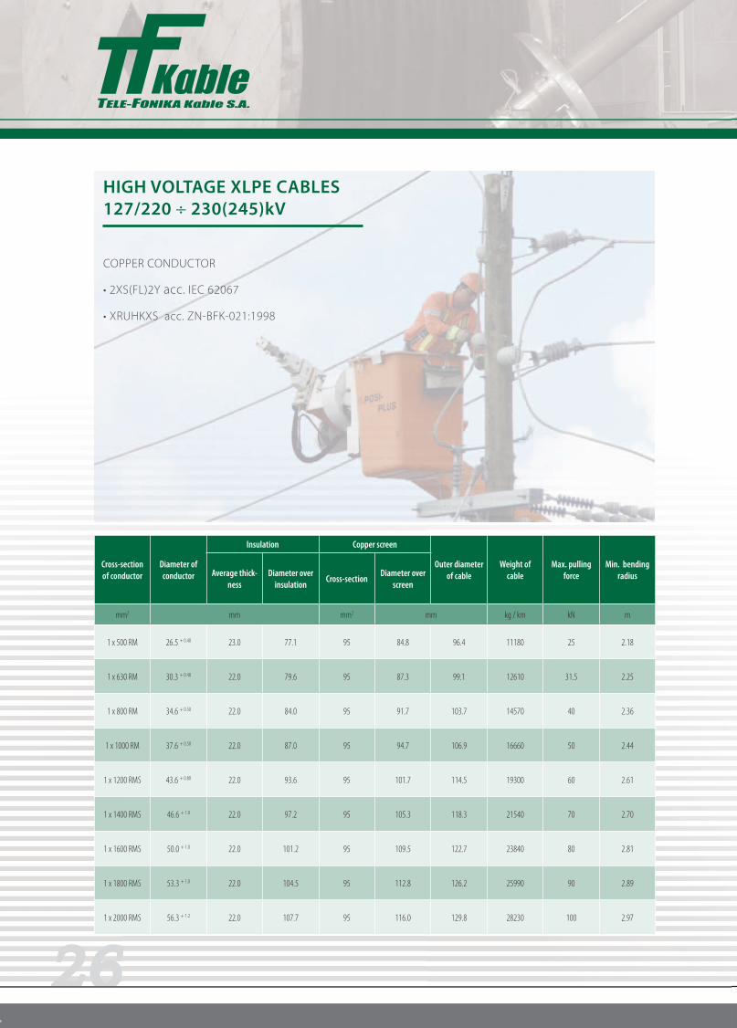
HIGH VOLTAGE XLPE CABLES127/220 230(245)kV
COPPER CONDUCTOR
acc. IEC 62067
Cross-section of conductor
Diameter of conductor
Insulation Copper screen
Outer diameter of cable
Weight of cable
Max. pulling force
Min. bending radiusAverage thick-
nessDiameter over
insulationCross-section
Diameter over screen
mm2 mm mm2 mm kg / km kN m
1 x 500 RM 26.5 + 0.40 23.0 77.1 95 84.8 96.4 11180 25 2.18
1 x 630 RM 30.3 + 0.40 22.0 79.6 95 87.3 99.1 12610 31.5 2.25
1 x 800 RM 34.6 + 0.50 22.0 84.0 95 91.7 103.7 14570 40 2.36
1 x 1000 RM 37.6 + 0.50 22.0 87.0 95 94.7 106.9 16660 50 2.44
1 x 1200 RMS 43.6 + 0.80 22.0 93.6 95 101.7 114.5 19300 60 2.61
1 x 1400 RMS 46.6 + 1.0 22.0 97.2 95 105.3 118.3 21540 70 2.70
1 x 1600 RMS 50.0 + 1.0 22.0 101.2 95 109.5 122.7 23840 80 2.81
1 x 1800 RMS 53.3 + 1.0 22.0 104.5 95 112.8 126.2 25990 90 2.89
1 x 2000 RMS 56.3 + 1.2 22.0 107.7 95 116.0 129.8 28230 100 2.97

27
ELECTRICAL PARAMETERS
RM – round multiwire conductor
RMS – round multiwire segmented conductor (Milliken construction)
/1 – trefoil formation
/2 – phase distance at flat formation = 2 x cable diameter
/3 – phase distance at flat formation = 70 mm + cable diameter
/4 – SPB – Single Point Bonding; CB – Cross-bonding; Both-ends – Both-ends Bonding
Cross-section of conductor
Conductor resistance Copper screen resistance Field strengthat conductor
screen / insulation
Max. short circuit current
Capacitance
InductanceoOo /1
o o o /2
o o o /3
Ampacity
DC20 OC AC90 OC DC20 OC AC80 OC ConductorCopper screen
In ground In air
SPB, CB /4 o o o / oOo
Both-ends /4 o o o / oOo
mm2 Ω / km kV / mm kA / 1 sec µF / km mH / km A
1 x 500 RM 0.0366 0.0489 0.215 0.266 8.97 / 3.50 71.5 19.29 0.14 0.440.630.60825 / 785 1113 / 992
650 / 730 903 / 940
1 x 630 RM 0.0283 0.039 0.215 0.266 8.81 / 3.83 90.09 19.29 0.15 0.420.610.58940 / 890 1297 / 1139
705 / 810 998 / 1061
1 x 800 RM 0.0221 0.0319 0.215 0.266 8.49 / 3.94 114.4 19.29 0.17 0.410.590.551055 / 995 1486 / 1297
755 / 885 1092 / 1187
1 x 1000 RM 0.0176 0.0268 0.215 0.266 8.30 / 4.01 143 19.29 0.18 0.390.580.541165 / 1095 1670 / 1449
800 / 950 1181 / 1307
1 x 1200 RMS 0.0151 0.0204 0.215 0.266 7.97 / 4.14 171.6 19.29 0.19 0.380.560.521345 / 1280 1974 / 1733
860 / 1055 1302 / 1496
1 x 1400 RMS 0.0129 0.0177 0.215 0.266 7.83 / 4.20 200.2 19.29 0.21 0.370.560.511455 / 1385 2168 / 1890
890 / 1110 1365 / 1601
1 x 1600 RMS 0.0113 0.0159 0.215 0.266 7.68 / 4.27 228.8 19.29 0.22 0.370.550.501550 / 1470 2347 / 2037
920 / 1155 1423 / 1696
1 x 1800 RMS 0.0101 0.0146 0.215 0.266 7.58 / 4.32 257.4 19.29 0.23 0.360.540.491627 / 1537 2485 / 2145
938 / 1187 1460 / 1762
1 x 2000 RMS 0.009 0.0134 0.215 0.266 7.49 / 4.36 286 19.29 0.24 0.350.540.491705 / 1605 2625 / 2252
955 / 1220 1496 / 1827

28
HIGH VOLTAGE XLPE CABLES 127/220 230(245)kV
acc. IEC 62067
Cross-section of conductor
Diameter of conductor
Insulation Copper screen
Outer diameter of cable
Weight of cable
Max. pulling force
Min. bending radiusAverage thick-
nessDiameter over
insulationCross-section
Diameter over screen
mm2 mm mm2 mm kg / km kN m
1 x 500 RM 25.7 + 0.40 23.0 76.3 95 84.0 95.4 7990 15.0 2.17
1 x 630 RM 29.3 + 0.50 22.0 78.7 95 86.4 98.0 8540 18.9 2.23
1 x 800 RM 33.0 + 0.50 22.0 82.4 95 90.0 102.1 9390 24.0 2.32
1 x 1000 RM 38.0 + 0.50 22.0 87.4 95 95.0 107.3 10460 30.0 2.45
1 x 1200 RM 41.0 + 0.60 22.0 90.7 95 98.8 114.4 11500 36.0 2.54
1 x 1200 RMS 43.6 + 0.80 22.0 93.6 95 101.7 114.5 11900 36.0 2.61
1 x 1400 RMS 46.6 + 1.0 22.0 97.2 95 105.3 118.3 12860 42.0 2.70
1 x 1600 RMS 50.0 + 1.0 22.0 101.2 95 109.5 122.7 13930 48.0 2.81
1 x 1800 RMS 53.3 + 1.0 22.0 104.5 95 112.8 126.2 14850 54.0 2.89
1 x 2000 RMS 55.4 + 1.2 22.0 106.8 95 115.1 128.7 15580 60.0 2.95

29
ELECTRICAL PARAMETERS
RM – round multiwire conductor
RMS – round multiwire segmented conductor (Milliken construction)
/1 – trefoil formation
/2 – phase distance at flat formation = 2 x cable diameter
/3 – phase distance at flat formation = 70 mm + cable diameter
/4 – SPB – Single Point Bonding; CB – Cross-bonding; Both-ends – Both-ends Bonding
Cross-section of conductor
Conductor resistance Copper screen resistance Field strengthat conductor
screen / insulation
Max. short circuit current
Capacitance
InductanceoOo /1
o o o /2
o o o /3
Ampacity
DC20 OC AC90 OC DC20 OC AC80 OC ConductorCopper screen
In ground In air
SPB, CB /4 o o o / oOo
Both-ends /4 o o o / oOo
mm2 Ω / km kV / mm kA / 1 sec µF / km mH / km A
1 x 500 RM 0.0605 0.0790 0.215 0.266 9.06 / 3.48 47.25 19.29 0.13 0.450.630.60645 / 620 877 / 782
555 / 595 761 / 756
1 x 630 RM 0.0469 0.0620 0.215 0.266 8.89 / 3.81 59.54 19.29 0.15 0.430.610.58740 / 710 1024 / 908
610 / 670 861 / 872
1 x 800 RM 0.0367 0.0495 0.215 0.266 8.60 / 3.90 75.6 19.29 0.16 0.410.600.56845 / 805 1187 / 1045
665 / 745 956 / 987
1 x 1000 RM 0.0291 0.0404 0.215 0.266 8.28 / 4.02 94.5 19.29 0.18 0.390.580.54950 / 900 1360 / 1192
720 / 820 1055 / 1108
1 x 1200 RM 0.0247 0.0353 0.215 0.266 8.11 / 4.09 113.4 19.29 0.19 0.390.570.531025 / 970 1491 / 1297
755 / 870 1124 / 1197
1 x 1200 RMS 0.0247 0.0324 0.215 0.266 7.97 / 4.14 113.4 19.29 0.19 0.380.560.521025 / 970 1491 / 1297
755 / 870 1124 / 1197
1 x 1400 RMS 0.0212 0.0280 0.215 0.266 7.83 / 4.20 132.3 19.29 0.21 0.370.560.511100 / 1040 1622 / 1402
785 / 915 1181 / 1281
1 x 1600 RMS 0.0186 0.0248 0.215 0.266 7.68 / 4.27 151.2 19.29 0.22 0.370.550.501165 / 1095 1733 / 1491
815 / 955 1229 / 1349
1 x 1800 RMS 0.0165 0.0223 0.215 0.266 7.58 / 4.32 170.1 19.29 0.23 0.360.540.491220 / 1145 1832 / 1570
835 / 985 1271 / 1407
1 x 2000 RMS 0.0149 0.0203 0.215 0.266 7.51 / 4.35 189.0 19.29 0.23 0.360.540.491275 / 1190 1932 / 1649
855 / 1015 1313 / 1465

30
DELIVERY OF CABLE SYSTEMS
Tele-Fonika Kable S.A. has a extensive experience in offering HV systems worldwide. Starting in 1992 with first
installation of 110kV XLPE cable system in Poland so far Tele-Fonika has realize over 100 of HV system projects
all over the world. The “turn key” solution includes design of the system, site surveys, cable-laying, installation
and final test.
CABLE AND ACCESSORIES SELECTION
Tele-Fonika Kable S.A. offers selection of cables and equipment adequate to required technical-operational
parameters of designed cable systems, in cooperation with design offices and investors.
selection of nominal cross-section of cable conductor, based on required load capacity of cable line and
performance conditions
selection of nominal cross-section metallic screen, based on short-circuit loads of energy system and time
of their duration.
area of cable laying: ground, air, ducts, flyover
number of cable lines and distances between them
method of cable laying (flat or triangular)
depth of laying under ground with respect to thermal resistance of soil
designed culverts and their length
selection of types and quantities of cable accessories, based on atmospheric pollution level and available cable
sections offered by the producer.

31

32