9371-fb-px-pp – 6-spur 9373-fb-px-pp –12-spur · inm9370-pp-2 iii may 2012 declaration of...
TRANSCRIPT

Instruction Manual
INM9370-PP
9371-FB-Px-PP – 6-spur9373-FB-Px-PP – 12-spurFieldbus Barrier System - GRP enclosure

ii INM9370-PP-2 May 2012

iiiINM9370-PP-2 May 2012
DECLARATION OF CONFORMITY
We declare under our sole responsibility that the MTL937x-FB-Px-xx systems, 938x-FB-xx internal assemblies and associated products listed in Annex 1 overleaf, to which this declaration relates, conform with the requirements of the Directives below by compliance with the standards listed:
1. Council Directive 2004/108/EC (EMC Directive) relating to Electro-Magnetic Compatibility. EN 61326-1:2006 Table 2 - Industrial Locations: Class A equipment
2. Council Directive 2006/95/EC (Low Voltage Directive) relating to Product Safety. EN 61010-1:2010
3. Council Directive 94/9/EC (ATEX Directive) relating to equipment and protective systems intended for use in potentially explosive atmospheres. EN 60079-0:2009; EN 60079-1:2007; EN 60079-7:2007; EN 60079-11:2007; EN 60079-18:2009; EN 60079-27:2008; EN 60079-18:2004; EN 60079-27:2006; IEC60079-31:2008
3rd May 2012
Luton, England
Signed: J.N. Malins J.N.Malins - Technical Director
Measurement Technology LimitedGreat Marlings, Butterfield, Luton
Bedfordshire, United Kingdom LU2 8DLTel: +44 (0)1582 723633
Fax: +44 (0)1582 422283 www.mtl-inst.com
Registered in England No. 1012778

iv INM9370-PP-2 May 2012
Annex 1 - Conforming Products
Product Description EMC1 LVD2 ATEX3 Cat1/Cat2 ATEX Cert No.
Cat2 ATEX Cert
No.
9371-FB-PS-SS Fieldbus barrier system, 6-spur, stainless steel enclosure, pluggable screw terminal connectors Yes Yes Yes Baseefa 09 ATEX 0185X/3# N/A
9371-FB-PC-SS Fieldbus barrier system, 6-spur, stainless steel enclosure, pluggable spring clamp connectors Yes Yes Yes Baseefa 09 ATEX 0185X/3# N/A
9373-FB-PS-SS Fieldbus barrier system, 12-spur, stainless steel enclosure, pluggable screw terminal connectors Yes Yes Yes Baseefa 09 ATEX 0185X/3# N/A
9373-FB-PC-SS Fieldbus barrier system, 12-spur, stainless steel enclosure, pluggable spring clamp connectors Yes Yes Yes Baseefa 09 ATEX 0185X/3# N/A
9371-FB-PS-PP Fieldbus barrier system, 6-spur, GRP enclosure, pluggable screw terminal connectors Yes Yes Yes Baseefa 09 ATEX 0185X/3# N/A
9371-FB-PC-PP Fieldbus barrier system, 6-spur, GRP enclosure, pluggable spring clamp connectors Yes Yes Yes Baseefa 09 ATEX 0185X/3# N/A
9373-FB-PS-PP Fieldbus barrier system, 12-spur, GRP enclosure, pluggable screw terminal connectors Yes Yes Yes Baseefa 09 ATEX 0185X/3# N/A
9373-FB-PC-PP Fieldbus barrier system, 12-spur, GRP enclosure, pluggable spring clamp connectors Yes Yes Yes Baseefa 09 ATEX 0185X/3# N/A
9371/4-FB-PS-SS Fieldbus barrier system, 4-spur, stainless steel enclosure, pluggable screw terminal connectors Yes Yes Yes Baseefa 09 ATEX 0185X/1 N/A
9371/4-FB-PC-SS Fieldbus barrier system, 4-spur, stainless steel enclosure, pluggable spring clamp connectors Yes Yes Yes Baseefa 09 ATEX 0185X/1 N/A
9373/8-FB-PS-SS Fieldbus barrier system, 8-spur, stainless steel enclosure, pluggable screw terminal connectors Yes Yes Yes Baseefa 09 ATEX 0185X/1 N/A
9373/8-FB-PC-SS Fieldbus barrier system, 8-spur, stainless steel enclosure, pluggable spring clamp connectors Yes Yes Yes Baseefa 09 ATEX 0185X/1 N/A
9371/4-FB-PS-PP Fieldbus barrier system, 4-spur, GRP enclosure, pluggable screw terminal connectors Yes Yes Yes Baseefa 09 ATEX 0185X/1 N/A
9371/4-FB-PC-PP Fieldbus barrier system, 4-spur, GRP enclosure, pluggable spring clamp connectors Yes Yes Yes Baseefa 09 ATEX 0185X/1 N/A
9373/8-FB-PS-PP Fieldbus barrier system, 8-spur, GRP enclosure, pluggable screw terminal connectors Yes Yes Yes Baseefa 09 ATEX 0185X/1 N/A
9373/8-FB-PC-PP Fieldbus barrier system, 8-spur, GRP enclosure, pluggable spring clamp connectors Yes Yes Yes Baseefa 09 ATEX 0185X/1 N/A
9376-SP Trunk surge module Yes Yes Yes Baseefa 09 ATEX 0324U# N/A9378-FT Trunk terminator module Yes Yes Yes Baseefa 09 ATEX 0323U# N/A
9387-FB-PS Fieldbus barrier internal assembly, 6-spur, pluggable screw terminal connectors Yes Yes Yes Baseefa 09 ATEX 0184U*# N/A
9387-FB-PC Fieldbus barrier internal assembly, 6-spur, pluggable spring clamp connectors Yes Yes Yes Baseefa 09 ATEX 0184U*# N/A
9388-FB-PS Fieldbus barrier internal assembly, 12-spur, pluggable screw terminal connectors Yes Yes Yes Baseefa 09 ATEX 0184U*# N/A
9388-FB-PC Fieldbus barrier internal assembly, 12-spur, pluggable spring clamp connectors Yes Yes Yes Baseefa 09 ATEX 0184U*# N/A
9387-FB-PS-R Fieldbus barrier redundant internal assembly, pluggable screw terminal connectors Yes Yes Yes Baseefa 09 ATEX 0184U*# N/A
9387-FB-PC-R Fieldbus barrier redundant internal assembly, pluggable spring clamp connectors Yes Yes Yes Baseefa 09 ATEX 0184U*# N/A
9372-FB-PS-SS Fieldbus barrier redundant, stainless steel enclosure, pluggable screw terminal connectors Yes Yes Yes Baseefa 09 ATEX 0185X/3# N/A
9372-FB-PC-SS Fieldbus barrier redundant, stainless steel enclosure, pluggable spring clamp connectors Yes Yes Yes Baseefa 09 ATEX 0185X/3# N/A
9372-FB-PS-PP Fieldbus barrier redundant, GRP enclosure, pluggable screw terminal connectors Yes Yes Yes Baseefa 09 ATEX 0185X/3# N/A
9372-FB-PC-PP Fieldbus barrier redundant, GRP enclosure, pluggable spring clamp connectors Yes Yes Yes Baseefa 09 ATEX 0185X/3# N/A
* For products highlighted with a *, IEC60079-31:2008 does not apply # Products highlighted with a #, have been tested to EN 60079-18:2009 and EN 60079-27:2008
Notes relating to CE Marking:
1. Entries in this column may be: Yes Product conforms to the EMC Directive N/R Product is not required to conform to the EMC Directive
2. Entries in this column may be: Yes Product conforms to the EMC Directive N/R Product is not required to conform to the EMC Directive
3. Entries in this column may be: Yes Product conforms to the ATEX Directive N/R Product is not required to conform to the ATEX Directive
4 All items equipment group II, category 2, gas group IIC
Notified Body responsible for Cat I or 2 ATEX Certificates: Baseefa, Rockhead Business Park, Staden Lane, Buxton, Derbyshire, SK 17 9RZ. Notified body number 1180.

vINM9370-PP-2 May 2012
CONTENTS
1 OVERVIEW . . . . . . . . . . . . . . . . . . . . . . . . . . . . . . . . . . . . . . . . . . . . . . . . . . . . . . . . . . 1
2 DESCRIPTION . . . . . . . . . . . . . . . . . . . . . . . . . . . . . . . . . . . . . . . . . . . . . . . . . . . . . . . . 2
3 MECHANICAL INSTALLATION . . . . . . . . . . . . . . . . . . . . . . . . . . . . . . . . . . . . . . . . . . . . 23 .1 Mounting overview . . . . . . . . . . . . . . . . . . . . . . . . . . . . . . . . . . . . . . . . . . . . . . . . . . . . . . .23 .2 Preparation . . . . . . . . . . . . . . . . . . . . . . . . . . . . . . . . . . . . . . . . . . . . . . . . . . . . . . . . . . . . .43 .3 Mounting . . . . . . . . . . . . . . . . . . . . . . . . . . . . . . . . . . . . . . . . . . . . . . . . . . . . . . . . . . . . . . .4
4 INITIAL ELECTRICAL INSTALLATION . . . . . . . . . . . . . . . . . . . . . . . . . . . . . . . . . . . . . . . . 54 .1 Overview . . . . . . . . . . . . . . . . . . . . . . . . . . . . . . . . . . . . . . . . . . . . . . . . . . . . . . . . . . . . . . .54 .2 Grounding . . . . . . . . . . . . . . . . . . . . . . . . . . . . . . . . . . . . . . . . . . . . . . . . . . . . . . . . . . . . . .54 .3 Trunk connections . . . . . . . . . . . . . . . . . . . . . . . . . . . . . . . . . . . . . . . . . . . . . . . . . . . . . . . . .74 .4 Trunk Terminator module 9378-FT . . . . . . . . . . . . . . . . . . . . . . . . . . . . . . . . . . . . . . . . . . .104 .5 Trunk Surge module 9376-SP . . . . . . . . . . . . . . . . . . . . . . . . . . . . . . . . . . . . . . . . . . . . . . .104 .6 Spur connections . . . . . . . . . . . . . . . . . . . . . . . . . . . . . . . . . . . . . . . . . . . . . . . . . . . . . . . .104 .7 Final checks . . . . . . . . . . . . . . . . . . . . . . . . . . . . . . . . . . . . . . . . . . . . . . . . . . . . . . . . . . . .11
5 MAINTENANCE . . . . . . . . . . . . . . . . . . . . . . . . . . . . . . . . . . . . . . . . . . . . . . . . . . . . . . 115 .1 General . . . . . . . . . . . . . . . . . . . . . . . . . . . . . . . . . . . . . . . . . . . . . . . . . . . . . . . . . . . . . . .115 .2 Fieldbus Barrier - fitting and removal . . . . . . . . . . . . . . . . . . . . . . . . . . . . . . . . . . . . . . . . .125 .3 Terminator and Trunk Surge Protection modules . . . . . . . . . . . . . . . . . . . . . . . . . . . . . . . . .135 .4 Spur connections . . . . . . . . . . . . . . . . . . . . . . . . . . . . . . . . . . . . . . . . . . . . . . . . . . . . . . . .145 .5 Trunk connections . . . . . . . . . . . . . . . . . . . . . . . . . . . . . . . . . . . . . . . . . . . . . . . . . . . . . . . .155 .6 Regular Maintenance checks . . . . . . . . . . . . . . . . . . . . . . . . . . . . . . . . . . . . . . . . . . . . . . .15
6 TROUBLESHOOTING . . . . . . . . . . . . . . . . . . . . . . . . . . . . . . . . . . . . . . . . . . . . . . . . . . 16
7 ATEX INFORMATION . . . . . . . . . . . . . . . . . . . . . . . . . . . . . . . . . . . . . . . . . . . . . . . . . 177 .1 General . . . . . . . . . . . . . . . . . . . . . . . . . . . . . . . . . . . . . . . . . . . . . . . . . . . . . . . . . . . . . . .177 .2 Installation . . . . . . . . . . . . . . . . . . . . . . . . . . . . . . . . . . . . . . . . . . . . . . . . . . . . . . . . . . . . .177 .3 Inspection and maintenance . . . . . . . . . . . . . . . . . . . . . . . . . . . . . . . . . . . . . . . . . . . . . . .177 .4 Repair . . . . . . . . . . . . . . . . . . . . . . . . . . . . . . . . . . . . . . . . . . . . . . . . . . . . . . . . . . . . . . . .187 .5 Marking . . . . . . . . . . . . . . . . . . . . . . . . . . . . . . . . . . . . . . . . . . . . . . . . . . . . . . . . . . . . . . .18
8 APPENDIX 1 - ENCLOSURE WIRING DIAGRAMS . . . . . . . . . . . . . . . . . . . . . . . . . . . . . 198 .1 Wiring diagram for 9371-FB-Px-PP . . . . . . . . . . . . . . . . . . . . . . . . . . . . . . . . . . . . . . . . . .208 .2 Wiring diagram for 9373-FB-Px-PP . . . . . . . . . . . . . . . . . . . . . . . . . . . . . . . . . . . . . . . . . .21
© 2012 MTL Instruments Group . All rights reserved
vi INM9370-PP-2 May 2012
GENERAL SAFETY INFORMATIONSafety instructions for installation and operating personnel
The operating instructions provided here contain essential safety instructions for installation personnel and those engaged in the operation, maintenance and servicing of the equipment.
WARNING!
Failure to comply with these instructions can endanger the lives or health of personnel and risk damage to the plant and the environment .
WARNING!
The responsibility for planning, installation, commissioning, operation and maintenance, particularly with respect to applications in explosion-hazard areas, lies with the plant operator .
Before commencing installation or commissioning:
• Read and understand the contents of this manual
• Ensure installation and operating personnel have received adequate training for this task
• Ensure that any operating instructions are fully understood by the personnel responsible.
• Observe national and local installation and mounting regulations (e.g. IEC 60079-14).
WARNING!
These assemblies may not be used in explosion-hazard area applications if they have been used previously in general electrical installations .
During operation:
• Make the relevant instructions available at all times to the operating personnel.
• Observe safety instructions.
• Observe national safety and accident prevention regulations.
• Operate the equipment within its published specification.
• Servicing, maintenance work or repairs not described in this manual must not be performed without prior agreement with the manufacturer.
• Any damage to this equipment may render its explosion protection null and void.
• No changes to any of the components that might impair their explosion protection are permitted.
If any information provided here is not clear:
• Contact MTL or one of its representatives.
Note: Improper installation and operation of the enclosure can result in the invalidation of the guarantee.
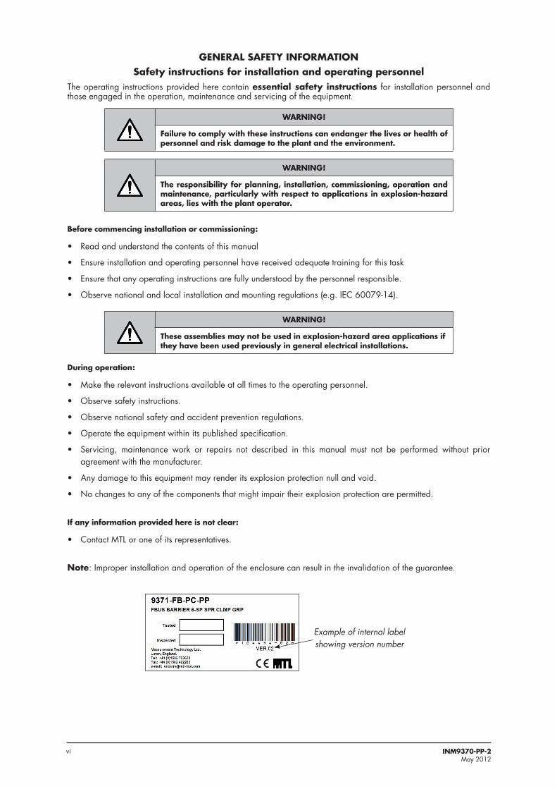
Example of internal label showing version number

1INM9370-PP-2 May 2012
9377-FB-R - fieldbus barriers
FS32 - spur surge protection module
9378-FT - fieldbusterminator module
Trunk terminalassembly (TTA)
Carrier
Protectiveground stud
Spur connectorsSpur outputs
Trunk input/output
Breather
1 OVERVIEW
IMPORTANT: Enclosures from Version 3 onwards are fitted with the latest type of fieldbus barrier, the 9377-FB-R. The earlier 9377-FB barrier cannot be fitted to the Version 3 (and later) enclosures, but the newer barrier can be retro-fitted to earlier Version 1 and Version 2 enclosures. The 9377-FB-R modules have similar or improved electrical specifications to 9377-FB in every respect - see datasheet.(Note: The enclosure version number is below the bar code on the product label on the right-hand inside wall of the enclosure - see label example on page iv opposite.)
This manual explains the installation and maintenance procedures for the 937x-FB-Px-PP Fieldbus Barrier enclosures and must be read in association with the product datasheets that contain the electrical data.
The 9371-FB-Px-PP and 9373-FB-Px-PP Fieldbus Barrier enclosures are field-mounted wiring hubs that create six or twelve intrinsically safe spur connections, respectively, from a single non-intrinsically safe trunk, for connection to Foundation™ fieldbus H1 fieldbus instruments. The incoming fieldbus trunk and the output spurs may optionally be fitted with surge-protection devices.
The enclosure material is glass reinforced plastic (GRP) and may be installed in a Zone 1 or Zone 2 hazardous area.
The following enclosure types are available by ordering the appropriate model number.
9371-FB-Px-PP Fieldbus Barrier system, 6-spur, GRP enclosure
9373-FB-Px-PP Fieldbus Barrier system, 12-spur, GRP enclosure
Where Px = PS (pluggable screw terminal connectors) or PC (pluggable spring clamp connectors)
937x-FB-Px-PP Fieldbus Barrier System 6- & 12-spur, GRP enclosure
INM9370-PP-2 May 2012
Figure 1 .1 - Example of model 9373-FB-PS-PP with one FS32 spur surge protection module

2 INM9370-PP-2 May 2012
2 DESCRIPTIONThe model numbers given comprise a GRP, increased safety, Ex e enclosure containing one or two carrier-mounted fieldbus barriers. A single barrier module converts a single, non-intrinsically safe fieldbus trunk into six intrinsically safe (IS) spur connections for connection to Foundation™ fieldbus H1 fieldbus instruments.
Inside the enclosure, the incoming trunk wiring enters a separate compartment, called the Trunk Terminal Assembly (TTA) that contains increased safety (Ex e) trunk wiring terminals. This assembly has a protective cover to deter interference, and carries a warning to the user about working on trunk wiring without first isolating the power.
A fieldbus Terminator module (part no. 9378-FT) is supplied pre-fitted on the TTA. This is to remain installed if the enclosure is at the end of the segment. If the incoming fieldbus trunk will be onward linked to a further node on the segment the terminator can be removed.
The spurs are galvanically isolated from the trunk allowing the user to choose the type of grounding scheme most suitable to their system.
Spur short-circuit protection is provided by the barrier and surge protection can also be added on individual outgoing spurs by the use of individual Spur Surge protection modules (part no. FS32).
An optional Trunk Surge module (part no. 9376-SP) can be plugged into the TTA to protect the fieldbus barrier against damaging voltage and current surges on the incoming trunk wiring.
The enclosures may be installed in a Zone 1 or Zone 2 hazardous area; in which case, the trunk wiring must be implemented using suitably protected cable.
The GRP enclosures provide excellent chemical and moisture resistance and are suitable for use in a wide range of corrosive environments.
The 937x-FB-Px-PP fieldbus barrier enclosures are bus-powered and they require no additional power supply in the field. When used with a fieldbus host control system, power for the trunk MUST be provided only by a supply conforming to IEC 61158-2, e.g. MTL-Relcom F800 or MTL 918x Series redundant power supplies.
The enclosures are supplied pre–drilled for all trunk and spur cable entries and fitted with Ex e certified blanking plugs and a breather .
3 MECHANICAL INSTALLATIONSee Figures 3.1 and 3.2 for the dimensions, fixing locations and cable gland positions for both enclosure models.
3 .1 Mounting overviewBefore mounting an enclosure, consider the following points.
a) The permitted ambient temperature range external to the enclosure (–40°C to +65°C) must not be exceeded. Avoid radiant heat by locating the enclosure away from direct sunlight or local sources of heat.
b) The enclosure has an ingress protection rating of IP65 (to EN60529) so the mounting location should be chosen to comply with this rating.
c) The enclosure is designed for mounting on a vertical surface, with the cable entry at the lowest point, as shown in the upper part of Figure 3.1 or Figure 3.2.
d) The nominal weight of the enclosures, excluding any surge protection modules (trunk or spur) is:
Model type Nominal weight
9371-FB-Px-PP 4.5 kg
9373-FB-Px-PP 8.2 kg

3INM9370-PP-2 May 2012
������������������������������������������� ������������ ���
�
����
��
��
��������
�
������������������������������
���������������
������������������������������ ������������������������
������������������
����������������������������� ������������������� �������������������
��������������������������������������������������������������������������������������
������������������������������������������������������������������������� ���� � �������������
������
���� �������� �����������������������������������
����� �������
�������
Figure 3 .1 - External dimensions and mounting hole positions for the 6-way enclosure (9371-FB-Px-PP)
Figure 3 .2 - External dimensions and mounting hole positions for the 12-way enclosure (9373-FB-Px-PP)
��� ���
���
����
�����
����
���
�����
����
����� �����
���
������������� ������������������������ ������������������������������������������ ����������������������� ���������
������������������������������
���������������
������������������������������ ������������������������
������������������
����������������������������� ������������������� �������������������
��������������������������������������������������������������������������������������
������������������������������������������������������������������������� ��� � �������������
������
���� �������� ������������������������������������
���
����� �������

4 INM9370-PP-2 May 2012
e) Adequate security should be provided against unauthorised interference.f) All the necessary gland holes have been prepared in the enclosure. One has a breather
fitted and the others are fitted with appropriate blanking plugs. Where the blanking plugs are replaced by cable gland, the fitted glands must be Ex e certified and have an ingress protection (IP) rating that maintains the overall rating of the enclosure.
g) All cable gland holes must be fitted with either a suitable cable gland or blanking plug.
WARNING!
It is not permitted to create additional holes in the enclosure as this would violate the certification .
3 .2 Preparationa) Remove any temporary protection or packing materials.b) The enclosure can be mounted on any suitable structure using the enclosure’s integral
mounting facilities.c) The fixing bolts must be suitable for the mounting surface and the environmental
conditions.d) It is advisable before mounting, to do any necessary replacement of the cable entry
blanking plugs with a suitable gland. For further details see Section 3.1 e) & f).
3 .3 Mounting
WARNING!
To minimise the risk of ignition by electrical apparatus in hazardous areas, efficient installation, inspection and maintenance of apparatus and systems is essential, and the work should be carried out by suitably trained personnel in accordance with the prevailing code of practice .
The certification documents specify “Conditions for safe use” that must be adhered to and the copy certificate supplied should be studied and understood . Additionally it is recommend that a working knowledge of IEC EN 60079 -14 be attained, as this standard provides guidance in respect to the installation of electrical equipment in hazardous areas .
3 .3 .1 Fixing the enclosure to a surface
Mark hole positions as shown in Figures 3.1 or 3.2.
NOTE
For the 9373-FB, it is important to recognise that the hole centres for the middle fixings are not aligned with the holes for the end fixings. Use the dimensions indicated as (F) in Figure 3.2.
Open up these hole positions to a suitable size and depth.
a) It is recommended that a washer, not exceeding the 12mm diameter specified in Figures 3.1 and 3.2, is placed under the head of each of the bolts used to fix the enclosure to its mounting surface.
b) It is suggested that the lower fixings should be put in place first, so that the enclosure can be supported by them while the upper fixings are put in place.
After mounting the enclosure Check that:
• it has not suffered any damage,
• the IP rating is not affected; for example, by distortion of the enclosure,
• the mounting bolts/nuts are all tightened as recommended above.

5INM9370-PP-2 May 2012
4 INITIAL ELECTRICAL INSTALLATION
WARNING!
Before starting any electrical installation work, ensure that the incoming trunk connection is isolated from any source of power .
CAUTION
The temperature inside the enclosure could rise to 75°C . Ensure that all cables and cable glands fitted are rated to withstand these temperatures .
4 .1 OverviewObtain access to the contents of the enclosure by removing the lid which is secured to the body of the enclosure by captive screws. Loosen these screws to obtain entry.
CAUTION
The lid is connected to the enclosure body with a protective grounding cable .DO NOT leave the lid hanging by this link cable while work is carried out!
• The enclosure receives power from the incoming trunk cable and requires no further source of power.
• The equipment shall only be powered from supplies conforming to IEC 61158.
• Type ‘A’ fieldbus cable is recommended for fieldbus trunk connections.
• The terminal blocks for the trunk fieldbus cables have either screw terminal connectors or cage clamp connectors according to the enclosure model specified, but both are suitable for cables from 0.5mm2/AWG 20 up to 2.5mm2/AWG 14.
Check all blanking plugs and cable glands are tightened to ensure at least an IP65 rating.
For details of the enclosure wiring for the two system types see Appendix 1.
4 .2 GroundingTwo distinct ground concepts should be recognised before wiring of the enclosure begins:
a) Protective local ground - mandatoryb) Cable shield groundThese two concepts and their implementation are explained below.
4 .2 .1 Protective local ground
This ground connection is required to ensure that any exposed metal work in, or on, the enclosure does not present a hazard to personnel; it also provides a low impedance earth-grounding circuit for any surge protection items used in the enclosure. An M8 earth-grounding stud is provided on the side wall of the enclosure to enable a connection to be made to the local ground.
Use a ring terminal to make a good quality, plant safety earth connection (4mm2 cross-sectional area or better) to this bolt and tighten it to a recommended torque of 5Nm.
Note: It is important to prevent this connection from loosening and also to protect it from corrosion against the stainless steel grounding stud.
Where the trunk and spur cables are protected by steel wire armour, this should be treated as part of the “protective” ground. Normal practice is to bond the armour to the plant structure at both ends of each cable. Where armour-protected cables enter the Fieldbus Barrier enclosure, the armour must be connected to the enclosure body using suitable cable glands.
4 .2 .2 Cable shield ground
The cable shield is normally electrically isolated from the protective earth ground, although the two may be deliberately interconnected in some grounding arrangements. The cable shield wiring of the trunk and spur cables should be connected to the local terminals marked with an ‘S’.

6 INM9370-PP-2 May 2012
The enclosures can be configured by the user to either of two grounding methods. The user should adopt the one that conforms to their system’s normal grounding method.
Whichever method is used, it is important to connect the screen/shield to a ground at only one end of the cable. The following options are available to the user.
WARNING!
The following may involve changes to wiring in the Trunk Terminal Assembly . No part of the Trunk Terminal Assembly may be worked while the enclosure is powered, unless the environment is known to be non-hazardous .
4 .2 .2 .1 Single point of grounding at host; trunk & spur shields interconnected
����������������������������
��� ���������������
���������� ��
�����������
� �
� �� �� ��
���������
�� ������
�����������
������� ��
�
Figure 4 .1 - Option 1
In many installations, the preferred method of grounding is to ground the fieldbus cable shields at one point only, normally at the fieldbus power supply. In this case, the trunk and spur cable shields are connected to each other at the Fieldbus Barrier and are not connected to ground in the field. For this arrangement, connect the carrier shield ground wire (Cable A) into Terminal 2. Note: this is the default grounding method for factory-supplied 937x-FB enclosures.
IMPORTANT NOTE
937x-FB enclosures are factory-supplied with Option 1 grounding . If power is applied locally, for example during commissioning, when the trunk cable shield is NOT providing a ground connection, the spur cable shields must be grounded according to Option 2 . When the trunk cable shield ground has been fully instated (or restored), the grounding method should be returned to Option 1 .
4 .2 .2 .2 Trunk shield grounded at host; spur cable shields grounded at barrier
�������������������
������������
�� ������������������
������
�������������
� �
� �� �� ��
�����������
���������
������������
���������� �
Figure 4 .2 - Option 2
With this arrangement, the fieldbus trunk shield is separated from the spur cable shields. It should be adopted if plant or local regulations require that the spur cable shields be grounded at the Fieldbus Barrier. For this arrangement, connect the carrier shield ground wire (Cable A) into Terminal 3.
Note: After configuring the required grounding option, tighten all screw terminals to a recommended torque of 0.6 Nm.

7INM9370-PP-2 May 2012
4 .3 Trunk connectionsEach enclosure is provided with two access holes for trunk glands; one for the incoming trunk and another for onward linking to an additional enclosure, if necessary.
WARNING!
No part of the Trunk Terminal Assembly may be worked while the enclosure is powered, unless the environment is known to be non-hazardous .
4 .3 .1 Trunk Terminal Assembly
Inside the enclosure, the trunk cables are terminated in a Trunk Terminal Assembly (TTA). This is a sub-enclosure with a protective lid, secured with a single screw. This assembly, together with its warning label, is intended to deter a user from working on the trunk connections without isolating trunk power. See Figure 4.6.
Trunk cables enter via glands, through the enclosure wall shown at the bottom of the diagram, and the grounding stud is accessible on the lower left side. The trunk terminal connectors are in the middle of the assembly to receive the trunk wiring.
Depending upon model type chosen, the enclosure will accommodate 6 or 12 spurs.
Terminals are provided to allow a variety of wiring arrangements, according to the particular requirements of the installation:
– “Trunk In” cable only – “Trunk In” and “Trunk Out” cables – Active and spare “Trunk In” cables – Active and spare “Trunk In” cables with overall cable shield – Active and spare “Trunk In” cables and “Trunk Out” cable
CAUTION
The ‘+’ and ‘–’ wires of a ‘spare’ trunk in cable must be connected only to terminals marked ‘NC’ . This ensures that the spare cable is not electrically connected in parallel with the ‘active’ trunk in or trunk out cables . The cable shield of the spare cable should be connected to an ‘S’ terminal .
All ‘spare’ trunk-in connections (‘+’, ‘–’ and shield) must be firmly grounded at the host .
4 .3 .2 Permitted enclosure combinations
The maximum number of intrinsically safe spurs that can be supported per segment using 9370-FB Series Fieldbus Barriers is 18. The permitted enclosure combinations are shown in Figure 4.5. See also Figure 4.6 and Section 4.4.
Connect the trunk cable(s) in the following way.
a) Loosen the captive screw of the transparent protective cover on the TTA. Slide out the cover and move it to one side to obtain access.
b) Prepare the trunk cable(s) in accordance with the gland manufacturer’s instructions and secure the cable(s) in the gland(s). Ensure that the cables are not strained.
c) Connect the prepared ends of the fieldbus trunk cable(s) into the appropriate ‘+’ , ‘–‘ and ‘S’ terminals, shown in Figure 4.7, and tighten the screw terminals to a recommended torque of 0.6 Nm. Note: Figure 4.7 shows the screw-terminal ‘-PS’ enclosure option, but the ‘-PC’ cage-clamp terminal arrangement is similar.Check Section 4.2.2 to confirm that the chosen fieldbus-ground option is correctly wired, and adjust if necessary.
d) Replace the transparent protective cover over the terminal block and secure it with the retaining screw to a recommended torque of 0.6 Nm.

8 INM9370-PP-2 May 2012
Figure 4 .5 - Trunk Connection Options
9371-FB 6-spur enclosure
Fieldbus instruments
Intrinsicallysafe spur
Non-intrinsicallysafe trunk
T
T
FieldbusPowerSupply
9371-FB 6-spur enclosure
1 2 3 6
Fieldbus instruments
Non-intrinsicallysafe trunk 9371-FB 6-spur
enclosure
1 2 3 6
Fieldbus instruments
Intrinsicallysafe spur
9377-FB-R Fieldbus Barrier module
(6-spur)
9377-FB-R Fieldbus Barrier module
(6-spur)
HostControlSystem
T
FieldbusPowerSupply
Non-intrinsicallysafe trunk 9371-FB 6-spur
enclosure
1 2 3 6
Fieldbus instruments
Intrinsicallysafe spur
9377-FB-R Fieldbus Barrier module
(6-spur)
9371-FB 6-spur enclosure
1 2 3 6
Fieldbus instruments
9377-FB-R Fieldbus Barrier module
(6-spur)
T
9371-FB 6-spur enclosure
1 2 3 6
Fieldbus instruments
9377-FB-R Fieldbus Barrier module
(6-spur)
HostControlSystem
T
FieldbusPowerSupply
HostControlSystem
1 2 3 6
T
9377-FB-R Fieldbus Barrier module
(6-spur)
T
HostControlSystem
FieldbusPowerSupply
9373-FB 12-spur enclosure
1 2 3 6
Fieldbus instruments
Intrinsicallysafe spur
Non-intrinsicallysafe trunk
1 2 3 6
Fieldbus instruments
9377-FB-R Fieldbus Barrier module
(6-spur)
9377-FB-R Fieldbus Barrier module
(6-spur)
T
9371-FB 6-spur enclosure
1 2 3 6
Fieldbus instruments
9377-FB-R Fieldbus Barrier module
(6-spur)
T
HostControlSystem
FieldbusPowerSupply
9373-FB 12-spur enclosure
1 2 3 6
Fieldbus instruments
Intrinsicallysafe spur
Non-intrinsicallysafe trunk
T
1 2 3 6
Fieldbus instruments
9377-FB-R Fieldbus Barrier module
(6-spur)
9377-FB-R Fieldbus Barrier module
(6-spur)

9INM9370-PP-2 May 2012
�������������������
��������������� �������������������
��������������
�������������
������������������������������ ����
��������������
���� ��������������
���������������
���
����������
Figure 4 .6 - Trunk Termination Assembly (TTA)
�� �� �
������
�����
�� �� �� ���� ���� �� ��
�������������
���� ���
� �
�� �� �
������
�����
�� �� �� �� ���� �� ��
��������
� �
���������
Figure 4 .8 - Active & Spare ‘Trunk In’ cables plus ‘Trunk Out’ cable
Figure 4 .7 - ‘Trunk In’ with Active & Spare cable pairs

10 INM9370-PP-2 May 2012
4 .4 Trunk Terminator module 9378-FTIf the enclosure provides the last (or only) spur connections on the segment, the trunk must be terminated correctly to ensure that the optimum signal quality is maintained. The Trunk Termination Assembly (TTA) has provision for an 9378-FT Terminator module to be fitted when required.
NOTE
A terminator should be used only at the end points of the trunk wiring. Connecting a terminator at any other point on the trunk will degrade the signal.
The 9378-FT is a two-pin module that plugs into the upper end face of the Trunk Terminator Assembly. See Section 5.3 for fitting and removal details.
4 .5 Trunk Surge module 9376-SPThe 9376-SP Trunk Surge module can be fitted to the TTA to prevent damage to the equipment from voltage and current surges that could occur on the trunk wiring.
The 9376-SP is a four pin module that plugs into the upper end face of the Trunk Terminator Assembly. See Section 5.4 for fitting and removal details.
4 .6 Spur connectionsRefer to Figures 4.8 for additional details.
The spur cables can be connected directly onto the fieldbus barrier carrier or through a Spur Surge module (FS32).
If Spur Surge modules are not being used, sub-section 4.6.2 can be ignored.
4 .6 .1 Connecting the spur cables
Prepare the spur cables in accordance with the gland manufacturer’s instructions and secure the cables in the glands.
IMPORTANT
• When fitting the cable in the gland allow 20 – 30mm of available cable length outside the enclosure to allow for cable adjustment if a Spur Surge module is taken out of circuit inside the enclosure. See Section 5.5.1 for further details
• Cable ferrules must be fitted to any stranded cable or screen wiring that is being used.
Connect the prepared ends of the fieldbus spur cables into the ‘+’, ‘S’ and ‘–’ terminals on the carrier (or surge module, if fitted), making sure that the same polarity is observed for all spurs.
4 .6 .2 Fitting FS32 Spur Surge modules
Spur Surge modules are pluggable units that integrate easily with the standard pluggable connector and which direct excessive spur surge currents to the protective local ground.
Figure 4 .8 - FS32 Spur Surge module on carrier

11INM9370-PP-2 May 2012
To fit an FS32:
1. Unscrew the two captive screws securing the standard pluggable connector (supplied on the carrier) and remove it from its socket.
2. Insert the FS32 module into the now vacant socket on the carrier, tighten the two side securing screws and the central “protective ground” screw, to a recommended torque of 0.4 Nm.
3. Fit the connector (removed at Step 1 above) into the socket on the FS32 and tighten its two securing screws also to a recommended torque of 0.4 Nm.
Removal of a Spur Surge module is the reverse of the fitting process. See also Section 5.4.1 on page 14 for information on cable ‘adjustment’ if one of these modules is taken out of use.
4 .7 Final checksBefore replacing the lids on the enclosure, check:
• that all wire terminal connection screws have been tightened.
• that all cable glands and any blanking plugs are tightened to provide a good seal.
• that there are no loose cable ends that could cause an open or short circuit.
• that the protective trunk wiring cover is in place on the Trunk Terminal Assembly.
• that no tools (e.g. screwdrivers) or loose items have been left in the enclosure.
• that there is no damage to any cover seal, otherwise it must be replaced with one that has the same manufacturer’s part number.
• that if, and only if, the enclosure is the last one on the fieldbus segment, that a 9378-FT Terminator module is fitted into the socket on the TTA.
Fit the enclosure lid and tighten all of its securing screws to a recommended torque of 2.5 Nm.
5 MAINTENANCEWhen the enclosure is installed in a hazardous area it is important for personnel to understand what activities are permissible when fieldbus power is present and what are not.
WARNING!
Read and understand what work is permitted inside the enclosure . Failure to comply with these instructions can endanger the lives or health of personnel and risk damage to the plant and the environment .
5 .1 GeneralThe following items in the enclosure may be removed or disconnected while the trunk is still powered.
• 9377-FB-R Fieldbus Barrier module(s)
• 9378-FT Terminator module
• 9376-SP Trunk Surge module
• FS32 Spur Surge modules and any spur wiring
All other wiring in the enclosure requires the trunk power to be isolated, or a gas clearance certificate to be obtained before any work is carried out.

12 INM9370-PP-2 May 2012
5 .2 Fieldbus Barrier - fitting and removalNote: See page 1 for important information regarding the rules of interchangeability that apply to the earlier 9377-FB and the current 9377-FB-R barrier models.
The individual 9377-FB-R Redundant Fieldbus Barrier module(s) may be fitted or removed without isolating the trunk power. The trunk connections to the barrier module on the carrier have spark suppression by design and cannot cause ignition while they are being connected or disconnected.
A
B
D
C
C
Figure 5 .1 - Fieldbus Barrier module – fitting & removal
5 .2 .2 .1 Removing a Fieldbus Barrier module (refer to Figure 5 .1)
a) Loosen the three captive fixing screws (C & D) on the module to release it. The screws are all spring-loaded and should retract when the thread has disengaged.
b) Slowly pull the 9377-FB-R Fieldbus Barrier module away from its connections on the carrier until the safety retaining clip (B) stops further removal.
c) Press the clip (see bold black arrow) towards the module until the barrier is released and can be removed completely.
5 .2 .2 .2 Fitting a Fieldbus Barrier module (refer to Figure 5 .1)
Note: Before fitting a 9377-FB-R Fieldbus Barrier module check the connection pins on its underside to ensure that they have not been bent or damaged in any way. Do not use, or attempt to repair, a barrier module that has any of its pins bent or damaged, because this might affect its safety and will invalidate the certification.
a) Engage the locating guides (A) of the 9377-FB-R Fieldbus Barrier module into the sockets provided on the carrier and push the module fully into place.
b) Tighten the three captive fixing screws (C & D) to a recommended torque of 0.9Nm to secure it.

13INM9370-PP-2 May 2012
5 .3 Terminator and Trunk Surge Protection modules
Front clip
Rear clip
Terminatormodule(2-pins)
Trunk surgeprotectionmodule(4-pins)
Safetyretaining cliploop
Figure 5 .2 - Module connectors and retaining clips
5 .3 .1 Fitting and removal
Both modules have connectors that are designed to prevent an ignition-capable spark when the module is installed or removed. The modules are not interchangeable but the method of installing and removal is the same.
Do not use, or attempt to repair, a module that has any of the pins on its underside bent or damaged, because this might affect its safety and invalidate the certification.
�������������������
����������
������������ ��
Figure 5 .3 - Mounting a module - e .g . Trunk Surge Protection module
5 .3 .1 .1 Mounting a module
Refer to Figure 5.3.
Orientate the module so that the smaller front clip is facing the user, then:
• lower the module so that the safety retaining clip on the TTA housing fits into the loop on the module
• locate the terminal pins into their contact sockets on the TTA housing and
• push the module home until front and rear retaining clips engage.

14 INM9370-PP-2 May 2012
5 .3 .1 .2 Removing a module
Refer to Figures 5.2 and 5.3 for further information.
Removal is a two-step process that first breaks the electrical connection, followed by the physical removal of the module from the TTA.
• Press the clip at the rear of the module and tilt the module forward until the clip disengages at the rear
• Press the front clip and withdraw the module from its socket until it is stopped by the safety retaining clip
• Press down on the safety retaining clip enough to release it, then pull the module away from the TTA body without rotating or twisting it.
5 .4 Spur connectionsAll of the spur connections are intrinsically safe and therefore may be live-worked in a hazardous area without ‘gas clearance’, while complying with normal ‘permit to work’ procedures.
If spur wiring is removed from a connecting plug, ensure that the same polarity is observed when it is reconnected.
5 .4 .1 Removing a Spur Surge module & spur cable adjustment
If an FS32 Spur Surge module needs to be removed from circuit, it will probably be necessary to increase the cable length inside the enclosure slightly to allow the spur wiring connector to be plugged into the circuit board. Use the following procedure.
a) Loosen the two screws securing the pluggable, spur-wiring connector to the Spur Surge module and unplug it.
b) Loosen all three of the Spur Surge module’s fixing screws and unplug it from the carrier.
c) Loosen the spur cable gland.d) Pull an additional 20 mm (approx.) of additional cable length into the enclosure.e) Plug the spur connecting plug into its mating socket on the barrier carrier and tighten
the fixing screws to a recommended torque value of 0.4 Nm.Make any final adjustments to the cable, to avoid any tension, then tighten the spur cable gland to clamp the cable to retain the IP rating of the enclosure.
5 .4 .2 Adding a Spur Surge module & spur cable adjustment
If an FS32 Spur Surge module is added, it will probably be necessary to reduce the cable length inside the enclosure slightly when connecting the spur wiring connector to the Spur Surge module. Refer also to Section 4.6.1 for further fitting details.
a) Loosen the two screws securing the pluggable, spur-wiring connector to the carrier and unplug it.
b) Plug the Spur Surge module into the vacant socket on the carrier and tighten the two fixing screws and its grounding screw, all to a recommended torque of 0.4 Nm.
c) Loosen the spur cable gland.d) Withdraw approximately 20 mm of the cable length from the enclosure.e) Plug the spur connecting plug into its mating socket on the Spur Surge module and
tighten the fixing screws to a recommended torque of 0.4 Nm.Make any final adjustments to the cable, to avoid any tension, then tighten the spur cable gland to clamp the cable to retain the IP rating of the enclosure.

15INM9370-PP-2 May 2012
5 .5 Trunk connections
WARNING!
No work is permitted on any part of the Trunk Terminal Assembly while the enclosure is powered, unless the environment is known to be non-hazardous .
Before any work starts on the Trunk Terminal Assembly the trunk power to the enclosure must be isolated, or a gas clearance certificate obtained.
Once the conditions are known to be safe, the protective plastic cover of the Trunk Terminal Assembly (TTA) may be removed. Unscrew its securing screw, slide it out until it becomes free and then move it to the side to obtain access.
Refer to Section 4.2.1 for additional information about trunk wiring connections.
When any changes or checks have been carried out, ensure there are no loose implements left inside the TTA before replacing its protective cover. Slide the cover into its locations and tighten the securing screw to a recommended torque of 0.6 Nm.
5 .6 Regular Maintenance checksCheck the general condition of the installation occasionally to ensure that no deterioration has occurred. At least every two years (and more frequently for harsh, dusty or dirty environments) check:
• the condition of all wire connections/terminations/screens.
• that all of the fixing and cover screws and blanking plugs are secure and the breather is clear.
• that there are no signs of damage or corrosion.
• that the level of accumulated dust on the enclosure does not exceed 5mm.
WARNING!
If the outer enclosure of the apparatus needs to be cleaned, this should be done with a non-electrostatic generating cloth lightly moistened by a dilute mixture of detergent in water .
In addition, take advantage of plant maintenance shutdown periods or whenever the area is known to be non-hazardous, to check wiring quality by confirming that the dc voltage on the fieldbus trunk, when measured at the enclosure, is >16V. This can be performed using a multimeter or an FBT-6 fieldbus tester.

16 INM9370-PP-2 May 2012
6 TROUBLESHOOTINGThe Fieldbus Barriers inside the enclosure are fitted with LED indicators to assist the user in fault identification.
Consult the following tables to understand the meaning of the LED states.
Power LED (Green)
ON OFF
Trunk power applied Insufficient or no trunk power
CAUTION
The Power LED will not light until the voltage at the barrier has risen to a value of at least 15.7V, but could remain lit even after the voltage has dropped to around 13.0V. DO NOT assume the Power LED indicates a voltage of 16V or more.
If the green Power LED is not lit, check:
• the polarity and integrity of the trunk cable connections to the enclosure.
• that the d.c. supply powering the incoming trunk is operating correctly.
Spur LEDs
Colour State Description
Green Steady Channel powering spur, spur OK
Green Flashing* Channel powering spur but spur open circuit
Red Steady Internal fault
Orange Steady Short to shield on one or more spurs
Orange Flashing* Spur short circuit, or spur in current limit state
* Flashing occurs at a rate of approximately 2 pulses per second.
CAUTION
937X-FB Fieldbus Barrier enclosures are designed to operate reliably in industrial environments and comply with international standards for immunity to electromagnetic raditation . However, damage may occur if the apparatus is exposed to extreme levels of radiated electrical noise, for example from “walkie-talkie” radios, or electric arc-welding . If local welding activity is unavoidable, power should first be removed from the Fieldbus Barrier .

17INM9370-PP-2 May 2012
7 ATEX INFORMATIONThe Essential Health and Safety Requirements (Annex II) of the EU Directive 94/9/EC [the ATEX Directive - safety of apparatus] requires that the installation manual of all equipment used in hazardous areas shall contain certain information. This annex is included to ensure that this requirement is met. It compliments the information presented in this document and does not conflict with that information. It is only relevant to those locations where the ATEX directives are applicable.
7 .1 Generala) In common with all other electrical apparatus installed in hazardous areas, this
apparatus must only be installed, operated and maintained by competent personnel. Such personnel shall have undergone training, which included instruction on the various types of protection and installation practices, the relevant rules and regulations, and on the general principles of area classification. Appropriate refresher training shall be given on a regular basis. [See clause 4.2 of EN 60079-17].
b) The apparatus has been designed and manufactured so as to provide protection against all the relevant additional hazards referred to in Annex II of the Directive, such as those in clause 1.2.7.
c) This apparatus has been designed to meet the requirements of electrical apparatus in accordance with EN 60079-0, EN 60079-1, EN 60079-7, EN 60079-11, EN 60079-18 and EN 60079-31.
7 .2 Installationa) The installation should comply with the appropriate European, national and local
regulations, which may include reference to the IEC code of practice IEC 60079-14. In addition particular industries or end users may have specific requirements relating to the safety of their installations and these requirements should also be met. For the majority of installations the Directive 1999/92/EC [the ATEX Directive - safety of installations] is also applicable.
b) The junction boxes are certified: E II 2(1)GD Ex d e ib mb [ia Ga] IIC T4 Gb Ex tb IIIC T80°C Db (–40°C ≤ Ta ≤ +65°C) and are designed for installation in Zone 1 or Zone 2 hazardous areas.
c) The apparatus must not be subjected to mechanical and thermal stresses in excess of those permitted in the certification documentation, this manual and the product specification.
d) All cables and their glands must be chosen to withstand the temperatures at which the apparatus is designed to operate. See product specification for details.
e) The apparatus must not be installed in a position where it may be attacked by aggressive substances.
Read also the Special Conditions for Safe Use (below) for any additional or more specific information.
Special Conditions for Safe Use
1. The equipment shall only be powered from supplies conforming to IEC 61158
2. When a Trunk Surge Module is fitted, the power input circuit will not withstand a 500V a.c. isolation test to earth. This must be taken into account during installation.
3. When one or more Spur Surge Modules are fitted, the spur outputs will not withstand a 500V a.c. isolation test to earth. This must be taken into account during installation.
7 .3 Inspection and maintenance a) Inspection and maintenance should be carried out in accordance with European,
national and local regulations which may refer to the IEC standard IEC 60079-17. In addition specific industries or end users may have specific requirements which should also be met.
b) Care should be taken to limit dust accumulation on the exterior of the apparatus to a depth not exceeding 5mm.
continued on next page

18 INM9370-PP-2 May 2012
c) If the outer enclosure of the apparatus needs to be cleaned, this should be done with a non-electrostatic generating cloth lightly moistened by a dilute mixture of detergent in water.
d) Maintenance of internal components while powered is limited to those actions permitted in Section 5 of this manual.
7 .4 Repair The modules used in this product cannot be repaired by the user and must be replaced with an equivalent certified product.
7 .5 MarkingEach certified component is marked in compliance with the Directive and CE marked with the Notified Body Identification Number.
This information applies to products manufactured during or after the year 2010.
For full certification information visit www.mtl-inst.com/support/certificates/
Enclosure marking
Barrier marking Terminator marking
������������������������������
�������� ������
�������������� ������������������� ��������������������
������������� �����
�������������� ������������������������������� ��������������������� �� ����
������������������������������ �������������������� ������������ ������ �����������������
������������������������������������������������������������������������� ���� � ������������� �
������
��������������������������������������������������
���������� �� ��
��������
������������������������������
�������� ������
�������������� ������������������� ��������������������
������������� �����
�������������� ������������������������������� ��������������������� �� ����
������������������������������ �������������������� ������������ ������ �����������������
������������������������������������������������������������������������� ���� � ������������� �
������
���������������������������������������������������
������
���������� �� ��
Product labels (showing certification
information)
Trunk surge protector marking

19INM9370-PP-2 May 2012
8 APPENDIX 1 - ENCLOSURE WIRING DIAGRAMS
Wiring diagram for 9371-FB-Px-PP page 20
Wiring diagram for 9373-FB-Px-PP page 21

20 INM9370-PP-2 May 2012
8 .1 Wiring diagram for 9371-FB-Px-PP
S
9384-TA-ST93
78-F
TTE
RM
INAT
OR
TRUNK TERMINALASSEMBLYFI
ELD
BU
S B
AR
RIE
R M
OD
ULE
9377
-FB
-R
SP
UR
SU
RG
E
OP
TIO
NA
L
SPARE
LOC
AL
EA
RTH
FS32
GR
N/Y
GR
N/Y
RED
YEL
BLK
RED
YEL
BLK
RED
BLK
GRN/Y
GR
N/Y
32
A
9384-TA-CC
9381
-CA
-XX
CA
RR
IER
6 S
PU
RS
OUT
IN
ACTIVE IN
SP
UR
CO
NN
EC
TIO
NS
TRU
NK
CO
NN
EC
TIO
NS
S
GRN/
9371
-FB
-XX
-PP
GR
P E
NC
LOS
UR
E 11+
2+N
C1S
2S3S
1–2–
NC
PE
NO
TE:
CA
BLE
‘A’ I
S S
HO
WN
IN F
AC
TOR
Y D
EFA
ULT
GR
OU
ND
ING
OP
TIO
N -
I.E. S
ING
LE P
OIN
T G
RO
UN
DIN
G A
T H
OS
T
OP
TIO
NA
L
TRU
NK
SU
RG
EP
RO
TEC
TOR
9376
-SP
SS
SS
SS
SS
S
SS
SS
SS

21INM9370-PP-2 May 2012
8 .2 Wiring diagram for 9373-FB-Px-PP
FS32FIE
LDB
US
BA
RR
IER
MO
DU
LE93
77-F
B-R
SP
UR
SU
RG
E
OP
TIO
NA
L
SP
UR
CO
NN
EC
TIO
NS
CA
RR
IER
12
SP
UR
S93
83-C
A-X
X
FIE
LDB
US
BA
RR
IER
MO
DU
LE93
77-F
B-R
SS
SS
SS
SS
SS
SS
SS
SS
SS
SS
SS
SS
LOC
AL
EA
RTH
S
9384-TA-ST
9378
-FT
TER
MIN
ATO
RTRUNK TERMINALASSEMBLY
TRU
NK
CO
NN
EC
TIO
NS
SPARE
S
GR
N/Y
GR
N/Y
RED
YEL
BLK
RED
YEL
BLK
RED
BLK
GRN/Y
GR
N/Y
32
A
9384-TA-CC
OUT
IN
ACTIVE IN
RED
BLK
GRN/
9373
-FB
-XX
-PP
GR
P E
NC
LOS
UR
E
GR
N/Y
GRPENCLOSURE
NO
TE:
CA
BLE
‘A’ I
S S
HO
WN
IN F
AC
TOR
Y D
EFA
ULT
GR
OU
ND
ING
OP
TIO
N -
I.E. S
ING
LE P
OIN
T G
RO
UN
DIN
G A
T H
OS
T
11+
2+N
C1S
2S3S
1–2–
NC
PE
OP
TIO
NA
L
TRU
NK
SU
RG
EP
RO
TEC
TOR
9376
-SP
SS
S

Group Internet home page http://www.mtl-inst.com/
Members of The MTL Instruments Group
MTL Instruments Pty Limited205-209 Woodpark RoadSmithfield, New South Wales 2164Australia
Tel: + 61 1300 308 374 Fax: + 61 1300 308 463E-mail: [email protected]
Cooper Electric (Shanghai) Co. Ltd.Room 2001, China Life Tower16 Chao Yang Men Wai StreetChao Yang District, BeijingChina 100020
Tel: + 86 10 5980 0231 Fax: + 86 10 8562 5725E-mail: [email protected]
MTL Instruments sarlLes Carrés du Parc10 rue des Rosiéristes69410 Champagne au Mont d’OrFrance
Tel: +33 (0)4 37 46 16 53 Fax: +33 (0)4 36 46 17 20E-mail: [email protected]
MTL Instruments GmbHAn der Gümpgesbrücke 17D-41564 KaarstGermany
Tel: +49 (0)2131 718930 Fax: +49 (0)2131 7189333E-mail: [email protected]
MTL IndiaNo. 36, Nehru StreetOff Old Mahabalipuram RoadSholinganallurChennai - 600 119India
Tel: + 91 (0)44 24501660/24501857 Fax: + 91 (0)44 24501463E-mail: [email protected]
MTL Italia srlVia Cantù 11I - 20092 Cinisello Balsamo MIItaly
Tel: +39 (0)2 61802011 Fax: +39 (0)2 61294560E-mail: [email protected]
Cooper Crouse-Hinds Japan KKMT Building 3F2-7-5 Shiba Daimon, Minato-ku TokyoJapan 105-0012
Tel: +81 (0)3 6430 3128 Fax: +81 (0)3 6430 3129E-mail: [email protected]
Cooper Crouse-Hinds Korea12F, Vision Tower707-2 Yeoksam-dong, Gangnam-guSeoul 135-080, South Korea
Tel: +82 2 538 3481 Fax: +82 2 538 3505E-mail: [email protected]
MTL Instruments BVMTL Instruments BVTerheijdenseweg 465, 4825BK BredaThe Netherlands
Tel: +31(0)76 7505360 Fax: +31(0)76 7505370E-mail: [email protected]
Cooper Crouse-Hinds Pte Ltd.No.2 Serangoon North Avenue 5#06-01 Fu Yu BuildingSingapore 554911
Tel: +65 6 645 9888 Fax: +65 6 487 7997E-mail: [email protected]
MTL InstrumentsVilla No. 4, Sector 2-17, Street 6, PO Box 53234,Abu Dhabi, UAE
Tel: +971 2 446 6840 Fax: +971 2 446 6841E-mail: [email protected]
Measurement Technology LimitedGreat Marlings, Butterfield, Luton, BedsEngland LU2 8DL
Tel: +44 (0)1582 723633 Fax: +44 (0)1582 422283E-mail: [email protected]
Cooper Crouse-Hinds MTL Inc3413 N. Sam Houston Parkway W.Suite 210, Houston TX 77086USA
Tel: +1 281 571 8065 Fax: +1 281 571 8069E-mail: [email protected]