94 the seismic restraint of building services …nzsee.org.nz/db/bulletin/archive/12(2)0094.pdf ·...
TRANSCRIPT
9 4
T H E S E I S M I C R E S T R A I N T OF B U I L D I N G S E R V I C E S
A C O D E OF P R A C T I C E .
G . J . U p r i t c h a r d *
SYNOPSIS
Serviced buildings subjected to earthquakes have suffered widespread and costly damage often to similar systems and equipment. Building codes are now incorporating provisions to reduce such damage and make buildings safe. Some aspects of a proposed New Zealand Code, now under preparation, are reviewed.
1. INTRODUCTION
This paper deals with some aspects of the effect of earthquakes on building services installations particularly those concerned with a proposed New Zealand standard code of practice now under preparation. The problem of non structural damage including that to services.has received increasingly widespread attention following the 1964 Alaska earthquake and particularly the 1971 San Fernando earthquake. Detailed reports on these earthquakes^ described extensive damage and proposed ways of reducing this although little detailed design guidance was offered. These reports were particularly significant as they described damage that had occurred to modern heavily serviced multi-storey buildings, many of which had suffered only moderate structural damage. It was also realised that failures to services could be important for life safety, for the continued use of essential facilities in the immediate post disaster period and through the leakage of gas and damage to electric power supply a potential source of severe fire damage existed.
Following these earthquakes, as with previous earthquakes before them, the damage was reviewed and many current practices were found to be lacking. To overcome these difficulties interested parties developed codes or amended existing codes to cover services. Concurrently research has been undertaken to develop a better understanding of the response of and performance of services and equipment in buildings during an earthquake. There has also been some transfer of technology from the electric power communications and nuclear industries.
2. EARTHQUAKE DAMAGE
Examination of the damage to building services in the above earthquakes identifies areas of weakness in current building practice. Because this damage is of a type which without doubt would occur in a New Zealand earthquake it justifies some study and forms a starting point in developing ways of mitigation.
One of the most predominantly damaged
* Senior Mechanical Engineer, Ministry of Works and Development, Christchurch.
systems was the lift installation, particularly counterweights leaving the guide rails which were designed for only minimal horizontal force. Unrestrained domestic hot water cylinders, many gas fired, toppled over. Pendant hung flourescent light fittings broke free and fell. Flexibly mounted equipment broke free. The use of flexible buildings has increased their propensity to transmit vibration which has resulted in the use of steel spring mounts for rotating equipment. These mounts, unless suitably modified, offer little lateral restraint. This type of mount is particularly prone to resonance often with the building second mode period. Rubber anti-vibration mounts were generally more satisfactory but some did fail and they should be of the captive type bolted in place. Tanks and vessels mounted on inadequately braced legs or not fixed in place toppled and move breaking service connections and spilling the contents. As expected, unreinforced masonry chimneys collapsed. Most pipework failures occur at highly stressed fittings and connections to plant when unbraced and able to sway freely or when the pipe and connected equipment have a different response.
In general, damage is caused by insufficient strength or ductility in fixings, unsymmetrical mass distribution resulting in torsional loadings, lack of adequate bracing, the failure of resilient mounts, the relative movement between different building elements connected to the service, instability or rocking and brittle-ness of component parts*
3. SOME CODES WITH PROVISIONS FOR SERVICES
A number of codes with provision for seismic resistant building services are in use in the U.S.A. These usually relate to a specific class of building or service. A brief review of some of these is given below.
(a) "Seismic Design for Buildings" U.S. Departments of the Army, the ffavy and the Air Force (Tri Services) (-
This manual, published in 1973, is prepared to govern the design of facilities for the U.S. Army, Navy and Air Force; it provides comprehensive details and gives examples of the calculation of equipment anchorages and supports. The section dealing
BULLET IN OF THE NEW Z E A L A N D NAT IONAL SOCIETY FOR EARTHQUAKE ENGINEERING, VOL. 12, NO. 3 JUNE 1979
9 5
with mechanical and electrical elements is •currently under revision.
To determine the seismic loading equipment is classified in accordance with weight and flexibility. A method is given to determine the loading for lightweight components up to 6,800 kg (15,000 lbs) heavier equipment is excluded as the analysis would have to take possible interaction between the structure and equipment into account.
The formula
F = Z K C W
is used to determine the equivalent static force where
Z = Zone factor related to the seismic probability
K = Structural type factor as set forth in the SEAOC Code
W = Weight of equipment C = Seismic force coefficient as determined
from the formula
C = (C s) (A h) (M.F.)
where
C is a soil type factor dependent on the allowable soil bearing pressure for the site.
Aft is the estimated acceleration for the floor level on which the equipment is located. It has a minimum value of 0.10 at ground level and a maximum of 0.15 for two and three storey structures and 0.25 for multi-storey structures over three storeys.
M.F. is the appendage magnification factor. It is dependent on the approximate period of the equipment and the building. It is based on the response from a steady state sinusoidal input with 2% damping which gives a value of 25 at resonance. This would give an equipment acceleration of 7.5 g with a floor acceleration of 0.3 g. Due to building and equipment characteristics and earthquake motion this is unlikely. The proposed amendment reduces this factor and introduces new methods to determine the seismic coefficient.
This code incorporates structural and equipment dynamics to account for conditions of resonance but makes no allowance for vertical accelerations.
The Tri Services Manual also details the requirements for fixing pipework supporting lighting fixtures, chimneys and tanks. Pipework supports are spaced so that the fundamental period of vibration is set at a maximum of 0.05 seconds.
Uniform Building Code (UBC)
This is a widely used code in the Western U.S. The requirements for the design of equipment anchorages are based on the SEAOC Code. Lateral forces for the anchorage of equipment (and other parts of the building or structure) are calculated using the formula
F = Z I C S W p P P where F = Lateral force on the equipment in the P direction under consideration
Z = A factor analysis to the relative intensity of the ground motion at the site. The maximum value is 1.0
I = Occupancy Importance Factor and has a maximum value of 1.5 for essential facilities
C = Horizontal force coefficient which varies P with the type of non structural component.
Values are tabulated with additional allowances for the upper parts of tall buildings (50%).
It is also recommended that allowance is made for resonance but no detailed procedure is set out. It requires that deflections are taken into account for essential facilities and life safety systems.
S = Coefficient for site structure resonance and depends on the building period, T, and the charactertistic site period T s . The values range from 1 to 1.5 but the product of I S does not exceed 1.5.
The values of Cp tabulated differentiate only between life safety or essential facilities and there is no variation of Cp for position except as above and no detailed procedure for resonance effects or interaction. This code, however, forms the basis for a number of other codes.
(c) California Administrative Code, Title 17, Public Health, Safety Construction of Hospitals (T17) 1 5 T " —
A similar method to the UBC to determine the seismic loading using the formula F = Z Cp Wp.
Two sets of Cp values are included, one is for buildings which are classified as essential and which must remain operational during and after a disaster. The other is for non-essential buildings or structures, that is, those not required for the complete functioning of a hospital to perform all necessary services after a disaster. The Cp values are increased by 50% for equipment in the upper storeys of buildings and for certain items which are related to life safety or consist of hazardous equipment. It also suggests that higher values should be used for flexible equipment in upper storeys of buildings where resonance may occur. For equipment and supports with a first mode period greater than 0.0 5 seconds the coefficient C p is increased from 0.5 to 1.00 in essential buildings. Equipment in non-essential buildings remains at 0.2.
Vertical forces are taken as two-thirds the horizontal force. The Cp values listed in this code are more comprehensive than for the UBC. The code lists pipework excluded from bracing against seismic forces and requires that for all fixed mechanical and electrical equipment drawings showing details of fastenings to the structure must be approved before construction is under-
9 6
taken. The requirements of this code are limited to equipment supports and anchorages. Equipment construction is excluded.
(d) Earthquake Resistant Design Requirements for VA Hospital Facilities (VA)V^T
The requirements of this code apply to Veterans Administration hospitals throughout the U.S. If site studies indicate that a MM intensity greater than VI is likely to occur then earthquake resistant design is required. The lateral force is determined using the UBC formula excepting the Cp values differ according as to whether the predicted ground acceleration is greater or less than 0.15 g. The equipment importance is also reflected in the table of Cp values which are based on the California Title 17 Code. This code is very dependent on the site survey findings. The procedure for this is carefully set out.
Further information on the means of compliance are not included although other documents set out the requirements for the provision of emergency power, on site water storage and waste disposal.
(e) Design Guidelines, Earthquake Resistance of Buildings, General Services Administration, Public Buildings Service (GSA) T7T "
requirements since 194 0. It requires the installation to be able to resist a horizontal acceleration of 50% gravity. Detail of acceptable bracing which must be to the floor slab or roof are given and requirements for risers passing through slabs are set out. The details as set out in this code are acceptable as a means of compliance for most other codes. The early recognition by NFPA of the need to brace pipes has been reflected in the relatively better performance of sprinkler systems in earthquakes although it is not known how many tall buildings with sprinklers have been subjected to large earthquakes.
(g) Sheet Metal and Air Conditioning Contractors National Association (SMACNA) (9)
This document was produced as a means of compliance with Title 17 to avoid the need to obtain approval for air conditioning duct supports, pipe supports and equipment anchoring for each job. . It sets out comprehensive construction details for these items. This document is a useful source of design and construction detail for essential (Class 1) and other building installations particularly for air ducting as the SMACNA codes are widely used for duct construction in New Zealand.
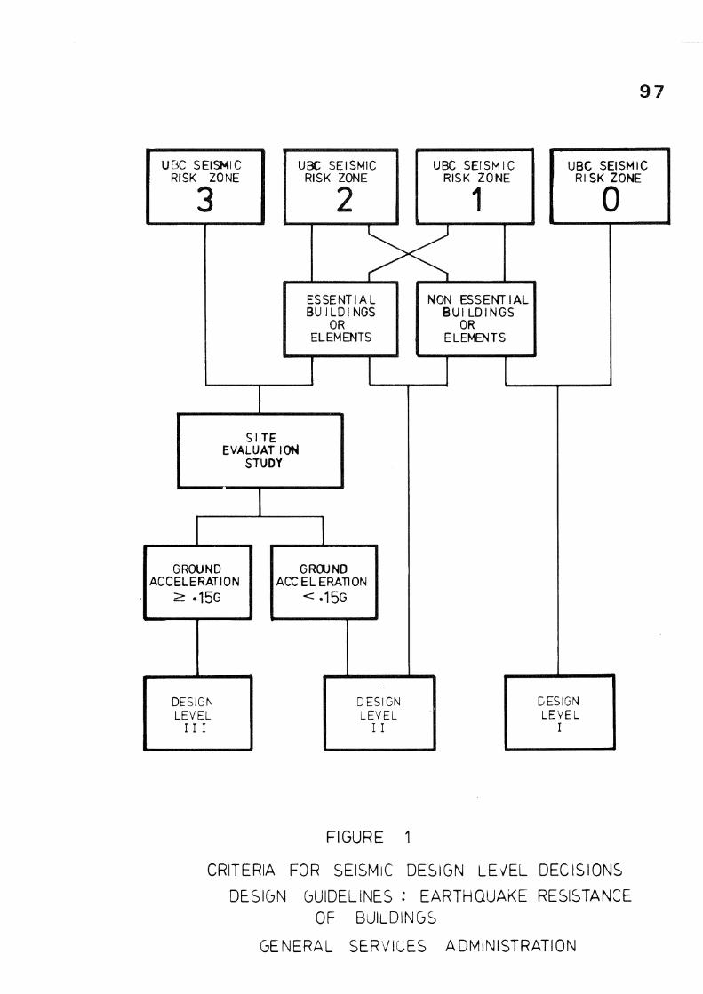
These guidelines, published in 1976, set out the requirements for public buildings in the U.S. administered by the GSA. The calculation is based on a three level approach (Fig. 1 ) ,
The method used is based on UBC and Tri Services with some information from VA and Title 17. This code uses seismic zones as set out in UBC except that it recommends that designs in Zone 0 (lowest risk) should be able to resist 0.03 g - 0.05 g acceleration. It is suggested that where insufficient information is given a C p value should be determined using the method in the Tri Services Manual. The lateral force is determined from
z c w P1 p
Z = Zone factor based on the estimated peak ground acceleration.
C = Seismic force factor. Tabulated values P are given for each level of resistant
design and ground acceleration. Tabulated values are increased by 50% for the upper levels of tall buildings and it is recommended that flexible equipment in the upper storeys of buildings with a predominant period close to that of the building should have a magnification factor of two.
Further recommendations cover the location of emergency equipment. Site evaluation is recommended for all buildings in Zone 3 and essential buildings in Zone 2. Further general details and do and don't statements are included along with an explanatory commentary.
(f) National Fire Protection Association Code, National Fire Code Vol. 13 installation of Sprinkler Systems" (NFPA) (8T
This code has included seismic bracing
(h) Tentative Provisions for the Development of Seismic Regulations for Buildings (ATC-3) (10)
This recent comprehensive document is the combined effort of many professionals and introduces a number of concepts not included in other current codes. It states the recommended provisions and includes an explanatory commentary. It uses the concept of seismic hazard groups for different classes of building, a component rating and a zoning factor based on a seismic derived effective peak velocity related acceleration (A v). The code discusses the inter-relationship of architectural, structural, mechanical and electrical components but refrains from including detailed advice on how this should be used.
Seismically induced forces are determined from
F = A C P a a W p v c c x c
where
F = Seismic force applied to a component of P a building or equipment at its centre
of gravity.
v Seismic coefficient representing the effective peak velocity related acceleration. Range 0.05 to 0.40. Performance criteria factor, three clauses are used, superior 1.5, good 1.0, low 0.5. Each tabulated items is given a rating for each seismic hazard exposure group which roughly translates to the building class used in NZS 4203. By this means it is possible to assign different ratings to both the ability of the equipment to withstand seismic forces as well as the importance of its application. Tabulated coefficient, range 0.67 or 2.00
9 7
UBC SEISMIC RISK ZONE
UBC SEISMIC RISK ZONE
ESSENTIAL BUILDINGS
OR ELEMENTS
UBC SEISMIC RISK ZONE
1
NON ESSENT BUI LDING
OR ELEMENTS
IAL -S
UBC SEISMIC RISK ZONE
0
S I T E EVALUAT I OH
STUDY
GROUND ACCELERATION
> -15G
GROUND ACCELERATION
<-15G
DESIGN LEVEL
I I I
DESIGN LEVEL
I I
DESIGN LEVEL
I
FIGURE 1
CRITERIA FOR SEISMIC DESIGN LEv'EL DECISIONS
DESIGN GUIDELINES : EARTHQUAKE RESISTANCE OF BUILDINGS
GENERAL SERVICES ADMINISTRATION
98
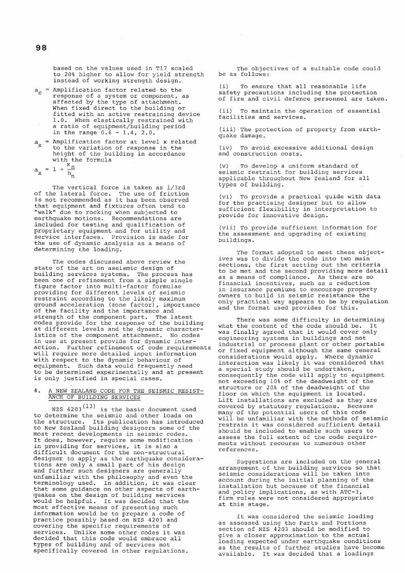
based on the values used in T17 scaled to 20% higher to allow for yield strength instead of working strength design.
a c = Amplification factor related to the response of a system or component, as affected by the type of attachment. When fixed direct to the building or fitted with an active restraining device 1.0. When elastically restrained with a ratio of equipment/building period in the range 0.6 - 1.4, 2.0.
a = Amplification factor at level x related x to the variation of response in the
height of the building in accordance with the formula
The vertical force is taken as l/3rd of the lateral force. The use of friction is not recommended as it has been observed that equipment and fixtures often tend to "walk" due to rocking when subjected to earthquake motions. Recommendations are included for testing and qualification of proprietary equipment and for utility and service interfaces. Provision is made for the use of dynamic analysis as a means of determining the loading.
The codes discussed above review the state of the art on aseismic design of building services systems. The process has been one of refinement from a simple single figure factor into multi-factor formulae providing for different levels of seismic restraint according to the likely maximum ground acceleration (zone factor), importance of the facility and the importance and strength of the component part. The latest codes provide for the response of the building at different levels and the dynamic characteristics of the component attachment. No codes in use at present provide for dynamic interaction. Further refinement of code requirements will require more detailed input information with respect to the dynamic behaviour of equipment. Such data would frequently need to be determined experimentally and at present is only justified in special cases.
4. A NEW ZEALAND CODE FOR THE SEISMIC RESISTANCE OF BUILDING SERVICES
(13) NZS 42 03 is the basic document used
to determine the seismic and other loads on the structure. Its publication has introduced to New Zealand building designers some of the most recent developments in seismic codes. It does, however, require some modification • in providing for services, it is also a difficult document for the non-structural designer to apply as the earthquake considerations are only a small part of his design and further such designers are generally unfamiliar with the philosophy and even the terminology used. In addition, it was clear that some guidance on other aspects of earthquakes on the design of building services would be helpful. It was decided that the most effective means of presenting such information would be to prepare a code of practice possibly based on NZS 4203 and covering the specific requirements of services. Unlike some other codes it was decided that this code would embrace all types of building and of services not specifically covered in other regulations.
The objectives of a suitable code could be as follows:
(i) To ensure that all reasonable life safety precautions including the protection of fire and civil defence personnel are taken.
(ii) To maintain the operation of essential facilities and services.
(iii) The protection of property from earthquake damage.
(iv) To avoid excessive additional design and construction costs.
(v) To develop a uniform standard of seismic restraint for building services applicable throughout New Zealand for all types of building.
(vi) To provide a practical guide with data for the practising designer but to allow sufficient flexibility in interpretation to provide for innovative design.
(vii) To provide sufficient information for the assessment and upgrading of existing buildings.
The format adopted to meet these objectives was to divide the code into two main sections, the first setting out the criteria to be met and the second providing more detail as a means of compliance. As there are no financial incentives, such as a reduction in insurance premiums to encourage property owners to build in seismic resistance the only practical way appears to be by regulation and the format used provides for this.
There was some difficulty in determining what the content of the code should be. It was finally agreed that it would cover only engineering systems in buildings and not industrial or process plant or other portable or fixed equipment although the same general considerations would apply. Where dynamic interaction was likely it was considered that a special study should be undertaken, consequently the code will apply to equipment not exceeding 10% of the deadweight of the structure or 2 0% of the deadweight of the floor on which the equipment is located. Lift installations are excluded as they are covered by statutory regulations. Because many of the potential users of this code will be unfamiliar with the methods of seismic restrain it was considered sufficient detail should be included to enable such users to assess the full extent of the code requirements without recourse to numerous other references.
Suggestions are included on the general arrangement of the building services so that seismic considerations will be taken into account during the initial planning of the installation but because of the financial and policy implications, as with ATC-3, firm rules were not considered appropriate at this stage.
It was considered the seismic loading as assessed using the Parts and Portions section of NZS 4203 should be modified to give a closer approximation to the actual loading expected under earthquake conditions as the results of further studies have become available. It was decided that a loadings
9 9
clause should be included which would generally follow the suggested procedure set out in a report by Kellyt 1 1^ with the alternative of a dynamic analysis at the option of the designer. Information to enable the designer to assess the building deformation is included so that allowance could be made for the deflection where services or equipment were fixed to different structural elements such as between two floors or where the services pass over a seismic break. To enable the design of fixings and supports basic information on geometrical properties for elastic and plastic design are included. The requirement is generally to conform with NZS 3404 : 1977 ^ ' and abbreviated details are included in the Means of Compliance Section. Allowable stresses for the more common materials and components are also included again to reduce the design effort and assist in checking.
Most building services equipment consists of lightweight packages and interconnecting pipes, ducts or cables. The building services designer will seldom have influence over the constructional details and strength of such proprietary equipment (much of which will not be selected until after construction has commenced), however he will have some control over the fixing details, of which sufficient data is included for selection.
Mechanical equipment, flexibly mounted and over 50 kg mass, must be positively restrained?while such equipment less than 50 kg may use captive type mounts. Although such equipment could be subject to resonant vibration, it is unlikely to cause much damage if it breaks free. It was considered that 50 kg would be a reasonable level at which the transition to a more secure fixing should be used. Falling suspended equipment in occupied spaces is a life hazard and is likely to cause panic; such equipment must be positively fixed and cannot be left freely suspended by the ceiling system or similar support. Positive fixing is required for luminaires and air handling fittings.
The damage to pipework is largely a function of relative flexibility. All parts of the one pipe should be attached to the one structural system or have the same degree of freedom to move in unison. Using seismic loading alone will not ensure that damage will not result; rules are given for the bracing of pipework, these are largely based on the current practice in the American codes reviewed above.
Most buildings could not be occupied for a prolonged period without a water supply. Consideration was given to the possibility of providing for this in Class I and some Class II buildings but the implications of this indicated that it was a matter of policy by the building owners or operators. As most of these buildings are public buildings it was decided to draw attention to the problem without setting out specific requirements.
Difference in opinion exists with the use of automatic gas shut off valves as there is always a risk that when the supply is restored there may be open taps which could cause an accumulation of gas and
and result in an explosion and due to the considerable inconvenience resulting when finely set valves operate unnecessarily resulting in the shut off valve eventually being fixed in the open position. It was decided that for larger installations using more than 50 m /hour seismically operated valves should be fitted as such installations would normally consist of large appliances or would have a responsible person on hand to reset the valve.
This review has dealt with a few of the requirements covered by the code; special provisions for most of the common services are also covered with specific clauses.
5. CONCLUSIONS
(i) Investigation has shown that nonstructural damage can be a large proportion of the cost particuarly in moderate earthquakes. This has created a greater awareness of the need to provide protection.
(ii) The damage to building services can be reduced by careful building design.
(iii) The equivalent static force analysis is suitable for most installations. The more comprehensive dynamic studies are only required in special cases.
(iv) Equipment must be properly anchored. The effect of earthquake forces on internal components may need to be considered with some equipment.
(v) A higher standard of protection should be used for life safety services.
(vi) Building services designers are generally unfamiliar with the detailed requirements for earthquake fixings. By including basic data in the code of practice it will assist in obtaining a standard of seismic resistance comparable with that already used for structures.
(vii) Well engineered installations will only result from an awareness of the nature of the problem and its solutions by building designers, constructors, owners and users working as a co-operative team.
(viii) There is a need for the further development of standards for proprietary equipment. Many codes are largely concerned with fixings only.
(ix) Physical testing of systems and packages would help to determine more appropriate coefficients and identify weaknesses. Standard procedures for seismic qualification testing need to be developed.
(x) Design guides and manuals similar to the SMACNA Code need to be developed to reduce design costs and develop uniform trade procedures.
(xi) Most testing and detailed analytical studies have been carried out in nuclear power, electricity generation and communication industries. Some of this work has potential application in building services. ACKNOWLEDGEMENTS
The Code for the Seismic Resistance of
1 0 0
Building Services is the combined effort of a SANZ Committee, whose contribution to this paper is gratefully acknowledged. The permission of the Commissioner of Works, Ministry of Works and Development, to present this paper is acknowledged.
REFERENCES
1. Ayres, J. M., Sun, T. Y., and Brown, F. R., "Non-Structural Damage to Buildings", The Great Alaska Earthquake of 1964 : National Academy of Sciences, Washington D.C. 1973.
2. Ayres, J. M., Sun, T. Y., "Non-Structural Damage" San Fernando, California, Earthquake of February 9, 1971. National Oceanic and Atmospheric Administration, U.S. Department of Commerce, Washington D.C. 197 3 Volume I.
3. "Seismic Design for Buildings", U.S. Departments of the Army, the Navy and the Air Force, Technical Manual No. 5-809-10 (April 1973).
4. "Uniform Building Code" 1976 Ed., International Conference of Building Officials* Whittier, California.
5. "Safety of Construction of Hospitals" Title 17, California, Admin., Code T17-2314, 1973.
6. "Earthquake Resistant Design Requirements for VA Hospital Facilities", Handbook H-08-8 Office of Construction, Veterans Administration 1973 and 1974 Amendment.
7 . "Design Guidelines, Earthquake Resistance of Buildings", General Services Administration, Public Buildings Service 1976.
8. Sections 3150-3169 National Fire Protection Association, Standard 13, Boston, Massachusetts.
9. "Guidelines for Seismic Restraints of Mechanical Systems", Sheet Metal and Air Conditioning Contractors National Association, Inc., Sheet Metal Industry Fund of Los Angeles, First Edition 1976.
10. "Tentative Provisions for the Development of Seismic Regulations for Buildings", Applied Technology Council ATC Publication ATC 3-06, June 1978.
11. "Floor Response of Yielding Structures", T. E. Kelly Research and Development Report 78/1, September 1978, Office of Chief Structural Engineer, Ministry of Works and Development, Wellington.
12. Code for Design of Steel Structures (with commentary) NZS 3404 : 1977 Standards Association of New Zealand.
13. NZS 4203 : 1976 Code of Practice for General Structural Design and Design Loadings for Buildings, Standards Association of New Zealand.
This paper was presented at the South Pacific Regional Conference on Earthquake Engineering held in Wellington on 8, 9 and 10 May, 1979.
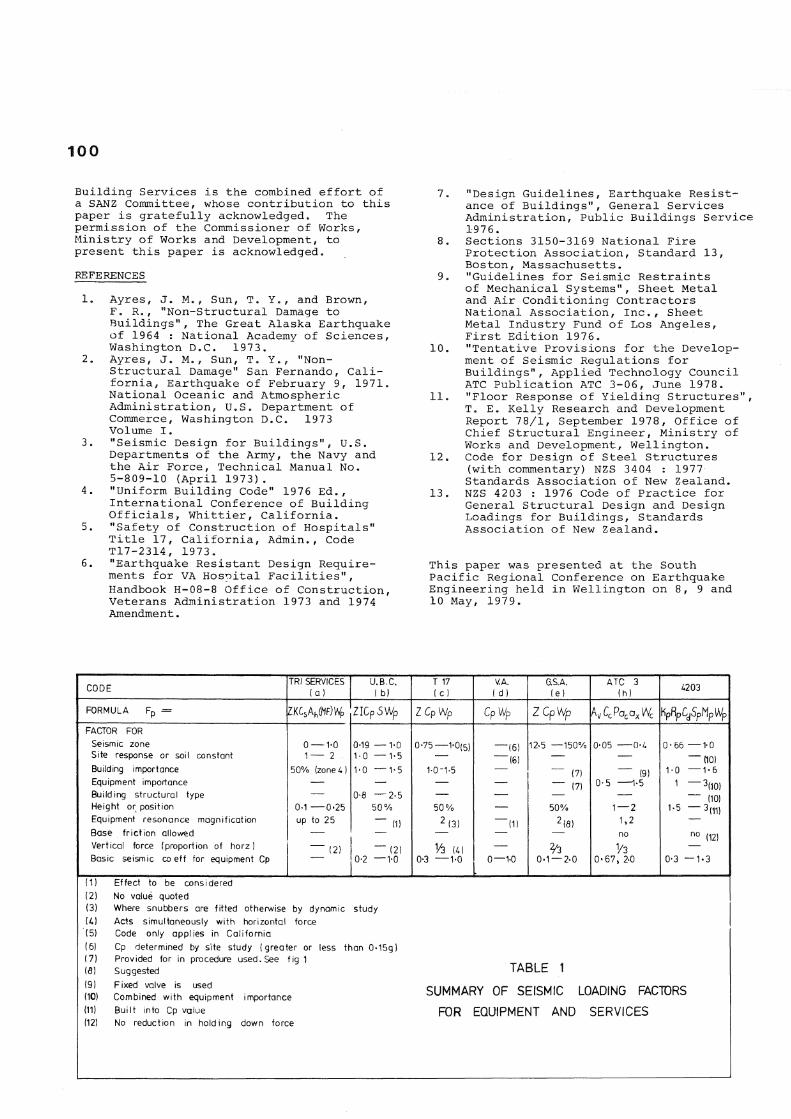
CODE TRI SERVICES (a )
U.B.C. ( b}
T 17 ( c ]
V.A. ( d)
G.S.A. (e)
ATC 3 (h) £203
FORMULA F p = ZKCsAh(HF)V/p
FACTOR FOR Seismic zone Site response or soil constant Building importance Equipment importance Building structural type Height or position Equipment resonance magnification Base friction allowed Vertical force (proportion of horz) Basic seismic co eff for equipment Cp
0 —1-0 1 — 2
50% (zone 4)
0-1 0'25 up to 25
(2)
ZIGpSWp ZCpWp CpWp ZCpWp AvCcPacaxWc HpRpC SpMpiVp
0-19 —1-0 1-0 — V 5 1-0 —1-5
0-8 —2-5 50%
~ " (2) 0-2 —1-0
0-75—1-0(5)
1-0-1-5
50% 2 (3)
0-3 —1-0
"(6) "(6)
(1)
-1-0
12-5 —150%
~~ (7) — (7)
50% 2 (8)
% 0-1 —2-0
0-05 0-4
(9) 0-5 1*5
1—2 1,2 no
1/3 0*67, 2-0
0-66 —1-0 — (10)
1-0 1
-1-6 -*(10)
— (10) 1-5 — 3 ( 1 1 )
no ( 1 2 )
0-3 —1-3
(1} Effect to be considered (2) No value quoted (3) Where snubbers are fitted otherwise by dynamic study U l Acts simultaneously with horizontal force (5) Code only applies in California (6} Cp determined by site study (greater or less than 0»15g) (7) Provided for in procedure used. See fig 1 (8) Suggested (9) Fixed valve is used (10) Combined with equipment importance (11) Built into Cp value (12) No reduction in holding down force
TABLE 1
SUMMARY OF SEISMIC LOADING FACTORS FOR EQUIPMENT AND SERVICES