a delta-sigma beamformer with integrated apodization -...
TRANSCRIPT
General rights Copyright and moral rights for the publications made accessible in the public portal are retained by the authors and/or other copyright owners and it is a condition of accessing publications that users recognise and abide by the legal requirements associated with these rights.
• Users may download and print one copy of any publication from the public portal for the purpose of private study or research. • You may not further distribute the material or use it for any profit-making activity or commercial gain • You may freely distribute the URL identifying the publication in the public portal
If you believe that this document breaches copyright please contact us providing details, and we will remove access to the work immediately and investigate your claim.
Downloaded from orbit.dtu.dk on: Jun 13, 2018
A Delta-Sigma beamformer with integrated apodization
Tomov, Borislav Gueorguiev; Stuart, Matthias Bo; Hemmsen, Martin Christian; Jensen, Jørgen Arendt
Published in:Proceedings of SPIE
Link to article, DOI:10.1117/12.2006731
Publication date:2013
Link back to DTU Orbit
Citation (APA):Tomov, B. G., Stuart, M. B., Hemmsen, M. C., & Jensen, J. A. (2013). A Delta-Sigma beamformer withintegrated apodization. In Proceedings of SPIE: Medical Imaging 2013: Ultrasonic Imaging, Tomography, andTherapy SPIE - International Society for Optical Engineering. DOI: 10.1117/12.2006731

A Delta-Sigma beamformer with integrated apodization
Borislav Gueorguiev Tomov, Matthias Bo Stuart, Martin Christian Hemmsen,Jørgen Arendt Jensen
Center for Fast Ultrasound Imaging, Technical University of Denmark, 2800 Lyngby, Denmark
ABSTRACT
This paper presents a new design of a discrete time Delta-Sigma (∆Σ) oversampled ultrasound beamformerwhich integrates individual channel apodization by means of variable feedback voltage in the Delta-Sigma analogto digital (A/D) converters. The output bit-width of each oversampled A/D converter remains the same as inan unmodified one. The outputs of all receiving channels are delayed and summed, and the resulting multi-bitsample stream is filtered and decimated to become an image line. The simplicity of this beamformer allowsthe production of high-channel-count or very compact beamformers suitable for 2-D arrays or compact portablescanners. The new design is evaluated using measured data from the research scanner SARUS and a BK-8811192 element linear array transducer (BK Medical, Herlev, Denmark), insonifying a water-filled wire phantomcontaining four wires orthogonal to the image plane. The data are acquired using 12-bit flash A/D convertersat a sampling rate of 70 MHz, and are then upsampled off-line to 560 MHz for input to the simulated ∆Σbeamformer. The latter generates a B-mode image which is compared to that produced by a digital beamformerthat uses 10-bit A/D converters. The performance is evaluated by comparing the width of the wire images athalf amplitude and the noise level of the images. The ∆Σ beamformer resolution has been found to be identicalto that of the multi-bit A/D beamforming architecture, while the noise floor is elevated by approximately 6 dB.
Keywords: Ultrasound imaging, Delta Sigma converter, beamforming
1. INTRODUCTION
Multi-bit Nyquist-rate analog-to-digital (A/D) converters are the core building blocks of modern digital ultra-sound beamformers. Using Nyquist-rate A/D converters, significant effort has to be put into signal precondition-ing and the generation of both voltage and time references. Oversampling A/D converters trade digital signalprocessing complexity for relaxed requirements on the analog components compared to Nyquist-rate A/D con-verters. The Delta-Sigma modulation (DSM) A/D converter combines both oversampling and noise shaping, andmakes it possible to effectively convert an electrical analog signal into its digital, discrete-time representationusing modern digital CMOS technology.1–3 The use of such converters in ultrasound beamformers offers thefollowing advantages: integration of beamforming logic and A/D converters, as these can be manufactured usingthe same semiconductor technology; small area per converter, allowing to accommodate a large number of A/Dconverters on a single chip; and low price.
Direct use of DSM A/D converters, followed by first-in-first-out (FIFO) fixed-length delay buffers, adderand filter/decimator results in a simple fixed focus beamformer with great scalability. Unfortunately, such abeamformer lacks two features necessary for high quality imaging: weighting/apodization of the received signals,and dynamic adjustment of the relative delays between the channel data for the purpose of maintaining a shiftingreceive focus that follows the current reconstructed echo sample.
A number of researchers have worked on incorporating dynamic receive focusing in ∆Σ beamformers.4–6 Thesolutions have suffered to various degrees from introducing extra noise into the digitized signal and/or requiringadditional digital logic. The need for dynamic receive focusing can be overcome by utilizing sequential syntheticaperture beamforming,7 where the first beamforming stage is a fixed-focus beamformer. With that applicationin mind, the current paper presents a comparison of fixed-focus beamformers.
Send correspondence to Borislav Gueorguiev Tomov: E-mail: [email protected], Telephone: +45 45 25 39 01
The problem of integrating channel apodization into such a beamformer has persisted until now. The obviousapproach of using coefficient registers on each channel, selectable by the ADC output bit value (in a case of a bi-level quantizer), requires a large number of multi-bit adders, which counteracts the goal of simplicity/scalabilityof the beamformer.
Variable ∆Σ modulator feedback has been investigated by Norman8 for the purpose of implementing timegain compensation inside an oversampled converter. In that work, apodization across the channels was notconsidered.
This paper presents a new design of a discrete time Delta-Sigma (∆Σ) oversampled ultrasound beamformerwhich integrates individual channel apodization by means of variable feedback voltage in the Delta-Sigma analogto digital (A/D) converters. The output bit-width of each oversampled A/D converter remains the same as inan unmodified one. The outputs of all receiving channels are delayed and summed, and the resulting multi-bitsample stream is filtered and decimated to become an image line. The involved signal processing principlesare presented in Section 2. A comparison of the obtained image to one made using a 10-bit A/D based digitalbeamformer has been made, and the results are presented in Section 3. The discussion of the suggested newarchitecture is presented in Section 4, followed by conclusion in Section 5.
2. METHODS
This section introduces ∆Σ modulators with variable feedback gain and illustrates their use in a beamformerarchitecture that features channel weighting (apodization).
2.1 Delta-Sigma modulation
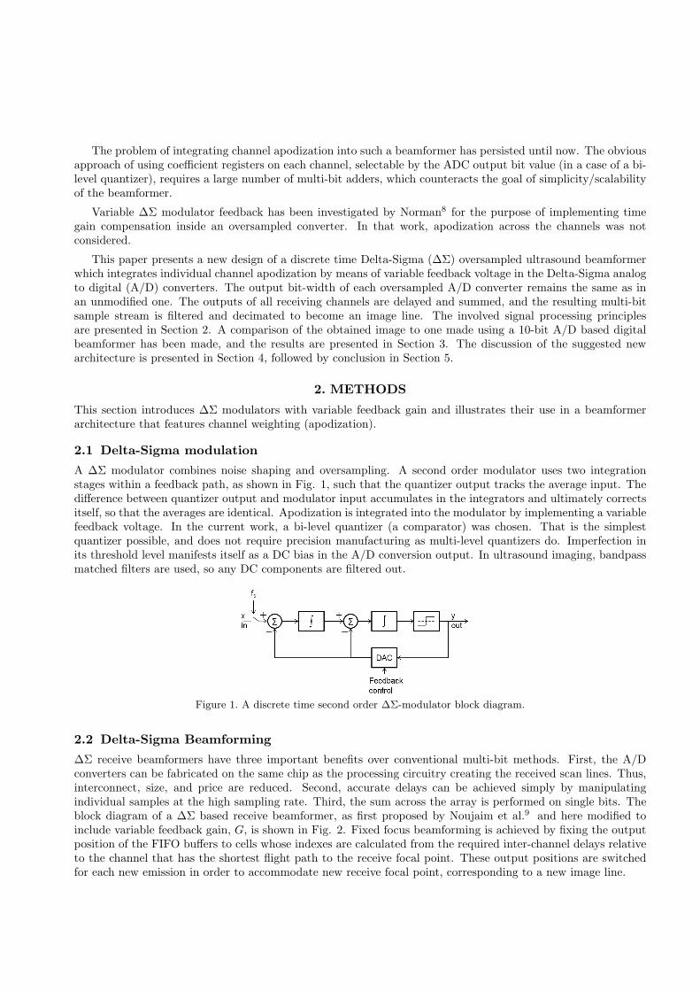
A ∆Σ modulator combines noise shaping and oversampling. A second order modulator uses two integrationstages within a feedback path, as shown in Fig. 1, such that the quantizer output tracks the average input. Thedifference between quantizer output and modulator input accumulates in the integrators and ultimately correctsitself, so that the averages are identical. Apodization is integrated into the modulator by implementing a variablefeedback voltage. In the current work, a bi-level quantizer (a comparator) was chosen. That is the simplestquantizer possible, and does not require precision manufacturing as multi-level quantizers do. Imperfection inits threshold level manifests itself as a DC bias in the A/D conversion output. In ultrasound imaging, bandpassmatched filters are used, so any DC components are filtered out.
Figure 1. A discrete time second order ∆Σ-modulator block diagram.
2.2 Delta-Sigma Beamforming
∆Σ receive beamformers have three important benefits over conventional multi-bit methods. First, the A/Dconverters can be fabricated on the same chip as the processing circuitry creating the received scan lines. Thus,interconnect, size, and price are reduced. Second, accurate delays can be achieved simply by manipulatingindividual samples at the high sampling rate. Third, the sum across the array is performed on single bits. Theblock diagram of a ∆Σ based receive beamformer, as first proposed by Noujaim et al.9 and here modified toinclude variable feedback gain, G, is shown in Fig. 2. Fixed focus beamforming is achieved by fixing the outputposition of the FIFO buffers to cells whose indexes are calculated from the required inter-channel delays relativeto the channel that has the shortest flight path to the receive focal point. These output positions are switchedfor each new emission in order to accommodate new receive focal point, corresponding to a new image line.

Figure 2. ∆Σ beamforming architecture implementing variable feedback gain for each individual receiving channel.
2.3 Oversampling ratio calculation
The following calculations are based on the assumptions that the individual channel noise components are notcorrelated between channels, the spectrum density of the analog noise is constant across the spectrum (at theinput of the ADC), and the signal is a sinusoidal one.
The theoretical signal-to-noise ratio (SNR) of a multi-bit Nyquist-rate A/D converter is calculated (equation(11.16) in10) as
SNR = 6.02×N + 1.76 dB, (1)
where N is the number of output bits of the A/D converter, and the possible levels to represent the input are2N .
A 10-bit A/D converter, thus, achieves a SNR of
SNR = 6.02× 10 + 1.76 = 62 dB. (2)
The theoretical signal-to-noise ratio (SNR) of a second-order ∆Σ A/D converter is calculated (equation(14.32) in10) as
SNR = 6.02×N + 1.76− 12.9 + 50 logfs2f0
dB, (3)
where fs is the sampling rate and f0 is the frequency of the signal of interest. The fraction in the brackets iscalled oversampling ratio (OSR).
To achieve the 10-bit A/D converter SNR, a second-order ∆Σ A/D converter needs to operate at an over-sampling ratio (after transforming Eqn. 3) of
OSR = 1062−6.02−1.76+12.9
50 ≈ 22 (4)
An ultrasound beamformer creates image lines by focusing in different directions by means of applying delaysto the signals from individual elements, which are then summed. In doing that, the noise components in theinput signals are also summed. Assuming uncorrelated noise components with root-mean-square (RMS) valuesof Vi, the sum noise component will have an RMS value (by extending equation (4.14) in10) of

Vsum =
√√√√ 64∑i=1
V 2i (5)
As the echo data is summed across channels in an ultrasound beamformer, apodization is applied in orderto reduce edge effects and improve the sidelobe level of the imaging system point spread functions. When doingthat, the sampled noise (analog + quantization) components Vi in the individual channels do not add with equalamplitudes, but with scaled ones: Vi = ciVn, where where ci are the windowing function coefficients. For thecase of apodization using the Hamming windowing function, applied to 64 signals, the noise amplitude increasecan be calculated as
Vn64
Vn=
√√√√ 64∑i=1
c2i = 5, (6)
The increase of amplitude of the useful signal, assuming it has identical amplitude Vs on all channels beforethe apodization, is
Vs64
Vs=
64∑i=1
ci = 34.1, (7)
therefore the increase in SNR is 34.1/5 = 6.82 times, equivalent to 6 × log26.82 = 16.6 dB. The resulting SNRafter the channel signals sum is 62 + 16.6 = 78.6 dB.
Using the built-in apodization capability in the oversampled converters, the noise components (analog +quantization) in their output will have the same amplitudes and the summed noise component will grow by
Vn64o
Vno=
√√√√ 64∑i=1
12 = 8, (8)
The signal of interest will grow in the same way as in a multi-bit architecture (eqn. (7)). Thus, for 64channels, the SNR improvement will be 6 log2
34.18 = 12.6 dB, and matching the SNR performance of the 10-bit
A/D beamformer will require an oversampling ratio of
OSR = 1062+16.6−12.6−6.02−1.76+12.9
50 = 26.4, (9)
which, for a 7 MHz center frequency of the signal and assumed 100 % bandwidth, results in a required samplingfrequency for the Delta-Sigma modulators of 7× 1.5× 2× 26.4 = 554 MHz.
3. MEASUREMENT RESULTS
Raw radio frequency element data from a phantom containing four wires orthogonal to the imaging plane wasacquired using the SARUS research scanner,11,12 and a linear array transducer (BK-8811, BK Medical, Herlev,Denmark). For generating the B-mode images, the scanner was set up to acquire 192 scan lines with a transmitfocus set at a depth of 4 cm, using 64 active transmit elements weighted by a Hamming window function. Theexcitation was a two-cycle sinusoid with f0 = 7 MHz. The receive beamforming was done using the same fixeddelay profile as in transmit, using the same elements and apodization function.
Data was acquired at a sampling rate of 70 MHz, using 12-bit flash A/D converters. For use as an input tothe ∆Σ beamformer, the measured data was offline upsampled to 560 MHz (8 times upsampling). The combineddecimation/matched filter was created by convolving the excitation to the impulse response of the transducertwice, and upsampling the result to the modulation frequency. The impulse response was assumed to be that ofan ideal transducer (no tail/ringing) with 60 % bandwidth around 7 MHz. The resulting FIR filter was quantized

Wire index Depth Lat. width MB Lat. width OS Ax. width MB Ax. width OS1 33 1.04 1.04 0.49 0.492 56 3.64 3.64 0.42 0.423 79 5.98 5.98 0.44 0.434 104 6.76 6.76 0.46 0.46
Table 1. Depth of phantom wires, and lateral and axial widths of the wire images in the multi-bit A/D beamformed (MB)and oversampled A/D beamformed (OS) images. All units are in mm.
to 10-bit representation and has length of 401 coefficients. The feedback level of the ∆Σ A/D converter wasquantized to 16 levels (4-bit quantization) and the apodization in the multi-bit A/D beamformer was quantizedto 256 levels (10-bit representation).
Fig. 3 shows the generated B-mode images by a conventional multi-bit beamformer and the ∆Σ beamformer,with 70 dB dynamic range. Fig. 4 shows the lateral and axial profiles of the wire images. Fig. 4 shows the lateraland axial profiles of the imaged wires. The widths of the wire images measured at -6 dB in lateral and axialdirection are presented in Table 3. As expected, the wires further away for the focal point have wider profiles.
As can be observed, there exists an interference pattern that has entered the sampled data. The noise levelof the images under comparison was estimated by calculating the RMS value of the noise in an area that wasrelatively free of that pattern, at depths between 106 and 145 mm and lateral positions between -24.8 and -13.9mm. These values were then divided by the maximum signal values in the images, which in both cases are theclipped waveforms that represent the emitted signal. The estimated noise floor for the oversampled beamformerimage was -64.7 dB below maximum amplitude, and for the multi-bit beamformer it was at -70.4 dB belowmaximum amplitude.
4. DISCUSSION
The two images exhibit the same resolution, therefore introducing apodization in the oversampled architecturehas made its output indistinguishable from that of a multi-bit beamformer. The remaining drawback is theelevation of the noise floor, which is most likely due to non-optimal filtration for the purpose of removing thequantization noise.
5. CONCLUSION
A new ∆Σ beamforming architecture with integrated apodization in the discrete time ∆Σ modulator has beenpresented. The ∆Σ modulator implements apodization through variable feedback voltage. Using measureddata and offline processing, it was shown that the ∆Σ beamformer focusing performance matches that of aconventional multi-bit beamforming architecture using 10-bit parallel A/D converters, while the noise floor iselevated by about 6 dB.
The presented architecture in this paper is expected to contribute to the further development of compactanalog front-ends for multi channel scanners with very large channel count.
Acknowledgments
The presented work was financially supported by grant 024-2008-3 from the Danish Advanced Technology Foun-dation and by B-K Medical ApS, Denmark.
REFERENCES
[1] Inose, H., Yasuda, Y., and Murakami, J., “A telemetering system by code modulation - ∆Σ-modulation,”Space Electronics and Telemetry IRE Transactions on SET-8(3), 204–209 (1962).
[2] Candy, J. C. and Temes, G. C., [Oversampling Delta-Sigma Data Converters - Theory, Design and Simula-tion ], IEEE Press (1992).
[3] Norsworthy, S. R., Shreier, R., and Temes, G. C., [Delta-Sigma Data Converters : Theory, design andsimulation ], Wiley-IEEE Press (1996).

Oversampled BF
Lateral pos. [mm]
Dep
th [m
m]
−20 0 20
20
40
60
80
100
120
140
Multi−bit BF
Lateral pos. [mm]−20 0 20
20
40
60
80
100
120
140
Figure 3. B-mode images generated using an oversampled beamformer (left) and a conventional beamformer (right),displayed with 70 dB dynamic range.
[4] Freeman, S. R., Quick, M. K., Morin, M. A., Anderson, R. C., Desilets, C. S., Linnenbrink, T. E., andO’Donnell, M., “Delta-sigma oversampled ultrasound beamformer with dynamic delays,” IEEE Trans. Ul-trason., Ferroelec., Freq. Contr. 46, 320–332 (1999).
[5] Kozak, M. and Karaman, M., “Digital phased array beamforming using single-bit delta-sigma conversionwith non-uniform oversampling,” IEEE Trans. Ultrason., Ferroelec., Freq. Contr. 48, 922–931 (2001).
[6] Tomov, B. and Jensen, J. A., “Compact FPGA-based beamformer using oversampled 1-bit A/D converters,”IEEE Trans. Ultrason., Ferroelec., Freq. Contr. 52(5), 870–880 (2005).
[7] Kortbek, J., Jensen, J. A., and Gammelmark, K. L., “Sequential beamforming synthetic aperture imaging,”Ultrasonics 53(1) (2013).
[8] Norman, O., “A band-pass delta-sigma modulator for ultrasound imaging at 160 MHz clock rate,” IEEE J.Solid-State Circuits 31, 2036–2041 (1996).
[9] Noujaim, S. E., Garverick, S. L., and O’Donnel, M., “Phased array ultrasonic beam forming using oversam-pled A/D converters.” US Patent 5203335 (1993).
[10] Johns, D. and Martin, K., [Analog integrated circuit design ], John Wiley & Sons, Inc (1997).
[11] Jensen, J. A., Hansen, M., Tomov, B. G., Nikolov, S. I., and Holten-Lund, H., “System architecture of anexperimental synthetic aperture real time ultrasound system,” in [Proc. IEEE Ultrason. Symp. ], 636–640(Oct. 2007).

−10 −5 0 5 10
−50
−40
−30
−20
−10
Rel
. env
. lev
el, [
dB]
32 33 34 35
−50
−40
−30
−20
−10
−10 −5 0 5 10
−50
−40
−30
−20
−10
Rel
. env
. lev
el, [
dB]
55 56 57 58
−50
−40
−30
−20
−10
−10 −5 0 5 10
−50
−40
−30
−20
−10
Rel
. env
. lev
el, [
dB]
78.5 79 79.5 80 80.5 81
−50
−40
−30
−20
−10
−10 −5 0 5 10
−45
−40
−35
−30
−25
Lateral position, [mm]
Rel
. env
. lev
el, [
dB]
104 104.5 105 105.5 106 106.5
−50
−40
−30
Depth, [mm]
Figure 4. Lateral (left) and axial (right) profiles of the four image wires. The oversampled beamformer envelopes areshown in gray, and the multi-bit beamformer envelopes are shown with dash-dotted black line.
[12] Jensen, J. A., Holten-Lund, H., Nielson, R. T., Tomov, B. G., Stuart, M. B., Nikolov, S. I., Hansen, M.,and Larsen, U. D., “Performance of SARUS: A Synthetic Aperture Real-time Ultrasound System,” in [Proc.IEEE Ultrason. Symp. ], 305–309 (Oct. 2010).