a hybrid-statcom with wide compensation range and … hybrid... · he large reactive current in...
TRANSCRIPT

IEEE TRANSACTIONS ON INDUSTRIAL ELECTRONICS, VOL. 63, NO. 6, JUNE 2016 3333
A Hybrid-STATCOM With Wide CompensationRange and Low DC-Link Voltage
Lei Wang, Chi-Seng Lam, Senior Member, IEEE , and Man-Chung Wong, Senior Member, IEEE
Abstract—This paper proposes a hybrid staticsynchronous compensator (hybrid-STATCOM) in a three-phase power transmission system that has a widecompensation range and low dc-link voltage. Because ofthese prominent characteristics, the system costs can begreatly reduced. In this paper, the circuit configuration ofhybrid-STATCOM is introduced first. Its V–I characteristicis then analyzed, discussed, and compared with traditionalSTATCOM and capacitive-coupled STATCOM (C-STATCOM).The system parameter design is then proposed on thebasis of consideration of the reactive power compensationrange and avoidance of the potential resonance prob-lem. After that, a control strategy for hybrid-STATCOM isproposed to allow operation under different voltage andcurrent conditions, such as unbalanced current, voltagedip, and voltage fault. Finally, simulation and experimentalresults are provided to verify the wide compensationrange and low dc-link voltage characteristics and the gooddynamic performance of the proposed hybrid-STATCOM.
Index Terms—Capacitive-coupled static synchronouscompensator (C-STATCOM), hybrid-STATCOM, low dc-linkvoltage, STATCOM, wide compensation range.
I. INTRODUCTION
T HE LARGE reactive current in transmission systemsis one of the most common power problems, which
increases transmission losses and lowers the stability of a powersystem [1]–[19]. Application of reactive power compensators isone of the solutions for this issue.
Static Var compensators (SVCs) are traditionally used todynamically compensate reactive currents as the loads varyfrom time to time. However, SVCs suffer from many problems,such as resonance problems, harmonic current injection, andslow response [2], [3]. To overcome these disadvantages, staticsynchronous compensators (STATCOMs) and active power fil-ters (APFs) were developed for reactive current compensationwith faster response, less harmonic current injection, and better
Manuscript received June 13, 2015; revised October 2, 2015 andNovember 21, 2015; accepted December 23, 2015. Date of publicationFebruary 8, 2016; date of current version May 10, 2016. This work wassupported in part by the Macau Science and Technology DevelopmentFund (FDCT) (FDCT 109/2013/A3) and in part by the ResearchCommittee of the University of Macau (MRG012/WMC/2015/FST,MYRG2015-00030-AMSV) (Corresponding author: Chi-Seng Lam.)
L. Wang is with the Department of Electrical and ComputerEngineering, Faculty of Science and Technology, University of Macau,Macau 999078, China (e-mail: [email protected]).
C.-S. Lam and M.-C. Wong are with the Department of Electricaland Computer Engineering, Faculty of Science and Technology,and the State Key Laboratory of Analog and Mixed Signal VLSI,University of Macau, Macau 999078, China (e-mail: [email protected];[email protected]; [email protected]).
Color versions of one or more of the figures in this paper are availableonline at http://ieeexplore.ieee.org.
Digital Object Identifier 10.1109/TIE.2016.2523922
performance [4]–[9]. However, the STATCOMs or APFs usu-ally require multilevel structures in a medium- or high-voltagelevel transmission system to reduce the high-voltage stressacross each power switch and dc-link capacitor, which drivesup the initial and operational costs of the system and alsoincreases the control complexity. Later, series-type capacitive-coupled STATCOMs (C-STATCOMs) were proposed to reducethe system dc-link operating voltage requirement [10], andother series-type hybrid structures that consist of differentpassive power filters (PPFs) in series with STATCOMs orAPF structures (PPF-STATCOMs) have been applied to powerdistribution systems [11]–[16] and traction power systems[17]–[19]. However, C-STATCOMs and other series-type PPF-STATCOMs contain relatively narrow reactive power compen-sation ranges. When the required compensating reactive poweris outside their compensation ranges, their system performancescan significantly deteriorate.
To improve the operating performances of the traditionalSTATCOMs, C-STATCOMs, and other PPF-STATCOMs,many different control techniques have been proposed, suchas the instantaneous p–q theory [4], [10], [11], [17]–[19], theinstantaneous d–q theory [5], [6], [14], the instantaneous id–iqmethod [7], negative- and zero-sequence control [8], the backpropagation (BP) control method [9], nonlinear control [12],Lyapunov-function-based control [13], instantaneous symmet-rical component theory [15], and hybrid voltage and currentcontrol [16].
To reduce the current rating of the STATCOMs or APFs,a hybrid combination structure of PPF in parallel withSTATCOM (PPF//STATCOM) was proposed in [20] and [21].However, this hybrid compensator is dedicated for inductiveloading operation. When it is applied for capacitive loadingcompensation, it easily loses its small active inverter ratingcharacteristics. To enlarge the compensation range and keeplow current rating characteristic of the APF, Dixon et al. [22]proposed another hybrid combination structure of SVC in par-allel with APF (SVC//APF) in three-phase distribution systems.In this hybrid structure, the APF is controlled to eliminatethe harmonics and compensate for the small amounts of loadreactive and unbalanced power left by the SVC. However, ifthis structure is applied in a medium- or high-voltage-leveltransmission system, the APF still requires a costly voltagestep-down transformer and/or multilevel structure. In addi-tion, these two parallel connected-hybrid-STATCOM structures[15]–[17] may suffer from a resonance problem.
To overcome the shortcomings of different reactivepower compensators [1]–[22] for transmission systems, thispaper proposes a hybrid-STATCOM that consists of a
0278-0046 © 2016 IEEE. Personal use is permitted, but republication/redistribution requires IEEE permission.See http://www.ieee.org/publications_standards/publications/rights/index.html for more information.
3334 IEEE TRANSACTIONS ON INDUSTRIAL ELECTRONICS, VOL. 63, NO. 6, JUNE 2016
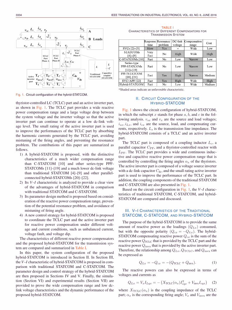
Fig. 1. Circuit configuration of the hybrid-STATCOM.
thyristor-controlled LC (TCLC) part and an active inverter part,as shown in Fig. 1. The TCLC part provides a wide reactivepower compensation range and a large voltage drop betweenthe system voltage and the inverter voltage so that the activeinverter part can continue to operate at a low dc-link volt-age level. The small rating of the active inverter part is usedto improve the performances of the TCLC part by absorbingthe harmonic currents generated by the TCLC part, avoidingmistuning of the firing angles, and preventing the resonanceproblem. The contributions of this paper are summarized asfollows.
1) A hybrid-STATCOM is proposed, with the distinctivecharacteristics of a much wider compensation rangethan C-STATCOM [10] and other series-type PPF-STATCOMs [11]–[19] and a much lower dc-link voltagethan traditional STATCOM [4]–[9] and other parallel-connected hybrid-STATCOMs [20]–[22].
2) Its V–I characteristic is analyzed to provide a clear viewof the advantages of hybrid-STATCOM in comparisonwith traditional STATCOM and C-STATCOM.
3) Its parameter design method is proposed based on consid-eration of the reactive power compensation range, preven-tion of the potential resonance problem, and avoidance ofmistuning of firing angle.
4) A new control strategy for hybrid-STATCOM is proposedto coordinate the TCLC part and the active inverter partfor reactive power compensation under different volt-age and current conditions, such as unbalanced current,voltage fault, and voltage dip.
The characteristics of different reactive power compensatorsand the proposed hybrid-STATCOM for the transmission sys-tem are compared and summarized in Table I.
In this paper, the system configuration of the proposedhybrid-STATCOM is introduced in Section II. In Section III,the V–I characteristic of hybrid-STATCOM is proposed in com-parison with traditional STATCOM and C-STATCOM. Theparameter design and control strategy of the hybrid-STATCOMare then proposed in Sections IV and V. Finally, the simula-tion (Section VI) and experimental results (Section VII) areprovided to prove the wide compensation range and low dc-link voltage characteristics and the dynamic performance of theproposed hybrid-STATCOM.
TABLE ICHARACTERISTICS OF DIFFERENT COMPENSATORS FOR
TRANSMISSION SYSTEM
*Shaded areas indicate an unfavorable characteristic.
II. CIRCUIT CONFIGURATION OF THE
HYBRID-STATCOM
Fig. 1 shows the circuit configuration of hybrid-STATCOM,in which the subscript x stands for phase a, b, and c in the fol-lowing analysis. vsx and vx are the source and load voltages;isx, iLx, and icx are the source, load, and compensating cur-rents, respectively. Ls is the transmission line impedance. Thehybrid-STATCOM consists of a TCLC and an active inverterpart.
The TCLC part is composed of a coupling inductor Lc, aparallel capacitor CPF, and a thyristor-controlled reactor withLPF. The TCLC part provides a wide and continuous induc-tive and capacitive reactive power compensation range that iscontrolled by controlling the firing angles αx of the thyristors.The active inverter part is composed of a voltage source inverterwith a dc-link capacitor Cdc, and the small rating active inverterpart is used to improve the performance of the TCLC part. Inaddition, the coupling components of the traditional STATCOMand C-STATCOM are also presented in Fig. 1.
Based on the circuit configuration in Fig. 1, the V–I charac-teristics of traditional STATCOM, C-STATCOM, and hybrid-STATCOM are compared and discussed.
III. V–I CHARACTERISTICS OF THE TRADITIONAL
STATCOM, C-STATCOM, AND HYBRID-STATCOM
The purpose of the hybrid-STATCOM is to provide the sameamount of reactive power as the loadings (QLx) consumed,but with the opposite polarity (Qcx = −QLx). The hybrid-STATCOM compensating reactive power Qcx is the sum of thereactive power QTCLC that is provided by the TCLC part and thereactive power Qinvx that is provided by the active inverter part.Therefore, the relationship among QLx, QTCLC, and Qinvx canbe expressed as
QLx = −Qcx = −(QTCLC +Qinvx). (1)
The reactive powers can also be expressed in terms ofvoltages and currents as
QLx = VxILqx = − (XTCLC(αx)I
2cqx + VinvxIcqx
)(2)
where XTCLC(αx) is the coupling impedance of the TCLCpart; αx is the corresponding firing angle; Vx and Vinvx are the

WANG et al.: HYBRID-STATCOM WITH WIDE COMPENSATION RANGE AND LOW DC-LINK VOLTAGE 3335
root-mean-squared (RMS) values of the coupling point and theinverter voltages; and ILqx and Icqx are the RMS value of theload and compensating reactive currents, where ILqx = −Icqx.Therefore, (2) can be further simplified as
Vinvx = Vx +XTCLC(αx)ILqx (3)
where the TCLC part impedance XTCLC(αx) can be expressedas
XTCLC(αx) =XTCR(αx)XCPF
XCPF −XTCR(αx)+XLc
=πXLPFXCPF
XCPF(2π − 2αx + sin 2αx)− πXLPF
+XLc
(4)
where XLc, XLPF
, and XCPFare the fundamental impedances
of Lc, LPF, and CPF, respectively. In (4), it is shown that theTCLC part impedance is controlled by firing angle αx. Andthe minimum inductive and capacitive impedances (absolutevalue) of the TCLC part can be obtained by substituting thefiring angles αx = 90◦ and αx = 180◦, respectively. In the fol-lowing discussion, the minimum value for impedances standsfor its absolute value. The minimum inductive (Xind(min) > 0)and capacitive (XCap(min) < 0) TCLC part impedances can beexpressed as
XInd(min)(αx = 90◦) =XLPFXCPF
XCPF −XLPF
+XLc(5)
XCap(min)(αx = 180◦) = −XCPF +XLc. (6)
Ideally, XTCLC(αx) is controlled to be Vx ≈XTCLC(αx)ILqx, so that the minimum inverter voltage(Vinvx ≈ 0) can be obtained as shown in (3). In this case,the switching loss and switching noise can be significantlyreduced. A small inverter voltage Vinvx(min) is necessary toabsorb the harmonic current generated by the TCLC part, toprevent a resonance problem, and to avoid mistuning the firingangles. If the loading capacitive current or inductive currentis outside the TCLC part compensating range, the invertervoltage Vinvx will be slightly increased to further enlarge thecompensation range.
The coupling impedances for traditional STATCOM and C-STATCOM, as shown in Fig. 1, are fixed as XL and XC–1/XL.The relationships among the load voltage Vx, the inverter volt-age Vinvx, the load reactive current ILqx, and the couplingimpedance of traditional STATCOM and C-STATCOM can beexpressed as
Vinvx = Vx +XLILqx (7)
Vinvx = Vx −(XC − 1
XL
)ILqx (8)
where XL >> XC . Based on (3)–(8), the V–I characteris-tics of the traditional STATCOM, C-STATCOM, and hybrid-STATCOM can be plotted as shown in Fig. 2.
For traditional STATCOM as shown in Fig. 2(a), the requiredVinvx is larger than Vx when the loading is inductive. In con-trast, the required Vinvx is smaller than Vx when the loading is
Fig. 2. V–I characteristic of (a) traditional STATCOM; (b) C-STATCOM;and (c) hybrid-STATCOM.
capacitive. Actually, the required inverter voltage Vinvx is closeto the coupling voltage Vx, due to the small value of couplinginductor L [5]–[8].
For C-STATCOM as shown in Fig. 2(b), it is shown thatthe required Vinvx is lower than Vx under a small inductiveloading range. The required Vinvx can be as low as zero whenthe coupling capacitor can fully compensate for the loadingreactive current. In contrast, Vinvx is larger than Vx when theloading is capacitive or outside its small inductive loadingrange. Therefore, when the loading reactive current is outside

3336 IEEE TRANSACTIONS ON INDUSTRIAL ELECTRONICS, VOL. 63, NO. 6, JUNE 2016
its designed inductive range, the required Vinvx can be verylarge.
For the proposed hybrid-STATCOM as shown in Fig. 2(c),the required Vinvx can be maintained at a low (minimum) level(Vinvx(min)) for a large inductive and capacitive reactive currentrange. Moreover, when the loading reactive current is outsidethe compensation range of the TCLC part, the Vinvx will beslightly increased to further enlarge the compensating range.Compared with traditional STATCOM and C-STATCOM, theproposed hybrid-STATCOM has a superior V–I characteristicof a large compensation range with a low inverter voltage.
In addition, three cases represented by points A,B, and C inFig. 2 are simulated in Section VI. Based on Fig. 1, the param-eter design of hybrid-STATCOM is discussed in the followingsection.
IV. PARAMETER DESIGN OF HYBRID-STATCOM
The proposed TCLC part is a newly proposed SVC struc-ture which designed based on the basis of the consideration ofthe reactive power compensation range (for LPF and CPF) andthe prevention of the potential resonance problem (for Lc). Theactive inverter part (dc-link voltage Vdc) is designed to avoidmistuning of the firing angle of TCLC part.
A. Design of CPF and LPF
The purpose of the TCLC part is to provide the same amountof compensating reactive power Qcx,TCLC(αx) as the reac-tive power required by the loads QLx but with the oppositedirection. Therefore, CPF and LPF are designed on the basisof the maximum capacitive and inductive reactive power. Thecompensating reactive power Qcx range in term of TCLCimpedance XTCLC(αx) can be expressed as
Qcx,TCLC(αx) =V 2x
XTCLC(αx)(9)
where Vx is the RMS value of the load voltage and XTCLC(αx)is the impedance of the TCLC part, which can be obtained from(4). In (9), when the XTCLC(αx) = XCap(min)(αx = 180◦)and XTCLC(αx) = XInd(min)(αx = 90◦), the TCLC part pro-vides the maximum capacitive and inductive compensatingreactive power Qcx(MaxCap) and Qcx(MaxInd), respectively,
Qcx(MaxCap) =V 2x
XCap(min)(αx = 180◦)= − V 2
x
XCPF −XLc
(10)
Qcx(MaxInd) =V 2x
XInd(min)(αx = 90◦)=
V 2x
XLPFXCPFXCPF−XLPF
+XLc
(11)
where the minimum inductive impendence XInd(min) and thecapacitive impendence XCap(min) are obtained from (5) and(6), respectively.
To compensate for the load reactive power (Qcx = −QLx),CPF and LPF can be deduced on the basis of the load-ing maximum inductive reactive power QLx(MaxInd)
Fig. 3. Simplified single-phase equivalent circuit model of hybrid-STATCOM.
(= −Qcx(MaxCap)) and capacitive reactive powerQLx(MaxCap)(= −Qcx(MaxInd)). Therefore, based on(10) and (11), the parallel capacitor CPF and inductor LPF canbe designed as
CPF =QLx(MaxInd)
ω2QLx(MaxInd)Lc + ωV 2x
(12)
LPF =V 2x + ωLcQLx(MaxCap)
−ωQLx(MaxCap) + ω3LcCPFQLx(MaxCap) + ω2V 2x CPF
(13)
where ω is the fundamental angular frequency and Vx is theRMS load voltage.
B. Design of Lc
For exciting resonance problems, a sufficient level of har-monic source voltages or currents must be present at or nearthe resonant frequency. Therefore, Lc can be designed totune the resonance points to diverge from the dominated har-monic orders nd = 6n± 1th (n = 1, 2, 3, etc.) of a three-phasethree-wire transmission system to avoid the resonance problem.
The thyristors (Tx1 and Tx2) for each phase of the TCLC partcan be considered as a pair of bidirectional switches that gen-erate low-order harmonic currents when the switches changestates. The simplified single-phase equivalent circuit model ofhybrid-STATCOM is shown in Fig. 3.
Referring to Fig. 3, when switch S is turned off, the TCLCpart can be considered as the Lc in series with CPF, which iscalled LC-mode. In contrast, when switch S is turned on, theTCLC can be considered as the Lc in series with the combina-tion of CPF in parallel with LPF, which is called LCL-mode.From Table IV, the TCLC part harmonic impedances underLC-mode and LCL-mode at different harmonic order n can beplotted in Fig. 4 and expressed as
XLC,n(n) =
∣∣∣∣∣1− (nω)
2LCCPF
nωCPF
∣∣∣∣∣ (14)
XLCL,n(n) =
∣∣∣∣∣nω(Lc + LPF)− (nω)
3LPFLcCPF
1− (nω)2LPFCPF
∣∣∣∣∣ . (15)
In (14) and (15), there are two series resonance points n1 atXLC,n(n1) = 0 and n2 at XLCL,n(n2) = 0, and a parallel res-onance point n3 at XLCL,n(n3) = +∞. Lc can be designedto tune the resonance points n1 and n2 to diverge from thedominated harmonic orders nd = 6n± 1th (n = 1, 2, 3 . . .) orapproach the 3nth order in a three-phase three-wire system.

WANG et al.: HYBRID-STATCOM WITH WIDE COMPENSATION RANGE AND LOW DC-LINK VOLTAGE 3337
Fig. 4. TCLC impedance under different harmonic order.
Based on the above discussion, the design criteria of Lc canbe expressed as
Lc =1
(ωn1)2CPF
and Lc =1
(ωn2)2CPF − 1/LPF
(16)
n3 =1√
LPFCPFω2(n1, n2, and n3 away from nd).
(17)
In (16), they can be satisfied simultaneously as long as n1
and n2 are away from the dominated harmonic orders nd. Thedesigned CPF and LPF should also satisfy (17). In this paper,n1 = 3.6, n2 = 3.9, and n3 = 1.5 are chosen.
C. Design of Vdc
Different with the traditional Vdc design method of theSTATCOM to compensate maximum load reactive power, theVdc of Hybrid-STATCOM is design to solve the firing anglemistuning problem of TCLC (i.e., affect the reactive powercompensation) so that the source reactive power can be fullycompensated. Reforming (3), the inverter voltage Vinvx can alsobe expressed as
Vinvx = Vx
[1 +
VxILqx
V 2x /XTCLC(αx)
]= Vx
[1 +
QLx
Qcx,TCLC(αx)
]
(18)
where QLx is the load reactive power, Qcx,TCLC(αx) isthe TCLC part compensating reactive power, and Vx isthe RMS value of the load voltage. Combining (18) withVdc =
√6 |Vinvx|, the required dc-link voltage Vdc for hybrid-
STATCOM can be expressed as
Vdc =√6Vx
∣∣∣∣1 + QLx
Qcx,TCLC(αx)
∣∣∣∣ . (19)
Ideally, Qcx,TCLC(αx) is controlled to be equal to −QLx sothat the required Vdc can be zero. However, in the practical case,the Qcx,TCLC(αx) may not be exactly equal to −QLx due tothe firing angle mistuning problem. The worst case of mistun-ing QLx/Qcx,TCLC(αx) ratio can be premeasured to estimatethe required minimum Vdc value. Finally, a slightly greater Vdc
value can be chosen.
Fig. 5. Control block diagram of hybrid-STATCOM.
Based on (12), (13), (16), and (19), the system parametersCPF, LPF, Lc, and Vdc of hybrid-STATCOM can be designedaccordingly. In the following section, the control strategy ofhybrid-STATCOM is proposed and discussed.
V. CONTROL STRATEGY OF HYBRID-STATCOM
In this section, a control strategy for hybrid-STATCOM isproposed by coordinating the control of the TCLC part andthe active inverter part so that the two parts can comple-ment each other’s disadvantages, and the overall performanceof hybrid-STATCOM can be improved. Specifically, with theproposed controller, the response time of hybrid-STATCOMcan be faster than SVCs, and the active inverter part canoperate at lower dc-link operating voltage than the traditionalSTATCOMs. The control strategy of hybrid-STATCOM is sep-arated into two parts for discussion: A. TCLC part control andB. Active inverter part control. The response time of hybrid-STATCOM is discussed in part C. The control block diagramof hybrid-STATCOM is shown in Fig. 5.
A. TCLC Part Control
Different with the traditional SVC control based on the tra-ditional definition of reactive power [2], [3], to improve itsresponse time, the TCLC part control is based on the instan-taneous pq theory [4]. The TCLC part is mainly used tocompensate the reactive current with the controllable TCLCpart impedance XTCLC. Referring to (3), to obtain the mini-mum inverter voltage Vinvx ≈ 0, XTCLC can be calculated withOhm’s law in terms of the RMS values of the load voltage (Vx)and the load reactive current (ILqx). However, to calculate theXTCLC in real time, the expression of XTCLC can be rewrittenin terms of instantaneous values as

3338 IEEE TRANSACTIONS ON INDUSTRIAL ELECTRONICS, VOL. 63, NO. 6, JUNE 2016
XTCLC =Vx
ILqx=
‖v‖2√3 · qLx
(20)
where ‖v‖ is the norm of the three-phase instantaneous loadvoltage and qLx is the dc component of the phase reactivepower. The real-time expression of ‖v‖ and qLx can be obtainedby (21) and (22) with low-pass filters
‖v‖ =√v2a + v2b + v2c (21)⎡
⎣ qLa
qLb
qLc
⎤⎦ =
⎡⎣ vb · iLc − vc · iLb
vc · iLa − va · iLc
va · iLb − vb · iLa
⎤⎦ . (22)
In (21) and (22), vx and qLx are the instantaneous loadvoltage and the load reactive power, respectively. As shownin Fig. 5, a limiter is applied to limit the calculated XTCLC
in (9) within the range of XTCLC > Xind(min) and XTCLC <XCap(min)(XCap(min) < 0). With the calculated XTCLC, thefiring angle αx can be determined by solving (4). Because (4)is complicated, a look-up table (LUT) is installed inside thecontroller. The trigger signals to control the TCLC part canthen be generated by comparing the firing angle αx with θx,which is the phase angle of the load voltage vx. θx can beobtained by using a phase lock loop (PLL). Note that the fir-ing angle of each phase can differ if the unbalanced loads areconnected [see (4) and (20)]. With the proposed control algo-rithm, the reactive power of each phase can be compensated,and the active power can be basically balanced, so that dc-linkvoltage can be maintained at a low level even under unbalancedload compensation.
B. Active Inverter Part Control
In the proposed control strategy, the instantaneous activeand reactive current id–iq method [7] is implemented for theactive inverter part to improve the overall performance ofhybrid-STATCOM under different voltage and current condi-tions, such as balanced/unbalanced, voltage dip, and voltagefault. Specifically, the active inverter part is used to improve theTCLC part characteristic by limiting the compensating currenticx to its reference value i∗cx so that the mistuning problem, theresonance problem, and the harmonic injection problem can beavoided. The i∗cx is calculated by applying the id–iq method [7]because it is valid for different voltage and current conditions.
The calculated i∗cx contains reactive power, unbalancedpower, and current harmonic components. By controlling thecompensating current icx to track its reference i∗cx, the activeinverter part can compensate for the load harmonic currents andimprove the reactive power compensation ability and dynamicperformance of the TCLC part under different voltage condi-tions. The i∗cx can be calculated as⎡
⎣ i∗cai∗cbi∗cc
⎤⎦ =
√2
3·⎡⎣ 1 0
−1/2√3/2
−1/2 −√3/2
⎤⎦
·[cos θa − sin θasin θa cos θa
]·[idiq
](23)
where id and iq are the instantaneous active and reactivecurrent, which include dc components id and iq , and ac compo-nents id and iq . id is obtained by passing id through a high-passfilter. id and iq are obtained by
[idiq
]=
[cos θa sin θa− sin θa cos θa
]·[iαiβ
]. (24)
In (24), the currents (iα and iβ) in α–β plane are transformedfrom a–b–c frames by
[iαiβ
]=
[1 −1/2 −1/2
0√3/2 −√
3/2
]·⎡⎣ iLa
iLb
iLc
⎤⎦ (25)
where iLx is the load current signal.
C. Response Time of Hybrid-STATCOM
The TCLC part has two back-to-back connected thyris-tors in each phase that are triggered alternately in everyhalf cycle, so that the control period of the TCLC part isone cycle (0.02 s). However, the proposed hybrid-STATCOMstructure connects the TCLC part in series with an instan-taneous operated active inverter part, which can significantlyimprove its overall response time. With the proposed con-troller, the active inverter part can limit the compensatingcurrent icx to its reference value i∗cx via pulse width modula-tion (PWM) control, and the PWM control frequency is set tobe 12.5 kHz. During the transient state, the response time ofhybrid-STATCOM can be separately discussed in the followingtwo cases. 1) If the load reactive power is dynamically changingwithin the inductive range (or within the capacitive range), theresponse time of hybrid-STATCOM can be as fast as traditionalSTATCOM. 2) In contrast, when the load reactive power sud-denly changes from capacitive to inductive or vice versa, thehybrid-STATCOM may take approximately one cycle to set-tle down. However, in practical application, case 2 describedabove seldom happens. Therefore, based on the above discus-sion, the proposed hybrid-STATCOM can be considered as afast-response reactive power compensator in which the dynamicperformances of hybrid-STATCOM are proved by the simula-tion result (Fig. 6) and the experimental results (Figs. 7, 8, 10,and 12).
The following section reports the simulation and experimen-tal results to verify the above V–I characteristics analysis andthe control strategy of the hybrid-STATCOM in comparisonwith traditional STATCOM and C-STATCOM.
VI. SIMULATION RESULTS
In this section, the simulation results among tradi-tional STATCOM, C-STATCOM, and the proposed hybrid-STATCOM are discussed and compared. The previous dis-cussions of the required inverter voltages (or dc-link voltageVdc =
√2 · √3 · Vinvx) for these three STATCOMs are also
verified by simulations. The STATCOMs are simulated with thesame voltage level as in the experimental results in Section VI.The simulation studies are carried out with PSCAD/EMTDC.

WANG et al.: HYBRID-STATCOM WITH WIDE COMPENSATION RANGE AND LOW DC-LINK VOLTAGE 3339
TABLE IISIMULATION RESULTS FOR INDUCTIVE AND CAPACITIVE REACTIVE
POWER COMPENSATION OF TRADITIONAL STATCOM, C-STATCOM,AND HYBRID-STATCOM
∗Shaded areas indicate unsatisfactory results.
Table IV shows the simulation system parameters for tradi-tional STATCOM, C-STATCOM, and hybrid-STATCOM. Inaddition, three different cases of loading are built for testing:A) inductive and light loading; B) inductive and heavy loading;and C) capacitive loading. These three testing cases are alsorepresented by points A, B, and C in Fig. 2. The detailed simu-lation results are summarized in Table II. Finally, the dynamicresponse of hybrid-STATCOM is simulated and discussed inSection VI-D. With the consideration of IEEE Standard 519-2014 [24], total demand distortion (TDD) = 15%, and ISC/ILin 100 < 1000 scale at a typical case, the nominal rate cur-rent is assumed to be equal to the fundamental load current inthe worst-case analysis, which results in THD = TDD = 15%.Therefore, this paper evaluates the compensation performanceby setting THD < 15%.
A. Inductive and Light Loading
When the loading is inductive and light, traditionalSTATCOM requires a high dc-link voltage (Vdc >
√2 ·
VL–L = 269V, Vdc = 300V) for compensation. After com-pensation, the source current isx is reduced to 5.55 A from6.50 A, and the source-side displacement power factor (DPF)becomes unity from 0.83. In addition, the source current totalharmonics distortion (THDisx) is 7.22% after compensation,which satisfies the international standard [24] (THDisx <15%).
For C-STATCOM, the coupling impedance contributes alarge voltage drop between the load voltage and the invertervoltage so that the required dc-link voltage can be small (Vdc =80 V). The isx,DPF, and THDisx are compensated to 5.48 A,unity, and 2.01%, respectively.
For the proposed hybrid-STATCOM, the isx, DPF, andTHDisx are compensated to 5.48 A, unity, and 1.98%, respec-tively. As discussed in the previous section, a low dc-linkvoltage (Vdc = 50 V) of hybrid-STATCOM is used to avoidmistuning of firing angles, prevent resonance problems, andreduce the injected harmonic currents.
B. Inductive and Heavy Loading
To compensate for the inductive and heavy loading, tradi-tional STATCOM still requires a high dc-link voltage of Vdc =300 V for compensation. Traditional STATCOM can obtainacceptable results (DPF = 1.00 and THDisx = 6.55%). Theisx is reduced to 5.95 A from 8.40 A after compensation.
With a low dc-link voltage (Vdc = 50 V), C-STATCOMcannot provide satisfactory compensation results (DPF =0.85 and THDisx = 17.5%). However, when the dc-link volt-age is increased to Vdc = 300 V, the compensation results(DPF = 1.00 and THDisx = 7.02%) are acceptable and sat-isfy the international standard [24] (THDisx < 15%). The isxis reduced to 5.90 A from 8.40 A after compensation.
On the other hand, the proposed hybrid-STATCOM canstill obtain acceptable compensation results (DPF = 1.00 andTHDisx = 3.01%) with a low dc-link voltage of Vdc = 50 V.The isx is reduced to 5.89 A from 8.40 A after compensation.
C. Capacitive Loading
When the loading is capacitive, with Vdc = 250V (Vdc <√2 · VL–L = 269V ), the compensation results of traditional
STATCOM are acceptable, in which the DPF and THDisx arecompensated to unity and 7.61%. The isx is also reduced to3.67 A from 4.34 A after compensation.
For C-STATCOM with Vdc = 50 V, the isx increases to7.10 A from the original 4.34 A. The compensation perfor-mances (DPF = 0.57 and THDisx = 23.5%) are not satis-factory, which cannot satisfy the international standard [24](THDisx < 15%). When Vdc is increased to 500 V, the DPF isimproved to 0.99, and the THDisx is reduced to 10.6%, whichcan be explained by its V–I characteristic. However, the com-pensated isx = 5.02 A is still larger than isx = 3.73 A beforecompensation.
With the lowest dc-link voltage (Vdc = 50 V) of the threeSTATCOMs, hybrid-STATCOM can still obtain the best com-pensation results with DPF = 1.00 and THDisx = 3.01%. Inaddition, the isx is reduced to 3.41 A from 4.34 A aftercompensation.
D. Dynamic Response of Hybrid-STATCOM
Fig. 6 shows the dynamic performance of hybrid-STATCOMfor different loadings compensation. When the load reactivepower changes from capacitive to inductive, hybrid-STATCOMtakes about one cycle to settle down. However, when the loadreactive power is changing within the inductive range, thetransient time is significantly reduced and the waveforms aresmooth. Meanwhile, the fundamental reactive power is com-pensated to around zero even during the transient time. Inpractical situations, the load reactive power seldom suddenlychanges from capacitive to inductive or vice versa, and thus,hybrid-STATCOM can obtain good dynamic performance.
According to the above simulation results, Table II ver-ifies the V–I characteristics of the traditional STATCOM,C-STATCOM, and hybrid-STATCOM, as shown in Fig. 2.With similar compensation performance, the capacity of the

3340 IEEE TRANSACTIONS ON INDUSTRIAL ELECTRONICS, VOL. 63, NO. 6, JUNE 2016
Fig. 6. Dynamic compensation waveforms of load voltage, source cur-rent, and load and source reactive powers by applying hybrid-STATCOMunder different loadings cases.
active inverter part (or dc-link voltage) of the proposedhybrid-STATCOM is only about 16% of that of traditionalSTATCOM under wide range compensation (both inductiveand capacitive). According to the cost study in [14] and[17], the average cost of traditional STATCOM is aroundUSD 60$/kVA, whereas that of SVC is only approximately23$/kVA. Therefore, by rough calculation, the average costof the proposed hybrid-STATCOM is just about 33$/kVA(= 60$/kVA ∗ 16% + 23$/kVA), which is 55% of the averagecost of traditional STATCOM. Moreover, because the proposedhybrid-STATCOM can avoid the use of multilevel structuresin medium-voltage level transmission system in comparisonto traditional STATCOM, the system reliability can be highlyincreased and the system control complexity and operationalcosts can be greatly reduced.
Based on the above simulation results, a summary can bedrawn as follows.
1) The traditional STATCOM can compensate for bothinductive and capacitive reactive currents with a high dc-link operating voltage due to a small coupling inductor.
2) Due to its high dc-link voltage, the traditional STATCOMobtains the poor source current THDisx (caused byswitching noise) compared with hybrid-STATCOM.
3) C-STATCOM has a low dc-link voltage characteristiconly under a narrow inductive loading range. However,when the loading current is outside its designed range,the C-STATCOM requires a very high dc-link operatingvoltage due to a large coupling capacitor.
4) The hybrid-STATCOM obtains the best performances ofthe three STATCOMs under both inductive and capacitiveloadings.
5) The hybrid-STATCOM has a wide compensation rangewith low dc-link voltage characteristic and good dynamicperformance.
VII. EXPERIMENTAL RESULTS
The objective of the experiment results is to verify that theproposed hybrid-STATCOM has the characteristics of a widecompensation range and low dc-link voltage under different
Fig. 7. Dynamic compensation waveforms of vx and isx by apply-ing hybrid-STATCOM under (a) inductive load; (b) capacitive load; and(c) changing from capacitive load to inductive load.
voltage and current conditions, such as unbalanced current,voltage dip, and voltage fault. The detailed settings of a 110-V,5-kVA hybrid-STATCOM experimental system are provided inAppendix, and its dc-link voltage is maintained at Vdc = 50 Vfor all experiments.
Figs. 7 and 8 show the dynamic compensation waveforms ofload voltage vx, source current isx, and reactive power Qsa ofphase a by applying hybrid-STATCOM for inductive load andcapacitive load compensation. Fig. 9 gives the correspondingsource current harmonic spectrums for inductive and capacitivereactive power compensations.
Fig. 7 clearly shows that after hybrid-STATCOM compensa-tion, the source current isx and the load voltage vx are in phasewith each other. The source DPFs are compensated to 1.00 from

WANG et al.: HYBRID-STATCOM WITH WIDE COMPENSATION RANGE AND LOW DC-LINK VOLTAGE 3341
lc
pp
rr
l l l
Fig. 8. Dynamic reactive power compensation of phase a by applyinghybrid-STATCOM.
Fig. 9. Source current harmonic spectrums of phase a: (a) before com-pensation of inductive load; (b) after compensation of inductive load;(c) before compensation of capacitive load; and (d) after compensationof capacitive load.
the original 0.69 (for inductive loading) and 0.64 (for capacitiveloading). The worst phase source currents THDisx are 3.5%and 5.4% after compensation, which satisfy the internationalstandard [24] (THDisx < 15%). The source currents isx arealso significantly reduced after compensation. In Fig. 7(a) and(b), the hybrid-STATCOM obtains a good dynamic compen-sation performance. In Fig. 7(c), the response time is longerthan expected by one cycle because the inductive loads andcapacitive loads are manually switching on and off.
Figs. 10 and 12 illustrate dynamic compensation waveformsof load voltage vx and source current isx by applying hybrid-STATCOM under unbalanced loads and voltage fault situations,which clearly verify its good dynamic performance. Figs. 11and 13 give their corresponding source current harmonic spec-trums.
Figs. 10 and 11 show that the proposed hybrid-STATCOMcan compensate for and balance the source current even underunbalanced loads with low Vdc = 50 V. The unbalanced isxare compensated from 4.80, 3.83, and 5.74 A to 2.94, 2.79, and
l
vc
Fig. 10. Dynamic compensation waveforms of vx and isx by applyinghybrid-STATCOM under unbalanced loads.
Fig. 11. Source current harmonic spectrums under unbalanced loadsbefore compensation: (a) phase a; (b) phase b; and (c) phase c, andafter hybrid-STATCOM compensation: (d) phase a; (e) phase b; and(f) phase c.
2.86 A, respectively. The DPF and THDisx are compensatedto unity and lower than 9.0%, which satisfy the internationalstandard [24]. From Figs. 12 and 13, it can be seen that theproposed hybrid-STATCOM can still obtain satisfactory perfor-mances even under asymmetric grid fault. During the voltagefault, the isx can be compensated to be approximately balancedwith DPF ≈ 1 and THDisx < 10.0%.
Fig. 14 also provides the dynamic compensation wave-forms of load voltage vx and source current isx by applying

3342 IEEE TRANSACTIONS ON INDUSTRIAL ELECTRONICS, VOL. 63, NO. 6, JUNE 2016
Fig. 12. Dynamic compensation waveforms of vx and isx by applyinghybrid-STATCOM under voltage fault condition.
Fig. 13. Source current harmonic spectrum under voltage fault beforecompensation: (a) phase a; (b) phase b; and (c) phase c, andafter hybrid-STATCOM compensation: (d) phase a; (e) phase b; and(f) phase c.
hybrid-STATCOM during a sudden voltage dip. It is foundthat hybrid-STATCOM can obtain good dynamic and reactivepower compensation performances.
Table III summarizes the hybrid-STATCOM experimentalresults. The above experimental results confirm that the hybrid-STATCOM has a wide reactive power compensation range andlow dc-link voltage characteristics with good dynamic perfor-mance even under different voltage and current conditions.
Fig. 14. Dynamic compensation waveforms of vx and isx by applyinghybrid-STATCOM during voltage dip.
TABLE IIIEXPERIMENTAL COMPENSATION RESULTS BY HYBRID-STATCOM
(Vdc = 50 V) UNDER DIFFERENT SYSTEM AND LOADING SITUATIONS
VIII. CONCLUSION
In this paper, a hybrid-STATCOM in three-phase powersystem has been proposed and discussed as a cost-effectivereactive power compensator for medium voltage level appli-cation. The system configuration and V–I characteristic of thehybrid-STATCOM were analyzed, discussed, and comparedwith traditional STATCOM and C-STATCOM. In addition,its parameter design method was proposed on the basis ofconsideration of the reactive power compensation range andprevention of a potential resonance problem. Moreover, thecontrol strategy of the hybrid-STATCOM was developed underdifferent voltage and current conditions. Finally, the wide com-pensation range and low dc-link voltage characteristics withgood dynamic performance of the hybrid-STATCOM wereproved by both simulation and experimental results.
APPENDIX
SETTINGS OF SIMULATIONS AND EXPERIMENTS
Table IV shows the simulation system parameters for tradi-tional STATCOM, C-STATCOM, and hybrid-STATCOM underdifferent testing loads. For experimental purposes, a 110-V,5-kVA experimental prototype of the three-phase hybrid-STATCOM is constructed in the laboratory. The control systemhas a sampling frequency of 25 kHz. The switching devicesfor the active inverter are Mitsubishi IGBTs PM300DSA060.The switching devices for the TCLC are thyristors SanRexPK110FG160. Moreover, the experimental parameters of thehybrid-STATCOM are the same as those for the simulationlisted in Table IV.

WANG et al.: HYBRID-STATCOM WITH WIDE COMPENSATION RANGE AND LOW DC-LINK VOLTAGE 3343
TABLE IVSIMULATION AND EXPERIMENTAL PARAMETERS FOR TRADITIONAL
STATCOM, C-STATCOM, AND HYBRID-STATCOM
REFERENCES
[1] J. Dixon, L. Moran, J. Rodriguez, and R. Domke, “Reactive power com-pensation technologies: State-of-the-art review,” Proc. IEEE, vol. 93,no. 12, pp. 2144–2164, Dec. 2005.
[2] L. Gyugyi, R. A. Otto, and T. H. Putman, “Principles and applications ofstatic thyristor-controlled shunt compensators,” IEEE Trans. Power App.Syst., vol. PAS-97, no. 5, pp. 1935–1945, Sep./Oct. 1978.
[3] T. J. Dionise, “Assessing the performance of a static VAR compen-sator for an electric arc furnace,” IEEE Trans. Ind. Appl., vol. 50, no. 3,pp. 1619–1629, May/Jun. 2014.
[4] F. Z. Peng and J. S. Lai, “Generalized instantaneous reactive power theoryfor three-phase power systems,” IEEE Trans. Instrum. Meas., vol. 45,no. 1, pp. 293–297, Feb. 1996.
[5] L. K. Haw, M. S. Dahidah, and H. A. F. Almurib, “A new reactivecurrent reference algorithm for the STATCOM system based on cas-caded multilevel inverters,” IEEE Trans. Power Electron., vol. 30, no. 7,pp. 3577–3588, Jul. 2015.
[6] J. A. Munoz, J. R. Espinoza, C. R. Baier, L. A. Moran, J. I. Guzman,and V. M. Cardenas, “Decoupled and modular harmonic compensationfor multilevel STATCOMs,” IEEE Trans. Ind. Electron., vol. 61, no. 6,pp. 2743–2753, Jun. 2014.
[7] V. Soares and P. Verdelho, “An instantaneous active and reactive cur-rent component method for active filters,” IEEE Trans. Power Electron.,vol. 15, no. 4, pp. 660–669, Jul. 2000.
[8] M. Hagiwara, R. Maeda, and H. Akagi, “Negative-sequence reactive-power control by a PWM STATCOM based on a modular multilevelcascade converter (MMCC-SDBC),” IEEE Trans. Ind. Appl., vol. 48,no. 2, pp. 720–729, Mar./Apr. 2012.
[9] B. Singh and S. R. Arya, “Back-propagation control algorithm for powerquality improvement using DSTATCOM,” IEEE Trans. Ind. Electron.,vol. 61, no. 3, pp. 1204–1212, Mar. 2014.
[10] M.-C. Wong, C.-S. Lam, and N.-Y. Dai, “Capacitive-coupling STATCOMand its control,” Chinese Patent 200710196710.6, May 2011.
[11] C.-S. Lam, M.-C. Wong, W.-H. Choi, X.-X. Cui, H.-M. Mei, andJ.-Z. Liu, “Design and performance of an adaptive low-dc-voltage-controlled LC-Hybrid active power filter with a neutral inductor in three-phase four-wire power systems,” IEEE Trans. Ind. Electron., vol. 61, no. 6pp. 2635–2647, Jun. 2014.
[12] S. Rahmani, A. Hamadi, N. Mendalek, and K. Al-Haddad, “A new controltechnique for three-phase shunt hybrid power filter,” IEEE Trans. Ind.Electron., vol. 56, no. 8, pp. 2904–2915, Aug. 2009.
[13] S. Rahmani, A. Hamadi, and K. Al-Haddad, “A Lyapunov-function-basedcontrol for a three-phase shunt hybrid active filter,” IEEE Trans. Ind.Electron., vol. 59, no. 3, pp. 1418–1429, Mar. 2012.
[14] H. Akagi and K. Isozaki, “A hybrid active filter for a three-phase 12-pulsediode rectifier used as the front end of a medium-voltage motor drive,”IEEE Trans. Power Electron., vol. 27, no. 1, pp. 69–77, Jan. 2012.
[15] C. Kumar and M. Mishra, “An improved hybrid DSATCOM topologyto compensate reactive and nonlinear loads,” IEEE Trans. Ind. Electron.,vol. 61, no. 12, pp. 6517–6527, Dec. 2014.
[16] J. He, Y. W. Li, and F. Blaabjerg, “Flexible microgrid power qualityenhancement using adaptive hybrid voltage and current controller,” IEEETrans. Ind. Electron, vol. 61, no. 6, pp. 2784–2794, Jun. 2014.
[17] S. Hu, Z. Zhang, Y. Chen et al., “A new integrated hybrid power qualitycontrol system for electrical railway,” IEEE Trans. Ind. Electron., vol. 62,no. 10, pp. 6222–6232, Oct. 2015.
[18] K.-W. Lao, M.-C. Wong, N. Y. Dai, C.-K. Wong, and C.-S. Lam, “Asystematic approach to hybrid railway power conditioner design withharmonic compensation,” IEEE Trans. Ind. Electron., vol. 62, no. 2,pp. 930–942, Feb. 2015.
[19] K.-W. Lao, N. Dai, W.-G. Liu, and M.-C. Wong, “Hybrid power qualitycompensator with minimum dc operation voltage design for high-speedtraction power systems,” IEEE Trans. Power Electron., vol. 28, no. 4,pp. 2024–2036, Apr. 2013.
[20] A. Varschavsky, J. Dixon, M. Rotella, and L. Moran, “Cascaded nine-level inverter for hybrid-series active power filter, using industrial con-troller,” IEEE Trans. Ind. Electron., vol. 57, no. 8, pp. 2761–2767,Aug. 2010.
[21] S. P. Litran and P. Salmeron, “Reference voltage optimization of a hybridfilter for nonlinear load reference,” IEEE Trans. Ind. Electron., vol. 61,no. 6, pp. 2648–2654, Jun. 2014.
[22] J. Dixon, Y. del Valle, M. Orchard, M. Ortuzar, L. Moran, andC. Maffrand, “A full compensating system for general loads, based ona combination of thyristor binary compensator, and a PWM-IGBT activepower filter,” IEEE Trans. Ind. Electron., vol. 50, no. 5, pp. 982–989,Oct. 2003.
[23] W. Y. Dong, “Research on control of comprehensive compensationfor traction substations based on the STATCOM technology,” Ph.D.dissertation, Dept. Elect. Eng., Tsinghua Univ., Beijing, China, 2009.
[24] IEEE Recommended Practices and Requirements for Harmonic Controlin Electrical Power Systems, IEEE Standard 519–2014, 2014.
Lei Wang received the B.Sc. degree in electricaland electronics engineering from the Universityof Macau (UM), Macau, China, in 2011, andthe M.Sc. degree in electronics engineeringfrom Hong Kong University of Science andTechnology (HKUST), Hong Kong, in 2012. Hehas been working toward the Ph.D. degree inelectrical and computer engineering at UM since2012.
In 2012, he joined the Power ElectronicsLaboratory, UM. His research interests include
power electronics, power quality and distribution flexible ac transmissionsystems (DFACTS), power quality compensation, and renewable energy.
Mr. Wang was the recipient of the Champion Award in the “SchneiderElectric Energy Efficiency Cup,” Hong Kong, in 2011.
Chi-Seng Lam (S’04–M’12–SM’16) received theB.Sc., M.Sc., and Ph.D. degrees in electrical andelectronics engineering from the University ofMacau (UM), Macau, China, in 2003, 2006, and2012, respectively.
From 2006 to 2009, he was an E&M Engineerwith UM. From 2009 to 2012, he was aLaboratory Technician with UM. In 2013, hewas a Postdoctoral Fellow with Hong KongPolytechnic University, Hung Hom, Hong Kong.He is currently an Assistant Professor with the
State Key Laboratory of Analog and Mixed Signal VLSI, UM. He hascoauthored one book: Design and Control of Hybrid Active PowerFilters (Springer, 2014) and over 50 technical journal and conferencepapers. His research interests include integrated controllers, powermanagement integrated circuits, and power quality compensators.
Dr. Lam is a Secretary of the IEEE Macau Section and PES/PELSJoint Chapter. He was the recipient of the Macao Science and TechnologyInvention Award (Third-Class) and R&D Award for Ph.D. in 2014 and2012, respectively, and RIUPEEEC Merit Paper Award in 2005.
Man-Chung Wong (SM’06) received the B.Sc.and M.Sc. degrees in electrical and electron-ics engineering from the University of Macau,Macau, China, in 1993 and 1997, respectively,and the Ph.D. degree in electrical engineer-ing from Tsinghua University, Beijing, China, in2003.
From July 2014 to December 2014, he was aVisiting Fellow at the University of Cambridge,Cambridge, U.K. He is currently an AssociateProfessor with the Department of Electrical and
Computer Engineering, University of Macau. He has authored more than100 journal and conference papers.
Dr. Wong was the recipient of the Young Scientist Award from the“Instituto Internacional De Macau” in 2000, the Young Scholar Awardfrom the University of Macau in 2001, second prize of the TsinghuaUniversity Excellent Doctor Thesis Award in 2003, and third prizeawards of the Invention Award of the Macau Government Science andDevelopment Award in 2012 and 2014.