a plasma window for vacuum atmosphere … plasma window for vacuum - atmosphere interface and ... at...
TRANSCRIPT
Submitted to: ICIS '97 z Seventh International Conference
on Ion Sources 9/7-13/97 BNL-64733 . .
b
A PLASMA WINDOW FOR VACUUM - ATMOSPHERE INTERFACE AND FOCUSING
LENS OF SOURCES FOR NON-VACUUM ION MATERIAL MODIFICATION*
\
Ady Hershcovitch
AGS Department, Brookhaven NationaI Laboratory
Upton, New York 11973-5000
Material modifications by ion implantation, dry etchins, and micro-fabrication are widely
used technologies, all of which are performed in vacuum, since ion beams at energies used in these
applications are completely attenuated by foils or by long differentially pumped sections, which ate
currently used to interface between vacuum and atmosphere. A novel plasma window, which utilizes
a short arc for vacuum-atmosphere interface has been developed. This window provides for
sufficient vacuum atmosphere separation, as well as for ion beam propagation through it, thus
facilitating non-vacuum ion material modification.
*Work performed under the auspices of the U.S. Department of Energy.
- 1 -
\
Material modification by ion implantation, dry etchin and micro-fabrication are performed
exclusively in vacuum nowadays, since the ion guns and their extractors must be kept at a
reasonably high vacuum. Two major shortcomings of material modification in a vacuum are low
production rates due to required pumping time and limits the vacuum volume sets on the size of
materials to be modified.
A novel apparatus,[l] which utilized a short plasma arc, was successfully used to maintain
a pressure of 7.6 x exp(-6) Torr in a vacuum chamber with a 2.36mm aperture to atmosphere, i.e.,
a plasma was successfully used to "plug" a hole to atmosphere while maintaining a reasonably high
vacuum in the chamber. Successful transmission of charged particle beams from a vacuum through
the plasma to atmosphere was accomplished.[l] In addition to sustaining a vacuum atmosphere
interface, the plasma has very strong lensing effect on charged particles. The plasma current
generates an azimuthal magnetic field which exerts a radial Lorentz on charged particles moving
parallel to the current channel. With proper orientation of the current direction, the Lorentz force is
radially inward. This feature can be used to focus in beams to a very small spot size, and to overcome
beam dispersion due to scattering by atmospheric atoms and molecules. Relatively hot plasma at the
atmosphere boundary rarefies the atmospheric gases to further enhance ion beam propagation to the
materials to be modified. Recent experimental results, with a plasma window coupled to a venturi,
show a factor of three further enhancement in vacuum-atmosphere separation. Additionally, these
recent results indicate that energy attenuation of ion beams in the plasma window (as they pass from
vacuum to atmosphere) is substantially lower than what was estimated in the earlier work.[l]
Ion material modification by ion beams is performed exclusively in vacuum nowadays, since
- 2 -
I. INTRODUCTION

#
presently used vacuum-atmosphere interfaces for paxticle beam transmission, like foils or differential
pumping, attenuate these ion beams completely. To rectify the shortcomings of present day vacuum-
atmosphere interface, orifices and differentially pumped chambers (or foils) are to be replaced by
a short high pressure arc, which interfaces between the vacuum chamber and atmosphere and has the
additional advantage of focusing charged particle beams. Such an interface can facilitate non-
vacuum ion material modification. The major advantages of this method and apparatus are higher
production rates and elimination of size limitations.
II. THEORY OF OPERATION
Plasmas can be used for vacua separation, interface with atmosphere, and as lenses. Three
effects can enable a plasma to provide a rather effective separation between vacuum and atmosphere,
as well as between vacua regions, and even act as a pump.
IIa. Ideal Gas Pressure Effect
A most important effect is due to pressure equalization, whether it is between a discharge and
atmosphere, or between a gas channel and atmosphere. Pressure is given by:
p = nkT (1)
Where n is the gas or the plasma density, k is the Boltzmann constant, and T is the temperature of
the gas or the plasma. In some atmospheric arcs, e.g., like that used to test this effect experimentally,
the axial plasma and gas temperature can be as high as 1500O0K[2,3,4] with an average temperature
as high as 12000°K. Based on Equation 1, to match atmospheric pressure at a room temperature of
about 30OoK, the arc plasma and gas density needs to be 1/40 of the room-temperature gas density.
Therefore, a reduction in the vacuum chamber pressure by a factor of 40 is expected (since the
- 3 -
chamber walls are close to room temperature).
IIb. Dynamic Viscosity Effect
Viscosity increases with temperature. Consequently, reduction in gas flow through a hot
plasma filled channel as compared to a room temperature gas filled channel is expected. Air flow,
at atmospheric pressure, through a straight smooth tube of circular cross section with a very small
diameter is laminar, hence, the Poiseuille equation[5] for the gas flow rate Q applies.
where d and 4 are the tube radius and length, q is the gas viscosity, and pa is the arithmetic mean of
pI and pz. Since the viscosity of air increases with temperature,[6] it is clear from Equation 2 that
air throughput decreases.
Some of the assumptions used to derive Equation 2 are no longer valid once a discharge is
initiated, since the flow becomes compressible and nonisothermal. [4] Therefore, a thorough
analysis of gas and plasma flow requires solution of coupled transport equations for ions and
electrons, as well as the Naviar-Stokes equation for the gas. For electrons and ions, the relevant
transport equations are the continuity and momentum transfer equations[7]
- D + n .V*Y = 0 , Dl 'e,i eJ e,i
D Dt ie,ine,i- _V . = - V P ~ , ~ - 0-P e,j eJ e,l e,r e, + q . n . [E + _V .xB] + R
(3)
where m is the particle mass and q its charge. is the species total momentum transfer, p its partial
pressure and is the stress tensor; and DIDt=alat + _V-V . The Naviar-Stokes equation is
-4-
L,
basically the momentum equation (Eq. 4) without the electric and magnetic field terms. It is usually
written in a notation in which nm = p, E = f, and with a partially expanded stress tensor. To close
this set of equations, more equations (e.g., energy transport) must be added and some assumptions
must be made in order to truncate the equations. Solving this set of equations is beyond the scope
of this paper. Nevertheless, it can be shown qualitatively, from this set of equations, that thermal
effects play a significant role in reducing gas throughput through a plasma filled channel. The stress
tensor is directly proportional to the viscosity q, which in turn has a very strong temperature
dependence.[6,7,8] For ions and electrons[7]
7 k 512 qi = 2 x 10⁵p112kT5/2 , and q, = 2.5 x 10 -Te . (5)
'i ' e
where h is the Coulomb logarithm and p is the ion mass expressed in proton mass units. For gases,
the simplest expression for viscosity is[6,8]
q = a T X ,
where a and x are constant characteristics of each gas. For air, e.g., at about 1000"F, x is somewhat
larger than 1 - Consequently, the gas flow through a plasma filled channel should be greatly reduced,
due to the strong enhancement in viscosity at high temperatures.
IIc. Ionization Effect
A smaller contribution is expected from ionization of molecules and atoms by plasma
particles and their subsequent confinement by the fields confining the plasma. A quick comparison
between the ionization time [gven by (n,ov)-', where (J is the effective ionization cross section] for
an atom or a molecule entering a 6 cm long, 2 mm diameter channel through which a 50 A 200 V
electron current flows, and the atom or molecule transit time reveals that the ionization time is of
- 5 -
. -. ... . .
the order of 0.1 psec, while the transit time is of the order of 10s of psec. Thus, the ionization
probability is extremely high (but, recombination and wall effects reduce the'ionization fraction to
15%-20%). This effect is very important in cases where gas flows are low. At steady state high flow
rates, the plasma pressure will build up quickly and match the pressure exerted by the confining
fields. This plasma accumulation creates the effective interface that was analyzed in the previous
paragraphs. Additionally, this effect has a useful contribution to some applications by preventing
metal chips and vapor from backstreaming into an electron beam column.
IId. Plasma Lens
In a beam of charged particles, propagating through a field-free region, there are two forces
acting on the particles: space charge forces trying to "blow" the beam up, and a magnetic force
pinching the beam[9] (due to the magnetic field generated by the beam current). This magnetic force
is a consequence of the Lorentz force, F, given by:
F = qVxB (7)
Where q is the particle charge, V its velocity, and B is the magnetic field. When a beam enters a
plasma, space charge forces are neutralized, hence, beam focusing results from the magnetic field.
If the plasma carries a current, the resulting magnetic field must be added to Equation 7. In all cases
of interest to this subject matter, currents generated in the arcs far exceed the beam currents.
IIe. Ion Beam Focusing
Next, mathematical formalism is set up to facilitate focusing calculations for an ion beam as
it propagates through a current carrying vacuum atmosphere interface. .A fractional ionization of
15% is considered.[10] Scattering of beam ions by various particles and aberrations due to various
beam formation elements lead to beam expansion. Both effects contribute to the beam transverse
- 6 -
v
. . ._.. . -

0
energy, T,. Aberrations are a strong function of the particular geometry of source and beam
formation element, whose contribution to the beam angular dispersion is given by G. The largest
contribution to angular dispersion 8, from gas scattering is dominated by multiple elastic scattering.
This angular growth can be found in a number of text books.[11] Plasma ions, depending on the
various parameters might be the dominant contribution to beam expansion. This angular growth 8,
can be estimated from derived relaxation rates. [ 121 The total angular rms growth 0: is, thus, given
by
@;2=e;+eg2 + G
or in cgs units,
Of= 48xe4n,Zz ( Zi’)23tz/(pv)2 + 4xe4n~2Z’(Z’+l)z/(pv)z + G (8)
where n is density number, Z is the beam ion charge state, Zi’ is the plasma ion charge state , Z’ is
the
atomic number of the gas species, A is the Coulomb Logarithm, p momentum, v velocity, and z is
the distance traveled. The elementary charge is e.
Equation 8 can be used together with the beam envelope equation to calculate the growth in
beam radius as a function of z. However, the objective of this work is to eliminate this growth by
radially inward Lorentz acceleration. Mathematically, Equations 7 and 8 are employed to calculate
effective electron transverse accelerations. Equating the two and solving for the magnetic field
yields the plasma current required to accomplish this condition.
Inward acceleration, a , by the Lorentz force can be calculated by dividing Equation 7 by li
the ion mass m.
- 7 -
- . . .- . . .

\
Where Be is the azimuthal magnetic field generated by the plasma current I (the ion beam current
is negligible for all cases of interest). Ampere's Law can be used to calculate Be at the outer radius,
R, to yield
Substituting for Bo in Equation 9 from Equation 10 yields
Outward transverse velocity growth can be calculated from Equation 8 to yield an effective
outward acceleration 3, 0 9
Le., the outward acceleration is a function of 0;. Before solving equation 12, G form equation 8
must be determined. However, G depends on the particular geometry of an ion source and its beam
forming elements. Arc current needed to prevent beam dispersion due to scattering can be obtained
by equating Equations 11 and 12.
IIf. Ion Beam Propagation
Collisions do not only scatter the beam, but also extract energy. [lo] This effect dominates
ion propagation, Le., passage of ions through gas and plasma is dominated by slowing down
- 8 -
.. .

interactions rather than transverse diffusion.
For many applications, e.g., microfabrication, ion beams with very small spot sizes (as low
as 50 nm[13]) are used. Therefore, the ion beam passes through the channel axis, i.e., through the
hottest part of the plasma and gas where the temperature is 15000°K. Thus, based on Equation 1,
the helium gas density (from our newest results) at the interface with atmosphere is n = 3.3~10'%m-~.
And, for a 15% fractional ionization, the plasma density is 5 x 10'6cm-3.
Examining plasma effects,[l2] the fastest relaxation rate is slowing down of ions by plasma
electrons (dynamic friction) given by[12]
vs = 1.7 x nAZ2p1'2E-3'2 .
And, the forward velocity slowing down rate is fl / dt = - vJZ . z
For a 400 keV Ga" beam, Equation 13 yields v, = 4.3 x lo6 sec-', and, since the ion velocity
is 1 x los cm/sec at this energy, the energy attenuation rate is about 17 keV/cm; hence at the channel
exit, the beam energy is expected to be of the order of 300 keV.
Ion attenuation by gas is also dominated by energy loss. The total energy loss can be
calculated from the Bethe-Block equation[ 14,151
- (1 -P2) - P21 9 dE - 4ne4Z2 2mV2 - - n z [Qn- dz mV2 W
where 2' is the atomic number of the gas atoms and W is an empirical constant known as the
geometric-mean ionization and excitation potential (of the order of 100 eV). For a 400 keV Ga"
beam, Equation 14 yields an energy loss rate that is about 4 keV/cm.
- 9 -
. . . . - . ... . . . . ... .
III. EXPERIMENTAL RESULTS
Two types of experiments were performed with a cascade arc discharge. The two types were
a series of differential pumping experiments, and an electron beam propagation experiment. The later
is not very relevant to this subject matter. Experimental details of the differential pumping
experiments are presented in the following two sub-sections.
ma. Differential Pumping Experiments With Conventional Gas Feed
Figure 1 shows the experimental setup that was used to determine the effectiveness of using
an arc as a vacuum atmosphere interface. The arc is a wall-stabilized type cascade arc
discharge[2,3,4] that was purchased from D. Schram's group at Eindhoven University of Technology.
In this setup, the cathodes were at the atmospheric end of a channel that was 2.36 mm in diameter
(0.093") and 6 cm long. A valve was mounted on an insulator. This valve was opened to
atmosphere after discharge initiation and a subsequent elevation of P, to atmospheric pressure. The
opposite end of the channel was opened to a pipe, pumped by a mechanical pump, on which the
cascade arc was mounted. This pipe was connected to a box (partially shown in Figure 1) through
a valve. The maximum arc current was 50 A (power supply limit). Pressure at P, and p2 was
measured with Granville-Phillips thermocouple gauges, and in addition, P, was also measured with
a HEISH absolute mechanical pressure gauge that utilizes a Bourdon tube. A Perkin-Elmer TJLTEX
ionization gauge was used to measure P,.
Using only differential pumping and opening the valve to atmosphere with no discharge P,
= 760 Torr and P2 = 80 TOK was measured. After the discharge was initiated in argon, PI was set
slightly above atmosphere, and the valve was opened. As the arc current was raised from 10 A to
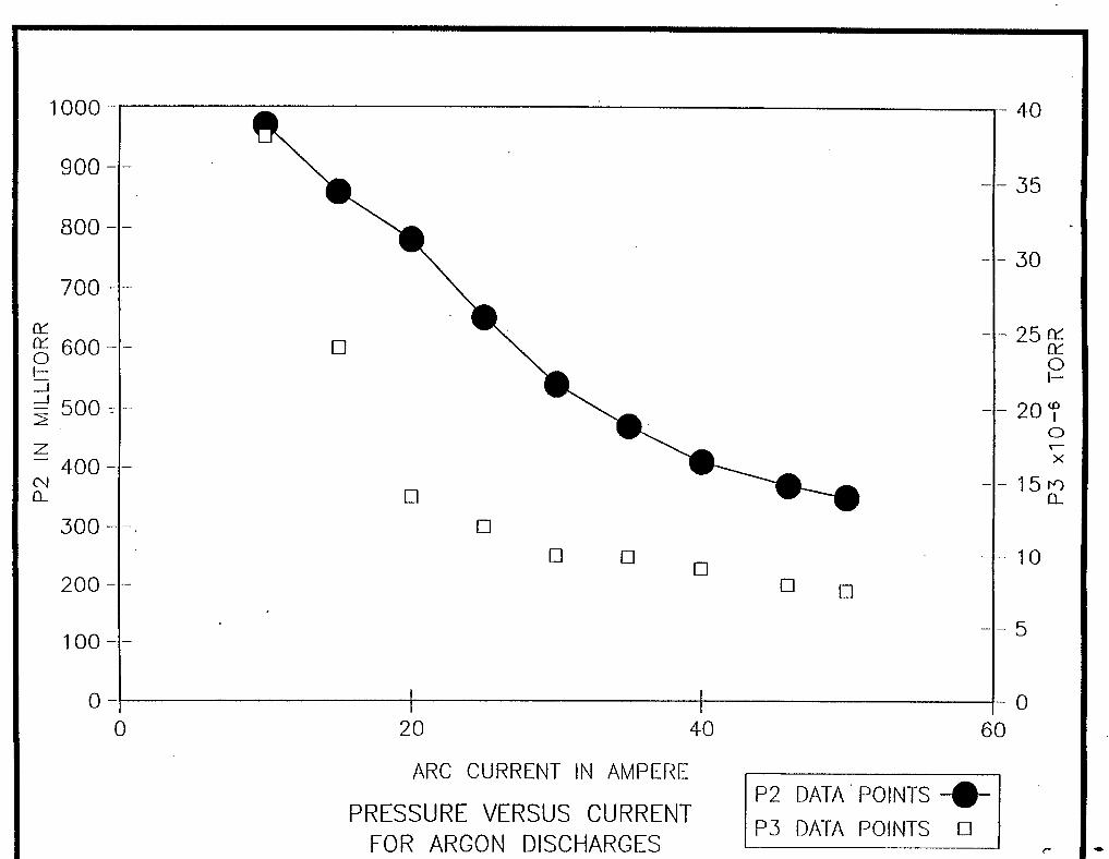
50 A, the pressure at Pz decreased with increasing arc current, reaching 350 mTorr at 50 A. This
represents a reduction by a factor of 228.6 over differential pumping.
- 10-
. . -. . .
P
(I
Figure 2 shows the pressures P2 and P, as a function of the arc current for discharge in argon,
P, was at 760 Ton. Next, the gas feed was switched to helium, and the same measurements were
repeated with helium as the discharge gas. The results were similar, although the pressures at Pz and
P, were higher by a factor of about 2.8 for the same arc currents.
Qualitatively, the results displayed in Figure 2 are consistent with the theoretical arguments
introduced in the previous section. The plasma and gas temperatures are known to increase with
increasing arc current.[2,3,4] Therefore, the plasma and gas viscosities are expected to rise with
increase in arc current, while the channel gas density is expected to decrease with increasing arc
current. Consequently, P2 and P,, as expected, decrease with increasing arc current. Quantitatively,
based on some previous temperature measurements, [2,3,4] the plasma and gas temperature can be
of the order of 12000°K. Hence, for a room temperature of about 300”K, the effect based on
Equation 1 accounts for a factor of 40 in pressure reduction at P2. The extra factor of 5.7 reduction
in P2 is most likely due to increase in viscosity and momentum transfer.
IIIb. Differential Pumping Experiments With Venturi Gas Feed
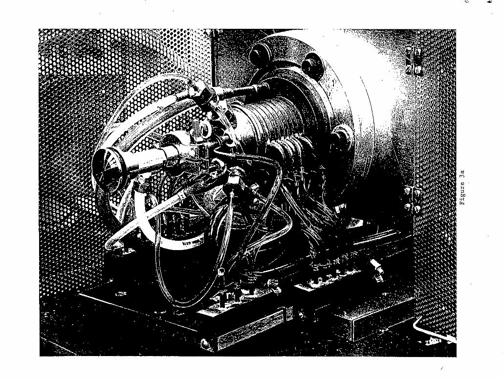
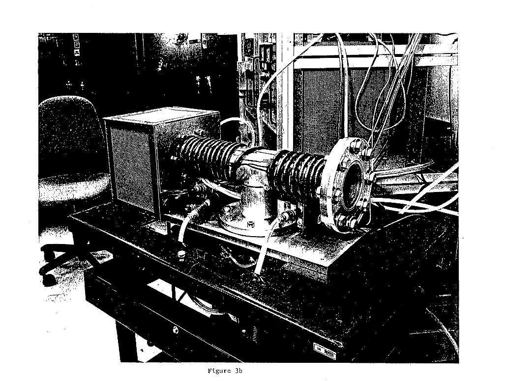
Figures 3a and 3b are photos of an active experiment plasma window set up. On one side of
a 4” diameter “T” is a plasma window (figure 3a), while on the opposite side there is a viewing port.
Figures 4a and 4b are photos of the plasma in the window take from the atmosphere (4a) and through
the viewing port (4b). A venturi (from the left, it is the first component with a gas feed) is novel
feature, which is incorporated in this plasma window. More details of the venturi can be seen in
figure 5. A convectron gauge is used to measure the pressure in the vacuum “T”.
Gas supply for this window is fed through the venturi. The rational for using the venturi is
to utilize the gas to enhance the differential pumping. Experimentally, there was a further
enhancement in the plasma window performance by another factor of 3, i.e., the difference in the
-11-
i
pressure in the “T” (plasma window on versus plasma window off) was a factor of 600. Thus the
enhancement over differential pumping was a factor of 600 with the venturi (compared to 228.6
without the venturi). Additionally, with the venturi, there was a 25% reduction in power consumed
by the plasma window arc. Obviously much of the enhancement can be attributed to pressure
reduction at the cathodes. It is not clear whether there are other contributing factors (like higher
temperature or enhanced viscosity).
IV. DISCUSSION
A 2.3 mm diameter 6 cm long channel filled with helium or argon cascade arc discharge
plasma was successfully used to establish a vacuum-atmosphere interface.
Computations carried out in this paper indicated that ions of interest to ion material
modifications could be successfully transported through such a window, and retain sufficient energy
to perform their task. Due to the large variety of ions and the wide range of ion energies used in
material modifications, detailed andysis of ion beam attenuation and focusing is needed for each
application. Nevertheless, since the principle of this type of focusing had been demonstrated,[ 16,171
and since data[ 181 indicates a reasonable range of ions in air, non-vacuum ion material modification
seems feasible, with such a vacuum-atmosphere interface.
Among some of the benefits of using this type of vacuum-atmosphere windows are the
increase in production rate, and the potential of performing various types of ion material
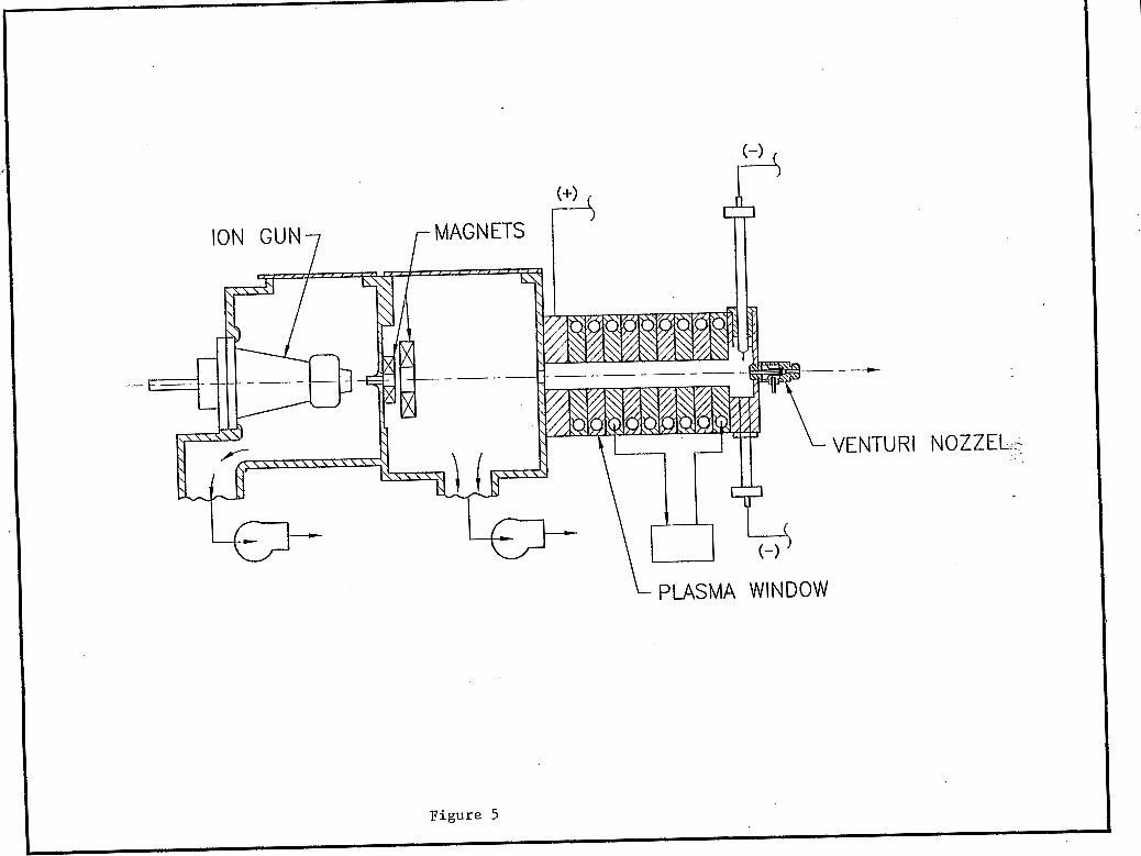
modifications on large work pieces and in previously inaccessible places. An ion gun coupled to a
plasma window is shown in Figure 5, the cooling plates can be miniaturized to provide for a long
narrow discharge channel, to reach previously inaccessible places.
- 12-

a
d
V. ACKNOWLEDGMENTS
Many thanks to Daan Schram and his group at Eindhoven (especially Ries van de Sande) for
help with the cascade arc device. Excellent technical support was provided by Whitey T r a m and
Walt Hensel. Special thanks to Dave Langiulli for his support of this project. Contribution from
students Peter Kollman and Alex Jeffers was invaluable in setting up the experiments and in data
collection. Special thanks to my new collaborators Erik Johnson and Peter Stefan for their
contributions to the new plasma window setup and experiments.
- 1 3 -
I
1
REFERENCES
A. Hershcovitch, J. Appl. Phys. 78,5283 (1995).
C.J. Timmermans, R.J. Rosado, and D.C. Schram, Z. Naturforschung a, 81 (1985).
G.M.W. Kroesen, D.C. Schram, and J.C.M. de Haas, Plasma Chemistry and Plasma
Processing D , 5 3 1 (1 990).
J.J. Beulens, D. Milojevic, D.C. Schram, and P.M. Vallinga, Phys. Fluids B, 3,2548 (1991).
L.D. Landau and E.M. Lifshitz, "Fluid Mechanics", Addison-Wesley Publishing Go.,
Reading, Mass., 1959.
R.L. Daugherty and A.C. Ingersoll, ''Fluid Mechanics", McGraw-Hill Book Go., Inc., 1954.
S.I. Braginskii, 'Transport Processes in a Plasma", Reviews of Plasma Physics, Vol. 1,
(Consultants, Bureau, New York, 1965).
S . Chapman and T.G. Cowling, "The Mathematical Theory of Non-Uniform Gases",
Cambridge, England, The University Press, 1939.
W.H. Bennett, Physical Review 45,890 (1 934).
D.C. Schram, private communication, 1993; although this fractional ionization can be as high
as 20%.
Expressions derived from H.A. Bethe's work, e.g., J.D. Jackson, "Classical
Electrodynamics", Second Edition, Wiley, New York, 1975. And B. Rossi, "High Energy
Particles" Englewood Cliffs: Prentice-Hall, 1952.
- 14-
- . . . . - . . - . .
2 [12] B.A. Trubnikov, Tarticle Interactions in a Fully Ionized Plasma", Reviews of Plasma
Physics, Vol. 1, (Consultants Bureau, New York, 1965).
P.D. Prewett, Rev. Sci. Instqm. 63,2364 (1992).
H.A. Bethe, Ann. Physik 5,325 (1930).
H.A. Bethe, Z. Physikz, 293 (1932).
M. Giesch, B. Kuiper, B. Langeseth, S . Van Der Meer, D. Neet, G. Plass, G. Pluym, and B.
\
[13]
[ 141
[l5]
[16]
De Raad, NIM 2 , 5 8 (1963).
C.L. Olson, J. Fusion Energy 1,309 (1982).
R.D. Evans, "The Atomic Nucleus", McGraw-Hill Co., New York, 1970; see, e.g., data in
[ 171
[18]
Chapt. 22 on range of a particles and fission fraagments in air, J. Boggild, K. Bronstrom, and
T. Lauritsen, Phys. Rev. 59,275 (1941).
, . . - .
- 15-

FIGURE CAPTIONS
\
1. Schematic (not to scale) of the setup for the vacuum-atmosphere interface experiment. The
cascade arc is enlarged to show details of its main components: cathodes and cooling plates.
P2 is measured in a 4" pipe, while P3 is measured in a box whose dimensions are 2' x 2.5' x
4'.
2. With P, = 760 Torr,
discharges.
Photos of the new experimental setup showing: (a) the plasma window, (b) view port.
Plasma channel photo taken: (a) from atmosphere, (b) through viewing port.
Schematic of an ion gun couple to a plasma window, which can be used for implantation
etching, or micro-fabrication.
and3P are displayed as a function of the arc current in argon
3.
4.
5.
- 16-
. .

LT w
0 I s
W
0 Z -x
n
L I
I .
(3 z
0 I-
fn w
5 n c3 Z =I 0 0 0
I
n X m W
1000 -
900 -
800 -
700 -
L1L 600-
_I
2 - 5 0 0 -
Z
0) a
- 400 --
300 -
200 -
100-
0 - 0
a
0 0
0 0 0
20 40
ARC CURRENT IN AMPERE
PRESSURE VERSUS CURRENT FOR ARGON DISCHARGES
60
P2 DATA' POINTS -.- P3 DATA POINTS 0
- 40
- 35
- 30
- 2 5 w K 0 I-
- 20'f 0
X 7
- 15m a.
- 10
- 5
- 0
t c
e
m

Figure 4a
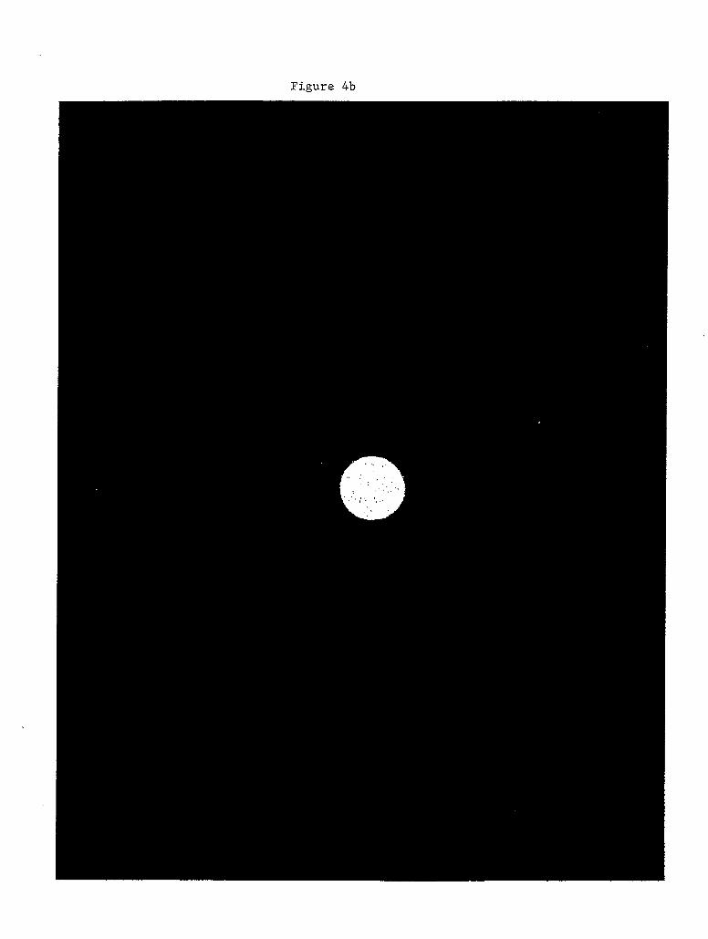
Figure 4b
t
t I
i/
-J
W
N
N
0
Z
CYT 3
I- Z
w
>
-
W I