plasma cleanerthe plasma cleaner is designed for vacuum pumps requiring up to 7 amps. do not plug a...
TRANSCRIPT
www.harrickplasma.com
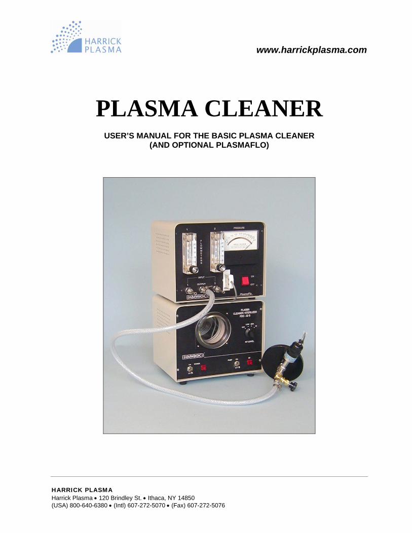
PLASMA CLEANER
USER’S MANUAL FOR THE BASIC PLASMA CLEANER (AND OPTIONAL PLASMAFLO)
HARRICK PLASMA Harrick Plasma • 120 Brindley St. • Ithaca, NY 14850 (USA) 800-640-6380 • (Intl) 607-272-5070 • (Fax) 607-272-5076
TABLE OF CONTENTS
General Information Safety Information ...................................................................................................................... 1Unpacking ................................................................................................................................... 1Technical Support ....................................................................................................................... 1Feedback ....................................................................................................................................
1
About the Plasma Cleaner Principle of Operation ................................................................................................................. 2Getting Started ............................................................................................................................
3
Processing with Room Air Setup .......................................................................................................................................... 4Operation .................................................................................................................................... 4Processing with Gas Setup .......................................................................................................................................... 6Operation .................................................................................................................................... 7Using the Optional PlasmaFlow Getting Ready ............................................................................................................................. 9Setup .......................................................................................................................................... 10Operation ....................................................................................................................................
11
Troubleshooting ..................................................................................................................
13
Appendix A Exchanging Needle Valves .........................................................................................................
14
Appendix B Replacing the Chamber ..........................................................................................
16
Appendix C Optional and Replacement Parts ...............................................................................
17
Appendix D Specifications ..............................................................................................................................
18
PDC32G-M-03
GENERAL INFORMATION
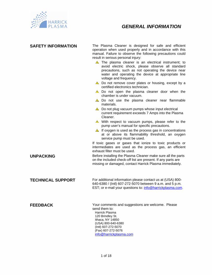
SAFETY INFORMATION The Plasma Cleaner is designed for safe and efficient operation when used properly and in accordance with this manual. Failure to observe the following precautions could result in serious personal injury:
The plasma cleaner is an electrical instrument; to avoid electric shock, please observe all standard precautions, such as not operating the device near water and operating the device at appropriate line voltage and frequency.
Do not remove cover plates or housing, except by a certified electronics technician.
Do not open the plasma cleaner door when the chamber is under vacuum.
Do not use the plasma cleaner near flammable materials.
Do not plug vacuum pumps whose input electrical current requirement exceeds 7 Amps into the Plasma Cleaner.
With respect to vacuum pumps, please refer to the pump user’s manual for specific precautions.
If oxygen is used as the process gas in concentrations at or above its flammability threshold, an oxygen service pump must be used.
If toxic gases or gases that ionize to toxic products or intermediates are used as the process gas, an efficient exhaust filter must be used.
UNPACKING Before installing the Plasma Cleaner make sure all the parts on the included check-off list are present. If any parts are missing or damaged, contact Harrick Plasma immediately.
TECHNICAL SUPPORT For additional information please contact us at (USA) 800-640-6380 / (Intl) 607-272-5070 between 9 a.m. and 5 p.m. EST; or e-mail your questions to: [email protected].
FEEDBACK Your comments and suggestions are welcome. Please send them to: Harrick Plasma 120 Brindley St. Ithaca, NY 14850 (USA) 800-640-6380 (Intl) 607-272-5070 (Fax) 607-272-5076 [email protected]
1 of 18
ABOUT THE PLASMA CLEANER
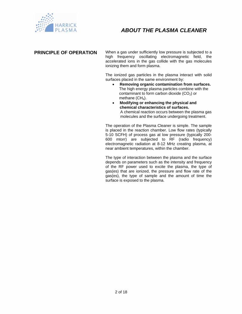
PRINCIPLE OF OPERATION When a gas under sufficiently low pressure is subjected to a
high frequency oscillating electromagnetic field, the accelerated ions in the gas collide with the gas molecules ionizing them and form plasma. The ionized gas particles in the plasma interact with solid surfaces placed in the same environment by:
• Removing organic contamination from surfaces. The high energy plasma particles combine with the contaminant to form carbon dioxide (CO2) or methane (CH4). • Modifying or enhancing the physical and
chemical characteristics of surfaces. A chemical reaction occurs between the plasma gas molecules and the surface undergoing treatment.
The operation of the Plasma Cleaner is simple. The sample is placed in the reaction chamber. Low flow rates (typically 5-10 SCFH) of process gas at low pressure (typically 200-600 mtorr) are subjected to RF (radio frequency) electromagnetic radiation at 8-12 MHz creating plasma, at near ambient temperatures, within the chamber. The type of interaction between the plasma and the surface depends on parameters such as the intensity and frequency of the RF power used to excite the plasma, the type of gas(es) that are ionized, the pressure and flow rate of the gas(es), the type of sample and the amount of time the surface is exposed to the plasma.
2 of 18

ABOUT THE PLASMA CLEANER GETTING STARTED Before starting, take a few moments to familiarize
yourself with the Plasma Cleaner by looking at the drawings of the front and back of the unit (Figures 1, 2).
PLASMACLEANER / STERILIZER
PDC - 32G
LOW MED
Needle Valve
RF Switch
Plasma CleanerDoor
RF LEVEL
HIOFF
ON ON
OFFOFF
RFPUMPPOWER
Figure 1 • Plasma Cleaner Front View (110V Model)
Figure 2 • Plasma Cleaner Back View (110V Model)
Plasma Cleaner Switch Vacuum Pump
Switch
Fitting for vacuum pump
Vacuum Pump Outlet
Vacuum Pump Fuse
3 of 18
Plasma CleanerFuses
Plasma Cleaner Outlet

PROCESSING WITH ROOM AIR SETUP To setup the Plasma Cleaner for processing with room air
(Figure 3): • Connect the fitting at the rear of the Plasma
Cleaner (Figure 2) to the vacuum pump with ½’’ ID vacuum tubing.
• Tighten hose clamps over the tubing at each end. • Plug the Plasma Cleaner in a grounded outlet. • Plug the vacuum pump into the vacuum pump
outlet on the back of the Plasma Cleaner (110V model, Figure 2) or into another outlet (220V model).
CAUTION: The Plasma Cleaner is designed for vacuum pumps requiring up to 7 amps. DO NOT plug a vacuum pump whose input electrical current requirement exceeds 7 amps into the plasma cleaner pump outlet.
Plasma Cleaner
Air
Vacuum Pump
Figure 3 • Diagram for Room Air Processing
OPERATION
EVACUATING THE CHAMBER • Put the sample in the Plasma Cleaner chamber. • Hold the Plasma Cleaner door against the
vacuum chamber. • Turn on the vacuum pump switch on the front of
the Plasma Cleaner (110V model, Figure 1) or on the vacuum pump (220V model). It will take a few minutes to evacuate the air in the Plasma Cleaner chamber. The vacuum will hold the Plasma Cleaner door in place.
4 of 18
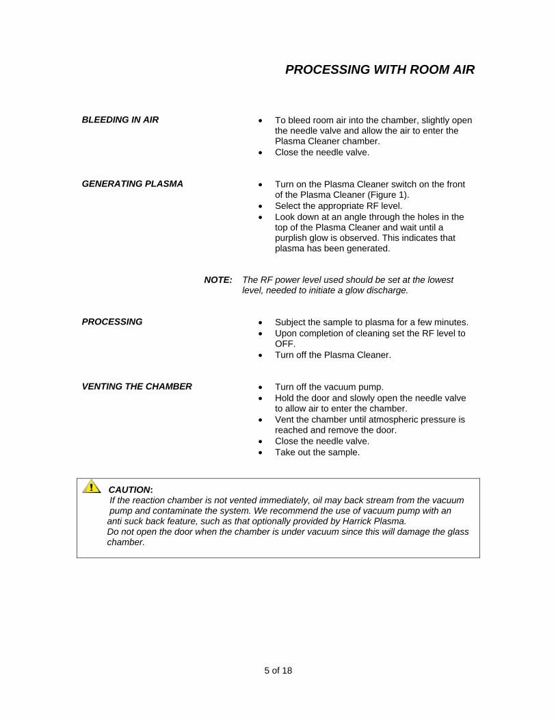
PROCESSING WITH ROOM AIR BLEEDING IN AIR • To bleed room air into the chamber, slightly open
the needle valve and allow the air to enter the Plasma Cleaner chamber.
• Close the needle valve.
GENERATING PLASMA • Turn on the Plasma Cleaner switch on the front of the Plasma Cleaner (Figure 1).
• Select the appropriate RF level. • Look down at an angle through the holes in the
top of the Plasma Cleaner and wait until a purplish glow is observed. This indicates that plasma has been generated.
NOTE: The RF power level used should be set at the lowest level, needed to initiate a glow discharge.
PROCESSING • Subject the sample to plasma for a few minutes. • Upon completion of cleaning set the RF level to
OFF. • Turn off the Plasma Cleaner.
VENTING THE CHAMBER • Turn off the vacuum pump. • Hold the door and slowly open the needle valve
to allow air to enter the chamber. • Vent the chamber until atmospheric pressure is
reached and remove the door. • Close the needle valve. • Take out the sample.
CAUTION: If the reaction chamber is not vented immediately, oil may back stream from the vacuum pump and contaminate the system. We recommend the use of vacuum pump with an anti suck back feature, such as that optionally provided by Harrick Plasma. Do not open the door when the chamber is under vacuum since this will damage the glass chamber.
5 of 18

PROCESSING WITH GAS SETUP To setup the Plasma Cleaner for processing with process gas,
refer to the diagram below (Figure 4) and follow these steps: • Connect the fitting at the rear of the Plasma Cleaner
(Figure 2) to a vacuum pump with ½’’ ID vacuum tubing and hose clamps over the tubing at each end.
• Connect the needle valve on the Plasma Cleaner door (Figure 1) to the gas source through a pressure regulator.
• Plug the Plasma Cleaner in a grounded outlet. • Plug the vacuum pump into the vacuum pump outlet on
the back of the Plasma Cleaner (Figure 2) or into a second outlet.
CAUTION: The Plasma Cleaner is designed for vacuum pumps requiring up to 7 amps. DO NOT plug a vacuum pump whose input electrical current requirement exceeds 7 amps into the plasma cleaner pump outlet.
Vacuum Pump
Plasma Cleaner
Process Gas
Gas
Figure 4 • Diagram for Processing with Gas
NOTE: To be able to monitor and control the pressure and rate of flow of the process gas, we recommend connecting the optional PlasmaFlo (Figure 6).
CAUTION: For processing with pure oxygen, make sure that you use an oxygen compatible vacuum pump. The optional Harrick Plasma oil-based vacuum pumps are NOT oxygen compatible. The hydrocarbon pump oil mist can react with the ozone formed producing a potentially explosive combination. We do offer oxygen service pumps for use with oxygen process gas; please inquire with Harrick Plasma.
6 of 18
PROCESSING WITH GAS OPERATION
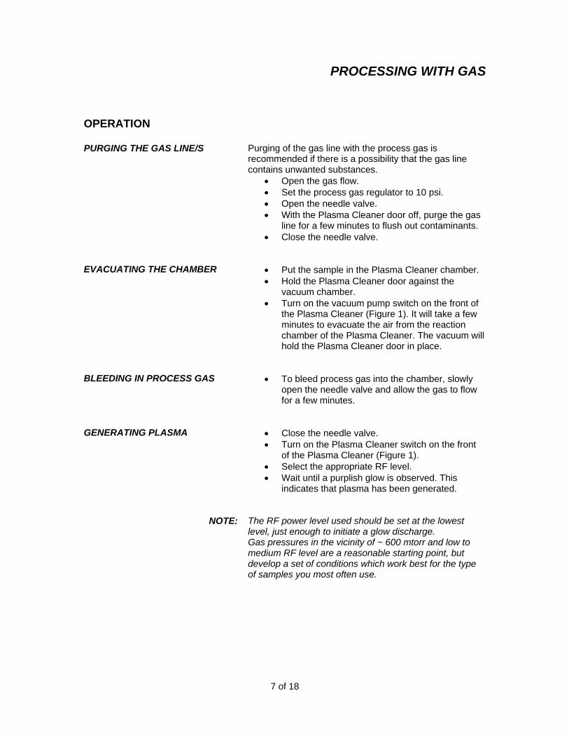
PURGING THE GAS LINE/S
Purging of the gas line with the process gas is recommended if there is a possibility that the gas line contains unwanted substances.
• Open the gas flow. • Set the process gas regulator to 10 psi. • Open the needle valve. • With the Plasma Cleaner door off, purge the gas
line for a few minutes to flush out contaminants. • Close the needle valve.
EVACUATING THE CHAMBER • Put the sample in the Plasma Cleaner chamber. • Hold the Plasma Cleaner door against the
vacuum chamber. • Turn on the vacuum pump switch on the front of
the Plasma Cleaner (Figure 1). It will take a few minutes to evacuate the air from the reaction chamber of the Plasma Cleaner. The vacuum will hold the Plasma Cleaner door in place.
BLEEDING IN PROCESS GAS • To bleed process gas into the chamber, slowly open the needle valve and allow the gas to flow for a few minutes.
GENERATING PLASMA • Close the needle valve. • Turn on the Plasma Cleaner switch on the front
of the Plasma Cleaner (Figure 1). • Select the appropriate RF level. • Wait until a purplish glow is observed. This
indicates that plasma has been generated.
NOTE: The RF power level used should be set at the lowest level, just enough to initiate a glow discharge. Gas pressures in the vicinity of ~ 600 mtorr and low to medium RF level are a reasonable starting point, but develop a set of conditions which work best for the type of samples you most often use.
7 of 18
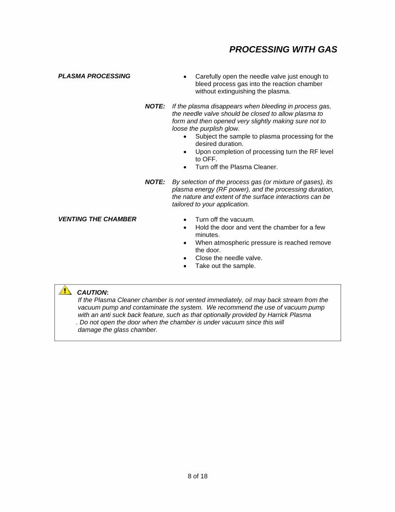
PROCESSING WITH GAS PLASMA PROCESSING • Carefully open the needle valve just enough to
bleed process gas into the reaction chamber without extinguishing the plasma.
NOTE: If the plasma disappears when bleeding in process gas,
the needle valve should be closed to allow plasma to form and then opened very slightly making sure not to loose the purplish glow.
• Subject the sample to plasma processing for the desired duration.
• Upon completion of processing turn the RF level to OFF.
• Turn off the Plasma Cleaner.
NOTE: By selection of the process gas (or mixture of gases), its plasma energy (RF power), and the processing duration, the nature and extent of the surface interactions can be tailored to your application.
VENTING THE CHAMBER • Turn off the vacuum. • Hold the door and vent the chamber for a few
minutes. • When atmospheric pressure is reached remove
the door. • Close the needle valve. • Take out the sample.
CAUTION: If the Plasma Cleaner chamber is not vented immediately, oil may back stream from the vacuum pump and contaminate the system. We recommend the use of vacuum pump with an anti suck back feature, such as that optionally provided by Harrick Plasma . Do not open the door when the chamber is under vacuum since this will damage the glass chamber.
8 of 18
USING THE OPTIONAL PLASMAFLO
9 of 18
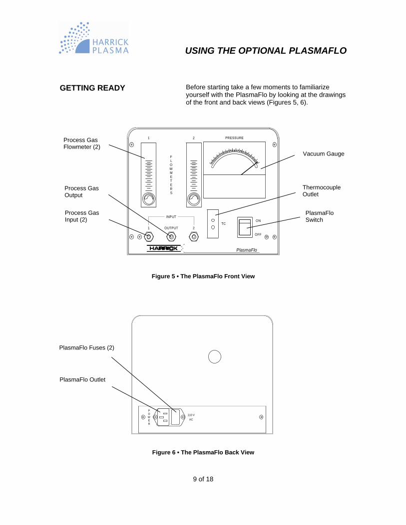
GETTING READY Before starting take a few moments to familiarize
yourself with the PlasmaFlo by looking at the drawings of the front and back views (Figures 5, 6).
ON
2
OFF
INPUT
2
1
1TC
OUTPUT
FLOWMETERS
PlasmaFlo
PRESSURE
Figure 5 • The PlasmaFlo Front View
110 VAC
POWER
Figure 6 • The PlasmaFlo Back View
Process Gas Flowmeter (2)
Vacuum Gauge
Thermocouple Outlet
Process Gas Output
Process Gas Input (2)
PlasmaFlo Switch
PlasmaFlo Fuses (2)
PlasmaFlo Outlet

USING THE OPTIONAL PLASMAFLO
10 of 18
SETUP To setup the Plasma Cleaner for cleaning with gases
using the optional PlasmaFlo (Figures 5, 6), refer to the diagram below (Figure 7) and follow these steps:
• Connect the fitting at the rear of the Plasma Cleaner (Figure 2) to the vacuum pump with ½’’ ID vacuum tubing and hose clamps over the tubing at each end.
• Connect the needle valve on the Plasma Cleaner door to the output on the front of the PlasmaFlo.
• Plug the thermocouple gauge attached to the Plasma Cleaner door into the thermocouple outlet on the front of the PlasmaFlo.
NOTE: If the PlasmaFlo was purchased separately from the Plasma Cleaner, the regular needle valve needs to be replaced with the needle valve with the attached thermocouple gauge (See Appendix A).
Vacuum Pump
Process Gas
Vacuum Gauge Connection
PlasmaFlo
Gas
2
Gas
1
Plasma Cleaner
Figure 7 • Diagram for Processing Using the PlasmaFlo
USING THE OPTIONAL PLASMAFLO
11 of 18
• Connect the gas source/s to the input/s on the
front of the PlasmaFlo. • Plug the Plasma Cleaner and the PlasmaFlo into
grounded outlets. • Plug the vacuum pump into the vacuum pump
outlet on the back of the Plasma Cleaner.
CAUTION: The Plasma Cleaner is designed for vacuum pumps requiring up to 7 amps. DO NOT plug a vacuum pump whose input electrical current requirement exceeds 7 amps into the plasma cleaner pump outlet. OPERATION
PURGING THE GAS LINE/S
Purging of the gas line with the process gas is recommended if there is a possibility that the gas line contains unwanted substances.
• Open the gas flow. • Set the process gas regulator to 10 psi. • Open the needle valve. • With the Plasma Cleaner door off, purge the gas
line a few minutes to flush out any contaminants. • Close the needle valve.
EVACUATING THE CHAMBER • Put the sample in the Plasma Cleaner chamber. • Hold the Plasma Cleaner door against the
vacuum chamber. • Turn on the PlasmaFlo switch on the front of the
PlasmaFlo. • Turn on the vacuum pump switch on the front of
the Plasma Cleaner (Figure 1). It will take a few minutes to evacuate the air from the reaction chamber of the Plasma Cleaner. The vacuum will hold the Plasma Cleaner door in place. Monitor the pressure on the vacuum gauge on the PlasmaFlo.
USING THE OPTIONAL PLASMAFLO
12 of 18
BLEEDING IN PROCESS GAS/S • To bleed process gas/s into the chamber, slowly
open the needle valve. Adjust the amount of gas/s using the flowmeter control knobs on the PlasmaFlo.
GENERATING PLASMA • Turn on the Plasma Cleaner switch on the front
of the Plasma Cleaner (Figure 1). • Select the appropriate RF level. Wait until a
purplish glow is observed. This indicates that plasma has been generated.
NOTE: The RF power level used should be set at the lowest
level, just enough to initiate a glow discharge. Gas pressures in the vicinity of ~ 600 mtorr and low to medium RF level are a reasonable starting point, but develop a set of conditions which work best for the type of samples you most often use.
PLASMA PROCESSING • Subject the sample to plasma processing for a
few minutes. • Upon completion of processing set the RF level
to OFF. • Turn off the Plasma Cleaner.
NOTE: By selecting the process gas (or gas mixture) and plasma
energy (RF power), the nature and extent of the surface interactions can be tailored for your application.
VENTING THE CHAMBER • Turn off the vacuum. • Hold the door and vent the chamber for a few
minutes. • When atmospheric pressure is reached remove
the door. • Close the needle valve. • Remove the sample.
CAUTION: If the Plasma Cleaner chamber is not vented immediately, oil may back stream from the vacuum pump and contaminate the system. . We recommend the use of vacuum pump with an anti suck back feature, such as that optionally provided by Harrick Plasma . Do not open the door when the chamber is under vacuum since this will damage the glass chamber.
TROUBLESHOOTING
13 of 18
MALFUNCTION
POSSIBLE CAUSES CORRECTIVE ACTIONS
plasma fails to form in the chamber
the electronics fails to deliver power to RF coil
Place the miniature fluorescent bulb supplied with the Plasma Cleaner into the chamber. Leave the door open and turn the RF level to HIGH. If the bulb glows, the electronic system is functioning properly. If it does not, check the fuses at the back of the unit. Replace any that are defective and repeat the test with the fluorescent bulb. If this test still fails, contact Harrick Plasma.
the vacuum system fails to sufficiently evacuate the chamber.
If you are using a vacuum pump not supplied by Harrick Plasma, make sure that your vacuum pump is capable of reaching a pressure of 200 mtorr or less. Then check that the vacuum hose is properly attached, the Plasma Cleaner door is properly seated, the o-rings are in place, and that the window is intact. All o-rings should be clean and free of defects.
APPENDIX A
14 of 18
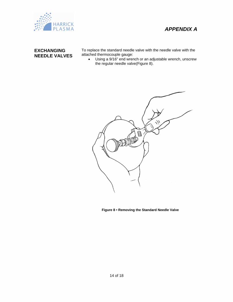
EXCHANGING NEEDLE VALVES
To replace the standard needle valve with the needle valve with the attached thermocouple gauge:
• Using a 9/16” end wrench or an adjustable wrench, unscrew the regular needle valve(Figure 8).
Figure 8 • Removing the Standard Needle Valve
APPENDIX A
15 of 18
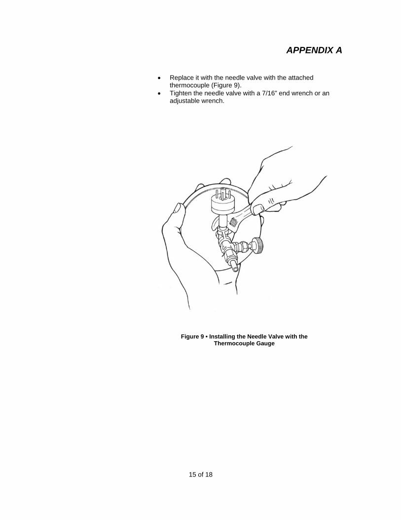
• Replace it with the needle valve with the attached
thermocouple (Figure 9). • Tighten the needle valve with a 7/16” end wrench or an
adjustable wrench.
Figure 9 • Installing the Needle Valve with the
Thermocouple Gauge
APPENDIX B
16 of 18
REPLACING THE CHAMBER To replace the Plasma Cleaner chamber:
• Disconnect the tubing to the chamber. • Loosen the thumbscrew on the fitting for the
vacuum pump on the back of the Plasma Cleaner (Figure 2).
• Pull out the glass chamber. • Slide in the new chamber. • Tighten the thumbscrew on the back of the
Plasma Cleaner. • Reconnect the tubing to the chamber.

APPENDIX C
17 of 18
OPTIONAL AND REPLACEMENT PARTS OPTIONAL PARTS
Premium Vacuum Pump, 110V ............................................................................... PDC-VP Premium Vacuum Pump, 220V ............................................................................... PDC-VP-2 Premium Vacuum Pump Oil .................................................................................... PDC-VP-OIL Economy Vacuum Pump, 110V ............................................................................... PDC-VPE Economy Vacuum Pump, 220V ............................................................................... PDC-VPE-2 Economy Vacuum Pump Oil .................................................................................... PDC-VPE-OIL Fomblin-Based Vacuum Pump, 110V (for Oxygen Service) .................................... PDC-OPF Fomblin-Based Vacuum Pump, 220V (for Oxygen Service) .................................... PDC-OPF-2 Fomblin Fluid for Fomblin-Based Vacuum Pump..................................................... PDC-FMB Dry Scroll Vacuum Pump, 110V (for Oxygen Service)............................................. PDC-OPD Dry Scroll Vacuum Pump, 220V (for Oxygen Service)............................................. PDC-OPD-2 PlasmaFlo, 110V ..................................................................................................... PDC-FMG-1 PlasmaFlo, 220V ..................................................................................................... PDC-FMG-2 Quartz Plasma Chamber ......................................................................................... PDC-32Q Quartz Sample Tray (2.75” x 6.5”)............................................................................ PDC-32T
REPLACEMENT PARTS
Pyrex Vacuum Chamber ......................................................................................... PDC-191-105 Front Cover Assembly .............................................................................................. PDC-191-111 Front Cover O-ring, Viton ........................................................................................ ORV-341 Fluorescent Bulb ...................................................................................................... PDC-FLB REPLACEMENT FUSES
110V (PDC-32G) 220V (PDC-32G-2)
Plasma Cleaner
3 amp, fast acting 3 amp, fast acting
Vacuum Pump
7 amp, fast acting None
PlasmaFlo
0.5 amp, fast acting 0.5 amp, fast acting
APPENDIX D
18 of 18
SPECIFICATIONS PLASMA CLEANER Chamber Dimensions 3” diameter by 7” deep System Dimensions 8” H x 10” W x 8” D System Weight 12 lbs Chamber Material Pyrex Input Power 100 W RF Frequency 8 -12 MHz Inlet 1/8” NPT needle valve Outlet 1/2” O.D. glass or quartz tubing
POWER APPLIED TO RF COIL
Low Setting 6.8 W Medium Setting 10.5 W High Setting 18 W UTILITIES REQUIRED
Vacuum Pump ...................................................................................... minimum pumping speed of 1.4 m3h-1and an ultimate total pressure of 200 mtorr or less
OPTIONAL VACUUM PUMPS Models PDC-VP and PDC-VP-2
Pumping speed 50/60 Hz ..................................................................... 3,2/3,6 m3h-1
Ultimate total pressure .......................................................................... 23 mtorr Motor power .......................................................................................... 250/300 W Weight ................................................................................................... 33 lbs Dimensions ........................................................................................... 9” H x 15” W x 5” D Models PDC-VPE-1 and PDC-VPE-2
Pumping speed 50/60 Hz ..................................................................... 10.2 m3h-1
Ultimate total pressure .......................................................................... 20 mtorr Motor power .......................................................................................... 325 W Weight ................................................................................................... 27 lbs Dimensions ........................................................................................... 9 3/4” H x 15” W x 5 5/8” D

©2004 Harrick Plasma
Manual Part No. PDC32G-M-03