a review of u.s. army ai rcrew-aircraft integration
TRANSCRIPT

NASA Technical Memorandum 85947 USAAVSCOM Technical Memorandum 84-A-5
NASA-TM-85947
1184otJJ,.01flJ
A Review of U.S. Army Ai rcrew-Aircraft Integration Research Programs
David L. Key and Edwin W. Aiken
July 1984
National Aeronautics and Space Administration
111111111111111111111111111111111111111111111 NF00808
""\ '
LlFlf?/I};'Y ;\~I\~;i\
Hi\f\IPI VII~Ciil'llh.
United States Army Aviation Systems Command

NASA Technical Memorandum 85947 USAAVSCOM Technical Memorandum 84-A-5
Review of U.S. Army ircrew- ircraft
Integration Research Programs Edwin W. Aiken, Ames Research Center, Moffett Field, California
David L. Key, Aeromechanics Laboratory, U.S. Army Research and Technology Laboratories (AVSCOM), Ames Research Center, Moffett Field, California
National Aeronautics and Space Administration
Ames Research Center Moffett Field, California 94035
United States Army Aviation Systems Command St. Louis, Missouri 63120

SUMMARY
A REVIEW OF U.S. ARMY AIRCREW-AIRCRAFT INTEGRATION RESEARCH PROGRAMS
David L. Key Division Chief
and
Edwin W. Aiken Group Leader, Handling Qualities
Aircrew-Aircraft Systems Division Aeromechanics Laboratory
U.S. Army Research and Technology Laboratories (AVSCOM) NASA Ames Research Center, Moffett Field, California, USA
51-1
Handling qualities have historically been studied in the context of two-crew helicopters by stability and control engineers. Mission management development has been left to engineering psychologists or human factors specialists who have studied cockpit controls and displays independently. The desire of the Army for a one-crew helicopter that can perform the Scout and Attack role is forcing us to integrate these disciplines and concerns. This paper reviews some recent studies and results in these disciplines, describes the need for a more unified approach to support new helicopter development, and describes a plan to develop fundamental principles needed for efficient man-machine interface design.
1. INTRODUCTION
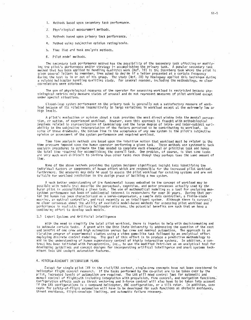
The primary task of the pilot of a two-crew helicopter is to fly the helicopter, that is, to perform the flightpath management function. The co-pilot's responsibilities include most of the other functions: navigation, communication, aircraft systems monitoring, and, in the military role, concern over threats, targets, and battle captain functions of command and control; these responsibilities will be defined as the lIlission management function. If the Army's desire to develop a one-crew version of the Light Helicopter Family (LHX) helicopter is to be realized, both flightpath lIlanagement and mission management will have to be performed by one crew. This single-crew requirement means that flightpath control, that is, stability and control and handling qualities, must be studied in the context of the pilot being burdened with mission lIlanagement tasks, and mission management needs to be studied in the context of a realistic flightpath manageillent task. Historically, handling qualities have been studied by stability and control engineers with no duties other than flightpath control being required of the evaluation pilot. Mission lIlanagement development has been left to engineering psychologists or to human factors specialists who have studied cockpit controls and displays independently. The desire of the Army for a one-crew helicopter that can perform the Scout and Attack role (LHX-SCAT) makes mandatory the integration of these discipl ines and concerns (Fig. 1).
Working under the auspices of the Army/NASA Joint Agreement, the Army Aeromechanics Laboratory and NASA Ames Research Center have been pursuing both of these topics: handling qualities and human factors. This paper reviews some of the studies and results from the individual program elements; first, the stability and control and handling qualities, or flightpath management topics, and second, the human factors or lIlission management work. The final section of this paper describes the need for a more unified approach to support the LHX development and a plan for a new initiative to develop fundamental principles which are needed for efficient man-machine interface design.
2. FLIGHTPATH MANAGEMENT
The ability of a rotorcraft pilot to perform the flightpath management function is determined by the handling qualities of the vehicle: "those qualities or characteristics of an aircraft that govern the ease and precision with which a pilot is able to perform the tasks required in support of an aircraft role" (Ref. 1). Handling qualities are determined not only by the stability and control characteristics of the vehicle, but also by the displays and controls which define the pilot-vehicle interface, the environmental characteristics, and the performance requirements for the task (Fig. 2).
The analysis of the effects of rotorcraft handling qualities on mission effectiveness is broken down into two components: (1) a determination of the influence of handling qualities parameters on the performance of the pilot-vehicle combination and on the physical and mental workload of the pilot, and (2) an analysis of the effects of the achieved precision of flightpath control and workload capacity of the pilot on selected measures of mission effectiveness. Handling qualities investigations by both NASA Ames and Army Aeromechanics Laboratory researchers have concentrated on the former component; these experiments have focused on nap-of-the-earth (NOE) mission tasks conducted during daytime or night/adverse weather conditions by a two-crew aircraft in which the pilot is only required to perform the flightpath ma~agement function. These programs have investigated either generic handling qualities effects or the handllng qualities characteristics of specific rotorcraft configurations; the results of both types of programs are being used as sources of data upon which a revision to the U.S. military helicopter handling qualities specification, MIL-H-8501A, can be based (Ref. 2).
This section summarizes the results of NOE handling qualities investigations, for both day and night/ adverse weather conditions, and describes an initial effort to relate achieved system performance and pilot workload to mission effectiveness.

51-2
2.1 NOE Flight Under Visual Meteorological Conditions
An initial series of helicopter handling qualities studies - including analysis, piloted simulation, and flight research (Table 1) - was conducted to assess the effects of rotor design parameters, interaxis coupling, and various levels of stability and control augmentation (Ref. 3). As a result, recommendations were made for: (1) minimum levels of pitch and roll damping and sensitivity; (2) maximum values of pitchro 11, co 11 ect i ve-to-pitch, and co 11 ecti ve-to-yaw coup 1 i ng; and (3) generi c stabi 1 ity and contro 1 augmentation system (SCAS) requirements.
The effects of thrust-response characteristics on helicopter handling qualities have, until recently, remained largely undefined. Helicopter thrust is influenced by several factors, including (1) engine governor dynamics, (2) vertical damping resulting from rotor inflow, and (3) the energy stored in the rotor, which is a function of rotor inertia. A multiphase program is being conducted to study these effects on helicopter handling qualities in hover and in representative low-speed NOE operations. To date, three moving-based piloted simulations (Refs. 4 and 5) have been conducted on the Vertical Motion Simulator (VMS) at Ames (Fig. 3). It was found that variations in the engine governor response time can have a significant effect on helicopter handling qualities. For the tasks evaluated, satisfactory handling qualities and rpm control were achieved only with a highly responsive governor, but increases in rotor inertia (thus in the stored kinetic energy) have only a minor, though desirable, effect on handling qualities (Fig. 4). The excess power requirement (T/W) was found to be a strong function of Zw and is minimized at a Zw-value around -0.8 rad/sec. The effect on handling qualities of requirements for pilot monitoring and control of rotor rpm can be significant. For a slow engine governor, the degradation in pilot rating in the bob-up tasks was as much as two ratings (Fig. 5). Techniques to relieve the pilot of the task and concern for monitoring proper rpm therefore need to be considered.
In support of the U.S. Army's Advanced Digital/Optical Control System (ADOCS) program, a series of piloted simulations was conducted both at the Boeing Vertol facility and on the VMS to assess the interactive effects of side-stick controller (SSC) characteristics and stability and control augmentation on handling qualities. An initial experiment (Ref. 6) revealed that angular rate stabilization in pitch and roll was sufficient to provide satisfactory handling qualities when a two-axis SSC was employed for control of those axes; however, when a rigid three- or four-axis device (which added directional and directional-plus-collective control, respectively, to the SSC) was employed, attitude stabilization was required to maintain adequate handling qualities. These results were substantiated and expanded upon by the Ref. 7 experiment which demonstrated that a four-axis. small-deflection SSC yielded satisfactory handling qualities for NOE tasks when integrated with a SCAS that incorporated higher levels of augmentation; however. separated controllers (Fig. 6) were required to maintain satisfactory handling qualities for the more demanding control tasks or when reduced levels of stability and control augmentation were provided.
Current research programs being conducted to support the development of the handling qualities specification include investigations of roll-control requirements, hover and low-speed directional control characteristics and helicopter air combat maneuverability and agility requirements.
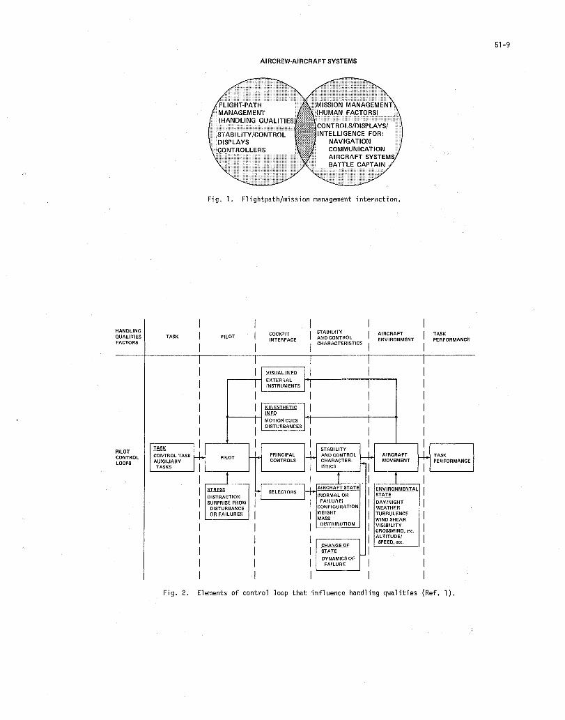
A major shortcoming in the current handling qualities data base is known to be roll-control effectiveness. This critical and fundamental criterion can have a major effect on the basic design of a helicopter. Analyses and piloted simulations are being conducted to assess required levels of damping and the control power required to trim, to recover from external upsets. and to maneuver for various rotorcraft configurations operating in an NOE environment. Similarly. to compensate for a lack of mission-oriented handling qualities data. a piloted simulation is being conducted to evaluate the effects of: (1) mission task requirements; (2) basic yaw sensitivity and damping; (3) directional gust sensitivity; and (4) yaw SCAS implementation on the handling qualities of generic-LHX candidates, including ti~t-rotor, coaxial rotor, and no-tail-rotor configurations (Fig. 7).
To support the requirement for an air-to-air combat capability for future military helicopters, a facility is being developed which can be used to investigate handling qualities requirements in terrain flight air combat. One-on-one air combat (Fig. 8) is simulated using the VMS as the cockpit of the friendly aircraft which is engaged in a computer-generated visual data base by an enemy aircraft which may be flown manually from a fixed-base station or automatically through an interactive maneuvering algorithm. Variations in the performance. stability and control, controllers, and displays of the friendly aircraft are being investigated.
2.2 Effects of Night/Adverse Weather Conditions
The requirement that military rotorcraft operations be conducted at night and under other conditions of limited visibility has given impetus to research programs designed to investigate the interactive effects of vision aids and displays on NOE handling qualities.
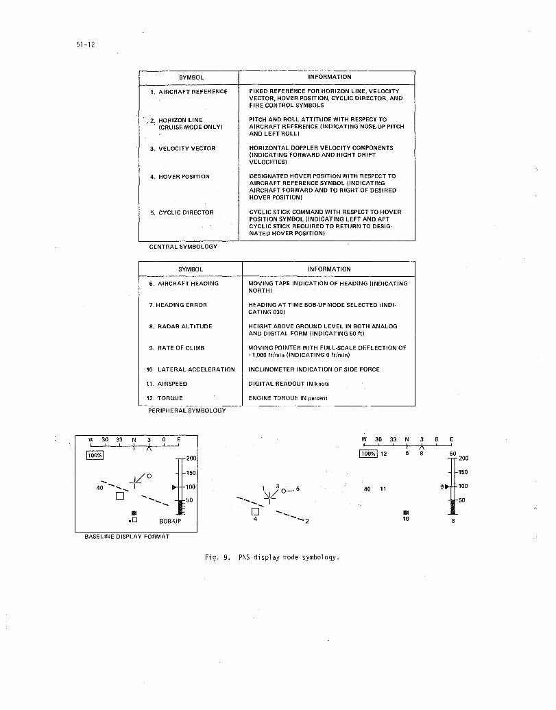
In a program conducted to support the development of the Advanced Attack Helicopter (AAH), various levels of stability and control augmentation together with variations in the format and dynamlcs of the symbols provided on the Pilot Night Vision System (PNVS) (Fig. 9) were investigated in a piloted simulation (Ref. 8). It was found that the handling qualities of the baseline control/display system were unsatisfactory without improvement; recommendations for alterations to the PNVS symbol dynamics and the implementation of a velocity-command system for a hover/bob-up/weapon delivery task were made to the Army Program Manager.
An investigation involving the simulation of a less complex night vision aid was carried out to support the Army Helicopter Improvement Program (AHIP) (Ref. 9). In this simulation, the effects of presenting the PNVS flight symbology on a panel-mounted display (PMD) versus a head-up display (HUD) w~re co~-. pared for a nighttime scout helicopter mission in which the pilot was provided with simulated nlght V1Slon goggles. Although no clear preference for the HUD or PMD was established, the use of the display improved handling qualities for the lower levels of augmentation. However. higher levels of augmentation. which

51-3
included a velocity-command system and augmentation of the directional and vertical axes, were requi red for satisfactory handling qualities.
The state-of-the-art night vision system for combat helicopters includes a visually coupled helmetmounted display of infrared imagery and superimposed symbology: the Integrated Helmet and Display Sight System (IHADSS) (Fig. 10). This system was employed in two simulator investigations (Refs. 10 and 11) designed to assess the effects of reduced visibility conditions on the ADOeS visual flight simulation results cited previously. Significant degradations in handling qualities occurred for most tasks flown with the IHADSS relative to the identical tasks flown under visual flight conditions (Fig. 11). In general, higher levels of stability augmentation were required to achieve handling qualities comparable to those achieved for the visual flight tasks.
2.3 Handling Qualities Effects on Mission Effectiveness
A preliminary computer simulation was conducted to relate certain handling qualities effects, such as preCision of flightpath control and pilot workload, to the ability of a single scout helicopter, or helicopter team, to accomplish a specified anti-armor mission successfully (Ref. 12). A key feature of the program is a simulation of microterrain features and their effects on detection, exposure, and masking
, for NOE fl ight.
For the purpose of this study, degraded scout helicopter handling qualities were assumed to manifest themselves in four ways: (1) increases in the basic NOE altitude at which the helicopter can fly at a given speed, (2) increases in the amount and frequency content of altitude excursions above the basic NOE altitude, (3) 'increases in the amount and frequency content of altitude excursions in hover above that required for observation, and (4) decreases in the amount of visual free time available to the crew for surveillance and fire control functions. The effects of each of these parameters on selected measures of effectiveness (MOE) were investigated separately for three different combat scenarios. These MOE included primary measures such as: (1) the probability of the scout(s) being killed: PK(B), (2) the number of enemy vehicles killed: NK(R), and (3) the exchange ratio: number of enemy vehicles killed divided by the number of scouts killed (E/R). Certain intermediate MOE, involving detection probabilities and average times required to detect and kill, were also analyzed to gain further insight into the engagement outcomes.
In order to assess the overall effect of handling qualities on the MOE, three "grades" of handling qualities - "perfect," "fair," and "bad" - were defined by specifying the associated values of basic NOE altitude, NOE altitude error, hover altitude error, and visual free time. The resultant values of the primary MOE for each grade of handling qualities are presented in Fig. 12.
This study demonstrated that handling qualities do have a significant effect on the ability to perform a specific mission, as indicated by variations in the selected MOE. This effect resulted primarily from variations in the probability of the scout helicopter being detected, particularly during a precision hover.
3. MISSION MANAGEMENT
The objectives of the mission management or human factors part of the program are: (1) to explore and develop the fundamental principles and methodologies necessary to exploit pilot perceptual, motor, and information processing capacity for application to advanced helicopter cockpit deSign, and (2) to develop objective and predictive techniques for assessing pilot workload.
One of the first experimental efforts under this program to address the pilot control/display interface was to determine the relative location of flight displays and the corresponding controls. Specifically, the altimeter and rate of climb indicators which are conventionally located to the right of the pilot centerline indicate parameters which are controlled by the collective stick in the left hand. The flexibility of new electronic display formats such as the PNVS (see Section 2) afforded a reasonable opportunity to determine if there was any penalty caused by this opposite or contralateral control display relationship. In the previously mentioned PNVS study (Ref. 13) most of the pilots preferred a same side (ipsilateral) arrangement. An experiment was conducted to test for any measurable differences in the time to effect control when the display is contralateral rather than ipSilateral to the controller.
Performance was assessed based on reaction time and total time to null the error. An index of difficulty for performing the task was hypothesized based on Fitts law (Ref. 14) which indicates that the time to effect a reduction in error amplitude, A, to a given target with width, W, varies in a linear fashion with the index of difficulty defined as IO ~ A + B log2(2A/W). Thus, the total performance time could be plotted versus ID as shown in Fig. 13. A surprising result is the difference in slopes of the two cases, since this implies that an increase in the difficulty of task propagates into the control phase.
To investigate the same question in a more realistic situation, the experiment was repeated with both collective and cyclic controls being used to null errors simultaneously (Ref. 15). In this experiment the rudder pedals also required attention to null a randomly disturbed heading reference symbol. The display was as shown in Fig. 14. For the ipsilateral case, the V- and H-scales were interchanged. The index of difficulty for the two-axis task was redefined by simply summing the ID defined by the previous equation for the two components of the task. Subjective reports indicated that this definition did not reflect the actual difficulty of the dual task. For example, combinations with both targets on the same side of center (up or down) were easier to capture than targets with the same ID having targets on opposite sides of center, and any combination that included one wide target was easier than a combination with the same 10 but containing a narrower target. These findings suggest that more work will be required to establish a meaningful index of difficulty for two-axis tasks.
51-4
Other interesting results are illustrated by Fig. 15 which shows that the first response and first capture of target were faster with the contralateral configuration, but the second response and second (final) capture were faster with the ipsilateral configuration. This result suggests that the contralateral display makes it difficult for the subjects to develop a strategy for both controls so that they react to one target at a time, thus initiating the movement sooner (initial response) but taking longer to complete the task (final capture) since the final capture requires manipulating both controls simultaneously. If this analysis is correct, the question as to whether or not the traditional contralateral control display configuration is the most efficient for helicopters depends on whether a configuration that encourages a segmented processing and movement strategy is better than one that elicits a more integrated natural response. This question has not yet been addressed.
Another study on cockpit flight controls was performed under contract by Sikorsky Aircraft Division (Ref. 16). The experiment investigated the use of multi-axis sidestick controls for flightpath control in configurations such as were developed for the ADOCS program and the simultaneous performance of a keyboard entry task with the free hand. As would be expected, the results show that keyboard entry tasks interfere with the performance of flightpath tracking, and, conversely, the flightpath tracking interfered with keyboard entry. If a degradation in performance occurs, the use of a multi-axis controller to free a hand for mission management tasks may not be appropriate. The ADOCS data (Section 2) generally show that for most tasks, with a high level of SCAS, similar pilot ratings can be obtained independently of the level of controller integration. However, as the SCAS degrades, separated controls generally become superior. This result has implications on reliability which must be designed into the flight control system SCAS; the four-axis controller may imply a mission-critical SCAS, or even a flight-critical SCAS at more complex levels. This requirement may force the costs associated with a fully integrated controller to a prohibitively high level.
An alternative approach, which provides the ability to change control and display functions without removing the hand from the flight controls or directing visual attention to switch or function locations, would be attractive in an NOE environment and is a logical situation in which to incorporate voice command and display technology.
3.1 Voice Command and Display (SCADS)
It has recently become technologically feasible for the pilot to control onboard systems by voice command, and to receive feedback on this control process via synthesized speech. Research has been performed at Ames on both of these aspects for several years. The helicopter environment makes the accomplishment of accurate automatic speech recognition difficult because of the noise and vibration, as well as physiological and psychological factors such as stress, fear, and fatigue. However, studies have shown encouragingly high accuracy rates.
Development of speech output principles has also been pursued for several years, and an example of applying these concepts is the voice interactive electronic warning system (VIEWS) research project con-, ducted at the Aeromechanics Laboratory.
This study (Ref. 17) was conducted at the request of the Aircraft Survivability Equipment (ASE) Program Manager (PM) and was designed to examine the use of an integrated visual and speech display for a threat warning system. The current Radar Warning Receiver (APR-39) uses a combination of visual strobe lines and proportional rate frequency audio (PRF) tones to give pilots information concerning the location of enemy radar emitters. The PM requested assistance in defining a set of visual symbols to replace the strobe lines, and a set of voice messages to replace the PRF tones. Integrated displays create a new set of problems not found in visual or speech displays alone. The two most apparent problems are display priority and temporal veridicality.
Display priority - Visual displays can display more than one item of information simultaneously; speech displays can only present one item of information at a time. Most visual displays do not attempt to prioritize information; this task is left to the pilot. Speech displays must prioritize information output if they are to be effective. This system prioritization can ease the decisionmaking task of the pilot, but this requires higher levels of "intelligence" on the part of the system.
Temporal veridicality - Visual displays, because of their instantaneous nature can change rapidly to always give veridical information; speech systems, because of the time required to articulate a message may lag behind actual events, particularly if the messages are stored and delivered as strings of words. Integrated visual and speech displays may therefore give conflicting information and cause a pilot to lose confidence in the system.
The following are some of the points which resulted from the VIEWS project:
1. The prioritization logic eliminated all message cueing and updated each word just prior to it being spoken. It also implemented a message update called a "coda" at the end of a message that has been spoken while the real time situation was changing. This coda eliminated the need to repeat a whole message to give an up-to-date output.
2. A special symbol (message being spoken pointer) was displayed on the visual display screen directly under the visual symbol that the speech message was addressing. Thus the pilot always knew which visual symbol the speech display was talking about.
3. It was determined through testing that pilots could use either the visual or speech systems to successfully avoid radar guided threats, but they preferred to have both systems working together.
3.2 Pilot Workload Assessment
Several approaches towards assessing pilot workload have been proposed. According to a study by Phatak (Ref. 18) these methods fall into the following general categories:
51-5
1. Methods based upon secondary task performance.
2. Physiological measurement methods.
3. Methods based upon primary task performance.
4. Method using subjective opinion rating/scale.
5. Time line and task analysis methods.
6. Pilot model methods.
The secondary task performance method has the possibility of the secondary task affecting or modifying the pilot's performance and/or' strategy in accomplishing the primary task. A popular secondary task method that has been applied to handling qualities work (Ref. 19) is the Sternberg task where the pilot is given several letters to remember, then asked to decide if a letter presented at a certain frequency during the test is in or out of his group. The study (Ref. 20) by Hemingway applied this technique during a related helicopter handling qualities study. For several reasons, including the methodology, no clear correlations were obtained.
The use of physiological measures of the operator for assessing workload is restricted because physiological metrics only measure states of arousal and do not represent measures of pilot workload except under special situations.
Closed-loop system performance on the primary task is generally not a satisfactory measure of workload because of its relative insensitivity to large variations in workload except at the extremely low or high levels.
A pilot's evaluation or opinion about a task provides the most direct window into the mental perception, or notion, of experienced workload. However, even this approach is fraught with methodological problems related to standardization of terminology and the large degree of intra- and inter-subject variability in the subjective interpretation of the factors perceived to be contributing to workload. In spite of these drawbacks, the bottom line in the acceptance of any new system is the pilot's subjective opinion or assessment of the system performance and required workload.
Time line analysis methods are based upon the intuitive notion that workload must be related to the time pressure imposed upon the human operator performing a given task. These methods use systematic task analysis procedures to estimate the time needed to complete each elemental or primitive task and hence the total time required for accomplishing the overall task. One problem, of course, is that some tasks are very much more difficult to perform than other tasks even though they perhaps take the same amount of tine.
None of the above methods provides the system designer significant insight into identifying the individual factors or components of human effort which are responsible for the increased pilot workload. Furthermore, the measures may only be used to assess the pilot workload for existing systems and are not suitable for workload prediction in the design phase of building a new system.
A much better understanding of the fundamental issues embodied in the concept of workload may be possible with models that describe the perceptual, cognitive, and motor processes actually used by the human pilot in accomplishing a given task. The use of mathematical modeling as a tool for analyzing mansystems performance has been of substantial interest to researchers for over 30 years. During that period the human has been characterized as a servo-compensator, a sample data controller, a finite-state machine, an optimal controller, and most recently as an intelligent system. Although there is currently no clear consensus about the utility of available model-based methods for assessing pilot workload and perfo~lance in realistic military helicopter missions, the potential benefits are such that we have a continuing effort to develop such models.
3.3 Expert Systems and Artificial Intelligence
With the need to simplify the total pilot workload, there is impetus to help with decisionmaking and to automate certain tasks. A grant with the Ohio State University is addressing the question of the cost and benefit of one crew and high automation versus two crew and nominal automation. The approach is an iterative program of experimental studies using a video game-like task followed by an analytical effort employing discrete control mcdeling. The goal of this effort is to produce a predictive methodology to aid in the understanding of human supervisory control of highly interactive systems. In addition, a contract has been initiated with Perceptronics, Inc., to use the modified Petri-net as an analytical tool for developing guidelines and concept designs for incorporating artifical intelligence and smart systems techniques into LHX cockpit automation features.
4. AIRCREW-AIRCRAFT INTEGRATION PLANS
Except for single pilot IFR in the civil/FAA context, single-crew concepts have not been considered in helicopter flight control research. If the tasks performed by the co-pilot are to be taken over by the pilot, increased levels of automation are required. The LHX will need control laws for automatic and manual control of flightpath including integration with propulsion, fire control, and navigation functions. Configuration effects such as thrust vectoring and X-force control will also have to be taken into account if the LHX configurations is a compound helicopter, ABC configuration, or a tilt rotor. In addition, concepts for safety-of-flight automation will have to be developed for such functions as obstacle avoidance, threat avoidance, flight-envelope limiting, and automatic failure recovery.

51-6
These developments will have to rely heavily on ground-based simulation and will require highfidelity dynamic simulation such as will be available in the Rotorcraft Systems Integration Simulator (RSIS) (Ref. 21) at Ames Research Center. In addition, to adequately represent the pilot's missionmanagement functions such as battle captain tasks, navigation, and aircraft systems management, it will be necessary to develop surrogate tasks which can be incorporated in the simulation on a realistic realtilre basis; the cognitive workload associated with battle management may have a significant impact on total mission performance and realistic simulation of these functions is considered particularly important.
Numerous LHX Man-Machine issues remain as unknowns. The extremely difficult task of flying NOE at night and in weather will leave the pilot little capacity to perform his battle management functions unless extensive innovation is applied to all the man-machine interface tasks. The allocation of control and display media between manual, visual and voice, the extent of automation, and the application of artificial intelligence/expert systems will have to be extensive, yet little is known to guide the appropriate choice of these applications.
For the night and poor weather situations, candidate external scene visual displays which will permit single-crew operation for the LHX mission tasks must be assessed. Wide field-of-view display devices are in the embryonic stage even for ground-based simulators; other display devices, such as night vision goggles, HUD, and IHADSS, have not been applied to such a demanding role. Sensor fusion and real-time image processing for both flight and target tasks have not been developed for an operational system. Not only are hardware advances needed, but a better knowledge of the required functional capabilities, such as field-of-view, resolution, detail, and image update rates, must also be developed to guide the hardware design objectives.
In addition to the outside world visual scene, it will be necessary to display to the pilot an easily understood image of the tactical situation and navigation functions. The achievement of this capability will require the development of real-time tactical situation scenarios which can be used to investigate the man-machine interface required for battle captain functions such as target engagement and threat defense.
Artificial intelligence and expert systems will be required to aid the pilots' decisionmaking tasks and to automate routine prescribed functions. Replacement or supplementation of specific manual controls and visual displays with speech recognition and speech generation techniques is intuitively appealing for pilot workload reduction. However, a significant amount of work will be required to determine which functions are best controlled by voice, how these voice modes should be implemented, and how they are to be interfaced with other modes. Finally, a better understanding is required on how a human interacts with a highly automated system so that the dynamics of switching from one automated mode to another, or back to a manual function as the mission needs change can be defined, and so that guidelines can be developed for the synthesis of the total cockpit.
Some of the problems described above will be addressed in the Advanced Rotorcraft Technology Integration program (Ref. 22) and these results will form the basis for the LHX cockpit design. In addition, the work described in Sections 2 and 3 will be expanded to improve understanding of the fundamental questions. In recognition of a lack of a fundamental approach to the pilot-cockpit design, a new initiative has been developed and will be initiated towards the end of FY 1984.
5. ARMY/NASA AIRCREW-AIRCRAFT INTEGRATION PROGRAM
The objective of this joint Army/NASA program is a focused effort to develop a validated predictive methodology: a set of analytic structures with which cost-effective and efficient guidelines and principles for man-machine integration designs can be derived before a commitment to hardware is made. The analytic (modeling) approach is motivated by the high cost of redesign and retrofit of nonoptimal systems and the ever-increasing cost of the training simulators and systems required to support the operational units in the field. The focus of the program will be the mission of a single-crew scout/attack helicopter operating at night, in adverse weather, in the NOE environment. Although the aircraft will employ the most advanced technology, this mission will produce extreme workload, demand superior performance, and require extensive training of the aircrew. The essential issues are the triad of pilot workload, performance, and training which are inexorably intertwined and affect all integrated design considerations in future helicopter cockpits. Current design practice relies on a cut-and-try approach, and on questionable procedures for evaluating effectiveness. Consequently, it is not possible to quantify what is essential to the design of a system for an effective man-machine interface and, therefore, there exist no future benefits from lessons learned.
To achieve the objective, a fundamental understanding must be established of how the human operator processes the information by which he perceives his environment, how he acts upon that perception, how training modified this perception, and how the foregoing relate to pilot performance and workload. Considerable research has already been accomplished in an attempt to understand human perception and cognition and to establish measures of pilot performance and workload. These efforts have generally been ad hoc and fragmented, the results have seldom been focused on the design of a man-machine system and have never been conveyed in terms useful to the engineering user community.
The planned program will be an interdisciplinary effort involving pilots, display engineers, control engineers, mathematicians, and engineering psychologists. Essential tools for this program will be flexible, versatile, ground-based, and in-flight simulator research capabilities that permit the study of the interactions of variations in display laws and control laws on the human's ability to interface with automatic aids in order to perform specified missions. The ground-based simulation capability at Ames is already exceptional and will be augmented when the Rotorcraft Systems Integration Simulator and NASA's Manned Vehicle Research Simulation Facility are put into operation. The in-flight research capability could, for example, be provided by an integration in the UH-60A Black Hawk of the ADOCS flight controls

and NASA/Army digital avionics packages. Inhouse efforts utilizing these unique facilities will be designed to complement contracted work.
The program will consist of seven phases (Fig. 16). A program schedule is shown in Figure 17.
6. (ONCLUSIONS
51-7
Handling qualities research conducted by the U.S. Army Aeromechanics Laboratory and NASA Ames Research Center to date has emphasized the interactive effects of basic stability and control characteristics, type of SCAS, controller characteristics, and vision aids and displays on the ability of a two-crew rotorcraft to conduct specific NOE mission tasks. Extrapolation to the Single-crew situation from these data must be based on sound engineering and piloting judgment.
Numerous single-crew helicopter man-machine issues remain as unknowns. The extremely difficult task of flying NOE at night and in weather will leave the pilot little capacity to perform his battle management functions unless extensive innovation is applied to all the man-machine interface tasks. The allocation of control and display media between manual, visual and voice, the extent of automation, and the application of artificial intelligence/expert systems will have to be extensive, yet little is known to guide the appropriate choice of these applications. To address these concerns a new program is planned which will be an interdisciplinary effort involving pilots, display engineers, control engineers, mathematicians, and engineering psychologists. The objective of this joint Army/NASA program is predictive methodology, a set of analytic structures with which cost-effective and efficient guidelines and principles for man-machine integration designs can be derived before a commitment to hardware is made.
REFERENCES
1. Cooper, G. E. and Harper, R. P., Jr., "The Use of Pilot Rating in the Evaluation of Aircraft Handling Qualities." NASA TN D-5l53, April 1969.
2. Key, D. L., "The Status of Military Helicopter Handling Qualities Criteria." AGARO CP 333, Paper 11, Apri I 1982.
3. Chen, R. T. N., "Unified Results of Several Analytical and Experimental Studies of Helicopter Handling Qualities in Visual Terrain Flight." NASA CP-2219, April 1982.
4. Corliss, L. D. and Blanken, C. L., "A Simulation Investigation of the Effects of Engine- and ThrustResponse Cha racteri st i cs on He 1 i copter Handl i ng Qual it i es . " 9th European Rotorcraft Forum, Paper 62, Sept. 13-15, 1983.
5. Corliss, L. D. and Blanken, C. L., "Effects of Rotor Inertia and RPM Control on Helicopter Handling Qualities." AIAA Paper 83-2070, Aug. 1983.
6. Aiken, E. W., "Simulator Investigation of Various Side-Stick Controller/Stability and Control Augmentation Systems for Helicopter Terrain Flight." AIAA Paper 82-1522, Aug. 1982.
7. Landis, K. H., Dunford, P. J., Aiken, E. W., and Hilbert, K. B., "A Piloted Simulator Investigation of Side-Stick Controller/Stability and Control Augmentation System Requirements for Helicopter Visual Flight Tasks." 39th American Helicopter Society Forum, Paper A-83-39-59-4000, May 1983.
8. Aiken, E. W. and Merrill, R. K., "Results of a Simulator Investigation of Control System and Display Variations for an Attack Helicopter Mission." 36th American Helicopter Society Forum, Paper 80-28, May 1980.
9. Carico, D., Blanken, C. L., Bivens, C. C., and Morris, P. M., "Fixed-Base Simulator Investigation of Display/SCAS Requirement for Army Helicopter Low-Speed Tasks." 39th Annual American Helicopter Society Forum, Paper A-83-39-40-4000, May 1983.
10. Landis, K. H. and Aiken, E. W., "Simulator Investigations of Side-Stick Controller/Stability and Control Augmentation Systems for Night Nap-of-the-Earth Flight." J. of the American Helicopter Society, Vol. 29, No.1, Jan. 1984, pp. 56-65.
11. Aiken, E. W., Hilbert, K. B., Landis, K. H., and Glusman, S. I., "An Investigation of Side-Stick Controller/Stability and Control Augmentation System Requirements for Helicopter Terrain Flight Under Reduced Visibility Conditions." AIAA Paper 84-0235, Jan. 1984.
12. Harris, T. M. and Beerman, D. A.: "Impact of Flying Qualities on Mission Effectiveness for Air Combat." Flight Systems Inc. Report FSI-82-WP-208, June 1983.
13. Hartzell, E. J., Dunbar, S., Beverage, R., and Cortilla, R., "Helicopter Pilot Response Latency as a Function of the Spatial Arrangement of Instruments and Controls." Proceedings of the 18th Annual Conference on Manual Control (1982) USAF AWAL-TR-83-3021, June 1983.
14. Fitts, P. M. and Peterson, R., Jr., "Information Capacity of Discrete Motor Responses." J. Experimental Psychology, Vol. 67, 1964, pp. 103-112.
15. Craig, K. M., "Helicopter Pilot Response as a Function of Compatibility of Control-Display Configuration." MA thesis, Department of Psychology, San Jose State University, May 1983.
16. McGee, J., "An Experimental Investigation of the Interface Between a Right Hand Side Arm Controller Tracking Task and a Left Hand Switch Operation Task." Sikorsky Engineering Report 510128, Jan. 1982.

51-8
17. Voorhees, James W., Boucher, N., Huff, E. N., Simpson, C. A., and Williams, D. H .• "Voice Interactive Electronic Warning System (VIEWS)." Proceedings 5th IEEE/AIAA Digital Avionics Systems Conference, Nov. 1983.
18. Phatak. A. V .• "Review of Model Based Methods for Pilot Performance and Workload Assessment." Analytical Mechanics Associates Report No. 83-7, April 1983.
19. Schiflett. S. G .• "Evaluation of a Pilot Workload Assessment Device to Test Alternate Display Formats and Control Handling Qualities." Naval Air Test Center Report SY-33R-80, July 1980.
20. Aiken, E. W., Blanken, C. L., and Hemingway, J. C., "A Manned Simulator Investigation of the Effects of an Integrated Isometric Controller on Pilot Workload for Helicopter Nap-of-the-Earth Flight." Proceedings 17th Annual Conference on Manual Control (1981) JPL Publication 81-95.
21. Statler, I. C. and Deel, A., "The Role of the Research Simulator in the System Development of Rotorcraft." AGARD CP-3l3, April 1981.
22. Smith, L. K., "LHX: The He 1 i copter Program of the Century." Rotor and Wi ng I nternat i ona 1, Vo 1. 18, No.1, Jan. 1984, pp. 56-70.
TABLE 1. SUMMARY OF INITIAL TERRAIN FLIGHT EXPERIMENTS
Experiments Obj ecti ve Tasks Simulator Rotor type Control system type
To determi ne effect of Longi tudi na 1 verti ca 1 Fi xed base Teeteri ng Basic helicopter large variations in task (Ames S-19) Art i cu 1 ated (rate-type in rotor design parameters Lateral slalom task Hi nge 1 ess pitch, roll, and
Combi ned task yaw)
II To assess effect of Combi ned tas k Moving base Teetering SCAS Input Decoupling various 1 eve 1 s 0 f S CAS (Ames FSAA) Arti cu 1 ated Rate command
Hingeless Attitude command in pitch and ro 11
III To evaluate a sophisti- Combi ned tas k Moving base Hi ngeless SCAS cated SCAS for hinge- (Ames FSAA) Attitude and rate less rotor helicopter Stabilityaugmen-
tation Control augmen-
tation
IV To investigate roll damp- Prescribed lateral I n-fl i ght Teeteri ng Rate-type in pitch, ing, roll sensitivity, slalom course over (UH-1H/ ro 11, and yaw and pitch-roll cross- a runway VSTOLAND) coupling and correlate results with Experiments I and I I
HANDLING QUALITIES FACTORS
PILOT CONTROL LOOPS
TASK
I I I I I I
TASK I --~ CONTROL TASK
AUXILIARY TASKS I
I I I I I I I I
AIRCREW-AIRCRAFT SYSTEMS
Fig. 1. Flightpath/mission management interaction.
PILOT
I I I I 1
I I
PILOT ~
r H DISTRACTION SURPRISE FROM I DISTURBANCE
OR FAILURES I I I I I
COCKPIT INTERFACE
VISUAL INFO
EXTERNAL INSTRUMENTS
KINESTHETIC INFO
MOTION CUES DISTURBANCES
PRINCIPAL CONTROLS
SELECTORS
I I I I
-I
I I ~ I I .,. I I I I I I
STABILITY AND CONTROL CHARACTERISTICS
I I I I 1
I I
STABILITY
~ AND CONTROL CHARACTER· ISTICS I
t I AIRCRAFT STATE I (NORMAL OR
FAILURE) I CONFIGURATION WEIGHT I MASS
DISTRIBUTION I I
CHANGE OF
I STAT];
DYNAMICS OF I FAILURE
AIRCRAFT ENVIRONMENT
AIRCRAFT MOVEMENT
I I I I I I I ~ I I
ENVIRONMENTAL I STATE
DAY/NIGHT I WEATHER TURBULENCE I WIND SHEAR VISIBILITY I CROSSWIND, etc. ALTITUDE/ I SPEED, etc.
I I
TASK PERFORMANCE
TASK PERFORMANCE
Fig. 2. Elements of control loop that influence handling qualities (Ref. 1).
51-9

51-10
Fig. 3. NASA Ames Vertical Motion Simulator (VMS).
10 (Zw = -0.25 sec-1)
9
C! B z ~ SLOW·RESPONSE -c r:c • ENGINE GOVERNOR ~ I- ~
0 ~ ...J
Ii: C! r:c z w • iii 0.. « r:c «
r :t: ci: W 0.. 0 • 0 3 u FAST·R ESPONSE
ENGINE GOVERNOR 2
INCREASING TRT(1/wn)
1200 1000 2000 3000 4000
, Jp' slug ft2
Fig. 4. Effect of rotor inertia and engine governor.
C! z i= « r:c I-0 ...J Ii: r:c w 0.. r:c « :t: ri::. w 0.. 0 0 u
10
8
6
4
2
0
Jp = 2000 slug ft2
Zw = -0.25 sec- 1
• rpm CUEING
o NO rpm CUEING
DEGRADATION DUE TO rpm CONTROL
--~--/-DEGRADATION DUE TO GOVERNOR DYNAMICS
IDEAL FAST INTER· SLOW MEDIATE
ENGINE - GOVERNOR RESPONSE
Fig. 5. Effect of requiring rpm control.
: COLLECTIVE
C.:)YAW PITCH..:,,; __ ROLL
.~. 4·AXIS
: COLLECTIVE PITCH'
'" ..-~\- ROLL
i~l-_~. (3 + 1) PEDALS
2 + 1 + 1 (3 + 1) COLLECTIVE
Fig. 6. Controller configurations.
51-11
NOTAR
TILT·ROTOR
ABC
• YAW CONTROL EFFECTIVENESS
Fig. 7. Generic LHX-configurations.
Fig. 8. Simulation of air-to-air combat.
51-12
W 30 33 I I I
N
I
III
SYMBOL
1. AIRCRAFT REFERENCE
2. HORIZON LINE (CRUISE MODE ONLY)
3. VELOCITY VECTOR
4. HOVER POSITION
5. CYCLIC DIRECTOR
CENTRAL SYMBOLOGY
SYMBOL
6. AIRCRAFT HEADING
7. HEADING ERROR
8. RADAR ALTITUDE
9. RATE OF CLIMB
10. LATERAL ACCELERATION
11. AIRSPEED
12. TORQUE
PERIPHERAL SYMBOLOGY
3 6
A I
...... ......... .....
E I
200
150
100
50
.0 BOB-UP
BASELINE DISPLAY FORMAT
INFORMATION
FIXED REFERENCE FOR HORIZON LINE, VELOCITY VECTOR, HOVER POSITION, CYCLIC DIRECTOR, AND FIRE CONTROL SYMBOLS
PITCH AND ROLL ATTITUDE WITH RESPECT TO AIRCRAFT REFERENCE (INDICATING NOSE-UP PITCH AND LEFT ROLL)
HORIZONTAL DOPPLER VELOCITY COMPONENTS (INDICATING FORWARD AND RIGHT DRIFT VELOCITIES)
DESIGNATED HOVER POSITION WITH RESPECT TO AIRCRAFT REFERENCE SYMBOL (INDICATING AIRCRAFT FORWARD AND TO RIGHT OF DESIRED HOVER POSITION)
CYCLIC STICK COMMAND WITH RESPECT TO HOVER POSITION SYMBOL (INDICATING LEFT AND AFT CYCLIC STICK REQUIRED TO RETURN TO DESIG· NATED HOVER POSITION)
INFORMATION
MOVING TAPE INDICATION OF HEADING (INDICATING NORTH)
HEADING AT TIME BOB-UP MODE SELECTED (INDI-CATING 030)
HEIGHT ABOVE GROUND LEVEL IN BOTH ANALOG AND DIGITAL FORM (INDICATING 50 It)
MOVING POINTER WITH FULL-SCALE DEFLECTION OF '1,000 Itlmin (INDICATING 0 ft/min)
INCLINOMETER INDICATION OF SIDE FORCE
DIGITAL READOUT IN knots
ENGINE TORQUE IN percent
W 30 33 N I I I I
1100%112 6
40 11
III 10
Fig. 9. PNS display mode symbology.
3 6 E Ix I
8 50 200
150
9 100
50
8

10
(!l 9 2 j::
8 « c:c c:c
7 w c.. c:c « 6 :x: c:i: w
5 c.. 0 0 u 4 w (!l « 3 c:c w
~ 2
A...
(a) SUPERIMPOSED SYMBOLS
(b) INTEGRATED HELMET AND DISPLAY SIGHT SYSTEM INSTALLATION
Fig. 10. Helmet-mounted display.
ALL AFCS AND CONTROLLER CONFIGURATIONS COMBINED
INADEQUATE
-----8.. ___ A VISION AIDS ADEQUATE -=----8_ / - ---8..--__ 8.-o . ----8.... __
NOE SLALOM 30 knots
\ VISUAL FLIGHT
LEFT STRAIGHT BOB-UP RIGHT TURNING
APPROACH TASK
TURNING APPROACH
SATISFACTORY
SLALOM PRECISION 90 knots HOVER
Fig. 11. Effect of reduced visibility conditions on pilot ratings.
51-13

51-14
" ill w' :;;: f=
1.0
§ .5 ~
a.
0
4
3
cr: ~ 2
z
0
80
60
cr: W 40
20
0 PERFECT FAIR BAD
Fig. 12. Combined effect of handling qualities parameters.
11
10
CYCLIC 9
CONTRALATERAL
8
7
6
5
4
3
o 2 3 4 5 6 ID = A + B 1092 (2A/W)
Fig. 13. Capture line variation with index of difficulty.
7
A
-- --}w
AIRSPEED (CYCLIC) RUDDER
W{
--
ALTITUDE (COLLECTIVE)
Fig. 14. Modified pilot night vision system
A
(PNVS) display, contralateral configuration, showing amplitude (A) and width (W) of sample targets.
" ill w' :;;: i=
c:::J CONTRA c:::J IPSI
.60
I STANDARD DEVIATION
.55
.50
.45
RT1 RT2
Fig. 15. Illustration of first and second response (RTl and RT2), and first and second capture (CT1 and CT2).

~
DEVELOP AND VALIDATE HUMAN PILOT MODEL
!
GUIDANCE COMMITTEE WORKSHOP
1 ----, REOUIREMENTS AND TASK I ANAL YSIS COCKPIT DESIGN
I TRAINING SYSTEMS I
------' I ~ -----
REVIEW AND INTERPRET RELEVANT PSYCHOPHYSIO· LOGICAL LITERATURE
1
-, ,-----------l I PERFORM EVALUATIONS I I OF CURRENT HELICOPTER I I TRAINING SYSTEMS I
I I I I I L-----T-----...J
ESTABLISH GUIDELINES/ , I -l-------L-l
I I I
PRINCIPLES FOR HELICOPTER AIRCREW·AIRCRAFT INTERFACES
1 1 I L
REVIEW AND EVALUATE TRAINING TECHNIQUES
___________ .J
51-15
DEVELOP DESIGN CRITERIA HELICOPTER AIRCREW·AIRCRAFT INTEGRATION PROJECT
CONCURRENT RELEVANT ACTIVITIES FOR HELICOPTER DEVELOP DESIGN CRITERIA
DISPLAYS/CONTROLS FOR TRAINING SYSTEMS
Fig. 16. Approach to aircrew-aircraft-integration project.
SCHEDULE PHASEITASK
FY 84 FY 85 FY 86 FY 87 FY 88
I GUIDANCE COMMITTEE WORKSHOP C
II REOUIREMENTS AND TASK ANALYSES
COCKPIT REQUIREMENTS (2 CONTRACTS)
TRAINING SYSTEM REQUIREMENTS (2 CONTRACTS)
III DEVELOP AND VALIDATE PREDICTIVE METHODOLOGY
PRELIMINARY STUDIES (5 CONTRACTS) C P MODEL DEVELOPMENT (3 CONTRACTS)
IV REVIEW AND INTERPRET LITERATURE (1 CONTRACT)
V ESTABLISH GUIDELINES/PRINCIPLES (3 CONTRACTS)
VI DEVELOP DISPLAYS/CONTROLS DESIGN CRITERIA (2 CONTRACTS)
VII DEVELOP TRAINING SYSTEMS DESIGN CRITERIA (1 CONTRACT)
Fig. 17. Helicopter aircrew-aircraft-,integration program schedule.

1. Report No. NASA TM-85947 I 2. Government Accession No. 3. Recipient's Catalog No.
USAAVSCOM TM-84-A-5 4. Title and Subtitle 5. Report Date
A REVIEW OF U.S. ARMY AIRCREW-AIRCRAFT July 1984
6. Performing Organization Code INTEGRATION RESEARCH PROGRAMS A-9717
7. Author(s) 8. Performing Organization Report No.
David C. Key and Edwin W. Aiken 10. Work Unit No.
9. Performing Organization Name and Address K-1585 Aeromechanics Laboratory, U,S. Army Research and
11. Contract or Grant No. Technology Labs (AVSCOM) , Ames Research Center, Moffett Field, CA 94035
13. Type of Report and Period Covered
12. Sponsoring Agency Name and Address Technical Memorandum U.S. Army Aviation System Command 14. Sponsoring Agency Code
St. Louis, Mo. 15. Supplementary Notes
Point of Contact: David L. Key, Ames Research Center, MS 210-7 ~ Moffett Field, CA 94035. (415) 965-5839 or FTS 448-5839
16. Abstract
Handling qualities have historically been studied in the context of two-crew helicopters by stability and control engineers. Mission manage-ment development has been left to engineering psychologists or human factors specialists who have studied cockpit controls and displays inde-pendently. The desire of the Army for a one-crew helicopter that can per-form the Scout and Attack role is forcing us to integrate these disciplines and concerns. This paper reviews some recent studies and results in these disciplines, describes the need for a more unified approach to support new helicopter development, and describes a plan to develop fundamental princi-ples needed for efficient man-machine interface design.
17. Key Words (Suggested by Author(s)) 18. Distribution Statement
Stability and control Unlimited Flying qualities Human factors
Subject Category - 08 19. Security Classif. (of this report) 20. Security Classif. (of this page) 21. No. of Pages
122
. Pr~~'2 Unclassified Unclassified 18
'For sale by the National Technical Information Service, Springfield, Virginia 22161

End of Document