us army aircraft - defense · pdf fileus army aircraft jimmy l. i ... organizations receiving...
TRANSCRIPT

JUNE 1963 ' USAARU REPORT No. 63-1
UNITED STATES ARMYAEROMEDICAL RESEARCH UNIT
FORT RUCKER, ALA
NOISE PROBLEMS
Associated with the Operation of
US ARMY AIRCRAFT
JIMMY L. I.ATFELD, CAPT, mSCDONALD C. GASAWAY, (CAPT, MSC
UNITED STATES ARMY MEDICAL RESEARCHAND VELPMEDIT COMMAND

q. *# *'
NOTICE
Qualified requesters may obtain copies from the Defense Documentation Center(DDC), Cameron Station, Alexandria, Virginia. Orders will be expedited if placedthrough the librarian or other person designated to request documents from DDC (for-merly ASTIA).
Change of Address
Organizations receiving reports from the U. S. Army Aeromedical Research Unit onautomatic mailing lists should confirm correct address when coiresponding about unitreports.

ACKNOWLEDGMENT
This research project was initiated under the direct supervision of Lt. Col.John D. Lawson, Jr. (deceased), the first Commanding Officer of the U. S. ArmyAeromedical Research Unit. The authors are indebted to Col. Lawson for his out-standing support and technical assistance.
Special acknowledgment is also due Lt. Col. Alfred Hamilton, Chief,r'epatdment of ENT, and Capt. James E. Endicott, Chief, Audiology Laboratory,
* School of Aerospace Medicine, Brooks AFB, Texas, for their administrative andlogistical assistance during the data collection and preparation of the manuscript.
ABSTRACT
This report describes and illustrates basic, as well as unique, character-istics of noise associated with the operation of Army aircraft. It summarizes theimportant facts relative to hazardous noise, its effects on man, the characteristicsof noise generators, noise reduction concepts, and future noise problems. The pur-pose is to alert aviation medical officers, flight surgeons, and physicians in theArmy to this problem, and provide guidance in those circumstances where a problemof potentially hazardous noise exists.
APPROVED:RAROLD R. CHAPPELLMajor, MCCommanding
FOREWORD
This report summarizes the results of an experimental research programdesigned to investigate hazardous noise environments associated with the operationof Army aircraft. The acoustic measurements were conducted by the authors at FortRucker, Alabama.
A program of this nature cannot be accomplished without the cooperationof many individuals and organizations. Special credit is due the Flight OperationsDivision, U. S. Army Aviation Test Board, and the AC of S, G-3, USAAVNC,Fort Rucker, Alabama, for providing aircraft and crew members during field meas-urements.
The illustrations and figures were prepared by Airman Second Class JamesD. Harkness, Audiology Department, School of Aerospace Medicine, Brooks AFB,Texas. The final manuscript was typed by Miss Peggy Hood and Miss Marilyn Helms.The authors are indebted to Mrs. Ruth Field, Librarian, for editorial assistance dur-ing the preparation of the final report.
Ui

TABLE OF CONTENTS
ACKNOWLEDGMENT
ABSTRACT
FOREWORD
INTRODUCTION
CHAPTER 1. BASIC INFORMATION ON ARMY AVIATION 3Operational Mission of Army Aircraft 3Types of Aircraft and Primary Mission 5Brief Description of Operational Aircraft 7Current Trends in Army Aviation 10
CHAPTER 2. METHODS AND MATERIALS 13Instrumentation and Calibration 13Positions and Locations 14Relationship of Noise Measurements to Human Hearing 14
CHAPTER 3. EFFECTS OF NOISE ON MAN 16Basic Hearing of Man 16Auditory Effects of Noise 19Non-Auditory Effects of Noise 21Speech-Communication Interference 22
Introduction 22Speech Interference 23Speech Communications in Aircraft 24Basic Hearing in Noise 25'
CHAPTER 4. PROTECTING MAN FROM HAZARDOUS NOISE EXPOSURE 29Natural Factors Influencing Reduction of Noise 29Damage-Risk Criteria for Hearing 31Noise Reduction Concepts in Aircraft Design 35Personal Ear Protective Devices 36General Comments on Ear Protective Devices 39Recommendations 40Summary 40
Liii

CHAPTER 5. CHARACTERISTICS OF NOISE GENERATORS 42Basic Power Plants 44
Reciprocating Engines 45Gas-Turbine Engines 55Application of Gas-Turbine Engines to
Fixed- and Rotary-Wing Aircraft 62Propeller, Main Rotor, and Anti-Torque Systems 69
Propellers 70Main Rotor Systems 89Anti-Torque Systems 94
Transmission, Gear-Reduction, and Gear-DistributionSystems 101
Ground Support Equipment 115Aerodynamic and Boundary Layer Disturbances 122Ventilating and Air Conditioning Systems 125
CHAPTER 6. FUTURE NOISE AND VIBRATION PROBLEMS IN ARMYAVIATION 126
Army Aircraft Armament Systems 126STOL and VTOL Aircraft 127Vibrations Associated with Army Aircraft 129
APPENDIX 1. PROCUREMENT INFORMATION ON STANDARD ARMY
EAR PROTECTORS 132
APPENDIX 2. PROPOSED ARMY AIRCRAFT WEAPONS SYSTEMS 133
APPENDIX 3. PROPOSED STOL AND VTOL AIRCRAFT 135
BIBLIOGRAPHY 137
DISTRIBUTION LIST OF USAARU REPORTS 140
ILLUSTRATIONS1. Intensity Levels and Typic-l Human Speech-Hearing
Responses 172. Hearing Damage-Risk and Speech-Comn.,,,,. -..tic..-,
(SC) Criteria 233. A Simple Sound Wave Generated by a Tunir-g Fork 294. Reduction of Sound Pressure Level with Distance 32
iv

5. Directivity of Noise With and Without Propeller Pitch 72"6. Directivity of Noise Produced by Subsonic and Super-
sonic Propellers 737. Directivity Pattern of Rotational Type Noise 968. Directivity Pattern of Vortex Type Noise 979. Directivity Pattern of Vortex Type Noise at Low and
High Mach Tip Velocities 9710. Transmission and Gear-Distribution Systems of a
Single-Engine Tandem-Rotor Helicopter (CH-21C) 10411. Transmision and Gear-Distribution Systems of a
Twin-Turbine-Engine Tandem-Rotor Helicopter(CH-47A) 107
FIGURES1. Engine Exhaust Noise of CH-21C Helicopter Measured
Underneath the Engine 502. Engine Exhaust Noise of CH-21C Helicopter Measured
at 45 Degrees from the Exhaust 513. Engine Exhaust Noise of CH-21C Helicopter Measured
.t 90 Degrees from the Exhaust 524. Engine Exhaust Noise of CH-21C Helicopter Measured
at 135 Degrees from the Exhaust 535. External Noise of CH-37B Helicopter Measured at
50' Distance, 2600 RPM, 16" MP 546. External Noise of CH-37B Helicopter Measured Near
the Engine, 1500 RPM, 16" MP 557. External Noise of OV-1 B Aircraft Measured at 50'
Distance 588. External Noise of OV-1 B Aircraft Measured at 50'
Distance, 0 Degrees 599. 0470 Engine Test Noise Measured at a Distance of
5'2" Directly in Front of the Engine 8010. 0470 Engine Test Noise Measured at a Distance of
6' Directly in the Propeller Plane 8111. Internal Noise of U-8D Aircraft Measured at Head
Level Between Pilot Stations 8312. External Noise of OV-1 B Aircraft During Ground
Operations, Propeller Check, 83%, 1400 RPM 8413. External Noise of OV-1B Aircraft During Ground
Operations, Measured at 50' Distance, FlightIdle, 60% RPM 85
v
1,•
14. External Noise of U-IA Aircraft During GroundOperations 86
15. Internal Noise of CV-2B Aircraft During Flight,Measured at Head Level in the Left Seat, Direct-ly in the Propeller Plane 87
16. Internal Noise of U-8D Aircraft During Flight atNormal Cruise, Measured Between the Pilots atHead Level, Propellers in Synchronization 88
17. External Noise of UH-19D Helicopter Measured at50' Distance, Left Side 98
18. External Noise of CH-34C Helicopter Measuredat 50' Distance 99
19. External Noise of CH-47A Helicopter DuringGround Operations, Discharging Troops 100
20. External Noise of UH-1A Helicopter at a 5' Hover,Measured at 100' Distunce, 6300 RPM, 0 to 180Degrees Azimuth Readings 101
21. Internal Noise of CH-21C Helicopter During Cruise,2500 RPM, 37" MP, 70 Knots IAS 105
22. Internal Noise of CH-21C Helicopter Measured atHead Level Position, Center Line Cockpit 106
23. Internal Noise of CH-47A Helicopter During aHover, Measured at Head Level in the Left TroopSeat Positions 109
24. Internal Noise of CH-37B Helicopter MeasuredBeneath the Tranmmission Unit, Station 250 111
25. Internal Noise of CH-37B Helicopter During Cruise,2600 RPM, 38" MP, 75 Knots IAS 112
26. Internal Noise of CH-47A Helicopter During a Hover,83.5% RPM, Transmission and Engine Noise 113
27. Internal Noise of CH-47A Helicopter During GroundO"erations, 7400 RPM, 150 PSI Torque 115
28. External Noise at Operator Position of MC-I AirCompressor Unit 118
29. External Noise of MD-3 Ground Power Unit 11930. External Noise at Operator Position of MD.-3 and
C-22A Ground Power Units 12031. External Noise at Operator Position of MA-! and
MA-IA Ground Power Units 12232. Internal Noise of CH-378 APU Measured at Station
402 123
vi

INTRODUCTION
Intensive research has been and is being conducted by all three branchesof the Armed Forces as well as by academic institutions and industry on the deleteri-ous effects of high noise ievels. It has long been recognized that continuing expo-sure to hazardous noise levels may result in temporary or permanent impairment ofhearing. Army aviation personnel should, therefore, be familiar with the effects ofhazardous noise and with measures which will prevent loss of hearing.
Medical personnel responsible for the health and welfare of aviationpersonnel exposed to hazardous noise must possess a thorough knowledge of thecharacteristics of potentially hazardous noise exposures associated with variousaircraft operations. In most instances these exposures are complex and vary duringdifferent phases of ground and airborne operations. It is the responsibility of thesemedical officers not only to be familiar with this subject but to identify noise haz-ards and initiate conservation-of-hearing programs when indicated.
Background.
Between 1960 and 1963 the number of helicopters and light aircraft inthe Army aviation inventory has increased from 4,500 to 6,000. Types of theseaircraft are numerous, ranging from two-fian configurations to larger designs whichcan tra•nport as many as 32 fully equipped troops. In sharp contrast to this devel-opmen•, helicopter and light aircraft noise problems have been placed in the back-ground as for as hazardous noise exposure is concerned, and although the majorityof hal icopters and I ight aircraft do not constituste ex('remely hazardous noise expo-sures, they do exceed damoge-risk criteria for unprotected daily exposure. Theeffee7t of this noise on crew and passengers is rendered more potent because thecockpits of most Army aircraft are poorly sealed, acoustic materials used for soundinsulation may be removed to increase payload (recent CH-21 experiences in Viet-nam), and they are frequently flown with the windows and doors open, particularlyduring the summer months.
The Armed Forces-National Research Council Committee on Hearing andBio-Acoustics (CHABA) was organized early in 1953 to provide consultation andadvice to the Armed Forces in the general areas of 1) the effects and control of noise,2) auditory discrimination, 3) speech communication, 4) the fundamental mechanism

of hearing, and 5) auditory standards. The term "bio-acoustics" includes the directnon-auditory effects of high-intensity sound and vibration on man's body, the rele-vant problems of noise generation, measurement and control, and the psychologicaland social reactions of man and of animals to noise. The committee as a wholemeets at least annually. However, the major work of CHABA is carried out by"working groups" of consultants who deal with specific questions as they arise.
The military specification for acoustic noise levels in aircraft, MIL-A-8806 (ASG), was approved by the Department of Defense on 8 November 1954 andlater revised on 25 October 1956. This specification is mandatory for use by theDepartments of the Army, Novy, and Air Force. However, o recent study by theU. S. Army Transportation Research Command 3 4 clearly indicates that-most aircraftbeing operated by the Army do not comply with this directive. It should be empha-sized that industry has the capability of reducing the internal noise levels to meetmilitary specifications. Miller and Beranek 2 6 report such an acoustic designachievement in the Vertol -44, commercial version of the CH-21 helicopter. Inaddition, the data contained in this study relevant to the UH-IA, B, D helicoptersclearly demonstrate that good acoustic designing can be achieved in a military-ersion of a modern turbine helicopter.
During the last decade, noise control bectae a matter of considerablesocial and economic importance. A need had developed therefore for an authori-tative work covering the entire field. The Handbook of Noise Controll 3 was thefirst book to be published in the United States on the gen-eral suV~cof noise control.In addition, the Acoustical Society of America started publication of Noise Controlin 195528. The U. S. Army Standardization Group, Panei on Auditor-y a-nd esti-ular Problems, recently expressed its concern regarding the delay in implementingan effective hearing conservation program in the Army. It hms been demonstratedthat any expenses involved would be minimol compared to pensions paid by theDepartment of Veterans' Affairs for hearing loss incurred on active duty. Perhapsof more practical significance to Army aviation is the time and cost involved intraining key personnel, such as aviators and mechonics, who might hove to berelieved of aviation duties if hearing loss is incurred.
2

Chapter 1
BASIC INFORMATION ON ARMY AVIATION
To be effective, a combat force must have the ability to move, shoot,and communicate. We have seen fantastic developments in weaponry since WorldWar II. The missile has replaced many pieces of artillery. It has even replaced,to some extent, the requirements for certain manned aircraft, both for intermediaterange bombing and for intercontinental bombing purposes. Tube type artillery hasalso taken a backseat in anti-aircraft defenses. Within the immediate future wewill see the missile in the hands of front line soldiers as both an offensive and de-fensive weapon. Communications have also improved at an almost equal rate. Withforeseeable applications of vehicles and satellites, global communication techniqueswhich were almo3i beyond imagination only a few years ago will become a reality.Thus, one of the primary roles offered by Army aircraft is increased communicationsin the field.
Previous concepts of movement and deployment have become obsolete toa great extent. The large troop and logistic complexes of the past are now primenuclear targets. Units must disperse over a wide area, yet be quickly moved to-gether for combat action, aor " sgain dispersed after the action. Our tactical forcesmust be ready to move within a matter of hours to combat areas anywhere on theearth, Upon arrival these same troops must be able to move over any type of terrainto take full advantage of the modern weapon systems which they possess. Today'sconstont threats to peace do not permit the modern commander to think in terms ofspecific geographic areas in which he might have to fight. He must be fully pre-pored to conduct cc nbat operations in jungle, desert, mountain, or arctic environ-ments with roads or without. No commander can depend upon having adequateroad or roil netw•orks to allow freedom of movement. The full freedom of movementnecessary for modern warfare con be provided only by proper utilization of aircraft.
Operotiovol Mission of Army Aircraft.
Tote primary mission of Army aviation is to augment the capability of theArmy to conduct effective combat operations. This mission is accomplished in asmany ways as aircraft can be used and in as many places as they con be flown.
3

Even though the use of air,-raft in warfare is relatively new, extensiveexperience has been gained. Modern aircraft provide the commander with a faster,
ion'e flexible means of moving men and equipment into a combat area. Commandersmust leam to take full advantage of this additional flexibility by utilizing presentlyavailable equipment at every opportunity.
There are few limitations 'n the use of aircraft. They can be used inthe seme manner as their ground equivalents. Their missions are parallel. If arequirement exists for a two and one-half ton truck, but no surface transportationis available, the equivalent aircraft should be used. The number and type ofsupport missions which can be assigned to Army aircraft are almost limitless. Thelimits are generally the imagination of the users and the skill of the operators.
The Army aviator of today is highly skilled, and is required to operateunder many adverse conditions. Therefore, a greater degree of refined capabilityand performance is necessary during all phases of aircraft operations. For this aec•ro.as well as many others, the initial design and construction of Army aircrofr shouldtake into account factors which influence or contribute to fatigue and poor commt'-nications.
The operational needs which govern the assignment or adaptation of air-craft depend upon four primary objectives or functions. First, command liaison,courier and communication functions, including aerial wire laying, and aviation toassist in direction, coordination and control of forces in the field. Second, obser-vation, visual and photographic recconnaissonce, fire adjustment, and topographicalsurvey. These functions include provision of aerial observation to amplify and sup-plement other Army methods of observation. The primary purposes are locoting,verifying, and evaluating targets; adjusting fife and making terrain studies; or ob-taining information on enemy forces, complementing that obtained by air reconnais-sance agencies of other scrvices. This includes limited aerial photography incidentto these purposes. Third, airlift of Army personnel and material. This includes thetransportation of Army supplies, equipment, personnel, and small units within theArmy combat zone during the course of combat, and logistical operations. Alsoincluded is the movement of units ro execute airlanded operations, the movementof reserves, and the shifting or relocation of units and individuals within the combatzone as the situation may dictate. The expeditious movement of critically neededsupplies or equipment or both, supplementing ground transportation systems operatingwithin the field, is viother facet of the airlift funcion. This does net in'clude jointoirbome operations. Fourth, aeromedical evacuation. The function of aeromedicalevacuation within the Arny combat tone includes battlefield pickup of casualties(except those from the oirhead or airborne objective cmea which is supported by Air
4

Force airlanded logistical support), air transport to initial points of treatment, andany subsequent moves to hospital facilities within the Army combat zone.
Ultimate utilization of aircraft for Army operations has yet to be obtained.The Army has profited from Korean experience in employment methods and equipmentrequirements. Large helicopters for troop and equipment movement have alreadybeen added to the Army family of aircraft. Modern weapons, with their great speedand range, require the most modern system of target acquisition and surveillance,but aircraft have been procured to perform the mission, and there are many moredevelopments within the foreseeable future. The use and adoption of gas-turbineengines which provide greater horsepower at a reduced weight will be utilized inalmost all future aircraft.. Each new aircraft is designed for even more simplifiedmaintenance and greater reliability. Although sophisticated by comparison to air-craft of only a few years ago, the aircraft being developed for the future are design-ed to live and opeate with the soldier. For this reason, the vertical take-off andlanding aircraft VTOL) appears to have the greatest application to combat support.Such an aircraft is not dependent on improved airfields. The short take-off andlanding aircraft (STOL) are also valuable combat vehicles. Even though STOL air-craft require a landing area larger than VTOL, a 500-foot clearance should provesuitable for the largest transports presently considered.
Types of Aircraft and Primary Mission.
Observation. Observation aircraft are used to report information concern-ing composition and disposition of enemy forces, troops, and supplies, and to adjustartillery fire. The majority of aircraft in this category require maximum visibility,a high rate of climb, endurance of three hours at cruising speeds, and a slow obser-vation speed. They should be able to carry external loads and to permit verticaland oblique aerial photography. In addition, they are used for command control,liaison, lightweight re-supply, reconnaissance, and emergency evacuation.
Observation aircraft are:
OH-13H Sioux011OH-23D RavenO-lA, E Birddog
- OV-1A, B, C Mohawk
Attack. Attack aircraft are used to search out, attack, and destroy enemytargets using conventional cr special weapons systems. These aircraft are used forlimited interdiction, and very close air support missions. When suitably armed, theymay also be used as a highly mobile anti-tank weapon. The most commonly usedattock aircraft is the UH-1B (Iroquois).
5

Utiliy. Utility aircraft are used for n.merous missions such as carryingcargo and/or passengers, aerial ambulance service, small tactical support and trans-port, and command and control pu-poses. Utility aircraft usually have an operatingradius of approximately 300 nautical miles; a capability of carrying cargo for de-livery by parachute or free-fall; and quick conversion to accommodate internallyat least two medical service litters. Helicopters of the utility type are used formedical evacuiation, instrument training, and general missions beyond the normalcapabilities of those in the reconnaissance group. Command type aircraft in thiscategory are designed as twin-engine aircraft capable of flying in all kinds ofweather withcut losing the ability to land on short airstrips.
Aircraft in the utility category are:
UH-1 D IroquoisUH-19C Chickasaw'U-1A OtterU-6A BeaverU-8F Seminole
Cargo. Cargo aircraft at-e used for logistical support as cargo and trooptransports within a battle zone. Cargo types may also be used for such specializedmissions as refueling, re-supply of ammunition to combat areas, and the evacuationof casua•' es or damaged equipment. In addition, those aircraft possessing a VTOLcapabil •v n,,;, be used as flying crones to transport surface vehicles and other heavyequipment over natural or man-made obstacles. Designed to carry out the supplyand evacuation missions, transport type aircraft are classified by their carryingcapability: light transport with the capability of a one-and-one-half-ton payload;medium transport with the capability of three-ton payload; and heavy 1ransport withthe capability of a five-ton payload. In addition to payload, each aircraft musthave an operating radius of at least 100 nautical miles when carrying a full curgoload and a full passenger capacity; the capability of quick conversion in order tocarry as many standard medical service litters as possible; and also possess the obil-it/ to fly at night and in periods of limited visibility.
Aircraft in the cargo category are.
CH-21C Shawnee
CH-34C ChoctawCH-37B MojaveCH-47A ChinookCV-2B Caribou
6
.Brief, Description of Operational Aircraft.
OH-13H ObservationHelicopter. The OH-13H,_ manufactured by BellHelicopter Company, is a stadrd obevation type helicopter designed for opera-tions in confined areas of a combat zone. It can carry one passenger and two I itterpatients,, or 400 pounds of cargo. It has. a ra 'nge of approximately 180 miles and acruising speed of 60 mi-les per hour. The OH-13H is a multi-purpose aircraft design-edAfor training, command and control, wire laying, aeromedical evacuation, radio-logical survey, armed reconnaissance and security, topograph ical survey, and l ightre-rpupply missions.
OH-23D Observation Helicopter. The OH-23D,.manufactured by HillerAircraft Corporation, is a three-lc helicopter with a single main rotor- and anti-torque toil rotor system. Desigoed for confined areas of the combat zone, it carlcarry two passengers and two litter patients, or 400 pounds of cargo. The OH-23Dis a multi-purpose helicopter designed for training, command and control, wire lay-
* ing, eeromtedicnl e-vrtatbon, rcidio~ojical survey, orrned reconnoissc'nce and secu--rity, and light re-supply missio'is.
0-lA, E Observation Aircraft. The 0-1A, E, manufactured by Cessn'aAircraft Company, is a two-place, all metal, high wing aircraft designed to operateftrotn short, unimproved o;- slightly improved cirfieds in the combat zolle. 'it :;S ca-ptible of carrying inn external load of 150 po'ijnds of cargo under each wing, plut200 pounds of cargo or one observer. It has a cruisingc speed nf approximattely 100m iles per hour and a range of about 400 m il es. The 0- 1A, E is power ed by a 2113horsepower conI iiiental six-cylinder, horizontally-opposed, air-cooled engine. Itis a multi-purpose aircraft useed primarily for reconnaissance, observation, battle-field illuminwilon, wire iaying, radiological survey, message drop and pickup, andradio relay.
OV-lA, Bj, C. The OV-l, manufactured by Cnummen Aircraft Company,is a two-place,. twin-engine, turboprop aircraft; The OV-i IJs powered by twoLycoming T-53-L-3 turboprcj engines, each producing 1,005 enuivalent shaft horse-power and turning a three-blade Haailton standard hydmmaictt propeller. This air-~
* craIt a tricycle -geared, mid-winged, tri-tlail type circroft with engine n~acellesmounted on top of &I-Se wings. The OV-1 'aircraft is presently used in the Aimy forcombat surveillonce. This twin-turbine airplane gives; the Army on ent~rely new Co-pability for carrying a varloty 'of cameras and electronic sensios. It i's designed tooperate from small, unimproved fields for purposes of visunil, photogahic and electra-magnetic surveillance of target areas. Specifically, this airciroft is ctiable of beingused for visual observation, day and night photography, electtonlc surveillance, andnight and instrumient operations. It provides the field commander with timely target
7

informntion, aerial fire direction, and post-strike damage assessmnent for Army-med~um long range weapons.
UH-1A,, B, D Uility Helcoeters. The UH-1A, B, or D, manufacturedby Bell Helicopter Corpraion,is a uti ity-type compact design aircraft whic hfeatures the low silhouette and low vulnerability to meet combat requirements. Itis a closed cab6in helicopter of all metal construction. This helicopter is powearedby a s*ngle gas-turbine Lycoming engine. The UH-1 A can carry one crewman andfour passengers; one crewman, two litters, and a medical attendant; or one crewmanand a payload of 2'.000 pounds. The UH-1 B can carry one crewman and eight pas-sengers; one crewman, three 'litters, and a medical attendant; or one crewman and apnayload of 2,578 pounds. The UH-1 B may be equipped with armament systems suchas the XM-3 2.75" area rocket kit, 6ME3 machine gun kit~or the SS-11I anti-tankguided missile system when used in a fire supprecsive role. The UH-I-ID can carryone crewman and twelve passengers; one crewman, six I t~ters, and a medical attend-ani, or one crewman and a payload of 2,289 pounds. This belicopter is capable ofoperating from prepared or unprepared landing areas under instrument conditions. Car-go and equipment not feasible to load within the vehicle can be transported externally.
L IH-19r Utility Helicopter. The UH-19D), manufactured by Sikot'skyAlrcrc' , D~visiun of United Aircraft Corporation, is a limited standard utility heli-cow~er capahle of carrying six froops or six litter patients, or it can carry a- normaicargo load of up t,, 1,500 pounds. It has a crew of two (a pitot and- co-pilot), anda cruis~nq peed of approximately 80 miles per hour with a. range of 41pproximrately35u miles. The UH-19 is powered b7 a single 700 horsepower Pratt and Whitneyengine, n'id hvs, surface ceilkr. of 15,400 feet. .This helicopter Is vitmily utilizedin she movement of troops and supplies. Some other capabilities of this r-articu tarhelkonter in~chu4e re-su!-pl/, trxoy transport, reconnaissdrnce and pathfinder opera-t6ans.
UJ-IA Utility Aircraft. the U-IA, manufactured by DeHavillknd Airrciiaft Comnpany -)f Canada, Ltd., hIs C.1 ell metal, high wing configuration.. It isott jail -weather aircraft, powere~d by t. 600 horsepower Prat~t and Wbhineyeni,and is dosigtwJ to opefate fror short vn!nproved or slightly imoproved vhfie'ds.This aircraft con car. / a pilot ansd tet% pissengers, a pilot and 2,500 pounds of corsofor a Wril~,, four I ittes', -hree cmniulatory patients, ord k aitaadant. Adifitional,'.copnmbil ities -of th Is oircraift Includ~t the ttansportutioni of srliz~ed temrs, medclWevatuati n, battlefield Illumincatito.. and-laerial1 re-*u~y
U-6A MlitzAircraft. T: e tJ-6A, manufactured by DeI~ovillorw A Air-croFt iCompany of Cam-&a, LtsW. ison. dll metal, high wing xmonplane poered bya sirngle Pratt zrnd Whitr~y engine driving a -.tanddd consitant speed propeller. h~ is
designed to operate from short unimproved or slightly improved airfields in the com-bat zone. The U-6A can carry a pilot and five passengers, a pilot and 1,000 poundsof targo, or a pilot, two litters and two passengers. There are provisions for tworacks under each wing, each rack capable of carrying 250 pounds of equipment orcargo. This airplane can be used for courier service, messenger service, light cargotransport, light supply dropping and bombing, paratroop dropping, casualty evacu-ation, reconnaissance photographic duties, column control, wire laying, or camou-"flage checking. The U-6A has a non-retractable landing gear which may be replacedby a twin-float installation for operation from water or by ski installation for opera-tions from snow or ice.
U-8F Command Aircraft. The U-8F, manufactured by Beech AircraftCorporation, is a six-place, low wing monoplane powered by twin supercharge fuelinjection engines. The U-8F is an improved, off-the-shelf aircraft, to meet theutility transport requirements of the Army. More versatile than the U-8D that itreplaces, the U-8F can be quickly converted to carry litters or high priority typecargo. Distinguishing features of the aircraft are the square-tipped wing and tailsurfaces, a large entrance door with integral stairs, three-blade propeller systems,compartmental separation between crew and passengers, and a retractable tricyclelanding gear system. At the present time the aircraft is used primarily for transportof commanders arid staff on command, liaison, and inspection missions. The U-8Fmaintains the basic flight characteristics of the older U-8D.
CH-21C Light Cargo Helicopter. The CH-21C, manufactured by VertolDivision of Boeing Airplane Company, is a single-engine, tandem-rotored hel'cop-ter capable of carrying two pilots and twelve troops, or two pilots and twelve litterpatients. This aircraft has a normal cargo load of 3,000 pounds, a cruising speed ofapproximately 78 miles per hour, and a cruising range of approximately 400 miles.It is equipped with a single 1,425 horsepower reciprocating engine. Mission capa-
bilities of this helicopter include aerial command post, salvage operations, air-to-ground fire support, and wire laying.
CH-34C Light Cargo Helicopter. The CH-34C, manufactured by Sikorsky* Aircraft, Division of United Aircraft Corporation, is powered by a single reciproca-
o ting engine with a four-blade main lifting rotor and a four-blade anti-torque tailrotor system. It has space for eighteen troops or eight litters. This aircraft can carrya normal cargo load of 4,000 pounds. It has a cruising speed of aprroximately 85"knots. Mission capabilities of this aircraft include aerial command post, salvegeopei•.tions, air-to-ground fire support, and wire laying.
CH-37B.Medium Cargo Helicopter. The CH-37B, manufactured by Sikor-sky Aircraft, Divisin of United Aircraft Corporation, is a twin-engine, all metal
9

helicopter designed as a troop and cargo transport and for evacuation of casualties.It is powered by twin reciprocating engines mounted in pods on each side of thefuselage, and is capable of carrying a load of 5,000 pounds. The CH-37B hasclamshell doors and a loading ramp in the nose of the aircraft. It can lift approx-imately 23 troops or 24 litter patients.
CH-47A Medium Cargo Helicopter. The CH-47A, manufactured byVertol Division of Boeing Aircraft Company, is a tondem rotor, twin-turbine power-ed medium transport helicopter. Power is furnished by two Lycoming T-55-L-5 freeturbine-type engines. A rear ramp permits rapid straight end loading and unloadingof troops, vehicles, and cargo. Bulky items which will not fit into the main cargocompartment may be transported on an eight-ton capacity external cargo hook be-neath the aircraft.
CV-28 Medium Transport Aircraft. The CV-2B, manufactured by theDeHavilland Aircraft Company of Canada, Ltd., is an all metal, high wing mono-plane powered by two Pratt and Whitney reciprocating engines, driving a HamiltonStandard, full feathering, constant speed propeller. The CV-2B can lift more thanthree tons or 32 troops from an unimproved field less than 1 ,000 feet in length, andcan carry this load to a radius of 175 nautical miles. It has a fully retractabletricycle-type landing gear and a power operated cargo door and ramp which permitsdirect cargo loading from the rear of the aircraft. The aircraft is designed for trans-port of troops or general cargo, for supply or paratroop dropping, and for medicalevacuation.
Current Trends in Army Aviation.
Murray E. Kamrass2 2 , in his study on trends for the Cornell AeronauticalLaboratory, Inc., Cornell University, commented that "Modern armies, for all their.sophisticated impedimenta, such as effective weapons, target-locating devices andadvanced communications systems, may be even less mobile than the Roman legions."
Secretary Cyrus R. Vance 37 , in his remarks to Congressional committees,I--s stated, "If the history of warfare shows one constant, it is that victory on thebattlefield goes to the side that c."n best maneuver and employ its firepower. Thishas been demonstrated by Caesar and his legions, by Genghis Khan, by StonewallJackson in his Valley Campaign, and more recently, by first the Gen-nans and thenthe Allies in World War II. The progressive modernization of armies has been verylargely a story of the effort of rand forces to gain a conclusive advantage in theirability to move and employ their weapons against their enemies. This advantagelies in tactical mobility."
10

Citing similar military operations as recorded by history in all eras,General Herbert B. Powel12 9 contends that mobility and firepower were the twomost influential military factors bearing on either success or failure. Today themargin of firepower over mobility is undoubtedly the greatest ever attained. Stra-tegic and tactical nuclear weapons, coupled with long-range delivery systems, posea tremendous threat to any ground transported force. A modern army must have ahigh degree of elusiveness to avoid becoming an atomic target while at the sametime possessing the flexibility necessary to exploit its own weapons, regardless ofthe type of war being fought. The only effective way of achieving this elusivenessand flexibility is through a concentrated effort toward an adequate airmobility ca-pability.
In view of the ircreastng demand for tactical mobility, the Army has re-cently made a number of r'evolutionary proposals and accomplished significant changesin its organization structur'e.
The tailored division plan known as "Reorganization Objective ArmyDivision," or "ROAD" 10 , is being adopted by the Army. Depending on the missionand operational environment, the division can be tailored by varying the number andtype of assigned maneuver battal ions within the three brigade organizations in eachdivision. Secretary McNamara has stated that all Army divisions will complete theROAD transition by the end of the 1965 fiscal year 2 1 .
On the basis of Hoelscher Committee recommendations for reorganizationof the Army, the Army Mobility Command 2 2 became a part of the Army's efforts toachieve the mobility needed to meet its global commitments. The new organizationis to solve the difficult problem of mobility in the requirements of modem warfare -the ability to fight and move over swamps, jungles, deserts, mountains, water, andsnow, and against opposition ranging from massive modern armies to small hit-and-run guerrilla bands. The Mobility Command will be responsible for research anddevelopment, production and procurement, supply management, and developmentof maintenance equipment for all types of mobility equipment and supplies. For thefirst time the problem of mobility will not be subordinated to the problem of fire-power, and the Army's total mobility requirements will be handled by one organiza-tion.
The Rogers Committee on Army Aviation' established the requirementsfor training in support of the Army Aviation program during the period from 1960 to1970.
The Army Tactical Mobil ity Requirements Board 2 0 , headed by GeneralHamilton H. Howze, represents a further development and refinement of airmobil ity
11

concepts. Briefly, the Board has recommended that: 1) two types of completelyairmobile combat units - air assault divisions and air cavalry combat brigades becreated; 2' a number of special purpose air units, air transport brigades and corpsaviation brigades be formed to give additional reconnaissance and lift capability;and 3) the number of Army aircraft be increased substantially to enhance the mo-bility of the ROAD division.
The 1964 budget submitted to Congress2 l provides $522 million for theprocurement of 1,600 Army aircraft and an additional 15,000 training spaces to theArmy's active duty strength. These additional aircraft and trained personnel willpermit the Army to test the new concepts proposed by the Howze Board.
An analysis of these general guidel in,- pol icy statements, and budget"programming for future Army aviation activities indicates that any proposed researchor hearing conservation programs for Army aviation personnel should consider thefollowing factors:
1. A tremendous increase in the number of aviators and aircraft.
2. An increase in the utilization of Army aircraft (replacing otherforms of transportation, and reduction in maintenance time which will increase theavailability of aircraft).
3. A gradual transition from reciprocating to reaction type powerplants (a shift to high frequency and variable prop components as significant contrib-utors to noise levels).
4. An increase in the proportion of Army personnel exposed to thehazardous noise environments inherent in the operation of Army aircraft.
5. Increased operations at maximum power, airspeeds, and grossweights due to increased troop and cargo requirements, aircraft armament, and nap-of-the-earth flight techniques.
6. Initial and continuous exposure to instantaneous impact noise(aircraft armament).
7. A proposed reduction in the different types of Army aircraft(approximately 50%).
8. A reduction in iho amount of cross-training of aviators.
12

Chapter 2
METHODS AND MATERIALS
The objective ,ound pressure level measurement program was designed toinclude the external noise exposures expected for ground crew personnel (duringboth maintenance and pre-flight check-out) and the internal exposure levels forcrew and passengers. Every effort was taken to insure consistency and comparabilityof data by selecting the same open, sod area for ground measurements; operatingin similar ambient conditions (including iow winds); and utilizing the same instru-mentation throughout the noise level survey. In addition, all of the aircraft wereessentially production models in a normal operational configuration. There was noattempt to select aircraft on the basis of aircraft, engine or component part flighttime since this study did nci investigate the effects of aging upon the noise charac-teristics of a particular aircraft.
Instrumentation and Calibration.
The noise levels reported in this study were measured with a Rudmose,Model RA-100 (Serial No. 149). The RA-100 analyzer is a portable unit designedfor analyzing noise in terms of sound pressure levels in octave bands. The A, B, Cbands of the instrument correspond to the networks for sound level meters, and theeight octave bands are true pass bands extending from 37.5 through 9,600 cycles persecond. The microphone used was the standard dynamic microphone furnished withthe analyzer (Serial No. 50).
Prior to each use the analyzer was calibrated electrically, and alsoacoustically, if ambient noise conditions permitted (in situations where the ambientnoise exceeded 80 db, no attempt was made to calibrate the instrument acoustically).
The instrument functioned properly during all phases of operation. A 25-foot microphone extension cable was used during the majority of the measurements.No loss or change in calibration occurred due to the use of the microphone extensioncable.
13

Positions and Locations.
The majority of the measurements were made at normal head level posi-tions, either sitting or standing. Head level height in the majority of aircraft rang-ed from 38 to 48 inches above the floor. In most instances the microphone wasplaced approximately eight to twelve inches from inside surfaces. The number andexact location of measurements were largely dependent upon the sizoi, configuration,and mission requirement of each aircraft.
Noise measurements on the ground were coinpleteC with the micrrphwneplaced about 50 inches above the ground and unless otherwise specified, exter.talnoise measurements were made with the aircraft and observer on sod.
Positions near the aircraft are relative to angles from the front of the ve-hicle, or noise generator. Thus, positions directly in front are 0 degrees; positionsdirectly to the side are 90 degrees; and, directly to the rear, 180 degrees (See Illus-tration 5, page 72).
Relationship of Noise Measurements to Human Hearing.
The intensity of airborne sounds related to human psychophysiologicalresponses are usually measured in sound pressure levels (SPI.), and expressed in deci-bels, reference 0.0002 microbor (dyne/cm2 )*.
Noise may take the form of continuous narrow-band or wide-band types;or it may be intermittent sound, including single or repeated impacts or shocks. Toevaluate the significance of a given noise exposure, the acoustic energy contained"within eight octave bonds are usually measured. The most common measurement ofa noise spectrum is made in the frequency range between 37.5 and 9,600 cps. Asingle noise level reading representative of the total intensity within this frequencyrange is referred to as the over-all level (OAL)**. The following lists the eightoctave bands, and their corresponding frequency ranges:
ýT ,decibel representsa- relative quantity and thus to have meaning, a referencemust be specified. Almost all sound level measuring devices are calibrated to thesound pressure reference of 0.0002 microbor. This reference thus represents "0" db.It is the absolute threshold of hearing for a tone of 1,000 cycles per second."**The over-all levels (OAL) reported in this paper are representative of those record-ed from C-scale measurements. The C-scale represents a relatively "flat" frequencyresponse from 37.5 through 9,600 cps and Is the scale commonly used to express theintensity of over-all levels when the noise being measured is greater than 85 db. Theover-all level is always equal to, or greater than, the sound-pressure level withinany of the octave bands.
14

Octave Bands Frequency Range
Band 1 37.5 - 75 cpsBand 2 75 - 150 cpsBand 3 150 - 300 cpsBand 4 300 - 600 cpsBand 5 600 - 1200 cpsBand 6 1200 - 2400 cpsBand 7 2400 - 4800 cpsBand 8 4800 - 9600 cps
Throughout the reading of this paper it should be remembered that thenoise environments described and illustrated herein are representative of only oneparticular set of conditions and the noise may vary from one situation to another.To best evaluate a given noise environment one must complete a detailed noiseevaluation of the particular noise exposure under question. Although it is not theintent of this report to present noise exposures that should be accepted unquestion-
.ably as representing a set noise exposure for a given type of aircraft, the noisemeasurements given do offer a means of making a fairly accurate estimate of the typeand degree of noise exposures produced by similar noise generators.
There are many factors that have a direct influence on the noise gener-ated by a given aircraft. Throughout this report emphasis is given to various elements,internal and external, that modify or limit the noise generated by various aircraft andaircraft systems during different phases of ground and airborne operations. The readerwill find that there are many subsystems used in and around aircraft that contributesignificantly to the total noise produced by o given aircraft.
Aeromedical personnel can obtain detailed information concerning thesystems and components within aircraft by referring to appropriate Flight and GroundMaintenance Manuals. Changes and modifications of an aircraft's power plants,auxiliary power and related systems, structural modifications, communications andother electronic systems may cause radically different noise exposures. Ry referringto the information and data contained in these basic manuals, medical personnel canobtain a more comprehensive understanding of the different noise generators as wellas mission profiles flown by a given aircraft. This knowledge, coupled with data andinformation on the noise exposures generated during different phases of operation,
provides a meaningful and comprehensive understanding of the relative significanceof the noises associatod with the aircraft's operation.
15

Chapter 3
EFFECTS OF NOISE ON MAN
It is known that the ears of some individuals are more easily injured thanothers by noise. Further, noise usually causes more impairment in high pitched tonesabove the pitch ranges important for the understanding of speech. In the beginning,therefore, early damage may not be noticed by the individual concerned. Detectionof these losses by the flight surgeon is doubly important, for they may be regardedas danger signs of further potential hearing losses. Continued exposure will causeprogression of damage including involvement of the speech frequencies which, ifallowed to reach an advanced stage, causes severe handicap.
This section will briefly review the more common effects of noise on man.A detailed review of extensive effects can be obtained from numerous texts3 , 5 ,13,32,33.
Basic Hearing of Man.
Acoustic energies best perceived by man are propagated through the gase-ous medium of air. It is through this medium that man possesses his most acutehearing responses. Basically, the human ear can be thought of as a pressure sensingdevice that is very sensitive to very slight pressure changes. In fact, a subjectpossessing normal hearing acuity can perceive, in very quiet surroundings, a tone of1,000 cps ot sound pressure level of as little as two ten-thousandths dyne per squarecentimeter (0.0002 dyne/cm2 or microbar). The human or can also respond tointense sound pressures in excess of 10,000 microbors before intercural distortionsoccur. Illustration I (Sound Pressures and SPL's of Typical Sounds) depicts pressuresin dyne per square centimeter and the relative human ear responses. Correspondingsound pressure levels expressed in decibels are shown on the right side, along withvarious human ear responses.
As amazing as the ear is in its responses to sound pressure, it possessesequally amazing capabilities as a highly selective enalyzer. Sounds can be selec-tively picked out when present in a background of other sounds. Central propertiesof hearing, such as auditory memory, pitch perception, and loudness relationships,are distinct capacities and abilities of man's hearing - thus, the ear is much morethan a simple sound pressure receptor. It is a highly developed and intricate sensory
16

140 THRESHOLD OF PAIN
130 FEELING TICKLE
120 AV THRESHOLD OF DISCOMFORT (PURE TONE)S110 LOUD SHOUT (AT 1')
S100 DISCOMFORT BEGINS FOR PURE TONES AND SPEECHE 90
z o 80 LOUD SPEECH- o0o TO
W 60 AVERAGE CONVERSATION-- 50
40 FAINT SPEECH (3')30 WHISPER (AVERAGE)
20 QUIET (FAINT) WHISPER
100 THRESHOLD OF HEARING (YOUNG ADULT)
Illus. I Intensity Levels and Typical Human Speech-Heoring Responses
system through which tremendous amounts of information can be perceived. Typesof auditory phenomenon perceived by the ear may be simple, like a pure tone, orcomplex, like speech.
The hearing frequency range for a person with normal hearing ;s between20 through 20,000 cps. Hearing acuity at threshold level is not equally acutethroughout these frequencies, however. Thus, the ear response at threshold level isnonlinear, but as intensity increases the ears' loudness response to the various fre-quencies, the response becomes cons;derobly more linear. In fact, frequenciesbetween about 100 through 10,000 cps produce sensations of almost equal loudnessat sound pressure levels near 90 to 95 db.
The frequency range necessary for the effective perception and discrim-ination of speech signals is distributed between about 300 through 4,800 cos, andthe most important audiometric hearing frequencies used to represent the boricspeech hearing are* is defined wthin threshold responses obtained at frequenciesfrom 500 through 2,000 cps.
Despite the fact that man has a rather wide range of hearing response,the most important frequency range represented by octave bands is between 300 to
17

4,800 cycles per second. This is the range most necessary for the hearing of speech.Vowel and diphthong sounds contain vocalizations which represent, for the most part,the strongest sounds in speech. These sounds ore distributed primarily in the lowerportion of speech-hearing range. Consonants are composed of a mixture of voicedand unvoiced sounds; thus, many consonant sounds are not as strong as vowels anddiphthongs. The majority of the consonant sounds are distributed in middle and high-er frequency ranges. Since consonants are primary contributors to speech discrim-ination ability, n• loss of hearing acuity in the frequencies above 1,000 cps can beexpectcd to create some degree of speech discrimination problems.
Since the ear has rather well defined areas of hearing response, niot allnoises of the same intensity level will affect the ear equally the same. For instance,a noise of 120 db where the majority of the noise spectra are distributed in frequen-cies below 200 cps will not mask or interfere with the hearing for speech as much asa noise of the same intensity but where the noise spectrum is primarily present be-tween 300 through 4,800 cps. Generally, noise of reaction type engines masksspeech to a greater extent than noise produced by reciprocal engines.
The following describes some of the more important aspects of humanhearing throughour the frequency range of man's hearing:
1. The most acute frequency range of hearing at threshold is between1,000 to 6,000 cps.
2. 7xpressed by octave bands, the speech-hearing range is between300 to 4,800 cps, and, when expressed audiometrically, the pure tone thresholdsare between 1,000 awd 2,000 cps.
3. The least acute range of hearing at threshold is found at frequen-cies below 1,000 cps.
Although the total range of hearing is usually between 20 to 20,000 cps,frequencies below 20 9ps, if intense, can induce tactual vibrations of the body it-self. Frequencies above 20,000 cps, if of sufficient intensity, may create heatingof the body tissues although this phenomenon is not routinely encountered by man.From research conducted on low frt.quency response, von Bekesy found that manysubjects were able to give responses to frequencies as low as one cps3 2 . Here again,however, we ore not exactly certain as to whether the subjects were really hearingthe stimuli or whether they were detecting it via some other sensory-neural pathway.In any event, future research will probably expand our knowledge concerning theresponse c-,aacteristics of human hearing for very low and very high frequencyranges.
18

Intensified interest is being shown not only to the total range of hearingacuity possessed by man, but also to its functional limitations. Introduction ofaircraft powered by more powerful propulsion systems has created noise levels inlower and higher frequency ranges at intensities that exceed previous exposurelevels. The general effects or influences of these intense frequencies on the hear-ing acuity and hearng functions are questionable.
A particular area of interest in man's response to noise is his threshold ofpain. Due to the limited data on the subject, most definitions of pain threshold arenot completely satisfacto'y. The best available evidence indicates that the thresholdof pain for most individuals is usually close to 130 to 140 db above the absolutethreshold of hearing. It should be remembered that propulsion and armament systemsalready exist that produce noise levels that considerably exceed the threshold of pain.
Auditory Effects of Noise.
a. Mechanism of hearing.
The pain threshold will be experienced at approximately 140 db(15-2,000 cps). The noise intensity capable of producing damage to hearing, ex-clusive of duration, has been placed at an over-all sound pressure level of between150-163 decibels.
Accidental exposures, without ear protection, to levels above 150 db
(referen. -. 0.0002 dyne/cm2 ) have been known to rupture the tympanic membrane,dislocate the ossicular chain, and cause a permanent loss of hearing.
b. Temporary hearing loss.
Short term changes (loss of hearing acuity) may be caused by exces-sive noise exposures. Complete recovery takes place but it may require hours or"even days. Individual ears vary greatly in their susceptibility to temporary hearingloss. It is not known whether the some ears that show large temporary thresholdshift will also be the ones that are the most susceptible to cumulative permanent
* hearing loss. Generally:
(1) The actual hearing level of the subject influences the degreeand amount of temporary shift that occurs.
(2) The shift of hearing acuity after e•0osure is ilsually mostevident in the higher frequencies, above 1,000 cps.
19

(3) Broad-band, steady-state noise at 85-95 db for a full eight-hour work day produces an average threshold shift of 10 db at the frequencies above1,000 cps.
(4) Intemiittent, non-steady-state noise exposures at 80-120 dbfor a full eight-hour work day produces an average drop of 5 db at frequencies above1,000 cps.
c. Permanent hearing loss.
This type of loss, occurring from noise exposure, is the result of dam-age to the end organ of hearing, or organ of Corti. The damage is nerve (perceptive)"type and cannot be repaired surgically or with medication. It is not amenable to any"known treatment. Thus, once acquired, it remains. Temporary hearing losses andpermanent hearing losses are not directly related in an isomorphic fashion. Manyindividuals who experience a marked temporary threshold shift after noise exposuresmay not experience permanent loss of hearing after repeated day-to-day exposures.In the same way, individuals who experience little temporary threshold shifts afternoise exposures may acquire permanent hearing losses after a period of time. Gen-erally:
(1) Noise induced hearing loss is usually bilateral. One ear maybe a little better than the other, but both ears will exhibit a loss of hearing acuity.
(2) The frequency area of the permanent loss of hearing is notdirectly related to the frequency spectrum of the noise exposure that caused the loss.
(3) Even though a rather sharp drop occurs at only one frequency,this does not indicate that only this frequency will be affected with future exposures.
d. Presbycusis.
A loss of sensitivity for tones of high frequency is to be expected aspart of the average aging process. The basis of the hearing loss is a degenerationof some of the hair cells toward ti:e basal end of the cochlear. This type of hearingloss progresses from the higher frequency range into the lower frequency range. Inmany cases it is extremely difficult to distinguish between a presbycusic loss of hear-ing and a noise induced hearing loss. Reliable norms have been established for bothmale and female populations.
20

e. Tinnitus.
"Ringing in the ears" is experienced by many individuals who havebeen exposed to high intensity noise. It is subjectively apparent at approximately3,000-6,000 cps, of pure tone in pitch, usually lasts for a short time at a loud levelimmediately following noise exposure, and then gradually diminishes. However,individuals with permanent losses due to noise exposure usually experience tinnitusfor long periods of time. The tinnitus is most noticeable in quiet surroundings. Dur-ing this study, numerous complaints of tinnitus were registered by instructors andstudents working in engine run-up areas. This condition would not occur if adequateear protection were utilized !
Non-Auditory Effects of Noise.
Numerous studies have attempted to evaluate objectively the effect ofnoise upon human behavior. There is no doubt that noise can, under certain con-ditions, affect behavior. Whether such effects are beneficial or detrimental is themuch disputed que~tionI A brief summary of our present knowledge of these effectsis presented below.
a. Psychological.
The work in this area has consisted primarily of developing criteriaof annoyance based on variations of loudness, pitch: and modulation. In general,increases in annoyance have been demonstrated under the following conditions: 1)loudness; 2) high frequency pitch (both extremes of spectrum higher than the middle);3) modulation in intensity or frequency; 4) sound which repeatedly changes its lo-calization; 5) unnecessary or avoidable sounds; 6) sounds that interfere with speechcommunication; 7) noises consisting of complex sound fields; and 8) tones consistingof brief pulses.
b. Physiological.
No evidence exists that noise below 120 db significantly affectsthe blood pressure, pulse rate, visual acuity, or an electrocardiograph. However,intense sounds above 140 db may produce increased blood pressure, temperature,sweating, heart rate, glandular changes, and sharp muscle contractions.
c. Performance and efficiency.
This research area contains an extensive amount of contradictoryinformation. Most reliable studies demonstrate little prolonged effect of noise and
21

the consensus of authorities is that noise below 120 db in intensity has no significanteffect upon performance in most situations. Nevertheless, most personnel still preferto work in a quiet rather than a noisy area. Aviators have reported subjective feel-ings of greater fatigue and irritability due to excessive noise6, 2 3 .
Speech-Communication Interference.
Introduction. Interference with speech communications is one of the mostsignificant areas of concern in most multi-place vehicles. One of the first necessaryfunctions with which noise interferes is voice communication. The average speechpower energy emitted by a speaker at a conversational level is approximately ten totwenty microwatts, when the power is averaged over a long time interval. Theaverage sound pressure level for a normal speaking voice is approximately 60 to 70db (reference 0.0002 microbar). Within the frequency ranges emitted by normalvoices, the low frequencies are usually nondirectional, but at frequencies above1,000 cps directional characteristics and effects are noticeable. The sound pressurelevel of a normal voice is usually greater in the axis directly in front of the lips,and decreases in magnitude at a position directly behind the head. The relativepower of the various speech sounds is dependent, of course, on their voiced and un-voiced componen. . The power level of the strongest voice sound is approximately47 microwatts, whereas the weakest consonant sound on the average usually containsa power of approximately 0.03 microwatts. When one takes a look at the relativelysmall acoustic energy potential of the voice, it is easily understood how even low-intensity noise produces considerable masking effect.
In many working spaces in Army aviation, effective performance of tasksoften depends upon the ability of people to converse directly with each other. Inthese situations noise conditions should be adjusted to make communications suitableto the particular listening tasks that must be performed. The type of communicationdesired may be of various kinds, i.e., hearing of conversation in a normal voice ata distance of about twenty feet, or being able to hear a danger signal at a distanceof six feet. Acceptable noise environments of masking noise are dependent, there-fore, upon the particular task involved and upon the degree to which speech com-munication is required in the performance of these tasks. The frequency spectrumand level of the masked noise, vocabulary used by the personnel, the level andquality of the voice, the distance from the speaker to the listener, and other factorsmust be considered or accounted for when determining with accuracy the speechinterference levels.
In the large majority of noise environments that cause masking of speech,the listener does have the added ability to observe other functions such as movementof lips, gestures, and facial movements which increase total communication ability
22

by providing visual clues. Thus, the addition of visual clues to auditory cluesshould be accounted for when determining the true masking influence of a givennoise in which personnel must carry on communication. Even though quantitativedata is not available at present on the relative importance of such visual clues, itis reasonable to suppose that they do make a contribution.
Speech Interference. An appropriate measurement of the relative i: .-rfering effect of noise on speech communication is given in Speech InterferenceLevel (SIL) which is the arithmetic average of the sound pressure levels measuredin the three octave bands of 600-1,200, 1,200-2,400, and 2,400-4,800 cps.Engineering data and subjective tests have shown that these three octave bandscover the most important frequency range necessary for the understanding of speech.
Illustration 2 shows curves representing four different Speech Communi-cation Criteria (SC) and Hearing Damage Risk. These curves are labeled SC-45,SC-55, SC-65, and SC-75, and the numbers refer to Speech Interference Levels (SIL).
S120E.~110 HEARING DAMAGE RISK (DR
-~ ~ " 0-- go Y L///////// '////0
o 70 -- -f4 LV 4 p#_
•2
0 . 40 " -20 75 150 300 600 1200 0400 4800S75 150 300 600 1eo0 2400 4800 10000
FREQUENCY BAND CYCLES PER SECOND
Illus. 2 Hearing Damage-Risk and Speech-Communication (SC) Criteria
23

Associated with each of these curves is a corresponding communication conditionwhich includes such factors as the level of voice necessary to maintain effectivecommunication, the distance between listener and speaker, and the general natureof communication allowable. Field studies on speech interference level have pro-vided information on the nature of possible communication in various types of noiseenvironments. For a speech interference level of 45 db, relaxed conversation ispossible; for speech interference of 55 db, continuous communication is possible,but usually requires raised voices. Intermittent communication can be carried outat noise levels with a speech interference level of 65 db, whereas only minimaltype of communication is possible at speech interference levels of 75 db.
Speech interference levels become inaccurate measures of the maskingeffect of speech by noise if the noise contains intense low frequency components.Research conducted by Miller2 5 has shown that low frequency masking noise, below600 cps, if sufficiently intense, may mask speech completely. Speech interferencelevels computed from noise measurements taken within or near reciprocating orturboprop type aircraft may be totally inadequate when evaluating the maskingeffect of the noise they generate. It has also been shown that if narrow-bond fre-quency components are present within 300 to 4,800 cps, the use of a speech inter-ference level averaged from these bands may be meaningless. Research by Stevens,Miller, and Truscott 35 shows that a pure tone of 500 cps is the most effective sinewave masker of speech.
In the majority of situations where the masking noise has a smooth typespectrum and uniform time character, the speech interference levels do provide areasonably good approximation of the effectiveness of the noise in masking speech.
Speech Communications in Aircraft. Man depends on his ability to con-duct effective and versatile communication in order to accomplish his daily tasks,and there are many instances in which dependence on effective communication isvital. In Army aviation speech communication assumes a vital role; speech mustcommunicate meaningful information that is understood accurately and immediately.There are many instances in which faulty speech communication contributes to in-correct action that results in decisions or responses that prove fatal. For instance,pilots flying modern aircraft must possess acute hearing ability, especially forspeech signals. The majority of speech signals that a pilot depends upon while inflight are usually delivered through an electrical communication system. Recentlythe majority of voice communication systems have been greatly improved, and infact, the majority of electrical communication systems have improved to the extentthat more and more information is being transmitted to the pilot via auditory means.Previously, pilots had only to hear speech signals, which did not require a highdegree of fidelity. Today, however, the ever increasing refinement of the aircraft
24

as a weapons system necessitates greater dependence on the sense of hearing, as,along with the primary speech signal, the pilot must monitor severa! other secondaryauditory inputs.
Many factors, other than the noise level of the speech signal or the levelof the background masking level, determine speech intelligibility. As already mnen-tioned, one of the major determinants of the intelligibility zf rathev distorted speechsignals is the familiarity of the listener with the vocabulary being used. Duringnormal flight operations, the experience of the pilot and other flight crew personnelhas a direct bearing on the general intelligibility of oral communications. DuIngan informal research study on hearing in noise among pilots that was conducted atthe School of Aerospace Medicine, Brooks AFB, Texas, it was readily apparent thatwhen recordings of ground-to-air transmissions were used to determine hearing func-tion in intense levels of ambient noise, pilots with several years' experience wereable to make consistently better articulation scores than non-rated personnel.
Acceptable speech communication is relative to the degree of speechcommunication ability desired. For instance, the degree and type of voice com-munication required during a maintenance run-up of a turbine engine is restricted.In most instances the only voice communication attempted is during low power oper-ation of the engine. Ground crew personnel, when working around these aircraftwhile the engines are operating, usually have one member of the ground crew whois in voice communication with a crew member in the cockpit. The ground crewmember outside the aircraft is usually equipped with an APH-5 helmet. The muffsattenuate the masking noise that would otherwise interfere with auditory signals.
Basic Hearing in Noise. Auditory fatigue may create a slight temporarythreshold shift; however, the majority of personnel can still carry on effective com-munication by increasing the intensity of auditory signals. Airborne communicationsystems allow the crew member to adjust the intensity of the incoming signals to meethis requirements. Only rarely is an individual found who experiences severe abnor-mal auditory fatigue. If ear protection is worn in intense continuous noise, not onlyis the hearing better protected 29ainst the noise, but also the ability of the individ-ual to perceive meaningful communication signals is increased. The wearing of earprotectors decreases the masking effect of the noise and the desired auditory signalis somewhat easier to hear.
Firing range supervisors commonly complain that personnel wearing earprotectors would not hear warning signals and commands. The fact of the matter isthat if all personnel on the range, whether they are firing or not, wear ear protectors,all will talk louder in order to be heard, and thus speech and warning signals can beunderstood. Public address systems installed at firing range positions have provenvery successful.
25

In the majority of circumstances where noise environments exist that wouldmask speech, and where speech communication is a necessity, there is usually someprovision made to allow communication, at least to a limited degree.
During the early stages of World War I1 the Psycho-Acoustic Laboratoryat Harvard University initiated research designed to investigate the various effectsof noise on the crew of an aircraft. During initial investigations it was readilyevident that the effect of oa .craft noise on psychomotor efficiency was not a majorproblem. Instead, it was found that the most serious effect of noise on the person-nel of an aircraft was the decreased ability to gain full use of the communicationand navigation facilities available.
There are various types of noises that may mask speech communication.The masking noise may have a continuous frequency spectrum, and may be contin-uous in time; it may have periodic components of one or more frequencies; or it mayhave irregular or impulsive characteristics. To accurately relate the masking effec-tiveness of a given noise environment one should have a knowledge of the generalmasking characteristics of the type of noise that is masking speech.
The greater majority of laboratory investigations hove used white noiseas a masker. In such experiments articulation scores for several types of materialshave been plotted, and as already mentioned, articulation test results are signifi-cantly better for words in sentences than with isolated words selected from specialvocabularies.
Harmon and King'12 conducted research on the vulnerability of humanperformance in communications. They stressed that the human link is one of themajor problem areas related to militav-y communications. Some of the major areaswhich influence the relative vulnerability of effective communication include:
1. Characteristics of the message, including the amount of informa-tion and intelligibility.
2. The physical environment, with emphasis on noise, atmosphericand thermal conditions, and stress, including isolation and confinement.
3. Characteristics of the human operator including sensory, percep-tual, and intellectual capabilities; vigilance and susceptibility to fatigue; trainingand memory; social, motivational, and personality factors; and psychopathology.
Thus it is easily seen that there are many factors that may have a director indirect bearing on the final effectiveness of human communication abilities.
26

Noise may be one of the major considerations, but it is certainly not the only factorthat has an influence on the ability to communicate.
The majority of noise environments where speech masking is a problemusually contain a noise spectrum that is not equally distributed throughout the hear-ing range, as is white noise. Miller 25 reports that high frequency bonds of noiseare more effective maskers of speech than are frequencies below 1,000 cps. At highnoise levels, however, low frequency bonds become more effective maskers.
Pure tones of low frequency mask speech more effectively than high fre-quency tones. Tones of between 300 and 500 cps are the most effective speechmaskers. Square waves and pulses mask speech somewhat more effectively than sinewaves since they contain frequency components that extend over a wider frequencyrange. However, for frequencies above 1,000 cps, sine waves, square waves, andpulses are not effective speech maskers.
Holland and Lee 16 , reporting on research they conducted on the influ-ence of message distortion and message familiarity, found that introduction of adistracting task had a detrimental influence on the perception of materials presentedby auditory avenues. They also found that previous familiarization with the materialbeing presented significantly increased the intelligibility of distorted messages aspresented, and finally, that familiarization was significantly more effective whenprovided through the same sense channel as that through which the distorted form ofthe message was subsequently presented.
Carterette and Cole 8 conducted research on repetition and confirmationof messages received by auditory and visual senses. An attempt was made to deter-mine how the auditory and visual modes of reception compare over successive rep-etitions of a message. A rating method was used to obtain operating characteristicsfor 60 heterogeneous words, and to make specific comparisons of the visual andauditory modes of reception. A single message was sent under difficult conditionsof reception and was repeated until it had been assigned to the highest accuracycategory or until it had been sent a maximum of six times. The comparisons showedthat, over successive repetitions, accuracy of reception is a direct function of theconfidence rating and is-relatively independent of the intelligibility level. Theaccuracy of reception and the distributions of rating categories did not changemarkedly over trials.
Green11, in a study of detection of complex auditory signals in noise,found that the human ear functions somewhat like a series of bandpass filters whenreceiving meaningful signals in an auditory field mixed with unwanted signals. Theear seemingly has the ability to widen or restrict the bandpass type filtering
27

characteristics of the hearing mechanism. Licklider 19 , in a report on aural pre-sentation of meaningful information, stressed the fact that many areas of auditoryability are seemingly unexplored, and considerable research is needed in order todefine, with accuracy, the degree to which hearing functions for a given task canbe defined. For instance, he found that the detectability of a sinusoidal signaldepends upon its duration and its frequency, as well as the distribution of signalenergy over frequency.
When speech materials are presented by earphones, interaural phase hasan influence on the detectability of the auditory signal. Hirsh 15 investigated theeffect of interaural phase on speech perception. Results of his research demonstratedthat the phase relations of the speech and the noise at the two ears affect not onlythe masked threshold but also the articulation scores that are obtained for a givenspeech-to-noise ratio. For instance, when either speech or noise reaching the earare 180 degrees out of phase, speech discrimination was significantly better thanwhen the speech and noise signals were in phase (0 degrees). Thus, if two personsare speaking in an environment of noise, if the speech signal can be localized, theability to understand the speech being uttered will probably improve. In very re-verberant noise fields where speech localization is extremely difficult, if not impoa-sible, speech discrimination would probably suffer.
The most effective application of interaural phase relationships is insituations where the ambient noise is high and the speech signals are being receivedthrough headsets. In fact, the majority of receivers of binaural headsets are con-nected so that the signal will be out of phase (180 degrees), thus taking advantageof the slight increases offered by interaural phasing.
28

Chapter 4
PROTECTING MAN FROM HAZARDOUS NOISE EXPOSURE
Natural Factors Influencing Reduction of Noise.
At the majority of Army installations where aircraft operations are routine,a complexity of noise sources exist. Medical personnel must possess a fundamentalunderstanding and knowledge of various factors that influence noise propagation.As part of aviation planning and expansion, the surgeon is often requested to assistpost engineering personnel in assessing and evaluating noise along with other unde-sirable factors when a new construction is being contemplated. For instance, whereis the best place to locate a new engine run-up area? To best evaluate this, aswell as other noise problems, one should have an understanding of basic factorswhich can, and often do, influence noise propagation.
The most common pathway traveled by noise is through the medium of thesurrounding air - the atmosphere. Illustration 3 depicts a simple sound wave gener-ated by a tuning fork and propagated through the medium of air. Of course, in thisillustration, the molecular displacements occurring in the air (gas) medium are one-dimensional, but they still represent the end result of such an acoustical disturbance- alterations in barometric pressure as a result of disturbances in the forms, conden-sations, and rarefactions of the molecules of air. The surrounding air is being con-stantly changed and altered by such factors as temperature, humidity, wind currents,
COMPRESSION
lll IIRAREFRACT ION
MOLECULES
Illus. 3 A Simple Sound Wave Generated Ly a Tuning Fork
29

and density. Many of these factors, acting independently or combined, have adirect influence on the amount of noise that finally reaches a given point at a dis-tance from its source.
Extensive researches and investigations have been conducted in attemptsto answer the many questions concerning the characteristics of factors that influencethe propagation of sound through an atmospheric medium, and much information anddata have been obtained. It is not within the scope of this report, however, topresent detailed information, but rather to present basic and brief concepts concern-ing the propagation of noise in open air.
The sound pressure level of a noise propagated in an ideal, homogenousatmosphere will decrease inversely to the square of the distance. Basically, a noiseproduced by a given noise generator, if propagated in an open space, would experi-ence a considerable loss of acoustic energy due to spherical divergence from thesource of the noise. In other words, as distance increases, the noise is going tohave to "fill out" or "spread out" through a constantly increasing area, until finallythe acoustic energy possessed by the noise has been spent or used up.
As it is not possible to predict all of the factors that might influence agiven noise during its passage through the atmosphere, a review of some commonfactors, which are always present in varying combinations, may be of help in eval-uating the effects of sound propagated in open air.
1. Altitude: Generally, the magnitude of the noise propagated at agiven distance is progressively less with increasing altitude, since the density of theair decreases with altitude. The velocity at which sound travels is less with in-creased altitude, due to decreased temperature.
2. Tmeature: Temperature is difficult to evaluate alone, butgenerally without the effect of wind, high (hot) ground level temperatures causedeflections which usually result in greater noise attenuation with distance from thesource, and is primarily the result of heat inversion.
3. Wind: Wind currents, since they create disturbances in the atmos-phere, I ikewise p;uce significant disturbances in the noise being propagated inthe medium on which the wind is acting. Generally, the magnitude of a given noiseis more intense at downwind positions from the source.
4. Hyumidity: Increased humidity increases molecular absorption andthus a greater attenuation of the noise exists and the amount of absorption of noiseenergy is due to viscosity of the air and the amount of water vapor in the atmosphere.
30

Generally, there are two processes by which acoustic energies areattenuated in an atmosphere: heat conduction and molecular absorption. Illustra-tion 4 depicts the relative attenuation of sound expected in a normal atmospherewith relatively normal conditions of humidity and temperature, and without theeffects of wind. As noted, following the plotting of the "inverse-square-law"shows a sound pressure wave decrease of approximately six db per doubling of thedistance. Along with the inverse-square-low, are plottings of the amount of atten-uation expected within eight octave bands from 37.5 to 9,600 cps. Note that theamount of attenuation expected at different frequency bands at a given distancefrom the source increases as frequency increases.
It is easy to understand why community noise problems are ;sually asso-ciated with noise generators that produce intense low frequency noise, such as largeturboprop engines. Thus, if a large turboprop engine is operating at full power, thehigh frequencies are easily attenuated before they reach any great distance, but thelow freqjencies lose a much smaller amount of noise at the some distance.
Even though these curves represent a more or less theoretical condition,experience has shown that the amount of noise attenuations shown are usually ex-ceeded in actual practice, especially at distances greater than 1,000 yards from thesource.
Damage-Risk Criteria for Hearing.
Noise has been a constant companion of mechanization and industrializa-tion. The acoustic energy associated with early power and propulsion systems was aby-product which offered no apparent advantage, but since the noise produced bythese various machines could not be abol tshed, its presence was more or less accept-ed, and little, if any, concern was given to it. Man could "ignore." the greatermajority of noises associated with high energy power and propulsion systems untilthey actually became painful. Man, judging from past experiences, and with regardto the degree of knowledge about such phenomena that existed at the time, believedthat "pain" was a quite adequate criterion of whether or not a particular noise washarmful. But it soon became fairly evident that exposures to noises far below level!required to elicit physical pain could possibly create hearing losses, and unprotect-ed exposures to some noises could, and evidently were, producing undesirablepsychological and physiological results. From early twentieth century reports, andfrom the thousands of researches, investigations, studies, and observations thatfollowed, increased interest and concern were being given to the possible undesir-able effects of noise on hearing. Today universal acceptance is given to the prem-".se that noise exposures under certain conditions cat, and do, create both temporaryand permanent threshold shifts of hearing.
31

40 --- w)a 0
w w
W
U) 4 Ao
-ý u 8a
4D 4>
0 4
£43a 0- 0 .
-~4 111f U II I I I0
UN000 W3i34Oi
432'

Early in the 1950's it was becoming increasingly evident that some haz-ardous noise exposure criteria must be established. The major emphasis was to beplaced on the establishment of a workable standard that would minimize, to thegreatest extent possible, occurrences of permanent threshold shifts among thoseroutinely exposed to noise. In July, 1950, the American Standards AssociationSectional Committee Z24 on Acoustics, Vibration, and Mechanical Shock, dis-
* cussed and devised plans for establishing a subcommittee composed of experts in thefields of hearing and noise to determine the allowable noise levels of day-to-daynoise exposure. In May, 1951, the Z24 Committee authorized its chairman, Dr.
*L. L. Beranek, to appeint an exploratory group to make a special study of permis-"sible, objectionable, and injurious effects of noise. Within a year a chairman ofthis special subcommittee was appointed and in May, 1952, Subcommittee Z24-X-2on 'Bio and Psycho-Acoustical Criteria for Noise Control" was established. Sincethe Subcommittee was to operate as a working group, its membership was limited toa small group of specialists. To broaden its application to many related noise ex-posure areas, frequent consultations and meetings were made with parent organiza-tions and groups. The Subcommittee concentrated on an attempt to evaluate thevarious industrial noise criteria that had already been proposed by various organizo-tions and groups. During these early meetings it became apparent that these criteriawere based on fragmentary and frequently inadequate or incorrect evidence. Thusthe Subcommittee decided to make its own collection and evaluation of data avail-able from industry concerning allowable noise levels. To assist in evaluating andcollecting this information and data the Subcommittee engaged Dr. Wayne Rudmose,who conducted a survey on the re!ationship of hearing loss to noise exposure.
Generally, the criteria developed during this period state that in thefrequency range above 300 cps the sound levels in any one critical band shall notexceed approximately 85 db (reference 0.0002 microbar) 18 . Exposures to frequen-cies below 300 cps were not well defined, and only estimates were offered 4 .
The research during this period formed the basis for many military direc-tives pertaining to hazardous noise exposures and conservation of hearing 2 , 2 4 , 3 6 .
There are four basic factors that are generally specified in order toestimate the significance of a noise exposure: type of noise; intensity of noise; fre-quency spectrum of noise; and total duration of exposure per eight hours. The factorsto consider when determining the estimated damage-risk of a given noise are:
1. Frequency spectrum: Narrow-band of impact type noises are givena ten db greater weighing value than is wide-band type noise. The noise levelsrecorded in the four frequency ranges from 300 through 4,800 cps are recorded andthen the total is averaged and noted.
33

2. Intensity: The number, representing the average of the levelsrecorded above, is then evaluated. The "starting point" for intensity of e•0osureis, as stated, dependent on the type of noise. If narrow-band or impact type noise,the starting point for allowable exposure is 85 db; if wide-band, the starting pointis 95 db.
3. Duration: One of the major consideration factors of the degreeof damage-risk is the total duration of exposure per day.
The following table shows the general relationships of these factors when"estimating the over-all damage-risk of a particular noise.
TYPE OF NOISE" Narrow-band Duration of Exposure
or Impact Wide-band in Minutes
85 db or 95 db for 480 (8 hours)95 db or 105 db for 4895 db or 115 db for 4.8
105 db or 125 db for .48115 db or 135 db for .048125 db or 145 db for .0048
As noted from the above table, each ten db increase in the average soundpressure levels above a given point resulted in a movement of the decimal point byone place. For instance, if the noise exposure for a single turboprop engine run-upper day averaged 125 db within the frequency range from 300 through 4,800 cps,the maximum allowable time of exposure for an unprotected ear, per normal workday, would be about 48 hundredth. of a minute. This represents an almost impossiblesituation. If the subject wore a set of ear protectors that offered an average attenu-ation (300 to 4,800 cps) of twenty db, he could remain in the same noise field forapproximately 45 to 50 minutes per day.
As mentioned earlier, there are several important factors that medicalpersonnel should consider when attempting to determine the relative degree of dam-age--isk resulting from a given type of noise exposure. For instance, damage-riskcriteria are based on statistical evaluations of a large population group. Therefore,it doeL not take into account individual differences that may, and in all probabilitydo, exist among aviation personnel. Some individuals have worked in moderatelyintense noise environments for many years and their hearing does not demonstratelosses of hearing acuity as a result of noise exposure; however, others who haveworked in similar noise environments for the same period of time demonstrate greater
34

losses in hearing acuity than would be normally expected. Because of the greatnumber of individual differences in noise reactions, and the emphasis placed onnoise induced hearing impairment, it is easy to understand why the majority of pro-posed damage-risk criteria are quite conservative.
It should be remembered that the primary reason for the existence of adamage-risk criterion is to reduce, to the greatest extent possible, the occurrenceof noise induced hearing losses among persons exposed to potentially hazardousnoise. Thus, if the noise existing in a given area is considered potentially hazard-ous, it is better to require that more ear protection be worn than to discover, at alater date, that the noise was hazardous and that ear protection had been needed.
Noise Reduction Concepts in Aircraft Design.
Since excessive noise produces adverse effects on the occupants of air-craft, on equipment, and on structures, greater emphasis is being placed on noisecontrol during the initial stages of design and construction. Noise control duringinitial design effectively reduces what otherwise might have been excessive andundesirable effects of noise and vibration. Aircraft designers are required to con-sider noise levels within occupied areas of the vehicle during all phases of groundand airborne operations2 4 . Emphasis is placed on the effects of the expected noise,not only on man, but on equipment, structures, and components. Aircraft designersand manufacturers must conduct a complete noise analysis which includes:
1. Conservative estimates of noise exposures occurring in occupiedareas, areas containing equipment or components, structures near propulsion de-vices, and areas occupied by maintenance crews during ground run-up.
2. The type of noise spectrum specifying whether the noise has con-tinuous, discrete, or mixed frequency components. These noise evaluations willbe completed during all phases of ground and airborne operations.
3. Noise measurements of propulsion systems, ventilation systems,propellers, and other noise sources will be completed in order to increase the accu-racy of the noise evaluation.
Noise control must be considered in the initial phases of aircraft design.Listed below are several considerations which may assist in reducing the undesirablenoise:
1. Have propeller tip to fuselage clearance as large as possible.
35
2. Locate the exhausts of propulsion type enginos as far aft and out-board as possible.
3, Mount transmissions, engines, and other vibration producingequipment on vibration isolation mounts, or at least on nonmetallic surfaces so thatstructurally borne noise is kept at a minimum.
4. Consider air velocities and locations of air conditioning outletsfrom an acoustical standpoint. Locate outlets as far from head level as possible.
5. Provide clean interior trim lines so that soundproofing may beinstalled at a later date, if deemed necessary.
6. Provide effective acoustical seals around doors, windows, ramps,etc., to prevent direct passage of noise between the exterior and interior of theaircraft. Effective seals also reduce noise produced by the passage of air over andthrough openings during flight.
7. Locate personnel compartments and noise sensitive equipment inlow noise areas of the aircraft.
8. Locate maintenance check points and select check methods whichinsure minimum noise exposures.
Of course, the desired method of noise control is reducing the noise atthe source. This is not always practical or possible, but consideration of certaincritical factors during the original design: 1) type and location of the power plant;2) type, diameter, and number of blades of the propeller; 3) type and location ofair conditioning and ventilating equipment; 4) type, size; and location of trans-missions; and 5) selection of electrical equipment that has low noise characteristics- will help the designer control or reduce noise and vibration. In some instances,soundproofing may be employed to reduce noise. However, since soundproofingmaterials increase the weight of the aircraft, their use is limited.
Personal Ear Protective Devices.
The importance of noise protection in many current Army aviation opera-tions has resulted in continuing requests from various agencies for guidance on themost effective ear protectors. There are several recent comprehensive laboratoryevaluations which summarize the effectiveness of noise-attenuating devices marketedby various manufacturers 14 , 2 7 , 38 . In addition, K. K. Neely, et al, have a seriesof Canadian Research Medical Laboratory (DRML) reports collectively entitled
36

"Acoustic Properties of Headgear." Most of these are classified Canadian "Restrict-ed" and, therefore, "Confidential" in the United States.
This section will present information on ear defenders and summarize im-portant facts concerning the utilization of these ear protectors by Army aviationpersonnel. Procurement information is listed in Appendix 1.
Helmets: The Helmet, Flying, Protective APH-5, contains electricalheadset H-75B/A1C with foam rubber earphone cushions. The amount of acousticinsulation provided by any aviator helmet is determined primarily by the type ofear cushion used therein. The black foam rubber cushions utilized in the presentAPH-5 helmet provide very poor attenuation in the low frequencies and less attenu-ation than the V51R ear plugs in the high frequencies.
One of the major factors affecting the atter,,ation of an earmuff, parti-cularly at low frequencies, is the ability of the muff to seal itself to the head inthe area surrounding the ear, thereby reducing the leakage of sound into the cup.Leakage can be caused by several factors: 1) due to the sling type suspension, anaviator may reduce its effectiveness by pulling the cushion away from the ear andpreventing a good seal around the external ear; 2) when holes are punched in thecup to lead wires to an earphone or to provide a pressure release (cell holes in themuff must be provided with an airtight seal if the muff is to be in effective attenu-ator of sound); and 3) when eyeglasses are worn the metal or hard plastic earpiecesmust pass underneath the seal and a relatively large leak may be formed.
Earmuffs: The MSA Noisefoe Mark II model consisting of plastic ear cupswith foam-filled 1pads and an adjustable headband is the standard Army earmuff. Itprovides eight tc ten db of sound protection in the low frequencies (125-500 cps),an average of 25 db between 500 and 2,000 cps, and reaches a peak of 55 db at4,000 cps 14 , 2 7 .
After reviewing the aural protector requirements, the Preventive MedicineDivision, OTSG, has recommended that the David Clark Straightaway Model 372-3A aid the Willson Sound Barrier 258 be adopted as Standard-A type for Army use.
The David Clark Model 372-8A is now Air Force Standard2 7 ,38. Thismodel uses polyvinyl chloride closed-cell foam to make the ear seals and headpad.It attenuates noise over a wide range of frequencies and provides maximum comfortfor prolonged periods of time.
The Willson 258 Protector 3 8 has replaceable fluid-filled vinyl ear sealsthat provide an airtight fit around the ears, polyurethane sponge inside each ear cup,
37
front and back fitted thermoplastic ear cups designed for maximum noise deflection,and a compact and lightweight headframe adjustable (by means of a slide hook)while being worn.
Ear plugs: The amount of attenuation and sound protection provided bythe standard rmy ear plug, V-51R (Mine Safety Appliance Company) has beenverified in many publications 14 , 2 7 ,3 8 . Approximately 25 db in the low frequen-cies (125-1,000 cps) and 35 db in the high frequencies (1,000-8,000 cps) can beobtained if the correct size is properly inserted into the ear canal. The V-51 R isdesigned in five sizes to accommodate 95% of the male population. The ear plugswill last for one to two years in use. They may be cleaned with soap and water andprovide inexpensive and effective ear protection.
At present, the two nonstandard ear plugs available to Army personnelare: 1) the Surgical Mechanical Research Ear plug, and 2) the Flents Anti-NoiseEar Stopple. The Preventive Medicine Division, OTSG, has recommended thatboth items be adopted as Standard-A type for Army use.
The SMR Ear Plug provides basically the same attenuation as the V-51R27,38. Additional sound protection can be obtained if the plug is inserted deeply
into the ear canal whereby 1) the acoustic seal creates a positive pressure in thecaptured air behind the plug, or 2) the device approaches or seals in the bonymeatus, resulting in higher values of attenuation. The SMR is very comfortable forpersons having straight ear canals. Discomfort may be expoarienced by those whohave ear canals that are not straight, or when a positive pressure is created in theear canal at the'time of insertion of the plug. Retention in the ear canal is fair.The ear plug is washable in soap and water.
The Flents, a wax impregnated cotton ear plug, also provide attenuationalmost identical to the V-51R12 . This material is shaped by the wearer to fit hisown ear canals. User acceptability of this device is varied. The plugs becomenoticeably soiled when shaped by the wearer to fit his ear. Personnel who workfrequently with fuels, lubricants, hydraulic fluids, etc., find the plugs too soiledafter being handled. These ear plugs are usually discarded after one wearing. Theuse of Flents is especially applicable in situations in which personnel need onlyone-time use.
There are four requirements which must be met to insure user acceptanceand maximum use of ear plugs: 1) The ear plugs must fit. They should be distributedonly by persons who have been trained in the prope; method of ear examination andplug fittings (preferably personnel assigned to the aviation dispensary). Each earmust be fitted separately since the size of the external canal often differs within the
38

same individual. A plug which is subjectively too large frequently proves to be toosmall; it feels large because it extends into the tender portion of the canal. Theear plugs should be large enough to seal tightly, but not so large as to cause truediscomfort. Placing external objects into the e'~r is not a natural phenomenon,therefore a tightly fitting plug may feel uncomfortable until the individual has somefeeling of what a good-fitting seal is like. 2) Each mcn must be taught how to in-sert and remove the ear plugs. Most men, and especially those with large fingersand short nails, will require considerable practice be.ore they can insert ear plugsquickly and easily. Many do not get the full benefit of the plugs, or cannot usethem at all, through lack of such indoctrination. n: Personnel mus'r be informedthat they can hear voice and other auditory signals more clearly by utilizing earplugs under noise conditions. This is true for both direct voice and radio communi-cation. 4) Each man must be cautioned that his t:wn voice will appear relativelyloud to him when ear plugs are worn. Therefore he mu-t raise his voice above the"normal intensity so that it will be loud enough ior othtrs to understand.
General Comments on Ear Protective Devices
Insert type ear protectors are :•nC!l enough to be carried easily and con-veniently when not in ,se, and in this respect are superior to over-the-ear typeprotectors. This is especially true for persons whose need for ear protection isintermittent and/or is apt to be in areas distant from a supply of eor protectors.
A number of people canna& wear standard insert type ear protectors be-cause of such conditions as infection in the external auditory canals, fungi in theexternal ear canal, and unusual si7es and shapes of ear canals. These individualsmust rely on over-the-ear, nonins( -t, and helmet type devices for sound protection.
Over-the-ear type protectors provide warmth for the ears in cold weather.However, in warm and hot weather the devices become uncomfortably warm andcause excessive perspiration abi-out the ears and neck. Over-the-ear type protectorsare frequently incompatible with various items of personal equipment such as eye-glasses, parkas, and hats.
An ear plug--earmuff combinatinn is more complicated to wear and re-move than is either single devike. Care must be taken so as not to break the acous-tic seal of the ear plv wken the muff or helmet is put on. Adjustment of the earplug is more difficult when it is worn under an earmuff or helmet. Such adjustmentwill be ne,-essary if the ear plug becomes unseated during use (i.e., pressure differ-ential), or if momentary removal of the plug is desired.
39
Recommendations.
Mechanics, fuel truck drtverss and others whose hands come in contactwith dirt, grease, and/or fuel during their normal duties should not use the malle-able wax or vaseline-impregnated cotton types of ear plugs as the plugs will intro-duce irritating agents into the ear canal. When there is infection of the outer canal(external otitis), only dry cotton can be used safely as an insert ear plug. Standardhelmets or headsets can be used under all circumstances for additional protection.
Regular or wax-impregnated cotton ear defenders can and should be wornby many persons in flight. Aviators should be cautioned that the barometric pres-sure in the space between the plug and the ear drum membrane does not always keeppace with the ambient pressure in rapid descents. If tight helmets are worn, onlydry, porous cotton can be used safely as an ear protector.
All men working on or near the flight lines should wear ear protection atall times. They should be instructed that reciprocating and turbine engines, auxil-iary power units, compressors, diesel powered vehicles, etc., generate sufficientnoise to affect auditory acuity. These noises are neither as annoying nor as poten-tially hazardous as are jet aircraft noises, and they seldom cause psychologicalstress. They are therefore less likely to cause errors in maintenance duty perform-ance, but intensities are high and exposure times are often long, thus necessitatingear protection though its need is not as obvious to the personnel concerned as it isin some other Army aviation activities.
Summary.
The amount of protection afforded by the perfect sealing of the externalcanal approximates 35 decibels. The addition of a helmet of good acoustic designcan increase this protection only eight decibels due to the reception of sound waveson the facial bones, rib cage, and sternum, and their subsequent transmission to theear.
The actual amount of sound protect;on or attenuation provided for aspecific individual is determined by the fit of the device, its physical conditions,and the willingness and ability of the individual to use it properly.
The best ear protection presently available is provided by individualdevices used in combination with one another. For instance, the standard V-51Rear plug and APH-5 helmet can provide very good ear protection from intense noiseenvironments.
40

Units involved in training personnel in one of the various flying roles,"in aircraft maintenance specialties, or in gunnery, should acquaint each studentwith the purpose and proper use of ear defenders. By doing so, these units can helpto control the future incidence of acoustic trauma, thereby improving the efficiencylevel among Army aviation personnel regularly exposed to noise.
The wise use of ear protection must be augmented by periodic clinicaland audiometric reexamination and wise personnel placement, and noise hazardsshould be considered in planning aircraft operations in order to minimize the fre-quency of acoustic trauma.
41

Chapter 5
CHARACTERISTICS OF NOISE GENERATORS
Approximately four years after powered flight was achieved and aerialflight was an actuality, the airplane was adopted for possible military use. Fromthe time of the first application of an airplane for military purposes, the militaryforces contributed, in outstanding and ever expanding ways, to almost all facets ofthe growth and development of aviation. The development and uses of aircraft formilitary purposes during the First World War were rapid and revolutionary. Follow-ing the end of this war plans and programs were initiated in the United States thatresulted in outstanding achievements in aircraft design, production, and versatility.
However, because of the much more sophisticated aircraft now available,noise and vibration which are inherent in aircraft operations, have increased untiltoday's aircraft possess a multitude of complex noise and vibration mechanisms. Ofnecessity, increased emphasis is being given to controlling the undesirable elementsof noise and vibration associated with the operation of modem aircraft. To under-stand the noise produced by aircraft, one must have basic knowledge of the noisecharacteristics of various noise generators in the aircraft.
Medical personnel in the United States Army and other mil itary servicesare required to possess a thorough knowledge and understanding of the psychologicaland physiological effects of intense noise. Present understanding of the undesirableeffects of noise on man is based almost entirely on the relationship of observed or"measured human actions or responses to a given type of noise exposure. Thus mean-ingful evaluations of undesirable noise exposurus are directly dependent on an accu-rate and meaningful definition of the acoustic energies generated by different noiseproducers.
In order to acquire and maintain a knowledge of the different noiseenvironments to which individuals are exposed, it is essential that medical personnelunderstand the basic functions and workings of the different noise generators. In thesame manner that a spectrum anblysis of the noise increases the accuracy of determin-ing the significance of a given noise, so does an understandlng of the basic charac-teristics of the various noise generators increase the understanding and evaluation ofthe noise exposures produced during different phases of operation.
42

In the majority of instances medical personnel evaluate and determinefactors of damage-risk for a given noise exposure directly from noise measurementstaken at or near a person's place of duty. Making measurements of a given noiseexposure is a relatively simple task, but determining the significance of a particularnoise exposure position will be radically different during different phases of theoperation. For instance, the noise exposures a mechanic receives while standingat the side of a turboprop engine during various power operations of the engine notonly vary in intensity and frequency, but also in duration.
It should be remembered that noise meosLrements made at the place ofduty are representative of only a short period of time, and represent only one partic-ular sampling of the noise exposure. It is neither practical nor feasible, at least atthe present time, to monitor individual noise exposures throughout each work day inorder to determine the degree of exposure for each person who must work in hazard-ous noise.
Resenrch, investigation, and observation have provided considerableinformation concerning fundamental characteristics of noise generators. However,for the most part, medical personnel must still evaluate undesirable and hazardouselements of a given noise exposure as best they can from the information available.to them on a given noise exposure. This information, although often meager andinexact, is of greater value if one has a basic understand;ng of how noise exposureschange in relation to different operations and functions of the individual noisegenerators.
This particular section presents information and illustrations that willassist concerned personnel in gaining a mor,- comprehensive understanding of simi-larities and differences in the characteristic noises produced by noise generatorsduring different operations. The basic concepts presented here should provide amore comprehensive understanding of changes and modifications of noise that canoccur during different uses and operations of the noise producer. Insight should begained into the uniq-se complexities associated with various noise producing elementsand the process by which the noise produced by various noise generators is altered orchanged by variations in application and operation of the systems.
Although many internal and external factors may have a direct influenceon the acoustical properties produced by a given noise generator, each of thesemechanisms has certain unique and fairly well defined characteristics. Withinlimitations, the majority of noises generated by a given type of aircraft system orsubsystem can be described and defined.
43

Noise characteristics of the basic power plants, propeller, rotor, andanti-torque systems; aircraft auxiliary systems; transmission, gear-reduction, andtorque distribution systems; aerodynamic disturbances; and ground and airbornepower systems are discussed in detail. Examples of each of the different noisegenerating components within each of the major areas is presented.
Basic Power Plants.
The basic power plant, since it is used to generate the power required toachieve and maintain aerial flight, is in many circumstances a major noise producingelement. The power plants presently used in Army aviation are reciprocating engines,and turboprop and turboshaft or free-turbine engines. The reciprocating engine sup-plies shaft power to rotate a propeller or a rotor system. The turboprop engine sup-plies turbine-shaft power to rotate propellers or rotors, as well as providing slightadditional thrust generated by the exhaust of the turbine engine.
In the past, the major portion of the developments and improvements inpowered flight have been accomplished with the use of reciprocating type enginesas the primary power package. Reciprocating engines for use as the major powerpackage have improved dramatically since their first applications in the achieve-ment of powered flight. During World War II even greater advancements were madein the capability of the reciprocating engines, but by the close of the War it wasevident that the development of the reciprocating engine was swiftly approaching apoint of diminishing returns. Noise problems associated with reciprocating engineshave remained relatively the same for the post twenty years.
Following the close of World War II rapid advancements were made in thedevelopment of thermal-air propulsion engines, especially turbojet type engines,The reaction-type engines that have been developed thus far, i.e., turbojet, turbo-fan (including by-pass engines),turboprop, and free-turbine, hove offered the great-est advantages as power plants for oarcraft applications. Ramjet and pulsejet engineshave not been as extensively developed and used, but may be utilized to a greaterextent in future aircraft.
One particular type of power plant which has demonstrated very goodperformnce and economy characteristics for the Army is the turboprop version of"the gas-turbine family. Turboprop power plants provide outstanding characteristicsfor short take-off and landing performance, and combine the basically good featuresoffered by both a propeller propulsion system and a gas-turbine engine. Turboproppower plant systems are composed of two basic operating designs. The first consistsof a power plant in which the gas-turbine engine operates at o relatively constantspeed, and the second consists of a power plant in which the eAgine, and the
44

propellers, vary in speed (rpm). Each offers distinct advantages, depending on itsappl ication.
Rotary-wing aircraft have experienced revolutionary modifications andchanges during the past years. Until recently, the primary power plant has beenthe reciprocating engine. Developments in many areas, especially in the smallgas-turbine field, hove provided designers of rotary-wing aircraft with a largevariety of power plants for rotary-wing applications. Gas-turbine power plants,when fitted to rotary-wing aircraft result in less noise than that commonly associ-ated with such aircraft. Additionally, recent experiments have shown that rotornoise is a significant problem, whereas previously noise from the main rotor was notconsidered significant (primarily due to the intense noise associated with large re-ciprocating engine power plants). In all probability, future rotary-wing aircraftwill make greater use of gas-turbine engines as basic power plants.
Within the scope of this report, the noise characteristics of each of thepower plants of major concern will be discussed. The noise of ramjet, pulseiet,rocket engines, turbojet and turbofan engines are not discussed in detail.
Reciprocating Engines. Reciprocating engines are the basic power plantfor many fixed- and rotary-wing aircraft presently used in the Army.
The various noise generators characteristic of reciprocating engines maybe greatly influenced by the particular type of aircraft to which the engine is mated,the size and power range of the engine, and the type of exhaust system attached tothe engine. If an engine is used to power a fixed-wing aircraft, the noise gener-ated by the engine itself is usually less significant than the noise produced by asimilar engine used to power a rotary-wing aircraft. This section will discuss ingreater detail the influence of engine-to-aircraft mating on noise.
Noise generated by reciprocating engines may be quite complex. Thereare many and varied internal components which con have a direct inifluence on thenoise. The most significant contributors may be isolated into exhaust noise, enginecosing and resonance noise, noise froin gear and shafts (i eluding bearing supports),piston friction, and impacting noises.
During ceramin phases of operation reciprocating engines, especiallylarge engines, may produce considerable vibration. This vibiation may be propa-gated through the mountings of the engine to the wing orfuseloeg structures of thevehicle. These vibrations ore most rpticeable when the engine is operatin. at verylow power (rpm); when the engine is placed under heavy power loadings (especiallynoticeable if the engine is at a low power setting when the heavy power loadings
45

are re-applied); and during operation of the engine when internal components andmoving parts are imbalanced or defective. The extent and degree to which vibrationsare noticed depend strongly on the type of engine, its relative location with respectto occupied spaces, the type and condition of its isolation mountings, and the typeof vehicle to which the engine is delivering power.
In fixed-wing aircraft, structural vibrations resulting from engine oper-ation may be directly related to propeller imbalances, which in turn generate ro-tational imbalances through the propeller shaft of the engine.
In rotary-wing aircraft, structural vibrations may result when high torqueis placed on the engine by the rotors, and partly by the gear-reductin transmissionsystems. In zc'ne instances, depending on the location and type of transmission sys-"tem between the engine shaft and the main rotor shaft, the intense low frequencyvibrations produced by a rotor may result in direct feedback to the shaft of the engine,thus producing secondary engine vibrations.
In early reciprocating engines the propellers were mounted directly to theshaft of the engine, but with larger and heavier aircraft and more powerful engines,t1-e size and efficiency of the propeller had to be increased. It was soon evidentthat the shaft speeds of large reciprocating engines could rotate propeller tips atvelocities near the speed of sound, and this could set up undesirable forces withinthe propeller system which could result in structural failures of both propeller anderngine. To eliminate this danger and maintain optimum engine speed, the engi-'eersdeveloped reduction gearing from the engine-to-propeller. To accomplish thesegear reductions and still maintain engine and propeller shaft efficiency, the Atmyadopted the spur and pinion, external type, and the planetary, spur and bevel, typesof gear reductions for use in reciprocating engines. Generally, small in-line enginesutilize spur and Pinion gear-reduction systents, and most radial type engines utilizeplanetary !gear-redu;ction systems with either spur or bevel driving gear systems.
Although gear-reduction systems, as isolated components, may generatequite intense noise, they normally do not generate significant noise when utilizedand operated as a functioning part of a complete engine. The only instance in whichnoise from these untis might be considered significant would be in the event a so-"phisticated exhaust muffler system was used. Generally, the most significant noisegenerated by a gear-reduction system within a reciprocating engine would probablybe found in the planetary gear system which utilizes spur gears. In this case, thenoise would result from gear teeth impacting and would bt most pronounced duringhigh rpm and high gear force loadings. In any event, this noise would be signifi-cantly reduced by the structure of the engine housing and somewhat by the d.mpin9,offered by the fluids present within the casings of the engine,
46,

Inherent noises of gear-reduction systems are significant in larger recip-rocating type engines due to a higher ratio of gear reduction, particularly if theseengines are placed in the fuselage area of rotary-wing type aircraft.
During take-off large engines may utilize anti-detonant injection systems(ADI) in order to achieve an increased thrust during this maneuver. Since thesesystems are presently used only in fixed-wing aircraft powered by propellers, themajor component of increased noise resulting from this operation is due io increasedpropeller torque and, in some instances, increased rpm. It is conjectured that thenoise emanating from the engine and exhaust increases during this maneuver, butsince it is significantly less intense than the noise being produced by the propeller,the engine noise is difficult to measure. Anti-detonant injection, or water-injection,controls detonation and preignition within the engine without any accompanying illeffects. In fact, the fluid-injection permits the development of more total powerbecause of its cooling effects. Cooling is provided by the vaporization of the fluidduring combustion because the water absorbs heat that would otherwise be absorbedthrough the cylinder walls. Thus the engine can develop more power even thoughthe manifold pressure and rpm settings remain unchanged. As this operation placesheavy stress on the engines, fluid-injection operation is limited in frequency andtime duration per operation. This limits the length of exposure to the intense noisegenerated during this operation.
One of the major noises associated with the operat'on of a reciprocatingengine is produced by the exha ist. Medical personnel should have a basic under-standing of the factors or influences that various exhaust systems may have on theexhaust gases before they are expel led into the surrounding atmosphere. Exhaustsystems may be very simple devices, usually associated with very small engines, orthey may include intricate inier-components. Generally, an exhaust system includesall manifolds or stacks utilized for collecting and conducting the exhaust gases fromthe cylinders of the engine to points of discharge. Prior to discharging the e)haustgases, the exhaust system m.ay conduct the gases to a turbo supercharger, a systemutilizing exhaust heat or cooling exhaust gases, to a flame damper system, or asystem that will reduce the noise created by the exhaust.
At the present time, noise ge.iernted by the turbo supercharger is of littlesignificnnce since the majority of aircraft in the Army that are fitted with such unitsare dual or multi-engine aircraft, and thus the system is isolated from the main fuse-lage.
Manifold exhaust systems collect the exhaust gases from three or morecylinders before discharging the gases. Open exhaust manifold systems dischargethe exhaust gases directly to the atmosphere, either through integral outlets or
47

through outlets which may include heat exchangers, flame dampers, or noisesilencers. The turbomanifold type exhaust systems discharge the exhaust directly toturbo superchargers where the kinetic energy of the exhaust is partially extracted torotate the turbine section of the supercharger unit.
Exhaust shrouding is any complete or partially complete enclosing deviceto control heat transfer from the exhaust system to the aircraft. Such devices includeheat deflectors, baffles, and cowl wells. Influence of shrouding on exhaust noise isnot evident during normal engine and exhaust functions. If the engine exhaust isported through the wing, or through ports located above, below, or behind the wing,the noise produced by the exhaust gases may be increased if the phenomenon occurswhereby the gases accelerate as they port down the tubing, thus causing shock wavesas they finally exit. If this phenomenon does occur, it is usually associated with acertain power range of engine operation (a high power setting), and the noise gener-ated is most intense at positions to the side of the exhaust ports.
A primary heat exchanger is a heat transfer device installed within anexhaust system where the exhaust passes through one part and regular air passesthrough the other part of the heat transfer surface. It is used for heating of non-contaminated air, usually for aircraft heater units. Such units, when instaled onan exhaust system, may have a significant influence on the amount of exhaust noiseinvading occupied areas within the aircraft, especially in single-engine aircraftwhere the exhaust port(s) is located near the main fuselage. For instance, noisewithin a U-6A is slightly less when the heat exchanger device is installed on theexhaust.
In some instances, a heat exchanger unit, if not properly designed orinstalled, may resonate when a certain power setting range is attempted. If this doesoccur, it is most noticeable aboard single-engine aircraot.
Mountings of the exhaust system may also influence the noise generatedby the exhaust. If structurally mounted, the exhaust tubing is directly supported bythe aircraft's structure and mated to the engine by flexible coupling and thus adirect avenue of noise and vibration from the exhaust, as well as the engine, isestablished. If the exhaust tubing is engine mounted, it is connected directly to theengine. Exhaust systems mounted in this manner are not mouoted or supported directlyby the structure of the aircraft and thus do not directly communicate noise and vibra-tion to the structure of the vehicle. Although the noise cannot be transmitted struc-turally by direct contact, týe exhaust noise can be propagated to surrounding struc-tures and areas by acoustical excitativn, especially if the exhaust port is near areas or,compartments containing modes of natural frequency resonance.
48

Engine exhaust noise is generated by the expulsion of the hot combinationgases through a manifold exhaust tube or directly from the cylinders of the engine.This noise is characteristic of the interval of the individual periodic expulsions ofthe gases and is most pronounced in the lower frequencies. Exhaust noise is relatedto the number of engine cylinders, the rate of discharge (depending on engine rpm),and thie type of exhaust ducting and muffler system used. If the exhaust ductingsystem is such that excessive dynamic pressures are built up prior to the dumping ofthe exhaust gases, the exhaust gases, when released, may create shock waves whichgenerate a significant irncrease in the magnitude of the exhaust noise.
The lowest frequency of the discharging exhaust gas noise spectrum isrelated to thk number of exhaust discharges per cylinder per second (in engineswhere two or more cylinders fire simultaneously the discharges are counted as one),thus exhaust noise usually corresponds to the frequency of" the engine cylinder firings.Generally, the frequency spectrum of the exhaust noise wil I demonstrate progressiveshifts hito slightly higher frequency ranges as the engine rpm increases. Thesechanges are difficult to observe when the engine is powering a propeller or rotorsystem because the noise emanating from the propeller or rotor is usually more in-tense than the noise emanating from the exhausts.
In order to illustrate some of the characteristics of exhaust type noise,measurements were completed on the engine and exhaust noise generated by the re-ciprocating engine of a CH-21C (Shawnee). The CH-21C is powered by a WrightR1820 radial, single-row, reciprocating engine. The engine is mounted within thefuselage aft of the cargo compartment. Power from the engine is transmitted fromthe mid transmission and from it, longitudinally, to the fore and aft transmissionswhere reduction-transmission units reduce the rotational speeds being delivered tothe tandem rotors. The engine itself does not contain reduction-gear systems. Thespeed of the drive shaft between the engine and the main transmission, includingthe area between the transmlssio -s, is the same cs the engine shaft speed. Theengine is also fitted with a single-stage, two-speed, supercharger unit for highattitude operations.
Noise measurements of the exhaust noise of the CH-21C were completedw?1ile the engine was operating and the rotors were disengaged. Thus the noisemeasurements obtained are representative of noise emanating from the engine. Themeasurements were completed on sod cnd the distances arnd angles were measuredfrom the exhaust port on the right side of the fuselage.
A good example of the shift in the frequency spectrum of the exhau!.tnoise resulting from increased engine rpm is shown in Figure 1. These noise meas-ureatents were made ato position directly beneath the engine exhaust port. As the
49

engine speed increased from 1,500 to 2,500 rpm, not only did the over-all noiselevel increase about five db, but there was a significant shift of the peak intensityfrom the 75 to 150 cps octave bond to the 150 to 300 cps octave band. There wasalso a noticeable increase in the acoustic energies produced in the higher frequencyrange.
FREQUENCY BY OCTAVE-BANDSOAL 37.5 75 150 300 600 1200 2400 4800
75 150 300 600 1200 2400 4800 9600
-30 --
120
0 /
1
2 1100-
z 90 " • :••L .
z 80 - 14"M P, 1500 rpm Z - •0 14" MP. 2500 rpm I. -:f..
70
. 0 . . . . ...... .. ..
--- • Fig. I Engine Exhaust Noise of CH-21C HelicopterM•easured Underneath the Engine
~Exhaust noise is predominatly low frequency, but higher frequency com-__•_ ponents are generated. These are most pronounced at positions near the exhaust ports
S~and mast intense when the engine is operating at high power.
Since the exhaust noise assciated with a reeiprocoting, engine is relatedto the pulsations of the exhaust gases, the noise is restricted to domin, ating only thelow frequency range. As a result, exhaust noise is not highly direttional. Noi•se
50
• . -.- - -,

measurements of exhaust noise are depicted In the noise plottings of Figures 2, 3,and 4. These noise measurements were completed at distances of 50 and 100 feetfrom the exhaust port on the right side of a CH-21C helicopter. The measurementswere taken with the engines operating at 1,500 and 2,500 rpm, and, since the rotorswere not engaged, only fourteen inches of manifold pressure were required. Theresults of these measurements indicate the relatively nondirectional noise propagationcharacteristics of the low frequency acoustic energy, particularly the relative sim-ilarity of the exhaust noise below 300 cps at positions of 100 feet from the exnaustport.
FREQUENCY BY OCTAVE-BANDS
OAL 37.5 75 150 300 600 1200 2400 480075 150 300 600 1200 2400 4800 9600
110- a a .
100_ _.,_ _ . -"
04
'° 90
so--
>4
measured at 45 degreesfjom exhaust60 is 50" distance, 14" MP, 1500 rpm
0 50' distance, 14" MP, 2500 rpmA 100' distance, 14" MP, 1500 rpm
-Fig. 2 Engine Exhaust Noise of CH-21C Helicopter
Measured at 45 Degrees from the Exhaust
51

FREQUENCY BY OCTAVE-BANDSOAL 37.5 75 150 300 600 1200 2400 4800
75 150 300 600 1200 2400 4800 9600110
i 9 -"-" - - -
0
2 80 0-
6 m meas ured -at 90 degrees from exhaust "z •50' distance, 14" MP, 1500 rpm-!
__• o 501 distance, 14" MP, 2500 rpm--,S.o0L.A 100' distance, 14" MP, 1500 rpm • •
S~Fig. 3 Engine Exhaust Noise of CH-21C HelicopterMeasured at 90 Degrees from the Exhaust
S• 52

FREQUENCY BY OCTAVE-BANDSQAL 37.5 75 150 300 600 1200 2400 4800
75 150 300 600 1200 2400 4800) 9600110 -_-,-
Dm'..
mm/ \
80
-90- - - _ -
o -Sn 80 --- -.-.-.
7U
Sz 70E-4
_.• I~l~z meas ured at 135 degrees from exhust " "S 60 exas* 50' distance, 14' MP.I500 rpm "
o 50' distance, 14"MP, 2500 rpm50 A 100' distance, 14" MP, 1500 rpm
Fig. 4 Engine Exhaust Noise of CH-21C HelicopterMeasured at 135 Degrees fhoxm the Exhaust
53

A good example of the directional characteristics of exhaust noise canbe seen in Figure 5. The measurements were made at a distance of 50 feet from thecenter line of the right engine, and at positions of 0, 90, and 135 degrees from thefront of the engine. The aircraft was a CH-37B. The rotors were rotating slowly,and did not produce significant noise levels to mask the noise being generated bythe exhausts. The exhaust system on the CH-37B is a two-port type located in therear of the engine which dumps the exhaust gases directly aft of the engine. Notethat as one moves toward the rear of the engine the intensity of the noise increases.Since the most intense noise is distributed in the lower frequency ranges, the over-all noise increased five db when the observer moved from directly in front of theengine to a position of equal distance, but directly to the side of the engine, andincreased another eight db when the observer moved aft of the engine to a positionof about 135 degrees.
FREQUENCY BY OCTAVE-BANDS
OAL 37.5 75 150 300 600 1200 2400 480075 150 300 600 1200 2400 4800 9600
130
& 120
10! I10 0
o 9010 0-- - degree
S0 90 degrees -, . .•. 8 0 Odegrees -
, 135 degrees -
70 " "
Fig. 5 External Noise of CH-37B Hel copter Measured
"at 50' Distance, 2600 RPM, 16" MP
54

An example of near field exhaust noise is shown in the plottings ofFigure 6. The exhaust noise was once again measured on a CH-37B, but the rotorswere disengaged and only the engine was operating. Note that as the observermoves to a position closer to the rear of the engine and nearer-the exhaust area,there is a slight increase in the higher frequency noise. This type of noise exposure
* mwould be expected for ground maintenance or crew personnel who stand fire guardduring engine starting.
FREQUENCY BY OCTAVE-BANDS
OAL 37.5 75 150 300 600 1200 2400 480075 150 300 600 1200 2400 4800 9600
130 - - -..
10
o 100:-- 120 -- ,_ _ _ _
90
80
__ - e Beneath engine - -o 10' to rear of engine -
- -0 -- - -
70
_ fig. 6 External Noise of CH-378 Helicopter MeasuredS~Near the Engine, !500 RPM, 16" MP
•- C-at-Turbine Engines. Turbo.prop and turboshaft power plonts have notSbeen as extensively- deve iý and applied as have turbojet power plants, but during
• the post few years extensive developments and designs 'hove resulted in outstanding---- = 'improvements of basic turboprop and turboshaft power plants for fixed- and e~spetially
: • rotary-wingj applications. The size, type, cmd~povwr ranges available from thewe
55

2t, power plants are quite varied, and although design and construction characteristicsdiffer from one type to another, all have certain basic characteristics: 1) each typehas an 'ltegrated gas-turbine type engine that supplies the basic power; 2) each unitutilizes a gear-reduction gear and transmission system to reduce the very high engineshaft speeds to a slower propeller or rotor shaft speed; 3) each system depends on arotating propeller or rotor system to obtain the thrust necessary to obtain poweredflight; and 4) even though a gas-turbine type engine is utilized as the basic powerplant, very little thrust is obtained from the jet exhaust from the engine. In thebasic types of turboprop and turboshaft engines thus far util ized by the Army forfixed- or rotary-wing aircraft, these four basic characteristics will remain the same.
A basic functioning component of turboprop povwer plants is the propelleror rotor system, but these systems are discussed in a later section. The major com-ponents considered here consist of the basic engine and the gear-reduction trans-mission systems, since these two components actual ly make up the inherent primaryfunctioning parts of a given turboprop or turboshaft type power plant.
The engine of a turboprop or turboshaft power plant functions basicallythe same as does a turbojet engine. The air enters the compressor stages of theengine where it is compressed and directed through the diffuser sections into thecombustion stages of the engine. In the combustion section fuel is injected andmixed with the air, and burned. The hot, expanding gases are directed throughguide vanes where they impinge on the gases, thereby providing the power to drivethe compressor sections, the engine accessories, and the gear-reduction systemwhich in turn supplies controlled torque to the propeller or rotor system. After thegases have passed through the turbine stages they continue to flow through the ex-haust casing and are finally expelled into the atmosphere.
A characteristic of the turboprop engine is that changes or alterations inpower are not related to engine speed, but by turbine inlet temperature. During"flight the propeller maintains a constant engine speed; usually referred to as 100per cent rated speed of the engine, and it corresponds to the best design speed atwhich the most power and best over-all efficiency can be obtained. Power changesare effected by changes in fuel flow. An increase in fuel flow results in increasedpower at the turbine stage. The turbine absorbs or reacts to the increased energyand transmits it to the propeller in the form of torque. The propeller, in order toabsorb the increased torque, increases blade angle, this maintaining a constantengine rpm.
Since these engines operate at very high main shaft speeds, geaor-reduction"systems ust be utilized to reduce tho high speed engine shaft rpm to a lower propet-.ler sh"ft rpm, but since the thrust prov.ed by the propellers is dependent on blade
56
pitch and not propeller rpm, the propellers actually rotate at a relatively constantspeed during all phases of flight. Because of the intense noise associated withturboprop propeller systems, even while on the ground, decreased propeller speedswere obtained by providing a ground and flight idle throttle control, thus reducingthe high rpm of the propeller and in turn causing a reduction in the noise generatedby the propeller.
Turboprop power plants generate noise from various sources. Some of theprimary noise producing sources are 1) propellers (discussed in a following section;2) compressors and turbines, including intake ducting; and 3) direct structural vi-brations from engine and propeller systems.
The actual engines of the constant speed turboprop power plants do notconstitute the major noise problem. It is the noise emanating from the propellersthat poses a greater noise problem than the noise generated by the internal compo-nents of the engine, the gear-reduction system, and the jet exhaust. At presentmost of these noise generating components are located at positions away from occu-pied areas, since the majority of turboprop aircraft are powered by either two orfour engines which are usually located within the wing.
The higher frequency noise associated with turboprop power plants isgreater than with conventional propeller systems. This high frequency noise ofturboprop engines is generated by the compressor of the gas turbine and radiates outthrough the air intake, thus the design and location of the intake may directly in-fluence the directional radiation of this noise. Since this noise is usually high fre-quency, it is easily deflected. In some cases the use of a conical spinner may pro-duce a lateral distribution of this noise due to acoustic reflection. Figure 7 depictsthe noise measured at a distance of 50 feet from an OV-1 8 aircraft with only theturbine engine operating at 42 per cant rpm (10,568 fam). During these measure-ments the propeller was not operating, thus the noise is characteristic of that gen-erated by the compressor stages of the engine. The OV-1B is fitted with two Ly-coming T-53 engines and the compressor sections feed air through circular openingsaround the gear-reduction and propeller shaft housing. A narrow-band pec is inthe higher frequency range of 2,400 to 4,800 cps. The most intense noise elements
Sare propagated directly forward of the engine and as one moves to the sides thenarrow-band noise lessens in intensity.
Figure 8 illustrates the influence of increased engine rpm and propeller
operation on the noise generated at a positih directly in front of the aircraft at adistance of 50 feet. When the engine was operating at 42 per cent and the propel-lers were not engaged, the narrow-band noise components were noted in the 2,400to 4,800 cps octave band. However, when the propellers are engaged and the
57

FREQUENCY BY OCTAVE-BANDS
OAL 37.5 75 150 300 600 1200 2400 480075 150 300 600 1200 2400 4800 9600
""I00
60 ...
-- -
S ~Prop OFF, turbine at 42%£ rpm -50 0 0 degrees-'
0 45 degrees40 5 90 degrees
0445 egre-
Fig. 7 External Noise of OV-I B Aircraft Measured at 50' Distance
engine rpm is increased to 60 per cent, the noise generated by the propeller is quiteevident. When the propeller is operating, the low and mid frequency noise in-creases, and due to the increased -pm of the engine, the narrowv-band como;wnentshifted from the 2,400 to 4,800 cps band to the 4,800 to 9,600 cps band. The dom-inance of propeller noise and the relative shifting of the engine compressor noiseinto higher frequency ranges, account for the fact tht. noise generated by the en-gines becomes less evident when engine and propeller systems are operating at highpower. Since the propeller noise is distributed primarily ;n the lower and mid fre-quencies, it is quite possible that the discrete high frequency noise generated bythe compressor stages of the engine may be very noticeable. For instance, duringthe propeller check of the OV-18 the dicrete noise emanating from the compressors.is subjectively quite noticeable, and for this reason, noise level readings alone maynot indicote their presence.
"58

FREQUENCY BY OCTAVE-BANDSQAL 37. 5 75 I50 300 600 1200 2400 4800
75 150 300 600 1200 2400 4800 9600
0
9 00
0 77 77
9 0---- - -o
z -
70 Flgh idl power, .- 60 %rp-
A~ Prop check (high pitch), 97% rpmj678 rpm50
-Fig. 8 External Noise. of OV-1 B AircraftMeasured at 50' Disoince, 0 Degrees
A few turboprop power plants generake singular narrow-boand noist~ com-~ponients. Thiere ore other entgines that may generate- a complexity of high frequencycomnponen~ts that cover a rather wide frequency range. Usually, the degree of comn-Pl ex Ity of the no ise geme-rate4 by an engine is rel ated to the type and number of
cmressor sections, porticularly the frontal- compressor sectio-m. For instance, thecompremsr section of the Lycov rvin T-53 engine (OV- 1B) consists of five oxiatstosges aria a single cen'trifugl ftago *
Turbine shaft exha ust noise is of little significance due to the t;Moilness-of the gas-torbine engine ond the fact t"'Gt the .rajor-ty of the thrust ;s convertedinto torque power. For instance, the T-53 engine of the OV-) B can generateapproximo-tely 124 Pa~ids of thrust. The noise iesultlng from the exhaust of a turbo-prop Is less noticeable then %-ould be the nvoise ge"erated by the equal thrust gener-ated by a pure lot engi4ne becnuse the exhaust noi,50 of the turboprop is much less
t:9
intense than the noise generated by the propellers. Conditions under which maxi-mum jet thrust is produced are also conditions during which maximum propeller noise"exists.
Some turboprop engines utilize power augmentation for added power dur-ing take-off. Akgmented power usually consists of a water-alcohol injection system.The water-aicohol injection mixture increases the mass flow through the turbinesection of the turboprop engine. Injection of the fluid into the engine provides anincrease in torque pressure. This increased power reduces the take-off distance andimproves the initial climb-out characteristics of the aircraft. Augmented power isavailable for about one to two minutes of operation. During augmented power, theincreased torque results in an increase in the noise produced by the propellers.
Several factors must be considered in order to achieve a significant re-duction in the noise generated by fixed-wing turboprop aircraft. Thus far, signifi-cant no;se reductions have necessitated changes or modifications of internal compo-nents of the power package. Newer turboprop aircraft have 'ncreased gear reductionfor ground operations. Reducing the rpm of the propellers on the ground duringground run-up and taxi significantly decreases the intensity of the noise created bythe propeller. The basic exhaust thrust produced by turboprop gas turbines is rela-tively the same during all phases of the aircraft's operation since the engine usuallyoperates at the some power.
In general, the major noise problem created during the operation of turbo-*prop power plants is associated with the compressor stages of the engine. Compressor
oitse is most evident during ground operations and is most pronounced at locations infront of the engine. Compressor noise is most evident in the higher frequency rangesand tends to become less evident as propeller rpm increass. Due to the distinctspectrun differences between the noise generated by the propellers and that gener-ited by the compressor, the compressor ndise may be quite noticeabe even though
it is less intense than propeller noise.
Turbnshaft Power Plants. The majority Of sml turboshaft engines orepresently U utiliz for "Otory-wirig pplications. These power plants we basi-cally the seine cs tuArptop eogines, except for slight component modifications.
Some of the major sour-ýes of noise from turboshaft engines are 1) com-pressor stages of the engine; 2) exhaust gases emanating from'i the eng"ine exhaustdw-t nizle; 3) structural vibrtion of engine, enmg'e mountings, and areas surround-ing engine (this includes acoustically induced strnrural vibrntion); c•6 4) the en-gine drive system, including tearing, gear, st-ait distribution, and accesuy drive
-- systems.
•.•• 60

Of the various noise generators associated with the operation of turbo-shaft engines the noise generated by the compressor and turbine stageb of the engine,direct-drive (nonreduced) shaft distribution systems, and the engine exhaust (ofpowerful engines) are of major concern. Since the majority of turboshaft enginesare mated to rotary-wing aircraft, the noise geneiated by the rotor and anti-torquerotor gear-reduction units represents a significant noise problem, but these systemsare discussed in a subsequent section.
Compressor noise, like that of a turboprop engine, is the result of dis-turbances caused by the passage of air through the compressor stages of the engine.The frequency characteristiLs of the compressor noise is determined by the rotationalspeed of the compressor blades, the number and relative position of the stator blades,"and the number of blades in the compressor unit. The noise of multistage compressorunits is usually determined by the first-stage compressor units, but in some instancesthe latter stages may contribute to the total noise. Mvltistage compressor units usu-ally differ in diameter. Normally the larger diameter wheels are located nearerthe intake and may have a different number of blades per wheel or unit. Differencesin the number of blades, varying compressor disc diameters, and varying rotationalspeecs create different fundamentals and harmonics. As the engine operates at avarying rpm the spectra of the noise also vary or shift frequency. Generally, as therpm increases, the most intense ccoustic components generated by the compressormove into the higher frequency range.
The noise produced by the compressor stages of turboshaft engines: 1) ismost intense in the higher frequency range; 2) usually contains narrow-band noise
-- components; 3) is highly directional in its pattern of propagation; 4) becomes lessaudible as the rpm of the engine increases; 5) attenuates rapidly with increasingdistance; and 6) is easily attenuated by fuselage structures and by acoustic treatmentof intake.
Noise associated with the exhaust of most turboshaft engines is not anoutstanding problem because the majority of exhaust ener-gy generated by the engineis converted into torque shaft energy by the turbine stages of the engine before be-ing expelled through the e:.thaust port. Thus the exit velocity of the exhaust gasesis relatively low. These factors, combined with turbulent mixing of the exhaust,
create an exhaust noise that is significantly reduced from that associated with ex-hausts of pure jet engines.
Most turboshaft engines that are used for rotary-wing aircraft are mountednear occupied areas and are usually mounted horizontally. Therefore, they requirea rather complex shaft transmission system. Almost all turboshaft engines contain ashaft gear-reduction system which is integrated within the engine (the externally
61

mounted gear-reduction system will Se discussed later). Since most turboshaft en-gines are mated directly to the fuselage structure of the vehicle, noise and vibra-tion generated by the engine are transmitted directly through the structures of thevehicle. Compressor noise, even though present, is not noticeable at internalstations, but the noises produced by rotating shafts .nd geirs within the engine mayproduce quite significant noise levels.
Application of Gas-Turbine Engines to Fixed- and Rotary-Wing Aircraft.Early in 1951, as the result of winning an industry-wide competition, Lycoming wasawarded a government contract to develop the first American gas-turbine engine tobe designed specifically for helicopter operation. The Lycoming Gas Turbine De-partment was established at Stratford, Conn., shortly thereafter. Since its incep-tion, the Gas TurHne Department has pioneered numerous advances in gas-turbinedesign under the direction of Di. von Franz, who engineered Germany's first mass-produced jet engine during the final phases of World War Ii.
It is impossible to develop an engine without disadvantages, but the gas-turbine type engine, when compared to that of reciprocating engines, ha; certaindistinct advantages. There is little reason to mention fize, acs it is readily apparent+hat a gas-turbine engine is approximately one-half the size of a comparably poweredreciprocating engine. The reduction in maintenance time, however, is of primary
* importance. Required maintenance on gas-turbine power plants is relatively simplecompared to that of reciprocating engines because of the comparatively few rmovingparts. There are no spark plugs, magnetos, pistons, rings, valves, air filters, andother components which require considerable time to maintn. Another cidvartageis that gas-turbine power plants can use a greater range of fuels than con reciproca-ting enaines.
General Description of T-53 Gas-Turbine E2'ne. The T-53 gaq-turbineengine is a free power turbine typo power plant of minimnum. size and weight, mcx.-mum i-eliability and life. It hcs three engine inounts to permit simplified installationand removal. The T-534L-1 type helicopter version engine has o rmiitao'y maximrushaft horsepower of approximately 860, but in the UH-1A heli-opter t h••s beenderated to approximately 770 shaft Koi-sepover. The T-53-L-3 t.rboprop version has"o rating of 960 shaft horsepower, and the T-53-L-5, o combination engine, also ha="a rating of 960 shaft horsepower. Liter versions will mt be discussed in this report.
The gas-turbine engine operats on the soane basic principles s the're-ciprocating engine. There is an intake system in which the air passes to the inlet
Shousing, compressor in the compressor section, io.gn tion andbutming in the com-bustion section, power to the turbine wheels, and then exhausts out of the tail pipe.All air that antern the engine must come through the inlet housing unit. This unit
62

also contains a reduction mechanism and power output shaft. The compressor sectionis located just aft of the inlet housing and contains an axial compressor in five stages-and a centrifugal compressor. Between the five stages of the axial compressor there
are five sets of stators (nonrotating) plus an exit guide vein located after the 05 stator.Tho diffuser section mounts to the centrifugal compressor housing and extends out tothe combustion section. The diffuser section transports the compressed air to the out-side or to the largest diameter of the engine. It also has veins welded to the forwardside of the airfiow path to give a smooth and even flow. The combustion secoion ismounted to the diffuser section on the front and the exhaust diffuser section at therear. This is the section where the fuel is mixed with air and bums to provide thehot gases which impinge upon the turbine wheels, causing the wheels to rotate, thusproducing torque power. The exhaust diffuser section extends from the marmon clampto the aft end of the engine. The exhaust diffuser disposes of the hot gases after theyhave passed through the turbine wheels.
Free Power Turbine. The T-53 gas-turbine engine is referred to as a freepower turbine as there is no mechanical linkage between the first stage, the secondstage power turbine, or the turbine wheel. The only connection is the action of the"hot gases passing over the blades of the turbine wheels. The main advantage of thisis in starting.
"Reduction-Gear Section. Reduction gearing is locate 1 forward at the
engine's "cold end" to provide greater reliability and life for gears in high speedbearings. The reduction-gear housing inside the intersection of the inlet housing isof fairly simple construction and is quite similar to that found in piston engines.The sun gear at the center is driven directly by the power shaft at speeds of over20,000 rpm, Gnd then to three idler gears. These gears are mounted forward of theaccessory drive carrier and are supported directly by roller bearings on both sides ofthe planetary sun gear. This carrier also forms the torque meter unit which meas-ures power output by translating shaft torque to pounds of pressure on a calibratedindicator in the cockpit. The bell gear, which mates with the three idler gears, alsoincludes the power output shaft at the forward end and completes the reduction-gearsystem. Reduction in tpeed from the power turbine's 19,000 rpm down to approxi-notely 6,400 Vpm is accomplished by the gears just described. In other words, anoppmoximote 3.22 io I reduction ratio is obtained by the gear-reduction system.
Accessory Drive Syýtem. An accessory drive gearbox is mounted in thebottom or th -e-a inlet housing. It conta!ns an accessory drive gear train and acombination pressure and scavenge oil pump assembly which is driven by 1) a bevelgear mounted on the compiessor rotor and 2) an accessory drive gear mounted in theaccessory drive carrier located in the air inlet housing. The power take-off orauxiliary drive provides up to 300 horsepower at 6,000 rpm. The accessory drivc
63

.carrier and-the pinion gear mating with it (which is attached to the short shaft) arerevolviing at 13,600 rpm when the engine is operating at full power. A pinion geardrives a bevel gear or start-generator gear at 7,100 rpm with the take-off facing aft.This bevel gear in turn drives the oil air separator gear assembly, which is located tothe right of the starter gear, at 5,700 rpm with the. take-off forward. This startergear also drives the oll pump pad which is on the left side of the bevel gear. At4,000 rpm, with take-off forward, the gas producer tachometer shaft gear drive (tothe right of the generator pad) is driven by an oil-air separator gear assembly at3,700 rpm, with the take-off'aft; The oil. pump drive~gear assembly drives the fuelcontrol drive gear to the left of the generator pad at 3,700 rpm with the take-off aft.A shaft gear in the fuel control .drive geor assembly drives the cooling fan gearbox(located on the left of the generator padl at 3,700 rpm with the take-off forward.
Compressor and Centrifugal Housing Assembly, The compressor housingis a matched, magnesium alloy assembly consisting of two halves which are nnt inter-changeable. The co-mpressor housing is bolted to the air inlet and centrifugal com-pressor housing. The centrifugal compressor housing is'a hollow two-piece magnesi-um alloy casting with holes drilled-along the diffuser connecting flange to allowwarm air from the compressor to enter tha housing chamber which is the source ofsupply for the deicing unit. The centrifugal compressor housing is boated to thediffuser section.
The compressor rotor assembly is an axial centrifugal type. It consists offive axial rotor assemblies and a centrifugal compressor which are retained on thecompressor rotor sleeve. The threaded end .f the compressor rotor sleeve screwsinto the compressor rotor rear shaft. The compressor rotor rear shaft is supported by#3 bearings and splines inio the first stage turbine wheel adapter at which point itis secured by a retaining unit.
The axial flow compressor consists of five discs holding stainless steel,low hardness level, nonchip blades for the initial stages fitted together with fivespaces. The first disc forms a bearing support for the 01 ball bearing which isfollowed by an aluminum compressor disc. A row of oirfoil section veins (stators)are bolted to the compressor housing and lie between each of the rotota:ig stages ofthe compressor. The function of these stators is to change slightly the direction ofair between each compression disc and to build up pressure between each stage.Stator blades are cut from ten-inch strips of rolled steel and are of constant airfoilshape.
Following the fifth stage of axial flow is another steel spacer and thena titanium cet.trifugal compressor, which is a two-piece, machine mass assemblyhollowed in the center section to cut down weight. The combination axial-centrif-ugal compressor produces a 6:1 compression ratio.
64

T-53 Helicopter Turboshaft Operation. Air enters the gas-turbine enginethrough the inlet housing and flows post the inlet guide veins, which remove as muchof the turbulence as possible from the incoming air before passing the air directly tothe axial centrifugal rotor assembly. After flowing past each successive rotor andstator stage, and the centrifugal stage, the air is compressed into its final ratio of6:1. On the centrifugal rotor the air passes through the diffuser where the highvelocity energy is changed to pressure energy and into the cool air shroud whichsurrounds the combustion chamber. During ignition, two spark igniters located onthe combustion chambers at the 120- and 240-degree positions ignite the startingfuel supply from five starting fuel nozzles. Two of these starting nozzles work withthe igniters in assisting combustion while the other three nozzles assist in flamepropagation. It is the flame from these starting nozzles which heats the main vapor-izing tubes. When the main fuel supplies become ignited the starting nozzles andspark igniters are shut off.
As the main airflow enters the combustion chamber it divides into twodistinct pathways. One is allowed to go to the rear of the combustion chamber forprimary combustion where it enters the head of the combustion chamber liner, pass-ing between liner and housing, and from the T-canes to the combustion area. Thisprimary air is mixed with the fuel in the eleven T-shaped main vaporizing tubes andthen annular combustion takes place. During this process the secondary air, whichis two-thirds of the compressed air, is introduced through small scoops, holes, andlouvers just aft of the mating flange at the junction of the combustion chamber andengine diffuser. This secondary air has several jobs to perform. It is required tocomplete the combustion taking place in the primary section, to pass some coolingair to 1he exhaust gases, and finally to help insulate the stainless steel componentsof the combustion section from the direct blast of gases burning at approximately3,0000 F. It also controls the flame area and prevents it from moving forward or aft.
After the mixing of the prim.aory and secondary air in the combustion cham-ber the air flows further forward, turns 180 degrees, and enters the first stage turbinenozzle at approximately 1,6000 F. This component directs air at the most effectiveangle for impingement on the first stage turbine wheel of the gas producer whose solejob is to drive the compressor and accessory gearing mounted on the bottom of theinlet housing. After passing through the first stage turbine, the gas flows pos t thesecond stage turbine nozzle and enters the single stage free powered turbine wheremost of the remaining energy is converted into useful shaft power. Reduction inspeed from the power turbine's 19,000 rpm down to a little over 6,000 rpm is accom-plished by the planetary gear system which offers a gear reduction of approximately3,22:1. As the gas leaves the power turbine, it is exhausted into the surroundingatmosphere. These exhaust gases ploy an important role in the safe operation of anengine during flight. The tail pipe temperature should be monitored because
65
excessive temperatures will bum the turbine wheels and other components locatedat the hot end of the engine.
Accessory Air Bleed Systems. An air bleed type system is usually neces-sary on most gas-turbine engines to improve compressor acceleration characteristics.The system automatically unloads the compressor of small quantities of compressedair during a period in the engine acceleration cycle when faster compressor accel-eration is more desirable than the slight power loss to the engine in the bleed air.Usually a ring of bleed air holes are provided in the axial compressor housing atthe exit guide vein location just forward of the centrifugal compressor. At thissame location a metal strap fits around the compressor housing like a brake band tocover these bleed band holes. When the bleed band is relaxed, compressor airbleeds from the bleed hole. The bleed band is tightened or relaxed over thesebleed holes by a pneumatic control unit which is usually mounted on the right sideof the compressor housirg. The movement of the bleed band works automaticallydepending upon the differential pressure on the inlet side and the discharge side ofthe compressor stages. For instance, in the T-53 type engine bleed air is usuallyshut off when the compressor reaches 78% rpm or lower. The opening and closingof the bleed holes is gradual to prevent any abrupt changes in engine operation.
T-53 Mohawk Turboprop Operation. The Mohawk is equipped with twomodel T-53E-•3 turboprop engines driving model 53C51 hydramatic propellers. Eachengine consists of a reduction-gear section, an axial-centrifugal compressor, a dif-fuser, a combustion chamber, a gas producer turbine, a three-powered turbine, andan exhaust diffuser. The compressor consists of five axial stages and one centrif-ugal impeller which produce a 6:1 compression ratio. The gas producer turbine(first stage) drives the compressor and the free turbine (second stage) drives the powershaft. Power is extracted from the power shaQ through the reduction-gearing sectionwhich drives the splined propeller shaft. This shaft arrangement provides powerextraction at the air inlet end and permits the mounting of the accessory drives andpower take-off on the inlet housing of the engine.
Operation. In general, the turbine section of the turboprop engine issimilar to that of a turbojet engine. The main difference is the design and arrange-ment of the turbine. In the turbojet the turbine is designed to extract only enoughpower from the high velocity gases to drive the compressor leaving the exhaust gaseswith sufficient velocity to produce the thrust required ýJ the engine. The turbineof the turboprop engine extracts enough power from the gases to drive both the com-pressor and the propeller. Only a small amount of power is left as jet thrust. Usu-ally the turboprop engine has two or more turbine wheels. Each turbine wheel takesadditional power from the jet strecam, with the result'thot the velocity of the jetstream is decreased substantially. The T-53-L-3 Lycoming engine has only two
66
turbines, one to drive the compressor section and the other to drive the propellersystem; thus, the turboprop engine has two independently driven rotating turbines.One drives the compressor shaft and the other drives the propeller assembly. Thishas some advantages since both the propel ler and compressor may be operated atrotational speeds that produce the best proportional efficiencies. This allows thepropeller to operate at high speed during take-off and climb, thus reducing thetendency of the propeller to stall. Propeller speed can then be lowered at altitudewith a subsequent reduction in tip compressibility losses. The independent turbinecan be compared with a two-speed reduction gear for reciprocating type enginecombinations. The compressor units for turboprop engines may be either axial flowor centrifugal flow types. To reduce the over-all lengths of the T-53 engine thecompressor is made up primarily of an axial and partially a centrifugal type com-pressor system. With a centrifugal system four additional axial compressor stageswould be necessary which would extend the engine about twelve inches in length.
Engine Trimming. Due to manufacturing tolerances all T-53-L-3 enginesdo not produce their rated power at the same per cent of compressor speed. Simi-larly, acceleration characteristics vary from one engine to another with some en-gines requiring proportionally higher fuel flows than others for the same power in-crease. In view of these factors, and since the fuel control must satisfy the powerproducing and accelerating characteristics of the individual engine in which it isinstalled, it becomes necessary to tailor the fuel metering characteristics of thecontrol to the individual requirements of the engine. This procedure is known astrimming the engine. Only four adjustments are permitted or should be attemptedwhen the power control is engine installed. They consist of take-off speed settingadjustment; ground idle and reverse power setting speed adjustment; main pressureregulator valve adjustment; and main selector lever external reverse stop.
Gas producer rpm is adjusted by two throttle cam adjustment screw$.These screws, externally located, raise or lowet the throttle cam in order to adjustfuel flow as required by engine condition. The screw nearest the drive end of thecontrol adjusts take-off gas producer rpm. The other screw adjusts ground idWespeed settings and reverse power. The adjustment of take-off trim will have littleeffect on idle und reverse power, but a small idle trim adjustment may hove alarger effect on reverse power.
Startin . Most turboprop engines ore started by pneumatic power. Theengine is equipped with a pneumatic starter which is driven by bleed air suppliedby either an auxiliary pneumatic power unit (ground equipment or installed pneu-matic unit) or by bleed air from an engine which is already operating, as in thecose of multiengine powered aircraft. The starter unit is geared through a clutchto reduction gears of the engine. When the unit is supplied by air it brings the
67

engine up to starting speed. By the time the engine reaches a given speed, usuallyabout 60% rpm, the air to the pneumatic starter is shut off and the engine continuesto accelerate until it reaches a speed that exceeds the speed of the starter. Theclutch then disengages allowing the engine to turn free of the starter and the starterturbine to stop. Once the starting cycle is begun, each operation is the cycle isautomatic.
Summary. Since turboprop engines have reached the stage of develop-ment where they are now used extensively as aircraft power plants, experience hasshown that in many instances these enigines have far exceeded expectations in per-formance and economy of operation. The following are among the principle ad-vantages gained by turboprop engine application:
1. Simplicity of design and construction. The turboprop containsfewer moving parts than does the reciprocating engine; hence, the number of partswhich may fail because of wear is reduced. Furthermore, it is easier to isolate andcorrect troubles within the engine itself.
2. A very low weight to power ratio. This characteristic is alsotermed specific weight and is found by dividing the weight of the engine by theequivalent horsepower (ehp). For instance, the T-53 engine weighs 520 poundsand has a weight to power ratio of approximately .5, whereas conventional recip-rocating engines usually have specific weights of from 1.00 to 1.75.
3. Low fuel consumption. Turboprop engines have been developedto attain a specific fuel consumption of less than 0.40. This means that the engineconsumes approximately 0.40 pounds of fuel per equivalent horsepower per hour.
4. Low drag installation. Since turboprop engines are much smallerin diameter than equivalent reciprocating engines, the nacelle containing the turbo-prop engine can be designed to produce much less drog when the aircraft is in flight.
5. Operational flexibility. The turboprop ergine performs well atsea level, under take-off conditions, and it also gives a good performarnice at alti-tudes over 30,000 feet. It is limited in higher speed operation because the propel-ler efficiency drops off rapidly when the aircraft speed is more than 500 to 600miles per hour. At these speeds turbojet engbnes are more efficient.
6. Power output of turboprop engines. The power delivered by aturboprop engine increases very rapidly with increasing airspeed because the densityand total energy of the air to the compressor becomes greater. This is because ofa ram effect produced by the airplane as it rushes through the air. Thus, at sea
68

level and at 500 miles per hour, the power delivered by a turboprop engine may beapproximately 45% greater than during static take-off power. No direct compari-sons can be made between gas-turbine turboprop engines and reciprocating typeengines. However, since the reciprocating engine propeller combination receivesits thrust from the propeller, a comparison can be made by converting the horsepowerdeveloped by the reciprocating engine to thrust. If one compares the thrust curvefrom a reciprocating engine to that of a jet engine, it is obvious that the gas-tur-bine engine will out-perform the jet engine at flight speeds below approximately375 miles per hour. Since the conventional engine produces higher thrust in thisrange, it will have better take-off and initial climb characteristics.
Propeller, Main Rotor, and Anti-Torque Systems.
For many years propellers have been the originators of the most intensenoises associated with powered flight, and with the introduction of more powerfulreciprocating engines and stronger blade materials, propeller noise increased inmagnitude. The higher noise levels were related to increased propeller blade tipvelocity and increased torque loadings. The mating of propeller systems with re-action type engines resulted not only in an increase in the intensity of the noisegenerated by the propellers, but also in a change in the frequency distribution ofthe noise.
In early stages of development a propeller was a fixed pitch type andconstructed of wood. Later, propellers were constructed of metal and the pitch ofthe blades was adjusted automotically by counterweights that were sensitive to cen-trifugal force. Some blades were adjustable, but had to be adjusted to a set anglewhile on the ground and could not be varied during engine operation. Later im-provements and developments allowed adjustments in the pitch of the blades whichcould be controlled automatically or manually during flight.
The development of propeller systems on which the pitch of the bladescould be adjusted resulted in outstanding improvements because the desired thrustfor various phases of flight could be varied sparatetl from engine rpm alone. Also,variable pitch blades allowed the development of more powerful and efficient powerplants. Higher altitudes covld be achieved by allowing greater bWade pitch adjust-ments. The development of variable speed propeller systems also allowed the de-velopment of a constant speed propeller system.
Propeller systems have been highly developed and when used as the basiccomponent of propulsion offer several advantages: a high thrust for lake-off as wellas a high degree of efficiency for normal cruise conditions, distinct advantages forshortening landing distances by providing a negative (reversal) thrust, and within
69

certain limitations, produce noise that is somewhat less intense than noise producedby turbojet engines.
Propeller and rotor systems are powered by reciprocating engines, turbo-prop engines, turboshaft engines, or by free turbine engines. Noise generated bypropeller and rotor systems is usually complex and varies considerably dependingon the particular type of mating of propeller or rotor systems to power plants. Nor-mally, the higher the rpm of propellers or rotors and the greater the torque appliedto the systems, the more significant will be the noise they generate. Highly devel-oped propellers and rotors capable of handling high torque forces ure commonlymated to powerful reaction or reciprocating type engines.
Many factors have a direct influence on the noise generated by a propel-ler, i.e., rpm, tip speeds, blade pitch, number of blades, etc., and it is raterdifficult to illustrate one particular factor without including other contributing noisefactors. For this reason, the first part of the section will be devoted to describingthe basic noise characteristics and noise modifying elements, and in a later sectiondetailed examples of these various cnoise elements will be presented. In the follow-ing section rotor and anti-torque rotor noise will be discussed similarly.
Propellers. Propellers may be divided into three general classificationsaccording to the speed at which the blade sections travel during maximum engineperformance*:
I. Subsonic-propelters - the tips of the blades travel at subsonicspeeds (less than Mbch1.0)throghout the range of rpm provided by the power plant.
2. Transonic-propellers - the tips of the blades travel at speeds whichare supersonic as well as ubsonic, depending on the operotion of the engines.
3. Senic-pMellers - tht. tips of the blades trovel at supersonicspeeds throug3hout the raNe of engine operation.
Propellers may be classified further by blade pitch control into one of thefollowing:
1. Fixed pitch - totiovcary blade angie which does not change duringflight.
'7Murin ;i•,;ditions of standard atmosphere (sea level) of 590 F. and 29.921 inchesof mercury, propeller tips traveling at speeds in excess of 1116.8 feet per second(661.7 knots) are considered as being supetsonic.
70
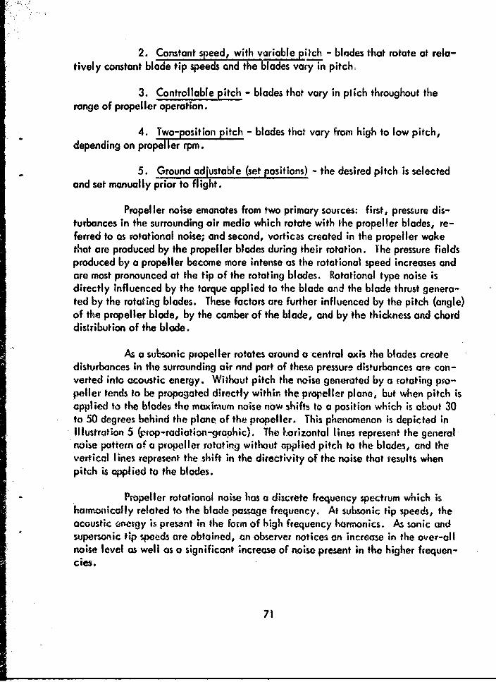
2. Constant speed, with vyriablepitch - blades that rotate at rela-tively constant blade tip speeds and the blades vary in pitch,
3. Controllable pitch - blades that vary in ptlich throughout therange of propeller operation.
4. Two-position eitch - blades that vary from high to low pitch,depending on propeller rpm.
5. Ground adjustable (set positions) - the desired pitch is selectedand set manually prior to flight.
Propeller noise emanates from two primary sources: first, pressure dis-turbances in the surrounding air media which rotate with the propeller blades, re-ferred to as rotational noise; and second, vortices created in the propeller wakethat are produced by the propeller blades during their rotation. The pressure fieldsproduced by a propeller become more intense as the rotational speed increases andare most pronounced at the tip of the rotating blades. Rotational type noise isdirectly influenced by the torque applied to the blade and the blade thrust genera-ted by the rotating blades. These factors are further influenced by the pitch (angle)of the propeller blade, by the comber of the blade, and by the thickness and chorddistribution of the blade.
As a subsonic propeller rotates around a central axis the blades createdisturbances in the surrounding air nnd part of these pressure disturbances are con-verted into acoustic energy. Without pitch the noise generated by a rotating pro-peller tends to be propagated directly within the propeller plane, but when pitch isapplied to the blades the maximum noise now shifts to a position which is aLout 30to 50 degrees behind the plane of the propeller. This phenomenon is depicted inIllustration 5 (,rop-rediation-graphic). The korizontal lines represent the generalnoise pattern of a propeller rotating without applied pitch to the blades, and thevertical lines represent the shift in the directivity of the noise that results whenpitch is applied to the blades.
Propeller rotational noise has a discrete frequency spectrum which isharmonically related to the blade passage frequency. At subsonic tip speeds, theacoustic energy is presant in the form of high frequency harmonics. As sonic andsupersonic tip speeds are obtained, an observer notices an increase in the over-allnoise level as well as a significant increase of noise present in the higher frequen-cies.
71

900650 115°
0 0o 180
% . %
Illus. 5 %irectivity of Noise With and Without Propeller Pitch
As propeller tips rotate at spersonk weeds, the aoustic "nergy presentin higher hommonncs becomes more intense than the acoustic energy generated by thefundamental, and higher frequency nois. components are mast notiabke in theacoustic field generated by a supersnic propeller. Even though the higher h••-monics contain more intense noise than the fun•amental, the peak frequency rangeis still contained within frequencies below 1,200 cps.
As already mentioned, vortices gnerated by u preller prc•duce a roisein higher frequency ranges than do rotationol dis nces. The frequency spectruinof the noise generated by vortex disturb•nces is more or les continuous in notureand tends to shift into progressively higher frequency ranges "--4th increoses in p'o-poller tip speeds. In general, voriex noise is usually most evident at positiont lo--coted in front of the blade. The acoistic energy of vortex noise is related to therelative pressure resistance of the aerodynoaic flow (or pos.age) encountered bythe propeller. Under certain conditions when the propeller is spinning ot low tip
72

speeds, the noise resulting from vortex formations may exceed the rotational noise.At high propeller tip speeds the vortex noise is evident only at higher frequencies.This, when a propeller is rotating at high tip speeds, the dominant noise is createdby intense pressure disturbances resulting from the rotating blades. This dcinw'ntnoise is representative of rotational noise and is most prominent in the lower fre-quency ranges. Vortex noise, although present, is less intense than rotational noisebut may be evident in the higher frequencies.
Propeller tip velocity has a direct influence on the noise pattern genera-ted by the propeller. Illustration 6 depicts the directivity characteristics of thenoise produced by a subsonic and supersonic propeller. At subsonic tip speeds thenoise generated by the propeller is most intense at positions just aft of the propellerplane, usually between 100 &o 140 degrees from the front of the propeller. Thedirectional pattern changes when propeller tip speeds approach and exceed the speedof sound. At supersonic tip speeds the directivity pattern of the maximum noiseshifts to a position directly in IOne with the propeller plane and as the blade tipsrotate at, or near, the speed of sound (Mach 1.0) the noise generated by the propel-ler becomes wore intense, resulting from increases in the magnitude of both therotational and vortex noise components. The increased intensity of the vortex androtationnl noise ;s directly related to the increased propeller tip speeds. Also, whenthe propeller tips rotate at, or exceed, the speed of sound there is a noticeable in-crease in the noise generated within the higher frequencies. Very high propellerblade tip speeds are usually associated with propeller systems powered by turboimop
"UPERSONIC ISNICo /j0/S~~-2/
-4-6 /I'
S" ~-14
-16...260" 40 60 80 100e 1226° 140° ,60° Is0°Illus. 6 Directivity of Noise Produced by Subsonic and Supersonic Propellers
73

power plants. Increasing propeller tip speeds beyond the supersonic range do notcause a further shift in the directivity pattern of maximum noise generated by thepropeller blodes, but merely restrict the general spread or angle of the maximumacoustic energy distribution.
Over-all noise levels generated by superz...; propellers are of greaoerconcern than equally intense noises generated by a subsonic propeller. In general,supersonic propellers not only cause an increase in the noise emonating from thepropeller, but also produce an increase in the intensity of the higher frequenciesab• the fundamental. This increase in the intensity of the noise spectrum abovethe fundamental (which is usually below 150 cps) results in a noise field that is ofgreater concern than that below it. Also, the noise created by supersonic propel-lers that produce higher frequencies are more efficient maskers of speech communi-cation.
Torque, or the amournt of twisting powetr applied to a propeller shaft,has a direct and significant influence on the noise generated by a propeller. Apropeller rotating at a constant rpm will produce more noise when torque is in-creased. In fact, the amount of torque applied to a given propeller or rotor systemis a more significant influence on the noise produced by the propeller than the rpmof the propeller itself. Most of our present day power plants, especially those usedto power large fixed- and rotary-wing aircraft, maintain a veiatively constant pro-peller shaft speed. When increased thrust is required from the propeller, the pro-peller rpm is maintained at th, •ome speed and the desired increases in thrust areobtained by the delivery of increased torque. The most common expression of torqueis in pounds per square inch (psi). During a static run-up, as torque increases, theintensity of the propeller noise is most dominant at locations behind the propellerplone.
When torque is maintained at a constant value, the thrust provided by apropeller decreases as airspeed increases. Initially, the total noise generated de-creases with increasing forward velocity of the vehicle , but at a higher velocitythe effect of motion on the generated noise actualIy produces on increase in thetotal noisegenerated within the propeller plere area.
Generally, the highest torque rpplications cue associated with augmentedthrust. Augmented thrust from both reciprocating atid gas-turbIne (tuboprop) engines
is obtained by the use of fluid-injection (sometimes referred to as water-injection).During augmented power the engine can develop more torque power which resultsin increased thrust. The increased torque, when applied to the propeller shaft, re-suits in an increase io tive propeller noise (primarily due to the increased pitch ofthe blade systems).
74

Bla'ae thickness, which varies considerably from one type of propellersystem to another, apparently has only a slight influence on the intensity of the noiseproduced by a propeller; however, there are numerous other factors related to c pro-peller system that may have a direct or indirect influence on the frequency spectraof the noise. For ,nstcnce, although the width of the propeller b6des does not causea significant change in the frequency of the fundamental, 'he intensity distributionof the higher Frequency harmonics may be altered. This phenomenon is related tocertain operational characteristics. Usually, the greater the width of a propellerblade, the slower will be the speed of rotation required to produce a desired thrust.As a result, noise variations produced by a propeller system with wide blades is di-rectly influenced by the total thrust derived fromi the blades, the amount of torqueapplied to 1ne blades, and the directional properties of tha acousiic disturbancesgenerated by the b':.des.
Considerable research has been conducted on increasing and decreasingthe number of blades within a propeller system. All factors being equal, the addi-tion of more blades to a propeller system will result in a decrease in the over-allnoise. By increasing the number of blades in a particular propeller system, thegeneral effect is to cancel out all higher frequency harmonics except those directlyrelated to multiples of the number of blades. The number of blades in a prcpellersystem, when evalr' -riainst the frequency of times each blade in the systemposses a fixed point, . ,rmines the fundamental frequency of the noise generatedby a propeller.
At a constant propeller rpn,, the greater the number of propeller blades,the higher will be the blade passage frequency, and the fewer the number of blades,the lower will be the frequency of blade passage. For instance, a th.ee-bladed pro-peller rotating at 1,000 rpm will have a blade passage of 50 times per second andthis a fundamental frequency of 50 cycles per second. The fundamental frequency,as well as the harmonics generated by the propeller., are directly influenced by thefrequency of the occurrence of each of the disturbing mechanisms - the individualpropeller blades. When rotating at low tip speed the fundamental is the most pro-nounced of the frequency components generated by the propeller, but as propellertips approach the speed of sound the harmonics increase in magnitude until theyreacih a point where they are more intense than the fundamental. The most intensefrequency component produced by a supersnic propeller is usually found to be adirect multiple of the blade passoge frequency.
In general, increasing the number of blades (usually not exceeding four)allows an increase in the distribution of horsepower per blade. Ir several instances,especially from iurboprop propeller systems, increasing the number of blades from
75

three to four allowed the following modifications and changes to be made withoutpenalizing total performance: 1) the total diameter of the propeller was reduced,which also resulted in a greater fuselage to propeller tip clearance, and 2) the pro-"peller tip speed could be reduced, resulting in less intense propeller noise.
A frequency shift of the fundamental as well as the higher frequency har-monics is produced by increasing the number of blades in the propeller system. Forthis reason, a four-blade propeller will generate a somewhat more intense higherfrequency spectrum than will a three- or two-blade propeller.
The application of contrarotating propellers has been investigated, andalthough greater potential blade propulsion energy is represented, the aerodynamicdisturbances created by a one-blade system apparently interact on the second bladesystem. Investigations determined that utilizing contrarotating propeller systemsresulted in a significant increase, rather than a decrease, in the noise. In a similarmanner the disruption or distortion of airflow impinging on the blades of a rotatingpropeller may result in a significant increase in the noise and vibration producedby the propeller. This phenomenon is usually associated with propellers located aftof the fuselage or wing areas, commonly referred to as "pusher-type" propeller sys-tems. The increase in noise and vibration results from disruptions in the atmosphericmedium through which the propeller blades must pass. As the more or less evenly
distributed atmosphere is separated by leading structures of the aircraft, areas ofhigh and low pressure are created, thus producing a distortion of otherwise equallydistributed atmosphere. If a propeller is mounted aft of the main fuselage or wing,the blades receive unevenly applied pressure loadings from the disrupted and unevenairflow created by the passage of the aircraft through the atmosphere. This disruptedairflow impinging on the blades may create a situation in which the alternatingstresses encountered by the blades result in a misalignment of the plane of rotation.If this occurs the propeller creates movements in yaw around the axis of the propellershaft. This type of phenomenon is not commonly encountered by current Army air-craft, but designs now under study for future .'TOL and STOL aircraft powered bypusher-type propellers may result in such applications. Of course the significanceof such propeller matings may be dictated by several variables, but, in general, thispartic.ular type of propeller system can be expected to generate more noise and vi-bration than a similar power plant and propeller system that is mounted forward ofthe foselage and wing areas.
The type, size, and number of blades in the propeller, the type of powerplant, the relative degree of aerodynamic disturbances created before the atmosphereimpingc upon the blades of the propeller, and operational factors may have a directinfluence on the degree of noise and vibration crealed by such aircraft-to-powerplant matings.
76

Unique Turboprop Propellers. Propeller systems mated to turboproppower plants must meet rigid requirements. The propellers must possess good struc-tural integrity, be almost perfectly balanced, and the blades must be accuratelyand reliably controlled throughout all phases of pitch change.
Turboprop propellers have unique operational features that directly in-fluence the noise they produce:
1. Since the propellers rotate at very high blade tip speeds, intensenoise is generated relative to the magnitude of rotational disturbances they create.
2. Because of high blade tip speed, the angle of maximum noiseradiation is usually located almost directly in the propeller plane.
3. Due to the increased frequency of blade tip passage, turboproppropellers generate harmonics that are. usually more intense than the fundamental.
4. Since most turboprop propellers rotate at a relatively constantspeed, changes in blade pitch and torque may result in significant alterations inthe intensity, frequency distribution, and acoustic radiation patterns of the propel-ler noise.
5. To achieve the best possible braking action during landing roll,reversed pitch is accomplished at h!igh torque values. Rather intense noise is gen-erated during this maneuver due to high propeller tip speeds and torque values.
Since turboprop propellers rotate at higher rpm than propellers poweredby re..-rocating engnes, there are less structurally induced low frequency vibra-tio;ýs •e to imbalances and misalignments that cause yaw in the central axis of thepropeller shaft. Needless to say, if yaw in propeller rotation does occur, exces-sive vibrations may result due to the very high propeller shaft rpm.
Turboprop propeller syste,. " possess very good thrust reverse character-istics. As the propellers of aircraft are reversed in pitch there is usually a notice-able increase in noise produced by the propellers. The noise produced during re-
versed pitch is of short duration and is most dominant in the frequency ranges belowabout 600 cps. The magnitude of the noise resulting from propeller reversal is de-pendent on the angle of pitch attained durina -ýve'-.nl, the amount of torque ap-plied, the rpm of the propeller, and the basic aerodainmic features of the bladesof the propeller. Most propeller reversals do not invert blade pitcn more than aminus eight to ten degrees. Since the thrust of the F "opellers is reversed, the di-rectional characteristics of the noise are swiftly altered. During the initial phase
77
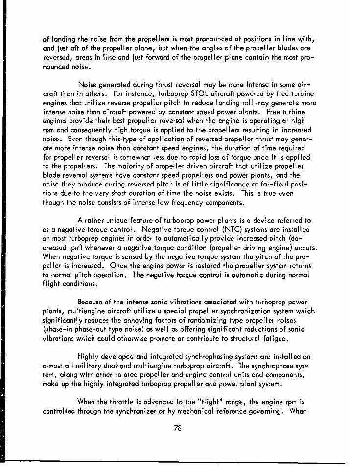
of landing the noise from the propellers is most pronounced at positions in line with,and just aft of the propeller plane, but when the angles of the propeller blades arereversed, areas in line and just forward of the propeller plane contain the most pro-nounced noise.
Noise generated during thrust reversal may be more intense in some air-craft than in others. For instance, turboprop STOL aircraft powered by free turbineengines that utilize reverse propeller pitch to reduce landing roll may generate moreintense noise than aircraft powered by constant speed power plants. Free turbineengines provide their best propeller reversal when the engine is operating at highrpm and consequently high torque is applied to the propellers resulting in increasednoise. Even though this type of application of reversed propeller thrust may gener-ate more intense noise than constant speed engines, the duration of time requiredfor propeller reversal is somewhat less due to rapid loss of torque once it is appliedto the propellers. The majority of propeller driven aircraft that utilize propellerblade reversal systems have constant speed propellers and power plants, and thenoise they produce during reversed pitch is of little significance at far-field posi-tions due to the very short duration of time the noise exists. This is true eventhough the noise consists of intense low frequency components.
A rather urique feature of turboprop power plants is a device referred toas a negative torque control. Negative torque control (NTC) systems are installedon most turboprop engines in order to automatically provide increased pitch (de-creased rpm) whenever a negative torque condition (propeller driving engine) occurs.When negative torque is sensed by the negative torque system the pitch of the pro-peller is increased. Once the engine power is restored the propeller system returnsto normal pitch operation. The negative torque controi is automatic during normalflight conditions.
Because of the intense sonic vibrations associated with turboprop powerplants, multiengine aircraft utilize a special propeller synchronization system whichsignificantly reduces the annoying factors of randomizing type propeller noises(phase-in phase-out type noise) as well as offering significant reductions of sonicvibrations which could otherwise promote or contribute to structural fatigue.
Highly developed and integrated synchrophasing systems are installed onalmost all military dual-and multiengine turboprop aircraft. The synchrophose sys-tem, along with other related propeller and engine control units and components,make up the highly integrated turboprop propeller arid power plant system.
When the throttle is advanced to the "flight" range, the engine rpm iscontrolled through the synchronizer or by mechanical reference governing. When
78

operating in the lower rpm "ground" throttle range, the propeller blade angle iscontrolled through a coordinator-potentiometer mounted on the engine and actuatedby the fuel control unit. Propeller control is proportional to the throttle settingthrough the ground control range to a full reverse blade angle control of minus 9.2degrees.
The synchrophasing operates through a basic synchrophaser system to main-tain propeller blade position in relation to the blades of the other propellers, i.e.,the blade tips of adjoining propellers do not pass the same relative point at the sametime. This system reduces harmonic vibrations, noise levels, and other associatedvibrations which could contribute to structural fatigue.
An acceleration stabilized propeller governor, located on the rear of thepropeller power unit, is provided to correct the blade angle of its respective propel-ler in order to maintain the desired engine speed during any normal flight attitude.Whenever the throttle is in the flight range the propeller governor controls the rpmof its respective engine either electrically (through the propeller synchronizer) ormechanically (through an individual mechanical reference governor).
An electrically powered propeller synchronizer provides a controlledelectrical reference signal which drives a propeller governor reference motor oneach engine at the same speed, thus achieving synchronized speed operation of allengines. The propeller synchronizer is energized during engine operation wheneverthe throttles are in the "flight" range and the propeller synchronizer system is en-gaged (selected by the pilot). With the synchronizer engaged, synchronous propel-ler shaft operation at any engine speed between the range of 94.5 to 100 per centrpm will result. During synchronizer operation the speed of all engines will besynchronized to the speed of the engine with the most forward throttle position. Inthe event malfunction causes the rpm of the engine to become either less than 92.5per cent rpm or greater than 103 per cent rpm, control of that engine will automat-ically be chanced fom the propeller synchronizer to its mechanical reference gov-ernor and will be maintained at 97.9 per cent rpm. If the throttle of an enginewhose speed is being controlled by its mechanical reference governor is advancedforward of the other three throttles, the speed of the synchronizer-control led engineswill increase. Under these conditions, the torque of the mechanical reference gov-ernor controlled engine will increase as its throttle is advanced, but its rpm will re-main at 9-.9 per cent.
Figure 9 illustrates the general influence increased propeller rpm mayhave on the noise emanating from propeller disturbances. The noise measurementswere taken at a position directly in front of the propeller. The noise was producedby a horizontally opposed six-cylinder Continental 0470 engine with a fixed pitch,
79

FREQUENCY BY OCTAVE-BANDS
OAL 37.5 75 150 300 600 1200 2400 480075 150 300 600 1200 2400 4800 9600
120 . - - -
0
1190C-)
0
C,,
80 ".. .
S2 70z • 1700 rpm .. :
0 2100 rpm
60 -
Fig. 9 0470 Engine Test Noise Measured at a Distanceof 57'2 Directly in Front of the Engine
two-blade propeller of 7.5 feet diameter. The measurements were accomplished
while the engine was installed on an open test bed. Since the propeller has fixed
blade pitch, increased rpm does not create a .Hange in propeller pitch. Also, the
presence of higher frequency energy is evident when the propeller blade tips in-
crease in velocity. With the engine operating at 1,700 rpm the propeller rotates
at a blade tip velocity of approximately 668 feet per second (0.60 Mach), and at
2, 100 rpm propeller tip velocity increases to approximatey 824.6 feet per second
(0.74 Mach). Since the propeller blade remains at the some pitch the increased
propeller tip speeds clearly account for the generation of vortex as well as rotational
noise. Once again, the total spectra shows a more wide-spread alteration Ce the
noise than the differences in the over-all noise level reveal.
Figure 10 shows noise emanating from the same engine during similar
operations, but these plottings represent the noise propagated directly in the
80

FREQUENCY BY OCTAVE-BANDS
OAL 37.5 75 150 300 600 1200 2400 480075 150 300 600 1200 2400 4800 9600
130 - - .
0
1- i -i -i - - -
120 ,, , ..
S: -110 - -
z 90
z ~~~In Pao plane, 6' distance : - :.S80E • ~~1700 rpm - " :
0 2100 rpm- "70
Fig. 10 0470 Engine Test Noise Measured at a Distanceof 6' Directly in the Propeller Plane
propeller plane. The fundamental of blade passage becomes somewhat more import-ant since the noise generated directly in the prope!ler plane is directly related tothe number of blade tip passes that occur per second. At 1,700 rpm the blade pas-sage is 56.5 times per second, and at 2, 100 rmm the frequency of passage increasesto 70.7 times per second. The noise increases noted at the side of the propellerplane are representative of the rotational noise, most evident at frequencies belowGbout 300 cps, and higher frequency harmonics that are related to the fundamentalfrequency that is quite annoying to the majority of people. Of course, two-bladepropeller systems are generally louder than a three- or four-blade system operatingat equal power. Generally, two-blade type noise is more annoying because thetime duration between individual blade disturbances is increased to a value wherethe human ear perceives the noise, not as a continuous steady type noise, butrather somewhat like a slapping and pulsating noise.
81

General observations of noise created by small reciprocating enginepropellers indicate that the noise generated by small, high speed, fixed pitch pro-pellers contains a wider and more evenly distributed frequency range than that com-monly associated with medium size engine-propeller systems. When referring to apropeller system, the use of the term "constant speed" is probably often misunder-stood. For the most part, a distinction should be made, especially between recip-rocating and turboprop powered constant speed propellers. First of all, the constantspeed type propeller used on reciprocating engine aircraft usually operates duringtake-off at much higher speeds than during normal flight, and one should be carefulnot to erroneously assume that the term "constant speed" propeller means that thepropeller will only operate at a constant rpm. A good example of noise generatedby a constant speed propeller system during take-off and climb is the U-8D aircraft.
Figure I1 illustrates o:n increase of the propeller noise generated withina U-8D aircraft during two phases of high engine and rpm power settings. The U-8D is powered by two Lycoming 0-480 engines that are fitted with three-blade con-stant speed, hydraulic controlled, and full feathering type propellers. Once thedesired altitude has been achieved and the throttles retarded to normal cruise power,the automatic propeller power control system is engaged. The noise illustrated hereis produced almost entliely by rotational noise. During take-off the propeller tipsrotate at approximately 880.0 feet per second (0.788 Mach). As the engine rpmincreased, the propeller tip velocity likewise increased resulting in increased noise.The noise produced by the propellers during take-off resulted in an over-all increasein the intensity of the noise, as well as a broadening of the noise spectrum. Onefactor contributing to the broadening of the higher frequency range during increasedpropeller rpm is the shift of ti;j blade passage frequency into higher ranges. Forinstance, the fundamental blade passage during take-off is 109. 1. After power hasbeen reduced the width of the spectrum of the noise narrows and the over-all noiselevel decreases. During climb the reduced engine power and propeller shaft rpmshifted the propeller tip blade speeds to 776.5 feet per second (0.695 Mach) andalso shifted the frequency of fundamental blade passage to 96.3 times per second.
Intense propeller noise is commonly associated with take-off operationsd4e to the requirements for increased engine and aircraft performance. The propel-ler becomes a sign'ficant noise generator primarily because of increased propellertip speeds. As the rpm is increased, thus offering greater power, the propellersrotate tit faster speeds and by taking smaller, but foster, amounts of the air, in-creased take-off performance is achieved. Normally, after rpm is reduced, theblades of the propeller system increaste in pitch (angle) and take larger displacementsof the air. At constant .pm, the higher the altitude, the greater will be the pitch
.required ef the blades.
82

FREQUENCY BY OCTAVE-BANDS
OAL 37.5 75 160 300 600 1200 2400 480075 150 300 600 1200 2400 4800 9600
120
Ito
S103
70 TO..340GRPM, 4511MP0 Climb, 3000 RP"" 40" MP
Fig. 11I Internal Noise of U-811 Aircraft Measured atHead Level Between Pilot Stations
Figure 12 shows the characteristic noise distribution of an OV- I B meas-ured at 45, 90, and 135 degrees at a distance of -50 feet. The nsoise Is representa-tive of only one engine and tweasure-ments were. completed with the propeller rota-ting at a blade tip speed of 0. 733. 1 feet per, second (0.656 Mach) .- a bladepossage frequency of 70 times per second. The blades were also operating at ahigh pitch. The noise plottinns Insdicate only slight change in over-all levels, butrather sigSnificant differences in spectra were found. In front of the propeller plaile
* (45 degrees) the noise spectrum was relatively fiat. In the plane of the propellerthe lower frequency range increases and the noise is not as evenly d~stri'butedthrough the frequency spectra. Aft of the propeller plane (135 degrees) the noise
* emanating from the propelleý5 i4 the most intense of the three positions due to thecomnbination of blade tip speed and thrust (torque) which combine to create a relo-
* tively intense, low frequencý type noise.
83

FREQUENCY BY OCTAVE-BANDSOAL 37.5 75 ISO 300 600 1200 2400 4800
7S 150 300 600 1200 2400 4800 9600
12 * , --) -. - --
Sli
C... . ...
z 0
° I0
z 90 degees
A 135 degrees "60
Fig. 12 External Noise of OV•-tB Aircraft During GroundOperations, Propeller Check, 83%, 1400 RPM
Figure 13 shows differences in the noise produced ky the same aircraftSat the some pnositions w5 distance, but during these measrements the propeller
I rpm was decreased by 199.0 feet per second (equo| to a decrease of 0. 178 Much)and the blade pitch was also decreased. Since the power plant is a free turbine
Ftype engine, .propeller rna is decreasd the engine rpm is also decreased. De-
creased propeller tip speed and blade thrust significantly decreased the rotationalinoise produced by the propeller and, as a result, at a position of 45 degrees, the
presence of engine noise is quite evident in the 150 to 300 cps frequency range.
At a location with;n the propeller plane (90 degreies) the most dominant noise isrelated to the frequency of blade passage, which is 51.0 times per second, and at135 degrees the most dloinant noise emanties from the aerodynamic displacementscreated by the propeller blades, -and is most pronounced in the 75 to 150 cps bond.
84

FREQUENCY BY OCTAVE-BANDSOAL 37.5 75 150 300 600 1200 2400 4800
75 150 300 600 1200 2400 4800 9600
1100
90
800
70
400
>41
II0 45-egee
50 E -.-] -1 _4-
F..... 13 Exera .-= of O-- -1- AicatU.igGonOprtos Mesue at 50 .Ditace Flgh Ue, 60
C.)
o the propeller 45 degrees T a- "a F asS~~0 90 degrees " :
Z• 135 dejrees - -- - -
Fig. 13 External Noeie of OV-1 B Aircraft p )uring GroundOperations, Measured at 5t0 Distance, eight rdie, 6w a RPM
Si Figure 14 alsi duw the effect of propelpr pinch on the noise generooft-by the propeller. In this instance the propeller noise of a U-pA aircrft sr in meas-ured at a distance of twelve feet directly under the wing and at a position cust eftof the propeller (45 degrees). The aircraft was located on sod during the measure-ments a•nd wind blast was negligible. The noise plottings in the illustration show a
Sgeneral increase int the noise throughout the frequency spectrum, with about a sixdb increase in intensity due to o change of blade pitch. Increasing the pitch of the
.* blade required considerably mote torque, and since the blade is a c.;;',,tont speed* type, the increases in rpm are negligible. Note that the monifold pressure increased
• . from 17.5 to 27 inches du~ring this operation, indicating a considerable increase in- applied torque to the propeller system duo to increase resistance generated by the
increased pitch of the propeller blades.
figure 15 gives examples of the noise genercaed in the prop.eller plaoie ofa CV-2B during take-off. Note the difference in the noise produced by the propellers
85

FREQUENCY BY OCTAVE-BANDSOAL 37.5 75 150 300 600 1200 2400 4800
75 150 300 600 1200 2400 4800 9600
9 10 100
S90
7 )
70 Left side, 12' -45°to rear of CL ofr -
* Low pitch, 1000RPM 11.5it MP0 High pitch, 1150RPM, 27" MP
Fig. 14 External Noise of U-1A Aircraft During Ground Operations
during take-off with the engines operating at 2,700 rpm and 50 inches of manifoldpressure, and the noise produced when the engines are reduced in power to 2,000rpm and 32 inches of manifold pressure. The most significant noise is propogatedin the lower ffequency ranges and tends to fall off continuously with increasingfrequency.
Most aircraft powered by reciprocoting engine-propeller systems producevibrations that are the direct result of imbalances of the propeller. If a propelleris out of ollgnment, or imbalanced, considerable vibration may result within theengine and, in turn, the structures of the aircraft. Propellers that are misalignedor niitbalanced may generate structurally induced vibrations due to distuirbances inyaw as they rotate around a central axis. For instance, if o propeller is imbolancedas it rotates around a central oxis, it will generate inbolonced torque actions whichcause the propeller shaft to move in positions of yaw. This phenomenon, added toother Wbaances within the engine itself, .mnay gerwrote significant vibrations.
86
FREQUENCY BY OCTAVE-BANDSOAL 37.5 75 IS0 300 600 1200 2400 4800
75 ISO 300 600 1200 2400 4800 9600140 . .....
S - T. 0., 2700 RPM, 50" MP0 130 A- 0 NRC, 2000 RPM, 32" MP, 140 KIAS
0
9 120 ..0
I,,..• ... : "
100 " ""."
90,-.. . - -- \
Fi9 . 15 Internal Noise of CV-2B Aircraft During Flight, Measured atHead Level in the Left Seat, Directly in the Propeller Plane
Propellers may also generate vibrations of the aircraft structure by tiedynamic pressures exerted by the rotating propeller blades. The pressures generatedby the propeller impinge on the side of thd fuseloge and wings, thus setting up oform of induced vibration. This type of vibration is usuolly found to be most intensein the propeller plane area of the vehicle.
Figure 16 illustrtes the magnitude of change within various frequencieswhich con result due to propeller rpm differences. The differences shown here weremeasured between the pilots of a U-81) twin-engine aircraft during normal cruise.The rpm synchronization was adjusted monutwlly until t.n "ideal"' synchronizotion wasobtained. The intensity versus frequvd.-y ranges are representative of 30-secondintervals. The total radiated acoustic energy of a proceller increaes with propeller
tip speeds. The rndiated energy oa subsonic propellers mcV be less than one-one
87

FREQUENCY BY OCTAVE-BANDSOAL 37.5 75 150 300 600 1200 2400 48U0
75 150 300 600 1200 2400 4800 9600110 - --
o 100 - -
9 0
70° .
60. ...
10 -- •
Fig. 16 Internal Noise of U-81D Aircraft During Flight at Normal Cruise,Measured Between the Pilots at Head Le':1d, Propellers in Synchronization
thousandth of one per cent of the propeller power, whereas for a supersonic propel-"let the acoustic energy may be several per cent of the total power of the propeller.
The frequency characteristics of propeller noise are directly related tothe blade page frequency. For all propellers, subsonic and supersonic, the low-est frequency component is determined by the fundamental blade pasage frequency,end all other frequency peaks are multiples of the fundamental. Propellers rotatinge• subsonic blade tip speeds generate the most intense noise element at the funda-mental, ond supernic propellers generate their most intense noise component in thehrimtonics. The noise spectra generated ýy sulbso.ic propellers may also possessbroad peaks in the frequency range above 1,000 cps. This increase is due to shed-ding of boundary loyor disturbances and vortices from the blades, and is commonlyreferred to as vortex noise. Supersonic propellers generate intense noise elements
* in the higher frequncdes. The major noise component is associated with rotationalfactors such as blade displacement and aerodynamic loodings.
88

The location of the observer relative to the direction of propeller rota-tion may have a definite bearing on the noise received at a given position. Duringrotation (ground level) the sound field may be considerably affected by inducedvariations in the airflow or by the presence of a surface (a wing, for example). Ingeneral, the approaching side of a blade produces more intense sound pressure dis-placements than the retreating side.
Main Rotor Systems. Rotor noise is much more involved and difficult toexplain than simple propeller noise. The components which generate and modifyrotor noise nre complex and slight operational changes result in rather significantchanges in the noise.
Noise, resulting from rotor(s), is produced by aerodynamic disturbancesor direct structural (mechanical) vibrations, or both. In most instances, the noiseemanating from aerodynamic disturbances is the most significant.
Two components comprise the bulk of the noise associated with propellersand rotors - rotational and vortex noise. Rotational noise, as the name implies, isdirectly related to disturbanc.s generated by the rot.r blHes as they rotate. Thisnoise is directly related to th.e blade passage frequency and is associated with .hetotal thrust and torque developed by the rotor blades. The frequency of tne noisegenerated by the rotors is multiple and is determined by the frequen--y of the bladepassage. If blade passage frequency Zs low, the 4,wer frequency roise produwed bythe rotor is inaudible.
Rotational noise is associated with several cerodynamir forues. Forcesof drag and lift are created when a blade po.sses thro r.g an elastic Mdium, Theseforces cause disturbances of the air medium with both positive and negptive altera-tions, which arv transmitted as presstre weves at frequencies determined by the airloadiig blade passoge and force varoation. At a fixed position near the rotors, thefundamental frequency of these pressure waves corresponds to the blade passage fre-quency.
It is generally accepted that rotational noise is primarily a function ofthe total thrust produced by the blade of o rotor or propeller ýyttem. T hus, if" thenumber of blades is increased, the total intensity of the noise is reduced,
At slow rotot tip speeds the main rotor rotational noise s the dominantnohs,. As tip speeds increase, #lie noise present in ths higher frequency range be-comes evident. The highar frequency noise is the product of vortex noise producedby the main rotors and anti-torque rotor rotational noise. In some instancet, highspeed gear trc•sfer systems may generate high frequency noise.
89

The frequency components of rotational noise are easily identified asmultiples of the blade passage frequency. Since rotational noise is directly relatedto blade passage frequency, this noise contains discrete frequency components. Toaccurately define these components one must acquire a narrow-bond noise analysis.Blade passage frequency is high, and since the discrete frequency components aremultiples of blade passage, several discrete components may be present in a singleoctave band measurement. For this reason, the sound pressure level (SPI) readingsobtained by octave bond analysis do not indicate or define the number or magnitudeof the individual discrete frequency components present in a given octave.
The blades of a rotating rotor system produce vortices which take theform of audible noise, called vortex noise. As a blade rotates at slow tip speeds,the directivity of the noise is in the form of concentric spheres as a function of localstresses on the medium. At high tip speeds a distortion of vortex noise pattern occurs.High blade speed causes the directivity pattern of the noise to elongate from a con-centric sphere shape. The distribution of the maximum noise has moved to a positionjust forward, above, and below the advancing blade.
Vortex ro.ie niova. with the rotating blade, and as a result, vortex. icisemensired by the ..bserver has undergone modr' 2tions due tn- the blade passage fre-qv-ncy. "Vortex noise froio rokorz contains frequencies that are directly related tothe blado tip speed. The directivity puttern of vortax n~oise rotate,. with tuie ro~otingblade and *s consequently niodJoted by the frequency of blade passage.
In many instnnces, even though the rotatto0nol noise produced by therc-tors is "~re intense than that generated by other noise cciriponents, it !s sub jec-tively less nw~cea½!e becouse t+e fundamental and lower hatrv)thics are not withinthe audi~le range of man's hearing. Thus, in the mnaf-rity of cases,. the anti-torquerotational noise and the vortex noise of the main rotor is sutbet.Ively more notice-able.
Vortex noise results from stre-ss, acting on the surrounding air throoghwhicN the blcee pmse.4. Vortex noise is distr~buted in the higher freque~~cy raingesand is influenced by the aerodynrairk flow of air over the blade and also by thefrontal area of the blade. Vortex noise produced 6y main irotor systemrrs is the mostsi~tiifi.ont singl #-iefctor associated with the various rotor noise compnens.
The influence of thrust on iwo-blade- rotor systems produces more noise+anr for th~ree-blade rotor systems when operating at lower blade loadings. Ge-ner-alty, as blade loading incretise: the -siqnificance of voriex noise increases and thesign'.ficance of roatottno! noise decreases3. Essentially, a two- or three-blade rotorsystem, at equal Icverong efficiency, produces approximately the same amount of
90
vortex noise, but the rotational noise level of the three-blade rotor system is appTe-ciably lower than for a two-blade rotor system. These two conditions are basicallytrue when equal thrust is being produced by the rotor-blade system.
Since the noise from rotor systems is generated by the blades, the patternof the noise rotates with the blades. The maximum noise radiation is found at posi-tions opposite the direction of thrust and at angles of about 30 degrees from thecenter line axis of the blade.
Various aerodynamic parameters, including number of blades, blade tipspeed, thrust, and blade loading determine the contribution of rotational and vortexnoises to the over-all noise generated by main and anti-torque rotors. Of thesevarious parameters, blade tip speed is the most significant. In most instances, areduction in blade tip speed results in a more significant reduction in the over-all* .oise than any other single component.
Increased rotational and vortex noise results from main rotor thrust in-creases. Usually, two-blade rotors hove higher blade loadings than three-, four-,or five-blade rotors. Rotational noise may remain about the same when going froma two- to a three-blade rotor, but vortex noise will usually be more dominant fromrotors with fewer number of blades. Since vortex noise is directly dependent onblade tip speeds, the greater the number of blades in a rotor system, the lower willbe the requirements for high blade tip speeds. In other words, a three-blade rotorsystem requires slower blade tip speeds than a two-blade rotor system in order toproduce an equal amount of total rotor thrust.
Both noise components, rotational and vortex, incre ae with blade tipspeed. However, rotational noise tends to make a greater change with increasesin blade tip speed than does the vortex noise. The significance of the noise sourcesvary depending on the size of the vehicle. Small helicopters with high speed rotorsproduce rotor noise that usually dominates the acotic energies generated by theanti-torque rotors.
A study of the noise chamacteristics of helicopter rotors at tip speeds be-tween 100 to 900 feet per second were conducted by Hubbard and Magliere 17 atthe Langley Helicopter Tower. Their investigations suggest that noise of full scalehelicopter rotors results mainly from conditions of unsteady flow. Results furtherindicate that both to speed and disc loadings have an important influence on noiseradiated from the rotors.
During rotor stall, sound pressure levels increased €t ill frequencies, butparticularly at the higher end of the spectrum. The evidence of FVubbard and
91

Magliere suggests that a highly peaked wave form exists due to possible Dopplereffects associated with high tip speed operation. At low or moderate tip speeds therotor is usually of secondary importance as a noise source, but can become a majorsource when other noise components have been reduced. At high tip speeds therotor may be the dominant noise source of a helicopter. During these investigationsnoises from other sources were minimized and thus the noise emanating from the rotorcould be evaluated more accurately. During tests it was noted that noise from therotor varied markedly as a function of the tip speeds and disc loadings. Disc load-ings were measured in pounds per square foot from a range of tip speeds from 300 to900 feet per second. In general, for a given value of disc loading, the lower over-all sound pressure levels were associated with lower tip speeds. Exceptions occurredwhen the rotor was stalled, in which case the over-all sound pressure level increasedto a marked degree. At any given tip speed a relatively large amount of noise isgenerated at low values of disc loadings. This operational condition corresponds toground run-up prior to increasing blade pitch for take-off. For the latter considera-tion each blade is operating in or near the wake of the preceding blade and thus maybe in a highly turbulent flow region.
Low and high blade angles or pitch show significant differences in the fre-quency and intensity of the noise produced by the rotors, particularly at higher fre-quencies. As disc loading increases close to stall conditions, sound pressure levelsat all frequencies increase, particularly in the higher frequency ranges. Investiga-tions of wave forms at different rotor tip speed show that the peaks occurred at fre-quencies of blade passage. One significant feature noted is that the peak is ac-companied by high frequency fluctuation just forward of the blade, and low fre-quency fluctuation just aft of the blade. Wave form analysis further suggests thatDoppler effects may play a significant role in the generation of these peaks. Thesepeaks may dominate at higher tip speed and particularly at low values of disc load-ing. The noise appears to be increased by turbulent air (similar to the situationwhen a blade rotates in or near the wake of a preceding blade).
Other factors that may contribute to the intensity of noise levels are thedegree, type, and condition of acoustic treatment; aging of the vehicle's primaryand secondary systems; condition of rotors (a defective or imbalanced rotor systemrny produce rather severe vibrations); and conditions of seals at windows, cargo,and escape hatches. In oddition, during ground and hover operations, such factorsas terrain features will influence the noise generated by the vehicle.
One of the various noises associated with helicopters is the acoustic phe-nomenon referred to as blade or rotor slapping. Blade slapping does not always occur,but when it does it is a significant and dominating noise generator. The relativesignificance of blade slapping is most pronounced in larger vehicles and is also noted
92

to be more significant in tandem-rotor helicopters than in single-rotor vehicles.Blade slapping noise is distinctly audible and is most pronounced in the lower fre-quency range, usually bel'ow 600 to 800 cps. The peak noise level resulting fromblade slapping is between 100 through 500 cps. The noise produced by blade slap-ping is very intense and, since it covers a broad frequency range, easily masks theless intense noises generated by other components.
During low flight speeds a probable cause of blade slapping is the rapidangle of attack changes which a blade experiences -is it encounters its own or theprevious blade's wake 9 . A possible increase in pres-,ure compressibility may in-crease the severity of the effect as the angle of attack changes. Abrupt changesin blade angle cause increased lift and consequently the trailing wake system isalso changed abruptly. These abrupt changes in wake lead to an impulse type noisewhich produces wide frequency distributions. Less severe angles of blade attack canalter the characteristics of the boundary layer on the blade and the vortex noise maybe reinforced at blade passage frequency. As a blade posses through trailing vor-tices the results of sudden force variations on the blade elements near the rotor tipcan produce rotor slapping noise.
Rotor slapping does not usually occur during a climb maneuver. Duringclimb the traveling vortices of the rotor blades are directed away from the blades.Whereas, during a partial power descent, when rotor slapping is quite common, therotors are moving through their own wake. During high speed flight the effect ofrotor wake is less pronounced and thus the slapping noise is probably not fhe productof rotor wake. Increased rotor speed, necessary for high speed flight, probablycauses shock waves to form on the advancing blade, while local shock waves mayexplain the rotor slapping that occurs during high speed fl ight 9 .
Blade slapping is more common in tandem-rotor helicopters during almostall phases of powered flight because of the trailing vortices that are present fromboth rotor systems. Twin two-bladed rotors in tandem c9nfiguration seem to have agreater tendency to produce blade slapping throughout various flight profiles. Re-search on the Bell HSL helicopter9 has shown that the sudden rise in the sound pres-sure level associated with blade slapping occurs periodically at the blade passagefrequency for a single rotor. Blade slapping, associated with the CH-47A, seemsto occur during most flight conditions9 . It is generally believed that blade slap-ping occurs as the oft rotor leaves the region of forward to aft rotor overlap. Sig-nificantly different noises may be generated by tandem or two-rotor systems duringcruise conditAiss due to the interaction between the two rotors (the disturbed airfrom the front rotors is trasm-itted to the rear rotor system). In hovering, there isapparently little interaction between the two rotor systems. Rotor slapping noiseof tandem rotor vehicles may be reduced by decreasing the total area of blade
93

overlap and by increasing vertical separation between the passage plane of therotors.
Generally, the total noise generated by rotors can be reduced by, first,reducing blade tip speeds. As mentioned, this factor alone will help reduce bothrotational and vortex noise. Second, providing greater thrust distribution throughthe rotor system. This can be achieved by simply increasing the number of rotorblades required to provide a given thrust. For instance, increasing the number ofblades in a rotor system from two to three would result in increased total thrust,and would generate less noise.
In a study of frequency modes that exist in rotor blades, Brooks andLeonard7 report that the natural frequencies of the rotor blades can be appreciablyaltered by varying the location of the blade hinges. With two properly locatedflapping hinges, blade designs are possible which eliminate or greatly reduce con-ditions of resonance between the blade and the natural frequencies of the harmonicsthat are air loaded.
In order to reduce the tip speeds of main rotor systems the blade areamust be increased. In many instances this may be accomplished by increasing thenumber of blades in the rotor system.
Anti-Torque Systems. The rotational noise generated by anti-torquerotors is usTaFly the most pronounced of the various noises generated by such systems.A critical look at the frequency spectrum of anti-torque rotor noise shows the pres-ence of discrete sound pressure levels at multiples of the blade passage frequency.
Subjectively, the noise produced by most anti-torque rotor systems islouder than either rotational or vortex noise components generated by the main rotor.However, tail rotor noise, especially from high speed anti-torque rotors, may besignificantly reduced.
The vortex noise produced by anti-torque rotors tends to increase with anincrease in the number of blades and with higher rotor tip speeds. When tip speedsexceed about 500 to 700 feet per second, vortex noise is less evident and rotationalnoise becomes dominant.
Several factors must be considered in order t,. reduce the total acousticenergies generated by the various noise components r '-o ••*rs with main andanti-torque rotor systems.
94

Noise generated by the main rotors is predominantly low frequency, andnoise generated by the anti-torque system is usually distributed within the higherfrequency ranges. Thus any method designed to reduce the total noise of a heli-copter with main and anti-torque rotor systems must consider both of these noisegenerators.
Generally, the noise associated with main rotor operations, dominantlydistributed within the low frequency range, is subjectively less annoying or irrita-ting than the higher frequency noise generated by high speed anti-torque rotor sys-tems. The difference in subjective response to these two different types of noise isdue to the psychophysiological response of the human auditory system. Noise fromanti-torque rotors is especially irritating and annoying if it contains narrow-bandfrequency components.
Intense noise associated with high speed anti-torque rotors can be reducedby simply increasing the number of blades in the anti-torque system. Increasing thenumber of blades allows a reduction in bowh rpm and diameter of the anti-torquerotor because, as the number of blades is increased, there is a greater distributionof horsepower per brade. Aircraft manufacturers seem to be generally aware of thisfactor, and future helicopters which utilize anti-torque rotor systems will probablyhave three to four blades.
The over-all noise of a helicopter varies for different modes of operation.During hover, the pressure disturbances resulting from the passage of the rotcr bladesore fairly constant, especially at locations near the center axis of the rotor. Slightvariations in pressure disturbances may occur due to directional or control -llterationsduring the hover maneuver, but disturbances are usually of little significance. Dur-ing forward flight the rotors create a variation of pressure disturbances due to asym-metrical loadings of air acting on the blades. In order to obtain and maintain for-ward flight the blades in the rotor system vary in pitch and angle of attack as theyrotate 360 degrees around a central axis. The variations of the mechanical move-ment of the blades create a variation in pressure displacement as the blades rotate.
Hover maneuvers require a greater amount of rotor torque than forwardflight. When a helicopter is hovering the power required to maintain a constantlift is greater than during forward flight. During forward flight the rotors requireless power or torque because the helicopter has obtained a certain amount of mo-mentum.
Increased torque requirements during a hover result in a greater demandon the power plant and this increased demand results in more intense noise emana-ting from the power plant. Generally, as torque from a power plant increases,
95

there is a greater amount of strain and stress applied to the components of the enginewhich delivers the shaft horsepower. As these components are receiving greater stressthe noise generating mechanisms of each component increase.
Illustration 7 (rotor thrust) depicts the basic directivity pattern of rotation-al type noise as the blade rotates around an axis. This type of noise pattern tends torotate with the rotating rotor blades. Illustration 8 (vortex) demonstrates the generalpattern of directivity assumed by vortex type noise. The directivity as shown is illus-trative of vortex noise distribution at low tip speeds. It is to be noted that vortexnoise emanates as concentric spheres as a direct result of local stresses, but at hightip speeds, as shown in Illustration 9 (high tip vortex) the concentric patterns becomedistorted. As tip speeds increase the general directivity pattern of the vortex noisetends to elongate the spheres and shift the upper end toward the direction of bladerotation. Since the vortex noise rotates with the rotor blades, the vortex noise meas-ured at this position has al ready been modulated by the blade passage frequency.
STHRUST
plane of rotation
Illus. 7 Directivity Pattern of Rotational Type Noise
96
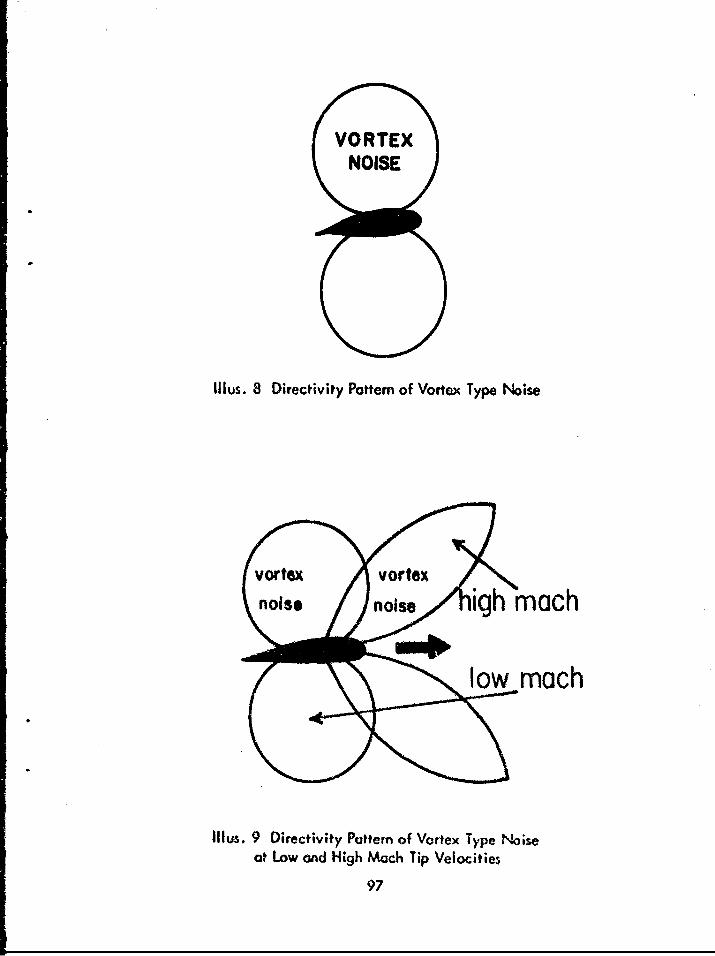
VORTEXNOISE
Illus. 8 Directivity Pattem of Vortex Type Noise
Vorexvortex
noise noise igh mach
l o~w roach
Illus. 9 Directivity Pottern of Vortex Type Noiseat Low and High Mach Tip Velocities
97

Figure 17 shows results of noise measurements mode at a distance of 50feet at various positions around a UH-19D helicopter during ground run-up. TheUH-19D has a single three-blade rotor with a diameter of 53.0 feet and a singletwo-blade anti-torque taiv rotor with a diameter of eight feet, nine inches. Themost intense noise was generated by the mcin rotors. During these noise measure-ments the rotors were rotating at a tip speed of 589.4 feet per second (0.528 Mach).The secondary noise between 1,200 and 4,800 cps containpd a combination of noiseelements genera*ed by the exhaust of the engine (nine-cylinder, radial Pratt andWhitney R1340) and the anti-torque tail rotor system.
FREQUENCY BY OCTAVE-BANDS
OAL 37.5 75 150 300 600 1200 2400 480075 IS0 300 600 1200 2400 4800 9600
120 -
W016 110 ere - -U/
100
0M
: 90
z 824"1 MP, 2400 RPM
z~ 7 0 90 degrees
0i 160 degreesT
Fig. 17 External Noise of UH-19D HelicopterMeasured at 50' Distance, Left Side
Figure 18 illustrates the noise generated by o CH-34C helicopter at var-ious positions at a distance of 50 feet. The general configuration of the CH-34Cis similor to that of the UH-19D, except the CH-34C has a main rotor that is threefeet greater in diameter and has four blades instead of three, the toil rotor has four
98

blades instead of two, and a nine-inch greater diameter. During these noise meas-urements the rotor had a blade tip speed of 513.1 feet per second (0.459 Mach).Noise emanating from the main rotors is predominate in tWe lower frequency range,and the noise emanating from the anti-torque rotor system was not pronounced dueto the noise reduction characteristics afforded by the increased number of blades.
FREQUENCY BY OCTAVE-BANDS
OAL 37.5 75 1SO 300 600 1200 2400 480075 150 300 600 1200 2400 4800 9600120 - - - • - .. . ..
110 - " _:I
Iý 00,. . .. ..
S90
z, LL.. side, 20CAil175 RPM, 20" MP• 70 0 135 degrees
-0o 90 degreesA 45 degrees
60 -... ... "• "
Fig. 18 External Noise of CH-34C Hel icopter Measured at 50' Distance
Figure 6, page 55, shows results of noise menasurements mode at variousloc.tions at a distance of 50 feet from a CH-37B helicopter during ground run-up.Durin, these measurements the main rotor had a blade tip speed of 799. 1 feet persecond 09.715 Mach) and the tail rotor had a blade tip speed of 681.7 feet persecond (0.610 Mach). Sound pressure levels at the side and rear of the vehiclewere most intense. In front of the aircraft the most dominant single noise elementwas from the main rotor, and at the side of the aircraft a combination of rotor andexhaust noise was evident. At the 135 degree location three noise generators werequite pronounced. The lower frequency noise was generated 6v 'he main rotor and
99
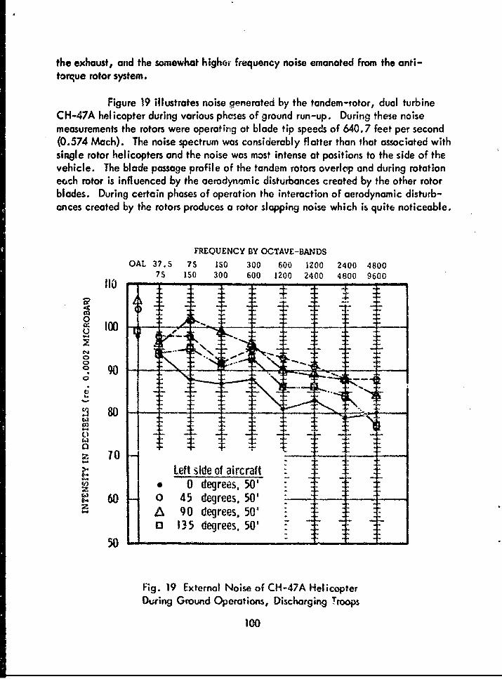
the exhaust, and the somewhat higher frequency noise emanated from the anti-torque rotor system.
Figure 19 illustrates noise generated by the tandem-rotor, dual turbineCH-47A helicopter during various phcses of ground run-up. During these noisemeasurements the rotors were operating at blade tip speeds of 640.7 feet per second(0.574 Mach). The noise spectrum was considerably flatter than that associated withsingle rotor helicopters and the noise was most intense at positions to the side of thevehicle. The blade passage profile of the tandem rotors overlip and during rotationeoch rotor is influenced by the aerodynamic disturbances created by the other rotorblades. During certain phases of operation the interaction of aerodynamic disturb-ances created by the rotors produces a rotor slapping noise which is quite noticeable.
FREQUENCY BY OCTAVE-BANDS
OAL 37.5 75 IS0 300 600 1200 2400 480075 150 300 600 1200 2400 4800 9600
110 0------
2 80
0 - _ _ _ _
S~~Left side of aircraft X_: .•z • ~~~0 degrees, 50' . .... . "
z. T
A 90 degrees. 50 .Eo 135 degrees, 501 7 :" -"•
50 .
Fig. 19 Externel Noise of CH-47A HelicopterD0ing Ground Operations, Discharging Troops
g 0-

Figure 20 shows two noise envelopes for a UH-1A helicopter during ahover at a distance of 100 feet. The upper noise envelope represents the low tohigh noise levels recorded in the frequency range from 37.5 through 600 cps andthe lower envelope represents the low to high noise levels recorded in the 600through 9,600 cps range. The most dominant noise is contained within the lowerfrequency range and becomes most pronounced at locations aft of 90 degrees. Thehigher frequency noise, although less intense, tends to follow the same generalpattern. During these measurements the main rotor blades were traveling at a tipvelocity of 710.9 feet per second (0.637 Mach).
ANGLE IN DEGREES
10 30 50 70 90 110 130 150 170
100 0 20 40 60 80 100 120 140 160 180
XO95 n,,~37 5 -" 60 . c p: "S _
"600; 7.- 9600cp ,C•/ P
§906
--
m 0 40 60 8-9600 c p s • 80
at 100' Dsac ,• 630 P, to10eresAzmthRaing
i G-R a Gear .. .S..MI- : d a e "
I- - . : ' .i,
0 20 40 60 80 100 120 140 160 180
Fig. 20 External Noise of UH-1A Helicopter at a 5' Hover, Measuredat 100' Distance, 6300 RPM, 0 to 180 Degrees Azimuth Readings
i Transmission, Gear-Reduction, and Gear-Distribution Systems.
i ~ Many present day aircraft, especially rota~ry-wing types, employ large
transmission and gear-reduction systems. These systems are used to reduce the high
101
rpm of the power plant shaft to tower rpm that 's de'ivered to propellers, rotors,and anti-torque systems. In general , the total systcm includ-_s torque distribution
shafts from the power plant, transmission and gear-redr~tion sections, and finaldistribution shafts. Of the various systems utilized, those piortaining to rotary-wingapplication are the most significant noise generators. Therefore, only rotary-wingsystems are discussed and illustrated.
The noise generated within occupied areas by these gear and shaft sys-
tems is most significant in rotary-wing aircraft where transmission units are locatedwithin or near the main fuselage. The noise spectrum generated by transmissionsystemý powered by reciprocating engines usually contains lower frequency compo-nents than those transmission systems powered by gas-turbine engines. The higherfrequency components produced by gas-turbine powered transmissions result from thehigher gear-meshing speeds of gas-turbine power plants. For instance, a gas-turbineengine may produce an engine shaft speed of 17,000 rpm, whereas a reciprocatingengine may produce on engine shaft speed of 3,000 rpm. If both of these shaft in-puts must be reduced to a rotor shaft speed of 212 rpm then it is evident that gear-transmission and shift systems mated to the gas-turbine engine wit rotate at a higherrpm than the gear-transmission and shaft systems mated to a reciprocating enginethat produces a lower rpm. Thus, the higher the rotational speeds of the gear sys-tems within the transmission, the higher w Il be the frequency components genera-ted by the meshing and impacting of the gears.
There~ are a number of types of gears used in conjunction with gear-reduc-tion, tronsmiF% . ~rind distribution systems. These. gears vary in shape, size, weight,complexity, %;A 'n the manner of application, but there ore two main types - gearsthat contact in paral lel shafts (in-line), and gears which make contact at nonparal-lel angies, usually less thaon 90 degrees. Parallel, in-line, gears are commonly usedin reciprocating engines and also for mating the power plant to other auxiliary ro-tational systems. Non~parallel gear matings ore commonly used in helicopter appli-cations where the shaft uf the main rotor is at a different angle than the center tineshaft of the power plant. A few of the major types of gears that contri*bute to thenoise generated by rotary-wing aircraft are:
make shaft velntyctpa gears which have conical pitch surfaces and are used tomak shft ontctsatangle~sess than 90 degrees, The two shafts must 6e in 6he
same plane. Bevel gears are used as shaft distribution units in many helicopterswith anti-torque rorors where the torque distribution shaft must distribute power tothe tail rotors.
Worm gears which transfer rotational motion from one shaft Lo another.Worm gears transfer shaft motion at right angles. This type of gear system offers
102

severcal advantages. The wheel gecr shaft can be rotated in either direction byche-igirg the rotational direction of the worm drive and, because the gear systemsare mated at right angles to each other, they can be located in a relatively smallspace. Worm gears are commonly used in the extention and retraction of landinggeaois and wing flaps.
Planetary and sun gears are gear systems specially located and arrang-ed to create a rotational reduction between the center shaft and the exterior shaft.A centrally located shaft, the "sun gear," is connected to the rotation of the outershaft by usually three "planetary" gears. Planetary gear systems are used in gear-reduction units for both propeller and rotor systeins, and usually consist of pinionor spur reduction gearing or both.
Impacting and meshing of gear. during rctation may stimulate naturalfrequency resonances, but friction created during gear contact is the major sourceof noise associated with gear movements. The major frequency spectrum resultingfrom gear tooth contact is dependent on the frequency of contact, the harmonicsand ncturul f-equieric chCater;stic• of the gears, the gearbox housirig, arnd thagear shafts.
Gear assemblies usually require a gearbox. The gearbox serves to sup-port entrance and exit shafts, confine and retain lubricants, and provide a shieldaguinst nois. and vibration. Gear housirrgs are importcnt sources or noise propaga-tion. The housings or gear cases are rcscran; chombers, a-nd when in contact withstructures and components of the vehicle provide a direct patkway for propagationof noise and vibration generated within the transmission housing.
The majority of helicopters utilize a power distribution system to delivertorque to main rotor(s), anti-torque rotor(s), and auxiliary components and systems.Within these systems the transmissions, gear-reduction units, couplings, bearingsand bearing supports, and drive shaft systems may gererate noise. In most instancesthesn, power drive systems contribute significantly to the internal noise environment,bvt produce little, if any, significant noise at far-field positions.
The total noise produced by power drive systems is complex and composedof a variety of noise produced by subsystems, parts, and components. The gear noisealone is quite complex and is determined or influenced by stresses plced on thegears, friction and impacting during rotation, oil and air pocketing, variations ofcasing and housing of radial noise components, and frequency and torque of gearimpacting. Usually the greater the torque the more intense will be the elementsof the noise resulting from gear friction and impacting.
103
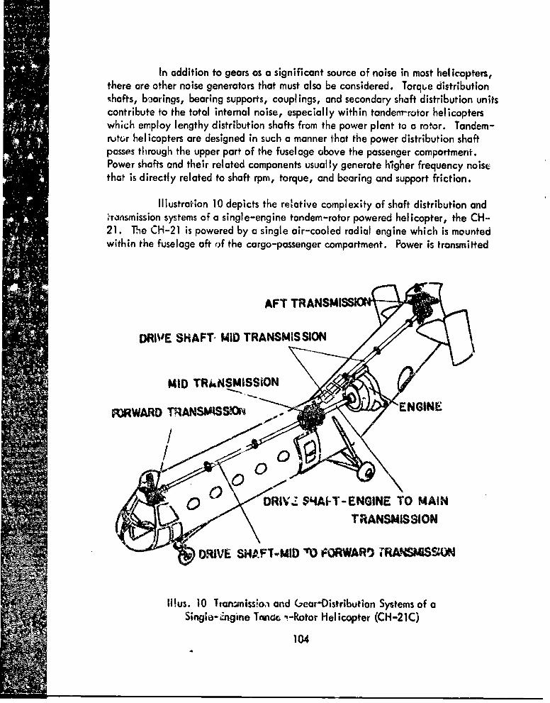
In addition to gears as a significant source of noise in most helicopters,there are other noise generators that must also be considered. Torque distribution-hafts, bearings, bearing supports, couplings, and secondary shaft distribution unitscontribute to the total internal noise, especially within tandem-rotor helicopterswhich employ lengthy distribution shafts from the power plant to a rotor. Tandem-rutor helicopters are designed in such a manner that the power distribution shaftpasses through the upper part of the fuselage above the passenger compartment.Power shafts and their related components usual ly generate higher frequency noisethat is directly related to shaft rpm, torque, and bearing and support friction.
Illustration 10 depicts the relative complexity of shaft distribution and-raonsmission systems of a single-engine tandem-rotor powered helicopter, the CH-21. The CH-21 is powered by a single air-cooled radial engine which is mountedwithin the fuselage aft of the cargo-passenger compartment. Power is transmitted
S~AFT TRANSMI•
DRIVE SHAFT- MID TRANSMISSION
MID TRUINSMISSION
MI
-0 DRIV.Z.S4AI-T- ENGINE TO MAINTR~ANSMIS SION
IWRIVE SHAF1-MID MO KORWAW• TR4"S'•ON
Itus. 10 ltanlmissloa and (,ear-Distribution Systems of a
Singia-Engine Tntv. ,-Rotor Helicopter (CH-21C)
104

from the engine to the mid-transmission and from iý, longitudinally, to the foreand ift transmissions. The mid-transmission serves only to distribute shaft powerfrom the engine, and gear reduction is achieved only at the forward and aft trans-missions. For this reason the single drive shaft between the engine and the mid-transmission, and the shafts from the mid-transmission to the forward and oft trans-missions, rotate at the same rpm as the engine, thus the mid-transmission gear sys-tem has a constant rpm equal to that of the engine. The influence o• shaft and"gear speeds is shown in Figure 21. The noise plottings shown were recorded atpositions within a CH-21C during normal cruise. The engine was operating at2,500 rpm with 37 inches of manifold pressure, and the helicopter was cruising atan indicated airspeed of 70 knots. Although the over-all noise level remained re-latively the same, the noise spectra at the three locations indicated the influenceof gear and shaft rpm on the internal noise components. Noise emanating from therotors is most pronounced at 75 to 150 cps. During these measurements the rotorswere operating at 257.7 rpm and at blade tip velocities of 576.0 feet per second
FREQUENCY BY OCTAVE-BANDS
OAL 37.5 75 IS0 300 600 1200 2400 480075 150 300 600 1200 2400 4800 9600
120 -
O 110 " - -
250000- - IP,3"M,7 nt A
100
5 90
0Left, window3 I
A Left, window 5 E-+
Fig. 21 Internal Noise of CH-21C Helicopter During Cruise,2500 RPM,, 37" MP, 70 Knots lAS

(0.516 Mach). The noise measured at the front of the cargo-passenger area (win-dow one) shows the presence of both rotor and transmission (gear reduction) noise.At positions adjacent to the mid-transmission unit the noise generated by the higherspeed transmission unit becomes evident. At window five, which is directly belowand in front of the mid-transmission, the presence of the noise generated by thehigher speed shafts and gears is further increased. The narrow-bond noise that peaksat 1,200 to 2,400 cps is primarily associated with gear me.hing and impacting of thebevel gear systems housed within the mid-transmission unit.
It has been fairly well demonstrated that increased torque applied througha gear system will result in an increase in noise. Figure 22 gives a good illustrationof how an increase in torque, while maintaining a constant rpm, will increase thenoise produced by increased meshing and impacting forces of gears within the trans-mission system of a CH-21C helicopter. The most noticeable change occurred in the
FREQUENCY BY OCTAVE-BANDS
OAL 37.5 75 ISO 300 600 1200 2400 480075 150 300 600 1200 2400 4800 9600
110 - mpmmu.
0
S"O - -- '" -:106
0
ý3 80
60
z * 2500RPM, 37St MP, 70 KIAS, 1000' Alt.
0 Hover, 2500 RPM, 40" MP,50
Fig. 22 Internal Noise of CH-21C Helicopter Measured
at Head Level Position, Center Line Cockpit
106

frequency range below 600 cps. It is interesting to note that increased torque with-out changes in rpm only caused an increase in the level of the noise but-did notcause a shift in the frequency distribution pattern of the noise.
"An illustration of the transmission and shaft distribution system of a CH-47A is shown in Illustration 11. The CH-47A is a tandem twin-turbine rotary-wingaircraft designed for heavy duty operations. The helicopter is powered by two Ly-
"- coming T-55-L-5 turboshaft engines mounted on the upper aft section of the fuse-lage. The engines simultaneously drive two tandem three-bladed rotary blades
MIAIN ROTOR SHAFTS
S SHAFT SU PPORT "
AFT4, TRANSMISSION
GAS TURBINE ENGINEAU
COMBINING TRANSMISSION
DIESHAFT
f . • "•TORQUJE SAAFT
FORWARD TRANSMISSION
Iltus. II Transmission and Gear-Distribution Systems of aTwin-Turbino.Engino Tandem-Rotor Helicopter (CH-47A)
107

through a combining transmission, drive shafting, and reduction-gear system. Theforward transmission is mounted above the aft section of the cockpit. The aft trans-
-mission, co•.irning transmission and drive shafting, is located in the aft sectionabove the main cargo and entrance door. Drive shafting from the combining trans-mission to the forward .'ansmission is housed within a tunnel on the top of the fuse-lage. The combining transmission combines the power delivered by the engines and"transmits it at reduced shaft speed to the forward and aft transmissions where addi-tional gear reduction is achieved. The various transmissions provide a total gearreduction of 66-to-1. Noise emanating from the various transmission systems isquite complex and varies from one gear-reduction unit to another. For instance,noise emanating from the forward transmission will contain relatively simple noisecomponents, whereas the total noise generated n"ar the aft transmission area willcontain a mixture of transmission type noises. NciŽ-• exposures in the aft sectionsof the helicopter will be a mixture of noise components emanating fromg the com-pressor and turbine sections of the engines, the combining transmission, and the mainaft transmission. Figure 23 demonstrates the general complexity of the noises pro-"duced within the cargo area of the CH-47A during a hover maneuver. At the for-ward position, between the first windows, noise from the forward rotor is evident inthe lower frequency range, and noise emanating from the forward transmission isevident at the 1,200 to 2,400 cps frequency range. At windows three and four thetransmission noise decreases, but noise due to overlapping of the rotors becomes"more pronounced, especially in the area at the fourth window from the front. Thenat the aft location, between the fifth windows, noise generated by the rotatingsections and components of the engines (combining transmission and aft transmission)creates a significant increase in the noise levels above 600 cps.
Rotor noise may be more intense than transmission noise because the noisegenerated by the transmission, especially the combining and gear-reduction trans-missions, is distributed within a higher frequency range and usually contains narrow-bond noise components. In teneral, if transmission systems are located above occu-pied area, the noise environment it generates within the helikopter will be consid-erably more intense than if the some unit were mounted aft or forward of occupiedareas.
Control ling the noise produced by power drive systems is not an easy taskto accomplish. The noise produced by internal components of a tran!mission sysi amare of greatest significance if the frequency of the noise approaches natural modesof resonance in the casing wall. High frequency noise can be controlled more eas-fly than IoW frequency noise. Proper acoustic treatment may help reduce the intru-sion of the higher frequencies into occupied areas of the vehicle. In may instancesacoustic treatment will not reduce th- over-all level of the noise, but will signifi-contly reduce the "loudness" of the noise. The noise generated by power drive
108

FREQUENCY BY OCTAVE-BANDSOAL 37.5 75 150 300 600 1200 2400 4800
75 150 300 600 1200 2400 4800 9600S~120 - - - . ."." .
10
S110 1
1 100
90
S--..
Z 8083.5 'o RPM, 280 psi torque
Z * CL, window I70 - 0 CL, window 3
A CL, window 4-3 CL, window 5 7 7
60
Fig. 23 Internal Noise of CH-47A, Helicopter During a Hover,Measured at Head Level in the Left Troop Seat Positions
systems can be radically altered and reduced as better engineering techniques and* materials are made available.
Summary of Noise Problems Associated with the Transmission and RelatedSystems. Transmission and related systems do not produce significant noise levelswithin the majority of fixed-wing type aircraft, but these systems and their compo-
* nents do generate rather significant noise levels within occupied areas of manyrotary-wing type aircraft. The type of noise generated by transmissions and gear-distribution systems is complex and may vary considerably from one aircraft toanother. Such factors as aging, the general condition of the individtial gears andshafts within the systems, the type and amount of fluids within the casings, the typeand condition of the vibration isolators, and many other factors have a direct bear-ing on the re~ulting noise. When determining 'he degree of noise hazard associated
109

with a given rotary-wing type vehicle, aeromedical personnel should maintain anawareness of the noise exposure related to these subsystems.
Even though acoustic differences may exist from one unit to another, onecan offer a concept of the noise generating characteristics that will remain basicallythe same from one unit to another. The main transmission gear-reduction unit is acomplex system of gears and shafts that converts the high rpm from tfe engine shkftto lower rpm for the rotor shaft. The most common gear system in the mai,.rity ciunits is the planetary type. The individual gear components are, 7n most instances,the primary determiners of the noise emanating from the total system. The "",mountof gear reduction and torque provided by a given transmission system w'll influencethe amount and type of noise generated by a system. The following listing offerssome concept for the amount of gear reduction requirements placed o., some of floetransmission gear-reduction systems in rotary-wing type aircraft (specified' in N4tio):
VEHICLE MAIN ROTOR TAIL ROTOR
OH-13 (all) 9:1 2:1OH-23B 9.17:1 1.89:1CH-21C 9.69:1 N/ACH-37B 14:1 3:1CH-47A 66:1 N/AUH-1 (all) 20.38:1 2.17:1
The amount of gear reduction required from a gear-reduction system issubstantial lygreater in aircraft powered by gas-turbine engines than those poweredby reciprocating engines. The radical gear-reduction ratio differences betweenthe two types of power plants are dictated by the main shaft rpm supplied from theengine. For instance, the Lycoming T-53-L-9 turbine engine in the UH-1B aircrafthas a shaft input to the gear-reduction transmission unit of approximately 6,397 rpm,"and requires a gear reduction of 20.38 to 1 for the main rotors and a reduction of2.17 to 1 for the anti-torque tail rotor. The Pratt and Whitney R2000 reciprocatingengine in the CH-37B has a maximum shaft input of 2,600 or 2,700 rpm, and re-quires a gear reduction of 14 to 1 for the main rotors and 3 to I for the anti-torquetail rotor systems. The requirement for higher gear-reduction capability of trans-mission systems mated to aircraft powered by turbine type engines will probablyremain the some. If anything, when newer and equally efficient rotor systems arekdeveloped, even slower rpm will be required to power the rotor systems, thus re-quiring geater gear-reducing capabilities in the gear-reduction systems.
Gears within the transmission are the major determiners of the noise era-noting from the system. Impacting ard friction of the individual "teeth," gear
110

friction, and shaft imbalances; all contribute to the total noise. Since the magni-tude and the frequency spectrum of the noise ore determined by these systems, theratio of input to output rpm determines the frequency pattern of the noise. Observ-ers near the main transmission in a reciprocating engine powered helicopter willnotice that the noise generated by the transmission is more intense in the lower fre-quency bands. Figure 24 shows noise measurements made beneath the transmissionunit of a CH-37B. The transmission unit in this aircraft has a two-stage Moanetarygear system. The noise generated by this unit is quite audible when standing be-neath the unit, especially when the observer is not wearing ear protective devices.When wearing ear protection that attenuates the extraneous noises existing withinthe vehicle, one can detect audibly the "chattering" type noise resulting from gearteeth impacting. The noises generated within areas near the transmission are in-tense enough to mask effectve speech communication. One can conduct meager
FREQUENCY BY OCTAVE-BANDS
OAL 37.5 75 150 300 600 1200 2400 480075 150 300 600 1200 2400 4800 9600
120 - -
0 110 ----------------------
2 904- . - \
o so
70
5 -00 RPM, 1-61P -M-
60
Fig. 24 Internal Noise of CH-378 Helicopter Measured+" Beneath the Transmission Unit, Station 250
* 1

speech communication by shouting in the ear of the person being spoken to, but,if proper ear protection is worn, speech communication ability can be improvedsignificantly.
During flight the internal noise near the transmission unit is less notice-able due to the intrusion of other intense noise producing mechanisms. Figure 25shows noise measurements made at six and twelve inch distances from the base ofthe transmission unit in the CH-37B. The over-all noise shows no difference, how-ever, when the microphone is placed nearer the transmission, thereby increasingthe pickup of noise emanating from this area, but there are noticeable differencesin the frequency range between 37.5 and 300 cps, and again between 1,200 and9,600 cps.
FREQUENCY BY OCTAVE-BANDSOAL 37.S 75 150 300 600 1200 2400 4800
75 150 300 600 1200 2400 4800 9600
U 10
10
9 00 - - -• - ---- -- -- --
0
S70
- * 6" beneath transmission "0 12" beneath transmission
60-
Fig. 25 Internal Noise of CH-37B Helicopter During Cruise,2600 RPM, 38" MP, 75 Knots tAS
112

The transmission system in the CH-47A (Chinook) consists of a forwardtransmission, an aft transmission, a combining transmission, two engine transmissions,and drive shafting. Power from the engine transmissions is transmitted through sep-arate drive shafts to the combining transmissions. The combining transmission com-bines the power of the engines and transmits it at reduced shaft speed through driveshafts to the forward and aft transmissions. The very high speeds of the engine arereduced to lower speeds for the rotor blades by on over-all ratio of 66 to 1.
Figure 26 shows noise measurements made at a distance of eighteen inchesbeneath the center line of the forward transmission unit and twelve inches beneaththe center line of the aft transmission. During these measurements the aircraft wasoperating at 83.5% rpm, maintaining 280 psi torque, and a 20-to 30-foot hover(measured from the tail of the vehicle) above a sbd covered area. As noted, thenoise levels are radically different between these two locations. The noise levels
FREQUENCY BY OCTAVE-BANDS
OAL 37.5 75 150 300 600 1200 2400 480075 150 300 600 1200 2400 4800 9600
120 -
.• L" • -- + . --! 10 _ __ - - - -" _ L --
o --
CM
~70U _ _
*_18" beneath fonvard unit T_0 o 12" beneath rear unit -77
Fig. 26 internal Noise of CH-47A Helicopter During a 3over,83.5% RPM, Tronsmission and Engine Noise
113

are moro intense at the aft position because of the added noise producing mechanismsof the combining transmission and the engines. The increased noise in the higher fre-quency areas, especially above 300 cps, is a mixture of noise emanating from thegear-reduction components of the combining transmission that is located in front ofthe aft transmission unit, the rotational and frictional noise emanating from the aftrotary-wing drive shaft, and from the turbine and compressor stages of the two engines.The noise produced at locations near the aft section of this aircraft can be reduced,especially within the higher frequency ranges, by properly designed, constructed,and fitted acoustic treatment material. The standard CH-47A helicopter is equippedwith acoustic blankets for both forward and aft transmission areas.
Figure 27 depicts changes in noise emitted at a position eighteen inchesdirectly below the center line of the forward transmission unit. The two noise plot-tings show the influence of acoustic blanket installation on the frequency spectrum.As noted, the over-all noise level shows negligibie change, but there are consider-able differences in the frequency spectrum. The noise in the lower frequency ranges(below 600 cps) increased with the installation of the blankets, whereas the noisein the higher frequency bands decreased. Many investigators hove reported an in-crease in the lower frequency ranges when heavy acoustic padding was used to at-tenuate noise. Even though this phenomenon occurred, decreasing the high frequen-cy noise emanating from the transmission unit caused a significant reduction in theobjectionable characteristics of the noise. The results of our investigation indicatethat the blankets should be installed whenever operationally feasible to reduce theoccurrence of exposu ' of personnel to intense narrow-band noise components.
Generally, the higher the shaft speeds of the basic power plant, themore dominant wilt be the acoustic energy produced by the internal components ofthe transmission system. Transmission systems of large reciprocating engines gener-ate gear and component noise which is distributed primarily in the lower frequencyranges. Transmission systems of small, low rpm, gas-turbine engines, like the T-53turbine engine, will generate noise which is distributed within a higher frequencyrange than that of reciprocating engine powered aircraft. Trensmission systems oflarger, higher rpm, gos-turbine engines, such as the T-55 engine, generate morehigher frequency noise than either reciprocating or small gas-turbine powered trans-mission systems. For instance, the reciprocating engine in the CH-34C is a WrightR1820 engine that con produce 2,800 rpm; the small gas turbine in the UH-IB is aLycoming T-53 engine and produces 6,607 rpm; ond the Lycoming T-55 gas-turbineengine fitted in the CH-47A generates on evefi higher rpm of 14,500.
It can be assumed thot the greater majority of gear-reduction system.fitted in most future rotary-wing aircraft powered by gas-turbine engines will gener-ate noticeable acoustic energy in a higher frequency rar-ge than presently atsociatedwith reciprocating type power plants.
114

FREQUENCY BY OCTAVE-BANDSOAL 37.5 75 150 300 600 1200 2400 4800
75 150 300 600 1ý200 2400 4800 9600120 -. - -
° ~100 " Z +-C7- 7
S+ _ __ ._ .. . . _
S90 •-- "- "" __ - _"_:-
t) 80 -- -_ __ _ --
4- 4--70 Beneath forward transmission - _-
e *•iankets removed6 Blankets in place - -
60 . .
Fig. 27 InWernal Noise of CH-47A Helicopter During.;iound Operations, 7400 RPM, 150 PSI Torque
Careful considarations must be given to transmission systems of the future,especially if they produce intense noise in the higher frequency ranges. Subjec-tively, the transmission noise of the CH-37B is more acceptable than the transmissionnoise of the CH-47A. An examination of the levels recorded in the two aircraft(reference Figure 24, page 1 11, and Figure 27, above) shows that the over-allnoise levels are almost the same, but due to the frequency distribution differences,the CH-37B is less "intense."
Ground Support Equipment.
Ground support equipment and functions are required on all fixed- androtary-wing aircraft to assure that the aircraft is maintained in a safe, reliable,and proper manner. The increasing complexity of moderm aircraft requires a per-fect balance between the rapid and effective miintainability of the aircraft and
115

the ease to which the aircraft can be returned to, and retained in, a state of opera-tional readiness. A variety of ground support equipment is used to accomplish thissuccessfully.
Not all of the various ground support units or systems generate noise, butthere ure many units which depend entirely on installed power packages in orderto achieve their given function(s). The two most commonly used power packagesthat fill this need are small reciprocating engines and small gas-turbine engines.Some of the most commonly used ground power units which use reciprocating orgas-turbine engines are:
I . Ground vehicles used to transport, transfer, load, unload, andtow. The majority of these vehicles, at the present time, are powered by recipro-cating engines or receive electrical power from storage batteries. These units donot necessarily constitute a noise hazard.
2. Electrical power may be delivered to an aircraft to energizebatteries and/or provide the necessary electrical energy to activate the starterunits, or motors, of the power plants. These units usually supply alternating cur-rent, direct current, or a combination of alternating and direct current. The major-ity of such units are powered by reciprocating engines. The units may be operatedfor rather long periods of Hume and as a result - even though the noise levels gener-ated by such units are not extremely h.gh - may pose a significant damage-risk prob-lem primarily due to the extended duration of exposures. The mass of electricallypowered equipment installed in modern aircraft not only places increasingly greaterrequirements on electrical ground support equipment, but also the units may be re-quired to operate for long periods of time - even during routine ground maintenanceand calibration.
Power plants that depend on electrical power for starting may use anelectrical ground power unit until the engine is started. Multiengine aircraft onlyrequire auxiliary electrical power until one engine has been started, at which timethe ground power unit is shut down, and the remainder of the aircraft engines arestarted from the power supplied by the operating power plant.
3. Pneumatic ground power units are usuaily required when startingreaction type engines. These units are usually powered by small gas-turbine units.The noisegenerated by these units is characteristic of small, impeller-type, gas-turbine units, containing discrete, high frequency components. During normaloperations the pneumatic power unit is started just prior to the starting of the powerplant(s). After the aircraft's engine is started, the unit is usually shut down. TheChinook and the Mohawk are using engine-mounted turbine starters. These starters
116

are roughly divided into two types. One unit is, in actuality, a small gas-turbineburning let fuel in its own combustion chamber. The other uses solid fuel in car-tridge form which is fired into a breech. However, instead of the gases slowlymoving a large piston whose linear motion is transformed by helical splines to rotarymotion, the hot gases resulting from the combustion of the cartridge propellant arenozzled against a turbine wheel and the rotating turbine shaft, through a system ofreduction gears, and drive the engine. Engines started by cartridge-start unitsreduce significantly the amount of noise exposure of maintenance and ground crewpersonnel during the starting of the power plants of reaction type engine aircraft.No longer will personnel be required to operate the pneumatic ground power units.The noise associated with the starting of the engines will actually be less, and bycutting out one of the significant noise generators during ground maintenance oper-ations, the total noise exposure of our ground maintenance personnel will be reduced.
4. Ground air conditioning equipment, including cooling, hea.ing,and/or ventilating units, may produce significant noise exposures. In most instancesthese units are powered by reciprocating engines. As these units are usually opera-ting while maintenance, repair, and other tasks are being accomplished within thevehicle, and as thky are operated for long periods of time, by themselves, or in com-bination with other ground support equipment, the noise generated near them may bequite inrense.
There are many other types of ground support equipment that producerather intense noise exposures, but the most significant, if considered on the basisof a routine, day-to-day noise exposure are those juwt mentioned. Medical person-nel, while evaluating the hazardous noise areas and jobs at a particular installation,should maintain an awareness of the large variety of ground support equipment usedby aviation personnel.
Auxiliary Power Units. Modern aircraft systems require a variety ofauxiliary systems that are used to provide electrical power, hydraulic and air power,heating and air conditioning, compressed air, etc. The majority of the auxiliarysystems are portable, but some units may be installed within the aircraft. General-ly, an auxiliary power unit provides a method of driving aircraft accessories with-out utilizing power from the main engines. Auxiliary power unifs may provide shaftpower to drive pneumatic accessory power transmission systems and pneumatic start-ers, or may be used to supply both shaft power and compressed air. These units mayalso provide electrical alternating current, direct current, or a combination of al-ternating and direct current power. Most of these units produce acoustic energiesof enough magnitude to warrant hazardous noise consideration. Units using recipro-cal engines create most of their noise in the lower frequency ranges below 600 cps,whereas those powered by gas turbines produce most of their acoustic energy in thehigher frequency ranges.
117

Each of these various types of ground support equipment possesses differentnoise characteristics, and not all produce potentially hazardous noise. Those whichuse an internal power unit usually create some degree of noise while operating. Insome cases the noise generated by individual units is of primary concern, especiallyfrom those powered by reciprocating gas-turbine engines.
Many of these units are operated for long periods of time during groundcheck-out and maintenance operations. In many instonces, maintenance personnelreceive a more hazardous noise expcsure from the ground support equipment thanfrom the noise produced by the engines oý the aircraft. Usually, the more intricateand complex the weapon system or aircraft, the greater will be the demands for useof auxiliary ground support units to operate the various systems.
Reciprocating Power Units. Figure 28 shows the noise generated at theoperator position of an MC-1 air compressor power unit. These noise measurements
FREQUENCY BY OCTAVE-BANDS
OAL 37-5 75 150 300 600 1200 2400 480075 150 300 600 1200 2400 4800 9600
0W- 100 "_ _ I0 '..
-- 0- - -o- _ _ .. - -
o -90-
Sz 70
! ZS 60 - Idle, compressor OFF
.Z4
0 High power, compressor OFFA High power, compressor ON
Fig. 28 External Noise at Operator Position of MC-1 Air Compressor Unit
118

demonstrate the influen:e that a mode of operation may have on the noise. Withthe engine at idle power and the compressor stage disengaged, the over-all noiselevel is 84 db and exhaust noise is the dominant noise generator. The noise fromthe exhaust is distributed primarily in the low frequencies (37.5 through 150 cps).As power is increased, the magnitude of the exhaust noise also increases, causingan increase of twelve db in the over-all noise. The higher rpm also creates moreintense harmonics within the spectrum of the exhaust noise, but the first c.<tave"band still contains the most intense noise. When the air compressor stage is engaged,the over-all noise increases to 103 db, and the spectrum demonstrates an increase inthe 150 through 600 cps frequency range due to compressor component noise. Withthe compressor engaged, exhaust noise is still most pronounced in the very low fre-quency ranges.
Most auxiliary electrical power units are powered by reciprocating engines,and the exhaust port is usually located at the opposite end from the operator's panel.Figure 29 shows noise plottings at three positions near an MD-3 electrical power unit.
FREQUENCY BY OCTAVE-BANDS
OAL 37.5 75 IS0 300 600 1200 2400 480075 150 300 600 1200 2400 4800 9600
120 -. - - -00
CIoU790'
70 Operator position
,.z 0 Exhaust port side "T :.. • - _A Front side, opposite exhaust- .'
S60
SFig. 29 External Noise of -D-3 C;round Power Unit
119
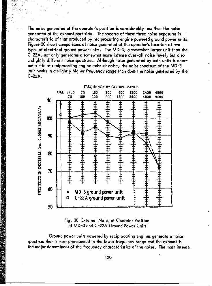
The noise generated at the operator's position is considerably less than the noisegenerated at the exhaust port side. The spectra of these three noise exposures ischaracteristic of that produced by reciprocating engine powered ground power units.Figure 30 shows comparisons of noise generated at the operator's location of twotypes of electrical ground power units. The MD-3, a somewhat larger unit than theC-22A, not only generates a somewhat more intense over-all noise level, but alsoQ slightly different noise spectrum. Although noise generated by both units is char-acteristic of reciprocating engine exhaust noise, the noise spectrum of the MD-3unit peaks in a slightly higher frequency range than does the noise generated by theC-22A.
FREQUENCY BY OCTAVE-BANDS
OAL 37.5 75 150 300 600 1200 2400 480075 150 300 600 1200 2400 4800 9600
10
0
04
902 80
70)
zI • 60
* MD-3 ground power unit0 C-22A ground power unit -
Fig. 30 External Noise at Cperator Positionof MD-3 and C-22A Ground Power Units
Ground power units powered by reciprocating engines generate a noisespectrum that is most pronounced in the lower frequency range and the exhaust isthe major determinant of the frequency characteristics of the noise. The most intense
120

noise is usually found at locations near the exhaust port. Also, as engine loadingincreases, the noise level tends to increase due to increased torque required fromthe engine. Even though the exhaust (where the noise is usually found to be mostintense) is located at a position opposite the control panel, it should be rememberedthat, when the unit is parked next to an aircraft or engine, the operator's panel *-!usually placed so that a full view of the aircraft or engine is afforded the GPU op-erator. For this reason, noise generated by the exhaust is p.opagated at locat'onsbetween the GPU and the aircraft - thus persorn-el working on the aircraft may re-ceive a significant amount of exhaust noise.
For the most part, ground power units are fitted with quite effective muf-flers, but since the major noise component ;s generated within the lower frequencies,the amount of noise attenuation is limited.
Gas-Turbine Power Units. The requirements and utilization of groundand airborne auxiliary gas-turbine units have increased steadily. Gas-turbine aux-iliary ground power units, such as the MA-i and MA-1A units, are used to providepneumatic power for starting many gas-turbine type power plants. The MA-1A is thenewer version of the MA-1. The MA-1A is utilized primarily for the purpose of pro-viding pneumatic power for starting gas-turbine type power plants, whereas the olderMA-i unit is utilized to provide forced air ventilation and circulation within theinteriors of aircraft. The noise levels generated by the MA-1A unit demonstrate thesignificant degree of noise reduction which can be achieved by proper design, en-gineering, and noise control considerations. The MA-i and especially the MA-1Aunits are routinely used by ground crew personnel for engine starting.
Utilization of gas-turbine units and gas-turbine compressors will probablyincrease and broaden in scope of application, especially for aircraft powered byreaction type power plants.
Figure 31 shows a comparison of noise measurements made at the operatorpositions of the MA-I and MA-IA pneumatic power units. The MA-1A is trailermounted and is a gas-turbine, air driven generator of 191 horsepower. The unit de-livers 2.2 pounds of air pressure per second at an air pressure of 52.5 psi. This typeof unit is required whenever a gas-turbine engine of an aircraft is started. As moreand more turbine powered aircraft are developed and added to the inventory formilitary operations, the need and utilization of such ground power units will in-
- crease. Needless to say, the noise exposures generated by these units are uxtremelyintense, and a factor to consider is that personnel ore required to work around suchunits for rather extended periods of time. The d&gree of significance imposed bysuch work schedules is dependent on the duration of exposure incurred by groundmaintenance personnel.
121

-. *,.S
FREQUENCY BY OCTAVE-BAN~DSOAL 37.5 75 150 300 600 1200 2400 4800
75 150 300 600 1200 2400 4800 9600130
o 120 . F .
UM
10
100
: 80
ze MA-I (old unit)o0 MA-IA (new unit)
70 --. •'
Fig. 31 External Noise at Operator Positionof MA-i and MA-iA Ground Power Units
Figure 32 shows the general noise exposure generated by the electricalauxiliary power unit fited in the CH-37B. As noted, the most intense noise isdistributed within the lower frequency ranges, and is due to the reciprocating en-gine used to power the electrical generating mechanisms of the unit. This auxiliaryunit is turned off after the engines of the arcraft have started as there is no require-ment for operating the unit during normal flight since electrical power is providedby the generators of the main engines.
Aerodynamic and Boundary Layer Disturbances.
Aerodynamic noise generated by disturbances in the boundary layer sur-rounding a moving body is common to almost all aircraft, and when associated withhigh speed aircraft may result in quite significant noise problems. The degree ofsignificance is directly related to the speed of the vehicle and the relative locationor position of the occupant within the aircraft.
122

FREQUENCY BY OCTAVE-BANDS
OAL 37.5 75 150 300 600 1200 2400 480075 150 300 600 1200 2400 4800 9600
110
g 90
S80S:-90- - - .
S701 0
50
Fig. 32 Internal Noise of: CH-37B APU Measured at Station 402
Noise due to aerodynamic disturbances has assumed a role of major sig-nificance due to the increased airspeeds now obtainable by the majority of militaryaircraft. As airspeed increases, especially at lower altitudes, noise due to aero-dynamic disturbances assumes greater importance. At higher altitudes, aerodynamicnoise is less significant than during operation at lower altitude at the some speed.
Boundary layer noise is a phenomenon associated with high speed passageof a moving body through an atmosphere. Boundary layer disturbances ore generatedby a thin layer of air next to the skin of the fuselage. The greater the speed, themore significant the boundary layer influences on noise and vibration generated in-ternally. Boundary layer disturbances not only generate noise problems, but mayalso produce sonic fatigue. These intense disturbances may interfere with speechreception and/or discrimination, interpretation of information instrument readings,operation of guidance controls, end auxil iary power systems.
123

Boundary layer disturbances are associated with high speed aircraft andare gaining significance due to increased performance characteristics of neweraircraft. Noise due to aerodynamic disturbances is of primary concern because itincreases the intensity of the middle and higher frequencies which results in agreater degree of speech masking. At present boundary layer noise is not a seriousproblem, but as Army aircraft attain faster speeds the importance of this type ofnoise can be expected to increase.
Air and Dive Brake Systems. Aviators of high performance aircraft canincrease maneuverability and reduce landing speeds by extending a speed (or air)brake panel into the airstream. Speed brakes are usually hinged and, when extendedoutward and forward into the airstream, increase drag. Since ,these systems are usu-ally controlled hydraulically, the degree of extension can be controlled throughoutits entire range. The majority of systems are extended into the airstream at positionsvariable from full open through full closed operations. By extending the air brakeinto the slipstream, the turbulence and air passage friction increases the noise andvibration which, in turn, are transmitted through the surrounding support and ex-tension system. The nearer the air brake to occupied areas, the more noticeablewill be the noise and vibration generated by the system during deployment.
Airspeed and altitude have a dominant influence on the degree of noisegenerated during the deployment of an air brake. Generally, the higher the air-speed, and the lower the altitude, the more intense will be the air brake noise.Air brakes of some aircraft may produce more noise as airspeed is decreased becauseat very high speeds the brake would not open fully, but as the speed decreases thebrake slowly extends further into the slipstream, thus producing more noise withdecreasing airspeed.
Landing Gear Noise. The extension of an aircraft's landing gears intothe slipstream may produce an increase in internal noise similar to that produced bythe extension of on air brake system. Generally, the extensicn of a landing gearsystem produces only a slight increase in internal noise because most landing gearsystems are housed within wing wells. However, if an aircraft has part, or all, ofthe landing gear housed within the main fuselage, noticeable noise may result whenthe landing gear is extended. Main landing gears mounted in pods and attached tothe sides of the main fuselage do not usually generate much noise once the wheelsare extended. The actual noise level increases only slightly during operation of thewheel well doors, but since the doors operate with rapid movements, there may bea "thudding" or "slamming' as the doors open and close (especially during closing).When extended into the airstream, the basic noise resulting from air friction will below frequency in character. Higher frequency elements of the noise are attenuatedby the structural damping.
124
Ventilating and Air Conditioning Systems.
Fans, blowers, re-cycling airflow units, as well as the air distributionducts and vdnt systems, create various types and degrees of noise. These variousnoise sources are as follows:
Fans which move masses of air are usually of two basic types - axialor centrifugal ."xial fans are commonly referred to as propeller-type fans. Cen-trifugal-type fans move the air outward from the central axis of rotation, and arethe more commonly used type aboard aircraft, especially in providing air circula-tion and cooling for electronic equipment.
Airflow noise is created by air friction and resonance as air flowsthrough and out of circulation, ventilation, and other airflow retainers. Ventila-tion airflow noise is usually created by the use of fans and/or ram air within theaircraft. Noise is generated either by the motor and blades of the circulating fanor by aerodynamic friction produced as the cir mass is propelled through exits ofthe air ducts.
125
Chapter 6
FUTURE NOISE AND VIBRATION PROBLEMS IN ARMY AVIATION
Army Aircraft Armment Systems.
The development program for armed helicopters began in 1956 when theCommanding General of the U. S. Continental Army Command became concernedover the likelihood of having to fight brush-fire wars. These wars would requireforces which could be deployed quickly to a troubled area and be tailored to fita particular task. As a result of a directive to major headquarters to consider thecreation of mobile task forces to perform the function, the U. S. Army AviationSchool activated a unit called the Sky Cavalry Platoon in March, 1957. This wasa reconnaissance-type force completely mounted in armed helicopters. Based uponthe experiments and experiences of this unit, later redesignated the 8305th AerialCombat Reconnaissance Company, and subsequent troop tests, the concept of Armyhelicopters with automatic weapons, rockets, and guided missiles has been acceptedand, therefore, standard weapon systems are being adopted.
Arming Army aircraft greatly enhances the capability of these aircraftto accomplish their assigned missions as these armed aircraft are immediately avail-able and responsive to ground commanders. They perform the most recent functionsof Army aviation - aerial fire support. Aircraft within the field Army, which areto be used primarily in a fire support role, will have an integrated or built-in wea-pon system which will be d more or less perman-nt installation. These would not bedetachable except for the end item, the weapon itself. The use of common mount-ing methods allows for maximum flexibility in the selection of weapons systems tobe utilized on a particular mission. Eventually an integrated weapons system willbe developed that will include all of the fire control equipment as on integral portof the aircraft system.
The number of armament systems scheduled for test and evaluation by Armyaviation units is quite extensive (see Appendix 2). At present the missile and rocketsystems do not constitute serious noise problems. However, preliminary measurementsof the XM-1, XM-2, and M-60E3 wchine gun systems indicate that a potentiallyhazardous situation exists with automatic weapons. The peak sound pressure levelsvary considerably. This variation is primarily due to 1) type of system, 2) type ofgun mountings, 3) location of the muzzle in relation to occupants of the aircraft,
126
and 4) whether the cockpit and cargo windows and/or doors are open or closed. Fir-ing maneuvers, i.e., ground fire (bore sighting), hovering, and various cruise air-speeds are not significant variables.
An investigation of the hazardous noise associated with the helicopterarmament program will be conducted at Fort Rucker during the next few months.
"* STOL and VTOL Aircraft.
"Short take-off and landing (STOL) refer. to aircraft capable of taking off"from and landing on short unimproved landing areas. VTOL or vertical take-off andlanding includes all nonrotor aircraft capable of taking off and landing within 50feet of a 50-foot obstacle.
Putman 30 , in a report on environmental and engineering characteristicsof unconventional, high performance, VTOL aircraft, emphasized that during thedevelopmental stages special attention should be given to the unique types of noiseand vibration that might be generated by these vehicles.
Many different configurations and operating principles of vertical andshort take-off and laiiding aircraft have been proposed (see Appendix 3). A fewaircraft have been sufficiently developed and operated to allow fairly extensivenoise and vibration studies. These investigations have been conducted on a smallscale, but there is some evidence that the major;ty of high performance STOL andVTOL aircraft present distinct noise problems, primarily those amociated with thepower plant and/or type of propulsion system used. The problem is further compli-cated by such variables as blade loading, jet exhaust velocity, and propeller tipMach number. Each of these factors will hove a direct influence on the amount andtype of noise produced.
Generally, it can be expected that as more powerful and efficient powerplants become operational, the feasibility of high performance STOL and VTOL air-croft will increase. For example, gas-turbine engines have expanded into a varietyof modified versions. Some of the newer power plants are turbofan, bypass, anddirect-thrust lift types. The outstanding improvements recently made in the develop-ment of small gas-turbine engines have offered a wide range of turboshaft enginesfor rotary-wing applications. The majority of these units offer medium shaft powers,
Sgood economy, and in many instances, reduced noise. At present, exhaust noiseemanoating from reciprocating engines in conventional hel icoptets remains one of themost domnant noise sources. However, it is belleved that in properly designed tur-bine powered helicopters, engine noise can be reduced to the point where it can beasupted that the main source of noise is due to the shedding of vortices from the
127

main rotor. Investigations of noise generated by various blade loadings and rotortip speeds have shown that the noise level decreases with decreasing tip speed andblade loadings. Measurements have indicated that helicopter rotor noise fluctuatesin amplitude at a rate corresponding to the blade passage frequency.
Present data indicate that VTOL aircraft powered by pure turbojet enginesproduce excessive noise levels for city operation. The most significant noise pro-duced is due to the mixing of the jet exhaust with ambient air. The majority ofSTOL and VTOL aircraft utilizing jet type engines will require a wide range ofthrust, but these aircraft will probably not need augmented thrusts, such as after-bu-ning. The velocity of the jet stream has a direct influence on the amount ofnoise produced and accounts for a wide range of noise levels.
The present trend is toward the utilization of turbofan and bypass enginesas basic power plants for VTOL airc.aFt. The turbofan engine offers some potentialfor noise reduction due to its inherently low jet exhaust velocity. However, sub-stantial levels in the higher frequency bonds may be present due to the combinedeffects of fan noise and incomplete mixing of primary and secondary air. As researchand development continue in the application of turbofan engines, it is expectedthat the noise chkracteristics of these engines will improve and the final productionof highly developed turbofan engines will demonstrate significantly less noise thanpresent day turbojet engines. The bypass engine, on the other hand, has similarnoise prcblems to the jet type engine since the primary airflow posses through thecombustion section producing tremendous exhaust velocity.
Turboprop aircraft produce very intense noise levels. However, thispropeller noise may be reduced by either reducing the propeller tip Mach numberor by increasing the number of blades, or both. The majority of high performanceturboprop powered vehicles incorporate three- or four-blade propeller systems. In-creasing the number of blades beyond four will probably not result in significantnoise reductions and would increase the complexity of the propell-er system. Themost practical application for noise reduction in propeller systems is usually achievedby reducing the propeller tip Mach number.
A large amount of work is being expended on the reduction of noise inand around conventional aircraft, and this effort may produce breakthroughs thatwill be applicable to STOL and VTOL aircraft. However, it must be rememberedthat the VIOL aircraft need three to four times the installed thrust of conventionalaircraft and therefore tKe noise problem is more acute from the onset.
128

Vibrations Associated with Army Aircraft.
During the past few years considerable research has been conducted onthe causes, effects, and control of vibration. A major part of this research hasbeen applied specifically to modes and phases of vibration expected, or presentlyexisting, in fixed- and rotary-wing aircraft. The results indicate that man and/ormachine can be exposed to definite restricting modes of vibration energies beforecartain undesirable effects occur.
Although the majority of research in this field has been directed towardundesirable effects or influences, there may be certain factors and types of vibra-tional modes that are somewhat desirable. For instance, Randle 31 studied the in-fluence of vibration on helicopter pilots and found that they utilize the vibrationwhich they perceive as a sensory evaluation tool. Seemingly, the modes of vibra-tions perceived assisted the pilot in evaluating normal flight features during controlof the aircraft, and also assisted in the detection and diagnosis of possible systemmalfunctions. Randle further emphasized the possible utilization of simulated vi-brational modes as a practicc! training device in the initial phases of helicopterpilot training.
Vibrations of primary concern are related to mechanical, acoustical, oraeroelastic disturbances. Listed below are some of the more significant operationalareas or circumstances where undesirable vibration may be present.
1. Maintenance test areas:
a. Reciprocating engines;b. Gas-turbine engines, jet type;c. Propeller, rotor, and engine run-up; including reciprocating,
turboshaft, and turboprop power plants.
2. Ground power equipment:
a. Pneumatic hand tools;b. Large diesel engine powered generators.
3. Aircraft during ground run-up opercaions:
a. Reciprocating engines in rotary- and fixed-wing aircraft;b. Acoustically induced vibration of jet exhaust of reaction type
engines during high power operation;c. Propellers and rotors.
129

4. Aircraft while airborne:
a. Structurally propagated vibrations due to excitations createdby 1) power plant disturbances; 2) engine exhaust vibrations; and 3) engine shaftfeedback from propellers and rotors.
b. Acoustic and aeroelastic vibrations induced by 1) engine ex-haust of reciprocating or gas-turbine engines; 2) pressure disturbances generated byrotor or propeller blades; 3) structural response due to increased airspeed and dy-namic loadings; and 4) other responses, such as vibrations induced due to aerody-namically stimulated wing and surf-ace flutter (related to high speed).
Various methods are available to help reduce undesirable vibrations. Oneof the most common avenues of propagation is by structural vibration. The powerplant may produce considerable vibration and the degree to which these energies aretransmitted through the aircraft are often dependent on the type and condition of de-vices used to control the vibrations. Methods of vibration reduction ate detailedbelow.
1. Vibration isolation and anti-vibration systems. Power plant mount-ings are usually designed to minimize the transmission of vibrations into the structureof the aircraft and prevent resonant vibrations of the aircraft structure by vibratoryforcing functions generated by the operation of the power plant.
2, Power plant-propeller system vibrations. Vibrations generated bypower plants and propellers, when propagated directly through the structure of thevehicle, may produce excessively high levils of vibration. These vibrations, ifpresent, result from inherently imbalanced forces and couples of the engine, una-voidable imbalances in the propeller, and occurfences of small errors in blade pitchand the rotational profile of the propeller. These undesirable forces are usually con-trolled by the use of isolation mounting systems. These systems are essentially flex-ible supports which allow vibrating forces acting on the power plant to be neutral-ized by small, nonresonant oscillations of the power plant mass itself, thus isolatingthe vibratory dis'jrbances from entering the aircraft directly. This type of engine-to-frame mounting is used primarily when the vibrations generated by the engine,components, and/or propellers are within a frequency range that approximatesresonant frequencies of the structures and components of the aircraft to which theyare mated.
3. .Absorpton mountih,.g systems absorb the energy of power plantvibrations and dissipate it as heat within the absorbing material of the mounting.They are commonly used on aircraft whose power plant components are attached tothe aircraft structure and generate vibrations at frequencies much higher than the
130

natural modes of vibration of the aircraft structure. Absorption type mounting sys-tems are commonly used to reduce the transmission of vibration to the aircraft struc-ture on vehicles containing a) turbojet and turbofan engines that depend on exhaustthrust for propulsion of the aircraft; b) independently mounted auxiliary stage super-chargers; c) independently mounted gear-reduction units not driving propellers; and/or d) ramjet and rocket power plants.
4. Isolation mounting systems are usually provided when the follow-ing are used: a) reciprocating engine and propeller combinations, including bothradial and in-line engines; b) reciprocating engine in a submerged installation whichdrives propellers through an extension propeller shaft; c) independently mounted pro-pel I er assemblies; d) independently mounted gearbox-propeller combinations; 3)aeropulse or intermittent type jet engines; or f) turboprop engines.
Summary. Discomfort of airccew personnel may result from excessivevibration and can, in many instances, interfere with the successful accomplishmentof an assigned mission. Flutter and other aeroelastic disturbances, associated withmore sophisticated Army aircraft, may generate disturbances sufficiently violent tocause almost instantaneous failure of the structure affected. Free and forced vibra-tions may cause excessive structural stresses within the aircraft which lead to fatiguefailures. Excessive vibrations of installed components may result in malfunction orfailure of such components. Needless to say, vibration energies of these magni-tudes usually produce physiological and psychological disfurbances. Aviation med-ical research has demonstrated that the human system cannot tolerate as high a levelof vibration as permitted by the allowable stresses in the aircraft structure.
It is obvious that certain vibration limitations must be emphasized, es-pecially where man is concerned. Emphasis is being placed on eliminating exces-sive, or undesirable, vibration associated with aircraft operations. Inherent withinthis program is reducing 1) human physical fatigue and discomfort, 2) hearing dis-turbances among aircrew personnel, 3) undesirable effects of vibration on equipmentand aircraft structures, and 4) improving audible communication. If these areas areconsidered during the early phases of aircraft design and development, the undesir-able aspects of vibration on future Army aircraft can be minimized.
131

APPENDIX 1
PROCUREMENT INFORMATION ON STANDARD ARMY EAR PROTECTORS
The following standard Army items are included in TA 21 (Peace):
(a) Helmet, Flying, Protective APH-5
Federal Stock Number Size Approximate Cost
8415-577-4142 Medium $93.908415-577-4143 Large
(b,) Aural Protector, Ear, Sound
Federal Stock Number Approximate Cost
4240-361-3612 $12.00
(c) The Standard Army V-51R Ear Plugs and carrying case are in-cluded in the Medical Stock List as follows:
Stock Number Description Unit
6515-299-8287 Case, Ear Plugs each6515-664-7858 Plug, Ear, Noise Protection,
Extra Small pkg. 24s6515-299-8290 Plug, Ear, Noise Protection, Small pkg. 24s6515-299-8289 Plug, Ear, Noise Protection, Medium pkg. 24s6515-299-8289 Plug, Ear, Noise Protection, Large pkg. 24s
6515-664-7859 Plug, Ear, Noise Protection,Extra Large pkg. 24s
If plugs are not available, they may be ordered through Medical Supply.
132

APPENDIX 2
PROPOSED ARMY AIRCRAFT WEAPONS SYSTEMS
DESIGNATION DESCRIPTIONOld New
XM-1 XM-1 Armament Subsystem, Helicopter, .30 Caliber,Machine Gun, Twin Gun.
XM-1 XM-1E1 Armament Subsystem, Helicopter, .30 Caliber,Machine Gun, Twin Gun.
XM-2 XM-2 Armament Subsystem, Helicopter, 7.62 mm, .30Caliber, Machine Gun, Twin Gun.
XM-3 Armament Subsystem, UH-1B, 2.75 inch AreaRocket Weapons System (ARWS), 24 Rockets oneach side.
XM-4 Armament Subsystem, CH-34, 2.75 inch InterimArea Rocket Weapon System (IARWS), 24 Rocketson each side.
XM-138/75 XM-!i Armament Subsystem, Helicopter, 40 mm GrenadeLauncher.
XM-153/154 XM-6 Armament Subsystem, CH-21, 7.62 mm MachineGun, Quad Gun.
XM- 153/155 XM-6E1 Armament Subsystem, CH-34, 7.62 mm MachineGun, Quad Gun.
XM-6E3 M-6 Armament Subsystem, UH-1 B, 7.62 mm MachineGun, Quad Gun.
XM-7 Armament Subsystem, M-60C, Machine Gunsmounted on LOH.
133

DESIGNATION DESCRI PTIONOld New
XM-8 Armament Subsystem, 40 mm, Grenade Launchermounted on LOH.
XM-9
XM-10 Armament Subsystem, Follow-on 7.62 mm XM-2Subsystem, mounted on OH-i13 and OH-23 Hel icopters.
XM-1 1 ATGM SS-11 mounted on UH-1 B.
XM-12 Armament Pod, Aircraft, 20 mm Automatic Gun.(This is c podded configuration of gun, 20 mm auto-matic: M-61. 1250 rounds of ammo will be self-contained in the pod).
XM-13 Armament Pod, Aircraft, 40 mm Grenade Launcher.(This is a podded version of the XM-75).
XM-14 Armament Pod, Aircraft, Caliber .50 Machine Gun.(This is an "off-the-shelf" procured gun pod utilizingthe M-2 gun for fixed-wing use).
XM-15 Armament Subsystem, Helicopter, 7.62 mm MachineGun, Twin High Rote Gun. (This unit is a system toreplace the M-6).
XM-129 Launcher, Grenade. (This is a redesigned version ofthe XM-75 to reposition the drive drum).
XM-133 Machine Gun, 7.62 mm, Gas Drive. (This is thehigh cyclic rate gun with gas drive).
XM-134 Machine Gun, 7.62 mm, Electric Drive. (This is thehigh cyclic rate gun with electric drive).
134

APPENDIX 3
PROPOSED STOL AND VTOL AIRCRAFT
1. Rotor Aircraft other than Conventional Helicopters;
Piasecki 16 H Pathfinder (reciprocating, rotor + 5hrouded prop).
2. Gyrodyne: (jet assisted rotors)
a. McDonnell XV-1 (gas turbine).
b. Fairey Rotodyne (gas turbine).
3. Propeller Aircraft:
a. Deflected Slip Stream.
(1) Ryan VZ-3RY Vertiplane (gas turbine).
(2) Fairchild (reciprocating).
b. Tilt Wing.
(1) Kaman K-16B.
(2) Hiller X-18 (gas tubine).
(3) Vertol V7-2 (.3As turbine).
(4) Ryan XV-SA (reciprocating) (Amy).
c. Tilt Propeller.
(1) Curtiss-Wrlght X-19 (AF/A.rmy/Navy).
(2P Bell XV-3 Convertiplane &reciprocoting) (Army).
135

4. Shrouded Propeller Aircraft!
a. Doak VZ-4DA.
b. Piasecki 16 H Pathfinder (reciprocating. rotor + shrouded prop).
5. Fan Lift Aircraft:
a. Piasecki Airgeep - Seageep I (reciprocating).
b. Piasecki Airgeep II (reciprocating).
c. Vanguard Air and Marine Corps Vanguard 30.
d. Vanguard 2D Omniplane.
e. General Electric - Ryan XV-5A (Army).
6. Jet Aircraft:
a. Lockheed XV-4A Hummingbird (Army).
b. Ryan Vertijet X-13 Pogo.
c. Bell X-14A.
d. Hawker Siddeley XV-6A (AF/Army/Navy).
7. Tri-Service (turboprop) (AF/Army/Navy):
a. Chance Vought, Ryan, and Hiller XC-142A (VHR 447).
b. Bell X-22A.
136
BIBLIOGRAPHY
1. Ad Hoc Committee on Requirements for Training in Support of the Army AviationProgram, 1960-1970. Hqs USCONARC, Fort Monroe, Va., 22 Dec. 1960.
2. Air Force Regulation 160-3. "Hazardous Noise Exposure," 29 Oct. 1956.
3. Benox Report. "An Exploratory Study of the Biological Effects of Noise." Uni-versity of Chicago, ONR Project Nr 144079, 1 Dec. 1953.
4. Beranek, L. L. "Noise control in office and factory spaces." Trans. Ind. Hyg.Foundation, Bull. 18:26-33, 1950.
5. Beranek, L. L., ed. Noise Reduction. New York, McGraw-Hill, 1960.
6. Berry, C. A. and H. K. Eastwood. "Helicopter Problems: Noise, CockpitContamination and Disorientation." Aerospace Medicine, 31: 179-190, 1960.
7. Brooks, G. W. and H. W. Leonard. An Analysis of the Flopwise Bending Fre-quencies and Mode Shapes of Rotor Blades Having Two Flapping Hinges toReduce Vibration Levels. NASA, Technical Note D-633, Dec. 1960.
8. Carterette, E. C. and M. Cole. Comparison of the Receiver Operating Char-acteristics for Visual and Auditory Reception of Messages. California Univer-sity Technical Report No. 2, 18 June 1959.
9. Cox, C. R. and R. R. Lynn. A Study of the Origin and Means of ReducingHelicopter Noise. U. S. Army Transportation Research Command, Ft. Eustis,Va. TCREC Technical Report 62-73, Nov. 1962.
10. FM 61-100, "The Division." Headquarters, Department of the Army, Jan. 1962.
S11. Green, D. M. Detection of Complex Auditory Signals in Noise and the Critical* Band Concept. Air Force Communications Research Center, Cambridge, Mass.
Technical Report 82; 2659-4-T, April 1958.
12. Harmon, F. L. and B. T. King. Vulnerability of Human Performance in Corn-municotions. Bureau of Naval Personnel. Technical Bulletin 61-1, Jan. 1961.
137

13. Harris, C. M., ed. Handbook of Noise Control. New York, McGraw-Hill,1957.
14. Harris, J. "An Evaluation of Ear Defender Devices." U. S. Naval MedicalResearch Laboratory, New London, Conn., Vol. 14, No. 11, 15 Dec. 1955.
15. Hirsch, I. J. "The Influence of Interaural Phase on Interoural Summation andInhibition." J. Acoust. Soc. Amer., 20: 536-544, 1948.
16. Holland, J. G. and W. A. Lee. The Influence of Message Distortion andMessage Familiarity. Wright-Patterson Air Force Base, Ohio. WADC Tech-nical Report 54-287, April 1955.
17. Hubbard, H. H. and D. J. Maglieri. "Noise Characteristics of HelicopterRotors at Tip Speeds Up to 900 Feet Per Second." J. Acoust. Soc. Amer.,32: 1105-1107, 1960.
18. Kryter, K. D. "The effects of noise on man." J. Speech and Hearing Disorders,Mono., Suppl., I Sept. 1950.
19. Licklider, J. C. R. Studies in Aural Presentation of Information. Air ForceCommunications Research Center, Cambridge, Mass. Technical Report No.58-53, Oct. 1957.
20. McNamara, R. S. Statements Before the House Armed Services Committee on30 January-I February 1963. Reprinted in Army, 13: 20, 1963.
21. McNamara, R. S. Statement Before the House Armed Services Committee,"The Fiscal Year 1964-68 Defense Program and 1964 Defense Budget." Con-gres3ional Record, 30 Jan. 1963.
22. Means, C. P. "Army Mobilizes to Improve Mobility," Armed Forces Magazine,8. 12-13, 1962.
23. Metcalf, C. W. and R. G. Witner. "Noise Problems in Military Helicopters,"J. Aviation Medicine, 29: 59, 1958.
?4. Military Specification. "Acoustical Noise Level in Aircraft, General Specifi-cation for," MIL-A-8806(ASG), Department of Defense, 25 Oct. 1956.
5. Miller, G. A. "The Maskingof Speech." Psychol. Bull., 44: 105-129., 1947.
138

26. Miller, L. N. and L. L. Beranek. "Acoustical Design for Transport Helicopters,"Noise Control, 5: 6, 1959.
27. Nixon, C. W., and Others. Performance of Several Ear Protectors. Wright-Patterson AFB, Ohio. WADC Technical Report 58-280, May 1959.
28. Noise Control, Journal published by the Acoustical Society of America, 335
East 45th Street, New York, 1955-1961.
29. Powell, H. B. "Army Airmobility." U. S. Army Aviation Digest, 9: 3-5, 1963.
30. Putnam, V. K. Some Human Engineering Aspects of Several UnconventionalAircraft. AGARD Report No. 244, May 1959.
31. Randle, R. J. Vibrations in Helicopters; Training Considerations. Wright-Pat-terson AFB, Ohio. WADC Technical Note 59-61, March 1959.
32. Rosenblith, W. A., and Others. Handbook of Acoustical Noise Control, Vol.II, Noise and Mon. Wright-Patterson AFB, Ohio. WADC Technical Report52-204. June 1953.
33. Sataloff, J. Industrial Deafness. New York, McGraw-Hill, 1957.
34. Sternfeld, H., Jr., and Others. Study to Establih Realistic Acoustic DesignCriteria for Future Army Aircraft. U. S. Army Transportation Research Corn-
.mand, Ft. Eustis, Va. TREC Technical Report 61-72, June 1961.
35. Stevens, S. S., and Others. "The Masking of Speech by Sine Waves, SquareWaves and Regular and Modulated Pulses." J. Acoust. Soc. Amer., 18:418-424, 1946.
36. TB MED 251, "Noise and Conservation of Hearing," Deportment of the ArmyTechnical Bulletin, 11 May 1956.
37. Vance, C. R. "The Army in Review." Extracted from Secretary Vance's state-ments before the House and Senate Committees on Armed Services, February1963. Atmy Information Dig., 18: 2-7, 1963.
38. Webster, J. C. and E. R. Rubin. "Noise Attenuation of Ear-Protective Devices."Sound, 1: No. 5, Sept.-Oct. 1962.
19•

DISTRIBUTION LIST OF USAARU REPORTS
Project No. 3AO1250-1A-806-A Behavioral Sciences Division
No. ofCopies
DEPARTMENT OF DEFENSE20 Defense Documentation Center for Scientific and Technical Information,
Cameron Station, Alexandria, Virginia 22314.
U. S. ARMY1 US AMEDS Combat Development Group, Brooke Army Medical Center,
Fort Sam Houston, Texas.1 Walter Reed Army Institute of Research, Walter Reed Army Medical Center,
Washington 12, D. C.1 M,-dical Equipment Development Laboratory, Fort Totten, Flushing 59,
L. I., 4ew York.I US Army Prosthetics Research Laboratory, Walter Reed Army Medical
Center, Washington 12, D. C.I US Army Medical Research Unit, Kuala Lumpur, Malaya.1 US Army Medical Unit, Fort Detrick, Maryland.1 US Army Tropical Research Medical Laboratory, APO 851, New York, N. Y.1 US Army Medical Research Laboratory, Fort Knox, Kentucky.1 US Army Surgical Research Unit, Brooke Army Medical Center, Fort Sam
Houston, Texas.1 US Army Medical Research & Nutrition Laboratory, Fitzsimons General Hos-
pital, Denver 30, Colorado.I US Army Medical Research Unit, Europe, APO 180, New York, N. Y.I US Army Medical Research Unit, Box 2011, Balboa Heights, Canal Zone.1 Valley Forge General Hospital, Phoenixville, Pennsylvania, Attn: Librarian.I Letterman General Hospital, Presidio of San Francisco, California, Attn:
Librarian.I Btooke General Hospital, Brooke Army Medical Center, Medical Library,
Box 151, Fort Sam Houston, Texas.I Fitzsimons General Hospital, Denver 8, Colorado, Attn: Librarian.I Madig,•n General Hospital, Tacoma, Washington, Attn: Librarian.1 Waiter Reed General Hospital, Walter Reed Army Me-dical Center, Washing-
ton 12, D. C., Attn: Librarian.
140

No. ofCopies
1 The Historical Unit, U. S. Army Medical Service, Forest Glen Section,Walter Reed Army Medical Center, Washington 12, D. C.
4 US Army Medical Research & Development Command, Department of theArmy, Washington 25, D. C.
1 United States Army, Europe, APO 403, New York, New York, Attn: Sur-geon.
1 United States Army, Alaska, APO 949, Seattle, Washington, Attn: Surgeon.1 United States Army, Pacific, APO 958, San Francisco, California, Attn:
Surgeon.S1. United States Army, Caribbean, Fort Amador, Canal Zone, Attn: Surgeon.1 Technical Director of Research, Armed Forces Institute of Pathology, Wash-
ington 25, D. C.1 Commanding Officer, U. S. Army Environmental Health Agency, Army
Chemical Center, Maryland.I Commanding General, United States Army, Hawaii, APO 957, San Francis-
co, California, Attn: Surgeon.1 Commanding General, Eighth United States Army, APO 301, San Francisco,
California, Attn: Surgeon.I Commanding General, 7th Logistical Command, APO 612, S1n Francisco,
California, Attn: Surgeon.1 Commanding General, I Corps Group, APO 358, San Fra,-cisco, Co0liformia,
Attn: Surgeon.1 Commanding General, United States Army, Japan, APO 343, San Froncisco,
California, Attn: Surgeon.I Commanding General, United States Army, Ryukyu Islands/IX Corps, APO
331, San Francisco, California, Attn: Surgeon.I U. 5. Continental Amy Commard, Fort, Montoe, Virginia, Attn: Suwgeon.1 First United States Army, Governors Island, New.York 4, N. Y., Attn:
Surgeon.I First United States Mdical Loboratory, 90 Church Street, New York 7,
N.Y.1 Second United States Army, Fort Goorge G'. Me,,de, Maryland, Attn. So.r-
geon.1 Second United States Army Medical Laboratory, Fort George 6. Meade,
Maryland.I Third United States Army, Fort McPherson, Georgia, Attn: Surgeon.1 Third United States Army Medical Laboratory, Fort McPherson, Georgia.1 Fourth United States Army, Fort Som Houston, Texas, Attn: Surgeon.I Fourth United States Army Medical Laboratory, Br"c-e Army Medical Cen-
ter, Fort Sam Houston, Texas.
141

No. ofCopies
1 Fifth United States Army, 1660 E. Hyde Park Boulevard, Chicago 15, I!!-nois, Attn: Surgeon.
1 Fifth United States Army Medical Laboratory, St. Louis Area Support Cen-ter, U. S. Army, 12th and Spruce Streets, St. Louis 2, Missouri.
I Sixth United States Army, Presidio of San Francisco, California, Attn: Sur-geon.
1 Sixth United States Army Medical Laboratory, Fort Baker, Sau,,alito, Cal-ifornia.
1 Military >'%trict of Washington, U. S. Army, Building T-7, Gravelly Point,Washington 25, D. C., Attn: Surgeon.
1 Commanding Officer, Medical General Laboratory (406), APO 343, SanFrancisco, California.
I Ass't SG for Veterinary Services, Office of The Surgeon General, Depart-1 rment of the Air Force, Washington 25" D. C.
Commanding Officer, US Army Research Institute of Environmental Medi-cine, (uartermasto;i Research & Engineering Center, Natick, Massachu-setts.
1 [1irector, US Army Irst- rtuie of Dental Research, Walter Reed Army MedicalCent-ar, Washington 12, 0. C.
5 Commanding Gene."al, United States Army Aviation Center, Fort Rucker,Alabama .36362.
I Director of Research, United States Army Aviation Human Research Unit,Fort Rucker, Alabama 36362.
I Commanding Officer, United States Army Board for Aviotion Accident Re-search, Fort Rucker, Altborrma 36362.
2 Commonding Officer, United States Army Aviatii Test Board, Fort kucker,Alabwa 3662.
I Com.-•eding Officer, United Stutes Amy Combat DevelopmenTs CommandAviation Agency, f-ort Rucker. Aabamo 36362.
1 Cown•andinq Officer, United Stutes Army Hospital, Fort Rucker, Alabama36362.
U. S. NAVY2 &ureau of Medicine and Surnuy, Director, RZseorch Di--is.ision, fDewtment
of the Navy, Wcishingtcn 25, D. C.1 Naval Medical .Kese-rch im, itute, Nationol Nravol Mqdical ..-ntet T,-kch-
nical Refer-ence Library, Boffie. 14, Mailr~d.I US Naval Air Develoomiýnt Center, Avlatian MIdicol Act rotian Labor-
'Qý Johnsv ifie, PenarvIvaric, Attn: LiJr*r;an,
142

No. ofCopies
2 US Naval School of Aviation Medicine, Director, US Naval Aviation Med-ical Center-54, Pensacola, Florida.
1 Commander, US Naval Weapons Laboratory, Dahlgren, Virginia,
U. S. AIR FORCEAIR RESEARCH AND DEVELOPMENT COMMAND
I Air Research and Development Command, (RDGBL), Andrews Air Force Base,Washington 25, D. C.
2 Wright Air Development Division, Bio-Acouslics Branch, Wright-PattersonAir Force Base, Ohio, Attn: WWRDA.
1 Wright Air Development Division, US Air Force, Wright-Patterson Air ForceBase, Ohio, Attn: WWRDAS (Library).
I Gunter Branch Library, Medical Service School, USAF, Gunter Air ForceBase, Alabama.
I Air Force Director of Research and Technology, US Air Force, Washington25, D. C., Attn: AFDRT-HF.
2 Arctic Aeromedicul Library, APO 731, Seattle, WashIngton, Attn: Librarian.2 Brooks Air Force School of Aviation Medicine, (SAMRSCH-P), Brooks Air
Force Base, Texas.
GOVERNMENTAL AGENCIES'I Civil Aeromedical Research Institute, Federal Aviation Agency, P. 0. Box
1082, Oklahoma City, Oklahoma.1 Library of Congress, Science and Technology Division, Washington 25,
D. C., Attn: Dr. A. J. Jocobius.1 National Institute of Health, Library, Building 10, Room 5Ni 18, Bethesda
14, Maryland, Attn: Acquisitions Section.1 National Library of Medicine, 8600 Wisconsin Avenue, Bethesda 14, Mary-
land, Attn: Acquisition Section.1 National Research Council, Division of Medical Sciences, Medical Records,
2101 Consti.lutio.u Avenue, N. W., Woshingtor, 25, D. C.1 Federal Aviation Agency, Aviation Medical Library, MS-111, Washington
25, D. C.
OTHER AGENCIES1 Guggenheim Center for Aviation Health and Safety, Harvard School of Pub-
lic Health, One Shattuck Street, Boston, Massachusetts.
143
! I I ; --

No. ofCopies
MEDICAL COLLEGE/SCHOOL LIBRARIES AND DEPARTMENTS2 George Washington University, Human Resources Research Office, P. 0.
Box 3596, Wushington 7, D. C., Attn: Library.I University of Alabama, Medical Center Library, 620 S. 20th Street, Bir-
mingham 5, Alabama.
FOREIGNI British Navy Staff Office, Army Medical Liaison Officer, Benjamin Frank-
lin Station, P. 0. Box 165, Washington, D. C., Attn: F. P. Ellis, Sur-geon Captain, Royal Navy.
1 British Army Medical Liaison Officer, British Army Staff, British Embassy,Washington 8, D. C., Attn: Colonel Reid.
10 Canadian Liaison Officer, Office of The Surgeon General, US Army, Room1709A, Main Navy Building, Washington 25, D. C., Attn: B. L. P.Brosseau.
1 Defense Research Medical Laboratories, P. 0. Box 62, Postal Station K,Toronto, Ontario.
144 VT RUCKE *--)TI

. 2-a'A r - 0
Z~ E,
P 0 -0 a
.- 0 0
c-n-
+ c 0
0< k" -o Zý r
32 X, 0, -
v f
&-. Z., 0
no 3' 0 0,-be 0 o c E
Z' e; .c' e.- c ±0-
ItCc
0. c 0. 0
-0 o- -0
- 2 .2
x 12- 0 1 .t~ 0
>,g3. 0~- aZce 6
~~zp 44-' -
0 0
c c.'-i~ " - .0 w
C. : ID
- -X
Zo~ >Kc c~
0 0-.
c 0
ifzi u0 t