a review paper on the protection schemes of the low
TRANSCRIPT

e-ISSN: 2582-5208 International Research Journal of Modernization in Engineering Technology and Science
( Peer-Reviewed, Open Access, Fully Refereed International Journal )
Volume:03/Issue:11/November-2021 Impact Factor- 6.752 www.irjmets.com
www.irjmets.com @International Research Journal of Modernization in Engineering, Technology and Science
[811]
A REVIEW PAPER ON THE PROTECTION SCHEMES OF THE LOW
VOLTAGE DC NETWORKS
Puneet Dwivedi*1, Prof. Parikshit Bajpai*2
*1Student, Department Of Electrical Engineering, SRIT, Jabalpur, India.
*2Guide, Department Of Electrical Engineering, SRIT, Jabalpur, India.
ABSTRACT
Low voltage DC (LVDC) applications find their applications in many field including telecom data centre, vehicle
power system, etc. In this paper the LVDC system and their configurations are reviewed first. Four types of
Architecture of DC Micro grid are discussed. Further the types of the fault that occurs in the DC microgrid is
reviewed further. The existing DC protection schemes and four previous done protection methods are reviewed
in detail.
Keywords: LVDC, Protection Schemes, Microgrid.
I. INTRODUCTION
Climate change and carbon emission are today’s major concern. EU’s plan for 2050 has moved the researches to
focus more toward non-renewable source of energy [1,2]. EU’s framework has plans to cut the carbon emission
to 80 to 95% by the year 2050 and at least 27% usage by 2030. Major challenges faced by the researchers is in
the integration of several non-renewable sources. This problem results the development of smart grids. In [3], it
has been shown that the integration will result in the reduction of usage of fossil fuels and also CO2 emission.
Several energy sources connected together forms Distributed Energy Sources (DES). Integration of several DES is
termed as microgrid [4]. Further, the microgrids can be classified as the AC microgrid and the DC microgrid. Most
of the devices runs on the DC. To prevent the unnecessary power conversion, DC microgrid is proposed for a
distribution system. Focus on the usage of renewable sources and the Electric vehicle gave the concept of
distributing the power at the lower voltage level and this is commonly known as Low Voltage DC (LVDC).
Low and Medium voltage DC were already in use in the applications [5,6] like telecom data center, vehicle power
systems, railway traction system, etc. The development of protection scheme is still the focused research area
and it needs to be explore more [7].
II. ARCHITECTURE OF DC MICROGRID
Many DC microgrid architecture have been proposed considering specific design and the applications [8-11].
DC microgrids can be classified into following four categories.
a) Single bus configuration
b) Multi-bus configuration
c) Ring configuration
d) Interconnected configuration
Single bus configuration: Figure shows the single line diagram of the single bus configuration [12-13]. Single bus
topology is used in the telecom sector to supply 48VDC [14,15]

e-ISSN: 2582-5208 International Research Journal of Modernization in Engineering Technology and Science
( Peer-Reviewed, Open Access, Fully Refereed International Journal )
Volume:03/Issue:11/November-2021 Impact Factor- 6.752 www.irjmets.com
www.irjmets.com @International Research Journal of Modernization in Engineering, Technology and Science
[812]
Figure 1: Single Bus Configuration
Multibus configuration: Multibus topology makes the system more flexible by providing different amplitude DC
voltages to the different buses. This also improves the power supply reliability [16]. DC Bipolar multibus
configuration is shown in the figure
Figure 2: Multibus Configuration
Ring Configuration: In ring configuration, there are multiple paths present between the source and the load as
shown in the figure. Ring topology are generaly suggested to urban and industrial applications [17].
e-ISSN: 2582-5208 International Research Journal of Modernization in Engineering Technology and Science
( Peer-Reviewed, Open Access, Fully Refereed International Journal )
Volume:03/Issue:11/November-2021 Impact Factor- 6.752 www.irjmets.com
www.irjmets.com @International Research Journal of Modernization in Engineering, Technology and Science
[813]
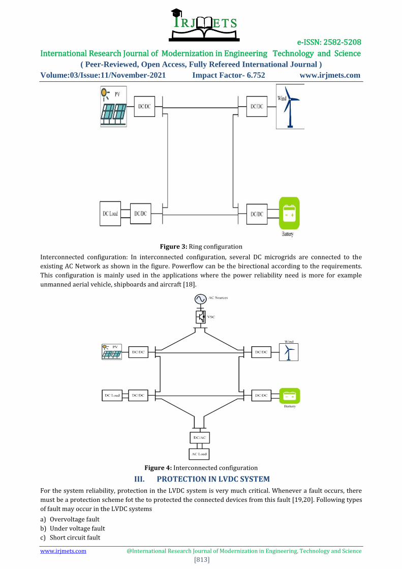
Figure 3: Ring configuration
Interconnected configuration: In interconnected configuration, several DC microgrids are connected to the
existing AC Network as shown in the figure. Powerflow can be the birectional according to the requirements.
This configuration is mainly used in the applications where the power reliability need is more for example
unmanned aerial vehicle, shipboards and aircraft [18].
Figure 4: Interconnected configuration
III. PROTECTION IN LVDC SYSTEM
For the system reliability, protection in the LVDC system is very much critical. Whenever a fault occurs, there
must be a protection scheme fot the to protected the connected devices from this fault [19,20]. Following types
of fault may occur in the LVDC systems
a) Overvoltage fault
b) Under voltage fault
c) Short circuit fault

e-ISSN: 2582-5208 International Research Journal of Modernization in Engineering Technology and Science
( Peer-Reviewed, Open Access, Fully Refereed International Journal )
Volume:03/Issue:11/November-2021 Impact Factor- 6.752 www.irjmets.com
www.irjmets.com @International Research Journal of Modernization in Engineering, Technology and Science
[814]
Short circuit fault is further classified into two types of fault.
a) Line to Line fault
b) Line to Ground fault
In [21], paper addresses the problem of over and under voltage as well as short circuit in Low Voltage DC
(LVDC) system. Disturbance caused by these faults can result in damage of components, loss of energy and can
heavily effect the operation of delicate medical and industrial equipment. This paper describes the protection
schemes, fault calculations and circuit modeling against over and under voltage as well as short circuit in
LVDC system. Solid state switches are used as breaker in circuit model. Finally, validity of the calculations and
results are verified by using MATLAB/Simulink software.
In [22], the protection scheme for the LVDC distribution system is presented. The possible fault cases and
protection requirements are also presented. The future challenge is the integration of protection functions to
the power electronic devices to reduce system costs and to decrease protection system complexity
IV. EXISTING PROTECTION SCHEME
Mehdi Monadi [23], proposed a centralized protection scheme for MVDC (Medium Voltage DC) type
microgrids. The proposed scheme has a communication assisted mechanism for fault detection, along with a
centralized coordinator for the protection. It also has a fault isolation technique that uses the minimum number
of DC circuit breakers. The proposed scheme not only has fault detection and fault isolation techniques but also
a backup protection is there. A backup protection gets activated when the communication falls. The main
components of the proposed scheme are following
1. For fault detection and location, differential based relay is used.
2. To protect the VSC connected to the host network and DG (Distributed Generator), overcurrent relay was
being used.
3. For the supervision of the adaptive devices and making them adaptive to the operating conditions, a
centralized protection unit is implemented.
4. Combination of DCCB and the isolators are there for the Practical Computation of d i /d t for High-Speed
Protection of DC Microgrids he fast fault interruption.
The above mentioned technique have been HIL simulated, and the result obtained found to be optimally fast for
the safety of the VSCs. The time required to restore the network is found to be with 100ms to 300ms.
Chunpeng Li et al [24] in the paper shows that the major challenge that the DC systems has in the short
circuited faults. This problem can be addressed by isolating the faulty networks just before the discharge of the
DC side capacitors. A new method has been proposed to get the new high speed distance protection schemes
using the rate of change of current. In this method, two techniques are presented that optimizes the rate of
change of fault current transients using the MATLAB model of DC microgrid with injected measurement noise.
1. The first method derives the optimized selection of the sampling frequency of the current measurement
signal and at the same time minimizing the noise pickups. In this method the effect of noise is constrained.
Computational step is M times the sampling period ∆T , the equation of computation is represented as
equation 1
[ ] [ ]
…………………..(1)
have been set of 25, 100 and 400 micro sec. to test the sensitivity of the approach. As shown in the
figure . the effect of noise is reduced as the sampling time increases.

e-ISSN: 2582-5208 International Research Journal of Modernization in Engineering Technology and Science
( Peer-Reviewed, Open Access, Fully Refereed International Journal )
Volume:03/Issue:11/November-2021 Impact Factor- 6.752 www.irjmets.com
www.irjmets.com @International Research Journal of Modernization in Engineering, Technology and Science
[815]
Figure 5: Effect of increased sampling time
The larger time steps are good for the noise suppression but not for the accuracy. It gave rise to the tradeoff
between noise suppression and accuratc. An optimum sampling time is to be used. A method to get the
optimum time step is also discussed in the paper. According to the discussed method the optimum sampling
interval was found to be just greater than the 19.6 micro second.
2. The second method uses the Finite Impulse Response filter, for conditioning of the signal just before the
di/dt computation. The RLC current and voltage response is given below
………….(2)
α is the damping factor, ωd is the damped resonant frequency. VCf is the voltage across the capacitor. Appling
a fourier transform on the above mentioned equation will give rise to the frequency distribution of the fault
current signal.
………… (3)
The obtained result in the paper shows that the main frequency content is found to be in lower band. While
designing a low pass filter the cut-off frequency is found to be
………… (4)
The designed FIR filter gives the following frequency response

e-ISSN: 2582-5208 International Research Journal of Modernization in Engineering Technology and Science
( Peer-Reviewed, Open Access, Fully Refereed International Journal )
Volume:03/Issue:11/November-2021 Impact Factor- 6.752 www.irjmets.com
www.irjmets.com @International Research Journal of Modernization in Engineering, Technology and Science
[816]
Figure 6: FIR filter response
Further the paper shows that the derivative based over current protection is found to be faster than the
threshold based over current protection.
Khaled et al. [25] uses the travelling wave approach for the fault detection and location finding. In this paper a
travelling wave is studied that used to be generated from the different types of fault in the MVDC circuits. The
proposed method analyses the frequency of the generated travelling wave rather than the arrival time. The
microgrid has been modelled in the PSCAD/ EMTDC. The underground cables has been modelled as the
distributed parameters that depends on the frequency. The telegrapher’s equation has been used to describe
current and voltage travelling wave in the frequency domain
………… …(5)
…………………(6)
Vtw and Itw are the functions of the frequency w. These are the Fourier transform of the voltage and currents
respectively. Solution of Vtw and Itw are given in following equation
…………. (7)
…………. (8)
Vi , Vr, Ii and Ir are the incident and reflective voltages and currents respectively. X is the distance travelled by
the wave. ϒ is the propagation constant. The proposed scheme based on the frequency analysis of the fault
generated travelling wave detects the fault within 128 micro second. The proposed scheme does not uses any
communication systems and only the local measurements has been taken, this process avoid any issues that
may arise due to the communication systems. In this paper a comparison has been done with the previous
methods and the proposed method has been found to be better in terms of selectivity, sensitivity and the
accuracy.
Dong Wang et al. [26] proposes a method based on the both voltage change and the current change. The main
focus of the proposed method is to reduce the level of the fault current within the distribution network. The
result of the multiplication of the both, current change and voltage change is used as a coordination for the
protection on the different relays. The model is implemented in PSCAD/ EMTDC simulator. The used
distribution network is shown in the figure

e-ISSN: 2582-5208 International Research Journal of Modernization in Engineering Technology and Science
( Peer-Reviewed, Open Access, Fully Refereed International Journal )
Volume:03/Issue:11/November-2021 Impact Factor- 6.752 www.irjmets.com
www.irjmets.com @International Research Journal of Modernization in Engineering, Technology and Science
[817]
Figure 7: Distribution network under test
Limiting the fault current level also give the more time to the overcurrent based protection schemes to operate.
This limited level also support the system to withstand the thermal impact. Flow chart of the proposed scheme
is shown in the figure
Figure 8: Flow chart of the proposed scheme
The paper also gave the future scope of the current limiting techniques to be widely used.
V. CONCLUSION
The application of Low Voltage DC networks are vast and it is the main component of the modern day
microgrid. Different type of fault may occur inside such networks. This review paper highlighted the basic
architecture of the DC network. Faults in the DC networks were also reviewed. Over-voltage, under voltage and
short circuit fault were reviewed. Result of previous protection scheme for DC network were done. In future,
more advance controllers can be design to cate the faults present in the LVDC Networks.
VI. REFERENCES
[1] Commission, E. DIRECTIVE OF THE EUROPEAN PARLIAMENT AND OF THE COUNCIL on the
promotion of the use of energy from renewable sources (recast); 2017; Vol. COM(2016);
[2] Oudalov, A.; Degner, T.; Overbeeke, F. van; Yarza, J.M. Microgrids; Hatziargyriou, N., Ed.; John Wiley
and Sons Ltd: Chichester, United Kingdom, 2013; ISBN 9781118720677
[3] 3. Ding, G.; Gao, F.; Zhang, S.; Loh, P.C.; Blaabjerg, F. Control of hybrid AC/DC microgrid under islanding
operational conditions. J. Mod. Power Syst. Clean Energy 2014, 2, 223–232
[4] 4. Bullich-Massagué, E.; Díaz-González, F.; Aragüés-Peñalba, M.; Girbau-Llistuella, F.; Olivella-Rosell, P.;
Sumper, A. Microgrid clustering architectures. Appl. Energy 2018
e-ISSN: 2582-5208 International Research Journal of Modernization in Engineering Technology and Science
( Peer-Reviewed, Open Access, Fully Refereed International Journal )
Volume:03/Issue:11/November-2021 Impact Factor- 6.752 www.irjmets.com
www.irjmets.com @International Research Journal of Modernization in Engineering, Technology and Science
[818]
[5] AlLee, G.; Tschudi, W. Edison Redux: 380 Vdc Brings Reliability and Efficiency to Sustainable Data
Centers. IEEE Power Energy Mag. 2012, 10, 50–59.
[6] Kwasinski, A. Quantitative Evaluation of DC Microgrids Availability: Effects of System Architecture
and Converter Topology Design Choices. IEEE Trans. Power Electron. 2011, 26, 835–851
[7] ABB Technical Application Papers No.14 Faults in LVDC microgrids with front-end converters. 2015
[8] European Telecommunication Standards Institute Part3: ETSI EN 300 132-3-1; 2011; Vol. 1, pp. 1–31
[9] Wu, P.; Huang, W.; Tai, N.; Liang, S. A novel design of architecture and control for multiple microgrids
with hybrid AC/DC connection. Appl. Energy 2018, 210, 1002–1016.
[10] Saidi, A.; Chellali, B. Simulation and control of Solar Wind hybrid renewable power system. In
Proceedings of the 2017 6th International Conference on Systems and Control (ICSC); IEEE, 2017; pp.
51–56.
[11] Cano, A.; Jurado, F.; Sanchez, H.; Castaneda, M.; Fernandez, L.M. Sizing and energy management of a
stand-alone PV/hydrogen/battery-based hybrid system. In Proceedings of the International Symposium
on Power Electronics Power Electronics, Electrical Drives, Automation and Motion; IEEE, 2012; pp.
969–973
[12] Wu, P.; Huang, W.; Tai, N.; Liang, S. A novel design of architecture and control for multiple microgrids
with hybrid AC/DC connection. Appl. Energy 2018, 210, 1002–1016.
[13] Saidi, A.; Chellali, B. Simulation and control of Solar Wind hybrid renewable power system. In
Proceedings of the 2017 6th International Conference on Systems and Control (ICSC); IEEE, 2017; pp.
51–56
[14] Zare, F. Modular Multi-Parallel Rectifiers (MMR) with two DC link current sensors. In Proceedings of
the 2016 IEEE Energy Conversion Congress and Exposition (ECCE); IEEE, 2016; pp. 1–7.
[15] Lindman, P.; Thorsell, L. Applying distributed power modules in telecom systems. IEEE Trans. Power
Electron. 1996, 11, 365–373
[16] 19. Balog, R.S.; Krein, P.T. Bus Selection in Multibus DC Microgrids. IEEE Trans. Power Electron. 2011,
26, 860–867
[17] Kumar, D.; Zare, F.; Ghosh, A. DC Microgrid Technology: System Architectures, AC Grid Interfaces,
Grounding Schemes, Power Quality, Communication Networks, Applications, and Standardizations
Aspects. IEEE Access 2017, 5, 12230–12256
[18] Burt, G.M.; Galloway, S.J.; Fletcher, S.D. a.; Norman, P.J. Determination of protection system
requirements for DC unmanned aerial vehicle electrical power networks for enhanced capability and
survivability. IET Electr. Syst. Transp. 2011, 1, 137–147
[19] Mackay, L., Blij, N. H. V. D., Ramirez-Elizondo, L., & Bauer,P.(2017). Toward the universal DC distribution
system. Electric Power Components and Systems, 45(10), 1032-1042.
[20] Seggewiss, G., Dai, J., & Fanslow, M. (2015). Synchronous motorson grinding mills: The different
excitation types and resulting performance characteristics with VFD control for new or retrofit
installations. IEEE Industry Applications Magazine, 21(6), 60-6
[21] Sheikh Muhammad Aaqib, Protection Schemes for Low Voltage DC Networks, Proc. of the 1st
International Conference on Electrical, Communication and Computer Engineering(ICECCE) 24-25 July
2019, Swat, Pakistan
[22] Patil, Ganesh; Satarkar, M. F. A. R. (2014). [IEEE 2014 International Conference on Power Automation
and Communication (INPAC) - Amravati, India (2014.10.6-2014.10.8)] 2014 International Conference
on Power, Automation and Communication (INPAC) - Autonomous protection of low voltage DC
microgrid. , (), 23–26. doi:10.1109/inpac.2014.6981129 [M. Saisho, T. Ise, and K. Tsuji, “Configuration
of DC loop type quality control center,” in Proc. Power Convers. Conf., 2002, vol. 2, pp. 434–439.
[23] Mehdi Monadi, Catalin Gavriluta, Alvaro Luna, Jose Ignacio Candela, Pedro Rodriguez, “Centralized
Protection Strategy for Medium Voltage DC Microgrids", IEEE Transaction on Power Delivery, Vol. 32,
2017.
e-ISSN: 2582-5208 International Research Journal of Modernization in Engineering Technology and Science
( Peer-Reviewed, Open Access, Fully Refereed International Journal )
Volume:03/Issue:11/November-2021 Impact Factor- 6.752 www.irjmets.com
www.irjmets.com @International Research Journal of Modernization in Engineering, Technology and Science
[819]
[24] Chunpeng Li, Puran Rakhra, Patrick Norman, Pawel Niewczas, Graeme Burt, Paul Clarkson, “Practical
Computation of d i /d t for High-Speed Protection of DC Microgrids", IEEE Second International
Conference on DC Microgrids (ICDCM), 2017
[25] Khaled Saleh, et al. “Fault detection and location in medium-voltage DC microgrids using travelling-
wave reflections", IET Renewable Power Generation, 14 (4), 2020.
[26] Dong Wang, Abdullah Emhemed, and Graeme Burt, “A Novel Protection Scheme for an LVDC
Distribution Network With Reduced Fault Levels”, 978-1-5090-4479-5/17/$31.00 ©2017 IEEE.