aa-stacked bilayer square ice between graphene layerslammps.ir/uploads/docs/m5-riphcedenh.pdf ·...
TRANSCRIPT
PHYSICAL REVIEW B 92, 245428 (2015)
AA-stacked bilayer square ice between graphene layers
M. Sobrino Fernandez Mario,1 M. Neek-Amal,2,* and F. M. Peeters1
1Departement Fysica, Universiteit Antwerpen, Groenenborgerlaan 171, B-2020 Antwerpen, Belgium2Department of Physics, Shahid Rajaee Teacher Training University, Lavizan, Tehran 16788, Iran
(Received 26 August 2015; revised manuscript received 6 November 2015; published 17 December 2015)
Water confined between two graphene layers with a separation of a few A forms a layered two-dimensionalice structure. Using large scale molecular dynamics simulations with the adoptable ReaxFF interatomic potentialwe found that flat monolayer ice with a rhombic-square structure nucleates between the graphene layers whichis nonpolar and nonferroelectric. We provide different energetic considerations and H-bonding results thatexplain the interlayer and intralayer properties of two-dimensional ice. The controversial AA stacking foundexperimentally [Algara-Siller et al., Nature (London) 519, 443 (2015)] is consistent with our minimum-energycrystal structure of bilayer ice. Furthermore, we predict that an odd number of layers of ice has the same latticestructure as monolayer ice, while an even number of ice layers exhibits the square ice AA stacking of bilayer ice.
DOI: 10.1103/PhysRevB.92.245428 PACS number(s): 73.22.Pr, 64.70.Nd, 71.15.−m
I. INTRODUCTION
The phase diagram of water and its extraordinary propertieshave been an interesting topic of research in biology, chemistry,and physics for many decades. Depending on the hydrophobicconfinement width several two-dimensional ice structures canbe formed [1–4]. Different theoretical methods, e.g., moleculardynamics (MD) simulations using different force fields [1,4],density functional theory [5], and Monte Carlo simulations[6], have been used to study ice formation in the presenceof high pressure. In particular, monolayer ice was proposedby Zangi and Mark [1,2] using MD simulations by applying afive site and tetrahedrally coordinated model, i.e., TIP5P. Theyconfined water between two parallel plates and applied a highlateral pressure (Pl) of about 1–2 kbar and found a nonflatmonolayer of ice.
Recently, it was found experimentally that confined wa-ter exists as a quasi-two-dimensional layer with differentproperties than those of bulk water [7,8]. Graphene, thetwo-dimensional allotrope of carbon [9], was used in a recentexperiment to confine water [8] into monolayer, bilayer, andthree layers. Using transmission electron microscopy (TEM)a square lattice structure was observed. The lateral pressurefor confining water between two sheets of graphene can beestimated [8,10,11] to be about 1 GPa using the van der Waals(vdW) adhesive energy between two layers which is typicallyaround 20 meV A−2. This experiment was supported by MDsimulations that showed that by increasing the pressure, bilayersquare ice (three layer ice) with a lattice constant of 2.82 Anucleates where the graphene layers are separated by a distanceh = 9 A (11.5 A) [8]. However, the MD simulations failedto reproduce the experimental found AA stacking of bilayerice. Ab initio calculations found that monolayer ice confinedbetween hydrophobic graphene layers can be rippled or flat,depending on the confinement width and lateral pressure [5].However, this DFT study is based on a small supercell whichtherefore missed structures that involve more than four watermolecules.
*Corresponding author: [email protected]
Using the reactive bond order potential we reveal newphysics of confined ice between two graphene layers. Weperformed annealing MD simulations starting from hightemperature, i.e., 400 K and found the low-temperatureminimum-energy configuration, and determined the structureof monolayer, bilayer, and three layer ice. We evaluate thedifferent energy terms, charge distribution, and hydrogenbond strength of confined water. The ReaxFF potential allowsfor different bond formations and takes into account thepolarization of charge within the molecules. The studiedsystems are found to be all flat, nonpolar, and nonferroelectricwhere the microscopic structure depends on the number of icelayers. We found a flat structure for confined ice and estimatedthe vdW energy between two ice layers.
II. METHOD AND MODEL
We employed molecular dynamics (MD) simulations usingreactive force field (ReaxFF) potentials [12] in the well-knownlarge-scale atomic/molecular massively parallel simulator“LAMMPS” [13]. The ReaxFF potentials used [14] accountfor possible bond formation and bond dissociation of differentbond orders. It also contains Coulomb and van der Waalspotentials to describe nonbond interactions between all atoms.One of the main advantages of ReaxFF is that it calculates thepolarization of charge within the molecules which is achievedby using electronegativity and hardness parameters based onthe electronegativity equalization method and charge equili-bration (QEq) methods. Therefore, we believe that ReaxFF isa better candidate to simulate water and the correspondinginteraction between water and graphene. Furthermore, theReaxFF potential allows bond extension/contraction in wateras well as angle bending and charge relaxation over each atom.This is in contrast to the traditional force fields for water,e.g., SPC and TIP4P [15] (a rigid planar four-site interactionpotential for water) that keep the water molecules rigid duringMD simulations.
The computational unit cell contains 34 848 carbon atomsand 5700 × n water molecules where n is the number ofice layers. These numbers have been chosen so that thegraphene lattice is commensurate with the water latticewhen performing simulations with periodic boundaries. To
1098-0121/2015/92(24)/245428(5) 245428-1 ©2015 American Physical Society

SOBRINO FERNANDEZ MARIO, NEEK-AMAL, AND PEETERS PHYSICAL REVIEW B 92, 245428 (2015)
−15
−10
−5
0
5
10
15
−15 −10 −5 0 5 10 15
Y (
Å)
X (Å)
FIG. 1. (Color online) The top (a) and side (b) view of the relaxed monolayer of ice between two graphene layers [red (grey) circles indicateO(H) atoms]. The corresponding (c) radial distribution function for O-O distances and (d) local dipoles of the individual water molecules.
match two different lattice parameters in a simulation boxthe following equation should hold: aGEm = aOOn, wherethe lattice constants aOO = 2.83 A and aGE = √
3/2aCC
and m and n should be integer numbers. Before startingthe minimization we do an annealing MD simulation byperforming a NPT simulation starting at 400 K and endingat 0 K, in order to find the true simulation box size and O-Odistances. Annealing was done using a Nose-Hoover barostat,with a cooling rate of 8 K/ps and a damping constant of 0.1ps. The high starting temperature guarantees that the O atomsand H bonds can find their minimum-energy configurationsduring the slow annealing process. Then, the total energyis minimized using the iterative conjugate gradient (CG)scheme.
A. Monolayer of ice
We start from a random distribution for the H bonds of thewater molecules which are distributed between two graphenelayers in a dense square structure, with O-O distance equal to2.8 A. The initial O-O distance is set to have the experimentallyobserved density for confined ice but during annealing, whichwe start from 400 K, the positions are allowed to change. Thegraphene layers are rigid and separated by a fixed distance of6.5 A having AB stacking. However, the results for the waterlayer are independent of the exact stacking configuration ofthe graphene layers. By minimizing the potential energy, wefound a flat rhombic-square lattice structure; see Fig. 1. Theside view of the minimum-energy configuration is shown inFig. 1(a) which is a flat monolayer of ice with successive
arrangements of square and rhombic building blocks; seeFig. 1(b). If the O atoms remain in the same plane, the H atomsshould also be in that plane in order to preserve the symmetry.The other possibility would be a buckled (puckered) structurewhich results in nonflat ice [1] (which was not found with oursimulations) [16]. Our results are partially in agreement withab initio results where Corsetti et al. [5] used nonlocal vdWexchange correlations and scanned both the confinement sizeand lateral pressure. However, their unit cell (called Ab/Cd)was too small, i.e., it contained only four water molecules,in order to find the aforementioned asymmetry effect. Ourfound structure for monolayer ice is in agreement with theMD simulation results using the SPC/E model [8]. In fact theTEM result of the recent experiment [8] is not a perfect squarelattice layer [17].
The crystalline structure and lattice constant of monolayerice can be determined from the radial distribution function(RDF); see Fig. 1(c). We found the O-O distance to bea = 2.84 ± 0.01 A. The obtained lattice constant is in goodagreement with the experimental value of a = 2.81 ± 0.02 A.The angle “H-O-H” is found to be θ = 106.31 ± 0.03◦ andis identical for all H-O-H bonds. The H-bonding energy isabout −0.16 eV/water (−15.43 kJ mol−1) for each watermolecule which is in the range of the H-bond energy of bulk ice[18], i.e., −(13–32) kJ mol−1. It is worth mentioning that thevdW energy stored in the system is EvdW = 2.43 eV/atomwhich is positive and the Coulomb energy is Ecoulomb =−0.56 eV/atom which is negative. These numbers show thatin dense ice the O atoms repel each other strongly (note thata = rOO ≈ 2.8 A lies in the repulsion region of the vdW
TABLE I. Different energy contributions to the minimized-energy configurations for mono (g.ice.g), bilayer (g.ice.ice.g), and trilayer(g.ice.ice.ice.g) water confined between two graphene layers.
H (A) Ecoulomb (eV/atom) EV dW (eV/atom) EHB (eV/water) a = roo = (A) d (A) c (A)
g.ice.g 6.5 −0.56 2.43 −0.16 2.84 ± 0.01 3.25 ± 0.01 0g.ice.ice.g 9 −0.86 2.07 −0.13 2.84 ± 0.01 2.88 ± 0.01 3.24 ± 0.01g.ice.ice.ice.g 11.5 −0.94 1.82 −0.16 2.89 ± 0.02 2.70 ± 0.01 3.05 ± 0.01
245428-2

AA-STACKED BILAYER SQUARE ICE BETWEEN . . . PHYSICAL REVIEW B 92, 245428 (2015)
−6.4
−6.3
−6.2
−6.1
−6
−5.9
−5.8
0 0.2 0.4 0.6 0.8 1 1.2 1.4 1.6 1.8 2
E (
eV/a
tom
)
Electric Field (V/Å)
FIG. 2. (Color online) Energy of an ice monolayer relaxed be-tween two graphene layers when applying an in-plane electric fieldalong the direction of the arrow (left inset). Note the change of theH-bond orientation (right inset).
energy function [19]). In Table I, we list all relevant quantitiesfor the different studied systems.
The corresponding local dipoles of the water molecules inthe minimum-energy configuration are shown by the arrows inFig. 1(d). Interestingly, the net dipole is zero and the systemis nonferroelectric which is in agreement with ab initio results[5] and is in disagreement with the TIP5P model prediction[20]. We were able to deform the H-bond orientations using anin-plane electric field of about 1 V/A (see Fig. 2). As shown inFig. 2, by increasing the electric field (along the direction of theshown arrow in the inset of Fig. 2) from zero to around |E| � 1V/A we find a structural transition from the minimum-energyconfiguration with zero dipole moment to a new higher energyconfiguration with a net nonzero dipole moment, i.e., the localdipoles of the water molecules rotate in the direction of theelectric field (see right inset of Fig. 2).
For nonpolar flat monolayer ice there are many possiblestructures. We made a detailed investigation of them andpresent the results of one of the most relevant ones. We per-formed additional MD annealing and minimization by startingfrom an initial configuration where the H bonds are randomlyoriented in three dimensions but have the same orientationfor each water molecule. We found that the minimum-energyconfiguration is a flat and polar structure which is shown inFig. 3. The potential energy of this structure is 10 meV/atomhigher than the nonpolar structure (Fig. 1). The vdW, Coulomb,and H-bond energy for the polar monolayer shown inFig. 3 are found to be Ecoulomb = −0.55 eV/atom, EvdW =2.48 eV/atom, and EHB = −0.14 eV/water respectively. TheO-O distance is a = 2.88 ± 0.02 A and the H-O-H angleequals θ = 106.6 ± +0.1◦. We also performed simulations forthe other possible polar structures proposed by Corsetti et al.[5] and found that all of them have higher energy than the oneshown in Fig. 1.
B. Bilayer square ice
Motivated by the experimental work of Algara-Siller et al.[8] a bilayer of ice confined between two rigid graphene layersseparated by h = 9 A was investigated. The minimum-energy
−15
−10
−5
0
5
10
15
−15 −10 −5 0 5 10 15
Y (
Å)
X (Å)
Dipole Moment
FIG. 3. (Color online) (a) A polar lattice of monolayer ice con-fined between two graphene layers which has about 10 meV/atomhigher energy than the nonpolar structure. (b) The correspondinglocal dipoles.
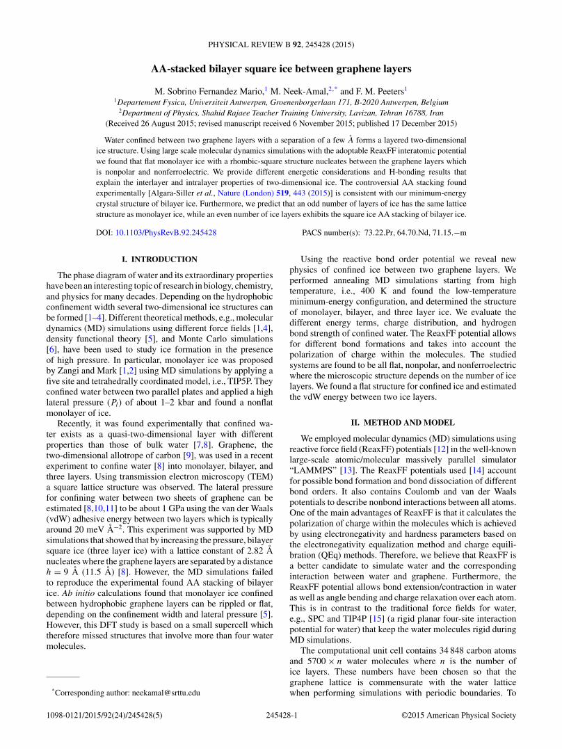
structure is shown in Figs. 4(a) and 4(c). Surprisingly, alsoin this case the layers are flat [see Fig. 4(a)] and each has aperfect square lattice for the O atoms [see Fig. 4(c)]. Using theradial distribution function for each layer we found the latticeconstant to be a = 2.84 ± 0.01 A. The radial distributionfunction for each ice layer is presented in Fig. 4(b) andare identical. The obtained angle H-O-H is found to beθ = 106.15 ± +0.02◦. Each layer has a net dipole that is inthe opposite direction with respect to the other layer. Thelatter makes the bilayer of ice nonpolar and nonferroelectric.The interlayer distance between the ice layers is found to bec = 3.24 ± 0.01 A which is in disagreement with the SPC/Emodel which obtained a ∼= c [8]. Our finding for “c” is inthe range of vdW adhesion between two ordinary neutrallayers, e.g., the two graphene layers. The H-bonding, vdW,and the Coulomb energy are −0.13 eV/water, 2.07 eV/atom,and −0.86 eV/atom, respectively. It is interesting to note thatthe vdW energy here is lower than that of a single layer of icewhich is due to the extra adhesion between the two ice layers.Therefore we can estimate the vdW energy stored betweenthe ice layers as −0.41 eV/atom. This energetic analysis givesimportant insights about the physics of confined water betweentwo graphene layers.
The stacking of the two ice layers is not (perfect) AA stack-ing, i.e., the bottom layer has an in-plane shift of about 1.2 A
245428-3
SOBRINO FERNANDEZ MARIO, NEEK-AMAL, AND PEETERS PHYSICAL REVIEW B 92, 245428 (2015)
FIG. 4. (Color online) Relaxed bilayer ice between two graphene layers are shown in (a) side and (c) top view. In (b) the correspondingradial distribution function for O-O distances is shown. In the top view (c), the green dots refer to the TEM experiment [8]. The in-plane shiftbetween top and bottom layers is about 1.2 A.
[shown by the arrow in Fig. 4(c)] with respect to the top layer.The displacement of the O atoms with respect to each other isdue to the fact that the O atoms are negatively charged and thusrepel each other. Please note that the SPC/E model [8] predictsAB stacking for bilayer ice confined between two graphenelayers. However, the TEM images in the recent experiment [8],which are shown by green circles in the bottom right part of Fig.4(c), can be considered as the averaged positions of oxygenatoms in the top (red dots) and bottom layer (blue dots) of ourresults. We believe that the blue and red circles in reality vibratealong the black arrow shown in Fig. 4(c) resulting in a timeaveraged AA stacking in square ice. In order to investigate theimportance of the interaction between ice and graphene andto present an independent test, we performed an additionalMD minimization. We minimized the potential energy ofmonolayer ice with randomly distributed H bonds (even out ofplane) over a single layer of graphene at an initial distance of3.0 A. The minimum-energy configuration of ice is similar toFig. 1 with the distance between graphene and ice of 2.90 A.This shows that the interaction between graphene and an icelayer is stronger than the interaction between two ice layers,which are separated by c = 3.24 A and the interaction betweenthe two graphene layers even if they are at a distance of 9 A.
C. Trilayer ice
Finally, we turn our attention to the stacking and micro-scopic structure of confined three layer ice. By fixing twographene layers at a distance h = 11 A and performing an-nealing MD simulations, we found that each layer of the threelayer ice is nonpolar with a microscopic structure similar to thatof monolayer ice [see Fig. 1(b)]. The ice-graphene distance isfound to be d = 2.70 A ± 0.01 and the distance between eachof the ice layers is c = 3.05 A ± 0.01. The vdW, Coulomb, andH-bonding energy are Ecoulomb = −0.94 eV/atom, EvdW =1.82 eV/atom, and EHB = −0.16 eV/water respectively.
We found that it is energetically unfavorable to have an icelayer with a net dipole moment next to one with zero net polarmoment. Therefore, we conclude that for an odd number ofice layers each layer has the structure of confined monolayerice (each of them with a zero net dipole moment). Howevera system with an even number of ice layers confined betweengraphene will be comprised of pairs of layers where each pairhas a structure like bilayer ice (Fig. 5).
III. DISCUSSION AND CONCLUSIONS
In ordinary water the average distance between oxygenatoms is about 2.82 A [18] and for each water molecule twohydrogen bonds (H bonds) are randomly oriented resultingin an irregular network. The H bonds in liquid water havea lifetime of about 1–20 ps. Continuously bond formationand bond breaking takes place. The H bonds are stronger inhexagonal bulk ice (ordinary ice) though the O-O distanceis still 2.82 A but each water molecule takes part in fourtetrahedrally arranged H bonds [18], i.e., forming a regularnetwork with more room between the molecules yielding alower density. Moreover, the strength and orientation of theH bonds change when high pressure is applied. When wateris confined between hydrophobic walls (here two graphenelayers) in the presence of lateral pressure of about 1 GPa,monolayer ice is formed with an O-O distance of about 2.83 A[8]. Therefore, the spatial orientation of the H -bonds and theirstrength and rearrangement is a key factor which determinesthe structure of water and the different phases of ice in confinedmonolayer and few layer ice.
In typical three-dimensional (3D) ice structures, e.g., ice Ih,the electrostatic attraction between H and O atoms dominatesthe repulsion between the oxygens. However, in a densemonolayer (and few layer) ice, the electrostatic energy is notlarge enough to cancel the repulsive vdW energy and thusan external pressure is needed to keep the system stable. In
245428-4

AA-STACKED BILAYER SQUARE ICE BETWEEN . . . PHYSICAL REVIEW B 92, 245428 (2015)
FIG. 5. (Color online) Multilayer ice confined between graphene layers. The arrows indicate the net dipole moment in each layer.
fact, the high lateral pressure applied on confined water atroom temperature results in monolayer ice. These conditionsare equivalent to the water phase close to zero K (i.e., ice)but now at about 1 bar (or zero) as we studied. The multipleconfigurations of ice at high pressures that meet the rules ofabsolute zero temperature amounts to randomness, or in otherwords, entropy which is called residence entropy. Therefore theground-state configuration of water either at zero temperatureor high pressures strongly depends on the experimental proce-dure and details. This might be the reason for the observationof several different crystal structures as reported by differentgroups for confined ice using various methods [5,8,20]. Thelarge degree of freedom for the hydrogen bond strength and itsorientation gives the possibility to have several ice structures,either when the system is subjected to high pressure or iskept close to zero temperatures. This large degree of freedomis reduced when using the rigid model in MD simulationswhich may result in incorrect lattice structures. In our case,however, we find a layered structure which at zero temperature
is an entropyless structure. Three-dimensional water ice isthe first material for which residual entropy was proposedby Pauling [21]. By using MD simulations we showed thatthe Pauling proposal can be broken for a flat layer ofice.
For confined monolayer ice with a flat structure and zeronet dipole moment the H bonds should lie in the same plane.However, flat ice layers in nonpolar bilayer of ice nucleates asa square lattice with an almost AA stacking. We predict thatan odd (even) number of ice layers are stacks of monolayer(bilayer) ice. We found that the interaction between ice layersis weaker than that between ice and graphene which results ina shorter distance between ice and graphene.
ACKNOWLEDGMENTS
This work was supported by the ESF-Eurographene projectCONGRAN, and the Flemish Science Foundation (FWO-Vl).
[1] R. Zangi and A. E. Mark, Phys. Rev. Lett. 91, 025502(2003).
[2] R. Zangi and A. E. Mark, J. Chem. Phys 120, 7123(2004).
[3] J. Bai, C. Austen Angell, and X. Cheng Zeng, Proc. Natl. Acad.Sci. USA 107, 5718 (2010).
[4] W-H. Zhao, L. Wang, J. Bai, L-F. Yuan, J. Yang, and X. ChengZeng, Acc. Chem. Res. 47, 2505 (2014).
[5] F. Corsetti, P. Matthews, and E. Artacho, arXiv:1502.03750.[6] C. Vega, C. McBride, E. Sanz, and J. L. F. Abascal, Phys. Chem.
Chem. Phys. 7, 1450 (2005).[7] M. Ghosh, L. Pradipkanti, V. Rai, D. K. Satapathy, P.
Vayalamkuzhi, and M. Jaiswa, Appl. Phys. Lett. 106, 241902(2015).
[8] G. Algara-Siller, O. Lehtinen, F. C. Wang, R. R. Nair, U. Kaiser,H. A. Wu, A. K. Geim, and I. V. Grigorieva, Nature (London)519, 443 (2015).
[9] K. S. Novoselov, A. K. Geim, S. V. Morozov, D. Jiang, Y. Zhang,S. V. Dubonos, I. V. Grigorieva, and A. A. Firsov, Science 306,666 (2004).
[10] T. Bjorkman, A. Gulans, A. V. Krasheninnikov, and R. M.Nieminen, Phys. Rev. Lett. 108, 235502 (2012).
[11] S. P. Koenig, N. G. Boddeti, M. L. Dunn, and J. S. Bunch, Nat.Nanotechnol. 6, 543 (2011).
[12] A. C. T. van Duin, S. Dasgupta, F. Lorant, and W. A. Goddard,J. Phys. Chem. A 105, 9396 (2001); A. C. T. van Duin andJ. S. S. Damste, Org. Geochem. 34, 515 (2003).
[13] S. Plimpton, J. Comput. Phys. 117, 1 (1995).[14] K. Chenoweth, A. C. T. van Duin, and W. A. Goddard, J. Phys.
Chem. A 112, 1040 (2008).[15] J. L. Abascal and C. Vega, J. Chem. Phys. 123, 234505
(2005).[16] We emphasize that flat ice with a perfect square lattice cannot be
formed between two graphene layers because the two electronson the O atom form two covalent bonds with the H atoms whilethe four others make two H bonds with the neighbor waters (thisis responsible for the asymmetry), i.e., the H-O-H angle cannotbe 90◦.
[17] G. Algara-Siller, O. Lehtinen, F. C. Wang, R. R. Nair,U. Kaiser, H. A. Wu, A. K. Geim, and I. V. Grigorieva (privatecommunications).
[18] M. Chaplin, arXiv:0706.1355.[19] M. Neek-Amal, P. Xu, D. Qi, P. M. Thibado, L. O. Nyakiti,
V. D. Wheeler, R. L. Myers-Ward, C. R. Eddy, Jr., D. K. Gaskill,and F. M. Peeters, Phys. Rev. B 90, 064101 (2014).
[20] W.-H. Zhao, J. Bai, L.-F. Yuan, J. Yang, and X. C. Zeng, Chem.Sci. 5, 1757 (2014).
[21] L. Pauling, J. Am. Chem. Soc. 57, 2680 (1935).
245428-5