aadl and mdaaadl.sei.cmu.edu/aadlinfosite/linkeddocuments/gdweaponsjan205.pdf · aadl and mda early...
TRANSCRIPT

AADL and MDAEarly Experience Applied to Aircraft-Weapon Integration
Yves [email protected]
27 January 2005

2
Agenda
IntroductionA Weapons Management SystemEmbedded Systems: Solutions / TrendsPlug and Play Modeling ConceptsArchitecture Analysis and Description LanguageModel Driven Architecture

3
Introduction
The aircraft-weapon integration challenge is part of a larger integration problem, i.e.
Independent system-specific models often create unsolvable interoperability problems

4
Weapons Management Systems
http://www.fas.org/man/dod-101/sys/ac/f-18.htm
5
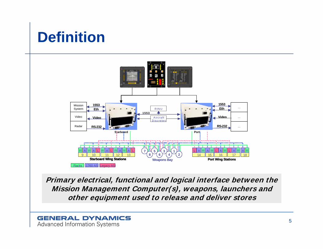
Definition
NAVIGATION SYSTEM BITSONOSAFE
KILLSAFE
INV
PORTWIC
EO/IRMSNSYS
CYZTACMC
NAV RAD TMPS A/CTAP
LATITUDE:LONGITUDE:
ALTITUDE:AIR SPEED:
HEADING:X VELOCITY:Y VELOCITY:Z VELOCITY:
AZIMUTH:PITCH:ROLL:
WANDER ANGLE:MESSAGE COUNT:
MESSAGE ERRORS:
N42:°32’31.008”W104°21’19.266”18000 FT295 KTS45.0°T0.1110.2220.33310.0°3.222°1.000°-45°23001
LATITUDE:LONGITUDE:
ALTITUDE:AIR SPEED:
HEADING:X VELOCITY:Y VELOCITY:Z VELOCITY:
AZIMUTH:PITCH:
ROLL:WANDER ANGLE:
MESSAGE COUNT:MESSAGE ERRORS:
N42:°32’31.008”W104°21’19.266”18000 FT295 KTS45.0°T0.1110.2220.33310.0°3.222°1.000°-45°35000
RINU1
BUSA
BUSB
RINU2
BUSA
BUSB
PortStarboard
XMIT
AIMSSS -3
PODAVAIL
SLMR PRELNCH
STA 11 STA 13 CO OP STA 14 STA 16
INV
POD CONTROLSLAM ER POST LAUNCH
SONOSAFE
KILLSAFE
SYNCOFF
XMITHI
STRTTTV
ACPTTGT
PREVTGT
TRCKMODE
RJCTTGT
TOOASUW
FULLSCRN
09/1258:59
12/1259:59
12/1259:59
12/1259:59
12/1259:59
09/1258:59
12/1259:59
12/1259:59
12/1259:59
12/1259:59
09/1258:59
12/1259:59
12/1259:59
12/1259:59
12/1259:59
ARM HAZARD
KILL READY
SONO DISABLE
MASTER ARM BOMB BAY SRCH PWR
ON
OFF
OFF
ARM HAZARD RESET
ON OPEN
CLOSED
JETTISON
JETTISON
JETTISON
JETTISON
WING ONLY
ARM HAZARD
KILL READY
SONO DISABLE
MASTER ARM BOMB BAY SRCH PWR
ON
OFF
OFF
ARM HAZARD RESET
ON OPEN
CLOSED
JETTISON
JETTISON
JETTISON
JETTISON
WING ONLYWING ONLYWING ONLY
MissionSystem
Video
Radar
1553
RS-232
Video
Eth
A irc ra ftD isc re tes
R IN U1553
Racks 1760 ASI Legacy ASI
Weapons Bay
5 3 176 4 28
5 3 176 4 28
Weapons Bay
5 3 176 4 28
5 3 176 4 28 18
RA17
L RA16
L RA15
RA14
L RA18
RA18
RA17
L RA17
L RA16
L RA15
RA15
RA14
L RA14
L RA
Port Wing Stations18
RA18
RA17
L RA17
L RA16
L RA15
RA15
RA14
L RA14
L RA18
RA18
RA17
L RA17
L RA16
L RA15
RA15
RA14
L RA14
L RA
Port Wing Stations9
R A10
LR A11
LR A12
R A13
LR A9
R A10
LR A11
LR A12
R A13
LR A
Starboard Wing Stations9
R A10
LR A11
LR A12
R A13
LR A9
R A10
LR A11
LR A12
R A13
LR A
Starboard Wing Stations9
R A10
LR A11
LR A12
R A13
LR A9
R A10
LR A11
LR A12
R A13
LR A
Starboard Wing Stations
…
…
…
1553
RS-232
Video
Eth
Primary electrical, functional and logical interface between theMission Management Computer(s), weapons, launchers and
other equipment used to release and deliver stores
6
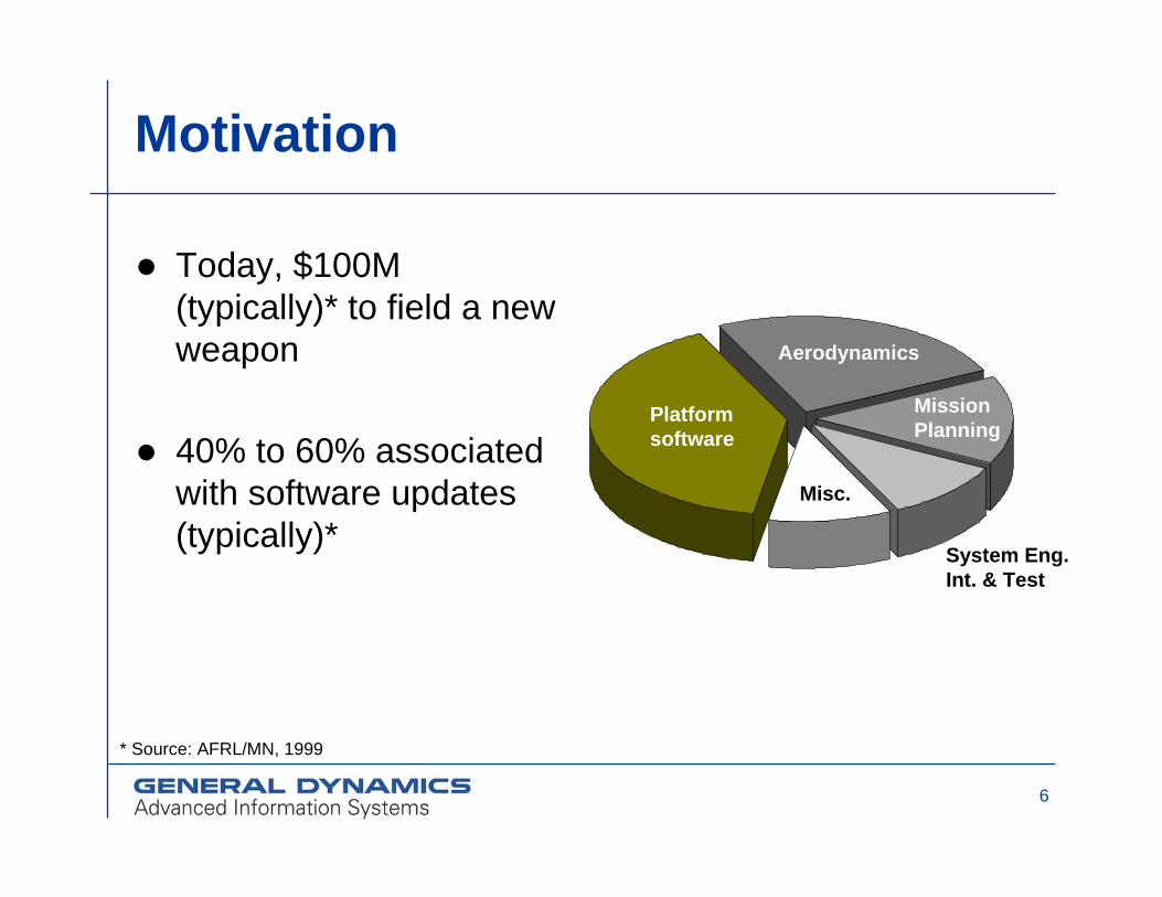
Motivation
Today, $100M (typically)* to field a new weapon
40% to 60% associated with software updates (typically)*
Platformsoftware
Aerodynamics
MissionPlanning
System Eng.Int. & Test
Misc.
* Source: AFRL/MN, 1999

7
Test and Integration Challenge
Platform PerspectiveProvide relevant functions and data
Observe resource, performance and timing constraints
Do not change platform software
Weapon Perspective *Identify/define relevant functions and data
Identify/define resource, performance and timing constraints
* Weapon software does change over time, which may impact the platform

8
Cost / Schedule Perspective (Notional)
Do not change platform software
Traditional New
Weapon 1
Weapon 2
Weapon 3
New WMS
$
WMS Development Costs
TraditionalNew
Weapon 1
Weapon 2
Weapon 3
Number of Months to Integrate a New Weapon
No need to take down the whole
squadron
9
State of the Art
Increasing complexity / decreasing productivity six (or fewer!) lines per day *
The inefficiency of the embedded software development process will prevent novel technologies from entering the marketplace in time
* Typical of embedded software industry

10
Embedded Systems: Solutions / Trends
Components Less dedication to specific functionsDesign - Improved abstractionSynthesis - Auto code generation Models - Assess before final implementationSpecification languages
Unambiguous representation of behavior and constraints - Rigorous semantics Widely accepted
11
Embedded Systems: Solutions / Trends
Semantic Interface SpecificationSyntax can be performed by any type of Interface Definition Language (IDL, XML) Assess semantic properties of an interface by an executable interface modelAssess interoperability by analyzing provided and required interfaces, and contractsAdapt interface to improve interoperability
AADL Semantic Interface Specification

12
Embedded Systems: Solutions / Trends
Dynamic Reflective SystemsChange internal behavior depending upon attached devicesCapable of integrating devices which provide new functionsCapable of providing unforeseen functionalityFoundation of aspect-oriented programming
13
Embedded Systems: Solutions / Trends
Applied to Aircraft-Weapon IntegrationIntegrate new capabilities within a given design space (domain)Prevent waiting for an aircraft upgrade cycle to integrate new weapons
ButLikely difficult to implement a dynamic system that meets performance constraintsAircraft-Weapon interface standards is a recent development, change is slow

14
The Plug and Play Concept
15
The Plug and Play Concept
Demonstrate interoperability at design timeIn terms of Functionality and Data
Open system approach via standardsIn terms of Non-Functional Quality Attributes
Safety, real-time, reliability, fault tolerance, security….
A system that can exchange information and services with multiple systems is more interoperable than one that can't
Assess the quality of interoperabilityFormulate strategies to improve interoperability
AADL SIS

16
Domain Model – Weapon Interface View
Missile
Apply powerInitialize
Set mission parametersSet missile modes etc
ReleaseJettison
IBIT
Get current configuration
WMS
Select Missile
Configure
Select State
Get Status
Platform
The WMS accepts generic missile commands.These are subsequently passed on to the missile.

17
Domain Model – Mission Interface View
WMSPlatform
Set Environment
Set Platform Characteristics
Set Target Acquisition
Set Mission Plan
The WMS offers mission services that are non-missile specific. Configuration data is subsequently passed on to the missile.
Missile
Configure
Configure
Configure
Configure

18
Domain Model - Life-Cycle View
Standby
Setup
Identification
Initialization
Identification
Initialization
Non-Operational
Ready
Mission Configure
Ready for Release
Status
IBIT ON
IBIT OFF
IBIT ON
IBIT OFF
Mission Configure
Ready for Release
Mission Committed
Prepare to Release
Release
Failed
Disable JettisonDisable Jettison
Executing Mission
Hung Flight
Detonation
Hung Flight
Detonation
Missile Selected
Start Mission
Off

19
Domain Model - Data View
Launch
Acceptability
Region
Weapon
20
State Machines
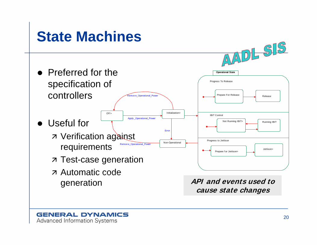
Preferred for the specification of controllers
Useful forVerification against requirementsTest-case generationAutomatic code generation
Operational State
Progress to Jettison
IBIT Control
Progress To Release
Operational State
Jettison>Prepare f or Jettison>
Running IBITNot Running IBIT>
Prepare For Release Release
Initialization>Of f >
Non-Operational
Apply _Operational_Power
Remov e_Operational_Power
Error
Remov e_Operational_Power
API and events used to cause state changes
21
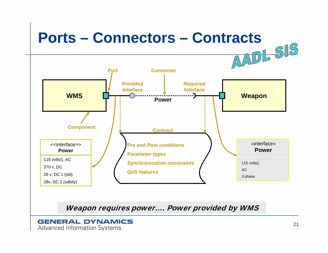
Ports – Connectors – Contracts
Weapon requires power…. Power provided by WMS
Power
Connector
Contract
Pre and Post conditions
Parameter types
Synchronization constraints
QoS features
Required Interface
Weapon
«interface»Power
115 volts()
AC
3 phase
<<interface>> Power
WMS
Component
Port
Provided Interface
115 volts(), AC
270 v, DC
28 v, DC 1 (std)
28v, DC 2 (safety)

22
Platform Challenge
Component models and supporting frameworks often rely on the specifics of the underlying platform
There is a need for techniques to handle functional and non-functional properties of components and systems

23
Non-Functional Properties
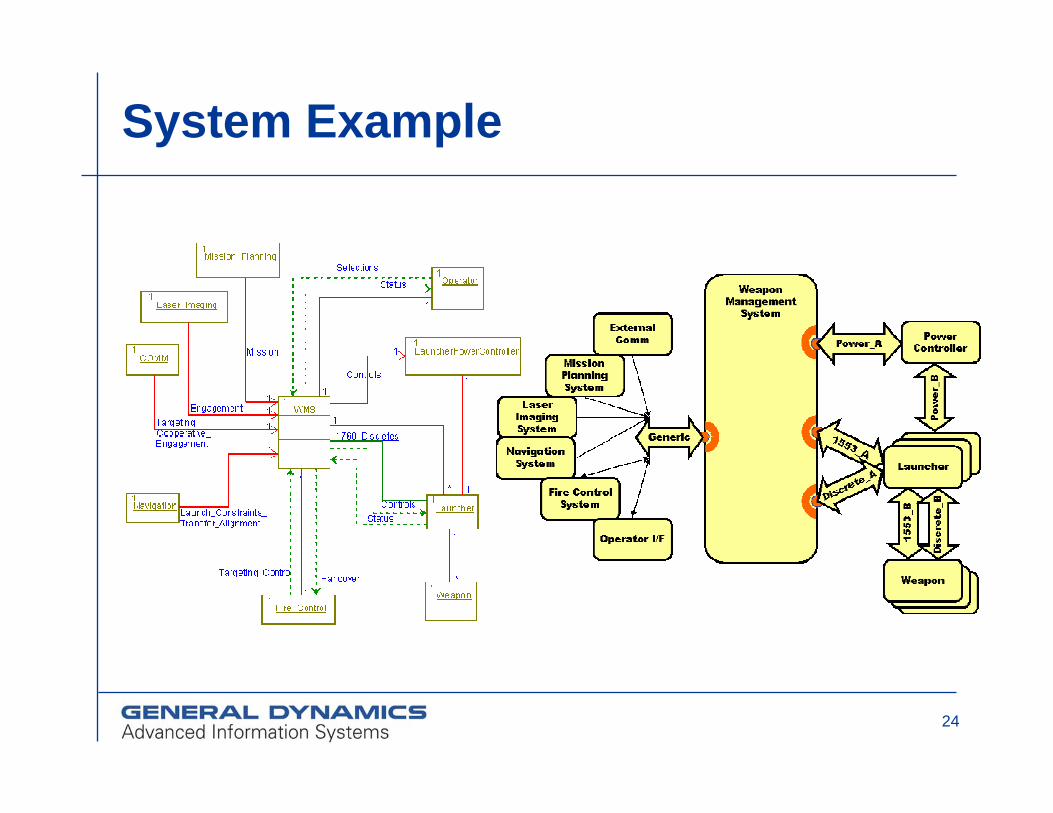
Architecture Analysis and Design Language (AADL)
MissileMissile
LauncherLauncher
WeaponManagement
SystemExternalComm
MissionPlanningSystem
LaserImagingSystem
NavigationSystem
Fire ControlSystem
Operator I/F
PowerController
Launcher
Weapon
1553_A
Discrete_A
Generic
Power_A
1553
_B
Pow
er_B
Dis
cret
e_B
MissileMissile
LauncherLauncher
WeaponManagement
SystemExternalComm
MissionPlanningSystem
LaserImagingSystem
NavigationSystem
Fire ControlSystem
Operator I/F
PowerController
Launcher
Weapon
1553_A
Discrete_A
Generic
Power_A
1553
_B
Pow
er_B
Dis
cret
e_B
24
System Example
25
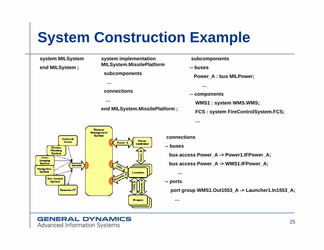
System Construction Examplesystem MILSystem
end MILSystem ;
subcomponents
-- buses
Power_A : bus MILPower;
…
-- components
WMS1 : system WMS.WMS;
FCS : system FireControlSystem.FCS;
…
connections
-- buses
bus access Power_A -> Power1.IFPower_A;
bus access Power_A -> WMS1.IFPower_A;
…
-- ports
port group WMS1.Out1553_A -> Launcher1.In1553_A;
…
system implementation MILSystem.MissilePlatform
subcomponents
…
connections
…
end MILSystem.MissilePlatform ;
26
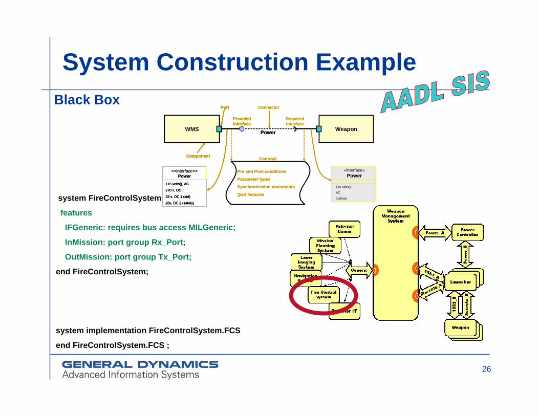
System Construction Example
system FireControlSystem
features
IFGeneric: requires bus access MILGeneric;
InMission: port group Rx_Port;
OutMission: port group Tx_Port;
end FireControlSystem;
system implementation FireControlSystem.FCS
end FireControlSystem.FCS ;
Black Box
Power
Connector
Contract
Pre and Post conditions
Parameter types
Synchronization constraints
QoS features
Power
Connector
Contract
Pre and Post conditions
Parameter types
Synchronization constraints
QoS features
Required Interface
Weapon
«interface»Power
115 volts()
AC
3 phase
Required Interface
Weapon
«interface»Power
115 volts()
AC
3 phase
<<interface>> Power
WMS
Component
Port
Provided Interface
115 volts(), AC
270 v, DC
28 v, DC 1 (std)
28v, DC 2 (safety)
<<interface>> Power
WMS
Component
Port
Provided Interface
115 volts(), AC
270 v, DC
28 v, DC 1 (std)
28v, DC 2 (safety)
WMS
Component
Port
Provided Interface
WMS
Component
Port
Provided Interface
115 volts(), AC
270 v, DC
28 v, DC 1 (std)
28v, DC 2 (safety)

27
System Construction Examplesystem WMS
features
-- Buses
IF1553_A: requires bus access MIL1553;
IFGeneric: requires bus access MILGeneric;
IFPower_A: requires bus access MILPower;
IFDiscrete_A: requires bus access MILDiscrete;
-- Ports
In1553_A: port group Rx_Port;
Out1553_A: port group Tx_Port;
InDiscrete_A: port group Rx_Port;
OutDiscrete_A: port group Tx_Port;
OutPower_A: port group Tx_Port;
InMission: port group Rx_Port;
OutMission: port group Tx_Port;
end WMS ;
port group Rx_Port
features
Rx: in data port;
inverse of Tx_Port
end Rx_Port;
port group Tx_Port
features
Tx: out data port;
end Tx_Port;
Black Box

28
WMS System Implementation Example
system implementation WMS.WMS
subcomponents
…
connections
…
modes
…
end WMS.WMS ;
subcomponents
--- processors
--- processes
--- bindings
connections
--- port groups
modes
MainMode: initial mode;
BackupMode: mode;
Factory
Pattern
29
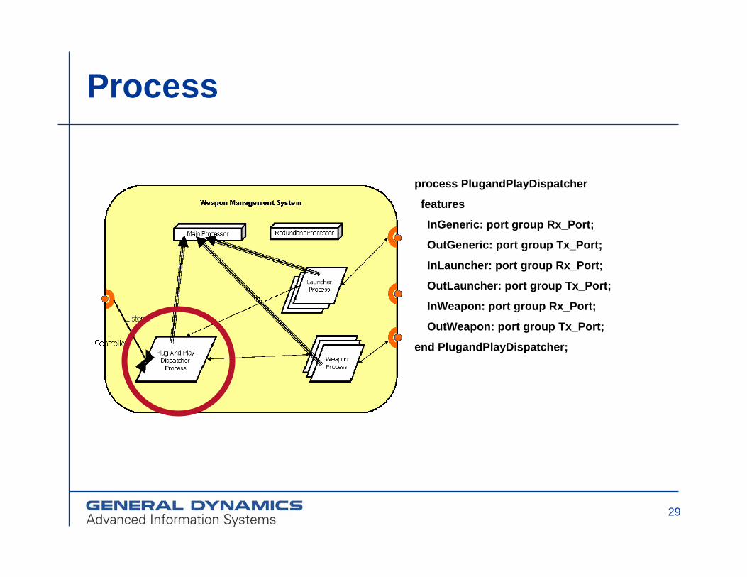
Process
process PlugandPlayDispatcher
features
InGeneric: port group Rx_Port;
OutGeneric: port group Tx_Port;
InLauncher: port group Rx_Port;
OutLauncher: port group Tx_Port;
InWeapon: port group Rx_Port;
OutWeapon: port group Tx_Port;
end PlugandPlayDispatcher;

30
Process Implementationprocess implementation PlugandPlayDispatcher.WMS
subcomponents
Bus_Listener: thread Listener.Bus_Listen;
PnP_Dispatcher: thread PnPDispatcher.WMS;
connections
port group InGeneric -> Bus_Listener.Bus_Listener;
port group Bus_Listener.Buffer_Update -> PnP_Dispatcher.InPnP;
port group PnP_Dispatcher.OutLauncher -> OutLauncher;
port group InLauncher -> PnP_Dispatcher.InLauncher;
port group PnP_Dispatcher.OutWeapon -> OutWeapon;
port group InWeapon -> PnP_Dispatcher.InWeapon;
end PlugandPlayDispatcher.WMS;
31
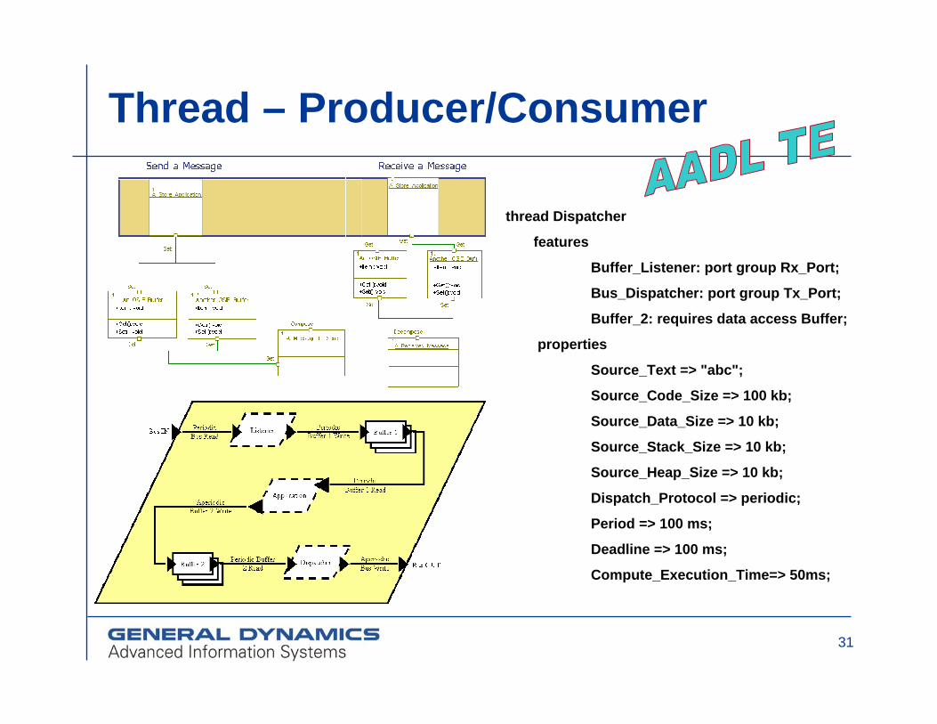
Thread – Producer/Consumer
thread Dispatcher
features
Buffer_Listener: port group Rx_Port;
Bus_Dispatcher: port group Tx_Port;
Buffer_2: requires data access Buffer;
properties
Source_Text => "abc";
Source_Code_Size => 100 kb;
Source_Data_Size => 10 kb;
Source_Stack_Size => 10 kb;
Source_Heap_Size => 10 kb;
Dispatch_Protocol => periodic;
Period => 100 ms;
Deadline => 100 ms;
Compute_Execution_Time=> 50ms;
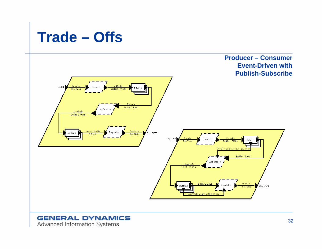
32
Trade – OffsProducer – Consumer
Event-Driven with Publish-Subscribe
33
Tools - OSATE
Open source AADL tool environment Software Engineering Institutewww.aadl.info
Set of plug-ins on top of Eclipsewww.eclipse.org
34
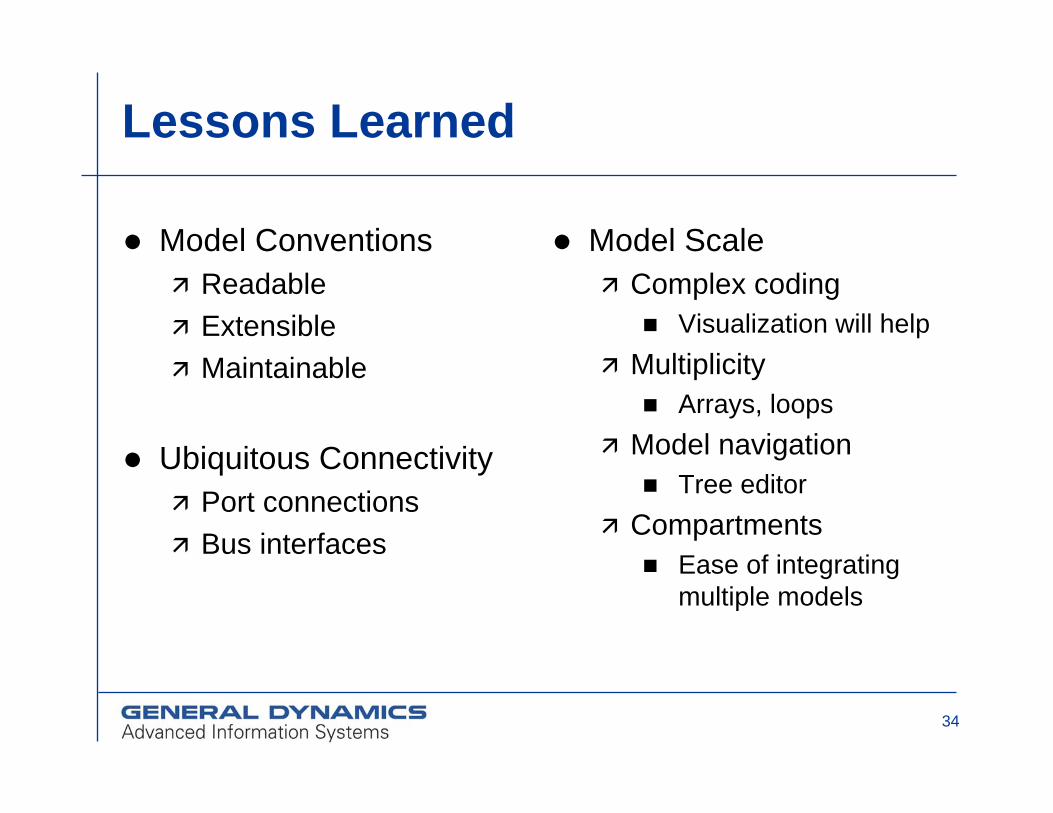
Lessons Learned
Model ConventionsReadableExtensibleMaintainable
Ubiquitous ConnectivityPort connections Bus interfaces
Model ScaleComplex coding
Visualization will helpMultiplicity
Arrays, loopsModel navigation
Tree editorCompartments
Ease of integrating multiple models

35
Future Work
Use / create OSATE analysis plug-insSchedulabilitySystem scalabilitySafetyEnd-to-end flow analysis
AADL support from UML vendors
36
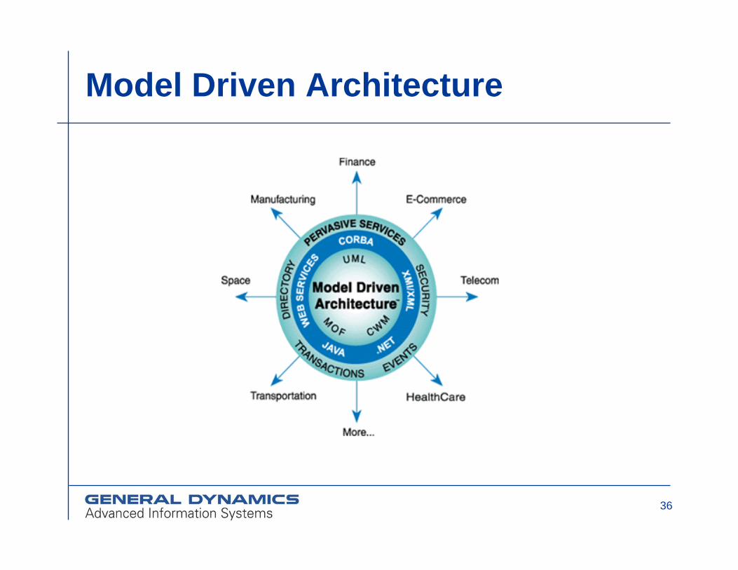
Model Driven Architecture

37
Approach to MDA
TE = Transformation Engine
CG = Code Generator
VE = Validation Engine
Domain
DomainRequirements
PlatformIndependent
Model
ProductInstance
PlatformRequirements
PlatformSpecificModel
ExecutableProduct
ExecutableSystem
CG
ValidatedProduct
ValidatedSystem
V
E
Application
ApplicationRequirements
PlatformIndependent
Model
Core ReusableCorporate
Assets
TE

38
Approach to MDA / AADL
ProductInstance
PlatformRequirements
AADLModel
TE
ProductInstance
PlatformRequirements
AADLModel
TE
ExecutableProduct
ExecutableSystem
CG
ExecutableProduct
ExecutableSystem
CG
ValidatedProduct
ValidatedSystem
AADL
ValidatedProduct
ValidatedSystem
AADL
Prove system propertiesProve system properties
ProductInstance
PlatformRequirements
UMLModel
ExecutableProduct
ExecutableSystem
CG
Derive system properties
39
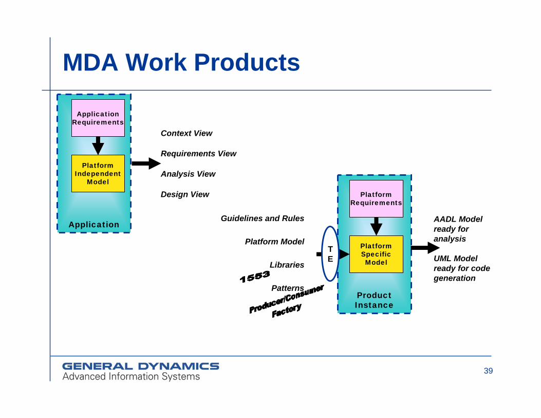
MDA Work Products
Application
ApplicationRequirements
PlatformIndependent
Model
Context View
Requirements View
Analysis View
Design View
ProductInstance
PlatformRequirements
PlatformSpecificModel
TE
Guidelines and Rules
Platform Model
Libraries
Patterns
AADL Model ready for analysis
UML Model ready for code generation

40
MDA / AADL Expectation
Traditional New
Weapon 1
Weapon 2
Weapon 3
New MWS
$
Development Costs for New Weapons
MDA
Traditional New
Weapon 1
Weapon 2
Weapon 3
New WMS
$
Development Costs for New Weapons
Without
MDA