abb iec & nema enclosed & 1-phase manual · pdf fileiec & nema enclosed starters...
TRANSCRIPT
3
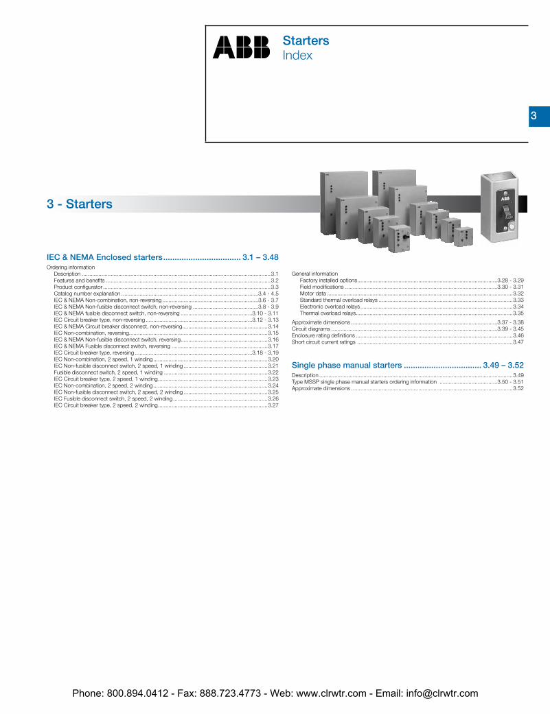
Starters
StartersIndex
IEC & NEMA Enclosed starters .................................. 3.1 – 3.48Ordering information
Description ............................................................................................................................3.1Features and benefits ............................................................................................................3.2Product configurator ..............................................................................................................3.3Catalog number explanation ..........................................................................................3.4 - 4.5IEC & NEMA Non-combination, non-reversing ...............................................................3.6 - 3.7IEC & NEMA Non-fusible disconnect switch, non-reversing ...........................................3.8 - 3.9IEC & NEMA fusible disconnect switch, non-reversing ...............................................3.10 - 3.11IEC Circuit breaker type, non-reversing ......................................................................3.12 - 3.13IEC & NEMA Circuit breaker disconnect, non-reversing ........................................................3.14 IEC Non-combination, reversing...........................................................................................3.15IEC & NEMA Non-fusible disconnect switch, reversing .........................................................3.16IEC & NEMA Fusible disconnect switch, reversing ...............................................................3.17IEC Circuit breaker type, reversing .............................................................................3.18 - 3.19IEC Non-combination, 2 speed, 1 winding ...........................................................................3.20IEC Non-fusible disconnect switch, 2 speed, 1 winding .......................................................3.21Fusible disconnect switch, 2 speed, 1 winding ....................................................................3.22IEC Circuit breaker type, 2 speed, 1 winding ........................................................................3.23IEC Non-combination, 2 speed, 2 winding ...........................................................................3.24IEC Non-fusible disconnect switch, 2 speed, 2 winding .......................................................3.25IEC Fusible disconnect switch, 2 speed, 2 winding ..............................................................3.26IEC Circuit breaker type, 2 speed, 2 winding ........................................................................3.27
3 - Starters
General informationFactory installed options ............................................................................................3.28 - 3.29Field modifications ....................................................................................................3.30 - 3.31Motor data ..........................................................................................................................3.32Standard thermal overload relays ........................................................................................3.33Electronic overload relays ....................................................................................................3.34Thermal overload relays .......................................................................................................3.35
Approximate dimensions ................................................................................................3.37 - 3.38Circuit diagrams .............................................................................................................3.39 - 3.45Enclosure rating definitions .......................................................................................................3.46Short circuit current ratings ......................................................................................................3.47
Single phase manual starters .................................. 3.49 – 3.52Description ...............................................................................................................................3.49Type MSSP single phase manual starters ordering information ......................................3.50 - 3.51Approximate dimensions ..........................................................................................................3.52
Phone: 800.894.0412 - Fax: 888.723.4773 - Web: www.clrwtr.com - Email: [email protected]
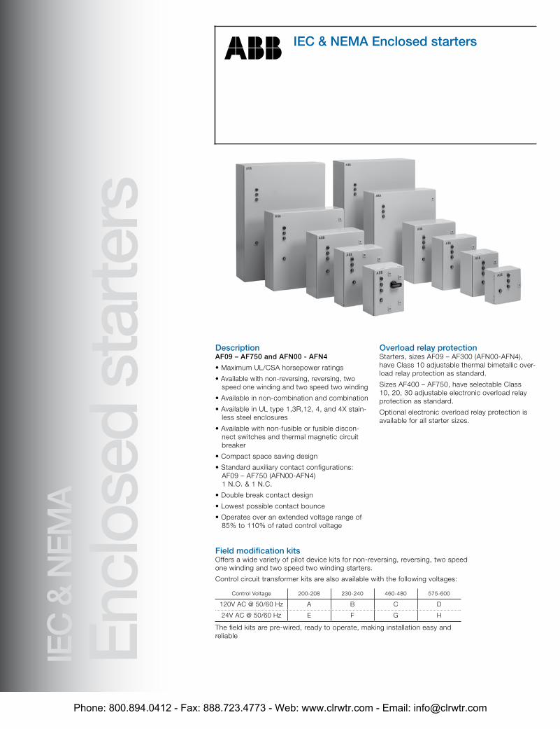
DescriptionAF09 – AF750 and AFN00 - AFN4
• Maximum UL/CSA horsepower ratings
• Available with non-reversing, reversing, two speed one winding and two speed two winding
• Available in non-combination and combination
• Available in UL type 1,3R,12, 4, and 4X stain-less steel enclosures
• Available with non-fusible or fusible discon-nect switches and thermal magnetic circuit breaker
• Compact space saving design
• Standard auxiliary contact configurations: AF09 – AF750 (AFN00-AFN4) 1 N.O. & 1 N.C.
• Double break contact design
• Lowest possible contact bounce
• Operates over an extended voltage range of 85% to 110% of rated control voltage
Overload relay protectionStarters, sizes AF09 – AF300 (AFN00-AFN4), have Class 10 adjustable thermal bimetallic over-load relay protection as standard.
Sizes AF400 – AF750, have selectable Class 10, 20, 30 adjustable electronic overload relay protection as standard.
Optional electronic overload relay protection is available for all starter sizes.
General informationProduct overviewIEC & NEMA Enclosed starters
IEC
& N
EMA
Encl
osed
sta
rters
Field modification kitsOffers a wide variety of pilot device kits for non-reversing, reversing, two speed one winding and two speed two winding starters.
Control circuit transformer kits are also available with the following voltages:
Control Voltage 200-208 230-240 460-480 575-600
120V AC @ 50/60 Hz A B C D
24V AC @ 50/60 Hz E F G H
The field kits are pre-wired, ready to operate, making installation easy and reliable
Phone: 800.894.0412 - Fax: 888.723.4773 - Web: www.clrwtr.com - Email: [email protected]
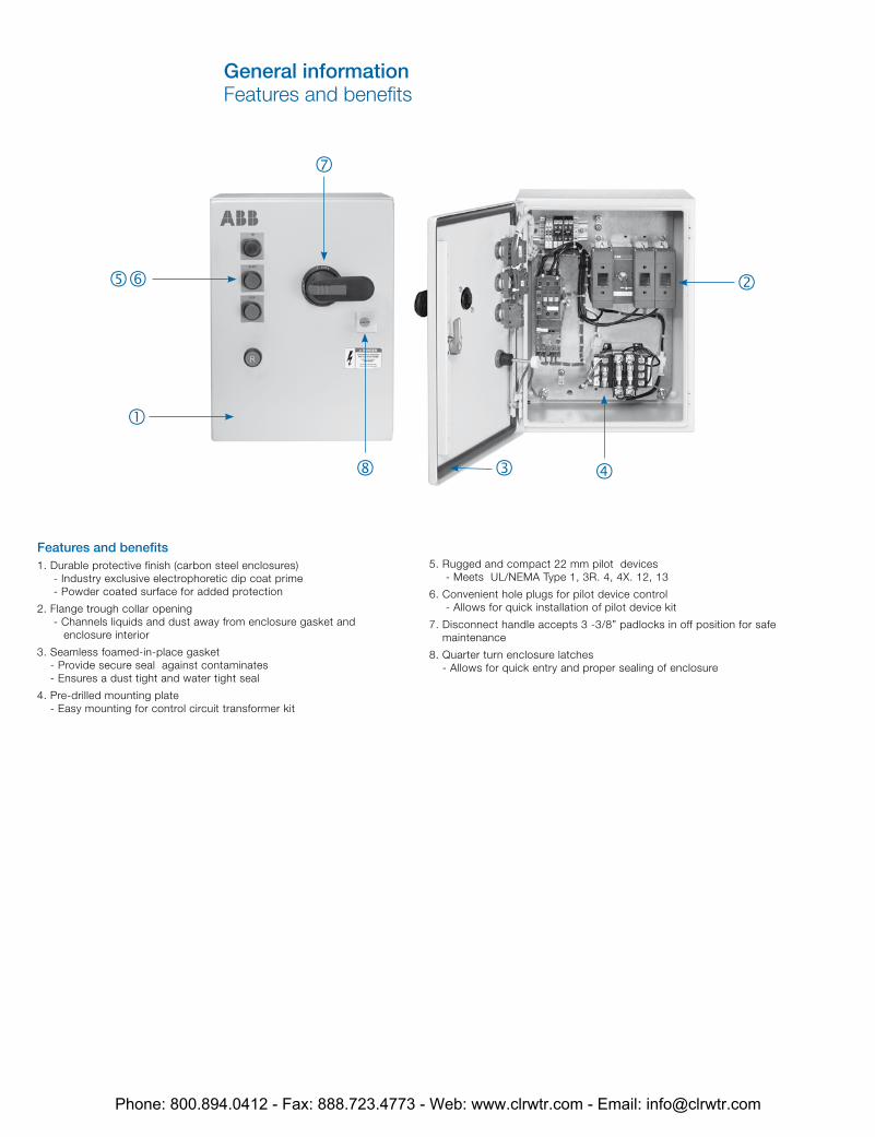
Features and benefits1. Durable protective finish (carbon steel enclosures) - Industry exclusive electrophoretic dip coat prime - Powder coated surface for added protection
2. Flange trough collar opening - Channels liquids and dust away from enclosure gasket and
enclosure interior
3. Seamless foamed-in-place gasket - Provide secure seal against contaminates - Ensures a dust tight and water tight seal
4. Pre-drilled mounting plate - Easy mounting for control circuit transformer kit
5. Rugged and compact 22 mm pilot devices - Meets UL/NEMA Type 1, 3R. 4, 4X. 12, 13
6. Convenient hole plugs for pilot device control - Allows for quick installation of pilot device kit
7. Disconnect handle accepts 3 -3/8” padlocks in off position for safe maintenance
8. Quarter turn enclosure latches - Allows for quick entry and proper sealing of enclosure
7
56
8 3 4
2
1
General informationFeatures and benefits
Phone: 800.894.0412 - Fax: 888.723.4773 - Web: www.clrwtr.com - Email: [email protected]
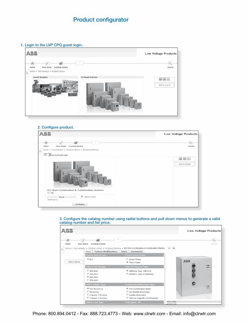
3. Configure the catalog number using radial buttons and pull down menus to generate a valid catalog number and list price.
1. Login to the LVP CPQ guest login.
2. Configure product.
Product configurator
Phone: 800.894.0412 - Fax: 888.723.4773 - Web: www.clrwtr.com - Email: [email protected]
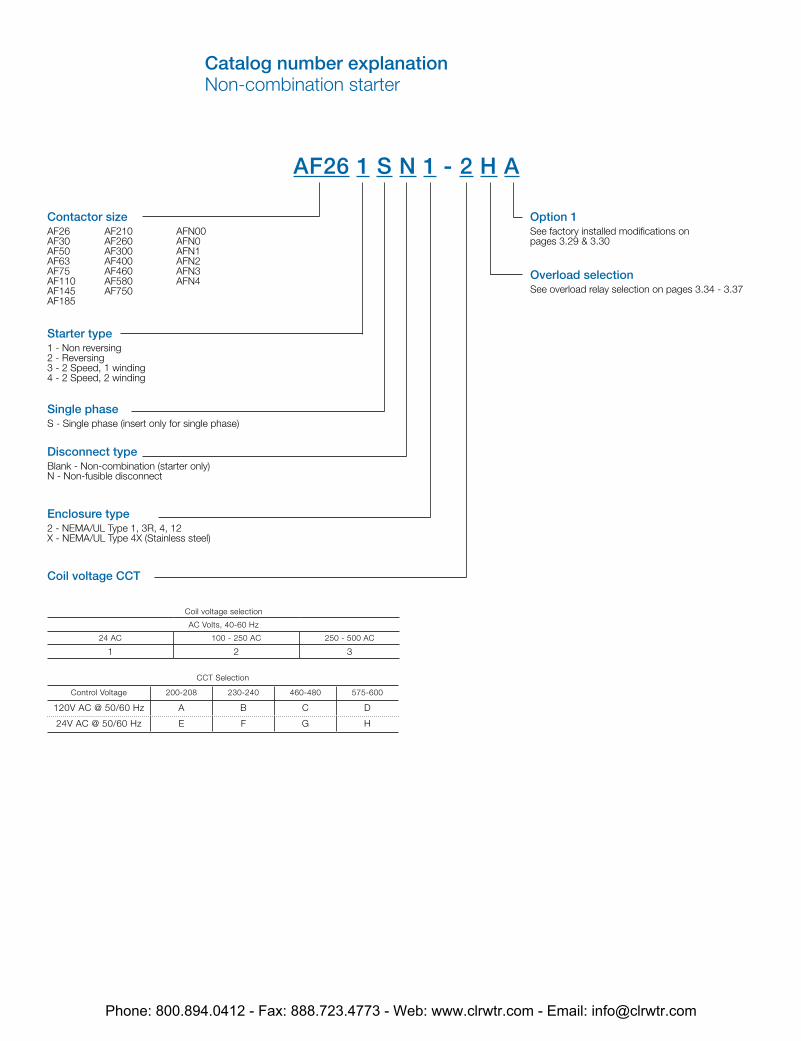
AF26 1 S N 1 - 2 H A
Contactor sizeAF26 AF210 AFN00AF30 AF260 AFN0AF50 AF300 AFN1AF63 AF400 AFN2AF75 AF460 AFN3AF110 AF580 AFN4AF145 AF750AF185
Starter type1 - Non reversing2 - Reversing3 - 2 Speed, 1 winding4 - 2 Speed, 2 winding
Single phaseS - Single phase (insert only for single phase)
Disconnect typeBlank - Non-combination (starter only)N - Non-fusible disconnect
Enclosure type2 - NEMA/UL Type 1, 3R, 4, 12X - NEMA/UL Type 4X (Stainless steel)
Coil voltage CCT
Coil voltage selection
AC Volts, 40-60 Hz
24 AC 100 - 250 AC 250 - 500 AC
1 2 3
CCT Selection
Control Voltage 200-208 230-240 460-480 575-600
120V AC @ 50/60 Hz A B C D
24V AC @ 50/60 Hz E F G H
Overload selectionSee overload relay selection on pages 3.34 - 3.37
Option 1See factory installed modifications on pages 3.29 & 3.30
Catalog number explanationNon-combination starter
Phone: 800.894.0412 - Fax: 888.723.4773 - Web: www.clrwtr.com - Email: [email protected]
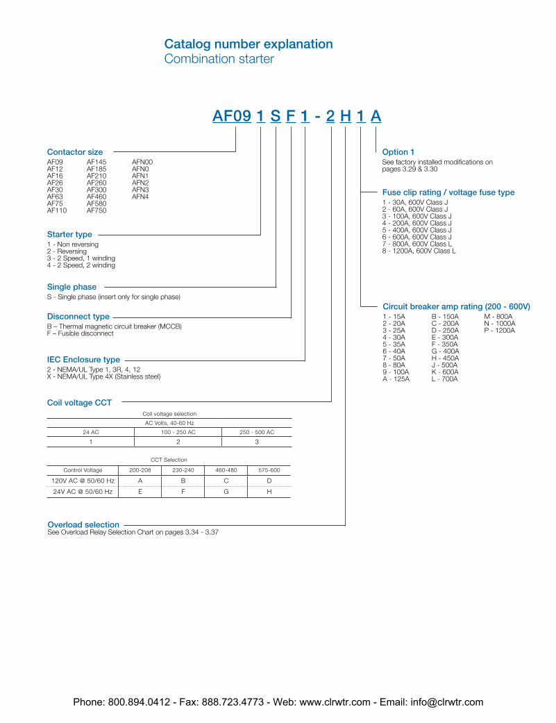
AF09 1 S F 1 - 2 H 1 A
Contactor sizeAF09 AF145 AFN00AF12 AF185 AFN0AF16 AF210 AFN1AF26 AF260 AFN2AF30 AF300 AFN3AF63 AF460 AFN4AF75 AF580AF110 AF750
Starter type1 - Non reversing2 - Reversing3 - 2 Speed, 1 winding4 - 2 Speed, 2 winding
Single phaseS - Single phase (insert only for single phase)
Disconnect typeB – Thermal magnetic circuit breaker (MCCB)F – Fusible disconnect
IEC Enclosure type2 - NEMA/UL Type 1, 3R, 4, 12X - NEMA/UL Type 4X (Stainless steel)
Coil voltage CCTCoil voltage selection
AC Volts, 40-60 Hz
24 AC 100 - 250 AC 250 - 500 AC
1 2 3
CCT Selection
Control Voltage 200-208 230-240 460-480 575-600
120V AC @ 50/60 Hz A B C D
24V AC @ 50/60 Hz E F G H
Fuse clip rating / voltage fuse type1 - 30A, 600V Class J2 - 60A, 600V Class J3 - 100A, 600V Class J4 - 200A, 600V Class J5 - 400A, 600V Class J 6 - 600A, 600V Class J7 - 800A, 600V Class L8 - 1200A, 600V Class L
Option 1See factory installed modifications on pages 3.29 & 3.30
Circuit breaker amp rating (200 - 600V)1 - 15A B - 150A M - 800A2 - 20A C - 200A N - 1000A3 - 25A D - 250A P - 1200A4 - 30A E - 300A5 - 35A F - 350A6 - 40A G - 400A7 - 50A H - 450A8 - 80A J - 500A9 - 100A K - 600AA - 125A L - 700A
Overload selectionSee Overload Relay Selection Chart on pages 3.34 - 3.37
Catalog number explanationCombination starter
Phone: 800.894.0412 - Fax: 888.723.4773 - Web: www.clrwtr.com - Email: [email protected]
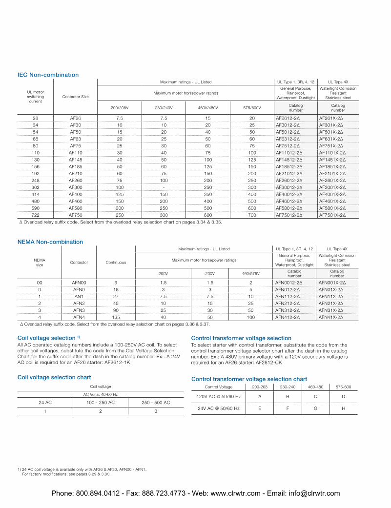
IEC Non-combination
UL motor switching current
Contactor Size
Maximum ratings - UL Listed UL Type 1, 3R, 4, 12 UL Type 4X
Maximum motor horsepower ratingsGeneral Purpose,
Rainproof, Waterproof, Dusttight
Watertight Corrosion Resistant
Stainless steel
200/208V 230/240V 460V/480V 575/600VCatalognumber
Catalognumber
28 AF26 7.5 7.5 15 20 AF2612-2∆ AF261X-2∆
34 AF30 10 10 20 25 AF3012-2∆ AF301X-2∆
54 AF50 15 20 40 50 AF5012-2∆ AF501X-2∆
68 AF63 20 25 50 60 AF6312-2∆ AF631X-2∆
80 AF75 25 30 60 75 AF7512-2∆ AF751X-2∆
110 AF110 30 40 75 100 AF11012-2∆ AF1101X-2∆
130 AF145 40 50 100 125 AF14512-2∆ AF1451X-2∆
156 AF185 50 60 125 150 AF18512-2∆ AF1851X-2∆
192 AF210 60 75 150 200 AF21012-2∆ AF2101X-2∆
248 AF260 75 100 200 250 AF26012-2∆ AF2601X-2∆
302 AF300 100 - 250 300 AF30012-2∆ AF3001X-2∆
414 AF400 125 150 350 400 AF40012-2∆ AF4001X-2∆
480 AF460 150 200 400 500 AF46012-2∆ AF4601X-2∆
590 AF580 200 250 500 600 AF58012-2∆ AF5801X-2∆
722 AF750 250 300 600 700 AF75012-2∆ AF7501X-2∆
∆ Overload relay suffix code. Select from the overload relay selection chart on pages 3.34 & 3.35.
Coil voltage selection 1) All AC operated catalog numbers include a 100-250V AC coil. To select other coil voltages, substitute the code from the Coil Voltage Selection Chart for the suffix code after the dash in the catalog number. Ex.: A 24V AC coil is required for an AF26 starter: AF2612-1K
Control transformer voltage selection To select starter with control transformer, substitute the code from the control transformer voltage selector chart after the dash in the catalog number. Ex.: A 480V primary voltage with a 120V secondary voltage is required for an AF26 starter: AF2612-CK
Coil voltage selection chart
Coil voltage
AC Volts, 40-60 Hz
24 AC 100 - 250 AC 250 - 500 AC
1 2 3
1) 24 AC coil voltage is available only with AF26 & AF30, AFN00 - AFN1, For factory modifications, see pages 3.29 & 3.30.
Control transformer voltage selection chartControl Voltage 200-208 230-240 460-480 575-600
120V AC @ 50/60 Hz A B C D
24V AC @ 50/60 Hz E F G H
NEMA Non-combination
NEMAsize
Contactor Continuous
Maximum ratings - UL Listed UL Type 1, 3R, 4, 12 UL Type 4X
Maximum motor horsepower ratingsGeneral Purpose,
Rainproof, Waterproof, Dusttight
Watertight Corrosion Resistant
Stainless steel
200V 230V 460/575VCatalognumber
Catalognumber
00 AFN00 9 1.5 1.5 2 AFN0012-2∆ AFN001X-2∆
0 AFN0 18 3 3 5 AFN012-2∆ AFN01X-2∆
1 AN1 27 7.5 7.5 10 AFN112-2∆ AFN11X-2∆
2 AFN2 45 10 15 25 AFN212-2∆ AFN21X-2∆
3 AFN3 90 25 30 50 AFN312-2∆ AFN31X-2∆
4 AFN4 135 40 50 100 AFN412-2∆ AFN41X-2∆
∆ Overload relay suffix code. Select from the overload relay selection chart on pages 3.36 & 3.37.
Phone: 800.894.0412 - Fax: 888.723.4773 - Web: www.clrwtr.com - Email: [email protected]
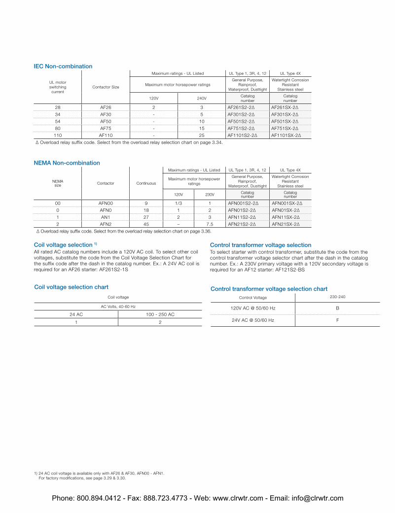
IEC Non-combination
UL motor switching current
Contactor Size
Maximum ratings - UL Listed UL Type 1, 3R, 4, 12 UL Type 4X
Maximum motor horsepower ratingsGeneral Purpose,
Rainproof, Waterproof, Dusttight
Watertight Corrosion Resistant
Stainless steel
120V 240VCatalognumber
Catalognumber
28 AF26 2 3 AF261S2-2∆ AF261SX-2∆
34 AF30 - 5 AF301S2-2∆ AF301SX-2∆
54 AF50 - 10 AF501S2-2∆ AF501SX-2∆
80 AF75 - 15 AF751S2-2∆ AF751SX-2∆
110 AF110 - 25 AF1101S2-2∆ AF1101SX-2∆
∆ Overload relay suffix code. Select from the overload relay selection chart on page 3.34.
Coil voltage selection 1) All rated AC catalog numbers include a 120V AC coil. To select other coil voltages, substitute the code from the Coil Voltage Selection Chart for the suffix code after the dash in the catalog number. Ex.: A 24V AC coil is required for an AF26 starter: AF261S2-1S
Control transformer voltage selection To select starter with control transformer, substitute the code from the control transformer voltage selector chart after the dash in the catalog number. Ex.: A 230V primary voltage with a 120V secondary voltage is required for an AF12 starter: AF121S2-BS
Coil voltage selection chart
Coil voltage
AC Volts, 40-60 Hz
24 AC 100 - 250 AC
1 2
Control transformer voltage selection chartControl Voltage 230-240
120V AC @ 50/60 Hz B
24V AC @ 50/60 Hz F
1) 24 AC coil voltage is available only with AF26 & AF30, AFN00 - AFN1. For factory modifications, see page 3.29 & 3.30.
NEMA Non-combination
NEMAsize Contactor Continuous
Maximum ratings - UL Listed UL Type 1, 3R, 4, 12 UL Type 4X
Maximum motor horsepower ratings
General Purpose, Rainproof,
Waterproof, Dusttight
Watertight Corrosion Resistant
Stainless steel
120V 230V Catalognumber
Catalognumber
00 AFN00 9 1/3 1 AFN001S2-2∆ AFN001SX-2∆
0 AFN0 18 1 2 AFN01S2-2∆ AFN01SX-2∆
1 AN1 27 2 3 AFN11S2-2∆ AFN11SX-2∆
2 AFN2 45 – 7.5 AFN21S2-2∆ AFN21SX-2∆
∆ Overload relay suffix code. Select from the overload relay selection chart on page 3.36.
Phone: 800.894.0412 - Fax: 888.723.4773 - Web: www.clrwtr.com - Email: [email protected]
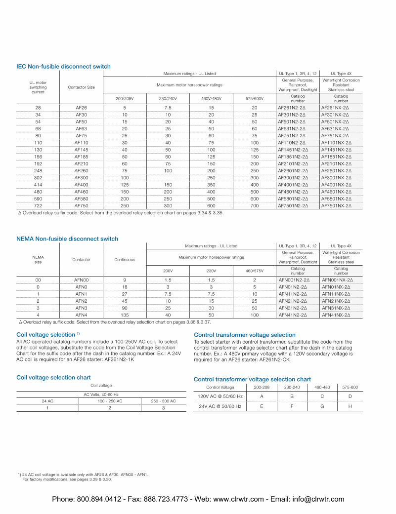
IEC Non-fusible disconnect switch
UL motor switching current
Contactor Size
Maximum ratings - UL Listed UL Type 1, 3R, 4, 12 UL Type 4X
Maximum motor horsepower ratingsGeneral Purpose,
Rainproof, Waterproof, Dusttight
Watertight Corrosion Resistant
Stainless steel
200/208V 230/240V 460V/480V 575/600VCatalognumber
Catalognumber
28 AF26 5 7.5 15 20 AF261N2-2∆ AF261NX-2∆
34 AF30 10 10 20 25 AF301N2-2∆ AF301NX-2∆
54 AF50 15 20 40 50 AF501N2-2∆ AF501NX-2∆
68 AF63 20 25 50 60 AF631N2-2∆ AF631NX-2∆
80 AF75 25 30 60 75 AF751N2-2∆ AF751NX-2∆
110 AF110 30 40 75 100 AF110N2-2∆ AF1101NX-2∆
130 AF145 40 50 100 125 AF1451N2-2∆ AF1451NX-2∆
156 AF185 50 60 125 150 AF1851N2-2∆ AF1851NX-2∆
192 AF210 60 75 150 200 AF2101N2-2∆ AF2101NX-2∆
248 AF260 75 100 200 250 AF2601N2-2∆ AF2601NX-2∆
302 AF300 100 - 250 300 AF3001N2-2∆ AF3001NX-2∆
414 AF400 125 150 350 400 AF4001N2-2∆ AF4001NX-2∆
480 AF460 150 200 400 500 AF4601N2-2∆ AF4601NX-2∆
590 AF580 200 250 500 600 AF5801N2-2∆ AF5801NX-2∆
722 AF750 250 300 600 700 AF7501N2-2∆ AF7501NX-2∆
∆ Overload relay suffix code. Select from the overload relay selection chart on pages 3.34 & 3.35.
Coil voltage selection 1) All AC operated catalog numbers include a 100-250V AC coil. To select other coil voltages, substitute the code from the Coil Voltage Selection Chart for the suffix code after the dash in the catalog number. Ex.: A 24V AC coil is required for an AF26 starter: AF261N2-1K
Control transformer voltage selection To select starter with control transformer, substitute the code from the control transformer voltage selector chart after the dash in the catalog number. Ex.: A 480V primary voltage with a 120V secondary voltage is required for an AF26 starter: AF261N2-CK
Coil voltage selection chartCoil voltage
AC Volts, 40-60 Hz
24 AC 100 - 250 AC 250 - 500 AC
1 2 3
Control transformer voltage selection chartControl Voltage 200-208 230-240 460-480 575-600
120V AC @ 50/60 Hz A B C D
24V AC @ 50/60 Hz E F G H
1) 24 AC coil voltage is available only with AF26 & AF30, AFN00 - AFN1. For factory modifications, see pages 3.29 & 3.30.
NEMA Non-fusible disconnect switch
NEMAsize
Contactor Continuous
Maximum ratings - UL Listed UL Type 1, 3R, 4, 12 UL Type 4X
Maximum motor horsepower ratingsGeneral Purpose,
Rainproof, Waterproof, Dusttight
Watertight Corrosion Resistant
Stainless steel
200V 230V 460/575VCatalognumber
Catalognumber
00 AFN00 9 1.5 1.5 2 AFN001N2-2∆ AFN001NX-2∆
0 AFN0 18 3 3 5 AFN01N2-2∆ AFN01NX-2∆
1 AFN1 27 7.5 7.5 10 AFN11N2-2∆ AFN11NX-2∆
2 AFN2 45 10 15 25 AFN21N2-2∆ AFN21NX-2∆
3 AFN3 90 25 30 50 AFN31N2-2∆ AFN31NX-2∆
4 AFN4 135 40 50 100 AFN41N2-2∆ AFN41NX-2∆
∆ Overload relay suffix code. Select from the overload relay selection chart on pages 3.36 & 3.37.
Phone: 800.894.0412 - Fax: 888.723.4773 - Web: www.clrwtr.com - Email: [email protected]
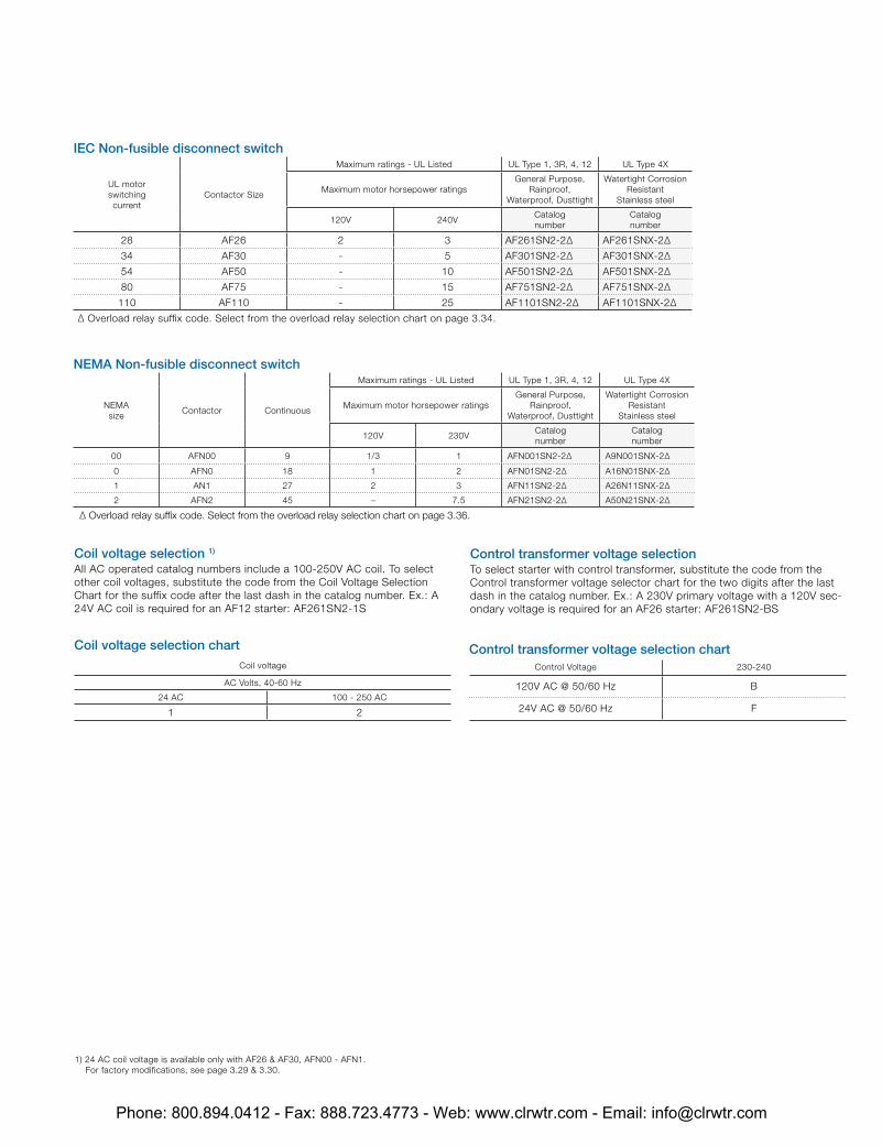
IEC Non-fusible disconnect switch
UL motor switching current
Contactor Size
Maximum ratings - UL Listed UL Type 1, 3R, 4, 12 UL Type 4X
Maximum motor horsepower ratingsGeneral Purpose,
Rainproof, Waterproof, Dusttight
Watertight Corrosion Resistant
Stainless steel
120V 240VCatalognumber
Catalognumber
28 AF26 2 3 AF261SN2-2∆ AF261SNX-2∆
34 AF30 - 5 AF301SN2-2∆ AF301SNX-2∆
54 AF50 - 10 AF501SN2-2∆ AF501SNX-2∆
80 AF75 - 15 AF751SN2-2∆ AF751SNX-2∆
110 AF110 - 25 AF1101SN2-2∆ AF1101SNX-2∆
∆ Overload relay suffix code. Select from the overload relay selection chart on page 3.34.
Coil voltage selection 1) All AC operated catalog numbers include a 100-250V AC coil. To select other coil voltages, substitute the code from the Coil Voltage Selection Chart for the suffix code after the last dash in the catalog number. Ex.: A 24V AC coil is required for an AF12 starter: AF261SN2-1S
Control transformer voltage selection To select starter with control transformer, substitute the code from the Control transformer voltage selector chart for the two digits after the last dash in the catalog number. Ex.: A 230V primary voltage with a 120V sec-ondary voltage is required for an AF26 starter: AF261SN2-BS
Coil voltage selection chartCoil voltage
AC Volts, 40-60 Hz
24 AC 100 - 250 AC
1 2
Control transformer voltage selection chartControl Voltage 230-240
120V AC @ 50/60 Hz B
24V AC @ 50/60 Hz F
1) 24 AC coil voltage is available only with AF26 & AF30, AFN00 - AFN1. For factory modifications, see page 3.29 & 3.30.
NEMA Non-fusible disconnect switch
NEMAsize
Contactor Continuous
Maximum ratings - UL Listed UL Type 1, 3R, 4, 12 UL Type 4X
Maximum motor horsepower ratingsGeneral Purpose,
Rainproof, Waterproof, Dusttight
Watertight Corrosion Resistant
Stainless steel
120V 230VCatalognumber
Catalognumber
00 AFN00 9 1/3 1 AFN001SN2-2∆ A9N001SNX-2∆
0 AFN0 18 1 2 AFN01SN2-2∆ A16N01SNX-2∆
1 AN1 27 2 3 AFN11SN2-2∆ A26N11SNX-2∆
2 AFN2 45 – 7.5 AFN21SN2-2∆ A50N21SNX-2∆
∆ Overload relay suffix code. Select from the overload relay selection chart on page 3.36.
Phone: 800.894.0412 - Fax: 888.723.4773 - Web: www.clrwtr.com - Email: [email protected]
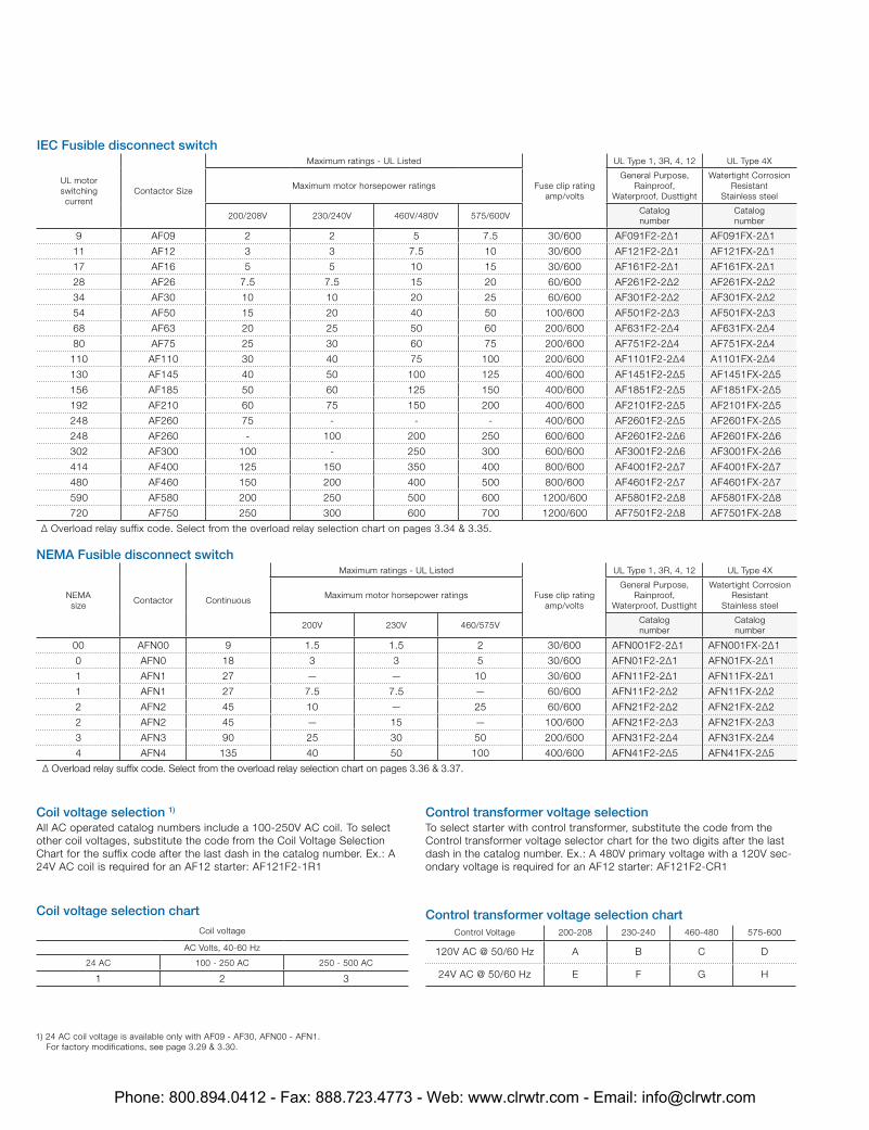
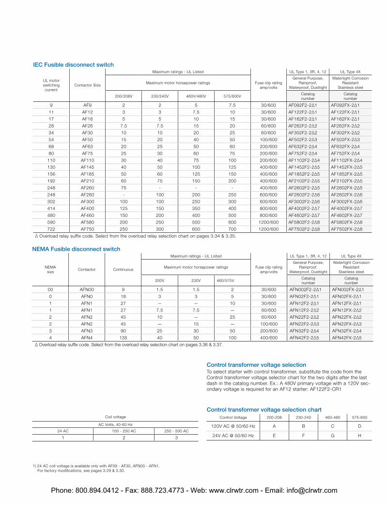
IEC Fusible disconnect switch
UL motor switching current
Contactor Size
Maximum ratings - UL Listed
Fuse clip rating amp/volts
UL Type 1, 3R, 4, 12 UL Type 4X
Maximum motor horsepower ratingsGeneral Purpose,
Rainproof, Waterproof, Dusttight
Watertight Corrosion Resistant
Stainless steel
200/208V 230/240V 460V/480V 575/600VCatalognumber
Catalognumber
9 AF09 2 2 5 7.5 30/600 AF091F2-2∆1 AF091FX-2∆1
11 AF12 3 3 7.5 10 30/600 AF121F2-2∆1 AF121FX-2∆1
17 AF16 5 5 10 15 30/600 AF161F2-2∆1 AF161FX-2∆1
28 AF26 7.5 7.5 15 20 60/600 AF261F2-2∆2 AF261FX-2∆2
34 AF30 10 10 20 25 60/600 AF301F2-2∆2 AF301FX-2∆2
54 AF50 15 20 40 50 100/600 AF501F2-2∆3 AF501FX-2∆3
68 AF63 20 25 50 60 200/600 AF631F2-2∆4 AF631FX-2∆4
80 AF75 25 30 60 75 200/600 AF751F2-2∆4 AF751FX-2∆4
110 AF110 30 40 75 100 200/600 AF1101F2-2∆4 A1101FX-2∆4
130 AF145 40 50 100 125 400/600 AF1451F2-2∆5 AF1451FX-2∆5
156 AF185 50 60 125 150 400/600 AF1851F2-2∆5 AF1851FX-2∆5
192 AF210 60 75 150 200 400/600 AF2101F2-2∆5 AF2101FX-2∆5
248 AF260 75 - - - 400/600 AF2601F2-2∆5 AF2601FX-2∆5
248 AF260 - 100 200 250 600/600 AF2601F2-2∆6 AF2601FX-2∆6
302 AF300 100 - 250 300 600/600 AF3001F2-2∆6 AF3001FX-2∆6
414 AF400 125 150 350 400 800/600 AF4001F2-2∆7 AF4001FX-2∆7
480 AF460 150 200 400 500 800/600 AF4601F2-2∆7 AF4601FX-2∆7
590 AF580 200 250 500 600 1200/600 AF5801F2-2∆8 AF5801FX-2∆8
720 AF750 250 300 600 700 1200/600 AF7501F2-2∆8 AF7501FX-2∆8
∆ Overload relay suffix code. Select from the overload relay selection chart on pages 3.34 & 3.35.
Coil voltage selection 1) All AC operated catalog numbers include a 100-250V AC coil. To select other coil voltages, substitute the code from the Coil Voltage Selection Chart for the suffix code after the last dash in the catalog number. Ex.: A 24V AC coil is required for an AF12 starter: AF121F2-1R1
Coil voltage selection chartCoil voltage
AC Volts, 40-60 Hz
24 AC 100 - 250 AC 250 - 500 AC
1 2 3
Control transformer voltage selection chartControl Voltage 200-208 230-240 460-480 575-600
120V AC @ 50/60 Hz A B C D
24V AC @ 50/60 Hz E F G H
Control transformer voltage selection To select starter with control transformer, substitute the code from the Control transformer voltage selector chart for the two digits after the last dash in the catalog number. Ex.: A 480V primary voltage with a 120V sec-ondary voltage is required for an AF12 starter: AF121F2-CR1
1) 24 AC coil voltage is available only with AF09 - AF30, AFN00 - AFN1. For factory modifications, see page 3.29 & 3.30.
NEMA Fusible disconnect switch
NEMAsize
Contactor Continuous
Maximum ratings - UL Listed
Fuse clip rating amp/volts
UL Type 1, 3R, 4, 12 UL Type 4X
Maximum motor horsepower ratingsGeneral Purpose,
Rainproof, Waterproof, Dusttight
Watertight Corrosion Resistant
Stainless steel
200V 230V 460/575VCatalognumber
Catalognumber
00 AFN00 9 1.5 1.5 2 30/600 AFN001F2-2∆1 AFN001FX-2∆1
0 AFN0 18 3 3 5 30/600 AFN01F2-2∆1 AFN01FX-2∆1
1 AFN1 27 — — 10 30/600 AFN11F2-2∆1 AFN11FX-2∆1
1 AFN1 27 7.5 7.5 — 60/600 AFN11F2-2∆2 AFN11FX-2∆2
2 AFN2 45 10 — 25 60/600 AFN21F2-2∆2 AFN21FX-2∆2
2 AFN2 45 — 15 — 100/600 AFN21F2-2∆3 AFN21FX-2∆3
3 AFN3 90 25 30 50 200/600 AFN31F2-2∆4 AFN31FX-2∆4
4 AFN4 135 40 50 100 400/600 AFN41F2-2∆5 AFN41FX-2∆5
∆ Overload relay suffix code. Select from the overload relay selection chart on pages 3.36 & 3.37.
Phone: 800.894.0412 - Fax: 888.723.4773 - Web: www.clrwtr.com - Email: [email protected]
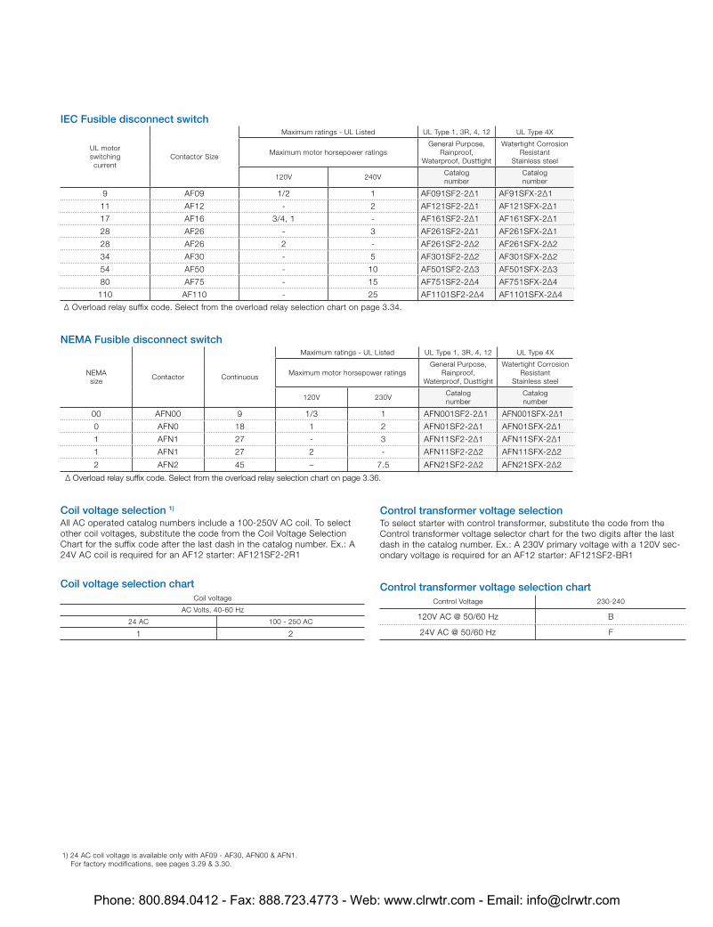
IEC Fusible disconnect switch
UL motor switching current
Contactor Size
Maximum ratings - UL Listed UL Type 1, 3R, 4, 12 UL Type 4X
Maximum motor horsepower ratingsGeneral Purpose,
Rainproof, Waterproof, Dusttight
Watertight Corrosion Resistant
Stainless steel
120V 240VCatalognumber
Catalognumber
9 AF09 1/2 1 AF091SF2-2∆1 AF91SFX-2∆1
11 AF12 - 2 AF121SF2-2∆1 AF121SFX-2∆1
17 AF16 3/4, 1 - AF161SF2-2∆1 AF161SFX-2∆1
28 AF26 - 3 AF261SF2-2∆1 AF261SFX-2∆1
28 AF26 2 - AF261SF2-2∆2 AF261SFX-2∆2
34 AF30 - 5 AF301SF2-2∆2 AF301SFX-2∆2
54 AF50 - 10 AF501SF2-2∆3 AF501SFX-2∆3
80 AF75 - 15 AF751SF2-2∆4 AF751SFX-2∆4
110 AF110 - 25 AF1101SF2-2∆4 AF1101SFX-2∆4
∆ Overload relay suffix code. Select from the overload relay selection chart on page 3.34.
Coil voltage selection 1) All AC operated catalog numbers include a 100-250V AC coil. To select other coil voltages, substitute the code from the Coil Voltage Selection Chart for the suffix code after the last dash in the catalog number. Ex.: A 24V AC coil is required for an AF12 starter: AF121SF2-2R1
Control transformer voltage selection To select starter with control transformer, substitute the code from the Control transformer voltage selector chart for the two digits after the last dash in the catalog number. Ex.: A 230V primary voltage with a 120V sec-ondary voltage is required for an AF12 starter: AF121SF2-BR1
Coil voltage selection chartCoil voltage
AC Volts, 40-60 Hz
24 AC 100 - 250 AC
1 2
Control transformer voltage selection chartControl Voltage 230-240
120V AC @ 50/60 Hz B
24V AC @ 50/60 Hz F
1) 24 AC coil voltage is available only with AF09 - AF30, AFN00 & AFN1. For factory modifications, see pages 3.29 & 3.30.
NEMA Fusible disconnect switch
NEMAsize
Contactor Continuous
Maximum ratings - UL Listed UL Type 1, 3R, 4, 12 UL Type 4X
Maximum motor horsepower ratingsGeneral Purpose,
Rainproof, Waterproof, Dusttight
Watertight Corrosion Resistant
Stainless steel
120V 230VCatalognumber
Catalognumber
00 AFN00 9 1/3 1 AFN001SF2-2∆1 AFN001SFX-2∆1
0 AFN0 18 1 2 AFN01SF2-2∆1 AFN01SFX-2∆1
1 AFN1 27 - 3 AFN11SF2-2∆1 AFN11SFX-2∆1
1 AFN1 27 2 - AFN11SF2-2∆2 AFN11SFX-2∆2
2 AFN2 45 – 7.5 AFN21SF2-2∆2 AFN21SFX-2∆2
∆ Overload relay suffix code. Select from the overload relay selection chart on page 3.36.
Phone: 800.894.0412 - Fax: 888.723.4773 - Web: www.clrwtr.com - Email: [email protected]
UL motor switching current
Contactor Size
Maximum ratings - UL Listed
Circuit Breaker Amp Rating
UL Type 1, 3R, 4, 12 UL Type 4X
Maximum motor horsepower ratingsGeneral Purpose,
Rainproof, Waterproof, Dusttight
Watertight Corrosion Resistant
Stainless steel
200/208V 230/240V 460V/480V 575/600VCatalognumber
Catalognumber
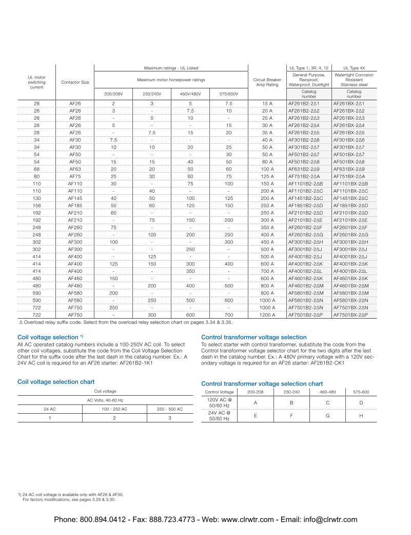
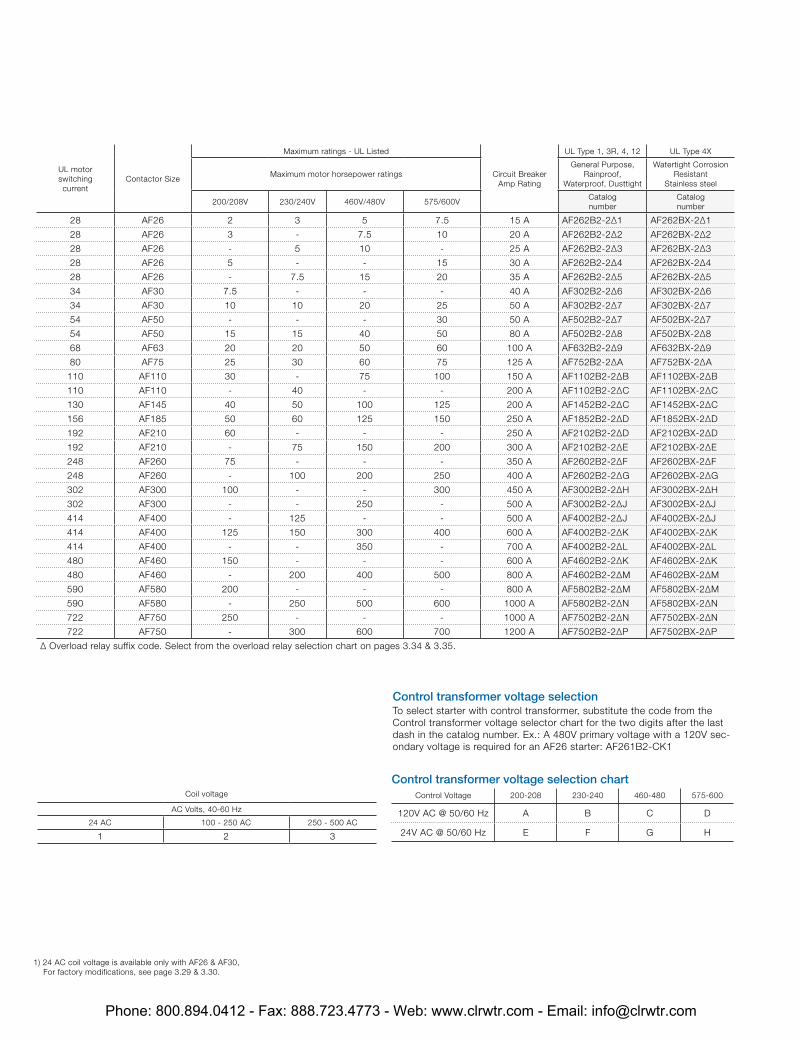
28 AF26 2 3 5 7.5 15 A AF261B2-2∆1 AF261BX-2∆1
28 AF26 3 - 7.5 10 20 A AF261B2-2∆2 AF261BX-2∆2
28 AF26 - 5 10 - 25 A AF261B2-2∆3 AF261BX-2∆3
28 AF26 5 - - 15 30 A AF261B2-2∆4 AF261BX-2∆4
28 AF26 - 7.5 15 20 35 A AF261B2-2∆5 AF261BX-2∆5
34 AF30 7.5 - - - 40 A AF301B2-2∆6 AF301BX-2∆6
34 AF30 10 10 20 25 50 A AF301B2-2∆7 AF301BX-2∆7
54 AF50 - - - 30 50 A AF501B2-2∆7 AF501BX-2∆7
54 AF50 15 15 40 50 80 A AF501B2-2∆8 AF501BX-2∆8
68 AF63 20 20 50 60 100 A AF631B2-2∆9 AF631BX-2∆9
80 AF75 25 30 60 75 125 A AF751B2-2∆A AF751BX-2∆A
110 AF110 30 - 75 100 150 A AF1101B2-2∆B AF1101BX-2∆B
110 AF110 - 40 - - 200 A AF1101B2-2∆C AF1101BX-2∆C
130 AF145 40 50 100 125 200 A AF1451B2-2∆C AF1451BX-2∆C
156 AF185 50 60 125 150 250 A AF1851B2-2∆D AF1851BX-2∆D
192 AF210 60 - - - 250 A AF2101B2-2∆D AF2101BX-2∆D
192 AF210 - 75 150 200 300 A AF2101B2-2∆E AF2101BX-2∆E
248 AF260 75 - - - 350 A AF2601B2-2∆F AF2601BX-2∆F
248 AF260 - 100 200 250 400 A AF2601B2-2∆G AF2601BX-2∆G
302 AF300 100 - - 300 450 A AF3001B2-2∆H AF3001BX-2∆H
302 AF300 - - 250 - 500 A AF3001B2-2∆J AF3001BX-2∆J
414 AF400 - 125 - - 500 A AF4001B2-2∆J AF4001BX-2∆J
414 AF400 125 150 300 400 600 A AF4001B2-2∆K AF4001BX-2∆K
414 AF400 - - 350 - 700 A AF4001B2-2∆L AF4001BX-2∆L
480 AF460 150 - - - 600 A AF4601B2-2∆K AF4601BX-2∆K
480 AF460 - 200 400 500 800 A AF4601B2-2∆M AF4601BX-2∆M
590 AF580 200 - - - 800 A AF5801B2-2∆M AF5801BX-2∆M
590 AF580 - 250 500 600 1000 A AF5801B2-2∆N AF5801BX-2∆N
722 AF750 250 - - - 1000 A AF7501B2-2∆N AF7501BX-2∆N
722 AF750 - 300 600 700 1200 A AF7501B2-2∆P AF7501BX-2∆P
∆ Overload relay suffix code. Select from the overload relay selection chart on pages 3.34 & 3.35.
Coil voltage selection 1) All AC operated catalog numbers include a 100-250V AC coil. To select other coil voltages, substitute the code from the Coil Voltage Selection Chart for the suffix code after the last dash in the catalog number. Ex.: A 24V AC coil is required for an AF26 starter: AF261B2-1K1
Coil voltage selection chartCoil voltage
AC Volts, 40-60 Hz
24 AC 100 - 250 AC 250 - 500 AC
1 2 3
Control transformer voltage selection chartControl Voltage 200-208 230-240 460-480 575-600
120V AC @ 50/60 Hz
A B C D
24V AC @ 50/60 Hz
E F G H
Control transformer voltage selection To select starter with control transformer, substitute the code from the Control transformer voltage selector chart for the two digits after the last dash in the catalog number. Ex.: A 480V primary voltage with a 120V sec-ondary voltage is required for an AF26 starter: AF261B2-CK1
1) 24 AC coil voltage is available only with AF26 & AF30, For factory modifications, see pages 3.29 & 3.30.
Phone: 800.894.0412 - Fax: 888.723.4773 - Web: www.clrwtr.com - Email: [email protected]
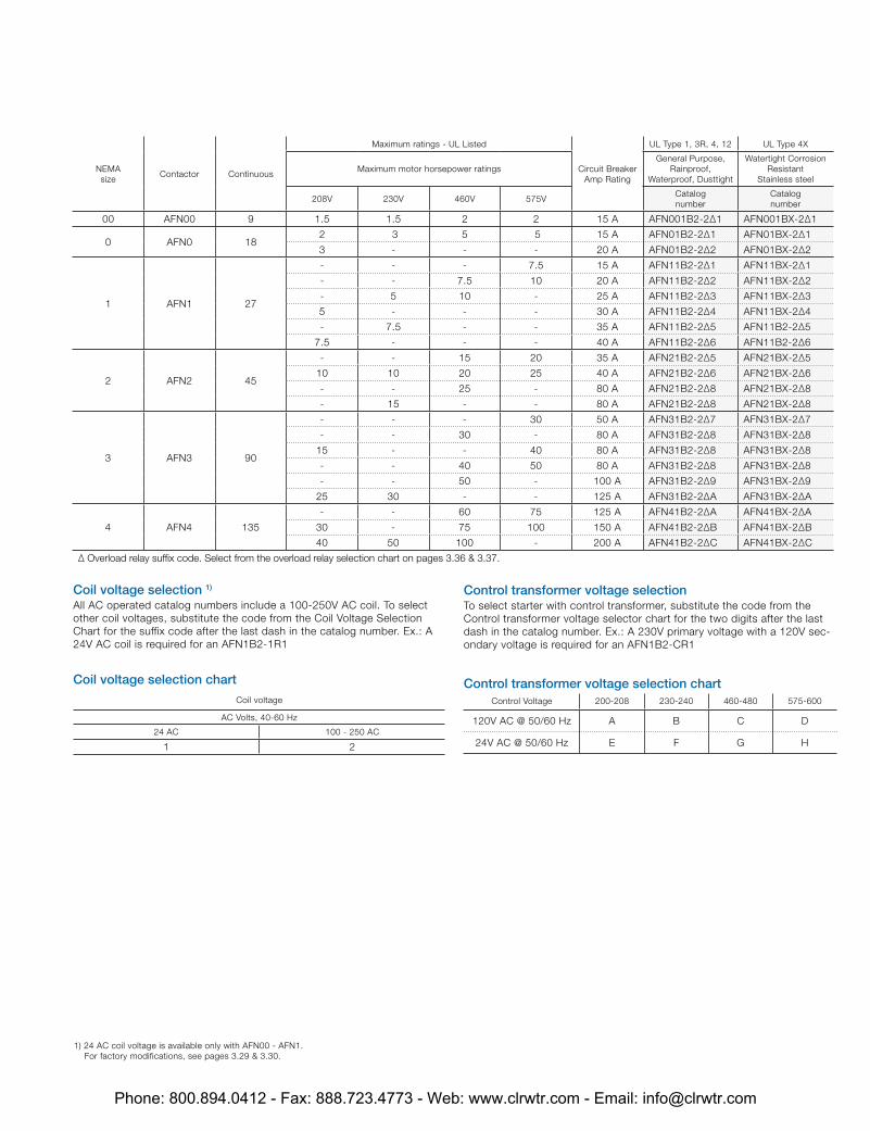
NEMAsize
Contactor Continuous
Maximum ratings - UL Listed
Circuit Breaker Amp Rating
UL Type 1, 3R, 4, 12 UL Type 4X
Maximum motor horsepower ratingsGeneral Purpose,
Rainproof, Waterproof, Dusttight
Watertight Corrosion Resistant
Stainless steel
208V 230V 460V 575VCatalognumber
Catalognumber
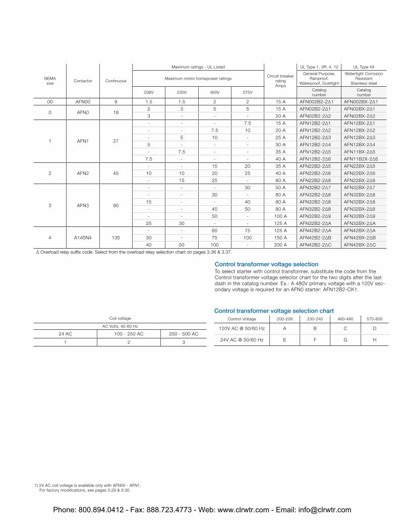
00 AFN00 9 1.5 1.5 2 2 15 A AFN001B2-2∆1 AFN001BX-2∆1
0 AFN0 182 3 5 5 15 A AFN01B2-2∆1 AFN01BX-2∆1
3 - - - 20 A AFN01B2-2∆2 AFN01BX-2∆2
1 AFN1 27
- - - 7.5 15 A AFN11B2-2∆1 AFN11BX-2∆1
- - 7.5 10 20 A AFN11B2-2∆2 AFN11BX-2∆2
- 5 10 - 25 A AFN11B2-2∆3 AFN11BX-2∆3
5 - - - 30 A AFN11B2-2∆4 AFN11BX-2∆4
- 7.5 - - 35 A AFN11B2-2∆5 AFN11B2-2∆5
7.5 - - - 40 A AFN11B2-2∆6 AFN11B2-2∆6
2 AFN2 45
- - 15 20 35 A AFN21B2-2∆5 AFN21BX-2∆5
10 10 20 25 40 A AFN21B2-2∆6 AFN21BX-2∆6
- - 25 - 80 A AFN21B2-2∆8 AFN21BX-2∆8
- 15 - - 80 A AFN21B2-2∆8 AFN21BX-2∆8
3 AFN3 90
- - - 30 50 A AFN31B2-2∆7 AFN31BX-2∆7
- - 30 - 80 A AFN31B2-2∆8 AFN31BX-2∆8
15 - - 40 80 A AFN31B2-2∆8 AFN31BX-2∆8
- - 40 50 80 A AFN31B2-2∆8 AFN31BX-2∆8
- - 50 - 100 A AFN31B2-2∆9 AFN31BX-2∆9
25 30 - - 125 A AFN31B2-2∆A AFN31BX-2∆A
4 AFN4 135
- - 60 75 125 A AFN41B2-2∆A AFN41BX-2∆A
30 - 75 100 150 A AFN41B2-2∆B AFN41BX-2∆B
40 50 100 - 200 A AFN41B2-2∆C AFN41BX-2∆C
∆ Overload relay suffix code. Select from the overload relay selection chart on pages 3.36 & 3.37.
Coil voltage selection 1) All AC operated catalog numbers include a 100-250V AC coil. To select other coil voltages, substitute the code from the Coil Voltage Selection Chart for the suffix code after the last dash in the catalog number. Ex.: A 24V AC coil is required for an AFN1B2-1R1
Control transformer voltage selection To select starter with control transformer, substitute the code from the Control transformer voltage selector chart for the two digits after the last dash in the catalog number. Ex.: A 230V primary voltage with a 120V sec-ondary voltage is required for an AFN1B2-CR1
Coil voltage selection chart
Coil voltage
AC Volts, 40-60 Hz
24 AC 100 - 250 AC
1 2
1) 24 AC coil voltage is available only with AFN00 - AFN1. For factory modifications, see pages 3.29 & 3.30.
Control transformer voltage selection chartControl Voltage 200-208 230-240 460-480 575-600
120V AC @ 50/60 Hz A B C D
24V AC @ 50/60 Hz E F G H
Phone: 800.894.0412 - Fax: 888.723.4773 - Web: www.clrwtr.com - Email: [email protected]
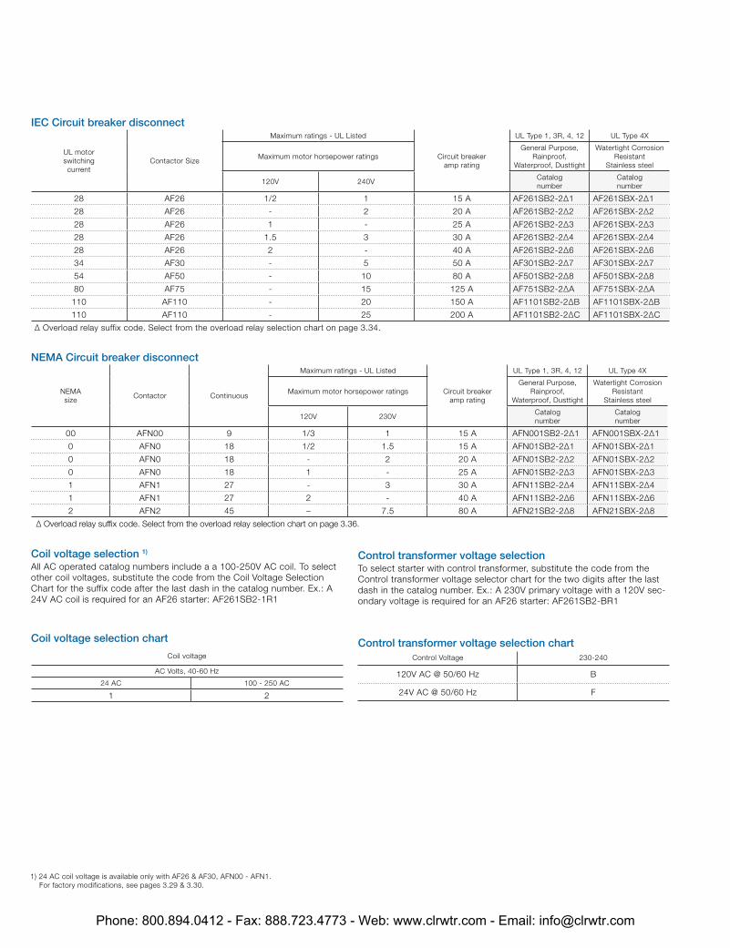
IEC Circuit breaker disconnect
UL motor switching current
Contactor Size
Maximum ratings - UL Listed
Circuit breakeramp rating
UL Type 1, 3R, 4, 12 UL Type 4X
Maximum motor horsepower ratingsGeneral Purpose,
Rainproof, Waterproof, Dusttight
Watertight Corrosion Resistant
Stainless steel
120V 240VCatalognumber
Catalognumber
28 AF26 1/2 1 15 A AF261SB2-2∆1 AF261SBX-2∆1
28 AF26 - 2 20 A AF261SB2-2∆2 AF261SBX-2∆2
28 AF26 1 - 25 A AF261SB2-2∆3 AF261SBX-2∆3
28 AF26 1.5 3 30 A AF261SB2-2∆4 AF261SBX-2∆4
28 AF26 2 - 40 A AF261SB2-2∆6 AF261SBX-2∆6
34 AF30 - 5 50 A AF301SB2-2∆7 AF301SBX-2∆7
54 AF50 - 10 80 A AF501SB2-2∆8 AF501SBX-2∆8
80 AF75 - 15 125 A AF751SB2-2∆A AF751SBX-2∆A
110 AF110 - 20 150 A AF1101SB2-2∆B AF1101SBX-2∆B
110 AF110 - 25 200 A AF1101SB2-2∆C AF1101SBX-2∆C
∆ Overload relay suffix code. Select from the overload relay selection chart on page 3.34.
Coil voltage selection 1) All AC operated catalog numbers include a a 100-250V AC coil. To select other coil voltages, substitute the code from the Coil Voltage Selection Chart for the suffix code after the last dash in the catalog number. Ex.: A 24V AC coil is required for an AF26 starter: AF261SB2-1R1
Coil voltage selection chart
Coil voltage
AC Volts, 40-60 Hz
24 AC 100 - 250 AC
1 2
Control transformer voltage selection To select starter with control transformer, substitute the code from the Control transformer voltage selector chart for the two digits after the last dash in the catalog number. Ex.: A 230V primary voltage with a 120V sec-ondary voltage is required for an AF26 starter: AF261SB2-BR1
Control transformer voltage selection chartControl Voltage 230-240
120V AC @ 50/60 Hz B
24V AC @ 50/60 Hz F
1) 24 AC coil voltage is available only with AF26 & AF30, AFN00 - AFN1. For factory modifications, see pages 3.29 & 3.30.
NEMA Circuit breaker disconnect
NEMAsize
Contactor Continuous
Maximum ratings - UL Listed
Circuit breakeramp rating
UL Type 1, 3R, 4, 12 UL Type 4X
Maximum motor horsepower ratingsGeneral Purpose,
Rainproof, Waterproof, Dusttight
Watertight Corrosion Resistant
Stainless steel
120V 230VCatalognumber
Catalognumber
00 AFN00 9 1/3 1 15 A AFN001SB2-2∆1 AFN001SBX-2∆1
0 AFN0 18 1/2 1.5 15 A AFN01SB2-2∆1 AFN01SBX-2∆1
0 AFN0 18 - 2 20 A AFN01SB2-2∆2 AFN01SBX-2∆2
0 AFN0 18 1 - 25 A AFN01SB2-2∆3 AFN01SBX-2∆3
1 AFN1 27 - 3 30 A AFN11SB2-2∆4 AFN11SBX-2∆4
1 AFN1 27 2 - 40 A AFN11SB2-2∆6 AFN11SBX-2∆6
2 AFN2 45 – 7.5 80 A AFN21SB2-2∆8 AFN21SBX-2∆8
∆ Overload relay suffix code. Select from the overload relay selection chart on page 3.36.
Phone: 800.894.0412 - Fax: 888.723.4773 - Web: www.clrwtr.com - Email: [email protected]

IEC Non-combination
UL motor switching current
Contactor Size
Maximum ratings - UL Listed UL Type 1, 3R, 4, 12 UL Type 4X
Maximum motor horsepower ratingsGeneral Purpose,
Rainproof, Waterproof, Dusttight
Watertight Corrosion Resistant
Stainless steel
200/208V 230/240V 460V/480V 575/600VCatalognumber
Catalognumber
28 AF26 7.5 7.5 15 20 AF2622-2∆ AF262X-2∆
34 AF30 10 10 20 25 AF3022-2∆ AF302X-2∆
54 AF50 15 20 40 50 AF5022-2∆ AF502X-2∆
68 AF63 20 25 50 60 AF6322-2∆ AF632X-2∆
80 AF75 25 30 60 75 AF7522-2∆ AF752X-2∆
110 AF110 30 40 75 100 AF11022-2∆ AF1102X-2∆
130 AF145 40 50 100 125 AF14522-2∆ AF1452X-2∆
156 AF185 50 60 125 150 AF18522-2∆ AF1852X-2∆
192 AF210 60 75 150 200 AF21022-2∆ AF2102X-2∆
248 AF260 75 100 200 250 AF26022-2∆ AF2602X-2∆
302 AF300 100 - 250 300 AF30022-2∆ AF3002X-2∆
414 AF400 125 150 350 400 AF40022-2∆ AF4002X-2∆
480 AF460 150 200 400 500 AF46022-2∆ AF4602X-2∆
590 AF580 200 250 500 600 AF58022-2∆ AF5802X-2∆
720 AF750 250 300 600 700 AF75022-2∆ AF7502X-2∆
∆ Overload relay suffix code. Select from the overload relay selection chart on pages 3.34 & 3.35.
Coil voltage selection 1) All AC operated catalog numbers include a 100-250V AC coil. To select other coil voltages, substitute the code from the Coil Voltage Selection Chart for the suffix code after the last dash in the catalog number. Ex.: A 24V AC coil is required for an AF26 starter: AF2622-1K
Coil voltage selection chart
Coil voltage
AC Volts, 40-60 Hz
24 AC 100 - 250 AC 250 - 500 AC
1 2 3
Control transformer voltage selection chartControl Voltage 200-208 230-240 460-480 575-600
120V AC @ 50/60 Hz A B C D
24V AC @ 50/60 Hz E F G H
Control transformer voltage selection To select starter with control transformer, substitute the code from the Control transformer voltage selector chart for the two digits after the last dash in the catalog number. Ex.: A 480V primary voltage with a 120V sec-ondary voltage is required for an AF26 starter: AF2622-CK
1) 24 AC coil voltage is available only with AF26 & AF30, AFN00 - AFN1. For factory modifications, see pages 3.29 & 3.30.
NEMA Non-combination
NEMAsize
Contactor Continuous
Maximum ratings - UL Listed UL Type 1, 3R, 4, 12 UL Type 4X
Maximum motor horsepower ratingsGeneral Purpose,
Rainproof, Waterproof, Dusttight
Watertight Corrosion Resistant
Stainless steel
200V 230V 460/575VCatalognumber
Catalognumber
00 AFN00 9 1.5 1.5 2 AFN0022-2∆ AFN002X-2∆
0 AFN0 18 3 3 5 AFN022-2∆ AFN02X-2∆
1 AN1 27 7.5 7.5 10 AFN122-2∆ AFN12X-2∆
2 AFN2 45 10 15 25 AFN222-2∆ AFN22X-2∆
3 AFN3 90 25 30 50 AFN322-2∆ AFN32X-2∆
4 AFN4 135 40 50 100 AFN422-2∆ AFN42X-2∆
∆ Overload relay suffix code. Select from the overload relay selection chart on pages 3.36 & 3.37.
Phone: 800.894.0412 - Fax: 888.723.4773 - Web: www.clrwtr.com - Email: [email protected]

IEC Non-combination
UL motor switching current
Contactor Size
Maximum ratings - UL Listed UL Type 1, 3R, 4, 12 UL Type 4X
Maximum motor horsepower ratingsGeneral Purpose,
Rainproof, Waterproof, Dusttight
Watertight Corrosion Resistant
Stainless steel
200/208V 230/240V 460V/480V 575/600VCatalognumber
Catalognumber
28 AF26 7.5 7.5 15 20 AF262N2-2∆ AF262NX-2∆
24 AF30 10 10 20 25 AF302N2-2∆ AF302NX-2∆
54 AF50 15 20 40 50 AF502N2-2∆ AF502NX-2∆
68 AF63 20 25 50 60 AF632N2-2∆ AF632NX-2∆
80 AF75 25 30 60 75 AF752N2-2∆ AF752NX-2∆
110 AF110 30 40 75 100 AF110N2-2∆ AF1102NX-2∆
130 AF145 40 50 100 125 AF1452N2-2∆ AF1452NX-2∆
156 AF185 50 60 125 150 AF1852N2-2∆ AF1852NX-2∆
192 AF210 60 75 150 200 AF2102N2-2∆ AF2102NX-2∆
248 AF260 75 100 200 250 AF2602N2-2∆ AF2602NX-2∆
302 AF300 100 - 250 300 AF3002N2-2∆ AF3002NX-2∆
414 AF400 125 150 350 400 AF4002N2-2∆ AF4002NX-2∆
480 AF460 150 200 400 500 AF4602N2-2∆ AF4602NX-2∆
590 AF580 200 250 500 600 AF5802N2-2∆ AF5802NX-2∆
722 AF750 250 300 600 700 AF7502N2-2∆ AF7502NX-2∆
∆ Overload relay suffix code. Select from the overload relay selection chart on pages 3.34 & 3.35.
Coil voltage selection 1) All AC operated catalog numbers include a 100-250V AC coil. To select other coil voltages, substitute the code from the Coil Voltage Selection Chart for the suffix code after the last dash in the catalog number. Ex.: A 24V AC coil is required for an AF26 starter: AF262N2-1K
Coil voltage selection chartCoil voltage
AC Volts, 40-60 Hz
24 AC 100 - 250 AC 250 - 500 AC
1 2 3
Control transformer voltage selection chartControl Voltage 200-208 230-240 460-480 575-600
120V AC @ 50/60 Hz A B C D
24V AC @ 50/60 Hz E F G H
Control transformer voltage selection To select starter with control transformer, substitute the code from the Control transformer voltage selector chart for the two digits after the last dash in the catalog number. Ex.: A 480V primary voltage with a 120V sec-ondary voltage is required for an AF26 starter: AF262N2-CK
1) 24 AC coil voltage is available only with AF26 & AF30, AFN00 - AFN1. For factory modifications, see pages 3.29 & 3.30.
NEMA Non-combination
NEMAsize
Contactor Continuous
Maximum ratings - UL Listed UL Type 1, 3R, 4, 12 UL Type 4X
Maximum motor horsepower ratingsGeneral Purpose,
Rainproof, Waterproof, Dusttight
Watertight Corrosion Resistant
Stainless steel
200V 230V 460/575VCatalognumber
Catalognumber
00 AFN00 9 1.5 1.5 2 AFN002N2-2∆ AFN002NX-2∆
0 AFN0 18 3 3 5 AFN02N2-2∆ AFN02NX-2∆
1 AN1 27 7.5 7.5 10 AFN12N2-2∆ AFN12NX-2∆
2 AFN2 45 10 15 25 AFN22N2-2∆ AFN22NX-2∆
3 AFN3 90 25 30 50 AFN32N2-2∆ AFN32NX-2∆
4 AFN4 135 40 50 100 AFN42N2-2∆ AFN42NX-2∆
∆ Overload relay suffix code. Select from the overload relay selection chart on pages 3.36 & 3.37.
Phone: 800.894.0412 - Fax: 888.723.4773 - Web: www.clrwtr.com - Email: [email protected]
Coil voltage
AC Volts, 40-60 Hz
24 AC 100 - 250 AC 250 - 500 AC
1 2 3
Control transformer voltage selection chartControl Voltage 200-208 230-240 460-480 575-600
120V AC @ 50/60 Hz A B C D
24V AC @ 50/60 Hz E F G H
Control transformer voltage selection To select starter with control transformer, substitute the code from the Control transformer voltage selector chart for the two digits after the last dash in the catalog number. Ex.: A 480V primary voltage with a 120V sec-ondary voltage is required for an AF12 starter: AF122F2-CR1
IEC Fusible disconnect switch
UL motor switching current
Contactor Size
Maximum ratings - UL Listed
Fuse clip rating amp/volts
UL Type 1, 3R, 4, 12 UL Type 4X
Maximum motor horsepower ratingsGeneral Purpose,
Rainproof, Waterproof, Dusttight
Watertight Corrosion Resistant
Stainless steel
200/208V 230/240V 460V/480V 575/600VCatalognumber
Catalognumber
9 AF9 2 2 5 7.5 30/600 AF092F2-2∆1 AF092FX-2∆1
11 AF12 3 3 7.5 10 30/600 AF122F2-2∆1 AF122FX-2∆1
17 AF16 5 5 10 15 30/600 AF162F2-2∆1 AF162FX-2∆1
28 AF26 7.5 7.5 15 20 60/600 AF262F2-2∆2 AF262FX-2∆2
34 AF30 10 10 20 25 60/600 AF302F2-2∆2 AF302FX-2∆2
54 AF50 15 20 40 50 100/600 AF502F2-2∆3 AF502FX-2∆3
68 AF63 20 25 50 60 200/600 AF632F2-2∆4 AF632FX-2∆4
80 AF75 25 30 60 75 200/600 AF752F2-2∆4 AF752FX-2∆4
110 AF110 30 40 75 100 200/600 AF1102F2-2∆4 AF1102FX-2∆4
130 AF145 40 50 100 125 400/600 AF1452F2-2∆5 AF1452FX-2∆5
156 AF185 50 60 125 150 400/600 AF1852F2-2∆5 AF1852FX-2∆5
192 AF210 60 75 150 200 400/600 AF2102F2-2∆5 AF2102FX-2∆5
248 AF260 75 - - - 400/600 AF2602F2-2∆5 AF2602FX-2∆5
248 AF260 - 100 200 250 600/600 AF2602F2-2∆6 AF2602FX-2∆6
302 AF300 100 100 250 300 600/600 AF3002F2-2∆6 AF3002FX-2∆6
414 AF400 125 150 350 400 800/600 AF4002F2-2∆7 AF4002FX-2∆7
480 AF460 150 200 400 500 800/600 AF4602F2-2∆7 AF4602FX-2∆7
590 AF580 200 250 500 600 1200/600 AF5802F2-2∆8 AF5802FX-2∆8
722 AF750 250 300 600 700 1200/600 AF7502F2-2∆8 AF7502FX-2∆8
∆ Overload relay suffix code. Select from the overload relay selection chart on pages 3.34 & 3.35.
1) 24 AC coil voltage is available only with AF09 - AF30, AFN00 - AFN1. For factory modifications, see pages 3.29 & 3.30.
NEMA Fusible disconnect switch
NEMAsize
Contactor Continuous
Maximum ratings - UL Listed
Fuse clip rating amp/volts
UL Type 1, 3R, 4, 12 UL Type 4X
Maximum motor horsepower ratingsGeneral Purpose,
Rainproof, Waterproof, Dusttight
Watertight Corrosion Resistant
Stainless steel
200V 230V 460/575VCatalognumber
Catalognumber
00 AFN00 9 1.5 1.5 2 30/600 AFN002F2-2∆1 AFN002FX-2∆1
0 AFN0 18 3 3 5 30/600 AFN02F2-2∆1 AFN02FX-2∆1
1 AFN1 27 — — 10 30/600 AFN12F2-2∆1 AFN12FX-2∆1
1 AFN1 27 7.5 7.5 — 60/600 AFN12F2-2∆2 AFN12FX-2∆2
2 AFN2 45 10 — 25 60/600 AFN22F2-2∆2 AFN22FX-2∆2
2 AFN2 45 — 15 — 100/600 AFN22F2-2∆3 AFN22FX-2∆3
3 AFN3 90 25 30 50 200/600 AFN32F2-2∆4 AFN32FX-2∆4
4 AFN4 135 40 50 100 400/600 AFN42F2-2∆5 AFN42FX-2∆5
∆ Overload relay suffix code. Select from the overload relay selection chart on pages 3.36 & 3.37.
IEC & NEMA Non-fusible disconnect switchAF26 - AF750; AFN00 - AFN4Reversing, three phase
Phone: 800.894.0412 - Fax: 888.723.4773 - Web: www.clrwtr.com - Email: [email protected]
Coil voltage
AC Volts, 40-60 Hz
24 AC 100 - 250 AC 250 - 500 AC
1 2 3
Control transformer voltage selection chartControl Voltage 200-208 230-240 460-480 575-600
120V AC @ 50/60 Hz A B C D
24V AC @ 50/60 Hz E F G H
Control transformer voltage selection To select starter with control transformer, substitute the code from the Control transformer voltage selector chart for the two digits after the last dash in the catalog number. Ex.: A 480V primary voltage with a 120V sec-ondary voltage is required for an AF26 starter: AF261B2-CK1
UL motor switching current
Contactor Size
Maximum ratings - UL Listed
Circuit Breaker Amp Rating
UL Type 1, 3R, 4, 12 UL Type 4X
Maximum motor horsepower ratingsGeneral Purpose,
Rainproof, Waterproof, Dusttight
Watertight Corrosion Resistant
Stainless steel
200/208V 230/240V 460V/480V 575/600VCatalognumber
Catalognumber
28 AF26 2 3 5 7.5 15 A AF262B2-2∆1 AF262BX-2∆1
28 AF26 3 - 7.5 10 20 A AF262B2-2∆2 AF262BX-2∆2
28 AF26 - 5 10 - 25 A AF262B2-2∆3 AF262BX-2∆3
28 AF26 5 - - 15 30 A AF262B2-2∆4 AF262BX-2∆4
28 AF26 - 7.5 15 20 35 A AF262B2-2∆5 AF262BX-2∆5
34 AF30 7.5 - - - 40 A AF302B2-2∆6 AF302BX-2∆6
34 AF30 10 10 20 25 50 A AF302B2-2∆7 AF302BX-2∆7
54 AF50 - - - 30 50 A AF502B2-2∆7 AF502BX-2∆7
54 AF50 15 15 40 50 80 A AF502B2-2∆8 AF502BX-2∆8
68 AF63 20 20 50 60 100 A AF632B2-2∆9 AF632BX-2∆9
80 AF75 25 30 60 75 125 A AF752B2-2∆A AF752BX-2∆A
110 AF110 30 - 75 100 150 A AF1102B2-2∆B AF1102BX-2∆B
110 AF110 - 40 - - 200 A AF1102B2-2∆C AF1102BX-2∆C
130 AF145 40 50 100 125 200 A AF1452B2-2∆C AF1452BX-2∆C
156 AF185 50 60 125 150 250 A AF1852B2-2∆D AF1852BX-2∆D
192 AF210 60 - - - 250 A AF2102B2-2∆D AF2102BX-2∆D
192 AF210 - 75 150 200 300 A AF2102B2-2∆E AF2102BX-2∆E
248 AF260 75 - - - 350 A AF2602B2-2∆F AF2602BX-2∆F
248 AF260 - 100 200 250 400 A AF2602B2-2∆G AF2602BX-2∆G
302 AF300 100 - - 300 450 A AF3002B2-2∆H AF3002BX-2∆H
302 AF300 - - 250 - 500 A AF3002B2-2∆J AF3002BX-2∆J
414 AF400 - 125 - - 500 A AF4002B2-2∆J AF4002BX-2∆J
414 AF400 125 150 300 400 600 A AF4002B2-2∆K AF4002BX-2∆K
414 AF400 - - 350 - 700 A AF4002B2-2∆L AF4002BX-2∆L
480 AF460 150 - - - 600 A AF4602B2-2∆K AF4602BX-2∆K
480 AF460 - 200 400 500 800 A AF4602B2-2∆M AF4602BX-2∆M
590 AF580 200 - - - 800 A AF5802B2-2∆M AF5802BX-2∆M
590 AF580 - 250 500 600 1000 A AF5802B2-2∆N AF5802BX-2∆N
722 AF750 250 - - - 1000 A AF7502B2-2∆N AF7502BX-2∆N
722 AF750 - 300 600 700 1200 A AF7502B2-2∆P AF7502BX-2∆P
∆ Overload relay suffix code. Select from the overload relay selection chart on pages 3.34 & 3.35.
1) 24 AC coil voltage is available only with AF26 & AF30, For factory modifications, see page 3.29 & 3.30.
Phone: 800.894.0412 - Fax: 888.723.4773 - Web: www.clrwtr.com - Email: [email protected]
Coil voltage
AC Volts, 40-60 Hz
24 AC 100 - 250 AC 250 - 500 AC
1 2 3
Control transformer voltage selection chartControl Voltage 200-208 230-240 460-480 575-600
120V AC @ 50/60 Hz A B C D
24V AC @ 50/60 Hz E F G H
Control transformer voltage selection To select starter with control transformer, substitute the code from the Control transformer voltage selector chart for the two digits after the last dash in the catalog number. Ex.: A 480V primary voltage with a 120V sec-ondary voltage is required for an AFN0 starter: AFN12B2-CK1.
NEMAsize
Contactor Continuous
Maximum ratings - UL Listed
Circuit breaker rating Amps
UL Type 1, 3R, 4, 12 UL Type 4X
Maximum motor horsepower ratingsGeneral Purpose,
Rainproof, Waterproof, Dusttight
Watertight Corrosion Resistant
Stainless steel
208V 230V 460V 575VCatalognumber
Catalognumber
00 AFN00 9 1.5 1.5 2 2 15 A AFN002B2-2∆1 AFN002BX-2∆1
0 AFN0 182 3 5 5 15 A AFN02B2-2∆1 AFN02BX-2∆1
3 - - - 20 A AFN02B2-2∆2 AFN02BX-2∆2
1 AFN1 27
- - - 7.5 15 A AFN12B2-2∆1 AFN12BX-2∆1
- - 7.5 10 20 A AFN12B2-2∆2 AFN12BX-2∆2
- 5 10 - 25 A AFN12B2-2∆3 AFN12BX-2∆3
5 - - - 30 A AFN12B2-2∆4 AFN12BX-2∆4
- 7.5 - - 35 A AFN12B2-2∆5 AFN11BX-2∆5
7.5 - - - 40 A AFN12B2-2∆6 AFN11B2X-2∆6
2 AFN2 45
- - 15 20 35 A AFN22B2-2∆5 AFN22BX-2∆5
10 10 20 25 40 A AFN22B2-2∆6 AFN22BX-2∆6
- 15 25 - 80 A AFN22B2-2∆8 AFN22BX-2∆8
3 AFN3 90
- - - 30 50 A AFN32B2-2∆7 AFN32BX-2∆7
- - 30 - 80 A AFN32B2-2∆8 AFN32BX-2∆8
15 - - 40 80 A AFN32B2-2∆8 AFN32BX-2∆8
- - 40 50 80 A AFN32B2-2∆8 AFN32BX-2∆8
- - 50 - 100 A AFN32B2-2∆9 AFN32BX-2∆9
25 30 - - 125 A AFN32B2-2∆A AFN32BX-2∆A
4 A145N4 135
- - 60 75 125 A AFN42B2-2∆A AFN42BX-2∆A
30 - 75 100 150 A AFN42B2-2∆B AFN42BX-2∆B
40 50 100 - 200 A AFN42B2-2∆C AFN42BX-2∆C
∆ Overload relay suffix code. Select from the overload relay selection chart on pages 3.36 & 3.37.
1) 24 AC coil voltage is available only with AFN00 - AFN1. For factory modifications, see pages 3.29 & 3.30.
Phone: 800.894.0412 - Fax: 888.723.4773 - Web: www.clrwtr.com - Email: [email protected]

UL motor switching current
Contactor Size
Maximum ratings - UL Listed UL Type 1, 3R, 4, 12 UL Type 4X
Maximum motor horsepower ratingsGeneral Purpose,
Rainproof, Waterproof, Dusttight
Watertight Corrosion Resistant
Stainless steel
200/208V 230/240V 460V/480V 575/600VCatalognumber
Catalognumber
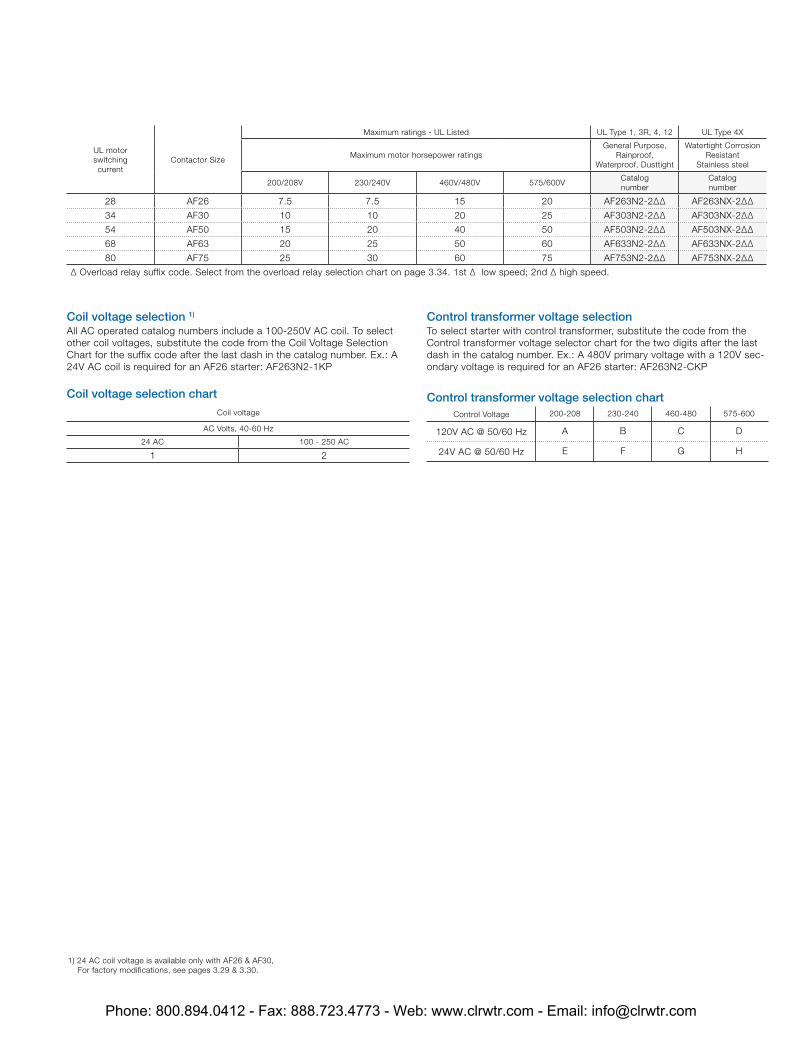
28 AF26 7.5 7.5 15 20 AF2632-2∆∆ AF263X-2∆∆
34 AF30 10 10 20 25 AF3032-2∆∆ AF303X-2∆∆
54 AF50 15 20 40 50 AF5032-2∆∆ AF503X-2∆∆
68 AF63 20 25 50 60 AF6332-2∆∆ AF633X-2∆∆
80 AF75 25 30 60 75 AF7532-2∆∆ AF753X-2∆∆
∆ Overload relay suffix code. Select from the overload relay selection chart on page 3.34. 1st ∆ low speed; 2nd ∆ high speed.
Coil voltage selection 1) All AC operated catalog numbers include a 100-250V AC coil. To select other coil voltages, substitute the code from the Coil Voltage Selection Chart for the suffix code after the last dash in the catalog number. Ex.: A 24V AC coil is required for an AF26 starter: AF2632-1KP
Coil voltage selection chartCoil voltage
AC Volts, 40-60 Hz
24 AC 100 - 250 AC
1 2
Control transformer voltage selection chartControl Voltage 200-208 230-240 460-480 575-600
120V AC @ 50/60 Hz A B C D
24V AC @ 50/60 Hz E F G H
Control transformer voltage selection To select starter with control transformer, substitute the code from the Control transformer voltage selector chart for the two digits after the last dash in the catalog number. Ex.: A 480V primary voltage with a 120V sec-ondary voltage is required for an AF26 starter: AF2632-CKP
1) 24 AC coil voltage is available only with AF26 & AF30, For factory modifications, see pages 3.29 & 3.30.
Phone: 800.894.0412 - Fax: 888.723.4773 - Web: www.clrwtr.com - Email: [email protected]
UL motor switching current
Contactor Size
Maximum ratings - UL Listed UL Type 1, 3R, 4, 12 UL Type 4X
Maximum motor horsepower ratingsGeneral Purpose,
Rainproof, Waterproof, Dusttight
Watertight Corrosion Resistant
Stainless steel
200/208V 230/240V 460V/480V 575/600VCatalognumber
Catalognumber
28 AF26 7.5 7.5 15 20 AF263N2-2∆∆ AF263NX-2∆∆
34 AF30 10 10 20 25 AF303N2-2∆∆ AF303NX-2∆∆
54 AF50 15 20 40 50 AF503N2-2∆∆ AF503NX-2∆∆
68 AF63 20 25 50 60 AF633N2-2∆∆ AF633NX-2∆∆
80 AF75 25 30 60 75 AF753N2-2∆∆ AF753NX-2∆∆
∆ Overload relay suffix code. Select from the overload relay selection chart on page 3.34. 1st ∆ low speed; 2nd ∆ high speed.
Coil voltage selection 1) All AC operated catalog numbers include a 100-250V AC coil. To select other coil voltages, substitute the code from the Coil Voltage Selection Chart for the suffix code after the last dash in the catalog number. Ex.: A 24V AC coil is required for an AF26 starter: AF263N2-1KP
Coil voltage selection chartCoil voltage
AC Volts, 40-60 Hz
24 AC 100 - 250 AC
1 2
Control transformer voltage selection chartControl Voltage 200-208 230-240 460-480 575-600
120V AC @ 50/60 Hz A B C D
24V AC @ 50/60 Hz E F G H
Control transformer voltage selection To select starter with control transformer, substitute the code from the Control transformer voltage selector chart for the two digits after the last dash in the catalog number. Ex.: A 480V primary voltage with a 120V sec-ondary voltage is required for an AF26 starter: AF263N2-CKP
1) 24 AC coil voltage is available only with AF26 & AF30, For factory modifications, see pages 3.29 & 3.30.
Phone: 800.894.0412 - Fax: 888.723.4773 - Web: www.clrwtr.com - Email: [email protected]
Coil voltage
AC Volts, 40-60 Hz
24 AC 100 - 250 AC
1 2
Control transformer voltage selection chartControl Voltage 200-208 230-240 460-480 575-600
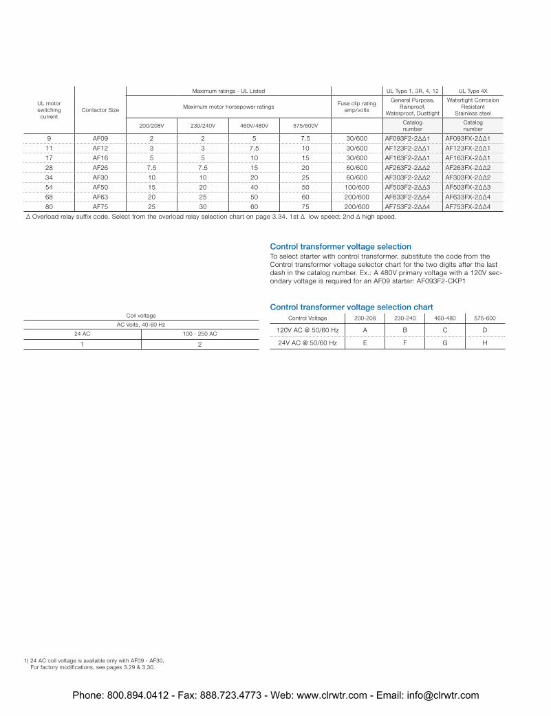
120V AC @ 50/60 Hz A B C D
24V AC @ 50/60 Hz E F G H
Control transformer voltage selection To select starter with control transformer, substitute the code from the Control transformer voltage selector chart for the two digits after the last dash in the catalog number. Ex.: A 480V primary voltage with a 120V sec-ondary voltage is required for an AF09 starter: AF093F2-CKP1
UL motor switching current
Contactor Size
Maximum ratings - UL Listed UL Type 1, 3R, 4, 12 UL Type 4X
Maximum motor horsepower ratingsFuse clip rating
amp/volts
General Purpose, Rainproof,
Waterproof, Dusttight
Watertight Corrosion Resistant
Stainless steel
200/208V 230/240V 460V/480V 575/600VCatalognumber
Catalognumber
9 AF09 2 2 5 7.5 30/600 AF093F2-2∆∆1 AF093FX-2∆∆1
11 AF12 3 3 7.5 10 30/600 AF123F2-2∆∆1 AF123FX-2∆∆1
17 AF16 5 5 10 15 30/600 AF163F2-2∆∆1 AF163FX-2∆∆1
28 AF26 7.5 7.5 15 20 60/600 AF263F2-2∆∆2 AF263FX-2∆∆2
34 AF30 10 10 20 25 60/600 AF303F2-2∆∆2 AF303FX-2∆∆2
54 AF50 15 20 40 50 100/600 AF503F2-2∆∆3 AF503FX-2∆∆3
68 AF63 20 25 50 60 200/600 AF633F2-2∆∆4 AF633FX-2∆∆4
80 AF75 25 30 60 75 200/600 AF753F2-2∆∆4 AF753FX-2∆∆4
∆ Overload relay suffix code. Select from the overload relay selection chart on page 3.34. 1st ∆ low speed; 2nd ∆ high speed.
1) 24 AC coil voltage is available only with AF09 - AF30, For factory modifications, see pages 3.29 & 3.30.
Phone: 800.894.0412 - Fax: 888.723.4773 - Web: www.clrwtr.com - Email: [email protected]
Coil voltage
AC Volts, 40-60 Hz
24 AC 100 - 250 AC
1 2
Control transformer voltage selection chartControl Voltage 200-208 230-240 460-480 575-600
120V AC @ 50/60 Hz A B C D
24V AC @ 50/60 Hz E F G H
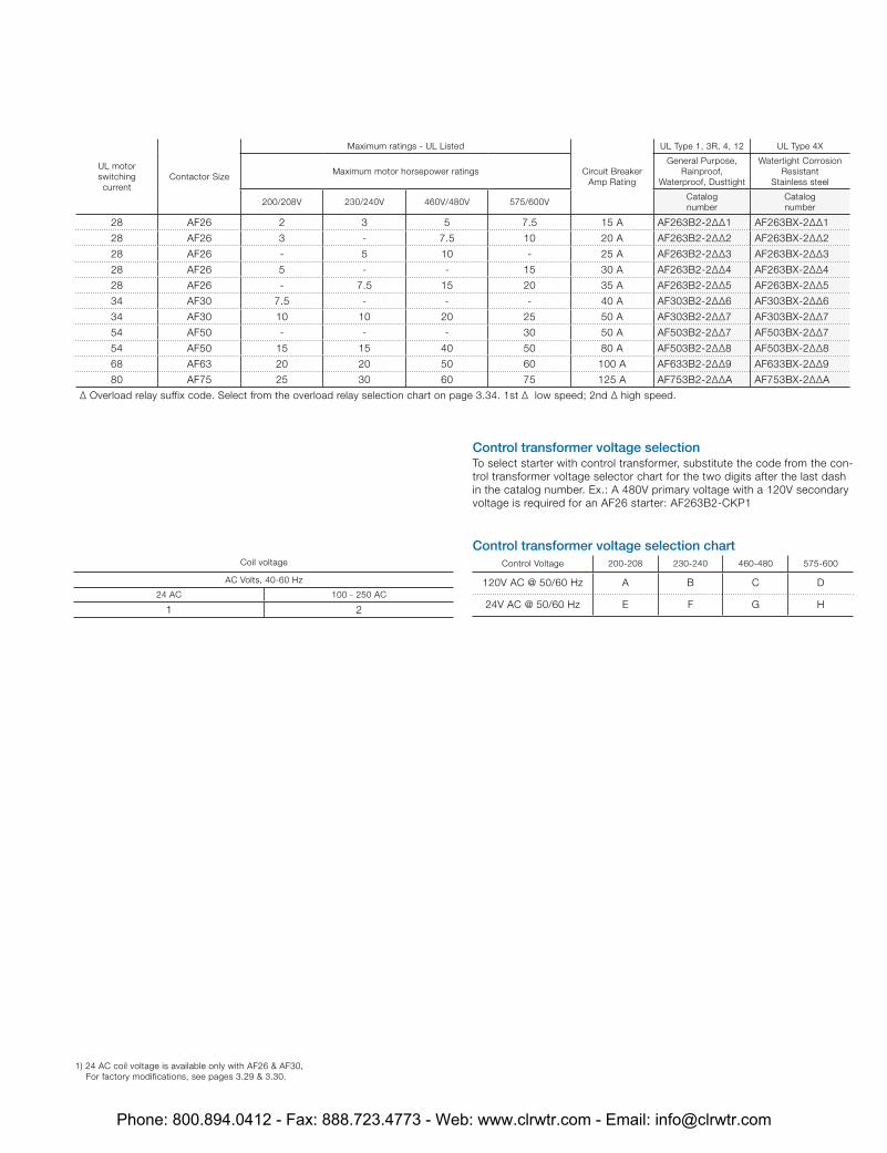
Control transformer voltage selection To select starter with control transformer, substitute the code from the con-trol transformer voltage selector chart for the two digits after the last dash in the catalog number. Ex.: A 480V primary voltage with a 120V secondary voltage is required for an AF26 starter: AF263B2-CKP1
UL motor switching current
Contactor Size
Maximum ratings - UL Listed
Circuit Breaker Amp Rating
UL Type 1, 3R, 4, 12 UL Type 4X
Maximum motor horsepower ratingsGeneral Purpose,
Rainproof, Waterproof, Dusttight
Watertight Corrosion Resistant
Stainless steel
200/208V 230/240V 460V/480V 575/600VCatalognumber
Catalognumber
28 AF26 2 3 5 7.5 15 A AF263B2-2∆∆1 AF263BX-2∆∆1
28 AF26 3 - 7.5 10 20 A AF263B2-2∆∆2 AF263BX-2∆∆2
28 AF26 - 5 10 - 25 A AF263B2-2∆∆3 AF263BX-2∆∆3
28 AF26 5 - - 15 30 A AF263B2-2∆∆4 AF263BX-2∆∆4
28 AF26 - 7.5 15 20 35 A AF263B2-2∆∆5 AF263BX-2∆∆5
34 AF30 7.5 - - - 40 A AF303B2-2∆∆6 AF303BX-2∆∆6
34 AF30 10 10 20 25 50 A AF303B2-2∆∆7 AF303BX-2∆∆7
54 AF50 - - - 30 50 A AF503B2-2∆∆7 AF503BX-2∆∆7
54 AF50 15 15 40 50 80 A AF503B2-2∆∆8 AF503BX-2∆∆8
68 AF63 20 20 50 60 100 A AF633B2-2∆∆9 AF633BX-2∆∆9
80 AF75 25 30 60 75 125 A AF753B2-2∆∆A AF753BX-2∆∆A
∆ Overload relay suffix code. Select from the overload relay selection chart on page 3.34. 1st ∆ low speed; 2nd ∆ high speed.
1) 24 AC coil voltage is available only with AF26 & AF30, For factory modifications, see pages 3.29 & 3.30.
Phone: 800.894.0412 - Fax: 888.723.4773 - Web: www.clrwtr.com - Email: [email protected]
UL motor switching current
Contactor Size
Maximum ratings - UL Listed UL Type 1, 3R, 4, 12 UL Type 4X
Maximum motor horsepower ratingsGeneral Purpose,
Rainproof, Waterproof, Dusttight
Watertight Corrosion Resistant
Stainless steel
200/208V 230/240V 460V/480V 575/600VCatalognumber
Catalognumber
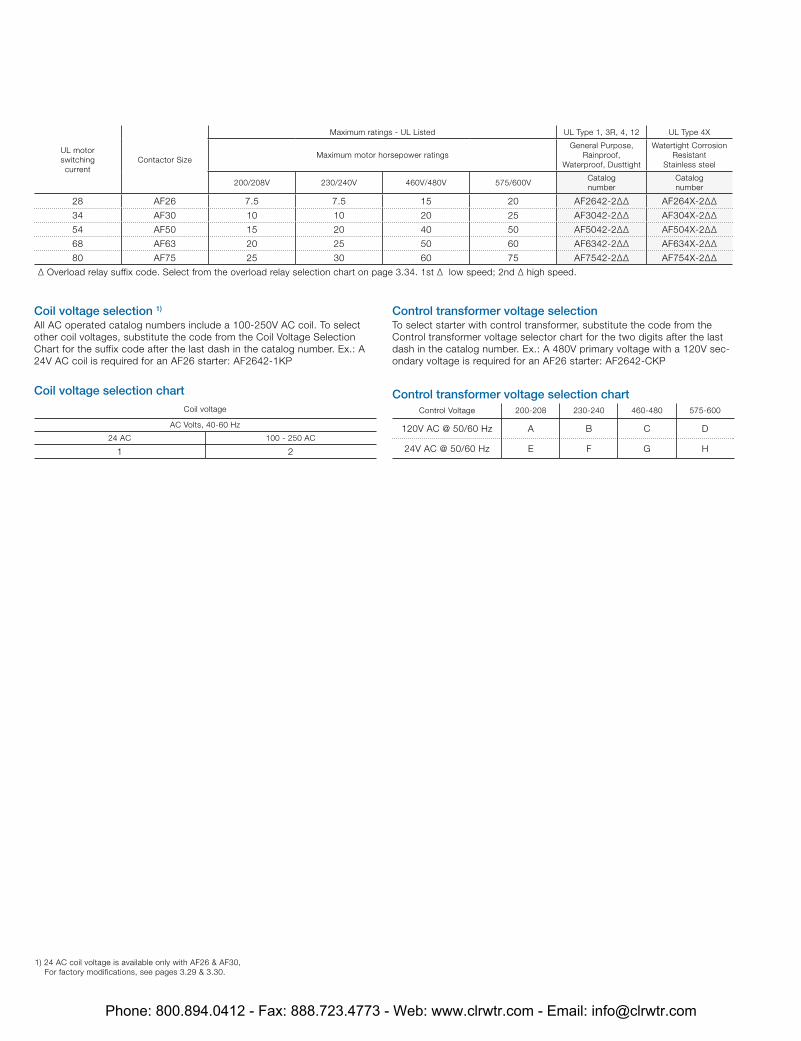
28 AF26 7.5 7.5 15 20 AF2642-2∆∆ AF264X-2∆∆
34 AF30 10 10 20 25 AF3042-2∆∆ AF304X-2∆∆
54 AF50 15 20 40 50 AF5042-2∆∆ AF504X-2∆∆
68 AF63 20 25 50 60 AF6342-2∆∆ AF634X-2∆∆
80 AF75 25 30 60 75 AF7542-2∆∆ AF754X-2∆∆
∆ Overload relay suffix code. Select from the overload relay selection chart on page 3.34. 1st ∆ low speed; 2nd ∆ high speed.
Coil voltage selection 1) All AC operated catalog numbers include a 100-250V AC coil. To select other coil voltages, substitute the code from the Coil Voltage Selection Chart for the suffix code after the last dash in the catalog number. Ex.: A 24V AC coil is required for an AF26 starter: AF2642-1KP
Coil voltage selection chartCoil voltage
AC Volts, 40-60 Hz
24 AC 100 - 250 AC
1 2
Control transformer voltage selection chartControl Voltage 200-208 230-240 460-480 575-600
120V AC @ 50/60 Hz A B C D
24V AC @ 50/60 Hz E F G H
Control transformer voltage selection To select starter with control transformer, substitute the code from the Control transformer voltage selector chart for the two digits after the last dash in the catalog number. Ex.: A 480V primary voltage with a 120V sec-ondary voltage is required for an AF26 starter: AF2642-CKP
1) 24 AC coil voltage is available only with AF26 & AF30, For factory modifications, see pages 3.29 & 3.30.
Phone: 800.894.0412 - Fax: 888.723.4773 - Web: www.clrwtr.com - Email: [email protected]
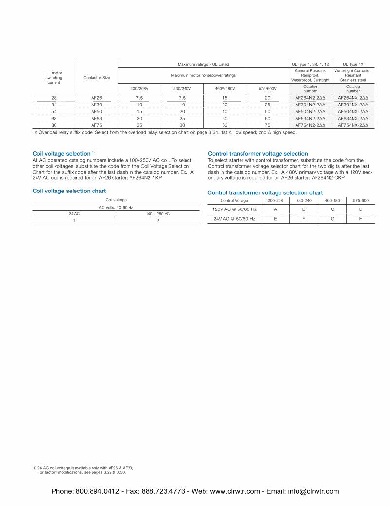
UL motor switching current
Contactor Size
Maximum ratings - UL Listed UL Type 1, 3R, 4, 12 UL Type 4X
Maximum motor horsepower ratingsGeneral Purpose,
Rainproof, Waterproof, Dusttight
Watertight Corrosion Resistant
Stainless steel
200/208V 230/240V 460V/480V 575/600VCatalognumber
Catalognumber
28 AF26 7.5 7.5 15 20 AF264N2-2∆∆ AF264NX-2∆∆
34 AF30 10 10 20 25 AF304N2-2∆∆ AF304NX-2∆∆
54 AF50 15 20 40 50 AF504N2-2∆∆ AF504NX-2∆∆
68 AF63 20 25 50 60 AF634N2-2∆∆ AF634NX-2∆∆
80 AF75 25 30 60 75 AF754N2-2∆∆ AF754NX-2∆∆
∆ Overload relay suffix code. Select from the overload relay selection chart on page 3.34. 1st ∆ low speed; 2nd ∆ high speed.
Coil voltage selection 1) All AC operated catalog numbers include a 100-250V AC coil. To select other coil voltages, substitute the code from the Coil Voltage Selection Chart for the suffix code after the last dash in the catalog number. Ex.: A 24V AC coil is required for an AF26 starter: AF264N2-1KP
Coil voltage selection chartCoil voltage
AC Volts, 40-60 Hz
24 AC 100 - 250 AC
1 2
Control transformer voltage selection chartControl Voltage 200-208 230-240 460-480 575-600
120V AC @ 50/60 Hz A B C D
24V AC @ 50/60 Hz E F G H
Control transformer voltage selection To select starter with control transformer, substitute the code from the Control transformer voltage selector chart for the two digits after the last dash in the catalog number. Ex.: A 480V primary voltage with a 120V sec-ondary voltage is required for an AF26 starter: AF264N2-CKP
1) 24 AC coil voltage is available only with AF26 & AF30, For factory modifications, see pages 3.29 & 3.30.
Phone: 800.894.0412 - Fax: 888.723.4773 - Web: www.clrwtr.com - Email: [email protected]
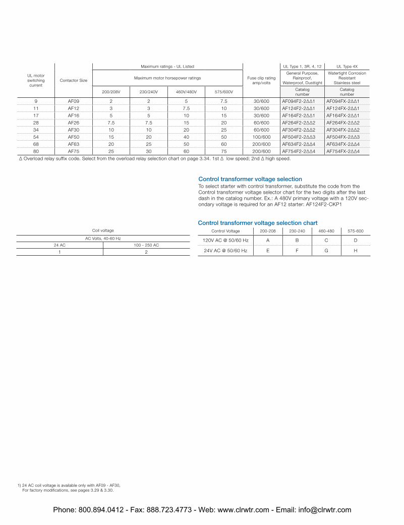
Coil voltage
AC Volts, 40-60 Hz
24 AC 100 - 250 AC
1 2
Control transformer voltage selection chartControl Voltage 200-208 230-240 460-480 575-600
120V AC @ 50/60 Hz A B C D
24V AC @ 50/60 Hz E F G H
Control transformer voltage selection To select starter with control transformer, substitute the code from the Control transformer voltage selector chart for the two digits after the last dash in the catalog number. Ex.: A 480V primary voltage with a 120V sec-ondary voltage is required for an AF12 starter: AF124F2-CKP1
UL motor switching current
Contactor Size
Maximum ratings - UL Listed
Fuse clip rating amp/volts
UL Type 1, 3R, 4, 12 UL Type 4X
Maximum motor horsepower ratingsGeneral Purpose,
Rainproof, Waterproof, Dusttight
Watertight Corrosion Resistant
Stainless steel
200/208V 230/240V 460V/480V 575/600VCatalognumber
Catalognumber
9 AF09 2 2 5 7.5 30/600 AF094F2-2∆∆1 AF094FX-2∆∆1
11 AF12 3 3 7.5 10 30/600 AF124F2-2∆∆1 AF124FX-2∆∆1
17 AF16 5 5 10 15 30/600 AF164F2-2∆∆1 AF164FX-2∆∆1
28 AF26 7.5 7.5 15 20 60/600 AF264F2-2∆∆2 AF264FX-2∆∆2
34 AF30 10 10 20 25 60/600 AF304F2-2∆∆2 AF304FX-2∆∆2
54 AF50 15 20 40 50 100/600 AF504F2-2∆∆3 AF504FX-2∆∆3
68 AF63 20 25 50 60 200/600 AF634F2-2∆∆4 AF634FX-2∆∆4
80 AF75 25 30 60 75 200/600 AF754F2-2∆∆4 AF754FX-2∆∆4
∆ Overload relay suffix code. Select from the overload relay selection chart on page 3.34. 1st ∆ low speed; 2nd ∆ high speed.
1) 24 AC coil voltage is available only with AF09 - AF30, For factory modifications, see pages 3.29 & 3.30.
Phone: 800.894.0412 - Fax: 888.723.4773 - Web: www.clrwtr.com - Email: [email protected]
Coil voltage
AC Volts, 40-60 Hz
24 AC 100 - 250 AC
1 2
Control transformer voltage selection chartControl Voltage 200-208 230-240 460-480 575-600
120V AC @ 50/60 Hz A B C D
24V AC @ 50/60 Hz E F G H
Control transformer voltage selection To select starter with control transformer, substitute the code from the Control transformer voltage selector chart for the two digits after the last dash in the catalog number. Ex.: A 480V primary voltage with a 120V sec-ondary voltage is required for an AF26 starter: AF264B2-CKP1
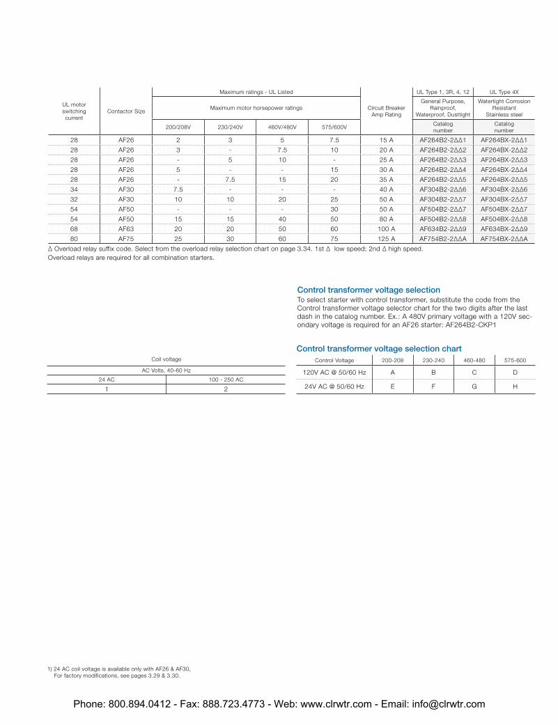
UL motor switching current
Contactor Size
Maximum ratings - UL Listed
Circuit Breaker Amp Rating
UL Type 1, 3R, 4, 12 UL Type 4X
Maximum motor horsepower ratingsGeneral Purpose,
Rainproof, Waterproof, Dusttight
Watertight Corrosion Resistant
Stainless steel
200/208V 230/240V 460V/480V 575/600VCatalognumber
Catalognumber
28 AF26 2 3 5 7.5 15 A AF264B2-2∆∆1 AF264BX-2∆∆1
28 AF26 3 - 7.5 10 20 A AF264B2-2∆∆2 AF264BX-2∆∆2
28 AF26 - 5 10 - 25 A AF264B2-2∆∆3 AF264BX-2∆∆3
28 AF26 5 - - 15 30 A AF264B2-2∆∆4 AF264BX-2∆∆4
28 AF26 - 7.5 15 20 35 A AF264B2-2∆∆5 AF264BX-2∆∆5
34 AF30 7.5 - - - 40 A AF304B2-2∆∆6 AF304BX-2∆∆6
32 AF30 10 10 20 25 50 A AF304B2-2∆∆7 AF304BX-2∆∆7
54 AF50 - - - 30 50 A AF504B2-2∆∆7 AF504BX-2∆∆7
54 AF50 15 15 40 50 80 A AF504B2-2∆∆8 AF504BX-2∆∆8
68 AF63 20 20 50 60 100 A AF634B2-2∆∆9 AF634BX-2∆∆9
80 AF75 25 30 60 75 125 A AF754B2-2∆∆A AF754BX-2∆∆A
∆ Overload relay suffix code. Select from the overload relay selection chart on page 3.34. 1st ∆ low speed; 2nd ∆ high speed.Overload relays are required for all combination starters.
1) 24 AC coil voltage is available only with AF26 & AF30, For factory modifications, see pages 3.29 & 3.30.
Phone: 800.894.0412 - Fax: 888.723.4773 - Web: www.clrwtr.com - Email: [email protected]
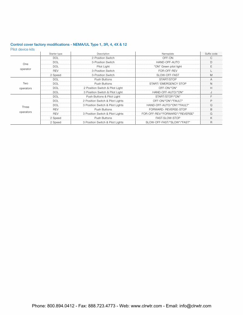
Control cover factory modifications - NEMA/UL Type 1, 3R, 4, 4X & 12Pilot device kits
Starter type Description Nameplate Suffix code
One
operator
DOL 2-Position Switch OFF-ON C
DOL 3-Position Switch HAND-OFF-AUTO D
DOL Pilot Light "ON" Green pilot light E
REV 3-Position Switch FOR-OFF-REV L
2 Speed 3-Position Switch SLOW-OFF-FAST M
Two
operators
DOL Push Buttons START/STOP A
DOL Push Buttons START/ EMERGENCY STOP N
DOL 2 Position Switch & Pilot Light OFF-ON/"ON" H
DOL 3 Position Switch & Pilot Light HAND-OFF-AUTO/"ON" J
Three
operators
DOL Push Buttons & Pilot Light START/STOP/"ON" F
DOL 2 Position Switch & Pilot Lights OFF-ON/"ON"/"FAULT" P
DOL 3 Position Switch & Pilot Lights HAND-OFF-AUTO/"ON"/"FAULT" Q
REV Push Buttons FORWARD- REVERSE-STOP B
REV 3 Position Switch & Pilot Lights FOR-OFF-REV/"FORWARD"/"REVERSE" G
2 Speed Push Buttons FAST-SLOW-STOP K
2 Speed 3 Position Switch & Pilot Lights SLOW-OFF-FAST/"SLOW"/"FAST" R
Phone: 800.894.0412 - Fax: 888.723.4773 - Web: www.clrwtr.com - Email: [email protected]
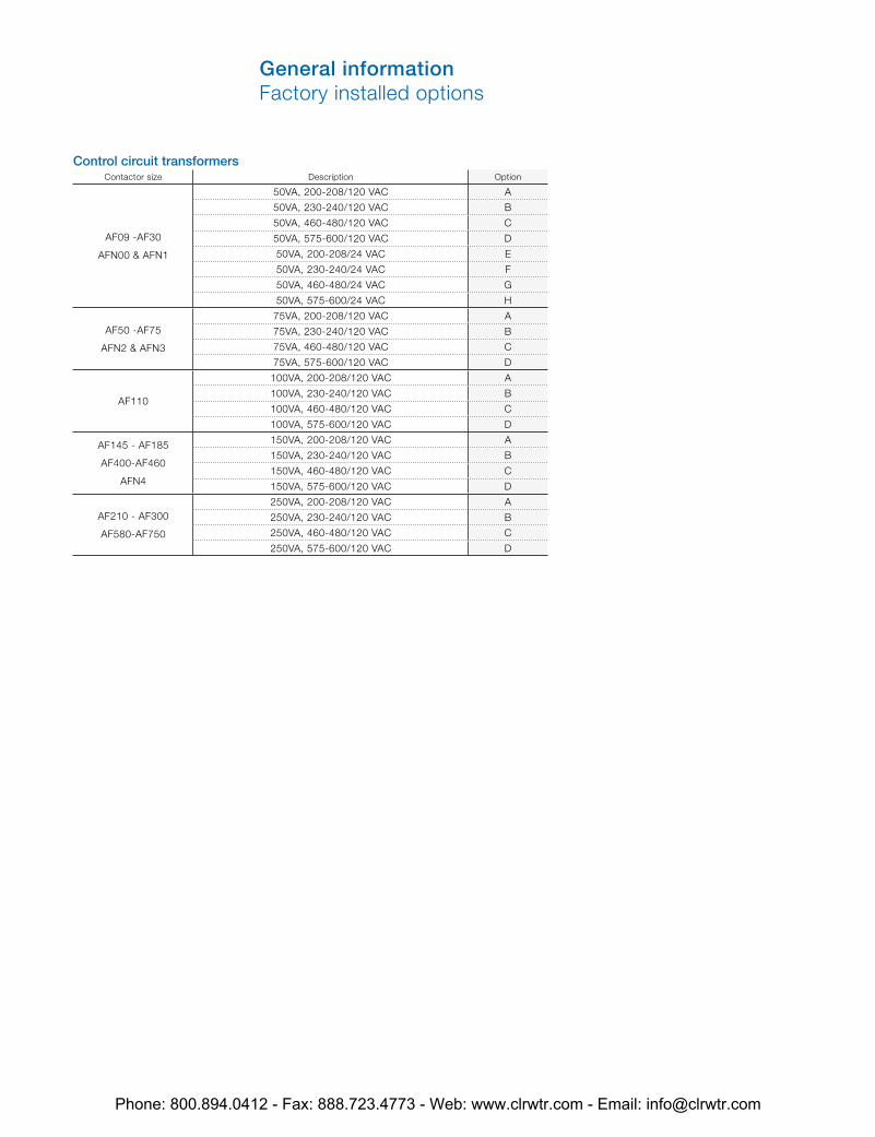
Control circuit transformersContactor size Description Option
AF09 -AF30
AFN00 & AFN1
50VA, 200-208/120 VAC A
50VA, 230-240/120 VAC B
50VA, 460-480/120 VAC C
50VA, 575-600/120 VAC D
50VA, 200-208/24 VAC E
50VA, 230-240/24 VAC F
50VA, 460-480/24 VAC G
50VA, 575-600/24 VAC H
AF50 -AF75
AFN2 & AFN3
75VA, 200-208/120 VAC A
75VA, 230-240/120 VAC B
75VA, 460-480/120 VAC C
75VA, 575-600/120 VAC D
AF110
100VA, 200-208/120 VAC A
100VA, 230-240/120 VAC B
100VA, 460-480/120 VAC C
100VA, 575-600/120 VAC D
AF145 - AF185
AF400-AF460
AFN4
150VA, 200-208/120 VAC A
150VA, 230-240/120 VAC B
150VA, 460-480/120 VAC C
150VA, 575-600/120 VAC D
AF210 - AF300
AF580-AF750
250VA, 200-208/120 VAC A
250VA, 230-240/120 VAC B
250VA, 460-480/120 VAC C
250VA, 575-600/120 VAC D
General informationFactory installed options
Phone: 800.894.0412 - Fax: 888.723.4773 - Web: www.clrwtr.com - Email: [email protected]
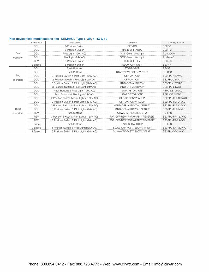
Pilot device field modifications kits- NEMA/UL Type 1, 3R, 4, 4X & 12 Starter type Description Nameplate Catalog number
One
operator
DOL 2-Position Switch OFF-ON SS2P-1
DOL 3-Position Switch HAND-OFF-AUTO SS3P-2
DOL Pilot Light (120V AC) "ON" Green pilot light PL-120VAC
DOL Pilot Light (24V AC) "ON" Green pilot light PL-24VAC
REV 3-Position Switch FOR-OFF-REV SS3P-3
2 Speed 3-Position Switch SLOW-OFF-FAST SS3P-4
Two
operators
DOL Push Buttons START/STOP PB-SS
DOL Push Buttons START/ EMERGENCY STOP PB-SES
DOL 2 Position Switch & Pilot Light (120V AC) OFF-ON/"ON" SS2PPL-120VAC
DOL 2 Position Switch & Pilot Light (24V AC) OFF-ON/"ON" SS2PPL-24VAC
DOL 3 Position Switch & Pilot Light (120V AC) HAND-OFF-AUTO/"ON" SS3PPL-120VAC
DOL 3 Position Switch & Pilot Light (24V AC) HAND-OFF-AUTO/"ON" SS3PPL-24VAC
Three
operators
DOL Push Buttons & Pilot Light (120V AC) START/STOP/"ON" PBPL-SS120VAC
DOL Push Buttons & Pilot Light (24V AC) START/STOP/"ON" PBPL-SS24VAC
DOL 2 Position Switch & Pilot Lights (120V AC) OFF-ON/"ON"/"FAULT" SS2PPL-FLT-120VAC
DOL 2 Position Switch & Pilot Lights (24V AC) OFF-ON/"ON"/"FAULT" SS2PPL-FLT-24VAC
DOL 3 Position Switch & Pilot Lights (120V AC) HAND-OFF-AUTO/"ON"/"FAULT" SS3PPL-FLT-120VAC
DOL 3 Position Switch & Pilot Lights (24V AC) HAND-OFF-AUTO/"ON"/"FAULT" SS3PPL-FLT-24VAC
REV Push Buttons FORWARD- REVERSE-STOP PB-FRS
REV 3 Position Switch & Pilot Lights (120V AC) FOR-OFF-REV/"FORWARD"/"REVERSE" SS3PPL-FR-120VAC
REV 3 Position Switch & Pilot Lights (24V AC) FOR-OFF-REV/"FORWARD"/"REVERSE" SS3PPL-FR-24VAC
2 Speed Push Buttons FAST-SLOW-STOP PB-FSS
2 Speed 3 Position Switch & Pilot Lights(120V AC) SLOW-OFF-FAST/"SLOW"/"FAST" SS3PPL-SF-120VAC
2 Speed 3 Position Switch & Pilot Lights (24V AC) SLOW-OFF-FAST/"SLOW"/"FAST" SS3PPL-SF-24VAC
Phone: 800.894.0412 - Fax: 888.723.4773 - Web: www.clrwtr.com - Email: [email protected]
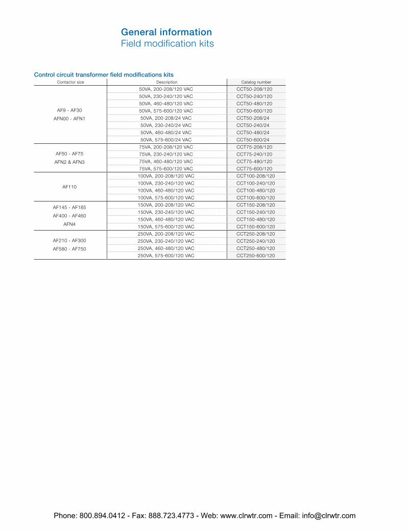
Control circuit transformer field modifications kits Contactor size Description Catalog number
AF9 - AF30
AFN00 - AFN1
50VA, 200-208/120 VAC CCT50-208/120
50VA, 230-240/120 VAC CCT50-240/120
50VA, 460-480/120 VAC CCT50-480/120
50VA, 575-600/120 VAC CCT50-600/120
50VA, 200-208/24 VAC CCT50-208/24
50VA, 230-240/24 VAC CCT50-240/24
50VA, 460-480/24 VAC CCT50-480/24
50VA, 575-600/24 VAC CCT50-600/24
AF50 - AF75
AFN2 & AFN3
75VA, 200-208/120 VAC CCT75-208/120
75VA, 230-240/120 VAC CCT75-240/120
75VA, 460-480/120 VAC CCT75-480/120
75VA, 575-600/120 VAC CCT75-600/120
AF110
100VA, 200-208/120 VAC CCT100-208/120
100VA, 230-240/120 VAC CCT100-240/120
100VA, 460-480/120 VAC CCT100-480/120
100VA, 575-600/120 VAC CCT100-600/120
AF145 - AF185
AF400 - AF460
AFN4
150VA, 200-208/120 VAC CCT150-208/120
150VA, 230-240/120 VAC CCT150-240/120
150VA, 460-480/120 VAC CCT150-480/120
150VA, 575-600/120 VAC CCT150-600/120
AF210 - AF300
AF580 - AF750
250VA, 200-208/120 VAC CCT250-208/120
250VA, 230-240/120 VAC CCT250-240/120
250VA, 460-480/120 VAC CCT250-480/120
250VA, 575-600/120 VAC CCT250-600/120
General informationField modification kits
Phone: 800.894.0412 - Fax: 888.723.4773 - Web: www.clrwtr.com - Email: [email protected]

1/10 3.0 — — 1.65 — — 1.5 — — 1.0 — — — — — — —
1/8 3.8 — — 2.1 — — 1.9 — — 1.2 — — — — — — —
1/6 4.4 — — 2.4 — — 2.2 — — 1.4 — — — — — — —
1/4 5.8 — — 3.2 — — 2.9 — — 1.8 — — — — — — —
1/3 7.2 — — 4.0 — — 3.6 — — 2.3 — — — — — — —
1/2 9.8 4.0 4.4 5.4 2.2 2.4 4.9 2.0 2.2 3.2 1.3 2.5 1.0 1.1 2.0 0.8 0.9
3/4 13.8 4.8 6.4 7.6 2.6 3.5 6.9 2.4 3.2 4.5 1.8 3.5 1.2 1.6 2.8 1.0 1.3
1 16.0 6.4 8.4 8.8 3.6 4.6 8.0 3.2 4.2 5.1 2.3 4.0 1.6 2.1 3.2 1.3 1.7
1 1/2 20.0 9.0 12.0 11.0 5.0 6.6 10.0 4.5 6.0 6.4 3.3 5.0 2.3 3.0 4.0 1.8 2.4
2 24.0 11.8 13.6 13.2 6.5 7.5 12.0 5.9 6.8 7.7 4.3 6.0 3.0 3.4 4.8 2.4 2.7
3 34.0 16.6 19.2 18.7 9.2 10.6 17.0 8.3 9.6 10.9 6.1 8.5 4.2 4.8 6.8 3.3 3.9
5 56.0 26.4 30.4 30.8 14.5 16.8 28.0 13.2 15.2 17.9 9.7 14.0 6.6 7.6 11.2 5.3 6.1
7 1/2 80.0 38.0 44.0 44.0 21.0 24.2 40.0 19.0 22.0 27.0 14.0 21.0 9.0 11.0 16.0 8.0 9.0
10 100.0 48.0 56.0 55.0 26.4 30.8 50.0 24.0 28.0 33.0 18.0 26.0 12.0 14.0. 20.0 10.0 11.0
15 135.0 72.0 84.0 75.0 39.6 46.2 68.0 36.0 42.0 44.0 27.0 34.0 18.0 21.0 27.0 14.0 17.0
20 — 94.0 108.0 96.8 52.0 60.0 88.0 47.0 54.0 56.0 34.0 44.0 23.0 27.0 35.0 19.0 22.0
25 — 118.0 136.0 121.0 65.0 75.0 110.0 59.0 68.0 70.0 44.0 55.0 29.0 34.0 44.0 24.0 27.0
30 — 138.0 160.0 150.0 76.0 88.0 136.0 69.0 80.0 87.0 51.0 68.0 35.0 40.0 54.0 28.0 32.0
40 — 180.0 208.0 194.0 100.0 115.0 176.0 90.0 104.0 112.0 66.0 88.0 45.0 52.0 70.0 36.0 41.0
50 — 226.0 260.0 238.0 125.0 143.0 216.0 113.0 130.0 139.0 83.0 108.0 56.0 65.0 86.0 45.0 52.0
60 — — — — 147.0 160.0 — 133.0 154.0 — 103.0 — 67.0 77.0 — 53.0 62.0
75 — — — — 183.0 212.0 — 166.0 192.0 — 128.0 — 83.0 96.0 — 66.0 77.0
100 — — — — 240.0 273.0 — 218.0 248.0 — 165.0 — 109.0 124.0 — 87.0 99.0
125 — — — — — 344.0 — — 312.0 — 208.0 — 135.0 156.0 — 108.0 125.0
150 — — — — — 396.0 — — 360.0 — 240.0 — 156.0 180.0 — 125.0 144.0
200 — — — — — 528.0 — — 480.0 — 320.0 — 208.0 240.0 — 167.0 192.0
250 — — — — — 663.0 — — 602.0 — 403.0 — — 302.0 — — 242.0
300 — — — — — — — — — — 482.0 — — 361.0 — — 289.0
350 — — — — — — — — — — 560.0 — — 414.0 — — 336.0
400 — — — — — — — — — — 636.0 — — 477.0 — — 382.0
500 — — — — — — — — — — 786.0 — — 590.0 — — 472.0
110 – 120V 200 – 208V 220 – 240V 380 – 415V1 440 – 480V 550 – 600V
Horse Single Two Three Single Two Three Single Two Three Single Three Single Two Three Single Two Three power phase phase phase phase phase phase phase phase phase phase phase phase phase phase phase phase phase
Ampere ratings of 3 phase, AC induction motors
Phone: 800.894.0412 - Fax: 888.723.4773 - Web: www.clrwtr.com - Email: [email protected]
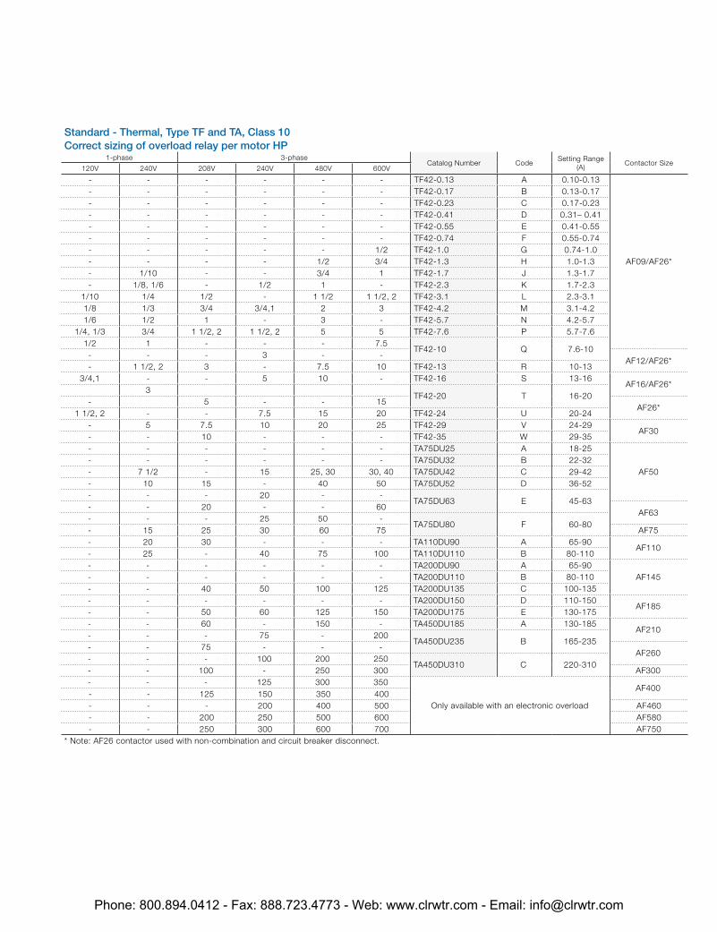
Standard - Thermal, Type TF and TA, Class 10Correct sizing of overload relay per motor HP
1-phase 3-phaseCatalog Number Code
Setting Range (A)
Contactor Size120V 240V 208V 240V 480V 600V
- - - - - - TF42-0.13 A 0.10-0.13
AF09/AF26*
- - - - - - TF42-0.17 B 0.13-0.17- - - - - - TF42-0.23 C 0.17-0.23- - - - - - TF42-0.41 D 0.31– 0.41- - - - - - TF42-0.55 E 0.41-0.55- - - - - - TF42-0.74 F 0.55-0.74- - - - - 1/2 TF42-1.0 G 0.74-1.0- - - - 1/2 3/4 TF42-1.3 H 1.0-1.3- 1/10 - - 3/4 1 TF42-1.7 J 1.3-1.7- 1/8, 1/6 - 1/2 1 - TF42-2.3 K 1.7-2.3
1/10 1/4 1/2 - 1 1/2 1 1/2, 2 TF42-3.1 L 2.3-3.11/8 1/3 3/4 3/4,1 2 3 TF42-4.2 M 3.1-4.21/6 1/2 1 - 3 - TF42-5.7 N 4.2-5.7
1/4, 1/3 3/4 1 1/2, 2 1 1/2, 2 5 5 TF42-7.6 P 5.7-7.61/2 1 - - - 7.5
TF42-10 Q 7.6-10- - - 3 - -
AF12/AF26*- 1 1/2, 2 3 - 7.5 10 TF42-13 R 10-13
3/4,1 - - 5 10 - TF42-16 S 13-16AF16/AF26*
3TF42-20 T 16-20
- 5 - - 15AF26*
1 1/2, 2 - - 7.5 15 20 TF42-24 U 20-24- 5 7.5 10 20 25 TF42-29 V 24-29
AF30- - 10 - - - TF42-35 W 29-35- - - - - - TA75DU25 A 18-25
AF50- - - - - - TA75DU32 B 22-32- 7 1/2 - 15 25, 30 30, 40 TA75DU42 C 29-42- 10 15 - 40 50 TA75DU52 D 36-52- - - 20 - -
TA75DU63 E 45-63- - 20 - - 60
AF63- - - 25 50 -
TA75DU80 F 60-80- 15 25 30 60 75 AF75- 20 30 - - - TA110DU90 A 65-90
AF110- 25 - 40 75 100 TA110DU110 B 80-110- - - - - - TA200DU90 A 65-90
AF145- - - - - - TA200DU110 B 80-110- - 40 50 100 125 TA200DU135 C 100-135- - - - - - TA200DU150 D 110-150
AF185- - 50 60 125 150 TA200DU175 E 130-175- - 60 - 150 - TA450DU185 A 130-185
AF210- - - 75 - 200
TA450DU235 B 165-235- - 75 - - -
AF260- - - 100 200 250
TA450DU310 C 220-310- - 100 - 250 300 AF300- - - 125 300 350
Only available with an electronic overload
AF400- - 125 150 350 400- - - 200 400 500 AF460- - 200 250 500 600 AF580- - 250 300 600 700 AF750
* Note: AF26 contactor used with non-combination and circuit breaker disconnect.
Phone: 800.894.0412 - Fax: 888.723.4773 - Web: www.clrwtr.com - Email: [email protected]
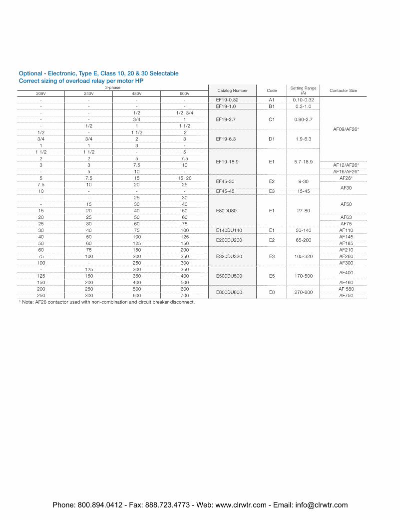
Optional - Electronic, Type E, Class 10, 20 & 30 SelectableCorrect sizing of overload relay per motor HP
3-phaseCatalog Number Code
Setting Range (A)
Contactor Size208V 240V 480V 600V
- - - - EF19-0.32 A1 0.10-0.32
AF09/AF26*
- - - - EF19-1.0 B1 0.3-1.0- - 1/2 1/2, 3/4
EF19-2.7 C1 0.80-2.7- - 3/4 1- 1/2 1 1 1/2
1/2 - 1 1/2 2EF19-6.3 D1 1.9-6.33/4 3/4 2 3
1 1 3 -1 1/2 1 1/2 - 5
EF19-18.9 E1 5.7-18.92 2 5 7.53 3 7.5 10 AF12/AF26*- 5 10 - AF16/AF26*5 7.5 15 15, 20
EF45-30 E2 9-30AF26*
7.5 10 20 25AF30
10 - - - EF45-45 E3 15-45- - 25 30
E80DU80 E1 27-80AF50- 15 30 40
15 20 40 5020 25 50 60 AF6325 30 60 75 AF7530 40 75 100 E140DU140 E1 50-140 AF11040 50 100 125
E200DU200 E2 65-200AF145
50 60 125 150 AF18560 75 150 200
E320DU320 E3 105-320AF210
75 100 200 250 AF260100 - 250 300 AF300
- 125 300 350E500DU500 E5 170-500
AF400125 150 350 400150 200 400 500 AF460200 250 500 600
E800DU800 E8 270-800AF 580
250 300 600 700 AF750* Note: AF26 contactor used with non-combination and circuit breaker disconnect.
Phone: 800.894.0412 - Fax: 888.723.4773 - Web: www.clrwtr.com - Email: [email protected]
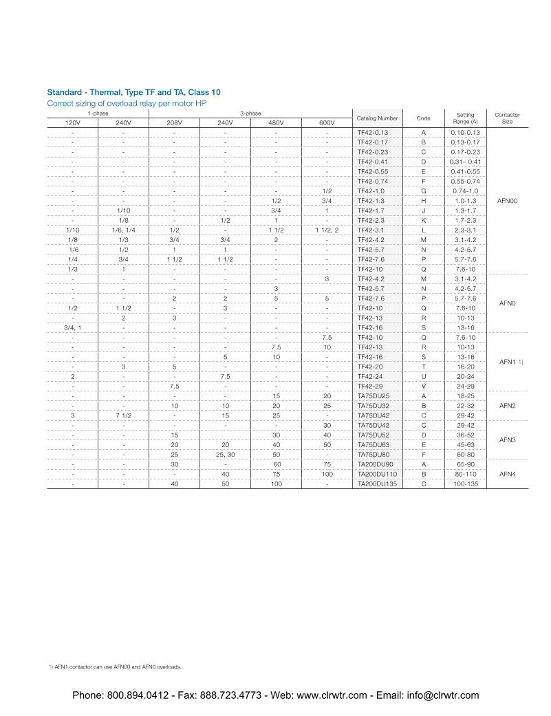
Standard - Thermal, Type TF and TA, Class 10Correct sizing of overload relay per motor HP
1-phase 3-phaseCatalog Number Code
Setting Range (A)
Contactor Size120V 240V 208V 240V 480V 600V
- - - - - - TF42-0.13 A 0.10-0.13
AFN00
- - - - - - TF42-0.17 B 0.13-0.17
- - - - - - TF42-0.23 C 0.17-0.23
- - - - - - TF42-0.41 D 0.31– 0.41
- - - - - - TF42-0.55 E 0.41-0.55
- - - - - - TF42-0.74 F 0.55-0.74
- - - - - 1/2 TF42-1.0 G 0.74-1.0
- - - - 1/2 3/4 TF42-1.3 H 1.0-1.3
- 1/10 - - 3/4 1 TF42-1.7 J 1.3-1.7
- 1/8 - 1/2 1 - TF42-2.3 K 1.7-2.3
1/10 1/6, 1/4 1/2 - 1 1/2 1 1/2, 2 TF42-3.1 L 2.3-3.1
1/8 1/3 3/4 3/4 2 - TF42-4.2 M 3.1-4.2
1/6 1/2 1 1 - - TF42-5.7 N 4.2-5.7
1/4 3/4 1 1/2 1 1/2 - - TF42-7.6 P 5.7-7.6
1/3 1 - - - - TF42-10 Q 7.6-10
- - - - - 3 TF42-4.2 M 3.1-4.2
AFN0
- - - - 3 TF42-5.7 N 4.2-5.7
- - 2 2 5 5 TF42-7.6 P 5.7-7.6
1/2 1 1/2 - 3 - - TF42-10 Q 7.6-10
- 2 3 - - - TF42-13 R 10-13
3/4, 1 - - - - - TF42-16 S 13-16
- - - - - 7.5 TF42-10 Q 7.6-10
AFN1 1)
- - - - 7.5 10 TF42-13 R 10-13
- - - 5 10 - TF42-16 S 13-16
- 3 5 - - - TF42-20 T 16-20
2 - - 7.5 - - TF42-24 U 20-24
- - 7.5 - - - TF42-29 V 24-29
- - - - 15 20 TA75DU25 A 18-25
AFN2- - 10 10 20 25 TA75DU32 B 22-32
3 7 1/2 - 15 25 - TA75DU42 C 29-42
- - - - - 30 TA75DU42 C 29-42
AFN3- - 15 30 40 TA75DU52 D 36-52
- - 20 20 40 50 TA75DU63 E 45-63
- - 25 25, 30 50 - TA75DU80 F 60-80
- - 30 - 60 75 TA200DU90 A 65-90
AFN4- - - 40 75 100 TA200DU110 B 80-110
- - 40 50 100 - TA200DU135 C 100-135
1) AFN1 contactor can use AFN00 and AFN0 overloads.
Phone: 800.894.0412 - Fax: 888.723.4773 - Web: www.clrwtr.com - Email: [email protected]
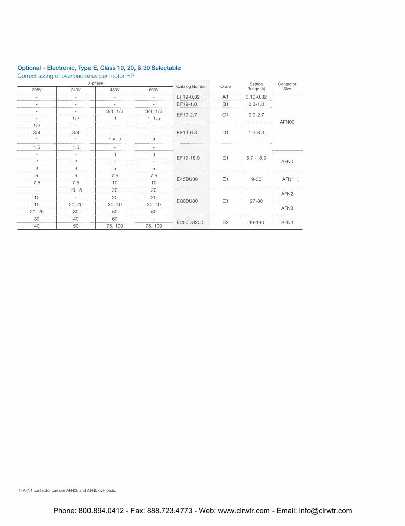
Optional - Electronic, Type E, Class 10, 20, & 30 SelectableCorrect sizing of overload relay per motor HP
3-phaseCatalog Number Code
Setting Range (A)
Contactor Size208V 240V 480V 600V
- - - - EF19-0.32 A1 0.10-0.32
AFN00
- - - - EF19-1.0 B1 0.3-1.0
- - 3/4, 1/2 3/4, 1/2EF19-2.7 C1 0.9-2.7
- 1/2 1 1, 1.5
1/2 - - -
EF19-6.3 D1 1.9-6.33/4 3/4 - -
1 1 1.5, 2 2
1.5 1.5 - -
EF19-18.9 E1 5.7 -18.9- - 3 3
AFN02 2 - -
3 3 5 5
5 5 7.5 7.5E45DU30 E1 9-30 AFN1 1)
7.5 7.5 10 10
- 10,15 20 20
E80DU80 E1 27-80
AFN210 - 25 25
15 20, 25 30, 40 30, 40AFN3
20, 25 30 50 50
30 40 60 -E200DU200 E2 40-140 AFN4
40 50 75, 100 75, 100
1) AFN1 contactor can use AFN00 and AFN0 overloads.
Phone: 800.894.0412 - Fax: 888.723.4773 - Web: www.clrwtr.com - Email: [email protected]

H
W D
IEC and NEMA startersNon reversing and reversing H H W W D D
Contactor Size Enclosure Type (in) (mm) (in) (mm) (in) (mm)
AF09-AF30, AFN00-AFN1
1, 3R, 4, 4X, 12
12 300 12 300 6 150
AF50-AF75, AFN3 16 400 12 300 8 200
AF110 24 600 20 500 10 250
AF145-AF185, AFN4 36 900 30 760 10 250
AF210-AF300 48 1200 36 900 12 300
AF400-AF460 48 1200 36 900 16 400
AF580-AF750 60 1500 60 1500 18 449
Two speed 1 winding & 2 winding AF09-AF30
1, 3R, 4, 4X, 12
16 400 12 300 8 200
AF50-AF75 20 500 16 400 8 200
AF110 24 600 20 500 10 250
AF145-AF185 36 900 30 760 10 250
AF210-AF300 48 1200 36 900 12 300
AF400-AF460 48 1200 36 900 16 400
AF580-AF750 60 1500 60 1500 18 449
Enclosure accessories for non-combination and combination controllers
Description Catalog number
12Hx16D Floormount Kit RC-FSK1212C
12Hx16D Floormount Kit RC-FSK1216C
12Hx12D Floormount Kit Type 304 SS RC-FSK12124
12Hx12D Floormount Kit Type 304 SS RC-FSK12164
Padlock lockout carbon steel 1) RC-WMPADRCS
Padlock lockout stainless steel 1) RC-WMPADRS6
Wallmount Bracket Kit RC-2508.200
Wallmount Bracket Kit Type 304 SS RC-2433.000
1) Used on enclosures below 36” in height.
Exact dimensions can be obtained using the on line configurator
Phone: 800.894.0412 - Fax: 888.723.4773 - Web: www.clrwtr.com - Email: [email protected]
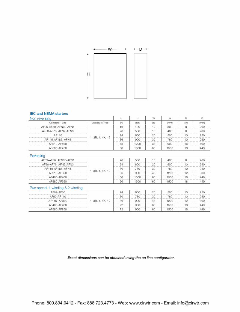
H
W D
IEC and NEMA startersNon reversing H H W W D D
Contactor Size Enclosure Type (in) (mm) (in) (mm) (in) (mm)
AF09-AF30, AFN00-AFN1
1, 3R, 4, 4X, 12
16 400 12 300 8 200
AF50-AF75, AFN2-AFN3 20 500 16 400 8 200
AF110 24 600 20 500 10 250
AF145-AF185, AFN4 36 900 30 760 10 250
AF210-AF460 48 1200 36 900 16 400
AF580-AF750 60 1500 60 1500 18 449
ReversingAF09-AF30, AFN00-AFN1
1, 3R, 4, 4X, 12
20 500 16 400 8 200
AF50-AF75, AFN2-AFN3 24 600 20 500 10 250
AF110-AF185, AFN4 30 760 30 760 10 250
AF210-AF300 36 900 48 1200 12 300
AF400-AF460 60 1500 60 1500 18 449
AF580-AF750 60 1500 60 1500 18 449
Two speed 1 winding & 2 winding AF09-AF30
1, 3R, 4, 4X, 12
24 600 20 500 10 250
AF50-AF110 30 760 30 760 10 250
AF145- AF300 36 900 48 1200 12 300
AF400-AF460 72 900 60 1500 18 449
AF580-AF750 72 900 60 1500 18 449
Exact dimensions can be obtained using the on line configurator
Phone: 800.894.0412 - Fax: 888.723.4773 - Web: www.clrwtr.com - Email: [email protected]
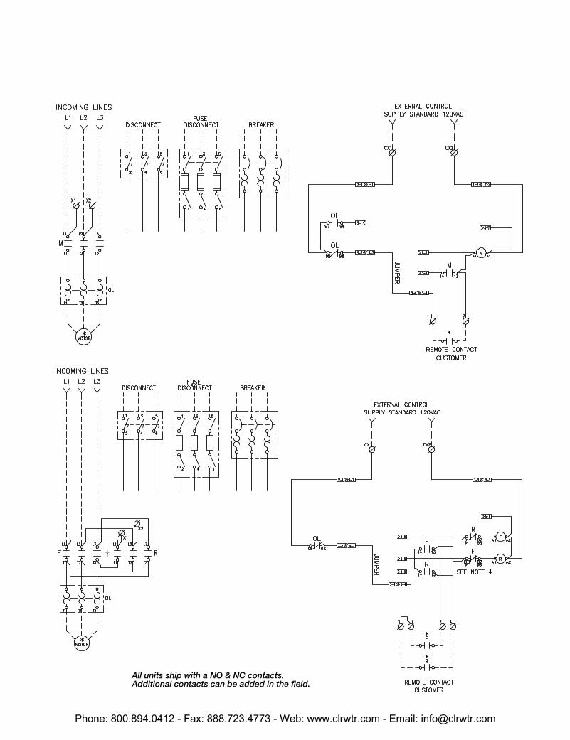
All units ship with a NO & NC contacts. Additional contacts can be added in the field.
Phone: 800.894.0412 - Fax: 888.723.4773 - Web: www.clrwtr.com - Email: [email protected]
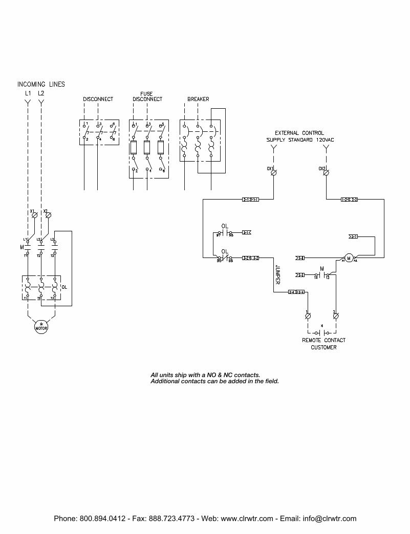
All units ship with a NO & NC contacts. Additional contacts can be added in the field.
Phone: 800.894.0412 - Fax: 888.723.4773 - Web: www.clrwtr.com - Email: [email protected]
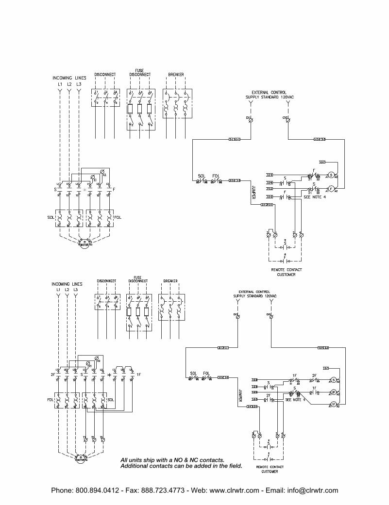
All units ship with a NO & NC contacts. Additional contacts can be added in the field.
Phone: 800.894.0412 - Fax: 888.723.4773 - Web: www.clrwtr.com - Email: [email protected]
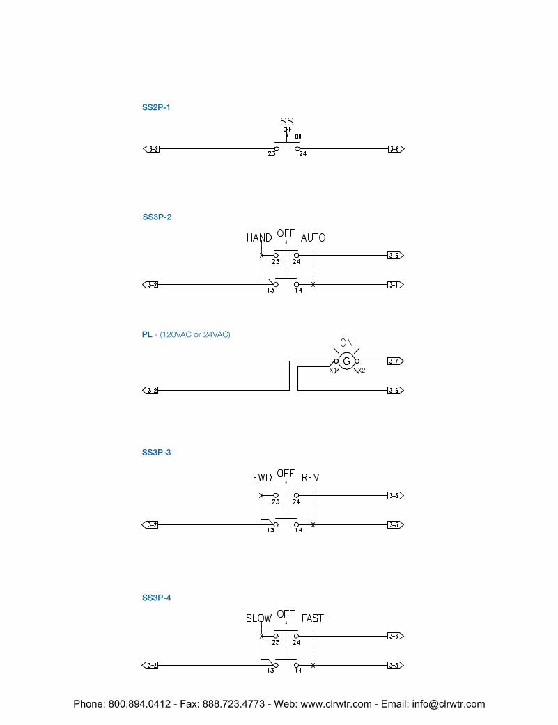
SS2P-1
SS3P-2
PL - (120VAC or 24VAC)
SS3P-3
SS3P-4
Phone: 800.894.0412 - Fax: 888.723.4773 - Web: www.clrwtr.com - Email: [email protected]
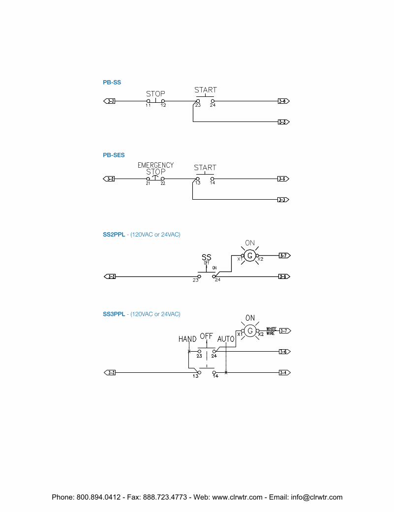
PB-SS
PB-SES
SS2PPL - (120VAC or 24VAC)
SS3PPL - (120VAC or 24VAC)
Phone: 800.894.0412 - Fax: 888.723.4773 - Web: www.clrwtr.com - Email: [email protected]
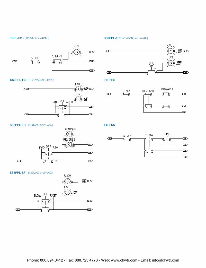
PBPL-SS - (120VAC or 24VAC)
SS3PPL-FLT - (120VAC or 24VAC)
SS3PPL-FR - (120VAC or 24VAC)
SS3PPL-SF - (120VAC or 24VAC)
SS2PPL-FLT - (120VAC or 24VAC)
PB-FRS
PB-FSS
Phone: 800.894.0412 - Fax: 888.723.4773 - Web: www.clrwtr.com - Email: [email protected]
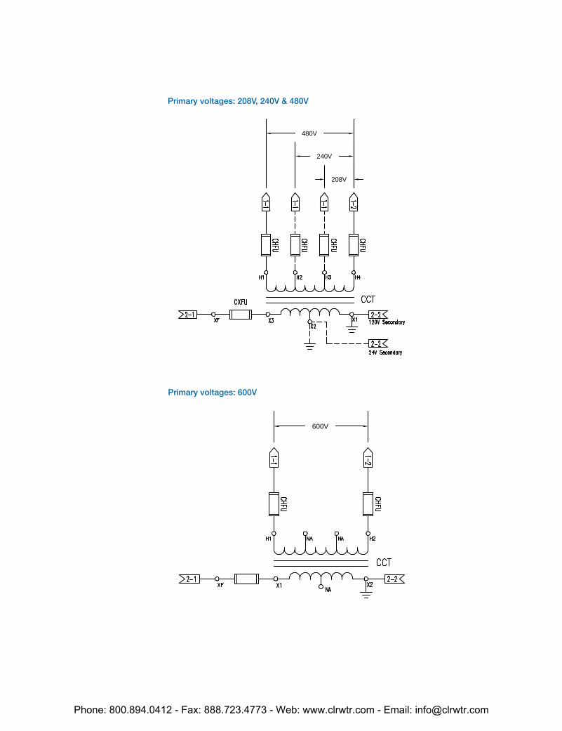
208V
240V
480V
600V
Primary voltages: 208V, 240V & 480V
Primary voltages: 600V
Phone: 800.894.0412 - Fax: 888.723.4773 - Web: www.clrwtr.com - Email: [email protected]

Type 1
Enclosures are intended for indoor use primarily to provide a degree of protec-tion against limited amounts of falling dirt. (NEMA Standard 7-15-1991.)
Type 3R
Enclosures are intended for outdoor use primar-ily to provide a degree of protection against rain, sleet and damage from external ice forma-tion. (NEMA Standard 7-15-1991.)
Type 4
Enclosures are intended for indoor or out-door use primarily to provide a degree of protection against windblown dust and rain, splashing water, hose-directed water and damage from external ice formation. (NEMA Standard 1-10-1979.)
Type 4X
Enclosures are intended for indoor or outdoor use primarily to provide a degree of protec-tion against corrosion, windblown dust and rain, splashing water, hose-directed water and damage from external ice formation. (NEMA Standard 1-10-1979)
Type 12
Enclosures are intended for indoor use primar-ily to provide a degree of protection against circulating dust, falling dirt, and dripping noncor-rosive liquids. (NEMA Standard 7-15-1991.)
Definitions pertaining to nonhazardous locations
IntroductionAn enclosure is a surrounding case constructed to provide a degree of protection to personnel against accidental contact with the enclosed equipment and to provide a degree of protection to the enclosed equip-ment against specified environmental conditions.
A brief description of the more common types of enclosures used by the electrical industry relating to their environmental capabilities follows. Refer to NEMA Standards Publication for more information regarding applications, features and design tests.
Individual NEMA product Standards Publications or third party certifica-tion standards may contain additional requirements for product testing and performance.
X
– Indoors
– Outdoors
– Water
– Dirt/dust
– Corrosion
Legend
Enclosure rating definitions
Phone: 800.894.0412 - Fax: 888.723.4773 - Web: www.clrwtr.com - Email: [email protected]
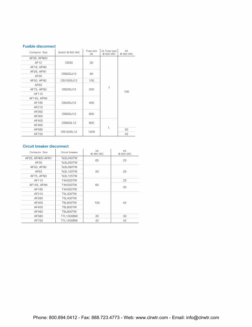
Fusible disconnect
Contactor Size Switch @ 600 VACFuse size
(A)UL Fuse type@ 600 VAC
kA@ 600 VAC
AF09, AFN00
OS30 30
J
100
AF12
AF16, AFN0
AF26, AFN1OS60GJ12 60
AF30
AF50, AFN2 OS100GJ12 100
AF63
OS200J12 200AF75, AFN3
AF110
AF145, AFN4
OS400J12 400AF185
AF210
AF260OS600J12 600
AF300
AF400OS800L12 800
LAF460
AF580OS1200L12 1200
30
AF750 42
Circuit breaker disconnect
Contactor Size Circuit breakerkA
@ 480 VACkA
@ 600 VAC
AF26, AFN00-AFN1 Ts3L040TW65 25
AF30 Ts3L050TW
AF50, AFN2 Ts3L090TW
50 25AF63 Ts3L100TW
AF75, AFN3 Ts3L125TW
AF110 T4H200TW
65
25
AF145, AFN4 T4H200TW35
AF185 T4H250TW
AF210 T5L300TW
100 42
AF260 T5L400TW
AF300 T6L600TW
AF400 T6L800TW
AF460 T6L800TW
AF580 T7L1000BW 30 30
AF750 T7L1200BW 42 42
Phone: 800.894.0412 - Fax: 888.723.4773 - Web: www.clrwtr.com - Email: [email protected]
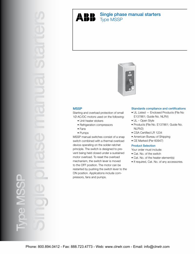
StartersSingle phase
Manual starters
Single phase manual startersType MSSP
Type
MS
SP
Sin
gle
phas
e m
anua
l sta
rters
MSSPStarting and overload protection of small 1Ø AC/DC motors used on the following:
• Unit heater stokers• Refrigeration compressors• Fans• Pumps
MSSP manual switches consist of a snap switch combined with a thermal overload device operating on the solder-ratchet principle. The switch is designed to pre-vent being held closed under a sustained motor overload. To reset the overload mechanism, the switch lever is movedto the OFF position. The motor can be restarted by pushing the switch lever to the ON position. Applications include com-pressors, fans and pumps.
Standards compliance and certifications• UL Listed — Enclosed Products (File No E137861; Guide No. NLRV)• UL – Open Style• Products (File No. E137861; Guide No. NLRV2)• CSA Certified LR 1234• American Bureau of Shipping• CE Marked (Per 60947)
Product SelectionYour order must include:• Cat. No. of the switch• Cat. No. of the heater element(s)• If required, Cat. No. of any accessories.
Phone: 800.894.0412 - Fax: 888.723.4773 - Web: www.clrwtr.com - Email: [email protected]
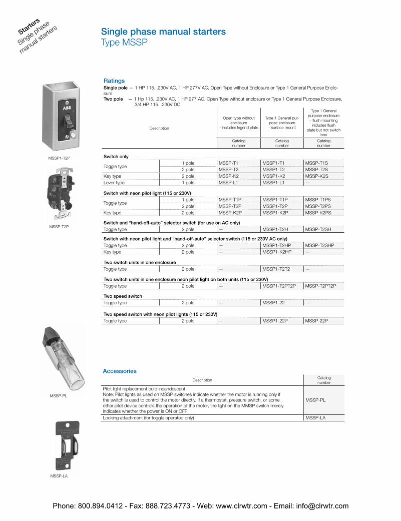
Starters
Single phase
manual starte
rs Single phase manual startersType MSSP
MSSP1-T2P
MSSP-T2P
MSSP-PL
MSSP-LA
RatingsSingle pole — 1 HP 115...230V AC, 1 HP 277V AC, Open Type without Enclosure or Type 1 General Purpose Enclo-sureTwo pole — 1 Hp 115...230V AC, 1 HP 277 AC, Open Type without enclosure or Type 1 General Purpose Enclosure, 3/4 HP 115...230V DC
Description
Open type without enclosure
- includes legend plate
Type 1 General pur-pose enclosure- surface mount
Type 1 General purpose enclosure- flush mounting
includes flushplate but not switch
box
Catalognumber
Catalognumber
Catalognumber
Switch only
Toggle type1 pole MSSP-T1 MSSP1-T1 MSSP-T1S2 pole MSSP-T2 MSSP1-T2 MSSP-T2S
Key type 2 pole MSSP-K2 MSSP1-K2 MSSP-K2SLever type 1 pole MSSP-L1 MSSP1-L1 —
Switch with neon pilot light (115 or 230V)
Toggle type1 pole MSSP-T1P MSSP1-T1P MSSP-T1PS2 pole MSSP-T2P MSSP1-T2P MSSP-T2PS
Key type 2 pole MSSP-K2P MSSP1-K2P MSSP-K2PS
Switch and “hand-off-auto” selector switch (for use on AC only)Toggle type 2 pole — MSSP1-T2H MSSP-T2SH
Switch with neon pilot light and “hand-off-auto” selector switch (115 or 230V AC only)Toggle type 2 pole — MSSP1-T2HP MSSP-T2SHPKey type 2 pole — MSSP1-K2HP —
Two switch units in one enclosureToggle type 2 pole — MSSP1-T2T2 —
Two switch units in one enclosure neon pilot light on both units (115 or 230V)Toggle type 2 pole — MSSP1-T2PT2P MSSP-T2PT2P
Two speed switchToggle type 2 pole — MSSP1-22 —
Two speed switch with neon pilot lights (115 or 230V)Toggle type 2 pole — MSSP1-22P MSSP-22P
AccessoriesDescription
Catalognumber
Pilot light replacement bulb incandescentNote: Pilot lights as used on MSSP switches indicate whether the motor is running only ifthe switch is used to control the motor directly. If a thermostat, pressure switch, or someother pilot device controls the operation of the motor, the light on the MMSP switch merelyindicates whether the power is ON or OFF
MSSP-PL
Locking attachment (for toggle operated only) MSSP-LA
Phone: 800.894.0412 - Fax: 888.723.4773 - Web: www.clrwtr.com - Email: [email protected]
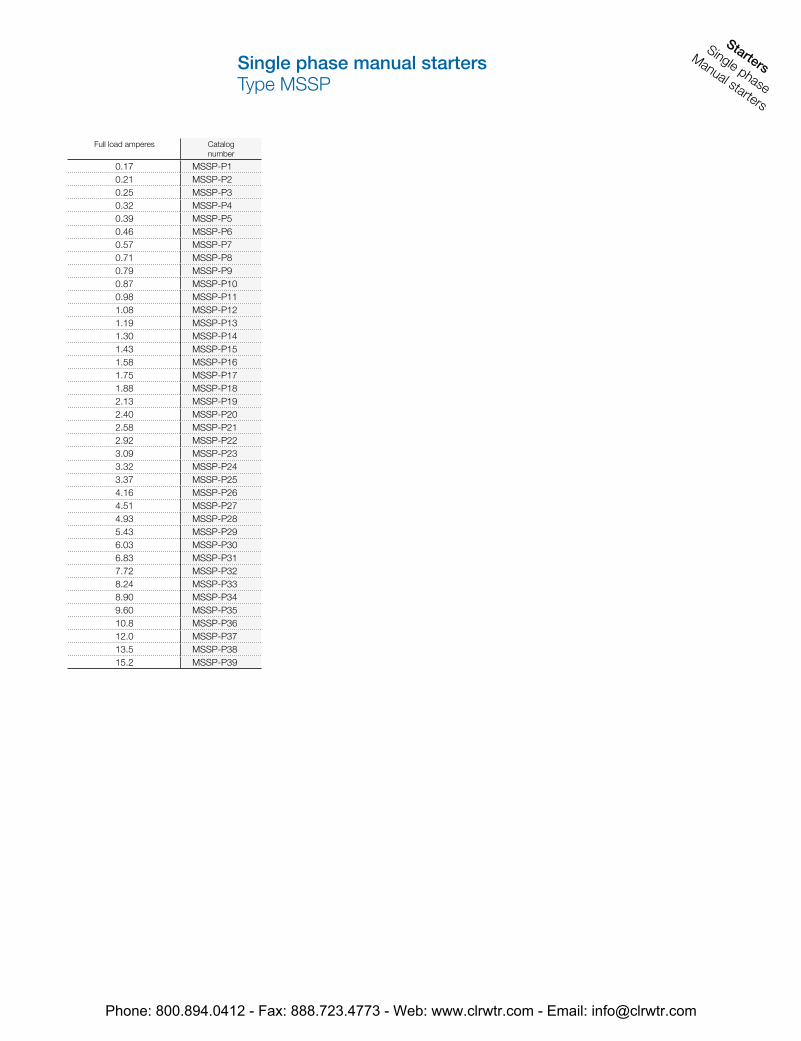
StartersSingle phase
Manual starters
Single phase manual startersType MSSP
Full load amperes Catalognumber
0.17 MSSP-P10.21 MSSP-P20.25 MSSP-P30.32 MSSP-P40.39 MSSP-P50.46 MSSP-P60.57 MSSP-P70.71 MSSP-P80.79 MSSP-P90.87 MSSP-P100.98 MSSP-P111.08 MSSP-P121.19 MSSP-P131.30 MSSP-P141.43 MSSP-P151.58 MSSP-P161.75 MSSP-P171.88 MSSP-P182.13 MSSP-P192.40 MSSP-P202.58 MSSP-P212.92 MSSP-P223.09 MSSP-P233.32 MSSP-P243.37 MSSP-P254.16 MSSP-P264.51 MSSP-P274.93 MSSP-P285.43 MSSP-P296.03 MSSP-P306.83 MSSP-P317.72 MSSP-P328.24 MSSP-P338.90 MSSP-P349.60 MSSP-P3510.8 MSSP-P3612.0 MSSP-P3713.5 MSSP-P3815.2 MSSP-P39
Phone: 800.894.0412 - Fax: 888.723.4773 - Web: www.clrwtr.com - Email: [email protected]
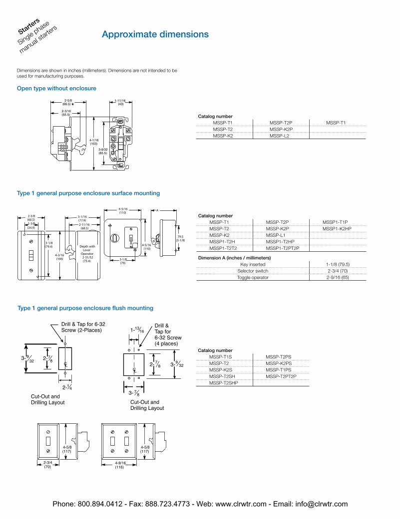
Starters
Single phase
manual starte
rsApproximate dimensions
Dimensions are shown in inches (millimeters). Dimensions are not intended to beused for manufacturing purposes.
Open type without enclosure
Type 1 general purpose enclosure surface mounting
Type 1 general purpose enclosure flush mounting
Catalog numberMSSP-T1 MSSP-T2P MSSP-T1MSSP-T2 MSSP-K2PMSSP-K2 MSSP-L2
Catalog numberMSSP-T1 MSSP-T2P MSSP1-T1PMSSP-T2 MSSP-K2P MSSP1-K2HPMSSP-K2 MSSP-L1MSSP1-T2H MSSP1-T2HPMSSP1-T2T2 MSSP1-T2PT2P
Dimension A (inches / millimeters)Key inserted 1-1/8 (79.5)
Selector switch 2-3/4 (70)Toggle operator 2-9/16 (65)
Catalog numberMSSP-T1S MSSP-T2PSMSSP-T2 MSSP-K2PSMSSP-K2S MSSP-T1PSMSSP-T2SH MSSP-T2PT2PMSSP-T2SHP
Phone: 800.894.0412 - Fax: 888.723.4773 - Web: www.clrwtr.com - Email: [email protected]