abusiness aircraft engine design111
TRANSCRIPT

7/21/2019 Abusiness Aircraft Engine Design111
http://slidepdf.com/reader/full/abusiness-aircraft-engine-design111 1/100
GAS TURBINE

7/21/2019 Abusiness Aircraft Engine Design111
http://slidepdf.com/reader/full/abusiness-aircraft-engine-design111 2/100
Page | 1
Acknowledgment
"It is not possible to prepare this project report without the assistance &
encouragement of other people. This one is certainly no exception."
On the very outset of this report, I would like to extend my sincere & heartfelt
obligation towards all the personages who have helped me in this work. Without
their active guidance, help, cooperation & encouragement, I would not have made
headway in the project. I am ineffably indebted to (supervisor name) for
conscientious guidance and encouragement to accomplish this assignment. I extend
my gratitude to (COLLEGE NAME) for giving me this opportunity. At last but not
least gratitude goes to all of my friends who directly or indirectly helped me to
complete this project report. Any omission in this brief acknowledgement does not
mean lack of gratitude.

7/21/2019 Abusiness Aircraft Engine Design111
http://slidepdf.com/reader/full/abusiness-aircraft-engine-design111 3/100
Page | 2
Declaration
This report was written by (student Name) a student in the (Department Name) at
(University Name). It has not been altered or corrected as a result of assessment and
it may contain errors and omissions. The views expressed in it together with any
recommendations are of the student.

7/21/2019 Abusiness Aircraft Engine Design111
http://slidepdf.com/reader/full/abusiness-aircraft-engine-design111 4/100
Page | 3
Table of Contents
Acknowledgment ................................................................................................................ 1
Declaration .......................................................................................................................... 2
List of figures ...................................................................................................................... 6
Chapter 1 ............................................................................................................................. 9
(Introduction) ...................................................................................................................... 9
1.1 Gas turbine definition ......................................................................................... 10
1.2 Gas turbine types ................................................................................................ 11
The gas turbine can be classified into different types, which listed below. .............. 11
1.2.1Turbojet ............................................................................................................. 11
1.2.2 Turbofan ........................................................................................................... 12
1.2.3 Turboprop ........................................................................................................ 13
1.2.4 Turbo-shaft ....................................................................................................... 13
1.2.5 Industrial gas turbines for power generation ................................................... 14
1.3. Parts of Gas Turbine .............................................................................................. 14
1.3.1 Inlet section ............................................................................................................. 15
1.3.2 Compressor ............................................................................................................. 16
1.3. 3 Combustion system ............................................................................................... 16
1.3.4 Turbine.................................................................................................................... 17
1.3.5 Exhaust system ....................................................................................................... 17
1.3.6 Exhaust diffuser ..................................................................................................... 18
1.4 Open-Cycle and Closed Cycle .............................................................................. 18
1.5 Gas Turbine Design Procedure ............................................................................... 19
Chapter Two...................................................................................................................... 21

7/21/2019 Abusiness Aircraft Engine Design111
http://slidepdf.com/reader/full/abusiness-aircraft-engine-design111 5/100
Page | 4
(Related studies)................................................................................................................ 21
2.1 Introduction ............................................................................................................. 22
2.2 literature review ...................................................................................................... 22
2.2.1 Engine cycle ..................................................................................................... 23
2.2.2 Engine modification ......................................................................................... 25
2.2.3 Gas Turbine Emission ...................................................................................... 29
2.2.4 Combined Cycle............................................................................................... 30
2.2.5 Gas Turbine Troubleshooting Loads and Failure Modes .................................... 32
2.2.6 Gas Turbine Maintenance ................................................................................ 34
2.2.7 Gas Turbine Materials and Blades ................................................................... 35
Chapter Three.................................................................................................................... 39
(Theory of Gas Turbines) .................................................................................................. 39
3.1 Introduction ............................................................................................................. 40
3.2 Operation Principle of the Main Components of the Gas Turbine ......................... 40
3.2.1 Compressor ...................................................................................................... 40
3.2.2 Combustor ........................................................................................................ 44
3.2.3 Turbine ............................................................................................................. 48
3.2.4 Nozzle and Diffuser ......................................................................................... 49
3.3 Gas Turbine and Brayton cycle............................................................................... 51
3.4 payload calculations ............................................................................................... 51
3.5 engine noise ........................................................................................................... 51
CHAPTER FOUR ............................................................................................................. 56
(Engine specifications Selection) ...................................................................................... 56
4.1Engine selection requirements ................................................................................. 56
4.1.1 Engine Requirement......................................................................................... 57

7/21/2019 Abusiness Aircraft Engine Design111
http://slidepdf.com/reader/full/abusiness-aircraft-engine-design111 6/100
Page | 5
4.1.2 Performance parameters................................................................................... 57
4.1.3 Select engine component and materials. .......................................................... 58
4.1.4 Gas turbine limitations ..................................................................................... 63
4.1.4 Performance theoretical analysis ..................................................................... 64
Chapter Five ...................................................................................................................... 65
(Theoretical cycle analysis) .............................................................................................. 65
5.1 Introduction ............................................................................................................. 66
5.2 The gas turbine cycle governing equations ............................................................. 67
5.3Turbojet engine performance calculations ............................................................... 70
Flow velocity and mass flow rate .......................................................................... 70
Compressor ............................................................................................................ 70
Combustion chamber ............................................................................................. 71
Turbine ................................................................................................................... 71
Nozzle .................................................................................................................... 72
Thermal efficiency: ................................................................................................ 72
Thrust calculations ................................................................................................. 72
4.3.1 Discussion of calculations................................................................................ 73
4.4 Discussion of results ............................................................................................... 75
4.4 Performance analysis using Matlab.................................................................... 81
Conclusion ........................................................................................................................ 85
References ......................................................................................................................... 87
Appendix ........................................................................................................................... 91

7/21/2019 Abusiness Aircraft Engine Design111
http://slidepdf.com/reader/full/abusiness-aircraft-engine-design111 7/100
Page | 6
List of figures
Figure 1 energy transformation ......................................................................................... 10
Figure 2 the turbojet engine. Available at ......................................................................... 11
Figure 3 Turbofan gas turbine........................................................................................... 12
Figure 4Turboprop engine ................................................................................................ 13
Figure 5 Turbo-shaft layout, Available at ........................................................................ 14
Figure 6 Gas Turbine Parts. Available at ......................................................................... 15
Figure 7 Compressor Parts. (ACATERPILLAR Company, 2010) .................................. 16
Figure 8 Combustion System. (ACATERPILLAR Company, 2010)............................... 17
Figure 9 Open cycle diagram. (Roco et al., 1997 ............................................................. 18
Figure 10 Closed cycle diagram. (Roco et al., 1997) ........................................................ 19
Figure 11 Processes in P, V diagram. (Soares, 2007) ...................................................... 24
Figure 12 Process in h, S diagram (Soares, 2007) ............................................................ 24
Figure 13 Schematic diagram for heat exchanger. (Langston& Opdyke, 1997) .............. 26
Figure 14 The enthalpy-entropy diagram for intercooling. (Soares, 2007) ...................... 27
Figure 15 Schematic diagram for intercooling processes. (Langston& Opdyke, 1997) ... 27
Figure 16 The enthalpy-entropy diagram for reheating. (Soares, 2007)........................... 28
Figure 17 Schematic diagram for reheating processes. (Langston& Opdyke, 1997). ...... 29
Figure 18: Schematic diagram of the three processes that introduced to gas turbine.
(Brooks, 2000) .................................................................................................................. 31
Figure 19: T-S diagram modification on Brayton cycle. (Brooks, 2000) ......................... 32
Figure 20: Overall definition. (Sorokes et.al , 2006) ....................................................... 34
Figure 21 Temperature and pressure profile in gas turbine. (Carlos, 2007) ..................... 35
Figure 22 Creep rupture lives of alloy A, B and C plotted against the Solution Index
value. ................................................................................................................................. 37
Figure 23 : compressor classification (Mattingly and Ohain, 1996) ................................ 41
Figure 24 operating cost of the compressor (Mattingly and Ohain, 1996) ....................... 43

7/21/2019 Abusiness Aircraft Engine Design111
http://slidepdf.com/reader/full/abusiness-aircraft-engine-design111 8/100
Page | 7
Figure 25: Can type (Lefebvre, 1999). .............................................................................. 44
Figure 26 Cannular type (Lefebvre, 1999). ...................................................................... 45
Figure 27 Annular type (Lefebvre, 1999). ........................................................................ 45
Figure 28 burner component (Lefebvre, 1999). ................................................................ 47
Figure 29 Nozzle (Jiang, 1997) ......................................................................................... 50
Figure 30: Diffuser (Jiang, 1997)...................................................................................... 50
Figure 31: Open cycle (Tanaka et al., 2007) ..................................................................... 52
Figure 32: Closed cycle (Tanaka et.al, 2007) ................................................................... 52
Figure 33 T-S diagram (Tanaka et.al, 2007) ..................................................................... 53
Figure 34 major engine components ................................................................................. 58
Figure 35 The axial flow compressor ............................................................................... 59
Figure 36 combustion chamber ......................................................................................... 60
Figure 37 A twin turbine and shaft arrangement. ............................................................. 62
Figure 38 exhaust system .................................................................................................. 63
Figure 39 the cycle block diagram (DUNN, 2005). .......................................................... 66
Figure 40 The schematic diagram for a simple gas turbine (DUNN, 2005). .................... 67
Figure 41 T-s and P-v diagrams LANE, 2001) ................................................................. 68
Figure 42 The schematic diagram for a Atmospheric Temperature Vs. Altitude ............. 75
Figure 43 Atmospheric Pressure Vs. Altitude .................................................................. 76
Figure 44: Combustion chamber inlet Temperature Vs. Altitude ..................................... 76
Figure 45: Combustion chamber inlet Pressure Vs. Altitude ........................................... 77
Figure 46: Heat addition Vs. Altitude ............................................................................... 78
Figure 47: Heat rejection Vs. Altitude .............................................................................. 78
Figure 48: Power in Vs. Altitude ...................................................................................... 79
Figure 49: Power in Vs. Altitude ...................................................................................... 80
Figure 50 Matlab code ...................................................................................................... 81
Figure 51 the turbine work Vs. the compressor ................................................................ 82
Figure 52 the Wt Vs. ( T2 & T4) ...................................................................................... 83
Figure 53 the network plot Vs.( wt and Wc ) ................................................................... 83
Figure 54 T4 Vs. T2 .......................................................................................................... 84

7/21/2019 Abusiness Aircraft Engine Design111
http://slidepdf.com/reader/full/abusiness-aircraft-engine-design111 9/100
Page | 8
Abstract
Gas turbine engines are an internal combustion engine that provides mechanical power
through using gas as the working fluid. The definition, types, components, operation as
well as performance analysis for this engine was being the main aims that were discussed
in this project. To simply understand the basic concepts associated with this engine, the
project was divided into five chapters, with each of them discussed a specific topic.
The selection for the engine type to be used depends on the type of application at which it
used. In addition to that, there are other requirements that should be taken into account in
selecting the engine which are: the selection of the engine parameters, components,
materials and performance analysis. The performance analyses were developed to select
the engine. It was evaluated mathematically and then by using MATLAB software. The
analysis of the cycle was obtained at different altitude where the power required to
operate the engine is reduced with increasing the height. Also the performance of the
engine was analyzed related to the efficiency of the cycle where the values of the
efficiency were taken from 0.6-1 using MATLAB.
The selected engine was a turbojet engine. The principle of work for the turbojet engine
is to extract the fuel chemical energy and convert it to mechanical work through using the
gaseous energy of gas to drive both the engine and the propeller, which is then propelling
the airplane. The operation of this engine can be summarized as “the gas flows
continuously and entered a compressor at where it will be compressed and then heated in
the combustion chamber, and lastly, the heated gas flows through the turbine which
converts the gas energy into mechanical work.
From the theoretical analysis, this engine has an efficiency of 66 %, this means that it
produced a high power due to the direct correlation between output power and engine
efficiency. As a result, when less fuel is consumed through the engine and when the
output power is more, the engine will be more efficient.

7/21/2019 Abusiness Aircraft Engine Design111
http://slidepdf.com/reader/full/abusiness-aircraft-engine-design111 10/100
Page | 9
Chapter 1
(Introduction)

7/21/2019 Abusiness Aircraft Engine Design111
http://slidepdf.com/reader/full/abusiness-aircraft-engine-design111 11/100
Page | 10
1.1 Gas turbine definition
Gas turbine is a mechanical machine transformed energy from chemical to thermal and
then to mechanical as shown in Figure.1. In gas turbines is a constant flow of the liquid
agent. At first this fluid is compressed in the compressor then heated in the combustion
chamber. Finally, it passes through the turbine to convert the stored energy in gas to
mechanical work (Kulikov & Thompson, 2004).
Figure 1 energy transformation
Gas turbines have great roles in the electricity generation during the past years. Because
they have low investment cost, the gas turbines can be implemented to supply the power
for the transmission lines, and also they have considerable roles during the emergency
statues. Different researches have done focuses on the estimation of the performance of
gas turbines; these studies are divided into two main classes. The first one involves
studies have focused on the modeling of gas turbine cycle’s parts, the second type of
researches have focused on the most important parameters effecting on the design
performance (Lane. D, 2010).
chemical
energy
thermal
energy
mechanical
energy

7/21/2019 Abusiness Aircraft Engine Design111
http://slidepdf.com/reader/full/abusiness-aircraft-engine-design111 12/100
Page | 11
1.2 Gas turbine types
The gas turbine can be classified into different types, which listed below.
1.2.1Turbojet
Turbojet is an earliest and simplest kind of gas turbine; this type is usually used within
high speed aircraft Figure.2 shows the main parts of turbojet engine
Figure 2 the turbojet engine. Available at
http://wings.avkids.com/Book/Propulsion/advanced/types-01.html (accessed in 24 Jan 2012)
These turbines have different advantages such as- high jet velocity and small frontal area,
also the turbojet extracts the energy from the gas stream in order to drive the compressor
(Liu, F., 2001).

7/21/2019 Abusiness Aircraft Engine Design111
http://slidepdf.com/reader/full/abusiness-aircraft-engine-design111 13/100
Page | 12
1.2.2 Turbofan
This type is the widest type used for the aircraft propulsion Figure.3 shows the
main parts of this type. The air enters the engine and then is compressed and passedto the combustion chamber, part of air in this type is compressed to the lesser
extent, and bypasses the combustion section as shown in Figure .3, this method will
help to cool the thrust also the bypass air will rejoin the hot gases downstream of the
turbofan. In these cases, the overall velocity of the jet will be reduced in order get
lower noise levels, better efficiency and improved ( SFC) Specific Fuel
Consumption.( Roux,E., 2007).
Figure 3 Turbofan gas turbine.
Available at : http://www.techberth.com/high-bypass-ratio-turbofan-engine-components/(accessed at 24
Jan 2012)

7/21/2019 Abusiness Aircraft Engine Design111
http://slidepdf.com/reader/full/abusiness-aircraft-engine-design111 14/100

7/21/2019 Abusiness Aircraft Engine Design111
http://slidepdf.com/reader/full/abusiness-aircraft-engine-design111 15/100
Page | 14
Figure 5 Turbo-shaft layout, Available at
http://www.britannica.com/EBchecked/media/19425/Turboshaft-engine-driving-a-helicopter-rotor-as-propulsor
accessed in 25 Jan 2012)
1.2.5 Industrial gas turbines for power generation
Industrial gas turbine has differ construction than other types where the size is various
from small to enormous size. The efficiency of this type can achieve 60% when remains
energy from the gas turbine is used again by a heat recovery to power in steam turbine
during the combined cycle configuration. This type is used generally to produce
electricity the following section will show the parts of this type in details:
1.3. Parts of Gas Turbine
Gas turbine consist of four main parts (compressor, injector, turbine and exhaust system)
figure 6 show them and other component.

7/21/2019 Abusiness Aircraft Engine Design111
http://slidepdf.com/reader/full/abusiness-aircraft-engine-design111 16/100

7/21/2019 Abusiness Aircraft Engine Design111
http://slidepdf.com/reader/full/abusiness-aircraft-engine-design111 17/100
Page | 16
1.3.2 Compressor
Compressors are responsible for getting all the need from gas turbine. In addition to the
amount of compressed air must be fixed and high. Compression ratio ranging from about
9.5:1.
Compressor consists of several stages at each stage gradually increase the pressure for the
previous phase. Each stage contains of a multi of rotors which connected to a rotating
disk, which is followed by pro vanes connected to a fixed ring. And it also includes two
guides’ vanes the inlet and outlet. However vanes, is installed at the inlet and outlet
compressor. As shown in Figure 7
Figure 7 Compressor Parts. (ACATERPILLAR Company, 2010)
1.3. 3 Combustion system
It also known as Burner which provides heat to hot and pressurized gas, the main part in
the combustion system is Injector. The large amounts of fuel and air are difficult to
control. Which must accomplished with minimal loss pressure and the maximum heat
release. As shown in figure 8. (ACATERPILLAR Company, 2010)

7/21/2019 Abusiness Aircraft Engine Design111
http://slidepdf.com/reader/full/abusiness-aircraft-engine-design111 18/100
Page | 17
Figure 8 Combustion System. (ACATERPILLAR Company, 2010)
:
1.3.4 Turbine
Covert the high pressure and temperature to mechanical energy using a set of stationary
vanes connected by a set of rotating blades that worked under the reverse of thecompressor. The velocity of gas turbine increased related to the temperature and pressure
which increases the power can be extracted from the turbine.
1.3.5 Exhaust system
After the gas passes the turbine, then discharged to the exhaust the thermal energy is
extracted from the gas to be mechanical energy , the remains energy in gases can be used
again to enhance the performance of the gas turbine where these gases can be used in
regenerative unit. (Kulikov& Thompson, 2004)

7/21/2019 Abusiness Aircraft Engine Design111
http://slidepdf.com/reader/full/abusiness-aircraft-engine-design111 19/100

7/21/2019 Abusiness Aircraft Engine Design111
http://slidepdf.com/reader/full/abusiness-aircraft-engine-design111 20/100
Page | 19
Figure 10 Closed cycle diagram. (Roco et al., 1997)
1.5 Gas Turbine Design Procedure
Different researches have done focuses on the estimation of the performance of gas
turbines; these studies are divided into two main classes. The first one involves studies
have focused on the modeling of gas turbine cycle’s parts, the second type of researches
have focused on the most important parameters effecting on the design performance.
The most important factors will be studied in this project are: the cycle efficiency
(turbine, compressor), the power output, and the temperature and pressure at each state.
Advancements in materials used for manufacturing gas turbine which operate on high
temperatures and pressures have contributed during the enhancement of the temperature
capabilities and efficiencies of the gas turbines.. Finite element analysis involves of a
computer model of a material of any mechanical design that is subjected under stress in
order to get specific results.

7/21/2019 Abusiness Aircraft Engine Design111
http://slidepdf.com/reader/full/abusiness-aircraft-engine-design111 21/100
Page | 20
To design a gas turbine there are many steps are mention below:
1- Calculate the needed power for gas turbine.
2-Take the geographical factors in deigns account.
3- Select the operation cycle of gas turbine.
4- Make all calculation to find the variables of all point in the operation cycle.
5- Select the optimum part according to design calculation. (Strand, 2006).

7/21/2019 Abusiness Aircraft Engine Design111
http://slidepdf.com/reader/full/abusiness-aircraft-engine-design111 22/100
Page | 21
Chapter Two
(Related studies)

7/21/2019 Abusiness Aircraft Engine Design111
http://slidepdf.com/reader/full/abusiness-aircraft-engine-design111 23/100
Page | 22
2.1 Introduction
This chapter will discuss a literature review for the previous works related to the gas
turbine. the literature includes a discussion for the ideal operation cycle of the gas
turbine (Brayton), discuss its calculation like (performing, efficiency and pressure ratio)
and all possible modification to enhance it efficiency which can be applied on the
Brayton cycle such as (heat exchanger, inter cooling, reheat and combination between
them).
2.2 literature review
According to (TSA, 2004) research about design and performance requirement for a
“Gas-Turbine Engine from an Automobile Turbocharger”, and as a result defining the gas
turbine as systems produce a positive work transfer by using air and fuel so it considered
as thermodynamic systems converting the chemical energy in fuel to mechanical energy.
The gas turbine activates on an unlock cycle consisting of a combustor, a compressor,
and a turbine collective in series. Atmospheric air goes through the compressor to be
compressed by “a negative shaft work transfer” to be combined and burned in the
combustion chamber with fuel. Both the specific volume of the air and the temperature
increases in the combustor. Then the hot air is fed into to be expanded in the turbine. The
air expansion generates “a positive shaft work transfer”, finally, exhausting the expanded
air to the atmosphere. A positive shaft work transfer is created since the negative shaft
work transfer created by the turbine need to operate the compressor is lower than the
positive work transfer.
(Roberts, 1990) was worked on one type of gas turbine, which is the turbofan engine. He
defined it as an “engine where the first stage compressor rotor is larger in diameter than
the rest of the engine” (Airplane…, n.d, pg.3). In the turbofan engine the air passesthrough the fan that is situated near the inner diameter the same air also passes through
the compressor stages situated in the core of the engine and then it is furthermore
processed and compressed through the engine cycle (Airplane…, n.d.pg.5). He said, to
design Turbo fan engine there is a need of wave rotor which is stated to be the partial
admission device that causes the one gas to compress another through the use of wave

7/21/2019 Abusiness Aircraft Engine Design111
http://slidepdf.com/reader/full/abusiness-aircraft-engine-design111 24/100
Page | 23
propagation. The development of these devices for Turbo fan engines were designed in
the early 1950s as stated by Roberts in his Thesis. Further on, there were few
developments which were stated to be attempted after the 1960’s. It is also stated that the
Wave rotor components have promising applications in small engines that range from
600 to 1000 in pounds thrust range. Such kind of engines are stated to have applications
which are used in cruise missile, piloted vehicles, helicopters and the small thrust
turbofans (Roberts, 1990).
2.2.1 Engine cycle
Soares, 2007) was studied the ideal cycle for gas turbine engine which is called aBrayton. This theoretical cycle for simple gas turbine consists of two isentropic and two
constant pressure processes. The compressor consists of four main parts:
Inlet duct
Compressor
Fuel injector
Exhaust diffuser.
In every inlet and outlet of the compressor parts Joule-Brayton define some variables
such as temperature (T), pressure (P), entropy (S), enthalpy (h) and volume (V) can be
used to study the compressor, as shown in figure 11 and 12.

7/21/2019 Abusiness Aircraft Engine Design111
http://slidepdf.com/reader/full/abusiness-aircraft-engine-design111 25/100
Page | 24
Figure 11 Processes in P, V diagram. (Soares, 2007)
Figure 12 Process in h, S diagram (Soares, 2007)
From the relationships have been drawn in figures (11 and 12), it was concluding that:
- During step 2------- 3 the input power to compressor given as:
)

7/21/2019 Abusiness Aircraft Engine Design111
http://slidepdf.com/reader/full/abusiness-aircraft-engine-design111 26/100

7/21/2019 Abusiness Aircraft Engine Design111
http://slidepdf.com/reader/full/abusiness-aircraft-engine-design111 27/100

7/21/2019 Abusiness Aircraft Engine Design111
http://slidepdf.com/reader/full/abusiness-aircraft-engine-design111 28/100

7/21/2019 Abusiness Aircraft Engine Design111
http://slidepdf.com/reader/full/abusiness-aircraft-engine-design111 29/100
Page | 28
Reheating
The main idea of reheating is similar to intercooling but it applied in the turbine at point
4 which lead to increase the output work as shown in figure below.
Figure 16 The enthalpy-entropy diagram for reheating. (Soares, 2007)
The output work given as.
W output= W4−4.5 +W4.5−5 = C p (T4− T4.5) + C p (T4.5 − T5).
Figure 17 below show the schematic diagram for reheating processes.

7/21/2019 Abusiness Aircraft Engine Design111
http://slidepdf.com/reader/full/abusiness-aircraft-engine-design111 30/100

7/21/2019 Abusiness Aircraft Engine Design111
http://slidepdf.com/reader/full/abusiness-aircraft-engine-design111 31/100
Page | 30
As a result of existing HRSG’s in the com pound cycle which makes it ideal for medium
load application. The HRSG’s same as SCR in the NOx control.
The emission percentage in the compound cycle depends on the hourly limitation and
Ton per Year (TPY) produced.
2.2.4 Combined Cycle
The thermal efficiency of a gas turbine can be increased by decreasing the input power or
increasing the output work or both.to reduce the input work the required ratio pressure
must be smallest as possible and the compression done in multi stage with intercooling.
To enhance the output work the required ratio pressure must be larger as possible, the
expansion process done in multi stage with reheating. (Brooks, 2000)
Two previous processes must do without raising the maximum temperature in the cycle
that leads to increase the number of stages of the cycle.
During the combustion process in the gas turbine a heat exchanger introduced between
the gases leave the turbine (high temperature) and the gases leaves the compressor (low
temperature) to increase the thermal efficiency of the cycle. Figure 18 shows the
schematic diagram of the three processes that introduced to gas turbine.

7/21/2019 Abusiness Aircraft Engine Design111
http://slidepdf.com/reader/full/abusiness-aircraft-engine-design111 32/100
Page | 31
Figure 18: Schematic diagram of the three processes that introduced to gas turbine. (Brooks, 2000)
Figure 19 show the modification occurs in the T-S diagram on the gas turbine.

7/21/2019 Abusiness Aircraft Engine Design111
http://slidepdf.com/reader/full/abusiness-aircraft-engine-design111 33/100
Page | 32
Figure 19: T-S diagram modification on Brayton cycle. (Brooks, 2000)
2.2.5 Gas Turbine Troubleshooting Loads and Failure Modes
The failure of gas turbine occurs due to many reasons like: loss of performance,
excessive noise, vibration, poor engine control, structural failure, excessive exhaust
emission and over load.
The structural failure of gas turbine can be defined as any change in the shape, size, or
mechanical properties lead to make the part unsatisfied to do it work.
On the other hand, can be define as any physical or chimerical change lead to make the
part unsatisfied to do it work. (Stelling & MNIMH, 2010)
Vibration is one of the most important issue must be consider due to it effect, as known
compressor and turbine blades are subjected to High Cycle Fatigue (HCF) its connected

7/21/2019 Abusiness Aircraft Engine Design111
http://slidepdf.com/reader/full/abusiness-aircraft-engine-design111 34/100

7/21/2019 Abusiness Aircraft Engine Design111
http://slidepdf.com/reader/full/abusiness-aircraft-engine-design111 35/100

7/21/2019 Abusiness Aircraft Engine Design111
http://slidepdf.com/reader/full/abusiness-aircraft-engine-design111 36/100
Page | 35
Actually for every 25000 to 50000 operation work hour gas turbine needs an overhaul
(dimensional inspection, testing and product upgrade) depending on load and type of
maintenance. (Energy Nexus Group, 2002)
2.2.7 Gas Turbine Materials and Blades
As a result of little operation hour of the gas turbine due to high pressure and temperature
which a result of the material used, unacceptable reliability and thermodynamic
efficiency, damaging to equipment and injures to people, all these reason make the
material used as an important factor in the design process of gas turbine.(Carlos, 2007)
Compression, combustion, generation power and exhaust processes occurs in gas turbine
the most dangerous point located between the combustion chamber outlet and the turbine
inlet, it is the most sensible and challenging design point. Look at figure 21.
Figure 21 Temperature and pressure profile in gas turbine. (Carlos, 2007)

7/21/2019 Abusiness Aircraft Engine Design111
http://slidepdf.com/reader/full/abusiness-aircraft-engine-design111 37/100

7/21/2019 Abusiness Aircraft Engine Design111
http://slidepdf.com/reader/full/abusiness-aircraft-engine-design111 38/100

7/21/2019 Abusiness Aircraft Engine Design111
http://slidepdf.com/reader/full/abusiness-aircraft-engine-design111 39/100

7/21/2019 Abusiness Aircraft Engine Design111
http://slidepdf.com/reader/full/abusiness-aircraft-engine-design111 40/100
7/21/2019 Abusiness Aircraft Engine Design111
http://slidepdf.com/reader/full/abusiness-aircraft-engine-design111 41/100
Page | 40
3.1 Introduction
This chapter will discuss the operation principle of the main parts of the gas turbine
system (compressor, combustor, turbine and nozzle and diffuser), and the possible failure
modes for each component in the gas turbine system. Then discussion will be carried for
how to use the gas turbine in distillation process and what is the possibility and
affectivity of the distillation in the gas turbine power plant. Moreover, the efficiency of
the gas turbine will be discussed according to the Brayton cycle; finally the main
differences between the steam turbine and the gas turbine will be mentioned.
3.2 Operation Principle of the Main Components of the Gas Turbine
Gas turbine is one of the engineering applications which have a wide range uses in the
industrial applications; the gas turbine consists of four main components which are:
1- Compressor
2- Combustor
3- Turbine
4- Nozzle and Diffuser (Mattingly and Ohain, 1996)
3.2.1 Compressor
Compressor in different applications is used to improve the overall efficiency of the
system. The compressor in general consists of many parts, which are (Mattingly and
Ohain, 1996):
Intake Air Filters: this part prevent any dust from entering into the compressor
Cooler stage: in this stage the temperature of the inlet air will be reduced to
decrease the compression ratio and enhance the compressor efficiency.
Impeller: it makes the compression in the stage of the compressor.

7/21/2019 Abusiness Aircraft Engine Design111
http://slidepdf.com/reader/full/abusiness-aircraft-engine-design111 42/100
Page | 41
COMPRESSORS TYPES
Figure 23 shows the main classification of the compressor based on the principle of
operation and type of forces.
Figure 23 : compressor classification (Mattingly and Ohain, 1996)
The actual volumetric flow rate of the compressor can be calculated form the following
equation:
Where

7/21/2019 Abusiness Aircraft Engine Design111
http://slidepdf.com/reader/full/abusiness-aircraft-engine-design111 43/100

7/21/2019 Abusiness Aircraft Engine Design111
http://slidepdf.com/reader/full/abusiness-aircraft-engine-design111 44/100
Page | 43
Figure 24 operating cost of the compressor (Mattingly and Ohain, 1996)
There are many problems occur in the gas turbines which are:
1- Fouling: is one of the most important problems which can be presented as a result from
the particle in the intake air (smoke, carbon, sea salt and the oil mists) or from the
annulus surface, these particles have a range from 2 to 10 μm which can cause a
change in the airfoil shape, so it is important to make sure there are a good filter in the
first stage in the compressor to avoid this problem and must be optimum for particle
remove, cost, service life and the pressure losses (Mattingly and Ohain, 1996).
2- Hot corrosion: this can be defined as a chemical reaction between a specific material
and the compressor components; this reaction can make a big change in the flow path,
crack or damage in the impeller. The oxidization process become more active under a
high temperature, so the compressor component must be protected from the oxidization
process by coating the component (Mattingly and Ohain, 1996).

7/21/2019 Abusiness Aircraft Engine Design111
http://slidepdf.com/reader/full/abusiness-aircraft-engine-design111 45/100

7/21/2019 Abusiness Aircraft Engine Design111
http://slidepdf.com/reader/full/abusiness-aircraft-engine-design111 46/100
Page | 45
2- Cannular type which shown in figure 26
Figure 26 Cannular type (Lefebvre, 1999).
3- Annular type which shown in figure 27
Figure 27 Annular type (Lefebvre, 1999).

7/21/2019 Abusiness Aircraft Engine Design111
http://slidepdf.com/reader/full/abusiness-aircraft-engine-design111 47/100

7/21/2019 Abusiness Aircraft Engine Design111
http://slidepdf.com/reader/full/abusiness-aircraft-engine-design111 48/100
Page | 47
This process is used in the application which needs a high pressure ratio but in this
method the specification of the fluid must be taken in the considerations and additional
requirements to reach the wanted pressure.
c- Pre-evaporating
In this method the fuel evaporates before enter the combustion zone (Lefebvre, 1999).
d- Vaporizing
The operation principle of this method is same as the operational principle of the air blast
but in this method the surrounding heat is used to improve the evaporation process.
7- Igniter
It can be defined as a device which gives the spark (to start the combustion) in the
combustion zone, the electrical spark is usually used in different applications but one of
the other important types is the oxygen injection which makes the combustion process
easier.
The burner and its main component can be shown in figure 28.
Figure 28 burner component (Lefebvre, 1999).

7/21/2019 Abusiness Aircraft Engine Design111
http://slidepdf.com/reader/full/abusiness-aircraft-engine-design111 49/100

7/21/2019 Abusiness Aircraft Engine Design111
http://slidepdf.com/reader/full/abusiness-aircraft-engine-design111 50/100

7/21/2019 Abusiness Aircraft Engine Design111
http://slidepdf.com/reader/full/abusiness-aircraft-engine-design111 51/100

7/21/2019 Abusiness Aircraft Engine Design111
http://slidepdf.com/reader/full/abusiness-aircraft-engine-design111 52/100

7/21/2019 Abusiness Aircraft Engine Design111
http://slidepdf.com/reader/full/abusiness-aircraft-engine-design111 53/100

7/21/2019 Abusiness Aircraft Engine Design111
http://slidepdf.com/reader/full/abusiness-aircraft-engine-design111 54/100
Page | 53
The process of the closed cycle type in the Brayton can be drawn in the Temperature-
Entropy relationship as shown in figure 33.
Figure 33 T-S diagram (Tanaka et.al, 2007)
From figure 33, it can be shown that the compressor and turbine work at isentropic
process, heat addition and rejection work at constant pressure.

7/21/2019 Abusiness Aircraft Engine Design111
http://slidepdf.com/reader/full/abusiness-aircraft-engine-design111 55/100

7/21/2019 Abusiness Aircraft Engine Design111
http://slidepdf.com/reader/full/abusiness-aircraft-engine-design111 56/100
Page | 55
3.5 Aircraft Noisy
Aircraft noise represents a type of pollution called noise pollution, which is generated
mainly due to two reasons; the first is the intake, exhaust and other major engine
components and the aerodynamic drag of air flow around the aircraft body and wings.
Commonly, during the take-offs the noise is generated by the engine. But the airframe
noise is the most important factor during landing, where the engine operates at low
power. The developments and improvement in the manufacturing of the aircraft are
concentrated on enhancing engine and airframe design with an n important aim of
reducing the noise that affects on the aircraft. (CAIRNS PORT AUTHORITY, 2006).
Researchers reach that dying by a heart attack was more public among people with
increased experience to aircraft noise. Those effects was specifically obvious for people
who were exposed to really high levels of noise, and was dependent on how long those
people had lived in the noisy place ( Matthias Egger) . But this study could support to
determine whether the sound is really the main effect, or if it is something else grouped
with the noise, such as air pollution. It's been a problem that when you study the case of
road traffic noise there are both high levels of noise and high level of air pollution. After
taking consideration for the air pollution and other factors including education and
revenue levels, the group found that both the level and duration of aircraft noise increase
the risk of a fatal heart attack (Alleyne, 2010).
Therefore, in the design the turbojet engine is selected since it has the least noise also has
a good performance.

7/21/2019 Abusiness Aircraft Engine Design111
http://slidepdf.com/reader/full/abusiness-aircraft-engine-design111 57/100
Page | 56
CHAPTER FOUR
(Engine specifications Selection)
4.1Engine selection requirements
The gas turbine engine is considered to be a complex machine including operation at
extremes of pressure and temperature and demanding expertise at the highest level of
engineering technology. To select the best engine to use it in any application, some
engine selection requirements should be considered as shown in the following.

7/21/2019 Abusiness Aircraft Engine Design111
http://slidepdf.com/reader/full/abusiness-aircraft-engine-design111 58/100

7/21/2019 Abusiness Aircraft Engine Design111
http://slidepdf.com/reader/full/abusiness-aircraft-engine-design111 59/100

7/21/2019 Abusiness Aircraft Engine Design111
http://slidepdf.com/reader/full/abusiness-aircraft-engine-design111 60/100
Page | 59
run successfully at speeds value below the design condition. As increasing the
pressure ratio, the integration of variable stator vanes makes sure that the airflow
is moved toward the successive stage of “rotor blades” at an suitable angle. Figure
below demonstrates the the axial flow compressor (Rolls-Royce plc company.
2001)
Figure 35 The axial flow compressor
Compressor materials
To select the best material for compressor design, the material should attain the
most cost effective design. For casing designs it requires to build with a light rigid
construction which allows blade tip permissions to be maintained accurately with
a high efficiency. It is generally made from aluminum at the front of the
compression system and at the final stages of the compression system is made
from nickel based alloys (Rolls-Royce plc company. 2001).
b. Combustion chambers

7/21/2019 Abusiness Aircraft Engine Design111
http://slidepdf.com/reader/full/abusiness-aircraft-engine-design111 61/100

7/21/2019 Abusiness Aircraft Engine Design111
http://slidepdf.com/reader/full/abusiness-aircraft-engine-design111 62/100

7/21/2019 Abusiness Aircraft Engine Design111
http://slidepdf.com/reader/full/abusiness-aircraft-engine-design111 63/100
Page | 62
Figure 37 A twin turbine and shaft arrangement.
Turbine MATERIALS
Basically, turbine parts consist of combustion discharge nozzles, the nozzle guide vanes,
turbine discs and the turbine blades.
The Nozzle guide vanes are made from nickel alloy which has a good heat resistance and
Ceramic coatings are used to improve the heat resisting properties and decrease the
quantity of cooling air needed, and thus enhancing the engine efficiency. As well as the
turbine blades are made from Ceramic (Rolls-Royce plc company. 2001).
d. Exhaust system
The main function of the exhaust system of the gas turbine is to pass the discharge gases
of the turbine to atmosphere in the wanted direction to give the resultant thrust. In turbo-
jet engine the pressure and velocity of the exhaust gases generate thrust. The exhaust
system should be designs accurately due to that it has an considerable impact on the
engine performance. The jet pipe and outlet nozzle areas affect the inlet temperature,

7/21/2019 Abusiness Aircraft Engine Design111
http://slidepdf.com/reader/full/abusiness-aircraft-engine-design111 64/100

7/21/2019 Abusiness Aircraft Engine Design111
http://slidepdf.com/reader/full/abusiness-aircraft-engine-design111 65/100

7/21/2019 Abusiness Aircraft Engine Design111
http://slidepdf.com/reader/full/abusiness-aircraft-engine-design111 66/100
Page | 65
Chapter Five
(Theoretical cycle analysis)

7/21/2019 Abusiness Aircraft Engine Design111
http://slidepdf.com/reader/full/abusiness-aircraft-engine-design111 67/100
Page | 66
5.1 Introduction
The basic and ideal cycle is called the constant pressure cycle due to that the cooling and
heating processes are conducted at constant pressure. Figures (34 and 35) below
demonstrates the cycle block diagram and the cycle schematic diagram respectively. The
basic gas turbine cycle is called the Brayton cycle according to George Brayton (LANE,
2001).
Figure 39 the cycle block diagram (DUNN, 2005).

7/21/2019 Abusiness Aircraft Engine Design111
http://slidepdf.com/reader/full/abusiness-aircraft-engine-design111 68/100
Page | 67
Figure 40 The schematic diagram for a simple gas turbine (DUNN, 2005).
5.2 The gas turbine cycle governing equations
There are four ideal processes in the cycle that are (DUNN, 2005):
- Process (1-2) is reversible adiabatic (isentropic) compression (in compressor)
requiring power input.
- Process (2-3) is constant pressure requiring heating addition.
- Process (3-4) is a reversible adiabatic (isentropic) expansion (in turbine)
producing power output.

7/21/2019 Abusiness Aircraft Engine Design111
http://slidepdf.com/reader/full/abusiness-aircraft-engine-design111 69/100
Page | 68
- Process ( 4-1) is a constant pressure cooling requiring heat rejection.
Figure below demonstrates the T-s and P-V diagrams for the brayton cycle.
Figure 41 T-s and P-v diagrams LANE, 2001)
- Efficiency calculations
The thermal efficiency is calculated through applying “the first law of thermodynamic”
which gives:

7/21/2019 Abusiness Aircraft Engine Design111
http://slidepdf.com/reader/full/abusiness-aircraft-engine-design111 70/100

7/21/2019 Abusiness Aircraft Engine Design111
http://slidepdf.com/reader/full/abusiness-aircraft-engine-design111 71/100
Page | 70
5.3Turbojet engine performance calculations
The turbojet engine performance calculations are carried out for private passengers plan
that carrying 30 passenger. The calculation where made when the plane was at 35000 ft
height. At this elevation the initial conditions for temperature and pressure are given
according to (U.S Standard Atmosphere):
- T1= -65.61°C = 218.8K
- P1= 23. 8 KPa
Flow velocity and mass flow rate
Where, R is the gas constant.
√
Assume, A= 0.05 = 0.00464515 based on literature of (CARETTO, 2008), then
Compressor
According to the jet engine literature (*) the Compressors can achieve compression ratios
in excess of 40:1, then assume it to be 45
()

7/21/2019 Abusiness Aircraft Engine Design111
http://slidepdf.com/reader/full/abusiness-aircraft-engine-design111 72/100

7/21/2019 Abusiness Aircraft Engine Design111
http://slidepdf.com/reader/full/abusiness-aircraft-engine-design111 73/100
Page | 72
Nozzle
Thermal efficiency:
Thrust calculations
For a turbojet the thrust equation is given by the general thrust equation (F) with the
pressure-area term set to zero (MARZOCCA, 2011),
To determine the exit velocity, the Mach number at exit should be evaluated as shown
below:
√

7/21/2019 Abusiness Aircraft Engine Design111
http://slidepdf.com/reader/full/abusiness-aircraft-engine-design111 74/100
Page | 73
According the conservation of mass principle then:
4.3.1 Discussion of calculations
The calculations made for the turbojet engine performance in the case of a plane with 30
passengers at a height of 35000 ft. To begin the analysis the initial conditions of the
compressor inlet needed to be determined, and it is determined according to the (U.S
Standard Atmosphere), then the speed of sound is calculated to evaluate the amount of air
entered to the compressor, by knowing the pressure ratio for the compressor the outlet
temperature of the air at the compressor exit, which is increase because of the
compression process, finally the power needed for the compressor is calculated which is
not significant compared to the output power from the turbine .
In combustion chamber, the combustion process represent heat addition to complete the
cycle occurs under condition of constant pressure, and the amount of heat added is
evaluated. This heat added represent a cost must be added to the system, as this heat
added decreases the system will be more efficient and preferable by assuring that the
performance has to be.
In the turbine the expansion process occurs under reversible adiabatic (isentropic)
condition to produce the output power the outlet temperature of the air and the pressure
of the air reduced significantly because of power extraction. The output power is not
significant compared to the input.

7/21/2019 Abusiness Aircraft Engine Design111
http://slidepdf.com/reader/full/abusiness-aircraft-engine-design111 75/100
Page | 74
The Nozzle is a device used to accelerate the fluid before it’s enter the compressor , while
the fluid velocity, it's temperature will be increase but it's pressure will decrease and this
represent a heat rejected in the turbojet system, and this is not a significant value.
Thrust is the force which moves an aircraft through the air; it is used to overcome the
drag of an airplane, and to overcome the weight of a rocket, thrust is generated by the
engines of the aircraft through some kind of propulsion system. The thrust is calculated
using a special equation that depends on the velocities at the inlet and exit of the engine.
Finally, the thermal efficiency is a measure of the performance of the device that uses
thermal energy and calculated by evaluate the net output power by subtract the input
power from the output power, and evaluate the heat added to the system. For this system
the thermal efficiency reaches up to 66 % which is a good percentage that demonstrate
the system performance to use the thermal energy.

7/21/2019 Abusiness Aircraft Engine Design111
http://slidepdf.com/reader/full/abusiness-aircraft-engine-design111 76/100

7/21/2019 Abusiness Aircraft Engine Design111
http://slidepdf.com/reader/full/abusiness-aircraft-engine-design111 77/100
Page | 76
.
Figure 43 Atmospheric Pressure Vs. Altitude
These changes effect on the properties of the inlet air for the engine, so these changes
effect on the compressor efficiency.
2. Pressure and temperature variation in combustion chamber inlet
The figure below shows the variation in the inlet temperature for the combustion chamber
with altitude, where the graph demonstrates that as the altitude increases the inlet
temperature for the combustion chamber decrease. Therefore, the power input to the
compressor will also decrease.
Figure 44: Combustion chamber inlet Temperature Vs. Altitude
0
10
20
30
4050
60
70
80
0 10000 20000 30000 40000
A t m .
P r e s s u r e
( K p a )
Altitude (ft)
Atmospheric Pressure Vs. Altitude
P1(kpa)
0
200
400
600
800
1000
0 10000 20000 30000 40000
I n l e t c o m b u s t i o n c h a m b e r t e m p e r a t u r e
Altitude (ft)
Combustion chamber inlet Temperature Vs.
Altitude
T2

7/21/2019 Abusiness Aircraft Engine Design111
http://slidepdf.com/reader/full/abusiness-aircraft-engine-design111 78/100
7/21/2019 Abusiness Aircraft Engine Design111
http://slidepdf.com/reader/full/abusiness-aircraft-engine-design111 79/100
Page | 78
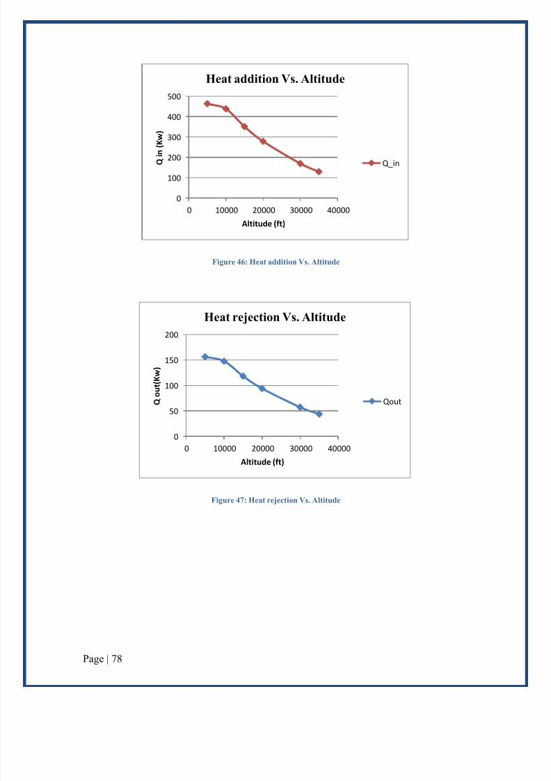
Figure 46: Heat addition Vs. Altitude
Figure 47: Heat rejection Vs. Altitude
0
100
200
300
400
500
0 10000 20000 30000 40000
Q i n ( K w
)
Altitude (ft)
Heat addition Vs. Altitude
Q_in
0
50
100
150
200
0 10000 20000 30000 40000
Q o u t ( K w )
Altitude (ft)
Heat rejection Vs. Altitude
Qout

7/21/2019 Abusiness Aircraft Engine Design111
http://slidepdf.com/reader/full/abusiness-aircraft-engine-design111 80/100
Page | 79
4. Power variation with altitude
The figure below shows the variation in the power input to the compressor with altitude,
where the graph demonstrates that as the altitude increases the input power decreases
linearly. Therefore, this will enhance the performance of the turbo jet since it consumes a
less amount of power, and then the efficiency will also enhanced.
Figure 48: Power in Vs. Altitude
The figure below shows the variation in the power output from the turbine with altitude,
where the graph demonstrates that as the altitude increases the output power decreases in
a non- linear shape. Therefore, this will affect in the efficiency of the engine and as a
result the performance of the turbojet. Therefore, the plane cannot reach to high altitude
because it is clearly that the performance of the plane affected by the height, and it may
represent a danger and risk.
0
2
4
6
8
10
0 10000 20000 30000 40000
P i n ( K w )
Altitude (ft)
Power in Vs. Altitude
Power in

7/21/2019 Abusiness Aircraft Engine Design111
http://slidepdf.com/reader/full/abusiness-aircraft-engine-design111 81/100
Page | 80
Figure 49: Power in Vs. Altitude
0
50
100
150
200
250
300
350
0 10000 20000 30000 40000
P o u t ( K w )
Altitude (ft)
Power out Vs Altitude
power out

7/21/2019 Abusiness Aircraft Engine Design111
http://slidepdf.com/reader/full/abusiness-aircraft-engine-design111 82/100

7/21/2019 Abusiness Aircraft Engine Design111
http://slidepdf.com/reader/full/abusiness-aircraft-engine-design111 83/100
Page | 82
The work of the turbine Vs. the compressor work was plotted as shown in the following
figure as shown when the efficiency of the engine increase the output work will increase .
Now the turbine was plotted as function of the inlet temperature of the combustion
chamber and the inlet of the turbine, where the variation was measured at different
efficiencies as shown in the following Figure.
Figure 51 the turbine work Vs. the compressor

7/21/2019 Abusiness Aircraft Engine Design111
http://slidepdf.com/reader/full/abusiness-aircraft-engine-design111 84/100
Page | 83
Figure 52 the Wt Vs. ( T2 & T4)
Now again the net power was plotted as function of the compressor work and the turbine
work where the variation on these values also was measured depending the efficiency .
Figure 53 the network plot Vs.( wt and Wc )

7/21/2019 Abusiness Aircraft Engine Design111
http://slidepdf.com/reader/full/abusiness-aircraft-engine-design111 85/100

7/21/2019 Abusiness Aircraft Engine Design111
http://slidepdf.com/reader/full/abusiness-aircraft-engine-design111 86/100
Page | 85
Conclusion
Gas turbine is a mechanical machine transformed energy from chemical to thermal and
then to mechanical. In this project the performance of the gas turbine was discussed in
order to find a suitable design for the engine at required specifications. According to this
specification the best and simple engine selected was the turbojet engine. for this engine,
a performance calculations were carried out for private passengers plan that carrying 30
passenger. The calculation where made when the plane was at 35000 ft height. At this
elevation the initial conditions for temperature and pressure are given according to (U.S
Standard Atmosphere). The amount of heat added for the system in the combustion
chamber will decrease with increasing the height. At 33 000 ft the minimum heat additionwhere the amount of heat rejection from the system to the surrounding also will decrease
with increasing the altitude. MATALAB software was used to get the performance of the
proposed engine. According to the performance analysis the engine selection can be
achieved. In addition to the performance analysis, the selection of engine also includes
the selection of best engine parameters, outside condition as well as the engine parts
selection with best materials. All parts of the engine were selected depending the
calculations in chapter five. The results of performance analysis were graphically shown.
From these figures the performance of engine was demonstrated at different altitudes, and
the results are shown as:
- The inlet temperature and pressures to the compressor decreasing with increasing
the altitude. These changes effect on the properties of the inlet air for the engine,
so these changes effect on the compressor efficiency.
- The inlet pressure and temperature to the combustion chamber varies with
altitude, as the altitude increases the inlet pressure and temperature decreases
significantly.
- As the altitude increases the amount of heat added in the combustion chamber
decrease.
- As the altitude increases the input power decreases linearly.

7/21/2019 Abusiness Aircraft Engine Design111
http://slidepdf.com/reader/full/abusiness-aircraft-engine-design111 87/100
Page | 86
- As the altitude increases the output power decreases in a non- linear shape.
Therefore, this will affect in the efficiency of the engine and as a result the
performance of the turbojet.
7/21/2019 Abusiness Aircraft Engine Design111
http://slidepdf.com/reader/full/abusiness-aircraft-engine-design111 88/100
Page | 87
References
(*) The Jet Engine: A Historical Introduction. [Online], Available: http://www-
cs-faculty.stanford.edu/~eroberts/courses/ww2/projects/jet-airplanes/how.html
ABDUSAMAD, J., 2009. “The effect of gas turbine inlet cooling on part load
performance combined cycle power plant (452.75 MW)” Newcastle University:
United Kingdom
ACATERPILLAR Company, 2010. solar turbines.
BROOKS, F.J., 2000. GE gas turbine performance characteristics. GE Power
Systems, Schenectady, NY .
CARETTO, L. 2008. Compressible-Flow-Homework Solutions.
CARLOS A ESTRADA M., 2007. NEW TECHNOLOGY USED IN GAS
TURBINE BLADE MATERIALS. Scientia et Technica Año XIII,, 36. Available
at: http://redalyc.uaemex.mx/redalyc/pdf/849/84903654.pdf .
CUMPSTY, N.A. (1989): Compressor aerodynamics. Longman
DUNN, D. J. 2005. Gas turbine power cycle. Applied thermodynamic (Tutorial
No.3). pp-1-7
o Elodie Roux, 2007, Turbofan and Turbojet Engines, ISBN: 978-2-
9529380-0-6
ENERGY NEXUS GROUP, 2002. Technology Characterization: Gas Turbines.
FARHAT, S.A. & AL-TALEB, M.K., 2010. Combustion Oscillations Diagnostics
in a Gas Turbine Using an Acoustic Emissions. EDITORIAL BOARD, 4(3), p.352.
GOULD, K and WEED, PH. 2009. The Aircraft Engine Design Project
Fundamentals of Engine Cycles
Ideal Analysis air craft gas turbine engine. [Online], Available :
http://www.docstoc.com/docs/79398114/Thrust-Aircraft-Gas-Turbine-Engine
JIANG, XN; ZHOU, ZY; YANG, Y. U. a. (1997): „Experiments and analysis for
micro-nozzle/diffuser flow and micro valveless pumps“. In: Solid State Sensors

7/21/2019 Abusiness Aircraft Engine Design111
http://slidepdf.com/reader/full/abusiness-aircraft-engine-design111 89/100
Page | 88
and Actuators, 1997. TRANSDUCERS’97 Chicago., 1997 International
Conference on. S. 369 – 372.
KEHLHOFER, R.; RUKES, B.; HANNEMANN, F. U. A. (2009): Combined-
cycle gas & steam turbine power plants. Pennwell Books.
KULIKOV, G.G. & THOMPSON, H.A., 2004. Dynamic modeling of gas
turbines: identification, simulation, condition monitoring, and optimal control ,
Springer Verlag.
LANE, D. 2001. Brayton Cycle: The Ideal Cycle for Gas-Turbine Engines. pp-1-
15
LANE, D. 2001. Brayton Cycle: The Ideal Cycle for Gas-Turbine Engines. pp-1-
15
LANE. D, 2010, Brayton Cycle: The Ideal Cycle for Gas-Turbine Engines In
Relation to Power Plant University of Nevada, Reno. Available at
http://web.me.unr.edu/me372/Spring2001/Brayton%20Cycle.pdf .
LANGSTON, L.S. & OPDYKE, G., 1997. Introduction to Gas Turbines for Non-
engineers. Global Gas Turbine News, 37(2).
Lefebvre, A.H. (1999): Gas turbine combustion. CRC.
LIU, F. 2001, Turbojet and Turbofan Engine Performance Increases through
Turbine Burners, University of California, Irvine, USA.
MACAK III, J.J., 2001. Evaluation of Gas Turbine Startup and Shutdown
Emissions for New Source Permitting. In Proceedings if the Air & Waste
Management Association Annual Conference and Exhibition, Orlando, FL.
MARZOCCA, P. 2011. Aircraft performance and flight mechanics.
Mattingly, J.D.; von Ohain, H. (1996): Elements of gas turbine propulsion.
McGraw-Hill New York.
Roberts, J. 1990. Further Calculations of the performance of TurboFan Engines
Incorporating A Wave Rotor.Thesis. Retrieved from:
http://www.dtic.mil/dtic/tr/fulltext/u2/a240867.pdf
ROCO, J.M.M. et al., 1997. Optimum performance of a regenerative Brayton
thermal cycle. Journal of applied physics, 82, p.2735.
ROLLS-ROYCE PLC. 2001. The jet engine. Pp-1-200.

7/21/2019 Abusiness Aircraft Engine Design111
http://slidepdf.com/reader/full/abusiness-aircraft-engine-design111 90/100
Page | 89
SHREVE, D.H., 1994. Introduction to Vibration Technology. In Proceedings,
Predictive Maintenance Technology Conference, Annual Meeting .
SOARES, C. M. 2007. GAS TURBINES IN SIMPLE CYCLE & COMBINED
CYCLE APPLICATIONS*.[Online], available:
http://www.netl.doe.gov/technologies/coalpower/turbines/refshelf/handbook/1.1.p
df
SOARES, C., 2007. Gas turbines: a handbook of air, land, and sea applications,
Butterworth-Heinemann.
SOROKES, J.M., MILLER, H.F. & KOCH, J.M., 2006. The Consequences of
Compressor Operation in Overload. In Proceedings of the 35th Turbomachinery
Symposium, Turbomachinery Laboratory, Texas A&M University, College
Station.
STELLING, K. & MNIMH, D., 2010. What went wrong with Ontario’s energy
policy?
STRAND, T., 2006. Operation on Process Off-Gas of a 24MW SGT-600 Gas
Turbine on an LNG Plant in China. In ASME.
Tanaka, S.; Hikichi, K.; Togo, S. u. a. (2007): „World’s smallest gas turbine
establishing Brayton cycle“. In: Proc. of the 7th International Workshop on Micro
and Nanotechnology for Power Generation and Energy Conversion Applications
(PowerMEMS 2007), Freiburg, Germany.
Tsai, L. 2004. Design and Performance of a Gas-Turbine Engine from an
Automobile Turbocharger. pp.1-46.
U.S Standard Atmosphere. [Online], Available:
http://www.engineeringtoolbox.com/standard-atmosphere
d_604.html?v=10&units=degF#
Wang, Y.; Lior, N. (2007): „Fuel allocation in a combined steam-injected gas
turbine and thermal seawater desalination system“. In: Desalination. 214 (1),
S. 306 – 326.
- ALLEYNE, R.2010. "Noise from aircraft is bad for your health". Online,
available at: http://www.telegraph.co.uk/health/healthnews/8056122/Noise-from-
aircraft-is-bad-for-your-health.html , Accessed at [23 April, 2013]

7/21/2019 Abusiness Aircraft Engine Design111
http://slidepdf.com/reader/full/abusiness-aircraft-engine-design111 91/100
Page | 90
- CAIRNS PORT AUTHORITY.2006. "Aircraft Noise Fact sheet -1". Online,
available at:
http://www.cairnsairport.com.au/Editor/Docs/UserDir/Publications/environment/
Aircraft_Noise_Fact_Sheet_1.pdf , Accessed at [23 April, 2013]

7/21/2019 Abusiness Aircraft Engine Design111
http://slidepdf.com/reader/full/abusiness-aircraft-engine-design111 92/100
Page | 91
Appendix MATLAB calculations
T2 =
519.4413 616.8736 640.1044 661.5823
495.0589 581.6654 602.3151 621.4065
475.5530 553.4989 572.0835 589.2659
T4 =
1.0e+003 *
1.0570 1.2672 1.5488 1.8219
1.0016 1.1756 1.4299 1.6746
0.9463 1.0840 1.3110 1.5273
T2 =
519.4413 616.8736 640.1044 661.5823
495.0589 581.6654 602.3151 621.4065
475.5530 553.4989 572.0835 589.2659

7/21/2019 Abusiness Aircraft Engine Design111
http://slidepdf.com/reader/full/abusiness-aircraft-engine-design111 93/100

7/21/2019 Abusiness Aircraft Engine Design111
http://slidepdf.com/reader/full/abusiness-aircraft-engine-design111 94/100
Page | 93
0.9463 1.0840 1.3110 1.5273
wc =
264.2159 381.5282 409.4991 435.3593
234.8586 339.1362 363.9992 386.9860
211.3727 305.2226 327.5993 348.2874
wt =
1.0e+003 *
0.5158 0.8533 1.1076 1.3718
0.5803 0.9599 1.2460 1.5433
0.6448 1.0666 1.3845 1.7148
wnet =

7/21/2019 Abusiness Aircraft Engine Design111
http://slidepdf.com/reader/full/abusiness-aircraft-engine-design111 95/100
Page | 94
1.0e+003 *
0.2516 0.4717 0.6981 0.9365
0.3454 0.6208 0.8820 1.1563
0.4334 0.7614 1.0569 1.3665
r_bw =
0.5122 0.4471 0.3697 0.3174
0.4047 0.3533 0.2921 0.2508
0.3278 0.2862 0.2366 0.2031
q_reg =
1.0e+003 *
0.6773 0.8194 1.1450 1.4619
0.6383 0.7484 1.0428 1.3270
0.5931 0.6684 0.9310 1.1820

7/21/2019 Abusiness Aircraft Engine Design111
http://slidepdf.com/reader/full/abusiness-aircraft-engine-design111 96/100
Page | 95
qin =
1.0e+003 *
1.3954 1.1170 0.7589 0.4118
1.4686 1.2373 0.9140 0.6030
1.5411 1.3567 1.0681 0.7931
T2 =
519.4413 616.8736 640.1044 661.5823
495.0589 581.6654 602.3151 621.4065
475.5530 553.4989 572.0835 589.2659
T4 =
1.0e+003 *
1.0570 1.2672 1.5488 1.8219
1.0016 1.1756 1.4299 1.6746
0.9463 1.0840 1.3110 1.5273

7/21/2019 Abusiness Aircraft Engine Design111
http://slidepdf.com/reader/full/abusiness-aircraft-engine-design111 97/100
Page | 96
T2 =
519.4413 616.8736 640.1044 661.5823
495.0589 581.6654 602.3151 621.4065
475.5530 553.4989 572.0835 589.2659
T4 =
1.0e+003 *
1.0570 1.2672 1.5488 1.8219
1.0016 1.1756 1.4299 1.6746
0.9463 1.0840 1.3110 1.5273
T2 =
519.4413 616.8736 640.1044 661.5823
495.0589 581.6654 602.3151 621.4065
475.5530 553.4989 572.0835 589.2659

7/21/2019 Abusiness Aircraft Engine Design111
http://slidepdf.com/reader/full/abusiness-aircraft-engine-design111 98/100
Page | 97
T4 =
1.0e+003 *
1.0570 1.2672 1.5488 1.8219
1.0016 1.1756 1.4299 1.6746
0.9463 1.0840 1.3110 1.5273
wc =
264.2159 381.5282 409.4991 435.3593
234.8586 339.1362 363.9992 386.9860
211.3727 305.2226 327.5993 348.2874
wt =
1.0e+003 *

7/21/2019 Abusiness Aircraft Engine Design111
http://slidepdf.com/reader/full/abusiness-aircraft-engine-design111 99/100
Page | 98
0.5158 0.8533 1.1076 1.3718
0.5803 0.9599 1.2460 1.5433
0.6448 1.0666 1.3845 1.7148
wnet =
1.0e+003 *
0.2516 0.4717 0.6981 0.9365
0.3454 0.6208 0.8820 1.1563
0.4334 0.7614 1.0569 1.3665
r_bw =
0.5122 0.4471 0.3697 0.3174
0.4047 0.3533 0.2921 0.2508
0.3278 0.2862 0.2366 0.2031

7/21/2019 Abusiness Aircraft Engine Design111
http://slidepdf.com/reader/full/abusiness-aircraft-engine-design111 100/100
q_reg =
1.0e+003 *
0.6773 0.8194 1.1450 1.4619
0.6383 0.7484 1.0428 1.3270
0.5931 0.6684 0.9310 1.1820
qin =
1.0e+003 *
1.3954 1.1170 0.7589 0.4118
1.4686 1.2373 0.9140 0.6030
1.5411 1.3567 1.0681 0.7931