abwr 9.4 air conditioning, heating, cooling and ... · air conditioning, heating, cooling and...
TRANSCRIPT

RS-5146900 Rev. 0
Design Control Document/Tier 2ABWR
9.4 Air Conditioning, Heating, Cooling and Ventilating Systems9.4.1 Control Building HVAC
The Control Building (C/B) Heating, Ventilating and Air-Conditioning (HVAC) System is divided into two separate systems: (1) an HVAC System for the main control area envelope within two floors, and (2) an HVAC System for safety-related electrical and RCW heat exchange equipment.
9.4.1.1 Control Room Habitability Area HVAC
9.4.1.1.1 Design Basis
(1) The control room habitability area (CRHA)HVAC System is designed with sufficient redundancy to ensure operation under emergency conditions assuming the single failure of any one active component. Independence is provided between Class 1E divisions and also between Class 1E divisions and non-class 1E equipment.
(2) Provisions are made in the system to detect and limit the introduction of airborne radioactive material in the main control area envelope (MCAE).
(3) Provisions are made in the system to detect and remove smoke and radioactive material from the MCAE.
(4) The control room habitability area HVAC System is designed to provide a controlled temperature environment to ensure the continued operation of safety-related equipment under accident conditions.
(5) The control room habitability area HVAC System and components are located in the Seismic Category I Control Building, a structure that is tornado-missile, and flood protected.
(6) Tornado missile barriers and tornado dampers are provided at each intake and exhaust structure.
(7) Protection from exterior smoke, toxic chemical and chlorine releases are discussed in Section 6.4.
9.4.1.1.2 Power Generation Design Basis
(1) The control room habitability area HVAC System is designed to provide an environment with controlled temperature and humidity to ensure both the comfort and safety of the operators. The range of design conditions for the control room environment are 21°C to 26°C and 10% to 60% relative humidity.
(2) The system is designed to permit periodic inspection of the principal system components.
Air Conditioning, Heating, Cooling and Ventilating Systems 9.4-1

RS-5146900 Rev. 0
Design Control Document/Tier 2ABWR
(3) The outside design conditions for the control room habitability area HVAC System are 46°C during the summer and –40°C during the winter.
9.4.1.1.3 System Description
The CRHA HVAC System consists of redundant divisions. Each division consists of an air conditioning unit (ACU) with two supply fans, two exhaust fans, and an emergency filtration unit with two circulating fans. The main control area envelope is heated, cooled and pressurized with filtered outdoor air mixed with recirculated air for ventilation and pressurization purposes. Under normal conditions, sufficient air is supplied to pressurize the main control area envelope and the exfiltrate pressurizes the remainder of the Control Building.
The control room habitability area ACU consists of two independent divisions, each with a medium efficiency bag filter, an electric heating coil, chilled water cooling coil, and humidifier. Two 100% capacity fans draw air from the instrument panel areas, corridors, main control room, computer room, office areas, and the switch and tag room. Modulating dampers in the exhaust duct to the exhaust fans are controlled by a pressure controller to maintain the required 3.2 mm of water gauge positive pressure with respect to the atmosphere. The controller is located in the instrument panel area of the main control room. Normally one air conditioning unit, one supply fan and one exhaust fan are in operation.
Redundant emergency air filtration divisions each consist of an electric heating coil, a prefilter, HEPA filter, charcoal adsorber, a HEPA filter, and two 100% capacity circulating fans treat mixed outdoor and return air before discharging it into the main control area envelope. The charcoal adsorber will be 100 mm deep as a minimum. The emergency filtration unit supply fans are normally on standby for use only during high radiation conditions. A Process Radiation Monitoring System monitors two CRHA air intakes for radiation. The radiation monitors allow the control room operator to select manually one of the air intakes which are 50m apart. On receipt of a high radiation signal from the radiation monitors, only the corresponding emergency filtration unit of the operating division starts. The makeup air for pressurization can be treated by the HEPA and charcoal adsorbing system before distribution in the main control area envelope.
The control room habitability area HVAC P&ID is shown in Figure 9.4-1. Flow rates are given in Table 9.4-3, and the system component descriptions are given in Table 9.4-4.
Smoke detectors in the main control area envelope actuate an alarm on indication of smoke so the operators can place the system in the smoke removal mode manually. Air ducts and air intakes are sized for 100% outdoor airflow. Dual smoke detectors in each CRHA HVAC system air intake detect and alarm on smoke originating outside the air intake. The CRHA HVAC system automatically isolates and is placed in full recirculation mode.
Fire dampers with fusible links in the HVAC ductwork will close under air flow conditions after fusible link melts.
Air Conditioning, Heating, Cooling and Ventilating Systems 9.4-2

RS-5146900 Rev. 0
Design Control Document/Tier 2ABWR
9.4.1.1.4 Safety Evaluation
The control room habitability area HVAC System is designed to maintain a habitable environment and to ensure the operability of components in the control room. All CRHA HVAC equipment and surrounding structures are of Seismic Category I design and operable during loss of the offsite power supply.
The ductwork which serves these safety functions is termed ESF ductwork, and is of Seismic Category I design. ESF ducting is high-pressure safety grade ductwork designed to withstand the maximum positive and/or negative pressure to which it can be subjected under normal or abnormal conditions. Galvanized steel (ASTM A526 or ASTM A527) is used for outdoor air intake and exhaust ducts. All other ducts are welded black steel ASTM A570, Grade A or Grade D. Ductwork and hangers are Seismic Category I. Bolted flange and welded joints are qualified per ERDA 76-21. Divisions B and C equipment and ducts are separated except the common supply and common exhaust ducts serving the main control area envelope. Each emergency filtration division will utilize all welded construction for their charcoal trays and charcoal tray screen to preclude the possible loss of charcoal from absorber cells per IE Bulletin 80-03.
Redundant and independent components are provided where necessary to ensure that a single failure will not preclude adequate main control area envelope ventilation.
A four channel radiation monitoring system is provided to detect high radiation in the outside air intake ducts. A radiation monitor is provided in the control room to monitor control room area radiation levels. These monitors alarm in the control room upon detection of high radiation conditions. Isolation of the normal outdoor air intake serving the emergency habitability area HVAC system control room and initiation of outdoor air intake and the operating division emergency filtration unit and fan are accomplished by the following signals:
(1) High radiation inside the air intake duct
(2) Manual isolation
Under normal conditions, sufficient air is supplied to pressurize the main control area envelope and exfiltrate to pressurize the remaining areas of the Control Building.
The safety-related isolation valves at the outside air intakes are protected from becoming inoperable due to freezing, icing, or other environmental conditions.
Upon detection of smoke in the CRHA, the operating division of the HVAC System is put into smoke removal mode by the main control room operators. For smoke removal, both exhaust fans are started at high speed in conjunction with a supply fan, the recirculation damper is closed, and the damper in the bypass duct around the ACU is opened. Either division of the CRHA HVAC System can be used as a smoke removal system.
Air Conditioning, Heating, Cooling and Ventilating Systems 9.4-3

RS-5146900 Rev. 0
Design Control Document/Tier 2ABWR
9.4.1.1.5 Inspection and Testing Requirements
Provisions are made for periodic tests of the emergency filtration unit fans and filters. These tests include measurement of differential pressure across the filter and of filter efficiency. Connections for testing, such as injection, sampling and monitoring, are properly located so that test results are indicative of performance.
The high-efficiency particulate air (HEPA) filters of the CRHA HVAC System shall be tested periodically with dioctyl phthalate smoke (DOP). The charcoal filters will be periodically tested with an acceptable gas for bypasses. Removal efficiency shall be at least 99% for all forms of iodine (elemental, organic, particulate and HI, hydrogen iodide in the influent system).
Each emergency filtration division duct work outside MCAE shall be periodically tested for unfiltered inleakage in accordance with ASME N510.
Each emergency filtration division shall be periodically inspected for open maintenance access doors or deteriorated seals that could lead to charcoal filter bypass.
The balance of the system is proven operable by its use during normal plant operation. Portions of the system normally closed to flow can be tested to ensure operability and integrity of the system.
9.4.1.1.6 Instrumentation Application
One of two air conditioning unit supply fans is started manually.
A high radiation signal automatically starts the emergency air filtration fan, closes the normal CRHA HVAC System air inlet dampers and closes the exhaust air dampers and stops the exhaust fan.
A temperature indicating controller senses the temperature of the air leaving the emergency filtration system. The controller then modulates an electric heating coil to maintain the leaving air temperature at a preset limit. A limit switch will cause an alarm to be actuated on high air temperature. A moisture-sensing element, working in conjunction with the temperature controller, measures the relative humidity of the air entering the charcoal adsorber.
Differential pressure indicators show the pressure drop across the prefilters and the HEPA filters. The switch causes an alarm to be actuated if the pressure drop exceeds a preset limit. One flow switch located at each fan discharge duct in the emergency filtration unit automatically starts the standby fan in the same division and initiates an alarm on low flow or operating fan failure. On detection of low flow by both flow switches in an emergency filtration unit, the emergency filtration unit fan and the air conditioning unit in the redundant division are started and an alarm is initiated.
Air Conditioning, Heating, Cooling and Ventilating Systems 9.4-4

RS-5146900 Rev. 0
Design Control Document/Tier 2ABWR
The main control area envelope exhaust fans start automatically when the air-conditioning unit supply fan is started. Each fan inlet damper is opened automatically. The return air dampers to the air-conditioning unit are opened automatically.
Differential pressure-indicating controllers modulate dampers in the exhaust air ducts to maintain positive pressure of at least 3.2 mm water gauge.
Manual start of an air conditioning unit supply fan provides a start signal to the HECW pump and an interlock signal to open the cooling coil chilled water valve. A temperature indicating controller installed in the MCR modulates the chilled water valve to maintain space temperatures. A moisture sensor controls the operation of a humidifier. The exhaust fan starts automatically when the supply fan starts.
During winter, the electric unit heaters in the equipment rooms are cycled by temperature-indicating control switches, located within the filter rooms and the air-conditioner rooms.
The supply, return and exhaust air ducts have manual balancing dampers provided in the branch ducts for balancing purposes. The dampers are locked in place after the system is balanced.
9.4.1.1.7 Regulatory Guide 1.52 Compliance Status
The control room habitability area emergency filter units comply with all applicable provisions of Regulatory Guide 1.52, Section C, except as noted below.
The revisions of ANSI N509 and ANSI/ASME AG-1 listed in Table 1.8-21 are used for ABWR ESF filter train design; the Regulatory Guide references older revisions of these standards.
9.4.1.1.8 Standard Review Plan 6.5.1 Compliance Status
The control room habitability area emergency filtration units comply with SRP 6.5.1, Table 6.5.1-1.
9.4.1.2 C/B Safety-Related Equipment Area HVAC
9.4.1.2.1 Design Basis
(1) The C/B safety-related equipment area C/B SREA HVAC System is designed with sufficient redundancy to ensure operation under emergency conditions, assuming the failure of any one active component.
(2) The C/B SREA HVAC System is designed to provide a controlled temperature environment to ensure the continued operation of safety-related equipment under accident conditions.
Air Conditioning, Heating, Cooling and Ventilating Systems 9.4-5

RS-5146900 Rev. 0
Design Control Document/Tier 2ABWR
(3) The C/B SREA HVAC System and components are Seismic Category I and are located in a Seismic Category I control building structure that is tornado-missile, and flood protected.
(4) Tornado missile barriers and tornado dampers are provided at each intake and exhaust structure.
(5) The rooms cooled by the C/B SREA HVAC System are maintained at positive pressure relative to atmosphere during normal and accident conditions. This is achieved by sizing intake fans larger than exhaust fans.
9.4.1.2.2 Power Generation Design Basis
(1) The C/B SREA HVAC System is designed to provide an environment with controlled temperature during normal operation to ensure the comfort and safety of plant personnel and the integrity of the safety-related electrical and RCW equipment.
(2) The system is designed to facilitate periodic inspection of the principal system components.
(3) Design outside air temperature for the C/B HVAC System are 46°C during the summer and –40°C during winter.
(4) Design inside air temperatures for the C/B safety-related equipment areas are 40°C maximum in the summer and a minimum of 10°C in the winter. Battery rooms shall have sufficient air supply to keep the temperature between 10°C and 40°C.
9.4.1.2.3 System Description
The C/B SREA HVAC System is divided into three independent subsystems with each subsystem serving a designated divisional area for Divisions A, B, and C. Non-safety-related equipment is cooled by non-safety-related FCUs.
Each subsystem consists of an ACU, two 100% capacity supply fans, and two 100% capacity exhaust fans. The ACU contains a medium efficiency bag filter section, and a cooling coil section.
The exhaust fans discharge to the atmosphere.
The C/B SREA HVAC system flow rates are given in Table 9.4-3, and system component descriptions are given in Table 9.4-4.
9.4.1.2.3.1 Safety-Related Subsystem Division A
Subsystem Division A specifically serves:
(1) Safety-related battery Division I
Air Conditioning, Heating, Cooling and Ventilating Systems 9.4-6

RS-5146900 Rev. 0
Design Control Document/Tier 2ABWR
(2) HECW chiller Division A
(3) RCW water pump and heat exchanger Division A
(4) HVAC equipment Division A
(5) Safety-related electrical equipment Division I
(6) Non-safety-related power supplies
(7) Non-safety-related electrical equipment
9.4.1.2.3.2 Safety-Related Subsystem Division B
Subsystem Division B specifically serves:
(1) Safety-related battery Division II and Division IV
(2) HECW chiller Division B
(3) RCW pump and heat exchanger Division B
(4) HVAC equipment Division B
(5) Safety-related electrical equipment Division II and Division IV
Supply and exhaust ducts have fire dampers at firewall penetrations.
9.4.1.2.3.3 Safety-Related Subsystem Division C
Subsystem Division 3 specifically serves:
(1) Safety-related battery Division III
(2) HECW chiller Division C
(3) RCW water pump and heat exchanger DivisionC
(4) HVAC equipment Division C
(5) Safety-related electrical equipment Division III
9.4.1.2.4 Safety Evaluation
The safety-related equipment HVAC System is designed to ensure the operability of the safety-related equipment, and to limit the hydrogen concentration to less than 2% by volume in the battery rooms during system balancing to ensure the rooms exhaust the required air directly
Air Conditioning, Heating, Cooling and Ventilating Systems 9.4-7

RS-5146900 Rev. 0
Design Control Document/Tier 2ABWR
to the exhaust fans. All safety-related HVAC equipment and surrounding structures are of Seismic Category I design and are operable during loss of the offsite power supply.
The ductwork which serves these safety functions is termed ESF ductwork, and is of Seismic Category I design. ESF ducting is low-pressure safety grade ductwork designed to withstand the maximum positive and/or negative pressure to which it can be subjected under normal or abnormal conditions. Galvanized steel ASTM A526 or ASTM A527 is used for outdoor air intake and exhaust ducts. All other ducts are welded black steel ASTM A570, Grade A or Grade D. Ductwork and hangers are Seismic Category I. Bolted flange and welded joints are qualified per ERDA 76-21.
Redundant components are provided where necessary to ensure that a single failure will not preclude adequate environmental control.
9.4.1.2.5 Inspection and Testing Requirements
Provisions are made for periodic operational tests of the fans and filters.
The balance of the system is proven operable by its use during normal plant operation. Portions of the system normally closed to flow can be tested to ensure operability and integrity of the system.
9.4.1.2.6 Instrumentation Application
One of the two air conditioning unit supply fans is started manually for normal operation.
On an alarm of exhaust fan or supply fan failure, the standby fan is automatically started, and an alarm is sounded in the main control room, indicating fan failure.
One of the safety-related electrical equipment area exhaust fans starts automatically when the air-conditioning unit supply fan is started.
On a smoke alarm in a division of the Control Building safety-related electrical equipment area HVAC System, that division of the HVAC System shall be put into smoke removal mode. No other division is affected by this action. For smoke removal, the recirculation duct damper is closed, the damper in the bypass duct around the ACU is opened, and both exhaust fans are started in conjunction with a supply fan. Normal once through ventilation of the battery rooms also removes smoke from the battery rooms.
Fire dampers separating electrical divisions II and IV rooms that use fusible links in HVAC ductwork will close under airflow conditions after fusible link melts.
9.4.2 Spent Fuel Pool Area HVAC System
The Spent Fuel Pool Area HVAC System is part of the Reactor Building secondary containment HVAC System described in Subsection 9.4.5.1.
Air Conditioning, Heating, Cooling and Ventilating Systems 9.4-8

RS-5146900 Rev. 0
Design Control Document/Tier 2ABWR
9.4.3 Auxilary Area HVAC System
The Auxilary Area HVAC System is also part of the Reactor Building Secondary Containment HVAC System described in Subsection 9.4.5.1.
9.4.4 Turbine Island HVAC System
The Turbine Island heating, ventilating, and air conditioning system consists of the Turbine Building (T/B) HVAC System and the Turbine Building Electrical Equipment Areas (EEA) HVAC System.
9.4.4.1 Design Bases
9.4.4.1.1 Safety Design Bases
The T/B HVAC and EEA HVAC Systems do not serve or support any safety function and have no safety design bases.
9.4.4.1.2 Power Generation Design Bases
(1) The T/B HVAC and EEA HVAC are designed to supply filtered and tempered air to all Turbine Island spaces during all modes of normal plant operation, including plant startup and shutdown. The systems are also designed to maintain inside air temperatures above 10°C (except OG Holdup Room above 23°C) and below the following upper design limits:
General Turbine Building areas: 40°C
Condenser compartment: 43°C
Resin tank room: 43°C
Steam tunnel: 60°C
Moisture separator compartments: 60°C
OG Holdup Room: 31°C
Electrical Equipment areas: 40°C
(2) The EEA HVAC is designed to provide independent supply and exhaust ventilation to the electrical rooms, combustion turbine generator and electric boiler rooms, chillers and air compressor rooms, and independent exhaust for the combustion turbine generator and electric boiler rooms. The ventilation exhaust for these areas is discharged directly to the atmosphere. Recirculation from clean areas is provided.
Air Conditioning, Heating, Cooling and Ventilating Systems 9.4-9

RS-5146900 Rev. 0
Design Control Document/Tier 2ABWR
(3) The T/B HVAC is designed to direct airflow from areas of low potential radioactivity to areas of high potential radioactivity. The main stairwells that are designed for personnel evacuation routes are pressurized to prevent infiltration of smoke from other Turbine Building areas, during a fire.
(4) The T/B HVAC is designed to minimize exfiltration by maintaining a slightly negative pressure by exhausting 10% more air than is supplied to the Turbine Building.
(5) Exhaust air from potentially high airborne concentrations in turbine building areas or component vents is collected, filtered and discharged to the atmosphere through the Turbine Building Compartment Exhaust (TBCE) System.
(6) Exhaust air from other (low potential airborne concentrations) Turbine Building areas and component vents, except lube oil areas, is exhausted to the atmosphere through a medium efficiency filter.
(7) Exhaust air from the lube oil areas is exhausted to the atmosphere without filtration.
(8) All Turbine Building exhaust air is directed to the plant stack, where it is monitored for radiation prior to being discharged to the atmosphere.
(9) Upon high radiation alarm from the plant stack radiation monitoring system, the operator will investigate and take corrective action.
(10) T/B HVAC maintains the T/B contaminated areas at a negative pressure with respect to atmosphere.
(11) The T/B HVAC is designed to provide for local air recirculation and cooling in high heat load areas using local unit coolers. A minimum of 50% standby cooling capacity is provided in areas where a loss of cooling would interfere with plant power generation objectives.
9.4.4.2 Description
9.4.4.2.1 T/B HVAC General Description
The T/B HVAC airflow diagram is shown on Figure 9.4-2a; the system instruments and controls are illustrated on Figure 9.4-2b; T/B Ventilation System flow rate and equipment design parameters are listed in Tables 9.4-3 and 9.4-5, respectively.
The Turbine Building supply air units, main exhaust fans, equipment compartment exhaust fans, filters, and control panels are located in the T/B HVAC equipment rooms at elevations 27,800mm, 38,300mm, and 47,200mm. The lube oil area exhaust fans are located in the vicinity of lube oil reservoir room. Individual unit coolers and unit heaters are located in the areas that they serve.
Air Conditioning, Heating, Cooling and Ventilating Systems 9.4-10

RS-5146900 Rev. 0
Design Control Document/Tier 2ABWR
Potentially high radioactive concentration exhaust air is filtered and discharged to the atmosphere. Exhaust air from clean and low potential airborne contamination areas is discharged to the atmosphere.
All Turbine Building ventilation systems and subsystems that are required to sustain normal plant operation are provided with redundant fans on automatic standby.
9.4.4.2.1.1 Turbine Building Supply (TBS) System
The TBS System consists of (1) outside air intake louvers, (2) return and exhaust air modulating dampers with minimum outside air damper position, (3) low and high efficiency filters, (4) electric heating coils, (5) chilled water cooling coils, and (6) three 50% capacity supply fans.
Two out of three fans are normally operated to supply filtered and, if required, temperature adjusted air to all levels of the Turbine Building. The third fan is a standby unit, which starts automatically upon failure of either operating fan. Each supply fan is provided with pneumatically-operated inlet vanes, which maintain a constant airflow rate and pneumatically-operated isolation shutoff dampers.
The TBS System runs with 100% outside air during normal plant operation.
The TBS fans are started by handswitches located on local control panels. The supply fans are interlocked with the T/B HVAC exhaust fans and T/B HVAC compartment exhaust fans to ensure that the exhaust fans are running before a supply fan is started.
The TBS air heating and cooling coil performance is controlled by temperature controllers modulating chilled water flow control valves at the coil.
The TBS fans are started by handswitches located on a local control panel.
9.4.4.2.1.2 Turbine Building Exhaust (TBE) System
The air drawn by TBE fans from the building clean and low potentially contaminated areas is filtered through medium efficiency particulate filters (bag type) and exhausted through the monitored plant stack.
The TBE System is provided with three 50% capacity fans downstream of the filter train. Two fans are normally in operation and one is on automatic standby.
A filter bypass is provided to allow smoke purging from the Turbine Building in case of fire. All three TBE fans can be operated simultaneously to provide maximum smoke removal, as desired. Fire dampers with fusible links in HVAC ductwork will close under airflow conditions after fusible link melts.
The T/B HVAC exhaust fans are provided with inlet vanes and isolation dampers. A pressure differential controller automatically adjusts the blade pitch of the operating fans to maintain the
Air Conditioning, Heating, Cooling and Ventilating Systems 9.4-11

RS-5146900 Rev. 0
Design Control Document/Tier 2ABWR
desired negative pressure in the Turbine Building. Failure of one operating exhaust fan automatically starts the standby fan and associated controls. The T/B HVAC exhaust fans are interlocked with the T/B HVAC supply fans.
9.4.4.2.1.3 Turbine Building Equipment Compartment Exhaust (TBCE) System
The TBCE System consists of two 100% capacity exhaust fans, one common medium efficiency particulate filter (bag type) unit and associated controls. One fan is normally in operation, and the other fan is on automatic standby. The system also includes a 100% capacity filter bypass duct for purging smoke in case of fire.
Except when smoke removal is required, air is exhausted from the potentially high airborne concentration compartments and equipment vents, filtered through a medium efficiency particulate filter (bag type) before it is released to the atmosphere through the plant stack.
Two exhaust fans are provided with inlet vanes and isolation dampers. An airflow controller automatically adjusts the inlet vanes of the operating fan to maintain a constant system exhaust airflow rate. In the automatic mode, loss of flow from the operating fan starts the standby fan and its associated controls.
9.4.4.2.1.4 Turbine Building Lube Oil Area Exhaust (TBLOE) System
The TBLOE System includes two 100% capacity exhaust fans, isolation dampers and exhaust ductwork. The TBLOE fans discharge the exhaust air directly to the atmosphere through the plant stack. One fan is designed to continuously exhaust at a constant volumetric flow rate from the lube oil process and storage rooms and rooms having electrohydraulic fluids. Supply air to these rooms is delivered by the T/B HVAC supply fans. A bypass duct is provided around the lube oil exhaust fans for purging high temperature combustion products and limiting room pressurization in case of fire in one of the rooms.
9.4.4.2.1.5 T/B HVAC Unit Coolers and Electric Unit Heaters
Local unit coolers and electric unit heaters are provided as required in the high heat load areas.
The unit coolers are supplied with chilled water from the Chilled Water System.
Temperature controls for the unit coolers and electric unit heaters are located in the unit inlet air path or installed nearby in the room served.
9.4.4.2.2 EEA HVAC General Description
The EEA HVAC schematic diagram is shown on Figure 9.4-2c.
9.4.4.2.2.1 Electrical Equipment Areas HVAC System
The Electrical Equipment Areas HVAC System is provided with two 100% capacity air supply fans and two 100% capacity exhaust fans.
Air Conditioning, Heating, Cooling and Ventilating Systems 9.4-12

RS-5146900 Rev. 0
Design Control Document/Tier 2ABWR
The air supply fan draws outside air through louvers, control dampers, low efficiency filters, electrical heating coils, and chilled water coils, and discharges air directly into the electrical rooms, chiller, combustion turbine generator, electric boiler room and air compressor rooms. Return air ductwork is provided to allow recirculation of air from the electrical rooms and air compressor room.
The EEA HVAC system maintains the Electrical Equipment Areas at a positive pressure with respect to atmosphere.
The exhaust system discharges air directly to the atmosphere through shutoff dampers and outside louvers.
9.4.4.2.2.2 EEA HVAC Unit Coolers and Electric Unit Heaters
Local unit coolers and/or electric unit heaters are provided as required in the high heat load areas. The unit coolers are supplied with chilled water from the Chilled Water System.
Temperature controls for the unit coolers and electric unit heaters are located in the unit inlet air path or installed nearby in the area served.
9.4.4.3 Evaluation
The TBS and EEA HVAC have no safety design bases and serve no safety function.
The T/B HVAC is designed to maintain airflows from potentially low airborne radioactivity areas to areas of higher potential radioactivity. Ventilation system releases are monitored at the plant stack in compliance with GDC 60 and 64. Where a system is provided with a redundant fan, failure of an operating fan automatically starts the standby fan to maintain continuity of ventilation.
The exhaust air from the T/B HVAC is monitored for radioactivity prior to discharge from the plant stack. Upon detection of high radiation, alarms are annunciated locally and in the main control room. Refer to Section 11.5 for a description of the Radiological Monitoring System.
Evaluation of the T/B HVAC and EEA HVAC with respect to fire protection is discussed in Subsection 9.5.1. Fire dampers with fusible links in HVAC ductwork will close under airflow conditions after fusible link melts.
9.4.4.4 Inspections and Test Requirements
The system is designed to permit periodic inspection of important components, such as fans, motors, belts, coils, filters, duct work dampers, piping and valves to assure the integrity and capability of the system. Standby components can be tested periodically to ensure system availability.
Air Conditioning, Heating, Cooling and Ventilating Systems 9.4-13

RS-5146900 Rev. 0
Design Control Document/Tier 2ABWR
All major components are tested and inspected as separate components prior to installation, and as integrated systems after installation, to ensure design performance. The systems are preoperationally tested in accordance with requirements of Chapter 14.
Periodic inspections and measurements include airflows, water flows, air and water temperatures, filter pressure drops, controls positions, to verify the systems condition, and ensure operability and integrity of the systems for normal plant operation.
9.4.4.5 Instrumentation Application
All control actuations, indicators, and alarms for normal plant operation are located in local control panels in the T/B HVAC and EEA HVAC equipment areas. Any one or more alarms at a local control panel will be retransmitted to the main control room as a single alarm.
Controls and instrumentation for the T/B HVAC and EEA HVAC include:
(1) Heating and cooling temperature indicators and controls for the entering mixed air and recirculated air.
(2) Local low and high temperature switches and alarms for heated and cooled air supply with summary panel trouble alarm to the control room computer.
(3) Differential pressure indicators, differential pressure switches, and high alarm for the air filters.
(4) Airflow indicator and control for each supply fan.
(5) Airflow failure switch and alarm for each exhaust fan, with summary panel trouble alarm to the control room computer.
9.4.5 Reactor Building HVAC System
The safety-related and non-safety-related equipment areas of the Reactor Building are served by the reactor building HVAC system and is designed to provide an environment with controlled temperature to insure the comfort and safety of plant personnel and the integrity of equipment and components. The Reactor Building HVAC System is composed of the following subsystems:
(1) R/B Secondary Containment HVAC System
(2) R/B Safety-Related Equipment HVAC System
(3) R/B Non-Safety-Related Equipment HVAC System
(4) R/B Safety-Related Electrical Equipment HVAC System
(5) R/B Safety-Related Diesel Generator HVAC System
Air Conditioning, Heating, Cooling and Ventilating Systems 9.4-14

RS-5146900 Rev. 0
Design Control Document/Tier 2ABWR
(6) R/B Primary Containment Supply/Exhaust System
(7) R/B Mainsteam Tunnel HVAC System
(8) R/B Reactor Internal Pump ASD HVAC System
9.4.5.1 R/B Secondary Containment HVAC System
9.4.5.1.1 Design Bases
9.4.5.1.1.1 Safety Design Bases
Except for the secondary containment inboard and outboard isolation damper, the system is classified as non-safety-related.
The R/B Secondary Containment HVAC System is designed to isolate the secondary containment in a harsh environment with redundant Seismic Category I inboard and outboard safety-related dampers, but otherwise has no other safety-related function as defined in Section 3.2. Failure of the system does not compromise any safety-related equipment or component and does not prevent safe reactor shutdown. Provisions are incorporated to minimize release of radioactive substances to atmosphere and to prevent operator exposure.
9.4.5.1.1.2 Power Generation Design Bases
The Secondary Containment HVAC System is designed to provide an environment with controlled temperature and airflow patterns to insure both the comfort and safety of plant personnel and the integrity of equipment and components.
A negative pressure of 6.4mm water gauge is normally maintained in the secondary containment relative to the outside atmosphere.
The system design is based on outdoor summer conditions of 32.8°C and outdoor winter conditions of 2.1°C.
Design inside air temperatures for the secondary containment during normal operation is 40°C maximum in the summer and 10°C minimum in the winter.
9.4.5.1.2 System Description
The Reactor Building secondary containment HVAC System P&ID is shown in Figure 9.4-3. The system flow rates are given in Table 9.4-3, and the system component thermal capacities are given in Table 9.4-4. The HVAC System is a once-through type. Outdoor air is filtered, tempered and delivered to the secondary containment. The supply air system consists of filters, heating coils, cooling coils, and three 50% supply fans located in the Turbine Building. Two are normally operating and the other is on standby. The supply fan delivers conditioned air through ductwork and registers to the secondary containment equipment rooms and passages. The exhaust air system consists of 3 filters and 3-50% capacity fans to be located in the Turbine
Air Conditioning, Heating, Cooling and Ventilating Systems 9.4-15
RS-5146900 Rev. 0
Design Control Document/Tier 2ABWR
Building. The exhaust fans pull air from the secondary containment rooms through ductwork, and filters. Monitors measure radioactivity before it is exhausted from the plant stack. HVAC air supply and exhaust used by the ACS for primary containment deinerting is discussed in Subsection 6.2.5.2.1(14) and the shutdown mode of operation in Subsection 6.2.5.2(3). Electric unit heaters are located in the large component entrance building. Supply air is directed into the space when the interior doors are open.
9.4.5.1.3 Safety Evaluation
Operation of the Secondary Containment HVAC System is not a prerequisite to assurance of either of the following:
(1) Integrity of the reactor coolant pressure boundary.
(2) Capability to safely shut down the reactor and to maintain a safe shutdown condition.
However, the system does incorporate features that provide reliability over the full range of normal plant operation. The following signals automatically isolate the Secondary Containment HVAC System:
(1) Secondary containment high radiation signal (LDS)
(2) Refueling floor high radiation signal (LDS)
(3) Drywell pressure high signal (LDS)
(4) Reactor water level low signal (LDS)
(5) Secondary containment HVAC supply/exhaust fans stop
On a smoke alarm in a division of the secondary containment HVAC System, the HVAC System shall be put into smoke removal mode. To remove smoke from the secondary containment, the exhaust filter by-pass dampers are opened, standby exhaust and supply fans are started to provide an increase in airflow through the secondary containment. The divisions that are not on fire shall have their exhaust dampers closed to a partially closed position. This position shall be set during system setup. When the exhaust dampers are partially closed, the non-fire divisions’ pressure will be maintained at a positive pressure. The division experiencing the fire will be maintained more negative with respect to the non-fire divisions.
Fire zone dampers can isolate the division with the fire until smoke removal is required. When fire doors are opened between divisions, the air pressure in the non-fire zones will limit smoke intrusion. Fire dampers with fusible links in HVAC ductwork will close under airflow conditions after fusible link melts.
Air Conditioning, Heating, Cooling and Ventilating Systems 9.4-16

RS-5146900 Rev. 0
Design Control Document/Tier 2ABWR
9.4.5.1.4 Inspection and Testing Requirements
The system is designed to permit periodic inspection of important components, such as fans, motors, belts, coils, filters, ductwork, dampers, piping and valves, to assure the integrity and capability of the system. Standby components can be tested periodically to ensure system availability.
All major components are tested and inspected as separate components prior to installation and as integrated systems after installation, to ensure design performance. The system is preoperationally tested in accordance with the requirements of Chapter 14.
9.4.5.1.5 Instrumentation Application
The Secondary Containment HVAC System is started manually. Fan inlet dampers are interlocked to open before the fan is started. A flow switch installed in the operating fans discharge ductwork automatically starts the standby fan on indication of any operating fan failure due to a reduction in air.
The pneumatically-operated secondary containment inboard and outboard isolation dampers fail to the closed position in the event of loss of pneumatic pressure or loss of electrical power to the valve actuating solenoids. Upon receiving a leak detection system signal (Subsection 9.4.5.1.3), the isolation dampers automatically close, supply and exhaust fans stop, and a start signal calls for automatic SGTS operation. The supply fans and exhaust fans are interlocked to prevent operation of the supply fans when the exhaust fans are shut down.
9.4.5.2 R/B Safety-Related Equipment HVAC System
9.4.5.2.1 Design Bases
9.4.5.2.1.1 Safety Design Bases
The R/B Safety-Related Equipment HVAC System is designed to provide a controlled temperature environment to ensure the continued operation of safety-related equipment in harsh environment under accident conditions. The rooms cooled by the Safety-Related Equipment HVAC System are maintained at negative pressure relative to atmosphere by the secondary containment HVAC System during the normal operating mode, and by standby gas treatment system in isolation mode.
The systems and components are Seismic Category I and are located in the Reactor Building, separate and independent compartments of a Seismic Category I structure that is tornado-missile, and flood protected.
Fire protection has been evaluated and is described in Subsection 9.5.1.
Air Conditioning, Heating, Cooling and Ventilating Systems 9.4-17

RS-5146900 Rev. 0
Design Control Document/Tier 2ABWR
9.4.5.2.1.2 Power Generation Design Bases
The system is designed to provide an environment with controlled temperature and humidity to ensure both the comfort and safety of plant personnel and the integrity of Reactor Building equipment. The systems are designed to facilitate periodic inspection of the principal system components.
9.4.5.2.2 System Description
The R/B Safety-Related Equipment HVAC System consists of 12 safety-related fan coil units (FCU) of division A, B, or C. Each FCU has the responsibility to cool one safety-related equipment room in the secondary containment. The safety-related equipment HVAC (fan coil units) system P&ID is shown in Figure 9.4-3. Space temperatures are maintained less than 40°C normally and less than 66°C during pump operation:
(1) RHR(A) pump room
(2) RHR(B) pump room
(3) RHR(C) pump room
(4) HPCF(B) pump room
(5) HPCF(C) pump room
(6) RCIC pump room
(7) Not Used
(8) Not Used
(9) SGTS(B) room
(10) SGTS(C) room
(11) CAMS(A) room
(12) CAMS(B) room
9.4.5.2.2.1 RHR, HPCF and RCIC Pump Room HVAC Systems
The FCU’s automatically start when RHR pumps, HPCF pumps, and RCIC turbine are started. These rooms are normally cooled by the Secondary Containment HVAC System. The fan coil units are open ended and recirculate cooling air within the space served. Space heat is removed by cooling water passing through the coil section. Divisional Reactor Building Cooling Water (RCW) is used as the cooling medium. The units are fed from the same divisional power as that for the equipment being served. Drain pan discharge (condensate) is routed to a floor drain located within the room.
Air Conditioning, Heating, Cooling and Ventilating Systems 9.4-18

RS-5146900 Rev. 0
Design Control Document/Tier 2ABWR
9.4.5.2.2.2 Not Used
9.4.5.2.2.3 SGTS and CAMS HVAC Systems
Cooling of the SGTS and CAMS rooms are automatically initiated upon receipt of a secondary containment isolation signal.
These rooms are cooled by the Secondary Containment HVAC System during normal conditions. The units are open ended and recirculate cooling air within the space served. Space heat is removed by cooling water passing through the coil section. Divisional RCW is used as the cooling medium. The units are fed from the same divisional power as that for the equipment being served. Drain pan discharge (condensate) is routed to a floor drain located within the room.
9.4.5.2.3 Safety Evaluation
All equipment is located completely in a Seismic Category I structure that is tornado-missile, and flood protected. All equipment is designed to Engineered Safety Feature requirements.
9.4.5.2.4 Inspection and Testing Requirements
All major components are tested and inspected as separate components prior to installation to ensure design performance. The system is preoperationally tested in accordance with the requirements of Chapter 14.
Each HVAC System is periodically tested to assure availability upon demand. Equipment layout provides easy access for inspection and testing.
9.4.5.2.5 Instrumentation Application
Instrumentation and controls for the Secondary Containment Safety-Related Equipment HVAC System are designed for manual or automatic operation when safety-related equipment starts. Also, manual override from pushbutton stations in the main control room or at the MCC serving the unit.
9.4.5.3 Reactor Building Non-Safety-Related Equipment HVAC System
9.4.5.3.1 Design Bases
9.4.5.3.1.1 Safety Design Bases
The Non-safety-related Equipment HVAC System has no safety-related function as defined in Section 3.2. Failure of the system does not compromise any safety-related component and does not prevent safe reactor shutdown.
Air Conditioning, Heating, Cooling and Ventilating Systems 9.4-19

RS-5146900 Rev. 0
Design Control Document/Tier 2ABWR
9.4.5.3.1.2 Power Generation Design Bases
The Non-safety-related Equipment HVAC System is designed to provide an environment with controlled temperature and humidity to insure both the comfort and safety of plant personnel and the integrity of equipment and components.
9.4.5.3.2 System Description
The R/B Non-Safety-Related HVAC System consists of six air handling units. The following rooms are cooled by the HVAC System:
(1) ISI room
(2) CRD control room
(3) SPCU pump room
(4) Refueling machine control room
(5) R/B Fuel pool cooling unit A
(6) R/B Fuel pool cooling unit B
These rooms are cooled by the Secondary Containment HVAC System during normal conditions. The units are open ended and recirculate cooling air within the space served. Space heat is removed by cooling water passing through the coil section. HVAC normal cooling water or divisional RCW is used as the cooling medium. The units are fed from the non-divisional power source. Humidity is not specifically maintained at a set range, but is automatically determined by the surface temperature of the cooling coil. Drain pan discharge (condensate) is routed to a drain sump located within the room.
9.4.5.3.3 Safety Evaluation
Operation of the R/B Non-safety-related Equipment HVAC System is not a prerequisite to assurance of either of the following:
(1) Integrity of the reactor coolant pressure boundary
(2) Capability to safely shut down the reactor and to maintain a safe shutdown condition
However, the system does incorporate features that provide reliability over the full range of normal plant operations.
9.4.5.3.4 Inspection
The system is designed to permit periodic inspection of important components, such as fans, motors, belts, coils, and valves, to assure the integrity and capability of the system.
Air Conditioning, Heating, Cooling and Ventilating Systems 9.4-20

RS-5146900 Rev. 0
Design Control Document/Tier 2ABWR
All major components are tested and inspected as separate components prior to installation to ensure design performance. The system is preoperationally tested in accordance with the requirements of Chapter 14.
9.4.5.3.5 Instrumentation Application
The R/B Non-safety-related Equipment HVAC System starts manually.
9.4.5.4 R/B Safety-Related Electrical Equipment HVAC System
9.4.5.4.1 Design Bases
9.4.5.4.1.1 Safety Design Bases
The R/B Safety-Related Electrical Equipment HVAC System is designed to provide a controlled temperature environment to ensure the continued operation of safety-related equipment under accident conditions. The rooms cooled by the R/B Safety-Related Electrical Equipment HVAC System are maintained at positive pressure relative to atmosphere during normal and accident conditions. This is achieved by sizing intake fans larger than exhaust fans.
The power supplies to the HVAC systems for the R/B safety-related electrical equipment rooms allow uninterrupted operation in the event of loss of normal offsite power.
The system and components are located in a Seismic Category I structure that are tornado-missile, and flood protected, including tornado missile barriers on intake and exhaust structures.
For compliance with code standards and regulatory guides, see Sections 3.2 and 1.8.
On a smoke alarm in a division of the Reactor Building Safety-Related Electrical Equipment HVAC System, that division of the HVAC System shall be put into smoke removal mode manually. No other division is affected by this action. For smoke removal, the recirculation damper is closed, the exhaust fan bypass damper opened, the exhaust fan is stopped, and the smoke removal fan is started in conjunction with the supply fan. Normal once through ventilation of the day tank rooms also removes smoke from the day tank rooms.
The intake louvers are located at 15.2m above grade. The exhaust louvers are located at 13.3m above grade. (See general arrangement layout, Figures 1.2-10 and 1.2-11.)
9.4.5.4.1.2 Power Generation Design Bases
The system is designed to provide an environment with controlled temperature and humidity to ensure both the comfort and safety of plant personnel and the integrity of safety-related electrical equipment. The system is designed to facilitate periodic inspection of the principal system components.
The system design is based on outdoor summer conditions of 46.1°C and outdoor winter conditions of –40°C. The indoor design temperature in the safety-related electrical equipment areas is 40°C maximum in the summer and a minimum of 10°C in the winter except 60°C in
Air Conditioning, Heating, Cooling and Ventilating Systems 9.4-21

RS-5146900 Rev. 0
Design Control Document/Tier 2ABWR
the diesel generator (DG) engine rooms during DG operation. The system along with the DG supply fan maintain DG room temperature below 60°C.
9.4.5.4.2 System Description
Divisions A, B, and C Safety-Related Electrical Equipment HVAC Systems are independent, physically separated, and functionally identical except for their power bus designations and divisional source of cooling water. The HVAC System for each division of safety-related electrical equipment consists of two 100% capacity supply fans, two 100% capacity exhaust fans, and one air conditioning unit. Each air conditioning unit consists of a medium grade filter and a cooling coil. (See Figure 9.4-4 for the system P&ID. See Table 9.4-4 for the component descriptions.) The following divisional rooms are cooled by the Safety-Related Electrical Equipment HVAC System :
(1) Day tank room, Divisions A, B, C
(2) Diesel generator engine room, Divisions A, B, C
(3) Non-safety-related reactor internal pump ASD rooms
(4) Electrical equipment room, Divisions I, II, III, IV
(5) HVAC equipment room, Divisions A, B, C
(6) Remote shutdown panel room, Divisions A, B
(7) Diesel generator MCC area, Divisions A, B, C
(8) Non-Safety-Related FMCRD control panel rooms
HVAC system Division A serves electrical Division I, Division B serves electrical Divisions II and IV, and Division C serves electrical Division III of the electrical equipment rooms. Also, non-safety-related reactor internal pumps ASD rooms are cooled by the Electrical Equipment HVAC system.
9.4.5.4.3 Safety Evaluation
All safety-related equipment is located in a Seismic Category I structure that is tornado-missile, and flood protected. All HVAC equipment is designed to Engineered Safety Feature requirements.
9.4.5.4.4 Inspection and Testing Requirements
The systems are designed to permit periodic inspection of important components, such as fans, motors, coils, filters, ductwork, dampers, piping, and valves to assure the integrity and capability of the system. Standby components can be tested periodically to ensure system availability.
The medium-grade filter differential pressure instrumentation is provided to determine the appropriate filter change out period. All major components are tested and inspected as separate
Air Conditioning, Heating, Cooling and Ventilating Systems 9.4-22
RS-5146900 Rev. 0
Design Control Document/Tier 2ABWR
components prior to installation to ensure design performance. The system is preoperationally tested in accordance with the requirements of Chapter 14.
9.4.5.4.5 Instrumentation Application
The R/B Safety-Related Electrical Equipment HVAC Systems of each division are started manually from a station located in the main control room. Air-flow failure is sensed by a flow switch which automatically starts the standby fan and activates an alarm in the control room to indicate the fan failure. The safety-related electrical equipment area exhaust fans start automatically when the air conditioning unit supply fan starts.
Temperature control is accomplished by monitoring the air temperature leaving the cooling coils. Temperature and flow are set for maximum operating loads. HECW flow is controlled by the temperature indicating controller.
Fire dampers separating electrical Divisions II and IV rooms that use fusible links in HVAC ductwork will close under airflow conditions after fusible links melt.
9.4.5.5 R/B Safety-Related Diesel Generator HVAC System
9.4.5.5.1 Design Bases
9.4.5.5.1.1 Safety Design Bases
The R/B Safety-Related Diesel Generator HVAC System P&ID is shown in Figure 9.4-3. The R/B Safety-Related Diesel Generator HVAC System flow rates are given in Table 9.4-3 and the system component descriptions are given in Table 9.4-4. The R/B Safety-Related Diesel Generator HVAC System is designed to provide filtered outdoor cooling air to ensure the continued operation of safety-related diesels under accident conditions. The power supplies to the outdoor cooling air supply systems for the safety-related diesel generator allow uninterrupted operation in the event of loss of normal offsite power.
Each division of three HVAC system divisions and components are Seismic Category I and are located in separate and independent compartments of the Reactor Building, a Seismic Category I structure that is tornado-missile, and flood protected, including tornado missile barriers on intake and exhaust structures.
For compliance with code standards and regulatory guides, see Sections 3.2 and 1.8.
For information on fire protection and smoke removal methods for the Safety-related Diesel Generator HVAC Systems, see Subsection 9.4.5.4.1.1.
9.4.5.5.1.2 Power Generation Design Bases
The system is designed to provide outdoor air to ensure the integrity of the safety-related diesel generators. The system is designed to facilitate periodic inspection of the principal system components.
Air Conditioning, Heating, Cooling and Ventilating Systems 9.4-23

RS-5146900 Rev. 0
Design Control Document/Tier 2ABWR
9.4.5.5.2 System Description
The R/B Safety-Related Diesel Generated HVAC System for each of three diesel generator divisions consists of a filter and two supply fans and associated ductwork. They both take air from the outside through a tornado damper and distribute it to the diesel generator room. The exhaust air is forced out the exhaust louvers and a tornado damper.
9.4.5.5.3 Safety Evaluation
The diesel generator rooms are designed to the requirements specified in Section 3.2. The systems are connected to their corresponding division Class 1E bus, are independent, physically separated, and are operable after loss of offsite power supply.
The diesel generator compartments ventilated by the R/B safety-related Diesel Generator HVAC System are maintained at positive pressure relative to atmosphere when the diesel generators are operating. This is achieved by only using supply fans. At other times the diesel generator compartments are maintained at positive pressure relative to atmosphere by the R/B SREE HVAC System.
The intake louvers are located at 11.5m above grade and exhaust louvers are at 8.5m above grade (see general arrangement drawing, Figures 1.2-11 and 1.2-12).
All HVAC equipment is designed to Engineered Safety Feature requirements.
9.4.5.5.4 Tests and Inspection
The safety-related Diesel Generator HVAC Systems are periodically tested to assure availability upon demand. Equipment layout provides easy access for inspection and testing.
9.4.5.5.5 Instrumentation Application
The safety-related Diesel Generator HVAC System is interlocked to automatically start the outdoor air cooling fans with the diesel generator starting system with which it serves. A space thermostat shuts one fan down if space temperature is low and restarts the fan if space temperature is high.
The medium-grade filter differential pressure instrumentation is provided to determine the appropriate filter change out period.
Remote-manual override is provided from the main control room so fans can be started or stopped at any time.
The safety-related D/G HVAC System together with R/B Safety-related Electrical Equipment HVAC System maintain DG engine room temperature below 60°C.
Air Conditioning, Heating, Cooling and Ventilating Systems 9.4-24

RS-5146900 Rev. 0
Design Control Document/Tier 2ABWR
9.4.5.6 R/B Primary Containment Supply/Exhaust System
9.4.5.6.1 Design Bases
9.4.5.6.1.1 Safety Design Bases
The Primary Containment Supply/Exhaust System has no safety-related function as defined in Section 3.2. Failure of the system does not compromise any safety-related component and does not prevent safe reactor shutdown. Provisions are incorporated to minimize release of radioactive substances to the atmosphere.
9.4.5.6.1.2 Power Generation Design Bases
The Primary Containment Supply/Exhaust System is capable of supplying filtered air to the drywell and wetwell penetrations of the Atmospheric Control System (ACS), and removing air/nitrogen from the ACS system drywell and wetwell penetrations and discharge out the plant stack. Refer to Subsection 6.2.5.2(3) for deinerting procedures and 6.2.5.2(14) for inerting procedures.
9.4.5.6.2 System Description
The Primary Containment Supply/Exhaust System consists of the supply fan, HEPA filter, an exhaust fan, ductwork, and controls. The Primary Containment Supply/Exhaust System P&ID is shown in Figure 9.4-3.
The system, when in use and if the air is not radioactive, discharges to the secondary containment HVAC System for filtering and discharge to the plant stack. If the air is radioactive, it is discharged through the SGTS system. During refueling, the airflow will be at least 3 air changes per hour of the drywell free air volume. Personnel entry into the drywell or wetwell shall not be permitted until a breathable oxygen level is obtained.
The Primary Containment Supply/Exhaust System takes its air supply from the Secondary Containment HVAC System air supply (Figure 9.4-3).
9.4.5.6.3 Safety Evaluation
Operation of the Primary Containment Supply/Exhaust System is not required to assure either of the following conditions:
(1) Integrity of the reactor coolant pressure boundary
(2) Capability to safely shut down the reactor and to maintain a safe shutdown condition
However, the system does incorporate features that provide reliability over the full range of normal plant operations.
Air Conditioning, Heating, Cooling and Ventilating Systems 9.4-25

RS-5146900 Rev. 0
Design Control Document/Tier 2ABWR
9.4.5.6.4 Inspection and Testing Requirements
The Primary Containment Supply/Exhaust System is designed to facilitate implementation of a program of periodic inspection to assure proper function and reliability of all equipment and controls.
All major components are tested and inspected as separate components prior to installation to ensure design performance. The system is preoperationally tested in accordance with the requirements of Chapter 14.
9.4.5.6.5 Instrumentation
The secondary containment exhaust radiation monitoring system detects high radiation in the primary containment exhaust. A high radiation signal actuates an alarm and closes the secondary containment isolation valve in the supply and exhaust ducts and automatically starts the SGTS. The SGTS is started when the drywell or wetwell radiation monitor level is high and before purging is started.
9.4.5.7 R/B Main Steam Tunnel HVAC System
9.4.5.7.1 Design Bases
9.4.5.7.1.1 Safety Design Bases
The Main Steam Tunnel HVAC System has no safety-related function as defined in Section 3.2. Failure of the system does not compromise any safety-related component and does not prevent safe reactor shutdown. Provisions are incorporated to minimize release of radioactive substances to the atmosphere and to prevent operator exposure.
9.4.5.7.1.2 Power Generation Design Bases
The Main Steam Tunnel HVAC System is designed to provide an environment with controlled temperature and airflow patterns to ensure both the comfort and safety of plant personnel and the integrity of equipment and components.
9.4.5.7.2 System Description
See Figure 9.4-3 for the P&ID of the Main Steam Tunnel HVAC System. The HVAC System is a closed system. Two fan coil units provide cooling to the steam tunnel. Each fan coil unit consists of a cooling coil and two fans. One fan is normally operating, with one on standby. The fan furnishes cooled air through ductwork and registers to various locations within the steam tunnel.
Air Conditioning, Heating, Cooling and Ventilating Systems 9.4-26

RS-5146900 Rev. 0
Design Control Document/Tier 2ABWR
9.4.5.7.3 Safety Evaluation
Operation of the Main Steam Tunnel HVAC System is not required to assure either of the following:
(1) Integrity of the reactor coolant pressure boundary
(2) Capability to safely shut down the reactor and to maintain a safe shutdown condition
However, the system does incorporate features that provide reliability over the full range of normal plant operation.
9.4.5.7.4 Inspection and Testing Requirements
The Main Steam Tunnel HVAC System is inspected periodically to assure that all operating equipment and controls are functioning properly. Standby components are periodically tested to ensure that the standby equipment is operational.
All major components are tested and inspected as separate components prior to installation to ensure design performance. The system is preoperationally tested in accordance with the requirements of Chapter 14.
9.4.5.7.5 Instrumentation Application
The Main Steam Tunnel HVAC System is started manually. A flow switch installed in the operating fan discharge ductwork automatically starts the standby fan on indication of operating fan failure.
9.4.5.8 R/B Reactor Internal Pump ASD HVAC System
9.4.5.8.1 Design Bases
9.4.5.8.1.1 Safety Design Bases
The Reactor Internal Pump ASD HVAC System has no safety-related function as defined in Section 3.2. Failure of the system does not compromise any safety-related component and does not prevent safe reactor shutdown.
9.4.5.8.1.2 Power Generation Design Bases
The Reactor Internal Pump ASD HVAC System is designed to provide an environment with controlled temperature to insure the integrity of the RIP ASD.
9.4.5.8.2 System Description
Divisions 1 and 2 RIP ASD HVAC Systems are identical. The HVAC System for each division of the reactor internal pump ASD HVAC consists of two supply fans and a cooling coil. See
Air Conditioning, Heating, Cooling and Ventilating Systems 9.4-27

RS-5146900 Rev. 0
Design Control Document/Tier 2ABWR
Figure 9.4-5 for the system P&ID. The RIP ASD HVAC System flow rates are shown in Table 9.4-3, and the system component descriptions are given in Table 9.4-4.
9.4.5.8.3 Safety Evaluation
Operation of the RIP ASD HVAC System is not required to assure either of the following:
(1) Integrity of the reactor coolant pressure boundary
(2) Capability to safely shut down the reactor and to maintain a safe shutdown condition
However, the system does incorporate features that provide reliability over the full range of normal plant operation.
On an alarm of recirculation fan failure, the standby fan is automatically started, and an alarm is sounded inside the control room indicating fan failure.
9.4.5.8.4 Inspection
The system is designed to permit periodic inspection of important components, such as fans, motors, belts, coils, and valves, to assure the integrity and capability of the system.
All major components are tested and inspected as separate components prior to installation to ensure design performance. The system is preoperationally tested in accordance with the requirements of Chapter 14.
9.4.5.8.5 Instrument Application
The RIP ASD HVAC Systems are started manually from a station located in the main control room. Airflow failure sensed by the flow switch automatically starts the standby fan and activates an alarm in the control room to indicate the fan failure.
9.4.6 Radwaste Building HVAC System
9.4.6.1 Design Bases
9.4.6.1.1 Safety Design Bases
The Radwaste Building HVAC System has no safety-related function as defined in Section 3.2. Failure of the system does not compromise any safety-related system or component and does not prevent safe reactor shutdown. Provisions are incorporated to minimize release of radioactive substances to the atmosphere and to prevent operator exposure. The Radwaste Building HVAC System P&ID is shown in Figure 9.4-10.
9.4.6.1.2 Power Generation Design Bases
The Radwaste Building HVAC System is designed to provide an environment with controlled temperature and airflow patterns to insure both the comfort and safety of plant personnel and
Air Conditioning, Heating, Cooling and Ventilating Systems 9.4-28

RS-5146900 Rev. 0
Design Control Document/Tier 2ABWR
the integrity of equipment and components. The Radwaste Building is divided into three zones for air conditioning and ventilation purposes. These zones are the dean radwaste control room; the clean electrical equipment room, HVAC equipment room, air filtration equipment room, elevator machine room, and Radwaste Building entrance; and the balance of the Radwaste Building which has the potential for airborne radioactive contamination.
A positive static pressure with respect to the balance of the building and to the atmosphere is maintained in the radwaste control room, the electrical equipment room, HVAC equipment room, air filtration equipment room, elevator machine room, and Radwaste Building entrance. The balance of the Radwaste Building is maintained at a negative static pressure with respect to the atmosphere and adjacent clean areas.
The system design is based on the following 1% exceedance site temperatures: summer design conditions, 32.8°C dry bulb and 26.3°C wet bulb (coincident); and winter design condition, 2.1°C.
The system is designed to:
(1) Maintain indoor design condition of 24°C and relative humidity 55% or less in the radwaste control room throughout the year at the outdoor design conditions specified above.
(2) Maintain indoor design temperature range between maximum of 32°C and minimum of 15°C in the electrical and HVAC equipment rooms throughout the year at the outdoor design conditions specified above.
(3) Maintain indoor design temperature range between maximum of 40°C and minimum of 15°C in the radwaste process areas throughout the year at the outdoor design conditions specified above.
(4) Limit airborne fission product release to the atmosphere from the ventilation system exhaust during normal plant operation.
(5) Limit concentration of airborne radioactivity to levels below the allowable values set by Appendix B of 10 CFR 20.
(6) Provide accessibility for adjustment and periodic inspection and testing of the system equipment and components to ensure continuous functional reliability.
(7) Provide sufficient back-up equipment and components to ensure continuous reliable performance during normal plant operation.
(8) Air filtration system equipment housing and ductwork design, construction, and testing shall be in compliance with requirements of ASME AG-1.
Air Conditioning, Heating, Cooling and Ventilating Systems 9.4-29

RS-5146900 Rev. 0
Design Control Document/Tier 2ABWR
9.4.6.2 System Description
The COL applicant will provide an equipment list and system flow rates including RG 1.140 compliance for NRC review (Subsection 9.4.10.2).
9.4.6.2.1 Radwaste Building Control Room
Heating, cooling and pressurization of the control room are accomplished by two redundant 100% capacity air-conditioning units served by a common air distribution system. Each air conditioning unit is a factory-assembled unit consisting of, in the direction of airflow, a return/outside air plenum, a pre-filter bank, a high efficiency filter bank, an electric heating coil, a chilled water coil, a supply air fan, and an isolation damper. Chilled water for the cooling coil is supplied from the HVAC normal cooling water system. No separate exhaust fan system is required.
The Radwaste Control Room HVAC Smoke Removal System consists of one 100% fan. This fan is operated manually. Smoke from the control room is released directly to the atmosphere. Make up for smoke removal is provided by the active air handling unit after its dampers have been automatically aligned for 100% outdoor air. During smoke removal operation the cooling coil valve automatically reverts to full flow to prevent coil freezing during the cold season.
An area radiation monitor is provided in the radwaste control room and will alarm on high radiation to alert personnel in the area.
One of the air conditioning units is manually placed in operation and runs continuously on a return airflow of approximately 80% of the total supply air to the room. Approximately 20% of the total supply air to the room is drawn by the unit from the outdoor air to be mixed with the return air and delivered to provide ventilation and control room pressurization.
Upon detection of smoke in the supply or return air ducts, the system shuts down and an alarm sounds in the radwaste and main control rooms.
9.4.6.2.2 Radwaste Building Process Area HVAC System and Electrical and HVAC Equipment Rooms Ventilation System
The Radwaste Building Process Area HVAC System is a once-through type. Outdoor air is filtered, tempered and delivered to the non-contaminated areas of the building. The supply air system consists of outdoor air intake, a prefilter, a high efficiency filter, heating coil, cooling coil, and two 100% capacity supply fans. One fan is normally operating and the other fan is on standby. The supply fan furnishes conditioned air through ductwork and diffusers, or registers to the the non-contaminated and work areas of the building. Electric unit heaters are provided in the trailer bays, the sorting table area, and other areas of the building with significant heat loss. Air from the work and non-contaminated areas is exhausted through the tank and pump rooms and other contaminated areas. Thus, the overall airflow pattern is from the least potentially contaminated areas to the most contaminated areas. Supply airflow temperature, in
Air Conditioning, Heating, Cooling and Ventilating Systems 9.4-30

RS-5146900 Rev. 0
Design Control Document/Tier 2ABWR
an inverse proportion, is controlled by a space temperature controller to maintain the space temperature within the design range through the modulation in sequence of the air handling unit, chilled water cooling coil valve and the silicon controlled rectifier (SCR) controller of the air tempering electric coil.
The exhaust air system consists of three 50% exhaust fans, two normally operating and one on standby. Monitored exhaust air from the Radwaste Building is normally routed through a bypass to the plant stack. Upon radiation detection in the main exhaust duct, the exhaust air is automatically realigned and filtered through a prefilter and a high efficiency filter before discharge to the plant stack
A radiation monitor downstream of the HEPA filter monitors the discharge airflow and upon detection of high levels of radioactivity, activates an alarm in the radwaste control room and the main control room, and shuts down and isolates the system. Smoke removal is accomplished by the exhaust air fans by-passing the air-filtration equipment. Make up air for smoke removal is provided by the air handling unit. During smoke removal operation the cooling coil valve automatically reverts to full flow to prevent freezing during the cold season.
The electrical equipment room, HVAC equipment room, air filtration equipment room, elevator machine room, and Radwaste Building entrance heating, cooling, and pressurization is accomplished by an air conditioning unit with two redundant 100% capacity supply air fans. Supply air is distributed by an overhead air distribution system. The air conditioning unit is a factory-assembled unit consisting of, in the direction of airflow, a return/outside air plenum, pre-filter bank, high efficiency filter bank, chilled water coil, two redundant supply air fans, and isolation dampers. Chilled water for the cooling coil is supplied from the HVAC Normal Cooling Water System. Return air from the electrical equipment room, the HVAC equipment rooms, elevator machine room, and the building entrance is ducted back to the air conditioning unit by one of the two 100% capacity redundant return air fans. Air supplied to the air filtration equipment room is exhausted by the filtered exhaust air system of the Process Area HVAC System.
The air conditioning unit is manually placed in operation and runs continuously with one supply fan activated and with a minimum outdoor air supply of approximately 20% of the total supply air for pressurization. The return airflow of approximately 80% of the total supply air to the room is drawn by the activated return air fan and delivered back to the air conditioning unit.
Smoke removal is accomplished by one of the return air fans, which is operated manually. Exhausted smoke is discharged directly to the outdoors. Makeup air for smoke removal is provided by the air handling unit after its dampers have been automatically aligned for 100% outdoor air. During smoke removal operation the cooling coil valve automatically reverts to full flow to prevent coil freezing during the cold season.
Air Conditioning, Heating, Cooling and Ventilating Systems 9.4-31

RS-5146900 Rev. 0
Design Control Document/Tier 2ABWR
9.4.6.3 Safety Evaluation
Although the HVAC Systems are not safety-related as defined in Section 3.2, several features are provided to insure safe operation. Completely separate HVAC Systems are provided for the radwaste control room and the electrical equipment room, HVAC equipment room, air filtration equipment room, elevator machine room, and Radwaste Building entrance. Pressure control fans for radwaste areas are redundant, with provision for automatic start of the standby unit. Area and process exhaust radiation detectors and isolation dampers are provided to permit isolation of the redundant equipment. Duct penetrations and transfer air opening in equipment and tank rooms, with radiation shielding, are carefully configured for radiation shine geometry to prevent impingement of direct radiation on personnel. The exhaust system air filtration equipment is in compliance with Regulatory Guide 1.140.
When high radiation is detected downstream of the air-filtration equipment, the operator should shutdown the system as a precaution. The source of the high radioactivity should be identified and corrective action should be taken prior to restart of the system.
9.4.6.4 Tests and Inspections
The system is designed to permit periodic inspection of important components, such as fans, motors, belts, coils, filters, ductwork, piping and valves, to assure the integrity and capability of the system. Local display and/or indicating devices are provided for periodic inspection of vital parameters such as room temperature, and test connections are provided in exhaust filter trains and piping for periodic checking of air and water flows for conformance to the design requirements. All major components are tested and inspected as separate components prior to installation to ensure design performance. The system is preoperationally tested in accordance with the requirements of Chapter 14. The system air filtration units are tested in place for casing leakage, in place aerosol leak test for HEPA filters frame or bypass leakage in accordance with ASME N510. HEPA combined penetration and bypass leakage limitations are in compliance with Regulatory Guide 1.140. Ductwork, isolation dampers, and connections associated with air filtration systems are tested in accordance with ASME AG-1.
9.4.6.5 Instrumentation Application
9.4.6.5.1 Radwaste Building Control Room
The air-conditioning unit for the radwaste control room HVAC is started manually. A temperature indicating controller modulates the air-conditioning system via chilled water cooling coil valves and an electric heating coil SCRto maintain space conditions. A differential pressure indicating controller modulates outdoor and return air dampers to maintain the positive static room pressure. Differential pressure indicators measure the pressure drop across the filter bank and provide an alarm when the filter is due for replacement. Detection of smoke in the supply or the return air duct will sound an alarm and automatically shut down the activated unit. Furthermore, alarms shall be generated upon airflow failure, high supply air temperature, radiation detection, and lack of space pressure differential.
Air Conditioning, Heating, Cooling and Ventilating Systems 9.4-32

RS-5146900 Rev. 0
Design Control Document/Tier 2ABWR
9.4.6.5.2 Radwaste Building Process Area HVAC
The air exhaust and supply fans for the Radwaste Building Process Area HVAC are started manually. The fan isolation dampers open when the fan is started. A flow switch installed in the exhaust and supply fan discharge duct actuates an alarm on indication of fan failure in the main and radwaste control rooms and automatically starts the standby fan. The exhaust fans are interlocked with the air handling unit supply fans so that the operation of two exhaust fans is a prerequisite to starting the supply air fans. Local heating shall be provided by electric unit heaters provided with integral controls.
Command signals from multiple pressure-indicating controllers modulate variable inlet vanes of the activated exhaust air fans to maintain the area at a negative static pressure with respect to the atmosphere and the adjacent clean areas in the building. Upon negative static pressure rise after the activated exhaust fans have reached maximum flow, the variable inlet vanes on the activated supply air fans modulate to reduce supply airflow to the radwaste process areas. An alarm is actuated if the negative pressure rises above the preset limit.
Differential pressure indicators measure the pressure drop across the filter sectionand cause an alarm to be actuated if the pressure drop exceeds the preset limit.
Upon detection of smoke in the supply or exhaust air ducts, the system shuts down and an alarm sounds in the radwaste and main control rooms. The system shall be provided with airflow and differential pressure monitoring and recording. Furthermore, alarms shall be generated upon airflow failure of the activated supply and exhaust fans, high and low supply air temperature, radiation detection in the exhaust air ducts, high differential pressure across the filter banks, and lack of space subatmospheric pressure.
9.4.6.5.3 Not Used
9.4.6.5.4 Electrical Equipment Room, HVAC Equipment Room, Air Filtration Equipment Room, Elevator Machine Room, and Radwaste Building Entrance HVAC
The air conditioning unit for the electrical and HVAC equipment rooms, air filtration room, elevator machine room, and building entrance is started manually. One of the two 100% capacity supply fans is activated and run continuously. Differential flow switch across the fan will alarm in the control room upon airflow failure and initiate the operation of the standby supply fan. A temperature-indicating controller modulates, in sequence, the outdoor air, the return air, and the relief air dampers of the air conditioning unit for free cooling using outdoor air. Upon further room temperature rise the unit dampers revert to minimum outdoor airflow and modulate, in sequence, the chilled water cooling coil valves. Heating is provided either by electric unit heaters with integral control or by heating coil with SCR to maintain space conditions. A differential pressure indicating controller overrides temperature control and modulates outdoor and return air dampers to maintain the positive static pressure in the served areas. Differential pressure indicators measure the pressure drop across the filter bank and provide an alarm when the filter is due for replacement. Detection of smoke in the supply or the
Air Conditioning, Heating, Cooling and Ventilating Systems 9.4-33

RS-5146900 Rev. 0
Design Control Document/Tier 2ABWR
return air duct will sound an alarm and automatically shutdown the activated unit. Furthermore, alarms are generated upon airflow failure of the activated supply and return air fans; high and low supply air temperature, and lack of space sub atmospheric pressure.
9.4.7 R/B Safety-Related Diesel Generator HVAC System
The safety-related Diesel Generator HVAC System is part of the Reactor Building HVAC System described in Subsection 9.4.5.5.
9.4.8 Service Building HVAC System
This system serves all areas within the Service Building, including locker rooms, men and women’s change rooms, laundry, lunch room, instrument repair room, HVAC equipment rooms, and the Technical Support Center (TSC). This system operates during all normal station conditions.
The Service Building HVAC System supplies air to the Clean Area and the Controlled Area.
9.4.8.1 Design Basis
9.4.8.1.1 Safety Design Basis
The Service Building HVAC System is not required to function in any but the normal station operating conditions and, therefore, has no safety bases.
9.4.8.1.2 Power Generation Design Bases
(1) The Service Building HVAC System is designed to maintain a quality environment suitable for personnel health and safety in the Service Building. It is designed to limit the maximum temperature in the Service Building to 29°C. The temperature in each area conforms to the equipment requirements in that area.
(2) The Service Building HVAC System provides a quantity of filtered outdoor air to purge any possible contamination.
(3) The Service Building HVAC System is started manually and operates continuously. Isolation dampers at each supply fan, each exhaust fan, and each filter package close when the respective equipment is not operating. There is an additional isolation damper at the supply air inlet which closes when the supply air system is not operating. An automatic damper in the supply system ductwork regulates the flow of air to maintain the Service Building clean areas at a positive pressure with respect to the atmosphere.
(4) In the event of a loss of offsite electric power, the Service Building HVAC System is shut down. The combustion turbine generator (CTG) backed power is available for manual loading by the operator to start the Service Building HVAC System.
Air Conditioning, Heating, Cooling and Ventilating Systems 9.4-34

RS-5146900 Rev. 0
Design Control Document/Tier 2ABWR
(5) The clean areas served by the Service Building HVAC system has an emergency filter train. It is automatically or manually operated. In an emergency it supplies filtered air for the TSC, OSC, lunch room, offices, health physics lab, security offices, and other normally clean areas.
9.4.8.2 System Description
(1) The Service Building HVAC System supplies filtered, heated or cooled air to both the clean and controlled areas through a central fan system consisting of an outside air intake, Air Conditioning Unit consisting of filters, heating coils, cooling coils, two 50% capacity supply air fans and supply air ductwork.
(2) The Clean Area is served by two 50% capacity exhaust air fans. They take air from the clean areas through the exhaust ducts and discharge the air on the Service Building roof.
(3) The Controlled Area is served by two 50% capacity exhaust air fans that route potentially contaminated air from the controlled areas and discharge the air to the common plant stack.
(4) The potentially contaminated areas are maintained at a slightly lower pressure than the surrounding clean areas and, therefore, the air flows from the clean areas to these potentially contaminated areas.
(5) Pressure control dampers are employed between clean and potentially contaminated areas and are of the backflow type and fail closed. This minimizes the backflow of contaminated air to clean areas when there is a loss of power and subsequent fan system shutdown.
(6) The Service Building HVAC system is provided with an emergency filter train consisting of a heater/demister, prefilter, HEPA filter, 10.2 cm charcoal filter bed, a second HEPA filter, and two fans.
(7) Controls and Instrumentation
(a) Each fan and each exhaust filter package is controlled by hand switches located on local control panels. Pertinent system flow rates and temperatures are also indicated on the local control panels. Trouble on local control panel is annunciated on the main control board.
(b) Controls are pneumatic and electric.
(c) Radiation monitors and provisions for toxic gas monitors at the supply air inlet with alarms to TSC and signal for automatic start of the emergency filter train.
Air Conditioning, Heating, Cooling and Ventilating Systems 9.4-35

RS-5146900 Rev. 0
Design Control Document/Tier 2ABWR
(d) On manual or automatic initiation, the Service Building HVAC system can be put into high radiation mode. On switch over, the normal air intake damper closes, the minimum outside air intake damper opens, the exhaust fans stop and the ventilation air for the clean area is routed through the emergency filter train. System pressurizes clean areas of the service building.
(e) Instrumentation is provided for the monitoring system operating variable during normal station operating conditions. The loss of airflow, high and low system temperature, and high differential pressure across various filters are annunciated on the local control panel. Trouble on the local panel is annunciated in the main control room.
(8) All power and water is provided from non-safety-related sources.
(9) The COL applicant will provide a detailed P&ID, system flow rates an equipment list, and compliance with RG 1.140 and toxic gas protection requirements and description of radiation monitors (if any) at the supply air inlet, for the Service Building HVAC system, including the TSC and the OSC, for NRC review. (See Subsection 9.4.10.1 for COL License Information.)
9.4.8.3 Safety Evaluation
(1) The Service Building HVAC System is not safety-related and is not required to assure either the integrity of the reactor coolant pressure boundary or the capability to shut down the reactor and maintain it in a safe shutdown conditions.
(2) Pressure control dampers are employed between clean and potentially contaminated areas and are of the backflow type and fail closed. This minimizes the backflow of contaminated air to clean areas when there is a loss of power and subsequent fan system shutdown.
(3) The system incorporates features to assure its reliable operation over the full range of normal station conditions.
(4) Clean areas are provided with emergency filtration system and a high radiation mode of operation.
(5) There are no sources (except health physics samples and calibration sources) of radioactivity inside the Service Building. However, the radiation levels inside the controlloed area of the Service Building can become to high due to leakage from the secondary containment or from the Turbine Building. If this happens, the controlled area HVAC system can be manually isolated to prevent releases to the environment via the subject HVAC system exhaust.
9.4.8.4 Testing and Inspection
All equipment is factory inspected and tested in accordance with the applicable equipment specifications and codes. System ductwork and erection of equipment is inspected during various construction stages. Preoperational tests are performed on all mechanical components and the system is balanced for the design air, and water flows and system operating pressures. Controls, interlocks and safety devices on each system are checked, adjusted, and tested to
Air Conditioning, Heating, Cooling and Ventilating Systems 9.4-36

RS-5146900 Rev. 0
Design Control Document/Tier 2ABWR
ensure the proper sequence of operation. A final integrated preoperational test is conducted with all equipment and controls operational to verify the system performance.
Maintenance will be performed on a scheduled basis in accordance with the equipment manufacturer’s requirements.
The system is in operation during normal plant operation.
9.4.9 Drywell Cooling System
9.4.9.1 Design Bases
The Drywell Cooling System shall have the capability to maintain the drywell temperature, during normal operation, at temperatures specified in Section 3.11.
The Drywell Cooling System shall be capable of controlling the temperature rise of the drywell during normal operational transients so that the average drywell temperature does not exceed 58°C. The local temperature shall not exceed 75°C in the CRD area or 66°C elsewhere in the drywell.
The Drywell Cooling System is designed to provide sufficient air/nitrogen distribution so that proper temperature distribution can be achieved to prevent hot spots from occurring in any area of the drywell.
9.4.9.2 System Description
See Figures 9.4-8 and 9.4-9 for flow diagrams illustrating the drywell cooling system, and Table 9.4-1 for a listing of its components.The Drywell Cooling System is a recirculating system consisting of three fan coil units. Normally, two of the three fan coil units are in operation. Each fan coil unit consists of cooling coils, a drain pan, and a centrifugal fan. Cooling water comes from the RCW and HNCW Systems. Two sets of cooling coils are arranged in series. The return air passes over the first coil, which is cooled by the RCW System. Part of the cooled air is then cooled by the second coil, which is cooled by the HNCW System. This twice-cooled air is mixed with the air that bypasses the second cooling coil. Condensate that drips from the coils is routed to the drain system via the Leak Detection System. Instrumentation is installed in front of the Leak Detection System connection that monitors cooler condensate flow.
The Drywell Cooling System supplies conditioned air to a common distribution header. The air/nitrogen is then ducted to areas within the drywell for equipment cooling. These areas consist of the drywell head area, upper drywell, lower drywell, and reactor shield wall annulus. The Drywell Cooling System heat loads are provided in Table 9.4-2.
Gravity dampers and adjustable balancing dampers control distribution of the air/nitrogen to the various drywell spaces.
Air Conditioning, Heating, Cooling and Ventilating Systems 9.4-37

RS-5146900 Rev. 0
Design Control Document/Tier 2ABWR
High drywell temperatures are alarmed in the main control room, alerting the operator to take appropriate corrective action. During normal plant operation, two fan coil units are operated. During LOPP (when no LOCA signal exists), fan coil units shall restart automatically when power is available from the combustion turbine generator. During a LOPP, chilled water from the HNCW System may or may not be available, but cooling should always be available from the RCW coils. The drywell fan coil units are not operated during a LOCA.
9.4.9.3 Safety Evaluation
Operation of the Drywell Cooling System is not a prerequisite to assurance of either one of the following:
(1) Integrity of the reactor coolant pressure boundary
(2) Capability to safely shut down the reactor and to maintain a safe shutdown condition
However, the system does incorporate features that provide reliability over the full range of normal plant operation. These features include the installation of redundant principal system components such as:
(1) Electric power
(2) Fan coil units
(3) Redundant chillers
(4) Ductwork
(5) Controls
(6) Cross-connection of all fan coil units
9.4.9.4 Inspection and Testing Requirements
Equipment design includes provisions for periodic testing of functional performance and inspection for system reliability. Standby components are fitted with test connections so that system effectiveness, except for airflow or static pressure, can be verified without the units being online. Test connections are provided in the discharge air ducts for verifying calibration of the operating controls.
9.4.9.5 Instrumentation Applications
Drywell cooling unit function is manually controlled from the main control room. The instrumentation which monitors system performance is part of the Atmospheric Control System and the Leak Detection and Isolation Systems.
Air Conditioning, Heating, Cooling and Ventilating Systems 9.4-38

RS-5146900 Rev. 0
Design Control Document/Tier 2ABWR
9.4.10 COL License Information
9.4.10.1 Service Building HVAC System
The COL applicant shall provide a detailed P&ID, system flow rates and an equipment list, compliance with RG 1.140, toxic gas protection requirements, and description of radiation monitors at the supply air inlet (if any), for the Service Building HVAC system, including the TSC and OSC, for NRC review. (Subsection 9.4.8.2)
9.4.10.2 Radwaste Building HVAC System
The COL applicant shall supply detailed equipment lists and system flow rates and compliance with RG 1.140 for the Radwaste Building HVAC System (Subsection 9.4.6.2).
Air Conditioning, Heating, Cooling and Ventilating Systems 9.4-39

RS-5146900 Rev. 0
Design Control Document/Tier 2ABWR
Table 9.4-1 Drywell Cooling System Non-Safety-Related ComponentsRCW Cooling Coils
Number 3
Type Plate Fin
Airflow Rate 1000 m3/min.
Cooling Capacity 1023.42 MJ/h
Air Temperature (Inlet/Outlet) 57°C/42°C
Water Temperature (Inlet/Outlet) 35°C/40°C
Water Flow Rate 13.5 L/s
HNCW Cooling Coils
Number 2
Type Plate Fin
Air Flow Rate 277 m3/min.
Cooling Capacity 791.31 MJ/h
Air Temperature (Inlet/Outlet) 44°C/12°C
Water Temperature (Inlet/Outlet) 7°C/14.7°C
Water Flow Rate 6.8 L/s
Fans
Number 3
Type Centrifugal
Capacity 1000 m3/min.
Head 1.47E+03 Pa
Air Conditioning, Heating, Cooling and Ventilating Systems 9.4-40

RS-5146900 Rev. 0
Design Control Document/Tier 2ABWR
Table 9.4-2 Drywell Cooling System Non-Safety-Related Heat Loads
Heat LoadsNormal Plant Operation Sensible Heat Load
MJ/h
Sensible Heat Loads Drywell Head Area 146.5
Upper Drywell 837.4
Lower Drywell 180
Shield Wall Annulus 782.9
Upper Drywell Piping Area 1067.6
Equipment Fan Motors 33.5
Heatup Load of Fans 293.1
Sensible Heat Load (Total) 3341*
* The sensible heat load during plant maintenance mode is about 460.5 MJ/h.
Latent Heat Load 297.3
Design Heat Load 3638.3
Air Conditioning, Heating, Cooling and Ventilating Systems 9.4-41

RS-5146900 Rev. 0
Design Control Document/Tier 2ABWR
Table 9.4-3 HVAC Flow Rates (Response to Question 430.243)Safety-Related HVAC System Flow Rates (m3/h)
R/B Electrical HVAC Division A 30,000
R/B Electrical HVAC Division B 30,000
R/B Electrical HVAC Division C 30,000
DG HVAC Division A 160,000
DG HVAC Division B 160,000
DG HVAC Division C 160,000
C/B Electrical HVAC Division A 35,000
C/B Electrical HVAC Division B 35,000
C/B Electrical HVAC Division C 35,000
CRHA HVAC Division B 80,000
CRHA HVAC Division C 80,000
Non-Safety-Related HVAC Systems Flow Rates (m3/h)
R/B Secondary Containment HVAC 168,500
T/B HVAC System 385,500
T/B EEA HVAC System 245,200
RIP ASD HVAC Division A 50,000
RIP ASD HVAC Division B 50,000
Radwaste Building HVAC*
* The COL applicant shall supply these flow rates. See COL Subsection 9.4.10.1 for the Service Building and 9.4.10.2 for the Radwaste Building.
Service Building HVAC*
Air Conditioning, Heating, Cooling and Ventilating Systems 9.4-42

RS-5146900 Rev. 0
Design Control Document/Tier 2ABWR
Table 9.4-4 HVAC System Component Descriptions - Safety-Related Heating/Cooling Coils (Response to Question 430.243)
Heating/Cooling Coils Quantity Cooling (MJ/h)
Heating(MJ/h)
R/B Electrical HVAC Division A 1 675.25 No Coil Required
R/B Electrical HVAC Division B 1 675.25 No Coil Required
R/B Electrical HVAC Division C 1 675.25 No Coil Required
C/B Electrical HVAC Division A 1 886.26 No Coil Required
C/B Electrical HVAC Division B 1 886.26 No Coil Required
C/B Electrical HVAC Division C 1 886.26 No Coil Required
CRHA HVAC Division B 1 662.61 591.59
CRHA HVAC Division C 1 662.61 591.59
CRHA Emergency HVAC Division B 1 - 252
CHRA Emergency HVAC Division C 1 - 252
Air Conditioning, Heating, Cooling and Ventilating Systems 9.4-43

RS-5146900 Rev. 0
Design Control Document/Tier 2ABWR
Table 9.4-4a HVAC System Component Descriptions - Safety-Related Fans(Response to Question 430.243)
Fans QuantityCapacity
(m3/h)Rated Power
(kW)
R/B Electrical Div A Supply Fans 2 (1 on standby) 30,000 75
R/B Electrical Div B Supply Fans 2 (1 on standby) 30,000 75
R/B Electrical Div C Supply Fans 2 (1 on standby) 30,000 75
R/B Electrical Div A Exhaust Fans 2 (1 on standby) 6,000 4
R/B Electrical Div B Exhaust Fans 2 (1 on standby) 6,000 4
R/B Electrical Div C Exhaust Fans 2 (1 on standby) 6,000 4
DG Div A Supply Fans 2 80,000 22
DG Div B Supply Fans 2 80,000 22
DG Div C Supply Fans 2 80,000 22
C/B Electrical Div A Supply Fans 2 (1 on standby) 35,000 75
C/B Electrical Div B Supply Fans 2 (1 on standby) 35,000 75
C/B Electrical Div C Supply Fans 2 (1 on standby) 35,000 75
C/B Electrical Div A Exhaust Fans 2 (1 on standby) 4,000 4
C/B Electrical Div B Exhaust Fans 2 (1 on standby) 4,000 4
C/B Electrical Div C Exhaust Fans 2 (1 on standby) 4,000 4
CRHA Div B Supply Fans 2 (1 on standby) 80,000 22
CRHA Div C Supply Fans 2 (1 on standby) 80,000 22
CRHA Div B Exhaust Fans 2 (1 on standby) 5,000 4
CRHA Div C Exhaust Fans 2 (1 on standby) 5,000 4
CRHA Emergency Div B Filter Supply Fan 2 (1 on standby) 5,100 7.5
CRHA Emergency Div C Filter Supply Fan 2 (1 on standby) 5,100 7.5
Air Conditioning, Heating, Cooling and Ventilating Systems 9.4-44

RS-5146900 Rev. 0
Design Control Document/Tier 2ABWR
Table 9.4-4b HVAC System Component Descriptions - Safety-Related Filter(Response to Question 430.243)
Filters Quantity Capacity (m3/h)
R/B Electrical Div A Filter 1 35,000
R/B Electrical Div B Filter 1 35,000
R/B Electrical Div C Filter 1 35,000
DG Div A Filter 1 200,000
DG Div B Filter 1 200,000
DG Div C Filter 1 200,000
C/B Electrical Div A Filter 1 40,000
C/B Electrical Div B Filter 1 40,000
C/B Electrical Div C Filter 1 40,000
CRHA Div B Filter 1 80,000
CRHA Div C Filter 1 80,000
Table 9.4-4c HVAC System Component Descriptions — Emergency Use Adsorption Units (Safety Related) (Response to Question 430.243)
Emergency Use Adsorption Unit Quantity Capacity (m3/h)
CRHA Emergency Div B Filter 1 5,100
CRHA Emergency Div C Filter 1 5,100
Air Conditioning, Heating, Cooling and Ventilating Systems 9.4-45
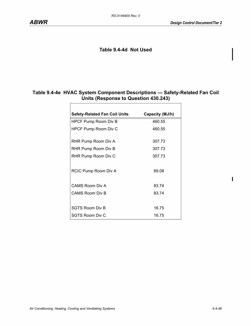
RS-5146900 Rev. 0
Design Control Document/Tier 2ABWR
Table 9.4-4d Not Used
Table 9.4-4e HVAC System Component Descriptions — Safety-Related Fan Coil Units (Response to Question 430.243)
Safety-Related Fan Coil Units Capacity (MJ/h)
HPCF Pump Room Div B 460.55
HPCF Pump Room Div C 460.55
RHR Pump Room Div A 307.73
RHR Pump Room Div B 307.73
RHR Pump Room Div C 307.73
RCIC Pump Room Div A 69.08
CAMS Room Div A 83.74
CAMS Room Div B 83.74
SGTS Room Div B 16.75
SGTS Room Div C 16.75
Air Conditioning, Heating, Cooling and Ventilating Systems 9.4-46

RS-5146900 Rev. 0
Design Control Document/Tier 2ABWR
Table 9.4-4f HVAC System Component Descriptions—Non-Safety-Related Heating Cooling Coils (Response to Question 430.243)
Heating/Cooling Coils QuantityCooling(MJ/h)
Heating(MJ/h)
R/B Secondary Containment HVAC 1 4848.48 3251.52
RIP ASD HVAC Division A 1 2110.15
RIP ASD HVAC Division B 1 2110.15
Table 9.4-4g HVAC System Component Descriptions—Non-Safety-Related Fans (Response to Question 430.243)
Fans Quantity Capacity (m3/h)
R/B Secondary Containment Supply Fans 3 (1 on standby) 84,250
R/B Secondary Containment Exhaust Fans 3 (1 on standby) 86,250
R/B Primary Containment Supply Fan 1 22,000
R/B Primary Containment Exhaust Fan 1 22,000
RIP ASD Division A Supply Fans 2 (1 on standby) 50,000
RIP ASD Division B Supply Fans 2 (1 on standby) 50,000
Table 9.4-4h HVAC System Component Descriptions—Non-Safety-Related Filters (Response to Question 430.243)
Filters Quantity Capacity (m3/h)
R/B Secondary Containment HVAC 3 (1 on standby) 86,250
R/B Primary Containment Intake HEPA Filter 1 22,000
R/B Secondary Containment Exhaust Fans 3 57,500 (each)
Air Conditioning, Heating, Cooling and Ventilating Systems 9.4-47

RS-5146900 Rev. 0
Design Control Document/Tier 2ABWR
Table 9.4-4i HVAC System Component Descriptions—Non-Safety-Related Air Handling Units (Response to Question 430.243) *
* The COL applicant shall supply equipment lists for the Service Building HVAC and the Radwaste Building HVAC System. See Subsection 9.4.10.1 for the Service Building, and 9.4.10.2 for the Radwaste Building.
Non–Safety-Related Air Handling Units Quantity Capacity (MJ/h)
Main Steam Tunnel 2 628.02
Refueling Machine Control Room 1 83.74
ISI Room 1 54.43
MG Set Room 2 321.84
C/B Non-Safety-Related Electric Room 1 211.01
R/B FPC Room 2 28.47
CRD Control Room 1 18.42
SPCU Pump Room 1 42.29
Air Conditioning, Heating, Cooling and Ventilating Systems 9.4-48

RS-5146900 Rev. 0
Design Control Document/Tier 2ABWR
Table 9.4-5 Turbine Island HVAC System - Non-Safety-Related Heating Cooling Coils
Heating/Cooling Coils QuantityCooling(MJ/h)
Heating(MJ/h)
Turbine Building HVAC 1 19,919.52 7,905.6
Turbine BuildingElectrical Equipment Area HVAC 2(1 on standby) 8,849.52 3,153.6
Table 9.4-5a Turbine Island HVAC System - Non-Safety-Related Fans
Fans Quantity Capacity (m3/h)
T/B HVAC Supply Fans 3 (1 on standby) 192,750
T/B HVAC Exhaust Fans 3 (1 on standby) 27,850
T/B HVAC Compartment Exhaust Fans 2 (1 on standby) 359,700
T/B HVAC Lube Oil Area Exhaust Fans 2 (1 on standby) 9,300
T/B EEA HVAC Supply Fans 2 (1 on standby) 245,200
T/B EEA HVAC Exhaust Fans 2 (1 on standby) 211,500
Table 9.4-5b Turbine Island HVAC System - Non-Safety-Related Filters
Filters Quantity Capacity (m3/h)
T/B HVAC Supply Filters 1 385,500
T/B HVAC Exhaust Filters 3 (1 on standby) 27,850
T/B HVAC Compartment Exhaust Filters 1 359,700
T/B HVAC Supply Filters 1 245,200
Air Conditioning, Heating, Cooling and Ventilating Systems 9.4-49

RS-5146900 Rev. 0
Design Control Document/Tier 2ABWR
Table 9.4-5c Turbine Island HVAC System - Non-Safety-Related Air Handling UnitsNon-Safety Related Air Handling Units Quantity Capacity (MJ/h)
Turbine Building HVAC
OG Holdup Room 2 (1 on standby) 68.76 (Cooling)11.88 (Heating)
Condenser Compartment Upper Area 3 (1 on standby) 582.48
Condenser Compartment Lower Area 3 (1 on standby) 567.36
MSR (A) Compartment 2 (1 on standby) 707.40
MSR (B) Compartment 2 (1 on standby) 703.44
Turbine Operation Area 2 (1 on standby) 605.88
IPB Cooling Unit Room 2 (1 on standby) 355.32
IPB Area 2 (1 on standby) 325.80
SCR Panel Room 2 (1 on standby) 355.32
Turbine Building Electrical Equipment Area HVAC
HVAC Supply Fans Room 2 (1 on standby) 246.24
Air Compressor Room 2 (1 on standby) 310.68
TCW Heat Exchanger Room 2 (1 on standby) 792.00
P/C Room 5 (2 on standby) 792.00
ASD (A), (B) Room 3 (1 on standby) 968.76
ASD (C), (D) Room 3 (1 on standby) 785.88
Electrical Equipment Room 2 (1 on standby) 469.08
Air Conditioning, Heating, Cooling and Ventilating Systems 9.4-50

RS-5146900 Rev. 0
Design Control Document/Tier 2ABWR
The following figures are located in Chapter 21:Figure 9.4-1 Control Building HVAC PFD (Sheets 1-5)
Figure 9.4-2a Turbine Building HVAC System Air Flow Diagram
Figure 9.4-2b Turbine Building HVAC System Control Diagram (Sheets 1-2)
Air Conditioning, Heating, Cooling and Ventilating Systems 9.4-51

RS
-5146900 Rev. 0
Air C
onditioning, Heating, C
ooling and Ventilating S
ystems
9.4-52
Design Control Document/Tier 2
ABWR
ystem Diagram
Figure 9.4-2c Turbine Building Electrical Equipment Areas (EEA) HVAC S
RS-5146900 Rev. 0
Design Control Document/Tier 2ABWR
The following figures are located in Chapter 21:
Figure 9.4-3 Secondary Containment HVAC System (Sheets 1-3)
Figure 9.4-4 Safety-Related Electrical Equipment HVAC System (Sheets 1-3)
Figure 9.4-5 Reactor Internal Pump ASD HVAC System
Figure 9.4-6 Not Used
Figure 9.4-7 Not Used
Figure 9.4-8 Drywell Cooling System P&ID
Air Conditioning, Heating, Cooling and Ventilating Systems 9.4-53

RS-5146900 Rev. 0
Design Control Document/Tier 2ABWR
Figure 9.4-9 Drywell Heat Load Area Drawing
DRYWELL HEAD AREA
TP .17370
TP .–1100
AREA 3LOWER
TP .23000
TP .12300
TP .21300
TP .–6600
AREA 4
AREA 1
AREA 5WETWELL AIR SPACE
AREA 2UPPER
Air Conditioning, Heating, Cooling and Ventilating Systems 9.4-54

RS-5146900 Rev. 0
Design Control Document/Tier 2ABWR
The following figure is located in Chapter 21:Figure 9.4-10 Radwaste Building HVAC (Sheets 1-3)
Air Conditioning, Heating, Cooling and Ventilating Systems 9.4-55