ac 2007-3087: a systems engineering entrepreneurship
TRANSCRIPT

AC 2007-3087: A SYSTEMS ENGINEERING ENTREPRENEURSHIP APPROACHTO COMPLEX, MULTIDISCIPLINARY UNIVERSITY PROJECTS
William Arrasmith, Florida TechWilliam W. Arrasmith received his Ph.D. from The Air Force Institute of Technology in Dayton,Ohio in Engineering Physics. He holds an M.S. degree in Electrical Engineering from theUniversity of New Mexico and a B.S. degree in Electrical Engineering from Virginia Tech. He iscurrently an Associate Professor in the Engineering Systems Department at the Florida Instituteof Technology. His research interests include adaptive optics, signal processing, imageprocessing, and applied systems engineering. He worked for 20 years for the United States AirForce as a scientist, engineer, educator, and acquisitions officer prior to his academic career.
© American Society for Engineering Education, 2007

A Systems Engineering Entrepreneurship Approach to Complex,
Multi-Disciplinary University Projects
Abstract: This paper presents a systems engineering entrepreneurship approach to developing projects at a
university that are complex, multi-disciplinary in nature, integration oriented, and that may span
departments, colleges, and have long completion schedules. Fundamental systems engineering principles are
used to manage cost, schedule, and performance aspects of projects as well as to manage and control project
risk. Entrepreneurial principles are used as part of the cost-benefit analysis in project evaluation. As an
illustrative example, we present a project to develop an adaptive optics and atmospheric turbulence
compensation system for a 0.8 meter optical telescope. A system engineering approach is used to identify and
document stakeholder requirements, establish a project baseline, and use a requirements driven methodology
to manage and control the project throughout its system development life-cycle. This approach is most
suitable for technically complex projects that require collaboration and integration of diverse activities and
resources as is often the case for multi-disciplinary projects or activities in centers of excellence or multi-
university research initiatives.
1.0 Introduction
The discipline of systems engineering has long been used as a tried-and-true means for
controlling, cost, schedule, and performance aspects of complex government and industrial
programs. In fact, for many DOD programs, a sound systems engineering approach is a pre-
requisite for any successful contractor bid1. At the same time, universities are increasingly
undertaking more complex, multi-disciplinary, collaborative ventures that range in scope from
establishing “Centers of Excellence” and multi-university initiatives to multi-disciplinary senior
design projects—robots, autonomous vehicles, alternative energy projects, and race car projects
and competitions to name a few.
Often, the successes, failures, and lessons learned from these projects are passed on from one
team to the next by word of mouth alone and no process exists for retaining corporate knowledge,
system optimization, or for implementing a spiral development process. Adopting a systems
engineering approach for multi-disciplinary, complex university projects would provide long-
term stability, a means for integrating the activities of diverse faculty, and a proven approach to
managing cost, schedule, and technical aspects of complex university projects/programs.
As an example, we present a systems engineering analysis/approach to providing an adaptive
optics and atmospheric turbulence compensating capability for a newly acquired 80 cm telescope
at our institution. Adding this capability would increase our telescopes spatial resolution up to
14 times over its current state. This is a highly complex, multi-disciplinary project that involves
optics, mechanical engineering, physics, math, electrical and computer engineering, computer
science, and systems engineering disciplines.
We present systems engineering processes, tools, and techniques that were used for the spiral
development of this project. Some examples include stakeholder identification and needs
assessments, development of a concept of operations, feasibility and risk analysis, requirements
engineering, functional analysis, and life-cycle planning2. With the entrepreneurship focus,
intellectual property, commercialization, marketing, spin-off technologies and return on

investment as well as other commercial and business oriented aspects are included as part of the
educational experience and as a means for promoting project growth3.
For clarity and completeness, the following organizational approach is adopted. Section 2.0
provides some technical background on optical imaging through atmospheric turbulence along
with the motivation and mechanics for incorporating atmospheric turbulence compensation
approaches such as post-processing turbulence compensation systems, adaptive optics systems,
or hybrid adaptive optics systems. Section 3.0 describes our process of implementing a system
engineering approach for the development and life-cycle support of an atmospheric turbulence
compensating imaging system. Section 4.0 provides some projected performance and simulation
results and Section 5.0 presents our conclusions. In this case, a system engineering
entrepreneurship methodology was applied to a charter adaptive optics system at the [our
university here] (Chaos-XXX) but this requirement driven, systematic approach can be used for
general multi-disciplinary, integration oriented, complex projects at academic institutions. This
approach has the added benefits of providing stability, traceability, configuration control, and an
established project baseline that opens the door for implementing successful, cost-effective,
multi-disciplinary, integration-oriented and technically complex projects/programs over arbitrary
time-frames in a high turn-over environment as would be expected using student teams.
2.0 Background
Before describing the system engineering entrepreneurship approach, we will present a little
background on atmospheric turbulence compensation and adaptive optics systems (ATC & AOS)
in order to gain an understanding of the scope of our technical project. The intent is not to
provide a complete technical treatment of ATC & AOS but to provide a general introduction and
overview of these types of systems to provide contextual information for Section 3.0 of this
paper. This section also indicates the complexity of this project and the need for multi-
disciplinary teams to successfully implement these types of systems.
In the optical part of the electromagnetic spectrum, atmospheric turbulence is the leading
contributor to loss of spatial resolution in imaging systems with entrance pupil apertures larger
than the atmospheric coherence length a.k.a. the Fried parameter4. Often, a reasonable value for
the Fried parameter is 8 cm. This means that without compensating for the effects of
atmospheric turbulence, large optical imaging systems such as those at our national observatories
would have no better spatial resolution than telescopes bought in the toy department of any retail
store. Figure 1 shows the effect of imaging space objects through atmospheric turbulence.
In Figure 1, light from a space-borne object (the star) has its electromagnetic field corrupted
by the atmosphere. For near-field atmospheric turbulence, such as is seen by an earth-bound
telescope imaging extra-terrestrial objects, the predominant effect of the turbulence is to corrupt
the phase of the incoming electromagnetic field5. The net effect is to spread the energy of the
star over the focal plane of the receiver as indicated by the “fuzzy blob” in Figure 1.
The major cause of atmospheric turbulence is the non-uniform heating and cooling of the
Earth’s surface by the sun6. Non-uniform heating and cooling of the Earth’s surface results

from variations in the thermal response of different materials when they are illuminated by solar
radiation. The cycle of heating and cooling through-out the day and night results in heat being
coupled into index of refraction changes that have altitude dependent spatial scales. The non-
uniform heating of the air gives rise to randomly sized and distributed pockets of air each having
a characteristic temperature. These pockets of air, also referred to as turbulent eddies, are the
cause for turbulent motion in airplane travel, twinkle effects of distant stars, and the blurring
effect on images as seen through an optical telescope. The altitude dependence of atmospheric
turbulence is discussed next.
The air near the surface is where most of the turbulent airflow in the atmosphere occurs. This
is caused mainly by the thicker atmosphere near the Earth’s surface and the solar and
atmospheric interaction with the surrounding physical environment such as terrain, physical
structures, wind, material properties, moisture, and humidity. A uniform topography, such as
grassy fields, and large bodies of water create uniform heat patterns and therefore less
turbulence.
Mid-altitude turbulence effects are determined largely by the topography upwind of the
observing site. By living downwind of a large city, or densely populated area, large structures
such as mountain ranges or other highly varied topography will create atmospheric turbulence.
This effect is seen in Figure 2. Downwind of a mountain peak, the airflow creates turbulent
eddies. This effect can prevail as far as 100 km downwind of the peak. If the terrain around an
observing site is uniform, then turbulence effects are reduced. Also, generally the higher an
observing site is positioned, the less atmospheric turbulence it experiences because of the
thinning atmosphere.
High altitude atmospheric turbulence effects are dominated by Jet streams. Wind shears at
around the 200-300 mb altitude level can cause images to appear very fuzzy, and devoid of fine
detail. Forecasts are available to help predict whether a Jet stream is present over your area.
Areas of the Northern hemisphere most affected by the Polar jet stream are the Central US,
Figure 1: The light from the star is refracted by the earth’s atmosphere resulting in a
fuzzy and blurry image.

Canada, North Africa, and Northern Japan. The Jet stream’s position varies with the seasons,
tending to move further South during the winter and spring months.
Refractive index changes have an impact on the optical wave-front as it travels through the
earth’s atmosphere. In a vacuum, light from a distant star would arrive at the telescope primary
mirror as a single planar wave-front. As discussed below, in the absence of an atmosphere and
system noises—note that the system noises can be minimized in well designed optical systems—
the only limit on spatial resolution would be the diameter of the telescope’s primary mirror a.k.a.
the entrance pupil aperture7. For the remainder of this paper, we assume that system effects are
negligible with respect to the effect of atmospheric turbulence. This is usually the case for well
designed optical systems. In the earth’s atmosphere, the tiny local variations in the index of
refraction of the atmosphere induce small phase changes that make the incoming plane wave
look more like a sheet of crumpled paper. These uncompensated atmospheric phase aberrations
in essence destroy an optical imaging systems resolving power.
Diffraction theory gives the spatial resolution limit of a telescope in the absence of any
atmospheric effects and system noises as 1.22 (λ /D) where, λ is the mean wavelength of the
optical field, and D is the diameter of the telescope’s entrance pupil8. This results in the
theoretical “best” resolution of a telescope (in vacuum with negligible system noises) given a
circular aperture.
Table 1 below gives the theoretical resolution in vacuum (in arc-seconds) for different size
telescopes at various wavelengths. For comparison purposes, the optical telescope at XXX has a
0.8 meter aperture. In practice at many observation sites the resolution they achieve through the
atmosphere with conventional astronomical imaging falls in the range of 0.3 - 10 arc-seconds at
visible wavelengths9.
Figure 2: Illustration of the effect of terrain on the turbulent flow of the atmosphere.
Site A is looking through less a less turbulent atmosphere and so would have better
“seeing” conditions than site B.

Table 1: The theoretically “best” resolution achievable (in arc-seconds) by conventional optical imaging
systems. Results are plotted for various mean wavelengths and circular aperture diameters in vacuum.
Unfortunately, because of the presence of atmospheric turbulence and system effects, an
uncompensated imaging system can not achieve the theoretical spatial resolutions listed in Table
1. Instead, the spatial resolution of an optical imaging system that is looking vertically through
atmospheric turbulence is given by the Fried parameter ro as 1.22 λ/ro10
. Atmospheric conditions
are such that the Fried parameter is usually in the range of 5 to 20 cm—typically towards the
lower end of the scale. The best expected performance improvement in angular or spatial
resolution of an optical imaging system that fully compensates for the effects of atmospheric
turbulence and has negligible system effects is obtained by dividing the attainable resolution
when looking through atmospheric turbulence by the diffraction limited resolution,
0r
Dximp =∆ , (1)
where impx∆ is the best possible increase in spatial resolution11
. As an example, for the 0.8 m
telescope here at the [our university goes here] and for a “seeing” parameter ro of 5 cm, we
would expect up to a 16-fold increase in the spatial resolution of our telescope by compensating
for the effects of atmospheric turbulence. This effect is simulated in Section 4.0 of this paper.
As can be seen by the preceding discussion, a multi-disciplinary team is required to
successfully develop an ATC & AOS. Expertise is required in diverse areas such as optical
systems design, image and signal processing, atmospheric physics, electrical and computer
engineering, electromagnetism, space sciences, mathematics, control systems, electro-optical
devices, systems engineering, mechanical engineering, and material science to name a few. As
such, this project serves as an excellent illustrative example of a technically complex, multi-
disciplinary, integration oriented project that spans many academic terms. The next section of
this paper discusses the system engineering approach used to systematically develop this project.
3.0 Approach
This Section presents the system engineering entrepreneurship approach used to develop the
Chaos-XXX. We discuss the development process as it pertains to our project; however, the
Pass
Band:
Wavelength
(nm)
0.8 meter
Diameter
1 meter
Diameter
2.5 meter
Diameter
10 meter
Diameter
B 450 0.137 0.11 0.044 0.011
V 550 0.168 0.134 0.054 0.013
R 650 0.198 0.159 0.063 0.016
I 850 0.259 0.207 0.083 0.021
J 1200 0.366 0.293 0.117 0.029
H 1600 0.488 0.39 0.156 0.039
K 2200 0.671 0.537 0.215 0.054
approach is general and has the following advantages for complex, multi-disciplinary, integration
oriented university projects,
1.0 Provides a requirement driven approach and change control system for focused
project development, impact assessments on schedule, cost, and performance,
resource allocation decisions, and cost-benefit analysis,
2.0 Embodies a system baseline for evolutionary development in spiral phases with
exit criteria for each phase,
3.0 Features an entrepreneurial component to assess marketability, profitability,
intellectual property, financial risk, business plan development, and tech transfer,
4.0 Contains a methodology for feasibility analysis, trade-off studies, and risk
assessments,
5.0 Takes a holistic approach to project development considering the entire project
over its life-cycle
The system engineering entrepreneurship approach is especially beneficial for technically
diverse, dynamic projects or programs that span departments, colleges, or universities and
require the integration of different technical components or technologies. The system
engineering entrepreneurship approach is also good for less complex but repetitive projects such
as senior design projects. Academic institutions by their very nature have a high turnover in
their student population and so a proven system for establishing a project baseline and controlled
project documentation would be a tremendous benefit for complex projects that take a long time
to complete.
Essential documents for integration oriented complex projects include stakeholder
identification and needs assessments, project’s scope, goals, and objectives, concept of
operations, the project plan, system requirements, feasibility and trade studies, risk assessments
and associated risk management plan, interface control documents, “build to” and “as-built”
design documentation, project test plans, test procedures, test results, as well as documentation
of the project maintenance concept, pre-planned product improvement, reliability,
maintainability, safety, and quality aspects of the project. To develop these documents and
establish the project baseline, a host of system engineering tools are available. Some powerful
examples include the quality functional deployment, analytical hierarchy process, functional
block diagrams, functional flow diagrams, quality engineering tools, project selection tools,
decision tools, and statistical process control tools, and designed experiments methods. Some of
these are presented as examples in the Chaos-XXX below.
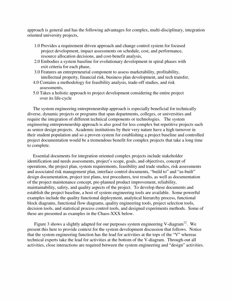
Figure 3 shows a slightly adapted for our purposes system engineering V-diagram12
. We
present this here to provide context for the system development discussion that follows. Notice
that the system engineering function has the lead for activities at the tops of the “V” whereas
technical experts take the lead for activities at the bottom of the V-diagram. Through-out all
activities, close interactions are required between the system engineering and “design” activities.

Figure 3: Generic system engineering V-diagram illustrating regions of responsibility for the systems
engineering activity versus the functional “expert”. Blocks on the right side of the V-diagram correspond to
documentation on the left side of the V-diagram11
.
When initiating a project or program, it is important to identify the stakeholders and
document their needs. This is shown in the top-left block of Figure 3. Stakeholders include
anyone that has an interest in the project including university leaders and administrators, end-
users of the project, existing and potential customers, technicians, maintenance and logistics
personnel, budget and financial personnel, contracting and legal personnel, relevant
governmental and regulatory counterparts, political and commercial interests, intellectual
property experts, marketing experts, and of course the members of the project development team
themselves.
Once the stakeholders are identified, their needs and requirements are agreed upon and then
documented13
. The agreed “stakeholder requirements” are then used to drive the rest of the
project development. Early on in the project development, it is useful to concisely capture and
illustrate the stakeholder requirements in a concept of operations. The CONOPS is operationally
oriented and serves to bring to focus the scope and nature of the project at hand14
. Often, a
graphical representation of the concept of operations is used to focus the project team on the task
at hand. Figure 4 illustrates the concept of operations for the Chaos-XXX.
Understand stakeholder
Requirements, Development of
System concepts
Develop system
Performance
specification
Develop “design-to”
specifics
Develop “build-to”
Documentation
Develop product
Inspect product
Perform verification Per “design-to” specs
Integrate system.
Verify system
performance
Validate system.
Demonstrate to user
System
Engineering
Responsibility
Functional
Expert
Responsibility
System Engineering V-Diagram

Figure 4: Concept of operations for the atmospheric turbulence compensation and adaptive optics system
planned for the 0.8 meter telescope at the [our university goes here].
The atmospheric turbulence compensation process starts when uncorrupted object information
such as the object brightness (w/m2; shown as the undistorted image at the top-left of Figure 4) is
degraded by atmospheric turbulence and system noise effects. The entrance pupil field
(represented by the distorted image in Figure 4) is severely degraded by atmospheric turbulence
and is further low-pass filtered by the entrance pupil plane aperture of the imaging system. The
distorted image shown is just a representation of the information at the entrance pupil aperture of
the imaging system and is more realistically proportional to the 2-D Fourier transform of the
shown distorted image. The beam splitter passes a portion of the optical field towards a wave-
front correcting device (shown as the deformable mirror), and a portion towards a wave-front
sensor. The wave-front sensor estimates the atmospheric turbulence induced phase across the
imaging systems entrance pupil and passes these results to either the wave-front correcting
device or to the high speed wave-front/image processing system (shown as software processing
at the bottom of Figure 4).
If only the high-speed software processing system is used (bottom of Figure 4), then post-
processing methods or high-speed software based atmospheric turbulence compensation methods
can be investigated and implemented—for instance the phase diversity method by Gonsalvez15
.
If instead the wave-front correcting device (deformable mirror, micro-mechanical mirror, or
liquid crystal) is used, then, when combined with the research grade camera, image frame-
grabber, and storage and display system, a traditional hardware based adaptive optics system is
obtained. Combined hardware and software based approaches such as partial compensation
methods can also be investigated by using both the high speed software processing capabilities
and sub-sampled, conventional adaptive optics systems.
In Figure 4, the hardware processing segment includes the beam splitter, wave-front sensor,
wave-front sensor processing system, flexible mirror controller, the deformable mirror, and any

beam steering and beam shaping optics required in the optical path of the imaging system. The
deformable mirror surface changes shape according to commands from the flexible mirror
controller system. The deformed mirror adjusts itself in real-time to remove the sensed
aberrations induced by system noise and atmospheric turbulence effects.
The software processing segment takes a feed from the wave-front sensor segment and/or
direct image plane data and applies predominantly software based algorithms to reconstruct the
image. High speed parallel processing hardware such as the Cellular Neural Network or Irvine
Sensor’s 3-D artificial neural network may be used as in-line or co-processors to increase the
processing throughput of the system16, 17
. One goal is to investigate high speed parallel
processing software to perform image correction in real-time or near real-time. The resultant
software reconstructed image can be compared to the reconstructed image obtained from the
Chaos-XXX providing for comparative analysis and system trade studies.
In order to maintain configuration control in a large, complex project, a requirements
management system (RMS) is essential. A good RMS serves as a repository for project/program
requirements and provides project control features such as traceability analysis, linking of the
requirements to the project’s qualification program (testing, reviews, meetings, etc.), and
provides a means to assign searchable attributes to the requirements. For the Chaos-XXX, we
used the Dynamic Object Oriented Requirements System (DOORS) developed by Telelogic to
capture and manage our requirements18
. We chose DOORS since it is widely used in industry,
the Department of Defense, and also by many of our commercial partners that develop large-
scale, technically complex programs.
Given the stakeholder requirements, and the concept of operations, feasibility and trade-off
studies were conducted. The purpose of these studies was to assess the performance of the
Chaos-XXX and also to generate the top-level system requirements for the project. To gain
some performance insights, an atmospheric turbulence compensation simulator was developed
using student teams to predict the performance of the telescope before and after the addition of
the Chaos-XXX19
.
Figure 5 shows the predicted before and after results using the atmospheric turbulence
simulator. The image on the left of Figure 5 shows a reference image of Mars obtained from the
Hubble Space Telescope. The central image corresponds to what would be seen by a 0.8 meter
telescope under long exposure imaging conditions without compensating for the effects of
atmospheric turbulence. The mean illuminating wavelength in the model is 550 nm.
The image on the right side of Figure 6 represents the best possible image attainable by fully
compensating for the effects of atmospheric turbulence. As can be seen, quite an increase in
spatial resolution is possible by incorporating a turbulence compensation system of some sort.
The stakeholder requirements, concept of operations, and simulation models were used to
develop system level requirements.
These system requirements were captured in the DOORS and a functional analysis was
conducted to identify the major system components. A top level functional block diagram is
illustrated in Figure 6. The project was broken into 3 phases or spiral developments. Spiral 1
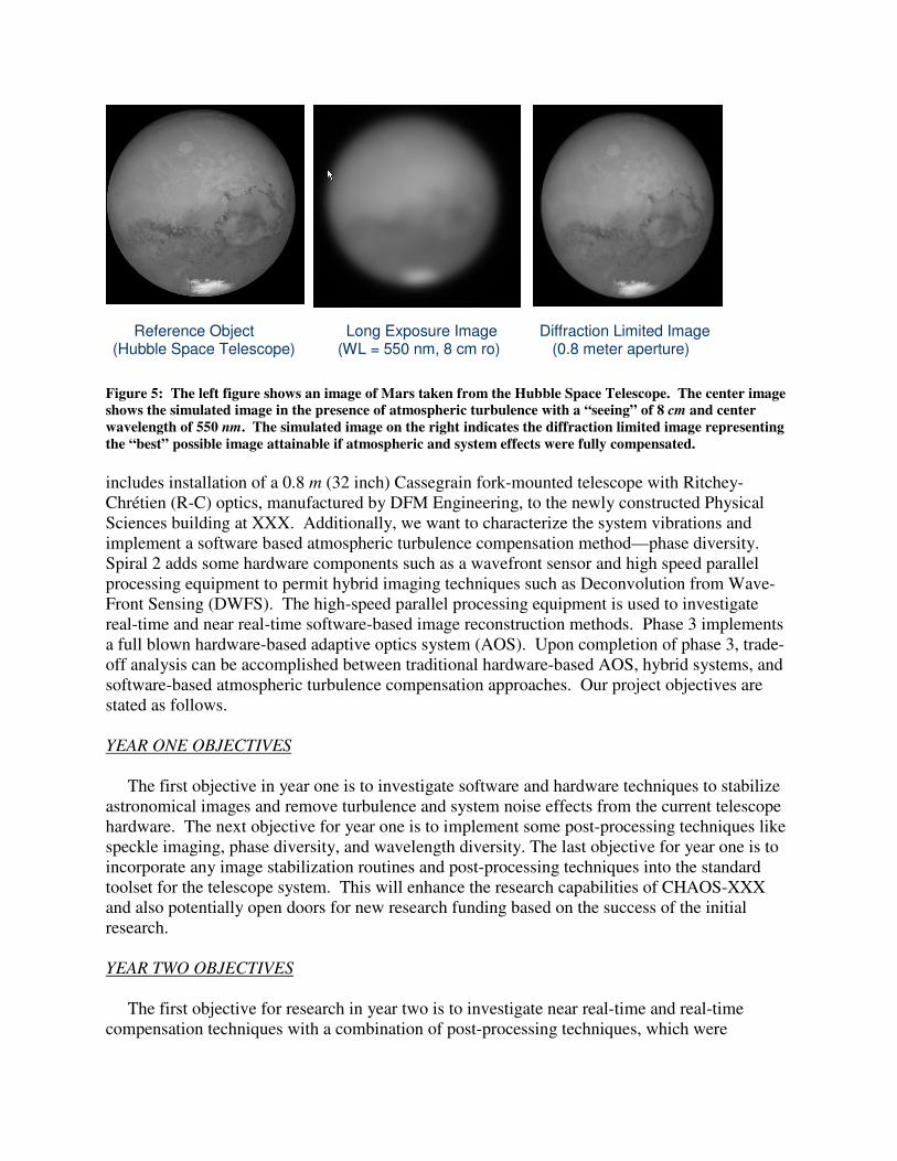
Figure 5: The left figure shows an image of Mars taken from the Hubble Space Telescope. The center image
shows the simulated image in the presence of atmospheric turbulence with a “seeing” of 8 cm and center
wavelength of 550 nm. The simulated image on the right indicates the diffraction limited image representing
the “best” possible image attainable if atmospheric and system effects were fully compensated.
includes installation of a 0.8 m (32 inch) Cassegrain fork-mounted telescope with Ritchey-
Chrétien (R-C) optics, manufactured by DFM Engineering, to the newly constructed Physical
Sciences building at XXX. Additionally, we want to characterize the system vibrations and
implement a software based atmospheric turbulence compensation method—phase diversity.
Spiral 2 adds some hardware components such as a wavefront sensor and high speed parallel
processing equipment to permit hybrid imaging techniques such as Deconvolution from Wave-
Front Sensing (DWFS). The high-speed parallel processing equipment is used to investigate
real-time and near real-time software-based image reconstruction methods. Phase 3 implements
a full blown hardware-based adaptive optics system (AOS). Upon completion of phase 3, trade-
off analysis can be accomplished between traditional hardware-based AOS, hybrid systems, and
software-based atmospheric turbulence compensation approaches. Our project objectives are
stated as follows.
YEAR ONE OBJECTIVES
The first objective in year one is to investigate software and hardware techniques to stabilize
astronomical images and remove turbulence and system noise effects from the current telescope
hardware. The next objective for year one is to implement some post-processing techniques like
speckle imaging, phase diversity, and wavelength diversity. The last objective for year one is to
incorporate any image stabilization routines and post-processing techniques into the standard
toolset for the telescope system. This will enhance the research capabilities of CHAOS-XXX
and also potentially open doors for new research funding based on the success of the initial
research.
YEAR TWO OBJECTIVES
The first objective for research in year two is to investigate near real-time and real-time
compensation techniques with a combination of post-processing techniques, which were
Reference Object (Hubble Space Telescope)
Long Exposure Image (WL = 550 nm, 8 cm ro)
Diffraction Limited Image (0.8 meter aperture)
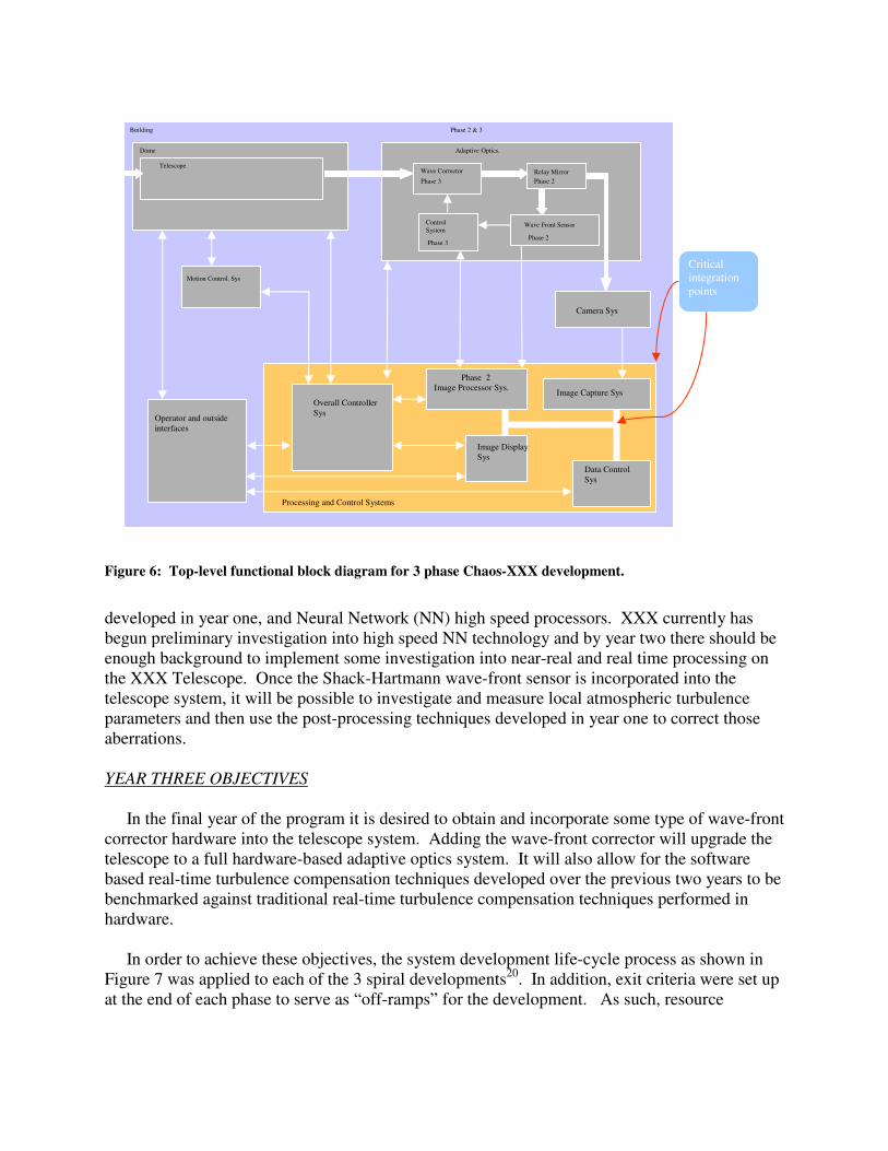
Figure 6: Top-level functional block diagram for 3 phase Chaos-XXX development.
developed in year one, and Neural Network (NN) high speed processors. XXX currently has
begun preliminary investigation into high speed NN technology and by year two there should be
enough background to implement some investigation into near-real and real time processing on
the XXX Telescope. Once the Shack-Hartmann wave-front sensor is incorporated into the
telescope system, it will be possible to investigate and measure local atmospheric turbulence
parameters and then use the post-processing techniques developed in year one to correct those
aberrations.
YEAR THREE OBJECTIVES
In the final year of the program it is desired to obtain and incorporate some type of wave-front
corrector hardware into the telescope system. Adding the wave-front corrector will upgrade the
telescope to a full hardware-based adaptive optics system. It will also allow for the software
based real-time turbulence compensation techniques developed over the previous two years to be
benchmarked against traditional real-time turbulence compensation techniques performed in
hardware.
In order to achieve these objectives, the system development life-cycle process as shown in
Figure 7 was applied to each of the 3 spiral developments20
. In addition, exit criteria were set up
at the end of each phase to serve as “off-ramps” for the development. As such, resource
Dome
Telescope
Motion Control. Sys
Adaptive Optics.
Building
Image Processor Sys.
Data Control
Sys
Image Display
Sys
Operator and outside
interfaces
Camera Sys
Image Capture Sys
Wave Corrector Relay Mirror
Wave Front Sensor Control
System
Phase 2
Phase 2 & 3
Phase 3 Phase 2
Phase 2 Phase 3
Overall Controller
Sys
Processing and Control Systems
Critical
integration
points

Figure 7: System engineering development process across the life-cycle
allocation decisions can be made at the completion of each spiral prior to proceeding to the
subsequent spiral development.
The system engineering development process (SEDP) is applied to each of the project
spirals and simultaneously to the overall project. This is done to capture as many of the system
life-cycle requirements as early as possible. Attributes are used in DOORS to track and
distinguish between project and spiral requirements.
The problem definition block includes identification of the stakeholders and their
requirements and the concept of operations. Trade studies and feasibility studies are
accomplished in a similar fashion for the entire project and then also for each of the individual
spirals. System modeling, analysis, and simulation are used to then define the system level
requirements. These are documented in the system specifications.
The maintenance and support requirements are considered and included in the project plan.
These include requirements for pre-planned product improvement (P3I) as well as special
logistics, storage, and disposal considerations. As the requirements are being developed,
technical performance measures (TPM) and associated metrics are identified corresponding to
each of the system requirements. The TPM’s are used in the overall qualification strategy to
verify and validate that the project requirements are satisfied. They are also used as “hard”
Problem definition
Trade studies/ feasibility analysis
System requirements
Maintenance & support
Establish technical performance measures
Conduct functional analysis
Requirement allocation
System design (analysis, synthesis, optimization)
Integrate design
Construction/production
System test/product eval
System use & support
System retirement & disposal
System engineering process in the life cycle

observables during the design phase of the project development and they are used in satisfaction
arguments during testing of the completed project.
Functional analysis is accomplished using tools such as the functional block diagram and
functional flow diagram to iteratively define the project components based on the system
requirements. The system requirements are then allocated to the identified functional blocks.
Modeling and simulation may be used to derive additional requirements if the collection of
requirements is deemed incomplete.
The requirements development, functional analysis, and requirements allocation process is
continued until sufficient requirements detail exists to initiate the design process. The
requirements are captured in DOORS and are organized into documents such as the top-level
system specification (A-specification) and lower lever detailed requirements specifications (B-
specification, C-specification, D-specification, and E-specification).
Test plans and procedures are developed based on the requirements and interface control
documents (ICD’s) are used to control project interfaces. The ICD’s are extremely useful in
projects were different groups are developing different components of the project. ICD’s are
very useful in project integration.
The design process starts by first analyzing the complete set of project requirements. Various
design options are synthesized and the optimal solution is selected. An excellent tool for
conducting trade-off analysis and component selection is the analytical hierarchy process
(AHP)21
. We used the AHP method to aid in the component selection of our research grade
cameras, system controllers, and adaptive optics and turbulence compensation devices.
The requirements and design documents are used to “build” the project. Upon completion,
the project (or project spiral) is tested according to its qualification documentation and the
project is placed in use upon successful satisfaction of the all project requirements. Once in use,
the maintenance and support strategy is implemented and the pre-planned product improvement
(PPPI) strategy is initiated. At the end of its useful life, the product, process, system, or service
is retired according to plan. The next section discusses our results.
4.0 Results
We implemented the system development life-cycle process illustrated in Figure 7 and
planned for a 3 spiral ATC & AOS development effort. We used student teams to develop an
atmospheric turbulence simulator and also software based atmospheric turbulence compensation
system based on the phase diversity technique. Figure 8 shows our implemented phase diversity
method applied to a simulated satellite object. The atmospheric turbulence simulator was used to
generate controllable amounts of atmospheric turbulence to degrade the reference object shown
at the top of Figure 8.
In phase diversity, an in-focus and de-focused image are used as inputs to the atmospheric
turbulence compensation algorithm and these two images are shown on the bottom left of Figure

Figure 8: Phase Diversity atmospheric turbulence compensation simulation. The top image is the
unaberrated reference object of a satellite model in the midst of clutter. The bottom left image is blurry
image of the reference object as viewed with a Fried parameter of 8 cm at a center wavelength of 550 nm.
The bottom-center image is the identically aberrated image as to its left but with an additional 1 wave of
defocus added. The bottom two images are used as inputs to the phase diversity algorithm and the bottom
right image is recovered from the phase diversity reconstruction algorithm.
8. An iterative post processing algorithm is used to remove the atmospheric turbulence effects.
The PD corrected image is shown on the bottom right of Figure 8.
Student design teams in different classes over several semesters were used to develop the
system documentation for the Chaos-XXX, develop the atmospheric turbulence simulator, and
implement the phase diversity atmospheric turbulence compensation technique.
To date, completed documentation and analysis include stakeholder requirements, benchmark
studies, concept of operations, feasibility and trade studies, system requirements analysis,
requirements specifications, risk analysis, functional analysis, design and interface
documentation, program plan, work breakdown structure, linear responsibility chart, project
master schedule, and project budget and resource requirements for all 3 spirals.
Entrepreneurial aspects of the project such as intellectual property, tech transfer, marketability,
and financial/commercialization considerations may at the discretion of the principle investigator
also be included as part of the project development strategy. If desired, these can play a roll in
project selection, ranking, and satisfaction of spiral exit criteria.
Reference Object
Blurred Image (WL = 550 nm, 8 cm ro)
PD Corrected Image (0.8 meter aperture)
Defocused Image (1 wave of Defocus)

5.0 Conclusions
A systems engineering entrepreneurship approach was presented for controlling technically
complex, integration oriented projects at academic institutions. This approach is ideal for multi-
disciplinary teams at universities and colleges that are engaged in activities and projects that
require the integration of diverse resources. The approach is not as effective for individual
research efforts or repetitive, non-complex projects. Examples where the systems engineering
entrepreneurship approach can help include centers of excellence, multi-department activities,
inter-collegiate, or multi-university projects or senior design teams.
As an example, a technically complex, multi-departmental and inter-collegiate project to
provide an atmospheric turbulence compensation and adaptive optics system for our 0.8 m
telescope was presented. Student design teams were used to provide the project analysis,
documentation and to build an atmospheric turbulence simulator. Student design teams were
also used to implement a software-based atmospheric turbulence compensation approach known
as phase diversity.
In addition to the systems engineering approach, entrepreneurial considerations such as
intellectual property, profit potential, marketability, and SWOT analysis can be considered for
go/no-go decisions during exit criteria evaluations between spiral developments. The
combination of the fundamental systems engineering principles with entrepreneurial
considerations makes for a solid approach to developing technically complex projects at
academic institutions.
6.0 Acknowledgements
I would like to thank the many students who worked on this project. In particular, I would
like to thank Shigeo Azuma, John Green, and Don Bryant for the fundamental systems
engineering work, Joe Elam for the lions share of the atmospheric turbulence simulator, Mark
Bielak and Rachael Singer for work with the high-speed parallel processing aspects of this
project, T.J. Misilo for the image stabilization simulator, and for the many other students who
contributed selflessly to make this project a success.
7.0 References
1. Department of the Air Force. Memorandum from SAF/AQ to all PEOs/DACs/Single
Managers, Incentivizing Contractors for Better Systems Engineering, 6 Jan 03.
2. Blanchard, B. S., System Engineering Management, 3rd
Ed. New Jersey: John Wiley
& Sons, 2003.
3. D’Cruz, Carmo and Tom O’Neal: Turning Engineers into Entrepreneurs and
Transforming a Region. Proceedings of the 2004 American Society for
Engineering Education (ASEE) Annual Conference. Salt Lake City. UT June 23-25,
2004.
4. Roggemann, Michael C., and Byron Welsh, Imaging through Turbulence, CRC Press
(1996).

5. Noll, R. J., “Zernike Polynomials and atmospheric turbulence,” J. Opt. Soc. Am., Vol.
66, pp. 207-211, 1976.
6. Roddier, F., “The effects of atmospheric turbulence in optical astronomy,” in Progress
in Optics, Vol. 19, E. Wolf, ed. (North-Holland, Amsterdam, 1981)
7. Goodman, J., Introduction to Fourier Optics, McGraw-Hill (1976)
8. Guenther, R., Modern Optics, Wiley (1990)
9. Roggemann, M. C., “Limited degree-of-freedom adaptive optics and image
reconstruction,” Applied Optics, Vol. 30, No. 29, pp. 4227-4233, 10 October, 1991.
10. Fried, D. L., “Statistics of a Geometric representation of Wavefront Distortion,”
J. Opt. Soc. Am., Vol. 55, No. 11, pp. 1427-1435.
11. Arrasmith, W. W., “Unconventional optical imaging using a high speed, neural
network based smart sensor”, Defense and Security Symposium, Orlando,
FL, April 16, 2006.
12. Blanchard, B. S., System Engineering Management, 3rd
Ed., pp. 47, Wiley (2003)
13. Hull, E., Jackson, K., and Dick, J., Requirements Engineering, 2nd
Ed., Springer (2005)
14. Feaga, K.P., Lt Col, USAF. “The USAF Capabilities Based CONOPS Construct.” Unpublished research article,
Air War College, Carlisle Barracks, PA, 2004.
15. Gonsalves, R. A., “Phase Retrieval from Modulus Data,” J. Opt. Soc. Am., Vol. 66,
No. 9, September 1976.
16. Chua, L. O., and Roska, T., Cellular neural networks and visual computing
foundations and applications, Cambridge University Press (2002).
17. 3-DANN Specifications sheet, obtained from Irvine Sensors homepage at,
http://www.irvine-sensors.com, (cited November, 2006).
18. DOORS product literature, obtained from Telelogic homepage at,
http://www.telelogic.com, (cited November, 2006).
19. Arrasmith, W. W., “High Speed Atmospheric Turbulence Compensation using a
Cellular Neural Network”, Military Sensing Symposium: Passive Sensors, Orlando,
FL, February 13, 2006.
20. Blanchard, B. S. and Fabrycky, W. J., Systems Engineering and Analysis, 4th
Ed., Pearson Prentice Hall (2006)
21. Saaty, T. L., Vargas, L., Fundamentals of Decision Making and Priority Theory with the Analytical Hierarchy
Process, Analytical Hierarchy Process Series, Vol. 6, RWS Publishing (2000)