accu-flo wellhead installation and operation manual flex hose ... accu-flo™ wellhead adapter kits...
TRANSCRIPT

2001 CES-LANDTEC, 850 South Via Lata, Suite 112, Colton, CA 92324 U.S.A. Accu-Flo is a product trademark.
The CES-LANDTEC ACCU-FLOW wellhead is protected by U.S. Patent number 5458006
Accu-Flo™ Installation and Operation Manual CES-Landtec Release Date: February 25, 2005
Accu-Flo WellheadInstallation and
Operation Manual

Accu-Flo WellheadTable of Contents
2001 CES-LANDTEC, 850 South Via Lata, Suite 112, Colton, CA 92324 U.S.A. Accu-Flo is a product trademark.
The CES-LANDTEC ACCU-FLOW wellhead is protected by U.S. Patent number 5458006
Accu-Flo™ Installation and Operation Manual CES-Landtec Release Date: February 25, 2005
Guarantee .............................................................................................................................1Owner Registration................................................................................................................1Additional Information and Technical Assistance ..................................................................1
INTRODUCTION...................................................................................................................2Accu-Flo Shipment ................................................................................................................3Other CES-LANDTEC/Accu-Flo™ products..........................................................................4
ACCU-FLO ™ WELLHEAD INFORMATION........................................................................4Accu-Flo Adapter Kit Parts necessary for installation............................................................5Before You Begin ..................................................................................................................5
PROCEDURE FOR INSTALLING ACCU-FLO WELLHEADSOverall Summary...................................................................................................................7Beginning the InstallationStep 1A. Installing the Accu-FloTM Wellhead to a Vertical Well Casing .................................8
Slip or Plain End Vertical Well Casing .............................................................................8Flanged Vertical Well Casing ..........................................................................................9
Step 1B. Installing the Accu-Flo™ Wellhead on a Horizontal Pipe......................................11Slip or Plain End Horizontal Pipe ...................................................................................11Flanged Horizontal Pipe.................................................................................................11
Step 2. Attach the Flex Hose to the Gate Value Assembly .................................................12Step 2A: Cementing the PVC Flex Hose to the Valve Assembly.........................................12Step 2B: Attaching the PVC Reinforced Corrugated Flex Hose to the Valve Assembly......13Step 2C: Attaching the Composition Rubber Flex Hose to Valve Assembly .......................14Step 3. Install the flex hose to the header or lateral. ...........................................................14Step 3A: Cement the PVC Flex Hose to the Header or Lateral...........................................15Step 3B: Attaching the PVC Reinforced Corrugated Flex Hose to the Header or Lateral .................................................................................................................................16Step 3C: Attaching the Composition Rubber Flex Hose to the Header or Lateral ...............18
FIELD OPERATIONSMethods of LFG Control ......................................................................................................20Well Field Adjustment-Purpose and Objectives...................................................................21Taking Measurements at the Accu-Flo Wellhead................................................................21Using the GEM-500 ™ to Gather Data................................................................................21Reading the Accu-Flo Wellhead – Using Standard Field Instruments .................................23Determining the Gas Flow Rate ..........................................................................................24Setting Gas Flow Rates.......................................................................................................24Other LFG Data...................................................................................................................25
ACCU-FLO WELLHEAD MAINTENANCE PROCEDURESTube Cap, Impact Tube and Pressure Ports Assembly.......................................................26Flow Control Gate Valve & Gas Sample Port ......................................................................28

Accu-Flo WellheadTable of Contents - Continued
2001 CES-Landtec, 850 South Via Lata, Suite 112, Colton, CA 92324 U.S.A. Accu-Flo is a product trademark.
The CES-LANDTEC ACCU-FLOW wellhead is protected by U.S. Patent number 5458006
Accu-Flo™ Installation and Operation Manual CES-Landtec Release Date: February 25, 2005
PVC Flex Hose ............................................................................................................. 29Measurement Tube Assembly and PVC Pipe Fittings................................................... 29
APPENDIX A SCHEDULE 80 PVC SOLVENT CEMENT INSTRUCTIONSHow It Works................................................................................................................. 30The Gluing Environment................................................................................................ 30Primers/Cleaners........................................................................................................... 30Step 1 – Apply Primer ................................................................................................... 31PVC Solvent Cement .................................................................................................... 31Step 2 – Apply Cement ................................................................................................. 32Applicator and Other Material Requirements................................................................. 32Final Warnings – Handling Solvent Cements and Primers............................................ 33
APPENDIX B LANDFILL GAS FIELD OPERATIONSLandfill Gas Generation................................................................................................. 34Subsurface Fires ........................................................................................................... 35Techniques for Controlling Landfill Gas......................................................................... 35Well Field Monitoring..................................................................................................... 37Making Well Field Adjustments .................................................................................... 38Well Field Adjustment - Criteria ..................................................................................... 39Establishing Target Flows ............................................................................................. 40Well Field Optimization.................................................................................................. 40Migration Control – Dealing With Poor Methane Quality ............................................... 40CES-LANDTEC Technical Tips ..................................................................................... 40
APPENDIX C ACCU-FLO WELLHEAD FLOW CHARTS

2001 CES-LANDTEC, 850 South Via Lata, Suite 112, Colton, CA 92324 U.S.A. Accu-Flo is a product trademark.
The CES-LANDTEC ACCU-FLOW wellhead is protected by U.S. Patent number 5458006
Accu-Flo™ Installation and Operation Manual CES-Landtec Release Date: February 25, 2005 Page 1
CES-LANDFILL CONTROL TECHNOLOGIES
Accu-Flo™ Wellhead GUARANTEE
CES-Landfill Control Technologies (CES-LANDTEC) Guarantees Your Satisfaction. We guarantee that all CES-LANDTEC Accu-Flo™ Wellheads will work in the appropriate landfill application for twelve months after installation or fifteen months after shipment (whichever comes first). If you, the registered owner during this period, are not fully satisfied, CES-LANDTEC will repair, replace or refund the purchase price of the Accu-Flo™ Wellheads returned to us. Any warranty of merchantability or fitness for purpose is specifically disclaimed and any claim based on warranty or otherwise, either expressed or implied, is limited to a purchase price refund.
OWNER REGISTRATION
The final landfill owner, or operator should register the wellheads with CES-LANDTEC. Because CES-LANDTEC products are often purchased by a contractor or subcontractor, CES-LANDTEC does not always know the ultimate owner. Please phone CES-LANDTEC at (800) LANDTEC or (909) 783-3636 and ask for a sales representative to register these products for the guarantee and to receive additional product support.
Additional Information and Technical Assistance
We are here to help and assist you in installing, using and repairing your Accu-Flo™ Wellheads. Please phone us at (800) LANDTEC or (909) 783-3636 any business day(8 a.m. to 5 p.m. Pacific Time) with your landfill gas management questions or problems. Email us at: [email protected] or review the technical support page on the web at: www.ces-landtec.com

2001 CES-LANDTEC, 850 South Via Lata, Suite 112, Colton, CA 92324 U.S.A. Accu-Flo is a product trademark.
The CES-LANDTEC ACCU-FLOW wellhead is protected by U.S. Patent number 5458006
Page 2 Accu-Flo™ Installation and Operation Manual CES-Landtec Release Date: February 25, 2005
Introduction
This manual provides installation instructions and operation and maintenance procedures for CES-LANDTEC Accu-Flo™ Wellheads. Accu-Flo™ well heads are designed specifically for installation in landfill gas (LFG) extraction systems. The wellheads are available in two configurations -- vertical and horizontal which are shown in the drawing below:

2001 CES-LANDTEC, 850 South Via Lata, Suite 112, Colton, CA 92324 U.S.A. Accu-Flo is a product trademark.
The CES-LANDTEC ACCU-FLOW wellhead is protected by U.S. Patent number 5458006
Accu-Flo™ Installation and Operation Manual CES-Landtec Release Date: February 25, 2005 Page 3
Accu-Flo™ SHIPMENT
Accu-Flo™ wellhead models are shipped as follows:
Accu-Flo™ main unit (measurement tube assembly and valve).
Hose kits (ITC Flex hose, corrugated hose or Spa hose) as ordered.
Installation and Operation Manual (one per order)
Product Registration Card (one per order)
Temperature Gauge Assembly (one per 10 wellheads upon request)
Shipping Dimensions and WeightsWellhead
Size & TypeDimensions
A & BActual Weight Shipping Weight
2 per Box1 ½” Vertical
AF2V-PV-015-2-G 18.5” x 6” x 55” 10 lbs. 25 lbs.
1 ½” HorizontalAF2H-PV-015-2-G 12.5” x 8” x 68” 13 lbs. 30 lbs.
2” VerticalAF2V-PV-020-2-G 18.5” x 6” x 55” 11 lbs. 25 lbs.
2” HorizontalAF2H-PV-020-2-G 12.5” x 8” x 68” 13 lbs. 30 lbs.
3” Vertical– 2” ValveAF2V-PV-030-2-G 18 x 9 x 65 17 lbs. 40 lbs.
3” VerticalAF2V-PV-030-3-G 18 x 9 x 65 26 lbs. 60 lbs.
3” HorizontalAF2H-PV-030-3-G 18 x 9 x 65 30 lbs. 68 lbs.
*2” Flex Hose5 ft./Hose Kit N/A 0.75 lbs./ft. 3.75 lbs./Wellhead
*3” Flex Hose5 ft./Hose Kit N/A 1.2 lbs./ft. 6 lbs./Wellhead
* If several Hose kits are ordered the hose is usually not precut and is shipped in rolls.

2001 CES-LANDTEC, 850 South Via Lata, Suite 112, Colton, CA 92324 U.S.A. Accu-Flo is a product trademark.
The CES-LANDTEC ACCU-FLOW wellhead is protected by U.S. Patent number 5458006
Page 4 Accu-Flo™ Installation and Operation Manual CES-Landtec Release Date: February 25, 2005
Other CES-LANDTEC/Accu-Flo™ products
CES-LANDTEC has other products available that supplement or enhance the Accu-Flo™ Wellhead. Some of these products are mentioned in various sections of this manual.
Accu-Flo™ Wellhead Adapter Kits are the various fittings necessary to connect the Accu-Flo™ wellhead to PVC and PE well casings and pipes.
CES-LANDTEC's Well-Bore Seal is a dense PVC sheeting that provides a durable, impermeable membrane seal installed around the top of a PVC vertical well casing to prevent well-bore air intrusion and LFG emissions.
CES-LANDTEC's GEM-500™ (Gas Extraction Monitor) utilizes all the features of the Accu-Flo™ wellhead to speed up data acquisition for % methane, % carbon dioxide, % oxygen, temperature, and gas flow and then stores the information in a notebook sized instrument. Data can be downloaded to a personal computer.
CES-LANDTEC’s GEM™2000 (Gas Extraction Monitor) is the latest instrument designed to use all of the Accu-Flo features for reliable, repeatable results. The GEM™2000 analyzes landfill gas samples for the Methane, Carbon Dioxide and Oxygen content, calculates & displays gas flow rate and stores the data for download.
CES-LANDTEC's DataField software takes data from the GEM-500 and other sources and produces various management and regulatory reports.
Accu-Flo™ Wellhead Information
This section provides supplemental information for Accu-Flo™ wellheads. Specific procedures for installing your Accu-Flo™ wellhead will vary depending upon the model, the size and type of the well casing and header/lateral piping comprising the LFG extraction system. Before beginning installation, read through this entire section.
Additional parts and supplies are necessary to properly install the Accu-Flo™ wellhead. Make sure you have the necessary supplies, parts, tools and equipment before installing. CES-LANDTEC can supply adapter kits (see table below).

2001 CES-LANDTEC, 850 South Via Lata, Suite 112, Colton, CA 92324 U.S.A. Accu-Flo is a product trademark.
The CES-LANDTEC ACCU-FLOW wellhead is protected by U.S. Patent number 5458006
Accu-Flo™ Installation and Operation Manual CES-Landtec Release Date: February 25, 2005 Page 5
Accu-Flo™ Adapter Kit Parts necessary for installation
Adapter Kits for Slip/Socket vertical or horizontal installation:Wellhead Size Casing/Pipe Size Adapter Kit Part Number1 ½” Wellhead 2” (2.375’ O.D.) AKT-EP-015-020S
3” (3.5” O.D.) AKT-EP-015-030S4” (4.5” O.D.) AKT-EP-015-040S6” (6.625” O.D.) AKT-EP-015-060S
2” Wellhead 2” (2.375’ O.D.) AKT-EP-020-020S3” (3.5” O.D.) AKT-EP-020-030S4” (4.5” O.D.) AKT-EP-020-040S6” (6.625” O.D.) AKT-EP-020-060S8” (8.625” O.D.) AKT-EP-020-080S
3” Wellhead 4” (4.5” O.D.) AKT-EP-030-040S6” (6.625” O.D.) AKT-EP-030-060S8” (8.625” O.D.) AKT-EP-030-080S
Adapter Kits for Flanged vertical or horizontal installation:Wellhead Size Casing/Pipe Size Adapter Kit Part Number1 ½” Wellhead 2” (2.375’ O.D.) AKT-EP-015-020F
3” (3.5” O.D.) AKT-EP-015-030F4” (4.5” O.D.) AKT-EP-015-040F6” (6.625” O.D.) AKT-EP-015-060F
2” Wellhead 2” (2.375’ O.D.) AKT-EP-020-020F3” (3.5” O.D.) AKT-EP-020-030F4” (4.5” O.D.) AKT-EP-020-040F6” (6.625” O.D.) AKT-EP-020-060F8” (8.625” O.D.) AKT-EP-020-080F
3” Wellhead 4” (4.5” O.D.) AKT-EP-030-040F6” (6.625” O.D.) AKT-EP-030-060F8” (8.625” O.D.) AKT-EP-030-080F
Before You BeginReview your landfill permits for special restrictions or procedures that must be observed
if excavation, trenching or other work is required for installation of Accu-Flo™ wellheads.
Read the introductory statements of each step to determine which instructions apply to your particular Accu-Flo™ wellhead model and LFG extraction system.

2001 CES-LANDTEC, 850 South Via Lata, Suite 112, Colton, CA 92324 U.S.A. Accu-Flo is a product trademark.
The CES-LANDTEC ACCU-FLOW wellhead is protected by U.S. Patent number 5458006
Page 6 Accu-Flo™ Installation and Operation Manual CES-Landtec Release Date: February 25, 2005
Obtain the following items:
Appropriate coupling/flange and reducer fittings for your well casing. (See tables above)
Any additional piping and/or fittings necessary to connect the wellhead flex hose to the extraction system.
PVC Primer and PVC solvent cement for PVC pipe, adapter fittings and flexible PVC hose as necessary. Several types of PVC cement are available and the proper type should be used depending on the type and size of the materials being cemented together. See Appendix A for additional PVC primer/gluing information and instructions.
High-grade vacuum grease is recommended for installation of vertical Accu-Flo™ wellheads. Dow Corning High Vacuum Grease is a silicone lubricant for glass stopcocks, joints, and glass-rubber connections. It resists most chemicals, is heat stable and inert. It is available in several sizes. CES-LANDTEC stocks the 5.3 oz tube or call Dow at (800) 248-2481 and ask for the distributor nearest you.
Tools -- including screw drivers, pliers, wrenches, emery cloth, saws, rags, glue rollers or brushes, etc. which can facilitate installation.
Safety equipment as required by site conditions.
Measurement equipment -- to take data after installation.
Paint or marker for well identification.
As a general safety rule, CES-LANDTEC recommends that two persons be used to install Accu-Flo™ wellheads if extensive use of power equipment or excavation is required. Also, during hot weather installations (above 90°F), two persons are required to insure that the solvent cement is applied quickly, before the solvents begin to dry and set-up.
CAUTION: Review your company’s landfill gas (LFG) health and safety policies and procedures prior to attempting any work at a landfill gas site. Federal, state and local regulations establish health and safety standards that regulate work at LFG sites.

2001 CES-LANDTEC, 850 South Via Lata, Suite 112, Colton, CA 92324 U.S.A. Accu-Flo is a product trademark.
The CES-LANDTEC ACCU-FLOW wellhead is protected by U.S. Patent number 5458006
Accu-Flo™ Installation and Operation Manual CES-Landtec Release Date: February 25, 2005 Page 7
Procedure for Installing Accu-Flo™ Wellheads
Overall SummaryThe installation procedure is divided into three sections as follows:
STEP 1. Install the Accu-Flo™ Wellhead onto the well casing, header or lateral.
STEP 1A.Installing THE Accu-Flo™ wellhead to a vertical well casing.
Slip or plain end well casing, header or lateral.
Flanged well casing, header or lateral.STEP 1B. Installing the Accu-Flo™ wellhead to a horizontal well casing, header or lateral.
Slip or plain end well casing, header or lateral.
Flanged well casing, header or lateral.
STEP 2. Attach the flex hose to the gate valve assembly of the Accu-Flo™ wellhead.
STEP 2A. Cement the PVC flex hose to the valve assembly.STEP 2B. Attach the PVC reinforced corrugated flex hose to the valve assembly.STEP 2C. Attach a composition rubber flex hose to the valve assembly.
STEP 3. Attach the flex hose to the header or lateral pipe.
STEP 3A. Cementing PVC flex hose to the header or lateral.STEP 3B Attach the PVC reinforced corrugated flex hose to the header or lateral.STEP 3C Attach a composition rubber flex hose to the header or lateral.
Warning: NEVER CUT THE MEASUREMENT TUBE ASSEMBLY OF ANY ACCU-FLO™ WELLHEAD. The length of the measurement tube assembly has been designed and tested at its current length. Any alterations to the measurement tube assembly will alter the differential pressure data taken at the wellhead and can compromise flow accuracy.

2001 CES-LANDTEC, 850 South Via Lata, Suite 112, Colton, CA 92324 U.S.A. Accu-Flo is a product trademark.
The CES-LANDTEC ACCU-FLOW wellhead is protected by U.S. Patent number 5458006
Page 8 Accu-Flo™ Installation and Operation Manual CES-Landtec Release Date: February 25, 2005
Beginning the Installation
Drawing 1A-1 (Slip or plain end connection)
Step 1A. Installing the Accu-Flo™ Wellhead to a Vertical Well Casing
This section gives the instructions for installing the Accu-Flo™ wellhead to a slip or flanged well casing. Go to Step 1B for horizontal installation. Proceed to the proper section below depending on the well casing connection slip or flanged.
Slip or Plain End Vertical Well Casing
This procedure is for Vertical Slip Well Casings. See drawing 1A-1
1. Measure the outer diameter (O.D.) of the vertical well casing.2. Determine the necessary adapter kit to fit the casing diameter. (See Accu-Flo™
Adapter Kit Chart on page five for the necessary adapter kit.)

2001 CES-LANDTEC, 850 South Via Lata, Suite 112, Colton, CA 92324 U.S.A. Accu-Flo is a product trademark.
The CES-LANDTEC ACCU-FLOW wellhead is protected by U.S. Patent number 5458006
Accu-Flo™ Installation and Operation Manual CES-Landtec Release Date: February 25, 2005 Page 9
3. Combine the coupling, reducer bushing and the Accu-Flo™ Wellhead to determine that they fit together for the given well casing size. See Drawing 1A-1.
4. Loosen the stainless steel clamps on the adapter kit coupling. Do not remove clamps from coupling.
5. Slide coupling over the plain end of the well casing.6. Determine the desired location of the reducer bushing on the Accu-Flo™ wellhead
measurement tube. Apply a light coating of vacuum grease to the inside surface of the reducer and slide the bushing on to the Accu-Flo™ wellhead measurement tube.
7. Place the wellhead assembly into the well casing. Determine the desired orientation of the wellhead and slide adapter kit bushing into coupling on the top of the well casing. Tighten stainless steel clamps to 60 inch-lbs. torque.
8. Turn the Accu-Flo™ Wellhead valve handle clockwise to shut the valve and stop landfill gas from escaping from the wellhead.
9. Proceed to Step 2 for attaching the flex hose.
Flanged Vertical Well Casing
This procedure is for Vertical Flanged Well Casings. See drawing 1A-2
1. Measure the outer diameter (O.D.) of the vertical well casing.2. Determine the necessary flanged adapter kit to fit the casing diameter. (See Accu-Flo™ Adapter Kit Chart on page five for the necessary adapter kit.)
3. Combine the flange, couplings, reducer bushing and the Accu-Flo™ Wellhead to determine that they fit together for the given well casing size. See Drawing 1A-2.
4. Put the neoprene flange gasket, provided with the adapter kit onto the well casing flange.
5. Use two open-ended wrenches to bolt the Van Stone spigot flange to the well casing flange with the bolts provided. Make sure the gasket is properly positioned between the two flanges and do not overtighten. (See drawing 1A-2)
6. Loosen the stainless steel clamps on the adapter kit coupling. Do not remove clamps from coupling.
7. Slide coupling over the plain end of the flange spigot.8. Determine the desired location of the adapter kit bushing on the Accu-Flo™ wellhead
measurement tube. Apply a light coating of vacuum grease to the inside surface of the reducer and slide the bushing on to the Accu-Flo™ wellhead measurement tube.
9. Place the wellhead assembly into the well casing. Determine the desired orientation of the wellhead and slide adapter kit bushing into coupling on the top of the well casing. Tighten stainless steel clamps to 60 inch-lbs torque.
10.Turn the Accu-Flo™ Wellhead valve handle clockwise to shut the valve and stop landfill gas from escaping from the wellhead.
11.Proceed to Step 2 for attaching the flex hose.

2001 CES-LANDTEC, 850 South Via Lata, Suite 112, Colton, CA 92324 U.S.A. Accu-Flo is a product trademark.
The CES-LANDTEC ACCU-FLOW wellhead is protected by U.S. Patent number 5458006
Page 10 Accu-Flo™ Installation and Operation Manual CES-Landtec Release Date: February 25, 2005
Drawing 1A–2 (Flanged Connection)

2001 CES-LANDTEC, 850 South Via Lata, Suite 112, Colton, CA 92324 U.S.A. Accu-Flo is a product trademark.
The CES-LANDTEC ACCU-FLOW wellhead is protected by U.S. Patent number 5458006
Accu-Flo™ Installation and Operation Manual CES-Landtec Release Date: February 25, 2005 Page 11
Drawing 1B (Slip or Plain end connection)
Step 1B. Installing the Accu-Flo™ Wellhead on a Horizontal Pipe
This section gives the instructions for installing the Accu-Flo™ wellhead on a horizontal pipe. The horizontal pipe should be sloped away from the wellhead so that gas condensate does not drain into or through the flow measurement tube. Proceed to the proper section below depending on the type of connection.
Slip or Plain End Horizontal Pipe
This procedure is for a slip or plain end horizontal well casing. If flanged, go to the next section.
1. If the installation requires it, cut the pipe at the point where the horizontal Accu-Flo™ wellhead is to be installed. Clean the cut pipe of any plastic burrs as necessary.
2. Measure the outside diameter (O.D.) of the horizontal pipe to which the wellhead will be attached.
3. Note the direction of gas flow in the horizontal pipe. The Measurement Tube Assembly of the Accu-Flo™ wellhead will be inserted towards the source of the flow. If installed backwards, flow measurement will not be possible.
4. Determine the necessary adapter kit to fit the casing diameter. (See Accu-Flo™ Adapter Kit Chart on page five for the necessary adapter kit.) It is possible that the horizontal pipe is larger than 8" in diameter. If so, contact CES-LANDTEC for the necessary adapter kit.
5. Combine the coupling, reducer bushing, and the Accu-Flo™ Wellhead to determine that they all do fit together for the given flange size
6. Loosen the stainless steel clamps on the adapter kit coupling. Do not remove clamps from coupling.
7. Slide coupling over the plain end of the well casing.8. Determine the desired location of the reducer bushing on the Accu-Flo™ wellhead
measurement tube. Apply a light coating of vacuum grease to the inside surface of the reducer and slide the bushing on to the Accu-Flo™ wellhead measurement tube.
9. Place the wellhead assembly into the well casing. Determine the desired orientation of the wellhead and slide adapter kit bushing into coupling on the end of the well casing. Tighten stainless steel clamps to 60 inch-lbs. torque.
10.Turn the Accu-Flo™ Wellhead valve handle clockwise to shut the valve and stop landfill gas from escaping from the wellhead.
11.Proceed to Step 2 for attaching the flex hose.
Flanged Horizontal Pipe
This procedure is for a flanged end horizontal well casing.
1. If the installation requires it, cut the pipe at the point where the horizontal Accu-Flo™ wellhead is to be installed. Clean the cut pipe of any plastic burrs as necessary.
2. Measure the outside diameter (O.D.) of the horizontal pipe to which the wellhead will be attached.

2001 CES-LANDTEC, 850 South Via Lata, Suite 112, Colton, CA 92324 U.S.A. Accu-Flo is a product trademark.
The CES-LANDTEC ACCU-FLOW wellhead is protected by U.S. Patent number 5458006
Page 12 Accu-Flo™ Installation and Operation Manual CES-Landtec Release Date: February 25, 2005
3. Note the direction of gas flow in the horizontal pipe. The Measurement Tube Assembly of the Accu-Flo™ wellhead will be inserted towards the source of the flow. If installed backwards, flow measurement will not be possible.
4. Determine the necessary adapter kit to fit the casing diameter. (See Accu-Flo™ Adapter Kit Chart on page five for the necessary adapter kit.) It is possible that the horizontal pipe is larger than 8" in diameter. If so, contact CES-LANDTEC for the necessary adapter kit.
5. Combine the flange, couplings, reducer bushing and the Accu-Flo™ Wellhead to determine that they fit together for the given flange size. See Drawing 1A-2.
6. Put the neoprene flange gasket, provided with the adapter kit onto the well casing flange.
7. Use two open-ended wrenches to bolt the Van Stone spigot flange to the well casing flange with the bolts provided. Make sure the gasket is properly positioned between the two flanges and do not overtighten. (See drawing 1A-2)
8. Loosen the stainless steel clamps on the adapter kit coupling. Do not remove clamps from coupling.
9. Slide coupling over the plain end of the flange spigot.10.Determine the desired location of the adapter kit bushing on the Accu-Flo™ wellhead
measurement tube. Apply a light coating of vacuum grease to the inside surface of the reducer and slide the bushing on to the Accu-Flo™ wellhead measurement tube.
11.Place the wellhead assembly into the well casing or pipe. Determine the desired orientation of the wellhead and slide adapter kit bushing into coupling on the end of the well casing. Tighten stainless steel clamps to 60 inch-lbs. torque.
12.Turn the Accu-Flo™ Wellhead valve handle clockwise to shut the valve and stop landfill gas from escaping from the wellhead.
13.Proceed to Step 2 for attaching the flex hose.
Step 2. Attach the flex hose to the Gate valve assembly.
The flex hose is attached using one of two methods.
The Accu-Flo™ Wellhead is shipped with PVC flex hose. Unless the optional PVC reinforced corrugated flex hose or composition rubber flex hose was ordered proceed to Step 2A to glue the 2 inch PVC flex hose to the valve assembly.
The optional corrugated and composition rubber flex hose installation instructions are shown in Steps 2B and 2C below.
STEP 2A: Cementing the PVC hose to valve assembly.
1. Using primer and appropriate PVC solvent cement, cement the flex hose to the valve assembly. (See PVC gluing instructions in Appendix A.) Apply primer and solvent cement to both the PVC flex hose and inside of the coupling extending from the valve assembly.

2001 CES-LANDTEC, 850 South Via Lata, Suite 112, Colton, CA 92324 U.S.A. Accu-Flo is a product trademark.
The CES-LANDTEC ACCU-FLOW wellhead is protected by U.S. Patent number 5458006
Accu-Flo™ Installation and Operation Manual CES-Landtec Release Date: February 25, 2005 Page 13
2. Firmly hold the flex hose into the valve coupling while the glue dries and sets for several minutes.
3. Proceed to Step 3 -- Installing the Flex Hose to the Header or Lateral.
STEP 2B: Attaching the PVC reinforced corrugated flex hose to valve assembly.
The PVC reinforced corrugated flex hose is attached to the valve assembly one of two ways. A permanent connection can be made by gluing, or a removable connection can be made utilizing clamps.
If using a removable connection with clamps.
1. Unless the Accu-Flo™ Wellhead has been special ordered with plain end pipe on the outlet of the wellhead valve, it is necessary to cut PVC nipples that are glued into the couplings attached to the valves. The 1 ½” and 2” wellheads require a 4” long nipple. The 3” wellhead requires a 5” nipple.
2. Clamps specifically made to fit over the corrugations on the flex hose (power clamps) will be needed to retain the flex hose on the plastic pipe.
3. Slip one of the power clamps over the PVC reinforced corrugated flex hose.4. Next slip the flex hose over the PVC pipe extension from the valve assembly (see
drawing 3C).5. Using a wrench, tighten the hose clamp and do not overtighten. This should secure the
flex hose to the valve assembly.6. Proceed to Step 3 -- "Installing the Flex Hose to the Header or Lateral."
If using a permanent connection by gluing.
1. Unless the Accu-Flo™ Wellhead has been special ordered with plain end pipe on the outlet of the wellhead valve, It is necessary to cut PVC nipples that are glued into the couplings attached to the valves. The 1 ½” and 2” wellheads require a 3 ½” long nipple. The 3” wellhead requires a 4” nipple.
2. Using primer and appropriate PVC solvent cement, cement the flex hose to the valve assembly. (See PVC gluing instructions in Appendix A.) Apply primer and solvent cement to both the PVC reinforced corrugated flex hose and the outside of the nipple described in step 1 above (see drawing 3B).
3. Firmly hold the flex hose on the nipple while the glue dries and sets for several minutes. This should secure the flex hose to the valve assembly.
4. Proceed to Step 3 -- "Installing the Flex Hose to the Header or Lateral."

2001 CES-LANDTEC, 850 South Via Lata, Suite 112, Colton, CA 92324 U.S.A. Accu-Flo is a product trademark.
The CES-LANDTEC ACCU-FLOW wellhead is protected by U.S. Patent number 5458006
Page 14 Accu-Flo™ Installation and Operation Manual CES-Landtec Release Date: February 25, 2005
STEP 2C: Attaching the composition rubber flex hose to valve assembly.
1. Unless the Accu-Flo™ Wellhead has been special ordered with plain end pipe on the outlet of the wellhead valve, it is necessary to cut PVC nipples that are glued into the couplings attached to the valves. The 1 ½” and 2” wellheads require a 3 ½” long nipple. The 3” wellhead requires a 4” nipple.
2. Two plastic collar rings can be purchased to aid in the installation of the composition rubber flex hose. The purpose of the plastic collar ring is to provide a positive seal under the clamp between the flex hose on the plastic pipe. The long sloping ramp side of the ring is positioned towards the end of the pipe.
3. Prime the inside of the collar ring and the outside of PVC extension from the Accu-Flo™ Wellhead with PVC primer.
4. Put a thin band of PVC cement over the area on the PVC extension from the Accu-Flo™ wellhead that was primed in step 3 above and position the collar ring over the glued pipe extension about 1 ½” from the end of the pipe. Allow to properly set before proceeding.
5. Slip one of the stainless steel hose clamps over the rubber flex hose. 6. Next slip the flex hose over the PVC pipe extension from the valve assembly and
over the collar ring that was glued on in step 4 above.7. Using a flathead screwdriver (or hex nut driver), tighten the hose clamp after
positioning it behind the collar ring installed in step 4. This should secure the flex hose to the valve assembly.
8. Proceed to Step 3 -- "Installing the Flex Hose to the Header or Lateral."
Step 3. Install The flex hose to the header or lateral.
The flex hose is attached to a header or lateral using one of two methods.
For the standard PVC flex hose go to section 3A for gluing the PVC flex hose to the header or lateral.
For the optional PVC reinforced corrugated flex hose or composition rubber flex hose go to section 3B and 3C.

2001 CES-LANDTEC, 850 South Via Lata, Suite 112, Colton, CA 92324 U.S.A. Accu-Flo is a product trademark.
The CES-LANDTEC ACCU-FLOW wellhead is protected by U.S. Patent number 5458006
Accu-Flo™ Installation and Operation Manual CES-Landtec Release Date: February 25, 2005 Page 15
Drawing 3A (Cement connection)
STEP 3A: Cement the flex hose to the header or lateral.
See Drawing 3A above.
1. Check to make sure that the PVC flex hose previously attached in step 2A has set enough before proceeding.
2. Take the flex hose to be attached to the lateral or header and confirm that it does reach. The PVC hose is usually glued into a slip fitting or adapter bushing that fits the required pipe diameter. As CES-LANDTEC does not know the size or the material of the lateral or header pipe, it is up to the installer to provide the required adapter fittings and or bushings. The required fittings might be very similar to those furnished in CES-LANDTEC’S adapter kit (see page 5). If the pipe is larger than 8” in diameter multiple reducer bushings may be required.
3. If several fittings are required, test them for proper fit prior to cementing them into position in the lateral or header pipe.
4. It is recommended that the bushings necessary to fit the pipe diameter be installed with PVC glue first and allowed to set. (See PVC gluing instructions in Appendix A.)
5. Install the flex hose onto the header or lateral. Apply PVC primer and solvent cement to the flex hose and fitting on the header or lateral. Firmly insert the PVC flex hose into the header or lateral fitting and hold it in position until it is set.
6. You have completed the installation of the Accu-Flo™ wellhead. It is recommended that the newly installed wellhead be marked with an identification number for reference purposes. It is also suggested that the wellfield log and related well files
2001 CES-LANDTEC, 850 South Via Lata, Suite 112, Colton, CA 92324 U.S.A. Accu-Flo is a product trademark.
The CES-LANDTEC ACCU-FLOW wellhead is protected by U.S. Patent number 5458006
Page 16 Accu-Flo™ Installation and Operation Manual CES-Landtec Release Date: February 25, 2005
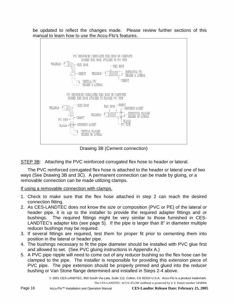
be updated to reflect the changes made. Please review further sections of this manual to learn how to use the Accu-Flo's features.
Drawing 3B (Cement connection)
STEP 3B: Attaching the PVC reinforced corrugated flex hose to header or lateral.
The PVC reinforced corrugated flex hose is attached to the header or lateral one of two ways (See Drawing 3B and 3C). A permanent connection can be made by gluing, or a removable connection can be made utilizing clamps.
If using a removable connection with clamps.
1. Check to make sure that the flex hose attached in step 2 can reach the desired connection fitting.
2. As CES-LANDTEC does not know the size or composition (PVC or PE) of the lateral or header pipe, it is up to the installer to provide the required adapter fittings and or bushings. The required fittings might be very similar to those furnished in CES-LANDTEC's adapter kits (see page 5). If the pipe is larger than 8" in diameter multiple reducer bushings may be required.
3. If several fittings are required, test them for proper fit prior to cementing them into position in the lateral or header pipe.
4. The bushings necessary to fit the pipe diameter should be installed with PVC glue first and allowed to set. (See PVC gluing instructions in Appendix A.)
5. A PVC pipe nipple will need to come out of any reducer bushing so the flex hose can be clamped to the pipe. The installer is responsible for providing this extension piece of PVC pipe. The pipe extension should be properly primed and glued into the reducer bushing or Van Stone flange determined and installed in Steps 2-4 above.

2001 CES-LANDTEC, 850 South Via Lata, Suite 112, Colton, CA 92324 U.S.A. Accu-Flo is a product trademark.
The CES-LANDTEC ACCU-FLOW wellhead is protected by U.S. Patent number 5458006
Accu-Flo™ Installation and Operation Manual CES-Landtec Release Date: February 25, 2005 Page 17
6. Clamps specifically made to fit over the corrugations on the flex hose (power clamps) will be needed to retain the flex hose on the plastic pipe.
7. Slip one of the power clamps over the PVC reinforced corrugated flex hose.8. Next slip the flex hose over the PVC pipe extension installed in step 5 above (see
drawing 3C).9. Using a wrench tighten the hose clamp and do not overtighten. This should secure the
flex hose to the header or lateral.10.You have completed the installation of the Accu-Flo™ wellhead. It is recommended
that the newly installed wellhead be marked with an identification number for reference purposes. It is also suggested that the wellfield log and related well files be updated to reflect the changes made. Please review further sections of this manual to learn how to utilize its features.
If using a permanent connection by gluing.
1. Check to make sure that the flex hose attached in step 2 can reach the desiredconnection fitting.
2. As CES-LANDTEC does not know the size or composition (PVC or PE) of the lateral or header pipe, it is up to the installer to provide the required adapter fittings and or bushings. The required fittings might be very similar to those furnished in CES-LANDTEC's adapter kits (see page 5). If the pipe is larger than 8" in diameter multiple reducer bushings may be required.
3. If several fittings are required, test them for proper fit prior to cementing them into position in the lateral or header pipe.
4. The bushings necessary to fit the pipe diameter should be installed with PVC glue first and allowed to set. (See PVC gluing instructions in Appendix A.)
5. A PVC pipe nipple will need to come out of any reducer bushing so the flex hose can be clamped to the pipe. The installer is responsible for providing this extension piece of PVC pipe. The pipe extension should be properly primed and glued into the reducer bushing or Van Stone flange determined and installed in Steps 2-4 above.
6. Using primer and appropriate PVC solvent cement, cement the flex hose to the header or lateral. (See PVC gluing instructions in Appendix A.) Apply primer and solvent cement to both the PVC reinforced corrugated flex hose and the outside of the nipple described in step 5 above (see drawing 3B).
7. Firmly hold the flex hose on the nipple while the glue dries and sets for several minutes. This should secure the flex hose to the header or lateral.
8. You have completed the installation of the Accu-Flo™ wellhead. It is recommended that the newly installed wellhead be marked with an identification number for reference purposes. It is also suggested that the wellfield log and related well files be updated to reflect the changes made. Please review further sections of this manual to learn how to utilize its features.

2001 CES-LANDTEC, 850 South Via Lata, Suite 112, Colton, CA 92324 U.S.A. Accu-Flo is a product trademark.
The CES-LANDTEC ACCU-FLOW wellhead is protected by U.S. Patent number 5458006
Page 18 Accu-Flo™ Installation and Operation Manual CES-Landtec Release Date: February 25, 2005
Drawing 3C (Clamped connection)
STEP 3C: Attach the composition rubber flex hose to the header or lateral.
See Drawing 3C above.
1. Check to make sure that the flex hose attached in step 2 can reach the desired connection fitting.
2. As CES-LANDTEC does not know the size or composition (PVC or PE) of the lateral or header pipe, it is up to the installer to provide the required adapter fittings and or bushings. The required fittings might be very similar to those furnished in CES-LANDTEC's adapter kits (See page 5). If the pipe is larger than 8" in diameter multiple reducer bushings may be required.
3. If several fittings are required, test them for proper fit prior to cementing them into position in the lateral or header pipe.
4. The bushings necessary to fit the pipe diameter should be installed with PVC glue first and allowed to set. (See PVC gluing instructions in Appendix A.)
5. A PVC pipe nipple will need to come out of any reducer bushing so the flex hose can be clamped to the pipe. The installer is responsible for providing this extension piece of PVC pipe. The pipe extension should be properly primed and glued into the reducer bushing or Van Stone flange determined and installed in Steps 2-4 above.
6. Install the plastic collar ring if purchased with the composition rubber flex hose as described in step 2C 2-4
7. Slip on the stainless steel hose clamp over the flex hose.

2001 CES-LANDTEC, 850 South Via Lata, Suite 112, Colton, CA 92324 U.S.A. Accu-Flo is a product trademark.
The CES-LANDTEC ACCU-FLOW wellhead is protected by U.S. Patent number 5458006
Accu-Flo™ Installation and Operation Manual CES-Landtec Release Date: February 25, 2005 Page 19
8. Next slip the flex hose over the PVC pipe extension and over the collar ring that was glued on in Step 6 above.
9. Using a flathead screwdriver (or hex nut driver), tighten the clamp to secure the flex hose to the header or lateral.
10.You have completed the installation of the Accu-Flo™ wellhead. It is recommended that the newly installed wellhead be marked with an identification number for reference purposes. It is also suggested that the wellfield log and related well files be updated to reflect the changes made. Please review further sections of this manual to learn how to utilize its features.

2001 CES-LANDTEC, 850 South Via Lata, Suite 112, Colton, CA 92324 U.S.A. Accu-Flo is a product trademark.
The CES-LANDTEC ACCU-FLOW wellhead is protected by U.S. Patent number 5458006
Page 20 Accu-Flo™ Installation and Operation Manual CES-Landtec Release Date: February 25, 2005
Field OperationsThis section describes how the Accu-Flo™ wellhead is used to control landfill gas. See
Appendix B for more information on:
how landfill gas is generated
subsurface fires
techniques for controlling LFG
well field monitoring
making adjustments to the well field
adjustment criteria
establishing target flows
well field optimization
LFG migration control
Methods of LFG Control
The Accu-Flo™ Wellhead is a primary tool for the control of landfill gas (LFG) surface emissions, migration and extraction on an open or closed landfill.
The quality and quantity of LFG extracted from the landfill can indicate the overall decomposition rate and "health" of the methane producing organisms in the landfill. If a well in the LFG extraction system draws too much vacuum, air (oxygen) from the surface of the landfill can be pulled into the landfill, killing the methane producing organisms. Thisstops decomposition until the proper oxygen free environment is re-established. The air can also cause sub-surface fires.
Experienced landfill technicians will tell you that each landfill is different. Each well has its own characteristics. Unless the correct data is gathered, it is difficult to maximize LFG collection, control emissions and prevent migration at each well location.
There are four generally accepted ways to control landfill gas extraction:
Control by wellhead vacuum. This method assumes that wellhead vacuum is directly related to the gas extraction rate.
Control by wellhead valve position. Unless the valve handle is pre-calibrated for any given gas flow rate, this method is unpredictable and should not be relied upon.
Control by gas composition. This method measures methane and/or nitrogen (balance gas) concentrations at individual wellheads.
Control by flow rates. This is a more exact method for determining proper gas flow adjustments at individual wells.
Please see Appendix B for additional information about each technique, its benefits and drawbacks.
2001 CES-LANDTEC, 850 South Via Lata, Suite 112, Colton, CA 92324 U.S.A. Accu-Flo is a product trademark.
The CES-LANDTEC ACCU-FLOW wellhead is protected by U.S. Patent number 5458006
Accu-Flo™ Installation and Operation Manual CES-Landtec Release Date: February 25, 2005 Page 21
Well Field Adjustment - Purpose and Objectives
The objective of well field adjustment is to achieve steady state operation of the gas collection system by stabilizing the rate and quality of extracted LFG in order to achieve one or several goals. Typical reasons for recovery of LFG and close control of the well field are:
Achieve and maintain effective subsurface gas migration control.
Achieve and maintain effective surface gas emissions control.
Avoid well over pull and maintain a healthy anaerobic state within the landfill.
Optimize LFG recovery for energy recovery purposes.
Control nuisance LFG odors.
Prevent or control subsurface LFG fires.
Protect structures on and near the landfill.
Meet environmental and regulatory compliance requirements.
Well field adjustment is partly subjective and can be confusing because it involves judgment calls based on simultaneous evaluation of several variables as well as a general knowledge of site-specific field conditions and historical trends. Well field evaluation and adjustment consists of a collection of tools and techniques which may be used in combination to achieve a steady state well field operation.
Taking Measurements at the Accu-Flo™ Wellhead
There are two very different ways to take data measurements at an Accu-Flo™ wellhead: with CES-LANDTEC's integrated GEM-500 or with individual field instruments. Proceed to the appropriate section below depending on the method used.
Using the GEM-500™ to Gather Data
CES-LANDTEC's GEM-500 (Gas Extraction Monitor). This computerized instrument analyzes and records the methane, carbon dioxide and oxygen content of LFG; measures static and impact pressures; as well as gas temperature. It calculates Btu content, Btu flow rate and gas volumetric flow rate. It stores all measured and calculated data from each well which can be downloaded to a personal computer.
The GEM-500 was designed specifically for the landfill gas industry and to be used with Accu-Flo™ Wellheads. The GEM combines many field instruments into one compact instrument which does the following:
Analyzes % Methane (CH4)
Analyzes % Carbon Dioxide (CO2)

2001 CES-LANDTEC, 850 South Via Lata, Suite 112, Colton, CA 92324 U.S.A. Accu-Flo is a product trademark.
The CES-LANDTEC ACCU-FLOW wellhead is protected by U.S. Patent number 5458006
Page 22 Accu-Flo™ Installation and Operation Manual CES-Landtec Release Date: February 25, 2005
Analyzes % Oxygen (O2)
Calculates % Balance Gas (typically Nitrogen)
Measures gas pressure (static and impact)
Measures gas temperature
Calculates gas Btu
Calculates dry gas flow automatically from Accu-Flo™ wellheads
Built-in computer to analyze and store data
Built-in RS232 computer interface to download data to PC
Built-in storage and recall for up to 500 sets of data
These instructions do not go into detail on operating a GEM. Please see the appropriate model GEM Operating Manual for those procedures.
When measuring an Accu-Flo™ Wellhead with a GEM-500:
1. Remove the dust cap from the Accu-Flo™ wellhead. 2. Attach the static and impact pressure quick connect fittings from the GEM to the correct ports on the wellhead. Insert the GEM temperature probe into it’s port. Refer to drawings, shown earlier in this manual, for the location of the connections.
3. Go to the "READ GAS LEVELS MENU" on the GEM-500.4. Answer the next screen's question: "Read Using ID?" 1 - Yes or 2 - No (Note: If
answer is No, gas samples can be taken but flow cannot be calculated without identifying a well's measurement flow device - Accu-Flo™ 150, 200, 300; Orifice Plate or Pitot Tube. See GEM manual for instructions of defining a well ID.)
5. Using the Blue shift key, toggle between numbers and letters to input the Well ID into the GEM.
6. Turn on the GEM's Pump by Pressing KEY 5 until gas samples stabilize (45 - 120 seconds). Turn pump off (press 5) and press 2 - Continue to next screen for Pressure and Temperature .
7. If the temperature probe is not being used, on the Pressure/Temperature Screen enter the temperature by reading the temperature on the Accu-Flo™ Wellhead, and select option 1. Remember to input 3 digits on the GEM. For example, 95 degrees F gas is input as 095 and 125 degree gas as 125.
8. The temperature, Static Pressure (SP) and Differential Pressure (DP) will be displayed on the screen. Disconnect the static and impact hoses from the GEM-500. Select option 2 to zero the transducers, select option 1, press any key to continue, select option 1 to finish the process. Reconnect the hoses and select option 0 to exit.
9. The Flow/BTU Screen appears next. The old (last reading) flow is displayed on the left side of the top line in standard cubic feet per minute (SCFM). The new Btu per cubic foot is displayed on the right side. The new flow is displayed on the second line on the left side in SCFM. On the right side is the Btu's per hour.
10. If adjustments are needed, turn the wellhead valve up or down and the screen will dynamically display the new flow rate and Btu information.

2001 CES-LANDTEC, 850 South Via Lata, Suite 112, Colton, CA 92324 U.S.A. Accu-Flo is a product trademark.
The CES-LANDTEC ACCU-FLOW wellhead is protected by U.S. Patent number 5458006
Accu-Flo™ Installation and Operation Manual CES-Landtec Release Date: February 25, 2005 Page 23
11.To store the information, press 6 and then 0 on the GEM-500. 12.Disconnect the hoses from the Accu-Flo™ wellhead. Press 4 then 1 to continue to
the next ID.13.Replace the dust cap before going to the next well.
Reading the Accu-Flo™ Wellhead - Using Standard Field Instruments
To read the Accu-Flo™ wellhead you will need the following field instruments and equipment:
Digital manometer or Dwyer Magnahelic™ able to read pressure or vacuum in inches of water from approximately 0.0 to 80.0, preferably with multiple scales for greater accuracy between 0.0 to 10.0 inches of water. The manometer must be fitted with tubing and quick connect couplings that mate with the couplings used on the Accu-Flo™ wellhead.
Methane Gas Analyzer
Oxygen Analyzer
Gas extraction pump to overcome wellhead vacuum
Accu-Flo™ Wellhead Flow charts or the Accu-Flo™ hand held calculator (optional)
When measuring an Accu-Flo™ Wellhead with a gage pressure manometer (single hose):
1. Remove the dust cap from the Accu-Flo™ wellhead. 2. Following the manufacture’s instructions, zero the manometer.3. Attach the quick connect fitting on the tubing from the manometer to the static port
(outside port). Measure and record the static pressure. Remove the manometer hose from the wellhead.
4. Attach the quick connect fitting on the tubing from the manometer to the impact port (center port). Measure and record the impact pressure. Remove the manometer hose from the wellhead.
5. The difference between the static and impact pressure is the differential pressure or velocity pressure. It should be a positive number.
6. Read and record the temperature on of the LFG flowing out of the well.7. Connect the vacuum pump to the wellhead, turn on the vacuum pump and extract
LFG samples into a sample bag or LFG container.8. Analyze the LFG samples for methane and oxygen. Record the results.9. Determine and Set Gas Flow Rates in the sections below.10.Replace the dust cap when done.

2001 CES-LANDTEC, 850 South Via Lata, Suite 112, Colton, CA 92324 U.S.A. Accu-Flo is a product trademark.
The CES-LANDTEC ACCU-FLOW wellhead is protected by U.S. Patent number 5458006
Page 24 Accu-Flo™ Installation and Operation Manual CES-Landtec Release Date: February 25, 2005
When measuring an Accu-Flo™ Wellhead with a differential pressure manometer (dual hose):
1. Remove the dust cap from the Accu-Flo™ wellhead.2. Following the manufacture’s instructions, zero the manometer.3. Attach the low side hose from the manometer to the static port (outside port).4. Attach the high side hose from the manometer to the impact port (center port).5. Measure and record the velocity pressure. 6. Disconnect the high side hose from the wellhead. Taking care not to block the end of
the hose, protect the open end of the hose by cupping it in your hand or placing it in your pocket. Measure and record the static pressure.
7. Read and record the temperature on of the LFG flowing out of the well. 8. Connect the vacuum pump to the wellhead, turn on the vacuum pump and extract
LFG samples into a sample bag or LFG container.9. Analyze the LFG samples for methane and oxygen. Record the results.10.Determine and Set Gas Flow Rates in the sections below.11.Replace the dust cap when done.
Determining the Gas Flow Rate
To determine the current gas flow rate (SCFM) of the well, complete the following steps:
1. Use CES-LANDTEC's Flow Charts provided at the end of this manual. You will need to know the Accu-Flo™ wellhead size you are using (1½”, 2” or 3”) and its configuration - either Horizontal or Vertical to properly calculate the flow. There are two charts for each model -- one for wet gas and the other for dry gas. To calculate the amount of heat (Btu's) in the gas, or do other calculations, the gas is usually converted to the amount of dry gas available. The second chart shows the amount of wet or saturated gas at the wellhead.
2. Using the appropriate chart, locate the point where the measured velocity pressure (horizontal axis) intercepts the curve on the chart that best approximates the wellhead temperature.
3. Follow across to the left side of the chart entitled, "Flow" (vertical axis) to determine approximate gas flow rate in standard cubic feet per minute (SCFM).
Note: Static pressure is assumed to be one atmosphere when using CES-LANDTEC's SCFM Flow Charts. CES-LANDTEC's GEM-500 uses actual static pressure to calculate flow.
Setting Gas Flow Rates
To set the gas flow rate (SCFM) for an Accu-Flo™ wellhead, complete the steps below. Refer to the procedures for measuring the velocity pressure and wellhead temperature discussed earlier in this section.
1. Determine the desired gas flow rate (SCFM) for the Accu-Flo™ wellhead.

2001 CES-LANDTEC, 850 South Via Lata, Suite 112, Colton, CA 92324 U.S.A. Accu-Flo is a product trademark.
The CES-LANDTEC ACCU-FLOW wellhead is protected by U.S. Patent number 5458006
Accu-Flo™ Installation and Operation Manual CES-Landtec Release Date: February 25, 2005 Page 25
2. Find CES-LANDTEC's SCFM Flow Chart for the correct size and type Accu-Flo™ wellhead at the end of this manual.
3. Find that flow rate on the vertical axis of the flow graph. Move across the chart to the right until you intercept the curve that best approximates the wellhead gas temperature at the wellhead. Move down the chart and read the velocity pressure on the horizontal axis. This is the velocity pressure that must be obtained to get the desired SCFM rate.
4. Following the procedure under Taking Measurements at an Accu-Flo™ Wellhead, connect the pressure measurement instrument and determine the current velocity pressure.
5. While the pressure measurement instrument is still connected, open or close the valve until the differential (velocity) pressure is obtained that matches the desired SCFM rate.
Other LFG Data
The Accu-Flo™ wellheads pressure and gas sample ports are located for easy access (See drawings on page 2).
These ports are suitable for sampling concentrations of methane, carbon dioxide and oxygen. These measurements can be accomplished through the appropriate ports using portable electronic equipment that are read in the field or by using the same ports to extract gas samples to be analyzed by a laboratory or using a gas chromatograph.
The gas temperature information, when compared with historic readings, can show the presence of a nearby underground fire. Gas samples can be tested for the presence of carbon monoxide which is formed by combustion in the landfill. By removing the impact tube from the wellhead, it can be inspected for soot, which is also another indicator of a nearby underground fire.
Settlement around the well-bore can cause excess oxygen in the LFG, underground fires or surface emissions depending on how the well is being operated.

2001 CES-LANDTEC, 850 South Via Lata, Suite 112, Colton, CA 92324 U.S.A. Accu-Flo is a product trademark.
The CES-LANDTEC ACCU-FLOW wellhead is protected by U.S. Patent number 5458006
Page 26 Accu-Flo™ Installation and Operation Manual CES-Landtec Release Date: February 25, 2005
Accu-Flo™ Wellhead Maintenance ProceduresAccu-Flo™ wellheads are designed to be virtually maintenance free. However,
unforeseen catastrophic events, human error and extreme weather conditions can cause problems.
All Accu-Flo™ Models are virtually the same except for the diameter of the measurement tube assembly and the length of the Impact tube.
Tube Cap, Impact Tube and Pressure Ports Assembly
Drawing 4
Drawing 4 shows how the flow plug, impact tube and pressure ports can be disassembled. The following provides more details:
1. Static Pressure Port: Consists of 1/8" (flow ID) quick connect coupling with automatic shutoff and latching mechanism. It is screwed into the flow plug to create the Static Pressure Port.Recommended Maintenance: Periodically lubricate the O-ring with a light coating of vacuum grease and inspect coupling for corrosion or brittleness caused by extreme weather conditions and UV damage. Replace O-ring or coupling as necessary.
2. Impact Pressure Port: This pressure port has a 1/8" (flow ID) quick connect coupling with automatic shutoff and latching mechanism. It is screwed into the

2001 CES-LANDTEC, 850 South Via Lata, Suite 112, Colton, CA 92324 U.S.A. Accu-Flo is a product trademark.
The CES-LANDTEC ACCU-FLOW wellhead is protected by U.S. Patent number 5458006
Accu-Flo™ Installation and Operation Manual CES-Landtec Release Date: February 25, 2005 Page 27
center of the flow plug. The impact tube is connected to the same port on the underside of the plug.Recommended Maintenance: Periodically lubricate the O-ring with a light coating of vacuum grease and inspect coupling for corrosion or brittleness caused by extreme weather conditions and UV damage. Replace O-ring or coupling as necessary.
3. Thermometer Port: The thermometer port has two configurations. Both use a 1/8" (flow ID) quick connect straight through coupling with automatic latching mechanism. The first configuration has the quick connect screwed directly into the flow plug. The port is plugged with a thermometer assembly or a blank plug. In the second configuration a labcock valve used to shutoff the port. The thermometer port is 180° from the static pressure port.Recommended Maintenance: Periodically lubricate the o-ring with a light coating of vacuum grease and inspect coupling and labcock valve for corrosion or brittleness caused by extreme weather conditions and UV damage. Replace O-ring, coupling or labcock valve as necessary.
4. Thermometer Assembly: The thermometer is mounted on a quick coupling insert. The thermometer has a range of 0 to 220 degrees Fahrenheit.Recommended Maintenance: Verify thermometer calibration, if suspect, using a known temperature standard. The thermometer can be calibrated. Periodically lubricate the O-ring with a light coating of vacuum grease. Replace O-ring as necessary.
5. Flow Plug: The plug above the measurement tube that contains the static, impact pressure and thermometer ports. The impact tube is mounted on the underside of the plug below the impact port. The horizontal wellhead has two plugs. One plug in a horizontal position that contains the impact tube and impact pressure port and a second plug in a vertical position that contains the thermometer and static pressure ports. The plug is sealed with an O-ring and retained by two screws.Recommended Maintenance: To remove the plug and provide access to the impact tube: First mark the orientation of the plug in the tee, then remove the two retaining screws and lift the plug out of the tee using a rotating motion. Before reassembling the plug into the tee, lubricate the O-ring with a light coating of vacuum grease. Replace O-ring as necessary.
6. Impact Tube: The stainless steel impact tube is housed inside of the measurement tube assembly and affixed to the underside of the flow plug with a tube fitting. A guide stabilizes and positions the tube inside the measurement tube.Recommended Maintenance: Traces of smoke residue have been noted on impact tubes in wells that had nearby landfill fires. Otherwise there is little build up on the stainless steel tube. To disassemble the impact tube, remove the flow plug and then unscrew the retaining nut. Take care not to lose the retaining washer or the seal behind the retaining nut. Reverse this step when replacing the impact tube. Lubricate the seal with a light coating of vacuum grease.
7. Dust Cap: The elastomeric PVC dust cap and wire cord are located at the top of the measurement tube assembly to protect the pressure ports from the weather, dust, and UV Exposure.

2001 CES-LANDTEC, 850 South Via Lata, Suite 112, Colton, CA 92324 U.S.A. Accu-Flo is a product trademark.
The CES-LANDTEC ACCU-FLOW wellhead is protected by U.S. Patent number 5458006
Page 28 Accu-Flo™ Installation and Operation Manual CES-Landtec Release Date: February 25, 2005
Recommended Maintenance: Periodically wipe accumulated moisture and dust from the inside of the cap. Replace dust cap if it becomes brittle or cracked.
Flow Control Gate Valve and Gas Sampling Port
Drawing 5
1. Union Disconnect Connector: One side of the union end connector is welded onto the gate valve while the companion union end connector and union nut is welded onto the measurement tube assembly tee.Recommended Maintenance: If necessary to disassemble for any reason inspect O-ring for damage and lubricate with a light coating of vacuum grease.
2. Flow Control Gate Valve: This non-rising stem gate valve provides controlled throttle of gas flow and positive shut-off.Recommended Maintenance: To remove the bonnet, use a box end wrench. The gate valve can be taken apart like any valve and the inner parts can be inspected. Do not over tighten when reassembling as the valve cap can crack.
3. Gas Sampling Port: This port consists of a 1/8" quick connect coupling which is located on the Flow Control Gate Valve Assembly; and is in an ideal location for taking a gas sample. A single cap is provided to keep this port free from dust.Recommended Maintenance: Periodically lubricate the O-ring with a light coating of vacuum grease and inspect coupling for corrosion or brittleness caused by extreme weather conditions and UV damage. Replace O-ring or coupling as necessary.

2001 CES-LANDTEC, 850 South Via Lata, Suite 112, Colton, CA 92324 U.S.A. Accu-Flo is a product trademark.
The CES-LANDTEC ACCU-FLOW wellhead is protected by U.S. Patent number 5458006
Accu-Flo™ Installation and Operation Manual CES-Landtec Release Date: February 25, 2005 Page 29
PVC Flex Hose
Drawing 6
The drawing above shows the PVC flex hose attached to the wellhead and lateral/header pipe.
Flex Hose: The flex hose is shipped separately and welded to the gate valve during installation using flexible solvent cement.Recommended Maintenance: Repair of a damaged flex hose can be accomplished by using one or more PVC 2" slip x 2" slip coupling(s) to splice and weld two flex hose pieces together using flexible PVC Cement.
Measurement Tube Assembly and PVC Pipe Fittings
The measurement tube assembly of the Accu-Flo™ Wellhead includes a various PVC Schedule 80 pipe fittings that are factory assembled. In most cases, if these parts crack or are damaged, the wellhead should be replaced.
Remember: NEVER SHORTEN OR ALTER THE MEASUREMENT TUBE IN ANY MANNER.

2001 CES-LANDTEC, 850 South Via Lata, Suite 112, Colton, CA 92324 U.S.A. Accu-Flo is a product trademark.
The CES-LANDTEC ACCU-FLOW wellhead is protected by U.S. Patent number 5458006
Page 30 Accu-Flo™ Installation and Operation Manual CES-Landtec Release Date: February 25, 2005
APPENDIX A
SCHEDULE 80 PVC SOLVENT CEMENT INSTRUCTIONSCES-LANDTEC's Accu-Flo™ wellheads are made of schedule 80 PVC and adapter kits
are elastomeric PVC. Solvent cement is the recommended method of welding PVC pipe and PVC flexible hose. These procedures are not meant to supersede instructions you may have received with your brand of primer and solvent cement.
In general, when given a choice, a colored primer/cleaner or PVC cement is preferred over clear products because you can see where it has been applied. There are special PVC solvent cements for different sizes of pipes and fittings, conditions and uses. The same is true for primers/cleaners. Match the correct product to the application.
A special cement is required for PVC flexible hose applications. When gluing flex hose to connectors, make sure the proper cement is selected. This glue and primer is not effective for joining other types of piping materials in kind, or to PVC; transition fittings are required.
How It Works
Detailed step by step procedures on how to make good solvent cemented joints are given below. However, we feel that knowing the principles of solvent cementing will help facilitate better quality installation of Accu-Flo™ wellheads at your landfill gas collection system.
Primer is used to wet, penetrate and soften the surface area of the pipe and fitting to be joined, followed by a generous application of cement that is applied to both surfaces. If the cement coatings on the pipe and fitting are wet and fluid, when forcibly joined, they will fuse together. As the cement dissipates, sets and cures, the cement layer and softened surfaces will harden with a corresponding increase in joint strength. A good joint will take the required pressure applicable to landfill wellhead vacuum operation long before the joint is fully dry and final strength is obtained.
The Gluing Environment
Extremes in temperatures are not conducive to good solvent cementing. Avoid solvent cementing in hot weather in excess of 110° and cold weather of 40° or below. For chronically wet conditions, such as the repair of existing piping that contains moisture from gas condensate, use PVC primer and Cement rated for application under wet conditions.
Primers/Cleaners
In general primers are typically purple in color and are for PVC and CPVC applications. The function of a primer is to penetrate and soften the bonding surfaces of pipe and fittings to prepare them for solvent cementing. Use the primer within 3 years of the date stamped on the can. The product should meet ASTM F-656.
Before the primer is used, the pipe, and fittings should be prepared with a square cut, deburred, cleaned and checked for proper fit. Read all cautions and warnings on the can and product MSDS (Material Safety Data Sheet).

2001 CES-LANDTEC, 850 South Via Lata, Suite 112, Colton, CA 92324 U.S.A. Accu-Flo is a product trademark.
The CES-LANDTEC ACCU-FLOW wellhead is protected by U.S. Patent number 5458006
Accu-Flo™ Installation and Operation Manual CES-Landtec Release Date: February 25, 2005 Page 31
Step 1 - Apply Primer
1. Cut pipe square. Remove all burrs from both the inside and outside of the pipe.2. Remove dirt, grease, and moisture. A thorough wipe with clean dry rag is usually
sufficient.3. Check for dry fit. For proper interference fit, pipe should go easily into fitting 1/4 to
3/4 of the way.4. Use a suitable applicator. The dauber in some cans may not be the correct size for
the application. In general the applicator should be 1/2 the diameter of the pipe. Apply primer with an adequate size applicator. (See charts below). A dauber, brush top applicator, swab or paint brush may be used. A rag is not recommended, as repeated contact with skin may cause irritation or blistering.
5. Apply primer freely to the socket keeping the surfaces wet and applicator wet and in motion until the entire joining surface is properly softened. Re-dip if necessary. Avoid puddling in socket. Take care to avoid excess primer in bell end pipe.
6. Now apply primer to pipe surface in the same manner equal to the depth of the socket.
7. Apply primer again to the fitting socket. (This second application is especially recommended for bell end pipe and fittings fabricated from pipe stock, for many of them have especially hard inside surfaces.) Avoid puddling.
8. To check penetration, you should be able to scratch or scrape a few thousandths of the primed surface away. Repeated applications to either or both surfaces may be necessary. Weather conditions do affect priming action. In cold weather more time is required for proper penetration.
9. Immediately and while the surfaces are still wet, apply appropriate PVC Solvent Cement as instructed.
PVC Solvent Cement
TYPE/SETTING APPLICATION COLORMedium body,Fast setting
All classes through 6” dia.,Sch. 80 through 3”
Gray
Heavy body,Medium setting
All classes and schedules through 12” dia.,
Gray
Extra heavy body,Slow setting
All classes and schedules through 22” dia.,
Gray
Medium body,Fast setting
For all flex & flex/rigid fittings Incl. Sch. 80 through 3”
Clear

2001 CES-LANDTEC, 850 South Via Lata, Suite 112, Colton, CA 92324 U.S.A. Accu-Flo is a product trademark.
The CES-LANDTEC ACCU-FLOW wellhead is protected by U.S. Patent number 5458006
Page 32 Accu-Flo™ Installation and Operation Manual CES-Landtec Release Date: February 25, 2005
CAUTION: Cements contain highly volatile solvents that evaporate rapidly. Avoid breathing the vapors. If necessary use a fan to keep work area clear of fumes. Avoid skin or eye contact. Do not use near heat, or sparks or open flame. Do not pressure test with compressed air or gas. Severe damage or personal injury could result. Read all warnings on containers and in product MSDS (Materials Safety Data Sheet).
Make sure solvent cement selected is fit for the use intended. The length of time necessary to cure depends on temperature. If product is "jelly-like" do not use it. Use product within 3 years of date stamped on container.
Step 2 - Apply Cement
1. Use a suitable applicator for the cement. The dauber in some cans may not be the correct size for the application. In general the applicator should be 1/2 the diameter of the pipe.
2. Apply primer as directed by product label and instruction above.3. Apply a full even layer of PVC Solvent Cement on the pipe, equal to the depth of
socket. Coat the fitting socket with a medium layer, avoid puddling. On bell end pipe do not coat beyond socket depth or allow cement to run beyond bell. Put a second full even layer on the pipe. Cement layers must be without voids and sufficient to fill any gap in the joint. Larger sizes often require a two person crew.
4. Assemble without delay while cement is still wet. Use sufficient force to ensure that pipe bottoms in the socket. If possible, twist pipe 1/8 to 1/4 turn as you insert but not after cement has started to set. Hold together for about 30 seconds to make sure that pipe is not pushed out. With a rag, wipe off any excess cement. Avoid disturbing the joint. If the setting process is disturbed an improper or "bad" joint may result. Such a joint will not have the proper strength and may fail or leak.
5. Allow about 15 minutes for good handling strength. Cure time before testing depends on size, fit, temperature and pressures. For larger sizes and temperatures below 40° F, longer periods are necessary.
Applicator and Other Material Requirements
Obtain the correct solvent cement and primer applicators. For pipe sizes 2" through 6" in diameter, use a 2" diameter roller applicator or large cotton swab applicator for PVC pipes 6" or larger. The primer applicator is a small brush applicator usually included as part of the primer container cap.
TYPE APPLICATOR USEDauber in small can Is satisfactory for all pipe &
fittings up to 3” in diameter.Large Roller For pipe up to 6” in diameterJumbo Roller or Swab For pipe over 6” in diameter

2001 CES-LANDTEC, 850 South Via Lata, Suite 112, Colton, CA 92324 U.S.A. Accu-Flo is a product trademark.
The CES-LANDTEC ACCU-FLOW wellhead is protected by U.S. Patent number 5458006
Accu-Flo™ Installation and Operation Manual CES-Landtec Release Date: February 25, 2005 Page 33
A dry clean cloth will be required to clean the pipe and fitting surfaces.
Final Warnings - Handling Solvent Cements and Primers
We want to emphasize that solvent cements and primers contain highly volatile solvents, which evaporate rapidly. Utmost care must be taken to avoid personal injury and to keep solvent cements usable.
They are always flammable.
Avoid breathing vapors.
Avoid skin or eye contact.
Keep containers closed when not in use.
Solvent cements are formulated to be used "as received" in the original containers. If cement thickens beyond its original consistency, discard it. Do not attempt to dilute it with thinner.
Solvent cement has a limited shelf life. Discard it if the manufacturer's date is exceeded.

2001 CES-LANDTEC, 850 South Via Lata, Suite 112, Colton, CA 92324 U.S.A. Accu-Flo is a product trademark.
The CES-LANDTEC ACCU-FLOW wellhead is protected by U.S. Patent number 5458006
Page 34 Accu-Flo™ Installation and Operation Manual CES-Landtec Release Date: February 25, 2005
APPENDIX B
Landfill Gas Field Operations
Landfill Gas Generation
While a detailed discussion of the phenomena and theory of methane generation and its recovery is beyond the scope of this appendix, a brief overview will be helpful.
Initially, when decomposable refuse is placed into a municipal solid waste landfill, the refuse is emplaced with air from the surrounding atmosphere. Through a natural process of bacterial decomposition the oxygen from the air is consumed and an anaerobic, (i.e., oxygen free), environment is created within the landfill. This anaerobic environment is one of several conditions necessary for the formation of methane. If oxygen is reintroduced into the landfill, those portions into which the oxygen are introduced are returned to an aerobic, (i.e., oxygen present), state and the methane producing bacteria population is killed off.
Some time must pass before the productive capacity is returned to normal. Since there is some methane (of a given quality) within the landfill void space, a decline in methane quality is only gradually apparent depending upon the size of the landfill, mass and other factors.
Carbon dioxide is also produced under either aerobic or anaerobic conditions. Under static conditions, the landfill gas will be composed of roughly half methane and half carbon dioxide with a little nitrogen.
As air is introduced into the landfill, the oxygen is initially converted to carbon dioxide and a nitrogen residual remains. Measurement of residual nitrogen is usually a good indicator of the anaerobic state of the landfill, however, it cannot be easily directly measured. It can however be assumed and estimated, using a subtraction basis, as the balance gas. Hence, measurement of carbon dioxide is an intermediate step. Because carbon dioxide levels may fluctuate depending on the changing concentrations of the other constituent gases, carbon dioxide levels are not evaluated directly but are considered in light of other data.
In evaluation of residual nitrogen, allowances must be made if there has been any air leakage into the gas collection system or if there has been serious overpull. If enough air is drawn into the landfill, not all oxygen is converted into carbon dioxide and thus the oxygen is apparent in the sample. It is ideal to perform routine analysis of individual wells, as well as an overall well field composite sample, by gas chromatograph. This however is not always practical at every landfill and can be quite time consuming and costly.
Under some conditions there may be a small amount hydrogen in the LFG, (about 1 percent, usually much less), this may affect field monitoring response factors in some instruments, but otherwise can be ignored.

2001 CES-LANDTEC, 850 South Via Lata, Suite 112, Colton, CA 92324 U.S.A. Accu-Flo is a product trademark.
The CES-LANDTEC ACCU-FLOW wellhead is protected by U.S. Patent number 5458006
Accu-Flo™ Installation and Operation Manual CES-Landtec Release Date: February 25, 2005 Page 35
SUBSURFACE FIRES
If very large quantities of air are introduced into the landfill, either through natural occurrence or overly aggressive operation of the LFG system, a partly unsupported subsurface combustion of the buried refuse may be initiated. Subsurface fire situations are difficult to control or extinguish once started, present health and safety hazards, and can be quite costly. Therefore, prevention, by good operation of the collection system and maintenance of the landfill cover is the best course of action. The presence of carbon monoxide is an indicator of poorly supported combustion within the landfill.
Techniques for Controlling Landfill Gas
There are many techniques for controlling landfill gas extraction. These techniques represent tools that are used together to control landfill gas. The Accu-Flo™ is designed to work with all of these techniques. Below is a discussion of the individual techniques, how to use them and their limitations. Reliance on only a few of the techniques discussed can lead to misinterpretation of field data and improper operation of the wellfield. Later we will discuss the best use of these techniques to optimize landfill gas control.
Controlling by Wellhead Valve Position. Unless the valve handle is pre-calibrated for any given flow rate, this method is unreliable and should not be relied upon. The position of the valve handle alone does not provide sufficient information about the wellfield to control it. It is, however, useful to note the relative position of the valve, and essential to know which valves are fully open or closed.
Controlling by Wellhead Vacuum. This technique relies on the relationship of well pressure/vacuum to flow for a given well. Sole reliance upon this method, however, can be misleading. This is because the square root relationship between flow and pressure is difficult to relate to while performing day to day well field adjustment. As decomposition, moisture, and other conditions change, this method shows itself to be inadequate and imprecise.
Controlling by Gas Composition. This method determines methane, nitrogen (balance gas), and other gas composition parameters at well heads and at recovery facilities using portable field instruments and sometimes analytical laboratory equipment. Complete knowledge of gas composition (i.e., major fixed gases: methane, carbon dioxide, oxygen, and nitrogen) is desirable. It is also necessary to check other gas parameters such as carbon monoxide to evaluate the condition of the wellfield fully.
However, reliance on this information solely can lead to improper operation of the wellfield. Indications of excessive extraction often do not show up right away. Sole reliance often leads to a cycle of damage to the methane producing bacteria population then overcorrecting. This cycling of the well and producing area of the landfill is not a good practice, leads to further misinterpretation of the condition of the well field and has a disruptive effect on the operation of the wellfield.
The use of analytical laboratory instrumentation such as a gas chromatograph is a valuable supplementary tool to verify gas composition. This normally requires collection

2001 CES-LANDTEC, 850 South Via Lata, Suite 112, Colton, CA 92324 U.S.A. Accu-Flo is a product trademark.
The CES-LANDTEC ACCU-FLOW wellhead is protected by U.S. Patent number 5458006
Page 36 Accu-Flo™ Installation and Operation Manual CES-Landtec Release Date: February 25, 2005
of samples at the wellhead and analysis at some fixed location where the equipment is located. The drawbacks of relying on this method as a primary means of obtaining information for well field adjustment are time expended, cost, and probably most important, responsiveness to the needs of the wellfield for timely adjustment. This technique usually is very time consuming. The laboratory analysis costs or ownership of the equipment required is also costly. Some analysis is, however, recommended for verification of field readings from time to time. A monthly sample of the composite gas composition at the inlet to the flare/gas recovery facility is recommended.
Controlling by Flow Rate. This is a more exact technique for determining and adjusting gas flow at a individual wells. It requires using a fixed or portable flow measurement device at each wellhead to obtain data needed to calculate volumetric (or mass) flow rates. A flow device simply measures the quantity of a volumetric unit, (e.g., a cubic foot), which passes across a boundary, (i.e., the point of measurement), in a given unit of time. If we use the weight or mass of the substance within the unit volume being measured, we measure the mass flow rate. It is normally convenient to use cubic feet per minute, or per day, as a standard unit of measure for volumetric flow. Mass flow may be cited in pounds of gas per hour. It is important to distinguish between the volumetric quantity of landfill gas and the volumetric quantity of methane extracted from each well and the landfill in total. The two variables are somewhat independent of each other and it is the total quantity of methane extracted which we are interested in. It is possible for the total quantity of landfill gas extracted to increase while the total quantity of methane extracted decreases. To monitor this, we can calculate the quantity of methane extracted, (LFG flow x percent methane) or the quantity of BTUs, (British Thermal Units, a standard measurement unit of heat energy), recovered per hour, (LFG flow x percent methane x BTUs per cubic foot of methane x 60 minutes per hour). It is conventional to measure BTU's per hour as a unit of time. There are approximately 1012 BTUs per cubic foot of pure methane or natural gas, although this figure varies a little among reference texts.
Measuring flow is an essential part of monitoring and adjusting a wellfield. The well should be adjusted until the amount of methane or BTUs (heat energy) recovered is maximized for the long term. A greater amount of methane or energy can usually be recovered over the short term, however, this ultimately leads to diminishing returns. This is eventually seen in stages as increased CO2 and gas temperature and later increased oxygen from well overpull. In time, the methane will also decline. This is a result of a portion of the landfill, usually at the surface, being driven aerobic. This means that in this portion of the landfill the methane producing bacteria have been killed off. Methane producing bacteria cannot live in the presence of any oxygen. As soon as they see oxygen they die. The methane producing capacity of the landfill has been reduced. The pore space in this area that is no longer producing may become filled with landfill gas equilibrating (moving in) from an unaffected producing area, thus leaving the impression that more gas can be recovered from this area, and thus leading the operator to increase well flow.
As can be seen from the discussion, collection of all of the data parameters discussed, (e.g., valve position, wellhead vacuum, gas composition, flow rate, etc.) is important.

2001 CES-LANDTEC, 850 South Via Lata, Suite 112, Colton, CA 92324 U.S.A. Accu-Flo is a product trademark.
The CES-LANDTEC ACCU-FLOW wellhead is protected by U.S. Patent number 5458006
Accu-Flo™ Installation and Operation Manual CES-Landtec Release Date: February 25, 2005 Page 37
WELL FIELD MONITORING
The frequency of landfill gas (LFG) well field monitoring will vary depending upon field requirements and conditions. Normal monitoring frequency for a complete field monitoring session with full field readings will vary from typically once a month to once a week. Well field monitoring should not normally be extended beyond one month. The importance of regular, timely monitoring cannot be overemphasized.
Normally, a complete set of field readings consists of the following:
Name of person taking readings
Date/time of each reading
Methane (CH4)
Oxygen (O2)
Carbon dioxide (CO2)
Balance Gas (primarily nitrogen N2)
Wellhead gas temperature (flowing)
Ambient temperature
Static pressure (Ps) (from GEM-500 or manometer)
Velocity head (P or Pt) (from GEM-500 or pitot tube and manometer)
Wellhead gas flow (from GEM-500 or pitot tube & manometer)
Wellhead adjustment valve position (initial and adjusted)
New wellhead vacuum and flow information after adjustment
Calculate each well's LFG and methane flow and sum total.
Observations/comments.
Additionally carbon monoxide (CO) or hydrogen sulfide (H2S) readings may be taken if problems are suspected.
Supplementary monitoring once to several times a week may be performed using an abbreviated form of field readings.
An abbreviated form of field readings consist of a combination of some or all of the following:
Name of person taking readings
Date/time of each reading
Methane (CH4)
Oxygen (O2)
Wellhead gas temperature (flowing)
Ambient temperature

2001 CES-LANDTEC, 850 South Via Lata, Suite 112, Colton, CA 92324 U.S.A. Accu-Flo is a product trademark.
The CES-LANDTEC ACCU-FLOW wellhead is protected by U.S. Patent number 5458006
Page 38 Accu-Flo™ Installation and Operation Manual CES-Landtec Release Date: February 25, 2005
Static pressure (Ps) (from GEM-500 or manometer)
Velocity head (P or Pt) (from GEM-500 or pitot tube and manometer)
Wellhead gas flow (from GEM-500 or pitot tube and manometer).
Wellhead adjustment valve position (initial and adjusted)
New wellhead vacuum and flow information after adjustment.
Observations/comments
The determination of which readings to include in the abbreviated set is based on field monitoring needs but should be standardized and include as a minimum: methane, oxygen, static pressure at the well head, and valve position with any adjustment.
Line vacuums and optionally gas quality may be taken at key points along the main gas collection header and subordinate branches. This helps to identify locations of poor performance, excessive pressure drop, or leakage.
Perform systematic monitoring of the well field, taking and logging measurements at each wellhead and major branch junction in the collection system.
During monitoring, examine landfill and gas collection system for maintenance issues. Record needed maintenance or unusual conditions. Examples of unusual occurrences or conditions are: unusual settlement or subsidence, signs of subsurface fires, cracks and fissures, liquid ponding, condensate/leachate weeping from side slopes, surface emissions and hot spots, and liquid surging and blockage in the gas collection system.
Field readings should be kept in a chronological log or data base, as well as turned into management on a timely basis
MAKING WELL FIELD ADJUSTMENTS
It is best to make well field adjustments based on measured data and the experience obtained at a given well empirically. It is also best to adjust the well based on flow. A desired well flow should be determined empirically based on experience with that well and some subjective knowledge about conditions at that well. This requires that operating experience and intuition be developed. The LFG operator/field technician soon develops a close personal knowledge of his or her well field.
The well field may be adjusted on the fly, (while the reading set is being taken), or after collection and evaluation of the complete set of data. This will depend on monitoring objectives. It should be realized that adjustment on the fly will affect the entire well field including wells, which have not yet been monitored. Normally, readings will commence at the furthest well from the blower/flare facility.
Sometimes wells are adjusted based on vacuums in lieu of flow data, however, this is not recommended. Because of the square root relationship between flow and pressure, well adjustment by vacuum/pressure can be deceptive. This technique is, however, sometimes used for hasty field balancing or when time is absolutely critical. The flow rate is proportional to the square root of the velocity head, therefore, if in adjusting a well, the

2001 CES-LANDTEC, 850 South Via Lata, Suite 112, Colton, CA 92324 U.S.A. Accu-Flo is a product trademark.
The CES-LANDTEC ACCU-FLOW wellhead is protected by U.S. Patent number 5458006
Accu-Flo™ Installation and Operation Manual CES-Landtec Release Date: February 25, 2005 Page 39
velocity head is increased by a factor of four, (all other things being equal), and then the flow will increase by a factor of two. Note that overall adjustments to the well field LFG extraction are normally made at the blower/flare station inlet suction-throttling valve.
WELL FIELD ADJUSTMENT - CRITERIA
There are several criteria used in well field adjustment. The primary criteria is methane quality. Methane quality is an indicator of the healthy anaerobic state of the landfill and thus proper operation of the LFG collection system. However, a decline in the healthy productive state of the landfill is usually not immediately apparent from methane quality. Because of this we must consider several criteria at once.
The following criteria for well field adjustment are to be considered:
Methane quality (ranging from 46 percent upwards)
The degree to which conditions within the landfill favor methane production. Typical conditions include: pH, temperature, general cover quality, moisture conditions, waste stream characteristics, placement chronology, insulation characteristics, etc.
Oxygen quality (ranging below 1 percent, preferably less then 1/2 percent)
Landfill cover porosity and depth in the proximity of the well
Gas well construction factors including slotting depth and configuration, gravel pack and seal locations and material; backfill material; placement and compaction; pressure and condition of slip joints.
Landfill construction factors including type of fill, size and shape of refuse mass, depth of fill, compaction, leachate control methods
Seasonal, climatic, geographical, and recent weather, or other considerations, including seasonally arid or wet conditions, precipitation, drainage, groundwater
Surrounding topologic and geologic conditions
Proximity of the well to side slopes (within 150 to 200 ft and less may require conservative operation of the well)
Nitrogen (typically 8 to 12 percent and less)
Temperature (between ambient and about 130 degrees F.)
LFG and methane flow from the wellhead
The design of the gas collection system Landfill perimeter gas migration and surface emission control, or energy recovery objectives
Fluctuation in the diurnal cycle of atmospheric pressure.
ESTABLISHING TARGET FLOWS
For a given individual well, a target flow is established which will likely support maintenance of methane and oxygen quality objectives while maximizing the recovery of LFG/methane. Typically small adjustments are made in flow to arrive at, and maintain,
2001 CES-LANDTEC, 850 South Via Lata, Suite 112, Colton, CA 92324 U.S.A. Accu-Flo is a product trademark.
The CES-LANDTEC ACCU-FLOW wellhead is protected by U.S. Patent number 5458006
Page 40 Accu-Flo™ Installation and Operation Manual CES-Landtec Release Date: February 25, 2005
quality objectives. The well must not be allowed to overpull. High well temperatures, (about 130 to 140 degrees F. and greater), are an indication of aerobic activity and thus, well overpull. Again effects may not be immediately apparent.
Well adjustment should be made in as small an increment as possible, preferably an increment of 10 percent of the existing flow or less. There may be obvious conditions when this is not appropriate, such as when first opening up a well, or when serious overpull is recognized. Every effort should be made to make adjustment and operation as smooth as possible. Dramatic adjustments or operating while switching between a high flow mode and a well shutoff mode is to be avoided.
WELL FIELD OPTIMIZATION
Every effort should be made to continuously locate and correct or eliminate conditions, (e.g., gas condensate surging and blockage, settlement, etc.), which inhibit efficient operation of the gas collection system. This will allow well monitoring and adjustment to be significantly more effective.
MIGRATION CONTROL - DEALING WITH POOR METHANE QUALITY
If methane and oxygen quality objectives cannot be maintained at a given well, such as a perimeter migration control well, then an attempt should be made to stabilize the well as closely as is practical, avoiding significant or rapid downtrending of methane or uptrending of oxygen.
It is not uncommon for perimeter migration control wells to be operated at less than 40 percent methane or greater than 1 percent oxygen. It should be recognized that these wells are likely in a zone where some aerobic action is being induced, and that there is some risk of introducing or enhancing the spread of a subsurface fire. Sometimes a judicious compromise is necessary to achieve critical migration control objectives or because existing conditions do not allow otherwise. Such situations should be monitored closely.
CES-LANDTEC Technical Tips
CES-Landfill Control Technologies from time to time produces information of technical interest. Various subjects are covered as Technical Tips. Please call CES-LANDTEC and ask for about the list of available topics.

2001 CES-LANDTEC, 850 South Via Lata, Suite 112, Colton, CA 92324 U.S.A. Accu-Flo is a product trademark.
The CES-LANDTEC ACCU-FLOW wellhead is protected by U.S. Patent number 5458006
Accu-Flo™ Installation and Operation Manual CES-Landtec Release Date: February 25, 2005 Page 41
APPENDIX C
APPENDIX C ACCU-FLO WELLHEAD FLOW CHARTS

Copyright (C) 2005 CES-LANDTEC

Copyright (C) 2005 CES-LANDTEC

Copyright (C) 2005 CES-LANDTEC

Copyright (C) 2005 CES-LANDTEC

Copyright (C) 2005 CES-LANDTEC

Copyright (C) 2005 CES-LANDTEC

Copyright (C) 2005 CES-LANDTEC

Copyright (C) 2005 CES-LANDTEC
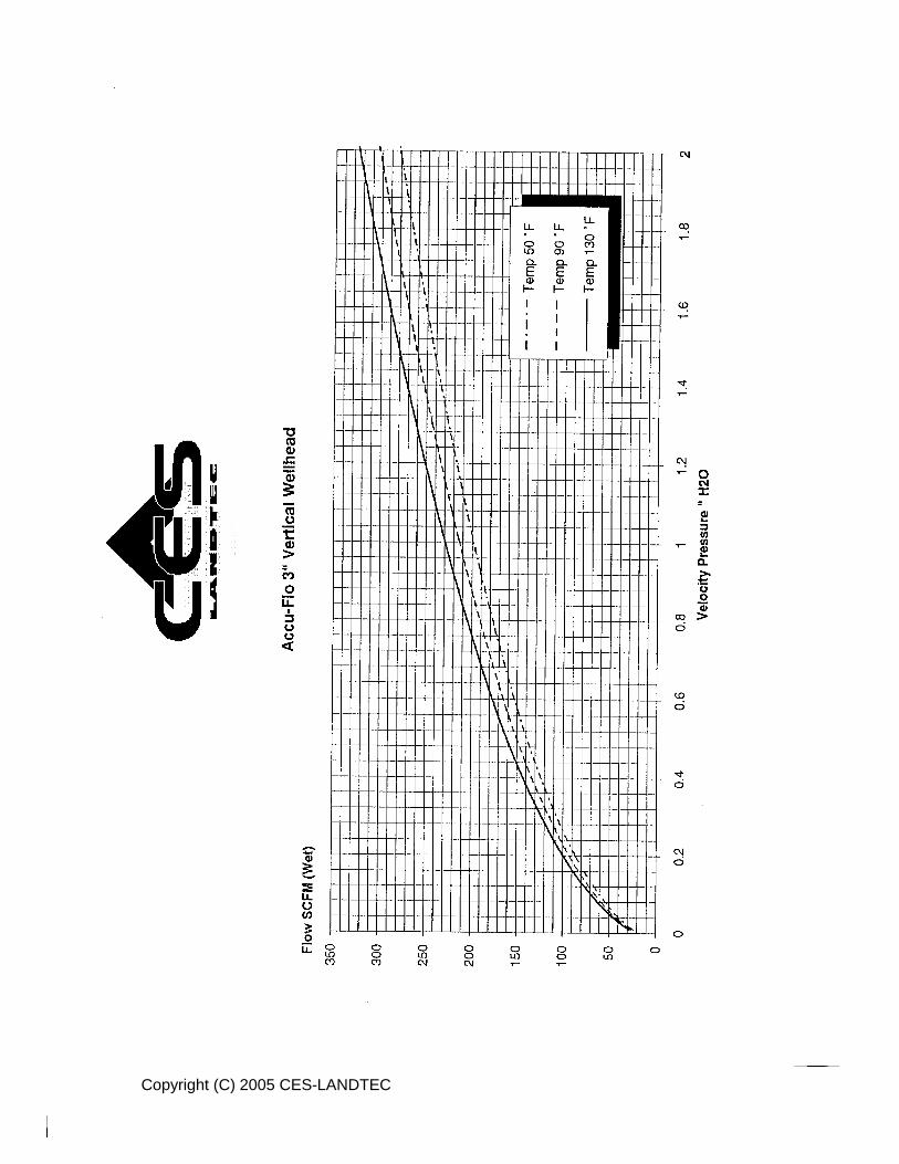
Copyright (C) 2005 CES-LANDTEC

Copyright (C) 2005 CES-LANDTEC
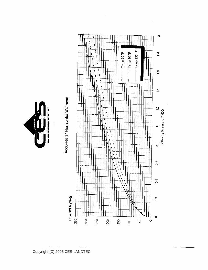
Copyright (C) 2005 CES-LANDTEC

Copyright (C) 2005 CES-LANDTEC

Copyright (C) 2005 CES-LANDTEC

Copyright (C) 2005 CES-LANDTEC

Copyright (C) 2005 CES-LANDTEC

Copyright (C) 2005 CES-LANDTEC

Copyright (C) 2005 CES-LANDTEC

Copyright (C) 2005 CES-LANDTEC

Copyright (C) 2005 CES-LANDTEC

Copyright (C) 2005 CES-LANDTEC

Copyright (C) 2005 CES-LANDTEC

Copyright (C) 2005 CES-LANDTEC

Copyright (C) 2005 CES-LANDTEC

Copyright (C) 2005 CES-LANDTEC