acoustic metamaterials with circular sector cavities and...
TRANSCRIPT

Acoustic metamaterials with circular sector cavitiesand programmable densities
W. Akl and A. ElsabbaghFaculty of Engineering, Ain Shams University, Cairo, 11517, Egypt
A. BazMechanical Engineering Department, University of Maryland, College Park, Maryland 20742
(Received 6 July 2011; revised 23 April 2012; accepted 26 April 2012)
Considerable interest has been devoted to the development of various classes of acoustic metamaterials
that can control the propagation of acoustical wave energy throughout fluid domains. However, all the
currently exerted efforts are focused on studying passive metamaterials with fixed material properties.
In this paper, the emphasis is placed on the development of a class of composite one-dimensional
acoustic metamaterials with effective densities that are programmed to adapt to any prescribed pattern
along the metamaterial. The proposed acoustic metamaterial is composed of a periodic arrangement of
cell structures, in which each cell consists of a circular sector cavity bounded by actively controlled
flexible panels to provide the capability for manipulating the overall effective dynamic density. The
theoretical analysis of this class of multilayered composite active acoustic metamaterials (CAAMM) is
presented and the theoretical predictions are determined for a cascading array of fluid cavities coupled
to flexible piezoelectric active boundaries forming the metamaterial domain with programmable
dynamic density. The stiffness of the piezoelectric boundaries is electrically manipulated to control the
overall density of the individual cells utilizing the strong coupling with the fluid domain and using
direct acoustic pressure feedback. The interaction between the neighboring cells of the composite
metamaterial is modeled using a lumped-parameter approach. Numerical examples are presented to
demonstrate the performance characteristics of the proposed CAAMM and its potential for generating
prescribed spatial and spectral patterns of density variation. VC 2012 Acoustical Society of America.
[http://dx.doi.org/10.1121/1.4744936]
PACS number(s): 43.40.At, 43.40.Fz, 43.50.Fe [ANN] Pages: 2857–2865
I. INTRODUCTION
Metamaterials, either acoustic or electromagnetic, have
recently attracted the focus of many researchers as a new
technique for achieving wave propagation patterns, which
are impossible to realize using regular composite materi-
als.1–3 Developing acoustic or electromagnetic metamateri-
als is physically analogous to engineering periodic material
structure using the inclusions of small inhomogeneities to
enact effective macroscopic behavior.4 Acoustic metamateri-
als are therefore considered as those material structures,
rather than compositions, that are designed and artificially
fabricated to control, guide, and manipulate sound in the
form of sonic, infrasonic, or ultrasonic waves, as these might
occur in gases, liquids, and solids. The hereditary line into
acoustic metamaterials follows from the theory and research
in electromagnetic metamaterials as first developed by Pen-
dry5 who has proven that using negative refractive index
would result in a perfect lens. In 2006, Pendry et al.6 were
the first to present the transformation-based solutions to the
Maxwell’s equations, which have proven to yield a general
method for rendering arbitrarily sized and shaped objects
electromagnetically invisible. This was based on the invari-
ance of the Maxwell’s equations under coordinate transfor-
mation.7,8 Further, with acoustic metamaterials, sonic waves
can now be extended to the negative refraction domain9.
Control of various forms of sonic waves mostly requires
controlling of the bulk modulus B and the density q, which
are counterparts to the electromagnetic permittivity and per-
meability. The speed of sound, on the other hand, being
totally dependent on B and q, is analogous to the refractive
index in electromagnetic domain. It is therefore due to the
analogy to the wave equation in electromagnetic, researchers
have developed the theoretical foundation of acoustic meta-
materials,10,11 where their focus was directed toward various
wave propagation control applications with special interest
in acoustic cloaking rendering objects acoustically invisible.
Several attempts to theoretically and physically control
the bulk modulus and density of different material composi-
tions and structures have been reported, aiming eventually at
controlling the acoustic wave propagation. On the path to
control the bulk modulus, two approaches have been
reported in literature; the first was by combining two differ-
ent isotropic materials in a composite pattern to yield aniso-
tropic properties that can influence the spatial wave
propagation patterns.12–14 In the second mechanism, acoustic
impedance mismatch is introduced along the path of wave
propagation by integrating flexible sections into the rigid-
walled waveguides in order to vary the speed of sound and
effective bulk modulus at these sections.15–17 Manipulation
of the material density, on the other hand, has also been
reported using two different approaches; the first was by
combining two different materials with different densities in
a specific spatial arrangement that would yield a homoge-
nized value of the density all over the domain. Such an
approach was adopted by18–20 using phononic crystals. In
J. Acoust. Soc. Am. 132 (4), Pt. 2, October 2012 VC 2012 Acoustical Society of America 28570001-4966/2012/132(4)/2857/9/$30.00
Redistribution subject to ASA license or copyright; see http://acousticalsociety.org/content/terms. Download to IP: 50.81.134.248 On: Fri, 11 Sep 2015 23:01:24

the second approach, the concept of dynamic density,
which depends on the neighboring material stiffness, was
implemented. This approach was manifested in the attempts
of synthesizing prescribed dynamic acoustic densities in
fluid domains by introducing lattice systems of mass-in-
mass units.21–24 These attempts merely focused on intro-
ducing negative effective density motivated by the mathe-
matical analogy between acoustic and electromagnetic
waves, where the theoretical possibility of having negative
electromagnetic permittivity and permeability was intro-
duced by Pendry.5
In all these studies the focus has been placed on passive
metamaterials with fixed material properties, which has con-
siderably limited the applicability of this new generation of
structured metamaterials in wave propagation control due to
the narrow operating bandwidth in the vicinity of the internal
cell structure resonances. Very few researchers have tackled
the idea of having programmable material properties (bulk
modulus and/or density). Baz25,26 studied the concept of the-
oretically realizing programmable density using a periodic
structure that contains actively controlled piezoelectric ele-
ments coupled with fluid domain to control the effective
dynamic density in the composite structure. Akl and Baz27
have also applied the same concept in controlling the effec-
tive bulk modulus of the composite domain. In their devel-
opment, the authors have, however, limited their model to
straight one-dimensional structures. In this paper, the empha-
sis is placed on the development of a new class of one-
dimensional composite circular sector-type acoustic meta-
materials with tunable effective densities, which can be tai-
lored to have increasing or decreasing variation along the
material volume. Due to the proposed geometry, which is
more oriented toward applications involving cylindrical
domains such as acoustic cloaking for example, the wave
fronts introduced follow the same physics of two-
dimensional circular waves, such as amplitude dependence
on the radial distance from the sound source. Such depend-
ence introduces more complexity in calculating the acoustic-
electrical circuit analogy manifested in the expressions of
the capacitors and inductors representing the fluid domain
compliance and mass, respectively, which to the authors’
knowledge has not been treated yet. A piezoelectric sector
element coupled with a circular sector acoustic cavity is
introduced to form a homogenized periodically structured
sector-shaped acoustic metamaterial. The effective dynamic
density is controlled using the piezoelectric ingredient in the
composite structure. A detailed theoretical analysis is intro-
duced to present a lumped-parameter model of the developed
metamaterial. Acoustic-electrical circuit analogy is used to
model the cavity characteristics, as this approach has proven
to be effective, provided the overall dimensions of the cavity
are much smaller than the wavelengths of the acoustic waves
passing through. A set of cascading “cells” of the developed
metamaterial cell is also introduced showing the capability
of such configuration to control the densities along the path
of the wave propagation. In addition, the necessary precau-
tions to eliminate the instabilities are introduced. These
instabilities occur in the piezoelectric element due to the
active control that might exceed the buckling limit leading
to entire damage in the integrity of the composite metamate-
rial structure.
II. ELECTRIC ANALOGY OF CIRCULAR SECTORACOUSTIC CAVITIES
In order to derive the acoustic-electric circuit analogy to
circular sector acoustic cavities, a brief summary of the
acoustic-electric straight cavity is introduced. Euler and con-
tinuity equations are presented, which are later implemented
in modified form to capture the divergence effect of the cav-
ity cross section on the wave equation in sector acoustic
cavities.
A. Straight cavity
A straight acoustic cavity with uniform cross-sectional
area Ast and length lf, subject to acoustic pressure drop Dpresulting in volumetric flow rate dQ, is considered. The fluid
considered inside the cavity is characterized with static fluid
density qf and bulk modulus Bf. The value of dQ depends on
three major forces; inertia forces due to the mass of the fluid
inside the cavity, elastic forces due to the “stiffness” of the
entrapped fluid volume, and finally friction and damping
forces, which are ignored in the current analysis.
1. Inertia forces
Newton’s second law necessitates that the net force due
to the pressure difference Dp equals the rate of change of
fluid momentum as given by
AstDp ¼ qf lf Ast
dv
dt; (1)
where v is the particle velocity. For a uniform velocity along
the cavity length, dQ=dt ¼ Astðdv=dtÞ, the inertial imped-
ance of the straight cavity after Laplace transformation is
given by
DPðsÞQðsÞ ¼
qf lf
Ast
s ¼ LFs ¼ ZLFðsÞ: (2)
2. Elastic forces
The second type of forces is due to the stiffness of the
fluid domain. A pressure drop of Dp across the cavity will
cause the fluid to be “strained” due to change in its volume
Vol by an amount of d(Vol) such that eV¼�d(Vol)/Vol, and
as the bulk modulus Bf is defined as the difference in pres-
sure, which yields a unit volume strain, Dp¼�Bf d(Vol)/
Vol. The change in volume d(Vol) along a period of time dtis defined as: d(Vol)¼�
ÐQ dt. Hence, and applying Laplace
transformation to Dp, the elastic and total impedance for the
straight acoustic cavity ZCF and Zt are calculated as
ZCFðsÞ ¼DPðsÞQðsÞ ¼
1
CFs¼ 1
s
Bf
Astlf(3)
ZtðsÞ ¼ ZLFðsÞ þ ZCFðsÞ ¼qf lf s
Aþ Bf
Astlf s: (4)
2858 J. Acoust. Soc. Am., Vol. 132, No. 4, Pt. 2, October 2012 Akl et al.: Active acoustic metamaterials
Redistribution subject to ASA license or copyright; see http://acousticalsociety.org/content/terms. Download to IP: 50.81.134.248 On: Fri, 11 Sep 2015 23:01:24

B. Circular sector acoustic cavity
A sector of the fluid domain with point source and
acoustic pressure wave propagating in the radial direction is
as shown in Fig. 1(a). The sector cavity shown, expands
from r¼ r1 to r¼ r2, which includes a central angle c. A slice
of thickness dr is considered for force balance and mass flow
rate calculations.
1. Inertia forces
Considering the infinitesimal slice of thickness dr in the
sector cavity, Newton’s second law necessitates that AðrÞdp¼ qf AðrÞðdv=dtÞdr, where A(r)¼ cHr, H is the cavity depth.
As dQ=dt ¼ AðrÞðdv=dtÞ and integrating (r1! r2), the iner-
tial impedance term is defined as
ZLF ¼DPðsÞQðsÞ ¼ s
qf
Hcln
r2
r1
; (5)
where in the limit case (c ! 0), ZLF reduces to the form for
straight cavity (limc!0ZLFðsÞ ¼ sðqf ðr2 � r1Þ=Hb1Þ), where
b1 is the chord lengths of the inner circular sector.
2. Elastic forces
For sector cavity, a different approach is implemented
in order to calculate the effect of the elastic forces on the
acoustic cavity as follows:ðr2
r1
Fdr ¼ DPE; (6)
where F is the elastic force inside the sector cavity and DPE
is the change in potential energy. Rewriting Eq. (6) such thatÐ r2
r1AðrÞTdr ¼ DpDVol, where A(r) is the cross-sectional
area of the sector cavity at radius r, T is the normal stress,
Dp is the pressure difference across the sector cavity, and
substituting for T with S=SE, where S is the mechanical strain
and sE is the mechanical compliance, dividing by DVol
inside the integral and completing the integration while
replacing 1/sE with fluid bulk modulus Bf results in
Dp ¼ðr2
r1
AðrÞlf Bf
Hcrl2f
dr ¼ DVol Bf
Hcl2fln
r2
r1
(7)
from which the elastic and total impedances ZCF and Zt, as
shown in Fig. 1(b) are calculated as
ZCFðsÞ ¼DPðsÞQðsÞ ¼
1
CFs¼ 1
s
Bf
Hcl2fln
r2
r1
; (8)
ZtðsÞ ¼ ZLFðsÞ þ ZCFðsÞ ¼ sqf
Hcln
r2
r1
þ 1
s
Bf
Hcl2f
lnr2
r1
:
(9)
C. Dynamic density for sector acoustic cavity
Combining both the “inertia” and stiffness impedances
and substituting Bf¼qfc2f, where cf is the speed of sound in
the fluid domain, the dynamic equation for the circular sector
acoustic cavity is given as
Dp ¼ �qf sQ
Hcln
r2
r1
þc2
f
l2f
lnr2
r1
1
s2
!: (10)
For very small cavities, ðr2=r1 ¼ 1þ a; a� 1Þ and defin-
ing Q¼AAve� � and qeff:�Dp=lf ¼ �qeffðdv=dtÞ
�, the rel-
ative density of the acoustic cavity is defined as
qeff
qf
¼ AAve
Hclfln
r2
r1
þAAvec2
f
Hcl3f s2ln
r2
r1
!; (11)
which, for a straight cavity, would converge to the form
given by Baz.25
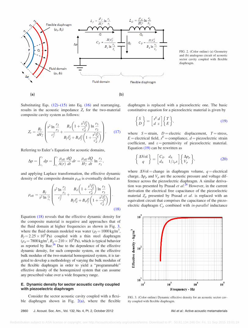
D. Dynamic density for sector acoustic cavity coupledwith flexible diaphragm
Considering a sector acoustic cavity coupled to a flexi-
ble diaphragm as shown in Fig. 2(a) with its analogous
lumped parameter electric circuit shown in Fig. 2(b), the
flexible diaphragm, coupled with the acoustic sector cavity,
represents a composite material that consists of two compo-
nents characterized with different densities (qf, qd), bulk
moduli (Bf, Bd), and thicknesses (lf¼ r2� r1, ld¼ r3� r2) for
the fluid and flexible diaphragms, respectively. Applying
electrical circuit analogy to the acoustic cavity, the overall
circuit impedance (Zt) is calculated by summing up the dif-
ferent impedances representing the different inductors and
capacitors in the circuit as follows:
ZLF ¼ LFs ¼ qf
1
Hcln
r2
r1
s; (12)
ZLD ¼ LDs ¼ qd
1
Hcln
r3
r2
s; (13)
ZCF ¼1
CFs¼ 1
s
Bf
Hcl2f
lnr2
r1
; (14)
ZCD ¼1
CDs¼ 1
s
Bd
Hcl2dln
r3
r2
; (15)
Zt ¼ðZCD þ ZLDÞZCF
ZCD þ ZLD þ ZCFþ ZLF: (16)FIG. 1. (Color online) (a) Geometry of the acoustic sector cavity, (b) electric
circuit analogous to the acoustic sector cavity.
J. Acoust. Soc. Am., Vol. 132, No. 4, Pt. 2, October 2012 Akl et al.: Active acoustic metamaterials 2859
Redistribution subject to ASA license or copyright; see http://acousticalsociety.org/content/terms. Download to IP: 50.81.134.248 On: Fri, 11 Sep 2015 23:01:24
Substituting Eqs. (12)–(15) into Eq. (16) and rearranging,
results in the acoustic impedance Zt for the two-material
composite cavity system as follows:
Zt ¼Bf
sHc
s2 lnr2
r1
c2f
þBd 1þ s2l2
d
c2d
� �ln
r3
r2
Bf l2d þ Bdl2
f 1þ s2l2dc2
d
� �0BBB@
1CCCA: (17)
Referring to Euler’s Equation for acoustic domains,
Dp ¼ðr3
r1
dp ¼ðr3
r1
qeff
AðrÞdQ
dtdr ¼ qeff
HcdQ
dtln
r3
r1
;
and applying Laplace transformation, the effective dynamic
density of the composite domain qeff is eventually defined as
qeff ¼Bf
s2 ln r3
r1
s2 lnr2
r1
c2f
þBd 1þ s2l2
d
c2d
� �ln
r2
r3
Bf l2d þ Bdl2f 1þ s2l2
d
c2d
� �0BBB@
1CCCA:
(18)
Equation (18) reveals that the effective dynamic density for
the composite material is negative and approaches that of
the fluid domain at higher frequencies as shown in Fig. 3,
where the fluid domain modeled was water (qf¼ 1000 kg/m3,
Bf¼ 2.25� 109 Pa) coupled with a thin steel diaphragm
(qd¼ 7800 kg/m3, Bd¼ 210� 109 Pa), which is typical behavior
as reported by Baz.26 Due to the dependence of the effective
dynamic density, for such composite system, on the effective
bulk modulus of the two-material homogenized system, it is tar-
geted to develop a methodology of varying the bulk modulus of
the flexible diaphragm in order to yield a “programmable”
effective density of the homogenized system that can assume
any prescribed value over a wide frequency range.
E. Dynamic density for sector acoustic cavity coupledwith piezoelectric diaphragm
Consider the sector acoustic cavity coupled with a flexi-
ble diaphragm shown in Fig. 2(a), where the flexible
diaphragm is replaced with a piezoelectric one. The basic
constitutive equation for a piezoelectric material is given by
SD
� �¼ sE d
d e
� TE
� �; (19)
where S¼ strain, D¼ electric displacement, T¼ stress,
E¼ electrical field, sE¼ compliance, d¼ piezoelectric strain
coefficient, and e¼ permittivity of piezoelectric material.
Equation (19) can be rewritten as
DVol
q
� �¼ CD dA
dA 1=zps
� Dpp
Vp
� �; (20)
where DVol¼ change in diaphragm volume, q¼ electrical
charge, Dpp and Vp are the acoustic pressure and voltage dif-
ference across the piezoelectric diaphragm. A similar deriva-
tion was presented by Prasad et al.28 However, in the current
derivation the electrical free capacitance of the piezoelectric
material Zp presented by Prasad et al. is replaced with an
equivalent circuit that comprises the capacitance of the piezo-
electric diaphragm Cp combined with in-parallel inductance
FIG. 2. (Color online) (a) Geometry
and (b) analogous circuit of acoustic
sector cavity coupled with flexible
diaphragm.
FIG. 3. (Color online) Dynamic effective density for an acoustic sector cav-
ity coupled with flexible diaphragm.
2860 J. Acoust. Soc. Am., Vol. 132, No. 4, Pt. 2, October 2012 Akl et al.: Active acoustic metamaterials
Redistribution subject to ASA license or copyright; see http://acousticalsociety.org/content/terms. Download to IP: 50.81.134.248 On: Fri, 11 Sep 2015 23:01:24

Lp and in-series capacitance Cs to allow for stability measures
of the active element as will be demonstrated later,
Zp ¼Lps
1þ LpCpCss2
Cp þ Cs
: (21)
1. Calculation of Cp
To calculate the value for Cp, the electric field E across
the piezoelectric sector element must be calculated. Hence, a
Gaussian cylinder of radius r and thickness H is constructed
ðÞ
E dA ¼ EÞ
dAÞ. The ends of the cylinder are normal to the
field and do not contribute to the integral. The only part that
contributes to the electric field is the sector confined by the
angle c, which area is calculated asÞ
dA ¼ crH. As the inte-
gral form of Gauss law is defined asÞ
E dA ¼P
q=e, wherePq (or simply q) is the total charge on the curved sector ele-
ment (q¼ eEcrH), moving a positive test charge between the
sector boundary surfaces, ranging from inner radius r2 to outer
radius r3, requires applied work equal to the change in the
electric potential energy DEPE ¼Ð r3
r2Fdr ¼
Ð r3
r2qEdr ¼ qVp,
where Vp ¼Ð r3
r2ðq=ecrHÞdr ¼ ðq=ecrHÞ ln ðr3=r2Þ, is the
potential difference between the two piezoelectric sector
sides, yielding an expression for Cp ¼ ecH= ln ðr3=r2Þ.
2. Calculation of CD and dA
To calculate the value for CD and dA as in Eq. (20), the
effect of the electric-mechanical coupling in the piezoelectric
materials on the total potential energy stored in the piezoelec-
tric sector element is calculated using Eq. (6), where, F in this
case is the elastic force inside the sector cavity due to both the
mechanical strain and the electrical field and DPE is the change
in potential energy such thatÐ r2
r1AðrÞTdr ¼ DpDVol. Using the
expression for the total stress inside the piezoelectric sector
T¼ (S� dE)/sE extracted from Eq. (19) and replacing sE with
1/Bd (bulk modulus of piezoelectric sector diaphragm), the
acoustic pressure difference across the sector is calculated as
Bd
cHl2d
ðr3
r2
DVol
rdr � cHldd
ðr3
r2
Edr ¼ Dpp: (22)
Integrating Eq. (22) yields an expression for Dpp ¼ ðBd=cHl2dÞDVol lnðr3=r2Þ þ cHlddVp, which can be rearranged to calculate
the values of CD ¼ ðcHl2d=BdÞ ln r3=r2 and dA ¼ dcHld=ln ðr3=r2Þ. The electrical circuit analogous to the coupled fluid-
piezoelectric sector cavities is hence as illustrated in Fig. 4. The
parameter /¼�dA/CD/, also called the transformer turns ratio
in the equivalent circuit representation, is the electroacoustic
transduction coefficient.
Using the piezoelectric diaphragm as a self-sensing ac-
tuator, then the second row of Eq. (20) gives, for a short-
circuit piezosensor, the electric charges in the piezoelectric
diaphragm q¼ dADpp. In which case, the voltage Vp applied
to the diaphragm can be generated by a direct feedback of
the charge q such that Vp¼�GdADpp, where G¼ feedback
gain. Then, the first row of Eq. (20) yields
DVol ¼ ðCD � d2AGÞDpp ¼ CDCDpp; (23)
where CDC¼ closed-loop compliance of the piezoelectric di-
aphragm. Figure 5 displays the corresponding electrical cir-
cuit analogous of the acoustic cavity integrated with a
closed-loop piezoelectric diaphragm characterized with
overall impedance given by
Zt ¼ðZ0p þ ZCDC þ ZLDÞZCF
Z0p þ ZCDC þ ZLD þ ZCFþ ZLF: (24)
Recalling the identities defined in Eqs. (12)–(15), and noting
that Bp ¼ ðHcl2d=CDCÞ ln r3=r2, the total impedance Zt and
the effective density qeff of the coupled composite sector
cavity may be expressed as
Zt ¼Bf ln
r3
r2
Hl2dsZ0pcþ ðBp þ qdl2
ds2Þ ln r3
r2
� �þ s2qf ln
r2
r1
Hl2dl2f sZ0pcþ ðBf l2d þ Bdl2
f þ qdl2dl2f s2Þ ln r3
r2
� �
Hsc Hl2dl2f sZ0pcþ ðBf l2d þ Bdl2f þ qdl2dl2
f s2Þ ln r3
r2
� � ; (25)
qeff ¼Bf ln
r3
r2
�Hl2
dsZ0pcþ ðBp þ qdl2ds2Þ ln r3
r2
þ s2qf lnr2
r1
Hl2dl2
f sZ0pcþ ðBf l2d þ Bdl2
f þ qdl2dl2f s2Þ ln r3
r2
� �
s2 Hl2dl2f sZ0pcþ ðBf l2d þ Bdl2f þ qdl2
dl2f s2Þ ln r3
r2
� �ln
r3
r1
: (26)
FIG. 4. Analogous circuit of an acoustic fluid domain coupled with open-
loop piezoelectric diaphragm.
J. Acoust. Soc. Am., Vol. 132, No. 4, Pt. 2, October 2012 Akl et al.: Active acoustic metamaterials 2861
Redistribution subject to ASA license or copyright; see http://acousticalsociety.org/content/terms. Download to IP: 50.81.134.248 On: Fri, 11 Sep 2015 23:01:24

After rearrangement of Eq. (26), the bulk modulus of the pie-
zodiaphragm Bp and the control gain needed to realize speci-
fied value for qeff can be represented as a frequency
dependent function of Z0p as follows:
Bp ¼ s2l2d
Bf qeff lnr3
r1
� qf lnr2
r1
� �
l2f s2 qf lnr2
r1
� qeff lnr3
r1
� �þ Bf ln
r3
r2
0BB@
�HZ0pc
lnr3
r2
� qd
1CA; (27)
G ¼ Hcl2d
d2A ln
r3
r2
1
Bd� 1
Bp
� �: (28)
A numerical simulation of a sector-shaped composite cavity
using the developed model is developed and the frequency
dependent piezoelectric bulk modulus Bp, feedback control
gain G and resultant effective density qeff for the composite
system for target relative density values (qr¼ qeff/qf¼ 20)
and (qr¼ 0.05) are presented in Fig. 6, which were devel-
oped using the values listed in Table I and specific values of
Cs¼ 5� 10�10 Farad and LP¼ 0.02 H. It is important, how-
ever, to optimize the values of Cs and Lp to obtain the largest
bandwidth with feasible control gain values. Hence, a sensi-
tivity analysis is needed to determine the stability bandwidth
of the piezodiaphragm without reaching a bucking state of
the diaphragm material due to the applied control voltage.
III. CASCADING COMPOSITE CAVITIES WITHVARIOUS PROGRAMMABLE DENSITIES
In the previous section, a single cavity coupled with a
piezoelectric diaphragm was considered. The effective
dynamic density of the composite domain was proven to be
controllable by varying the dynamic bulk modulus of the
piezoelectric diaphragm to yield a frequency-dependent
dynamic density as required. In order to expand the applic-
ability of the introduced methodology, a set of cascading and
coupled composite metamaterial cells are modeled such that
each is programmed to yield different dynamic density
value. This setup is very important in the path to realize
phenomena such as acoustic cloaking, where fluid layers
circumscribing a solid cylinder, for example, can yield the
cloaking phenomenon, provided that their densities and bulk
modulus take a prescribed set of values as demonstrated by
Cheng et al.29. The schematic presentation of the cascading
cavity cells and the corresponding analogous electric circuits
are as shown in Fig. 7.
FIG. 5. Analogous circuit for an acoustic fluid domain coupled with closed-
loop piezoelectric diaphragm.
FIG. 6. (Color online) (a) Bulk modulus of piezodiaphragm, (b) control volt-
age, and (c) relative density for qr¼ 20 and 0.05.
2862 J. Acoust. Soc. Am., Vol. 132, No. 4, Pt. 2, October 2012 Akl et al.: Active acoustic metamaterials
Redistribution subject to ASA license or copyright; see http://acousticalsociety.org/content/terms. Download to IP: 50.81.134.248 On: Fri, 11 Sep 2015 23:01:24

In this system, the last cell represents the cell subject to
external pressure excitation, while the first one is the end of
the chain of the cascading cells. Due to the coupling nature
of the cells, a recursive solution pattern has to be adopted in
order to calculate the different values of the control gains
G(i) needed to alter the effective bulk modulus of the piezo-
electric diaphragms coupled to each cell Bp(i) to ensure a pre-
scribed set of effective densities within the cascading
coupled cells.
The recursive approach starts with the first cell, which is
coupled from one side only to the rest of the metamaterial do-
main. Using the electrical analogy, the overall impedance Z(1)
of this cell can be calculated as a function of the piezoelectric
diaphragm Bulk modulus Bp(1) and the required effective den-
sity qeff(1), as given by Eqs. (27) and (28). Once calculated,
this impedance is shunted to the circuit representing the rest
of the chain. Hence the second cell, loaded with the imped-
ance of the first cell, is now the end of the chain, and is
coupled to the rest of the cells from one side only. Again
using the electrical analogy, the overall impedance Z(2) of the
first two cells can be calculated as a function of the piezoelec-
tric diaphragm bulk modulus Bp(2) and the required density ra-
tio for this cell qeff(2). Following the same logic, the gains G(i)
for the different cells that would yield the prescribed set of
effective density values can be obtained. The impedance of
the ith cell and consequently the effective density and the
bulk modulus of the piezoelectric diaphragm for the ith cell
are hence given by
ZðiÞ¼
Zði�1Þ
�ZCDCðiÞþZ0pðiÞ
�Zði�1ÞþZCDCðiÞþZ0pðiÞ
0@
1AþZLDðiÞ
0@
1AZCFðiÞ
Zði�1Þ
�ZCDCðiÞþZ0pðiÞ
�Zði�1ÞþZCDCðiÞþZ0pðiÞ
0@
1AþZLDðiÞþZCFðiÞ
þZLFðiÞ;
(29)
qeffðiÞ ¼ ZðiÞHc
s lnr3ðiÞrlðiÞ
; (30)
BpðiÞ ¼Bf ln
r3ðiÞr2ðiÞ
Hl2dsZ0pðiÞcþ ðBp þ qdl2ds2Þ ln
r3ðiÞr2ðiÞ
� �þ s2qf ln
r2ðiÞr1ðiÞ
Hl2dl2
f sZ0pðiÞcþ ðBf l2d þ Bdl2
f þ qdl2dl2f s2Þ lnr3ðiÞr2ðiÞ
� �
s2 Hl2dl2f sZ0pðiÞcþ ðBf l2d þ Bdl2f þ qdl2
dl2f s2Þ ln
r3ðiÞr2ðiÞ
� �ln
r3ðiÞr1ðiÞ
:
(31)
The developed model for a system of four cascading cells
has been numerically verified with targeted relative density
values qr¼ 20, 0.05, 12, and 0.15. The frequency-dependent
bulk modulus and corresponding control voltages are as plot-
ted in Fig. 8.
IV. SENSITIVITY ANALYSIS AND PIEZOELECTRICSTABILITY
As mentioned earlier a shunted inductance in-parallelLp and capacitance in-series Cs are added to the piezoelectric
sector element to eliminate the instability that might occur
due to the applied control voltage to achieve the targeted rel-
ative density values. This instability might show up in the
form of negative value of the piezoelectric bulk modulus
indicating a state of buckling. This approach has proven to
be efficient as reported by Akl and Baz.27 However, adding
these two elements introduces an additional pole in the
frequency spectrum of the piezoelectric sector bulk modulus.
It is therefore the objective of this section to study the effect
of the added components on the operating bandwidth of the
newly developed composite acoustic metamaterial. The
expression for the bulk modulus Bp presented in Eq. (27) can
hence be rewritten as
Bp ¼ �qdl2ds2 � ðCp þ CsÞHl2ds2k/2
ðCp þ Cs þ CpCsLps2Þ ln r3
r2
þBf l
2ds2 qf ln
r2
r1
� qef f lnr3
r1
� �
l2f s2 qf ln
r2
r1
� qef f lnr3
r1
� �þ Bf ln
r3
r2
; (32)
which indicates the existence of two singularities; the first is
dependent on the cavity dimensions and properties and the
other is totally dependent on the electric components of the
TABLE 1. Parameters of acoustic cavity/piezodiaphragm system.
Parameter Value
H 0.05 m
c p/36 rad
R1 0.1 m
lf 0.01 m
ld 0.002 m
D �170� 10�12 m/V
qf 1000 kg/m3
qd 7800 kg/m3
Bf 2.25� 109 Pa
Bd 48.31� 109 Pa
er 1750
J. Acoust. Soc. Am., Vol. 132, No. 4, Pt. 2, October 2012 Akl et al.: Active acoustic metamaterials 2863
Redistribution subject to ASA license or copyright; see http://acousticalsociety.org/content/terms. Download to IP: 50.81.134.248 On: Fri, 11 Sep 2015 23:01:24

piezoelectric sector elements combined with the added in-
ductance and capacitance. The singularities (resonant fre-
quencies f1 and f2) occur at
f1 ¼1
2plf
ffiffiffiffiffiffiffiffiffiffiffiffiffiffiffiffiffiffiffiffiffiffiffiffiffiffiffiffiffiffiffiffiffiffiffiffiffiBf ln
r3
r2
qf lnr2
r1
� qeff lnr3
r1
vuuuut ; (33)
f2 ¼1
2p
ffiffiffiffiffiffiffiffiffiffiffiffiffiffiffiffiCp þ Cs
CpCsLp
s: (34)
Figure 9 illustrates a contour plot for the resonance fre-
quency of the electrical components of the acoustic metama-
terial as a function of Cs and Lp. In the design process, this
frequency has to be taken into consideration to select the val-
ues of Cs and Lp connected to Cp to resonate at a frequency
away from the targeted operating bandwidth. However, one
should be cautious reducing the values of Lp and Cs as this
significantly affects the control voltage needed, especially at
lower frequencies. Figure 10 shows the effect of Lp on VP.
Cs has shown no significant effect on the control voltage
needed to achieve a targeted relative density.
V. CONCLUSIONS
A new class of one-dimensional acoustic metamaterial
with controllable density, developed in cylindrical coordi-
nate system is presented. The proposed metamaterial is
designed to take a circular sector shape to allow for coupling
and/or integrating with irregular shaped objects. The effec-
tive density of the composite metamaterial has been theoreti-
cally proven to be controllable and thus any required value
of the effective density can be achieved along a very wide
FIG. 8. (Color online) (a) Piezodiaphragm bulk modulus and (b) control
voltage for four cascading and coupled cells targeting relative density values
qr¼ 20, 0.05, 12, and 0.15.
FIG. 9. (Color online) Electrical components resonance frequency as a func-
tion of Cs and Lp.
FIG. 7. (a) Schematic and (b) analogous circuit for a set of N cascading and coupled cells.
2864 J. Acoust. Soc. Am., Vol. 132, No. 4, Pt. 2, October 2012 Akl et al.: Active acoustic metamaterials
Redistribution subject to ASA license or copyright; see http://acousticalsociety.org/content/terms. Download to IP: 50.81.134.248 On: Fri, 11 Sep 2015 23:01:24

frequency spectrum. The theoretical analysis of this class of
active acoustic metamaterials is presented for an array of
water cavities separated by piezoelectric boundaries using a
lumped-parameter modeling approach. The same model is
also applied for a set of cascading coupled cells. A sensitiv-
ity and stability analysis is conducted to optimize the piezo-
electric electric parameters to prevent the instability that
might occur due to the applied control voltage. A natural
extension of this work is to include active control capabil-
ities to tailor the bulk modulus distribution of the proposed
metamaterial configuration.
ACKNOWLEDGMENTS
This work has been funded by a grant from the Office of
Naval Research (N000140910038). Special thanks are due to
Dr. Kam Ng and Dr. Scott Hassan, the technical monitors,
for their invaluable inputs and comments.
1M. Lapine, “The age of metamaterials,” Metamaterials 1, 1 (2007).2E. Shamonina and L. Solymar, “Matematerials: how the subject started,”
Metamaterials 1, 12–18 (2007).3M. Gil, J. Bonache, and F. Martin, “Metamaterial filters: A review,” Meta-
materials, 2(4), 186–197 (2008).4N. Engheta and R. Ziolkowski, Metamaterials: Physics and EngineeringExplorations (Wiley, New York, 2006), p. 414.
5J. B. Pendry, “Negative refraction makes a perfect lens,” Phys. Rev. Lett.
85(18), 3966–3969 (2000).6J. B. Pendry, D. Schurig, and D. R. Smith, “Controlling electromagnetic
fields,” Science 312(5781), 1780–1782 (2006).
7S. A. Cummer, B. Popa, D. Schurig, D. R. Smith, and J. B. Pendry, “Full-
wave simulations of electromagnetic cloaking structures,” Phys. Rev. E
74, 36621 (2006).8Q. Wu, K. Zhang, F. Meng, and L. Li, “Material parameters characteriza-
tion for arbitrary N- sided regular polygonal invisible cloak,” J. Phys. D
42(3), 35408–35414 (2009).9S. Guenneau, A. Movchan, G. P�etursson, and A. Ramakrishna, “Acoustic
metamaterials for sound focusing and confinement,” New J. Phys. 9(399),
1367–2630 (2007).10S. A. Cummer and D. Schurig, “One path to acoustic cloaking,” New J.
Phys. 9, 45 (2007).11A. N. Norris, “Acoustic cloaking theory,” Proc. R. Soc. London, Ser. A
464(2097), 2411–2434 (2008).12L. Jensen, and C. T. Chan, “Double negative acoustic metamaterial.”
Phys. Rev. E 70(5), 55602 (2004).13Y. Ding, Z. Liu, C. Qiu, and J. Shi, “Metamaterial with simultaneously
negative bulk modulus and mass density,” Phys. Rev. Lett. 99(9), 93904
(2007).14S. H. Lee, C. M. Park, Y. M. Seo, Z. G. Wang, and C. K. Kim, “Acoustic
metamaterial with negative modulus,” J. Phys.: Condens. Matter, 21,
175704 (2009).15S. Choi and Y. Kim, “Sound wave propagation in a membrane-duct,” J.
Acoust. Soc. Am. 112, 1749–1752 (2002).16Y. H. Chiu, L. Cheng, and L. Huang, “Drum-like silencers using magnetic
forces in a pressurized cavity,” J. Sound Vib. 297, 895–915 (2006).17W. Akl and A. Baz, “Configuration of active acoustic metamaterial with
programmable bulk modulus,” Proc. SPIE 7643, 76432K (2010).18F. Cavera, L. Sanchis, J. Perez, R. Sala, C. Rubio, and F. Meseguer,
“Refractive acoustic devices for airborne sound,” Phys. Rev. Lett. 88(2),
23902 (2001).19A. Krokhin, J. Arriaga, and L. Gumen, “Speed of sound in periodic elastic
composites,” Phys. Rev. Lett. 91(26), 264302 (2003).20D. Torrent, and J. Sanchez-Dehesa, “Acoustic metamaterials for new two-
dimensional sonic devices,” New J. Phys. 9, 323 (2007).21C. T. Chan, L. I. Jensen, and K. H. Fung, “On extending the concept
of double negativity to acoustic waves,” J. Zhejiang Univ., Sci. A 7(1),
24–28 (2006).22G. W. Milton and J. R. Willis, “On modifications of Newton’s second law
and linear continuum elastodynamics,” Proc. R. Soc. London, Ser. A
463(2079), 855–880 (2006).23S. Yao, X. Zhou, and G. Hu, “Experimental study on negative effective
mass in a 1D mass- spring system,” New J. Phys. 10, 43020 (2008).24H. Huang, C. Sun, and G. Huang, “On the negative effective mass density
in acoustic metamaterials,” Int. J. Eng. Sci. 47(4), 610–617 (2009).25A. Baz, “An active acoustic metamaterial with tunable effective density,”
J. Vib. Acoust. 132(4), 041011 (2010).26A. Baz, “The structure of an active acoustic metamaterial with tunable
effective density,” New J. Phys. 11, 1230102009 (2009).27W. Akl and A. Baz, “Multi-cell active acoustic metamaterial with pro-
grammable bulk modulus,” J. Intell. Mater. Syst. Struct. 21, 541–556
(2010).28S. A. Prasad, Q. Gallas, S. Horowitz, B. Homeijer, B. V. Sankar, L. N.
Cattafesta, and M. Sheplak, “Analytical electroacoustic model of a piezo-
electric composite circular plate,” AIAA J. 44(10), 2311–2318 (2006).29Y. Cheng, F. Yang, J. Y. Xu, and X. J. Liu, “A multilayer structured
acoustic cloak with homogeneous isotropic materials,” Appl. Phys. Lett.
92, 151913 (2008).
FIG. 10. (Color online) Effect of LP on the control voltage Vp.
J. Acoust. Soc. Am., Vol. 132, No. 4, Pt. 2, October 2012 Akl et al.: Active acoustic metamaterials 2865
Redistribution subject to ASA license or copyright; see http://acousticalsociety.org/content/terms. Download to IP: 50.81.134.248 On: Fri, 11 Sep 2015 23:01:24