acoustic seafloor mapping systems - tu delft ocw · pdf fileacoustic seafloor mapping systems...
TRANSCRIPT

Vermelding onderdeel organisatie
September 14, 2010
1
Acoustic seafloor mapping systems
Delft Institute of Earth Observation and Space Systems
2
Acoustic seafloor mapping techniques
• Single-beam echosounder (since 1920s)
• sidescan sonar (since 1960s)
• multi-beam echosounder (since 1970s)
• …

3
The single-beam echosounder (SBES)
2
ctH
• Signal duration T : ~0.1-1 ms
• Beam width (angular aperture) : ~10
• Frequency f : ~10-500 kHz
• Source level SL : 200-230 dB
4
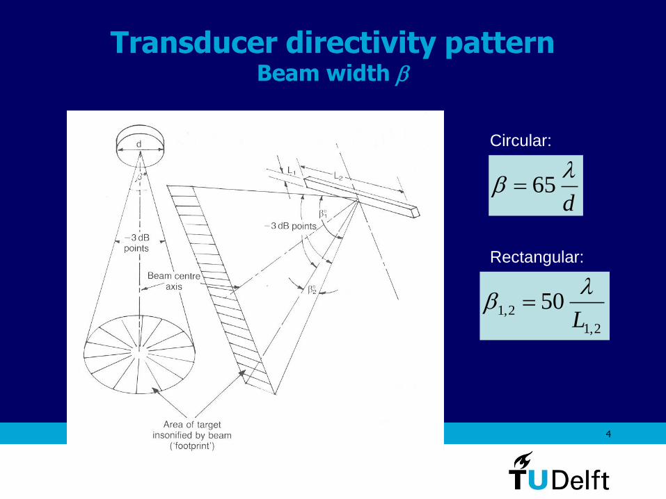
Transducer directivity pattern Beam width
d
65
2,1
2,1 50L
Circular:
Rectangular:

5
Modern digital single beam sounder: effect of frequency choice (38 kHz or 200 kHz)

6
Single-beam echo sounder Transmission sequence
TTc
HTR
2
TTc
nHTR
2
or

7
• Vertical resolution: ,
• Horizontal resolution:
Single-beam echo sounder Measurement resolution
2
cTz
B
cz
2
HHx
2tan2
1)(
2
0
2
0
2
0
2
z
xx
z
z

8
Horizontal resolution shallow water

9
Horizontal resolution - continued shallow water
= 10

10
Horizontal resolution - continued deeper water - same beam width
= 10
11
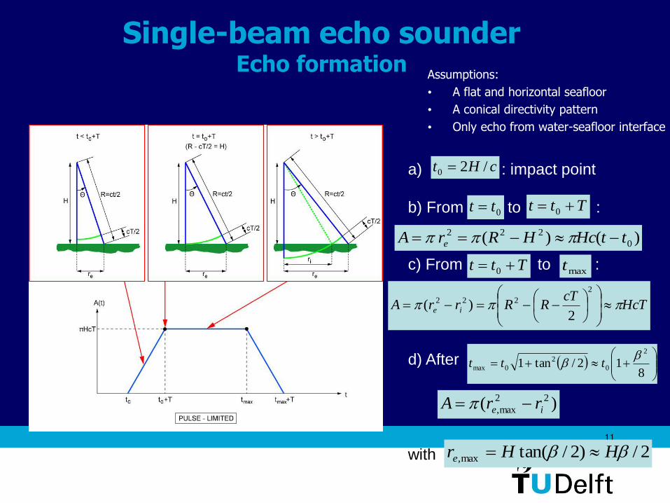
Single-beam echo sounder Echo formation
Assumptions:
• A flat and horizontal seafloor
• A conical directivity pattern
• Only echo from water-seafloor interface
a) : impact point
b) From to :
c) From to :
d) After
with
cHt /20
0tt Ttt 0
)()( 0
222 ttHcHRrA e
Ttt 0
HcTcT
RRrrA ie
2
222
2)(
maxt
812/tan1
2
0
2
0max
ttt
)( 22
max, ie rrA
2/)2/tan(max, HHre

12
Single-beam echo sounder Echo formation, continued
short-pulse or pulse-limited regime:
Ttt 0max
long-pulse or beam-limited regime:
Ttt 0max
Modified expressions for
active area, see lecture notes!
September 14, 2010 13
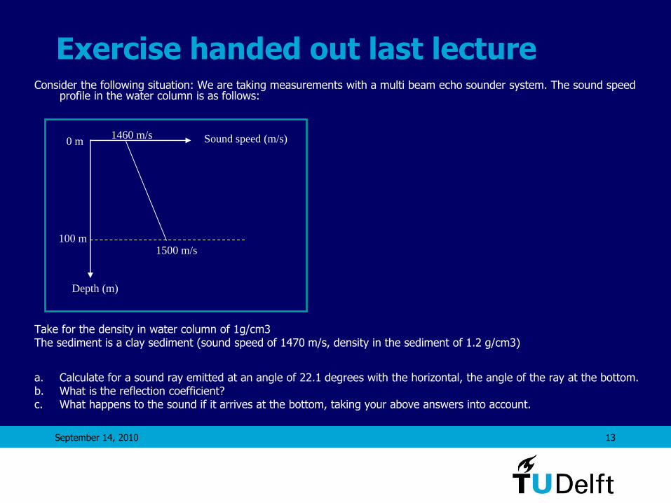
Exercise handed out last lecture Consider the following situation: We are taking measurements with a multi beam echo sounder system. The sound speed
profile in the water column is as follows:
Take for the density in water column of 1g/cm3 The sediment is a clay sediment (sound speed of 1470 m/s, density in the sediment of 1.2 g/cm3)
a. Calculate for a sound ray emitted at an angle of 22.1 degrees with the horizontal, the angle of the ray at the bottom. b. What is the reflection coefficient? c. What happens to the sound if it arrives at the bottom, taking your above answers into account.
0 m
100 m
Depth (m)
Sound speed (m/s) 1460 m/s
1500 m/s

September 14, 2010 14
Exercise handed out last lecture, contn’d
• Step 1: make a sketch of the situation c1 = 1460 m/s, 1 = 1 g/cm3
c2 = 1500 m/s, 1 = 1 g/cm3
c3 = 1470 m/s, 1 = 1.2 g/cm3
1=22.1
2
3
• Step 2: Determine angles
22 1
1
c 1500a cos cos a cos cos 22.1 17.8
c 1460
33 2
2
31
1
c 1470a cos cos a cos cos17.8 21.1
c 1500
c 1470or a cos cos a cos cos 22.1 21.1
c 1460

September 14, 2010 15
Exercise handed out last lecture, contn’d
• Step 3: make a sketch of the reflection coefficient
What is the situation, do we have an angle of intromission or a critical angle? -> The sound speed in the sediment is lower than that in the water column directly above the sediment: no critical angle -> , i.e., we have an angle of intromission
2 2 3 31500 1470 1.2 1764c c x
2
3
2
0 2
3 3
2 2
1
arctan 17.8
1
c
c
c
c

September 14, 2010 16
Exercise handed out last lecture, contn’d
• Step 4: What is the reflection coefficient
Based on the previous analysis we expect a reflection coefficient of 0. Check:
3 3 2 2
3 2
3 3 2 2
3 2
1.2 1470 1500sin sin sin 21.1 sin17.8 0
1.2 1470 1500
sin 21.1 sin17.8sin sin
c c x
Rc xc
September 14, 2010 17
Exercise
• SBES with an opening angle of 10 degrees
• 4000 m of water depth
What is the horizontal resolution?

September 14, 2010 18
2 2
e
4000 10349 m
2 2 180
x=698 m
A= r 0.4 km
e
H x xr
x
Beam footprint

19
Single-beam echo sounder Maximum operating range
• Water depth: 5 km
• Dominant noise source: self noise
• Receiving bandwidth: 500 Hz
• Ship speed: 15 knots
• Echo-sounder: circular transducer with an area of 400 cm2
• SNR should be at least 10 dB
Required specifications for the echo sounder, its frequency f in particular?
20
BGLELSNR
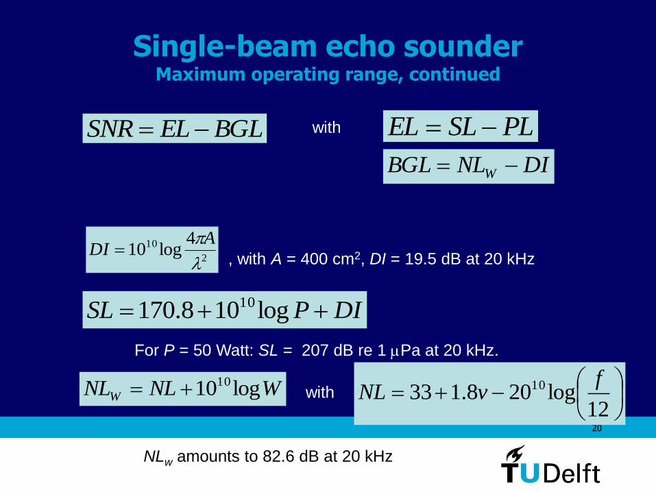
Single-beam echo sounder Maximum operating range, continued
PLSLEL
DINLBGL W
2
10 4log10
ADI
, with A = 400 cm2, DI = 19.5 dB at 20 kHz
DIPSL log108.170 10
For P = 50 Watt: SL = 207 dB re 1 Pa at 20 kHz.
with
12log208.133 10 f
vNLWNLNLW log1010 with
NLw amounts to 82.6 dB at 20 kHz

21
Single-beam echo sounder Maximum operating range, continued
BLHHPL 2)2log(2060 10
is 4.1 dB/km
1122
112210 log20cc
ccBL
Clay : BL = 22 dB
Coarse sand : BL = 7.7 dB

22
Single-beam echo sounder Maximum operating range, continued

23
The sidescan sonar system
beam footprint signal footprint
Footprint:
Transmission sequence:
c
RTR
max2
• Signal duration T : ~less than 0.1 ms
• Beam width (angular aperture) : ~1 in
horizontal plane, ~85 in vertical plane
• Frequency f : several 100 kHz

24
Sidescan sonar Image reconstruction
Measurements consist of backscattered
intensity as a function of time.
For a flat seafloor:
222
22
4H
tcHRy

25
Sidescan sonar Echo formation
Ft
tHh
Obstacle height:
t
tf

26
Sidescan sonar resolution
Across track y
Along
track x
sin2
cTy Across track y:
Along track x: Rx
2/cTy
HcTy
for → 90
for = 0

27
Sidescan sonar coverage
To ensure 100 % coverage:
Hx (insonified strip is narrowest near vertical)
RTvx (sonar distance between two pings)
c
RTR
max2
max
max
cos22
c
R
cHv
(i.e., 100 % coverage condition independent of H)

28
Sidescan sonar Examples
29
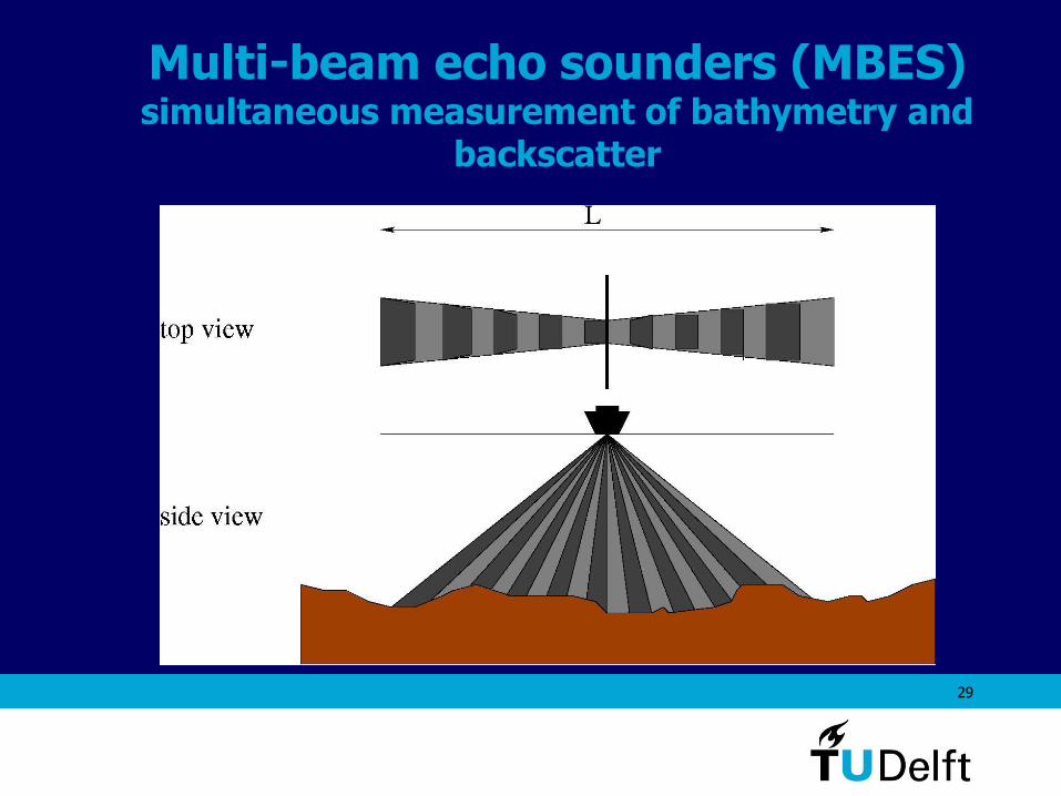
Multi-beam echo sounders (MBES) simultaneous measurement of bathymetry and
backscatter

30
• Deep water systems: operating at f ~ 12 kHz. The large dimensions of the transducer array limits their installation to deep-sea vessels.
• Shallow water systems: operating at f ~ 100-200 kHz. Mapping of the continental shelf.
• High-resolution systems: operating at f ~ 300-500 kHz. Local studies (shipwreck location, inspection of underwater structures). Small size allows for installation on small ships, tow fishes or autonomous underwater vehicles (AUV).
MBES MBES types

31
MBES transmission and reception arrays
Transmission
(determines along-track
resolution x)
Reception (using beamforming)
(determines across track
resolution y)
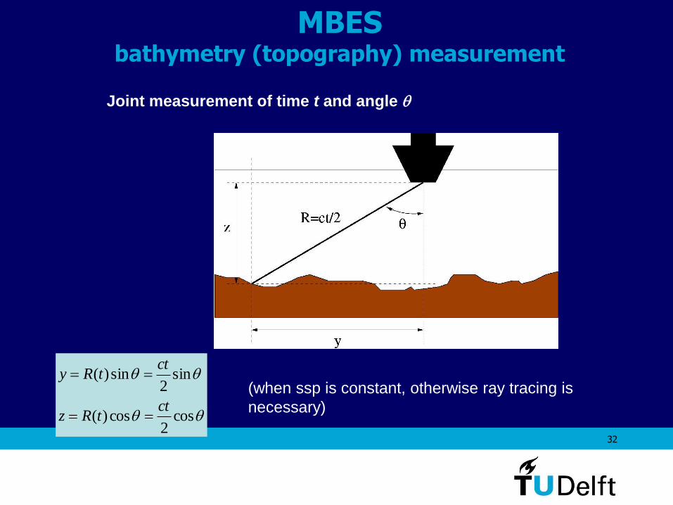
32
MBES bathymetry (topography) measurement
cos2
cos)(
sin2
sin)(
cttRz
cttRy
(when ssp is constant, otherwise ray tracing is
necessary)
Joint measurement of time t and angle

33
MBES imaging
Combining time signals after beamforming:
Compared to SSS:
backscatter pixels are now at the correct position because of bathymetry
measurement capability !!!

34
MBES bathymetry measurement errors
cos2
cos)(
sin2
sin)(
cttRz
cttRy
Errors in range R:
Errors in angle :
sin
cos
Ry
Rz
R
R
HRy
HRz
cos
tansin
Prediction of bathymetry measurement accuracy with MBES
is an important research item !!!
Basis:
Types of errors:
• Errors in the acoustic measurement itself (acoustic noise, non-stable backscattered signal);
• Movements of the support platform (finite accuracy of the attitude sensors);
• Inaccuracies in sound speed corrections.

35
MBES Refraction correction

36
MBES Refraction correction, continued
zgczc 1)( with c(H) = c2
)(zc
dst
gzc
z
zc
z
c
11
1 )(cos
)(
)(coscos Snell’s law:
d
g
cdz
1
1
cos
sin
2
1
2
1
2
2/tan
2
2/tan
ln1
cos
11
cos
sin
sin
1
cos
cos1
1
2
1
11
1
gd
gd
g
c
ct
, with 22 dzdyds and dydz tan sin/dzds :
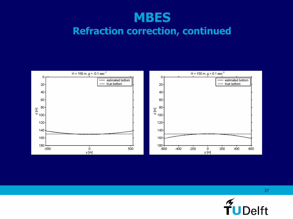
37
MBES Refraction correction, continued

38
MBES resolution
LRx for bathymetry & imaging
sin2
cTy For imaging:
T
Hy
2cosFor bathymetry:
HcTy 0( for )
Along track resolution
Across track resolution
-
sin2
cTy

39
MBES Repetition period and coverage
maxcos2
Lc
v
Global mapping of the deep oceans (H = 4 km)
max = 75, L = 1.5
v: 5 m/s or 10 knots (100 % coverage)
Swathe:
Area covered per second: 13000 km2 per day
Surface of Earth’s deep oceans: 350x106 km2
km30tan2 max HL
sec/km15.0 2vL
Required for global mapping: 2.7x10⁴ days = 74 years
With 50 deep water MBES systems (situation in 2002): ~1 year

40
A typical MBES result