actelec 31 to 800 (bernard) - ksb · actelec 31 to 800 (bernard) 2 production range nominal iso...
TRANSCRIPT

Type series booklet8521.15/2--10 ACTELEC 31 to 800 (BERNARD)
1/4 turn electric actuators(irreversible reducer
with multi--turn electric actuatorACTELEC 31:
screw--nut kinematicsACTELEC 200 to 800:
yoke kinematics
Output torques up to 8000 Nm
General features
The range of ACTELEC series electric actuators developed and manufactured by KSB--AMRI covers output torque values up to8000 Nm.These actuators have been designed for all applications and for the operation of any type¼ turn valves (centredor doubleeccentricdisc valves, ball valves,...).
The mounting interface is in accordance with ISO 5211 standard.Equipped with an interchangeable insert, they can be easily fitted on different valve shaft (square end, flat end, key,...).The actuator is mounted directly or by means of an adaptator onto the valve mounting plate.
This electric actuators range constitued with irreversible kinematics reducer associated with a multi--turn electric actuator is com-pleted by a direct ¼ turn actuators range with irreversible kinematic.
Please consult the type series booklet ACTELEC 3 to 150 ref 8521.12--10.
Protection
They are hose and fine dust proof and are protected against accidental immersion: protection degree IP 67.Motor: insulation class F.
External coating
Reducer: polyurethane paint, thickness 80 µm color dark grey RAL 7016,Electric actuator: polyurethane paint, thickness 80 µm, color blue RAL 5002.
Working temperature range
From --20°C up to +70°C.

ACTELEC 31 to 800 (BERNARD)
2
Production range
Nominal ISO 5211Maximal allowable dimensions for the shaft
TypeNominal
output torquel(Nm)
ISO 5211mounting plate* Height Driving by
squareDriving by flat key
31 1000 ---------- 40 36 36
200 2000 F16 80 60 55Please400 4000 F16 80 60 55 Please,consult us
500 5000 F16 -- F25 95 70 75consult us
800 8000 F16 -- F25 95 70 75
* Direct adaptation onto identical mounting plate.Adaptation by intermediate flange onto different plate (different size or shape).
Construction
Construction and basic equipmentsIn standard version, ACTELEC electric actuators are designed to ensure the on--off function (10 cycles/day), intermittent dutyS4--30 % -- 360 startings / hour in accordance with IEC 34).Remote electric control.
Basic equipments
• Electric motor protection by:-- integrated thermic protection,-- 2 travel limit microswitches (1 microswitch on opening position and 1 on closure position)-- Torque limit system.
• Heating resistance anti--condensation.• Manual emergency control by handwheel.• Position indication.• Mechanical adjustable travel stop(s).
Other constructions
• Motor for continuous duty -- repetitive startings (S4 --50%-- 1200 startings/hour in accordance with IEC 34).• Integral electric control and remote control = INTEGRAL+ version.• Throttling duty with 4--20 mA integrated positioner.
Power supply
• Standard version: 3--phase 400 V -- 50 Hz a.c.
Options on request (please, consult us)
• Additional microswitches adjustable on the whole travel for remote position signalisation (limit position and/or intermediate posi-tion).• Microswitches coupled with torque limiter.• Position transmission by potentiometer 1000 Ω or electronic transmitter 4--20 mA.• Communicatiopn interface -- Intelligence -- Fieldbus.• Other power supplies.• Protection degree: IP 67.• Insulation motor: Class F.

ACTELEC 31 to 800 (BERNARD)
3
ACTELEC31 to 800 actuators are based on a reducerwith irreversible kinematics motorized by amulti--turn electric actuator with amounting plate in accordance with ISO 5210 standard.The mounting interface of these actuators onto the valve is in accordance with ISO 5211 standard.
Manufacturing range -- Characteristics
Actuator Type Basic reducerOutputtorqueNm
InputtorqueNm
Turn number ofthe operating
screw
Electricactuatortype
Actuatormounting plate
ACTELEC 31 M 31 1000 60 32 ASM0
ACTELEC 200 MR 400 2000 60 47 ASM0 ISO 5210ACTELEC 400 MR 400 4000 110 47 ASM1
ISO 5210size F10h B3ACTELEC 500 MR 800 5000 60 135 ASM0 shape B3
ACTELEC 800 MR 800 8000 110 135 ASM1
Operating times
TypeActuator output speed (tr/mn)
Type5 10 17 26 35 51 122
ACTELEC 31 6mn 24s 3mn 12s 1mn 53s 1mn 14s 55s 37s
ACTELEC 200 et 400 9mn 24s 4mn 42s 2mn 46s 1mn 48s 1mn 20s 55s
ACTELEC 500 et 800 7mn 56s 5mn 11s 3mn 51s 2mn 39s 1mn 04s*
* Only ACTELEC 500Other operating times can be realised with a special reducer construction: please consult us.
Characteristics actuator
Electric Actuator
On--Off function3--phase 400 V 50 Hz a.c.Electric
actuatortype
Actuatoroutput speed Motor speed Nominal
PowerNominalintensity
Startingintensity
tr/mn tr/mn kW A A
5 750 0,06 0,6 0,9
10 1500 0,10 0,6 1,2
17 1500 0,10 0,6 1,2
ASM0 26 1500 0,10 0,6 1,2
35 3000 0,14 0,7 2,8
51 3000 0,14 0,7 2,8
122 3000 0,50 1,6 5,0
5 750 0,06 0,6 0,9
10 1500 0,10 0,6 1,2
ASM117 1500 0,10 0,6 1,2
ASM126 1500 0,37 1,1 5,0
35 3000 0,14 0,7 2,8
51 3000 0,50 1,6 5,0

ACTELEC 31 to 800 (BERNARD)
4
On--off function:
ACTELEC 31ASM0
200ASM0
400ASM1
500ASM0
800ASM1
Basic equipments
Opening and closingtorque limit switches
Standard
Mechanical adjustable travel stops Standard on closing position only
Opening and closingtorque limit switches
Standard
Heating resistance Standard
Emergency controlNumber of handwheel turns
32,5 48 138
Power supply 3--phase 400 V a.c.
On/off function S4--30% Yes -- Refer to wiring diagram no. S 50000/04
Other constructions
Continuous duty: S4--50% Yes -- Refer to wiring diagram no. S 50000/04
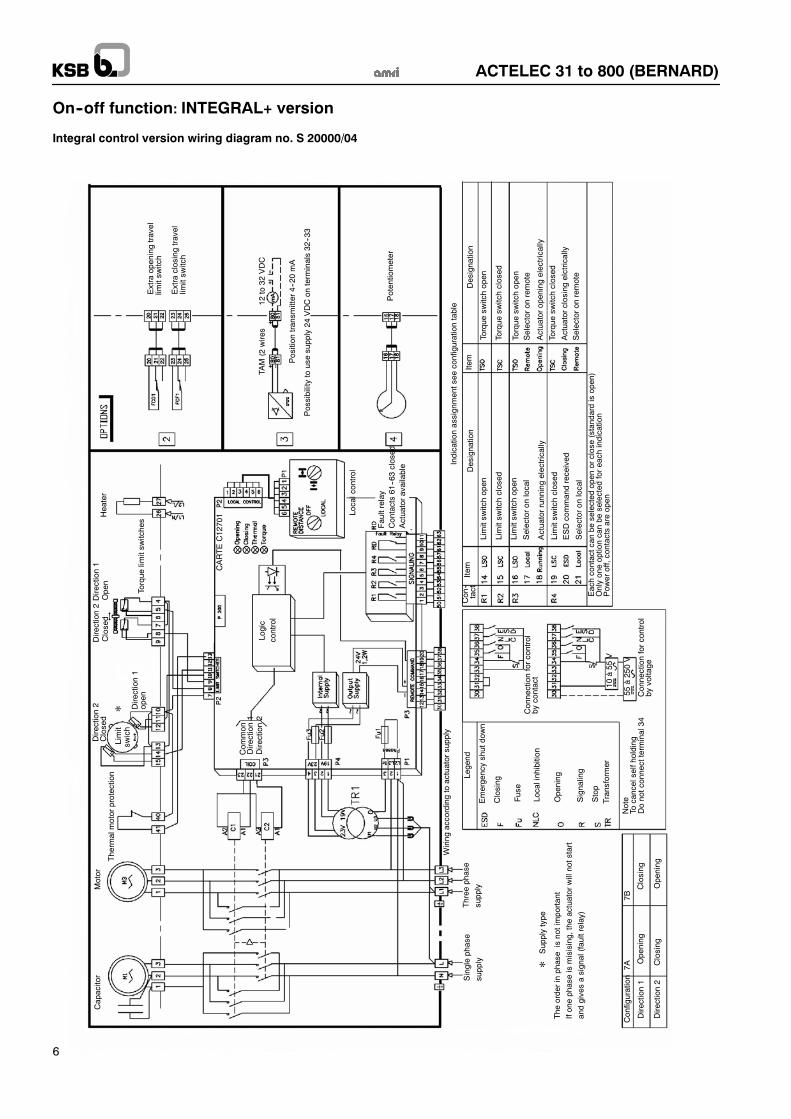
Integral control (INTEGRAL+) Yes -- Refer to wiring diagram no. S 20000/06

ACTELEC 31 to 800 (BERNARD)
5
On--off function: Wiring diagram no. S 50000/04
ACTUATOR WITHTORQUE LIMITINGDEVICE
Motor terminals
(connectionsdetailed below)
Torque limit switchOpen
Torque limit switchClosed
* Torque switches give shortduration contact
* Travel limit switchesgive maintened contact
Travel limit switchOpen
Travel limit switchClosed
Thermal motorprotection
Heater resistance
Direction of rotation seen on opposite side of fixingflange of actuator
POWER SUPPLYMOTORTHREE PHASE
OPTIONAL ACCESSORIES
Extra travel limit switchOpen
Extra travel limit switchClosed
Electronic position transmitter
TAM 4--20 mA 12 to 32 VCC
Potentiometer
ACTELEC 31 to 800 (BERNARD)
6
On--off function: INTEGRAL+ version
Integral control version wiring diagram no. S 20000/04
Capacitor
Motor
Thermalmotorprotection
Direction2
Heater
Configuration
Direction1
Direction2
Opening
Closing
Closing
Opening
Supplytype
The
orderinphaseisnotimportant
Ifonephaseismisising,theactuatorwillnotstart
andgivesasignal(faultrelay)
Emergencyshutdown
Closing
Fuse
Localinhibition
Opening
Signaling
Stop
Transformer
Tocancelselfholding
Note
Donotconnectterminal34
Connectionforcontrol
bycontact
10à55
V
55à250V
Singlephase
supply
Three
phase
supply
Wiring
accordingtoactuatorsupply
Legend
Direction1
Localcontrol
Faultrelay
Contacts61--63closed
Actuatoravailable
Logic
control
CARTEC12701
Extraopeningtravel
limitsw
itch
Extraclosingtravel
limitsw
itch
TAM(2wires
12to32
VDC
Position
transm
itter4--20mA
Possibilitytousesupply24
VDCon
terminals32--33
Potentiometer
Indicationassignmentsee
configurationtable
Item
Item
Con--
tact
Designation
Limitsw
itchopen
Limitsw
itchclosed
Limitsw
itchopen
Limitsw
itchclosed
Selectoron
local
Actuatorrunningelectrically
ESDcommandreceived
Selectoron
local
Designation
Torque
switchopen
Torque
switchclosed
Torque
switchclosed
Torque
switchopen
Selectoron
remote
Actuatoropeningelectrically
Actuatorclosingelctrically
Selectoron
remote
Eachcontactcan
beselected
open
orclose(standardisopen)
Onlyoneoptioncanbe
selected
foreach
indication
Pow
eroff,contactsareopen
Com
mon
Direction1
Direction2
7A7B
Direction2Direction1
Torque
limitsw
itches
Connectionforcontrol
byvoltage
Closed
open
Closed
Open
Limit
swich

ACTELEC 31 to 800 (BERNARD)
7
Throttling duty -- Class III Integral version with positioner 4--20 mAWiring diagram no. S 25000/06
ACTELEC31
ASM0
200
ASM0
400
ASM1
500
ASM0
800
ASM1
Basic equipments
Opening and closingtravel limit switches
Standard
Mechanical adjustable travel stops Standard on closing position only
Opening and closingtorque limit switches
Standard
Heating resistance Standard
Emergency controlNumber of handwheel turns
Please, consult us
Integral control with4--20 mA integrated positioner
Standard
Power supply
3--phase 400 V a.c. Standard

ACTELEC 31 to 800 (BERNARD)
8
Throttling duty -- Class III Integral version with positioner 4--20 mA
Wiring diagram no. S 25000/06
Capacitor
Motor
Thermalmotor
Direction2
heater
Configuration
Direction1
Direction2
Opening
Closing
Closing
Opening
Supplytype
The
orderisnotimportant
Ifonephaseismissing,the
actuatorwill
notstartandgivesasignal(faultrelay)
Emergencyshutdown
Closing
Fuse
CLosedcontact
On/offcontrol
Opening
Signaling
Stop
Transformer
Tocancelselfholding
Note:
Donotconnectterminal34
Connectionforcontrol
bycontact
10to55
V
55to250V
Singlephase
supply
Three
phase
supply
Wiring
accordingtoactuatorsupply
Legend
Direction1
Closed
Limit
switch
Logic
control
C12701CARD
Extraopeningtravel
limitsw
itch
Extraclosingtravel
limitsw
itch
TAM(2wires)
12to32
VDC
Position
transm
itter4--20mA
possibilitytousesupply24
VDCon
terminals32--33
Indicationassignmentsee
configurationtable
Item
Item
Con--
tact
Designation
Limitsw
itchopen
Limitsw
itchclosed
Limitsw
itchopen
Limitsw
itchclosed
Selectoron
local
Actuatorrunningelectrical-
ly ESDcommandreceived
Selectoron
local
Designation
Torque
switchopen
Torque
switchclosed
Torque
switchclosed
Torque
lswitchopen
Selectoron
remote
Actuatoropeningelectrically
Actuatorclosingelectrically
Selectoron
remote
Eachcontactcan
beselected
open
orclose(standardisopen
Onlyoneoptioncanve
selected
foreach
indica-
tion
Pow
eroff,contactsareopen
Com
mon
Direction1
Direction2
Input
signal
4--20mA
0--20m
A(260
ohms)
0--10V
(10kohms)
Potentiometer
Positioner
GAMK
Faultrelay
Contacts61--63
Closed=
Actuator
available
RD
Direction2Direction1
Torque
limitsw
itch
7A7B
Output
signal
4--20mA
0--20m
A(300
ohms
max)
Connectionforcontrol
byvoltage
Open
Closed
Open

ACTELEC 31 to 800 (BERNARD)
9
ACTELEC 31 -- Construction
Section A--A
Electric multi--turn actuator
142
59--40
59--30
59--26
59--35103 20--1
920.4
Item Designation Materials
103 Housing JL 1040 cast iron *
142 Cap Thermodurcissable
20--1 Operating screw Phosphated nickel coated steel
59--26 Connecting rod Steel
59--30 Roller Treated steel + PTFE
59--35 Arm Steel
59--40 Chuck Steel
920.4 Nut Bronze
-------- Electric servomotor housing Cast iron and light alloy
* Anciennes normes : DIN GG 25 / NF FGL 250

ACTELEC 31 to 800 (BERNARD)
10
ACTELEC 200 to 800 -- Construction
Section A--A
ACTELEC 500 and 1600 actuators areequipped with input primary reduction gear.
ACTELEC 200 and 400
ACTELEC 500 and 800
142 81--68 81--68
59--40
176 103 20--1 920.1 160
Electric multi--turn actuator
Item Designation Materials
103 HousingJL 1040 i *142 Cap JL 1040 cast iron*or
160 CoverorJS 1030 ductile iron**
176 BottomJS 1030 ductile iron
20--1 Operating screw Phosphated nickel coated steel
59--40 Chuck + pointer shaft JS 1030 ductile iron** / stainless steel
81--68 Pressure pad Nitrured steel
920.1 Operating nut Bronze
---------- Electric actuator housing Cast iron and light alloy
* Anciennes normes : DIN GG 25 / NF FGL 250** Anciennes normes : DIN GGG 40 / NF FGS 400--15

ACTELEC 31 to 800 (BERNARD)
11
On--off function -- 3--phase supplyOverall dimensions (mm) and weight (kg)
ACTELEC 31View from F
D
E
F
A B
ØC
2 PE M20
F
N
G
H
M
View from F
ACTELEC 200 et 400
DE
F
A B
ØC
2 PE M20
F
N
G
H
Drilling diameter Ød1
n equidistant holes Ød2 M
View from FACTELEC 500 et 800
DE
F
A BF
N
G
H
Drilling diameter Ød1
n equidistant holes Ød2
ØC
2 PE M20
M
ACTELEC Actuator A B ø C D E F G H M NMounting plate ISO 5211 Weight
ACTELEC Actuator A B ø C D E F G H M NRéf ø d1 ø d2 n
Weightkg
31 ASM0 125 401 300 145 65 102 69 152 292 211 -- -- -- -- 42
200 ASM0 229 460 300 208 125 115 95 246 292 211 F16 165 M20 4 72
400 ASM1 229 460 400 208 125 115 95 246 292 211 F16 165 M20 4 74
500 ASM0 271 535 300 245 140 155 109 280 292 211F16 165 M20 4
124500 ASM0 271 535 300 245 140 155 109 280 292 211F25 254 M16 8
124
800 ASM1 271 535 400 245 140 155 109 280 292 211F16 165 M20 4
126800 ASM1 271 535 400 245 140 155 109 280 292 211F25 254 M16 8
126
KSB S.A.S.4, allée des Barbanniers • 92635 Gennevilliers Cedex (France)Tél. : +33 1 41 47 75 00 • Fax : +33 1 41 47 75 10 • www.ksb.com
ACTELEC 31 to 800 (BERNARD)
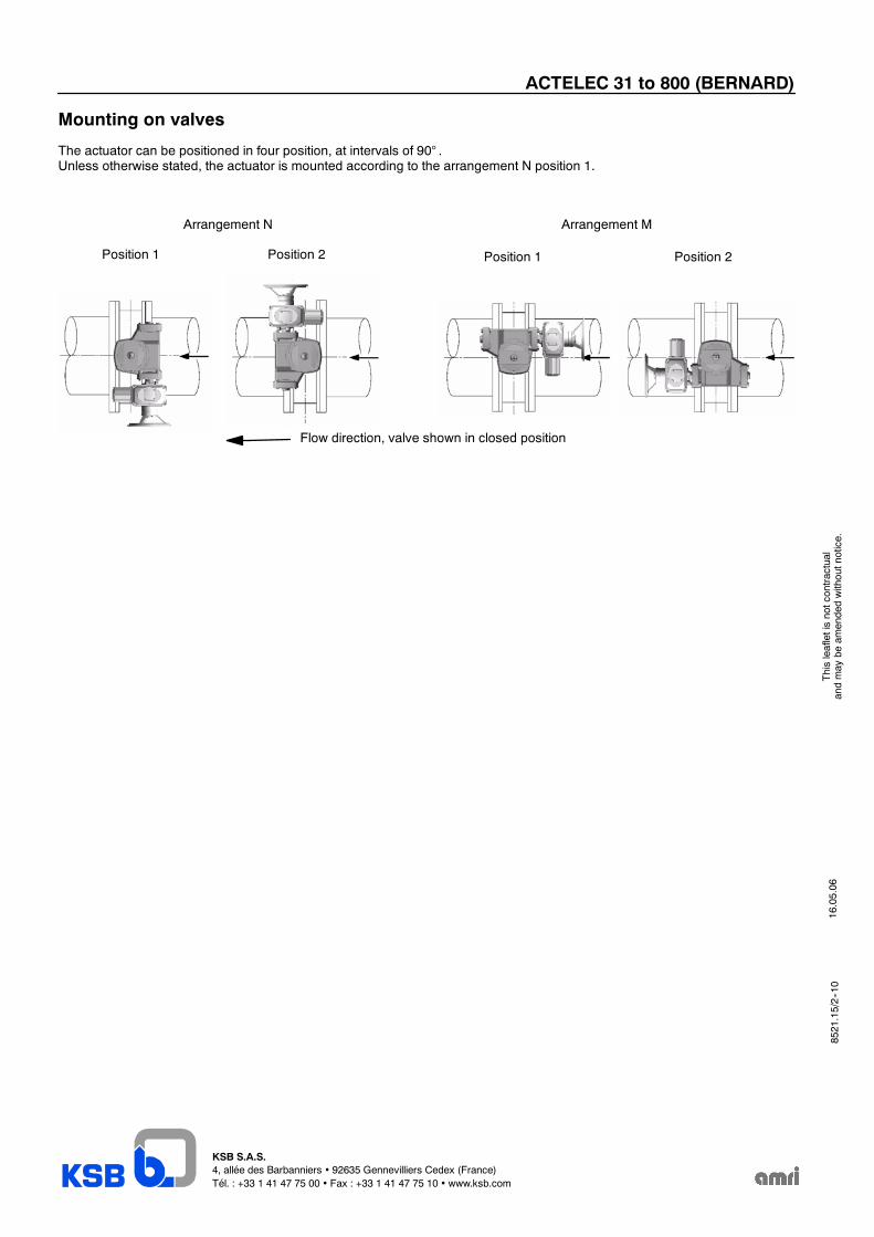
Mounting on valves
The actuator can be positioned in four position, at intervals of 90° .Unless otherwise stated, the actuator is mounted according to the arrangement N position 1.
Arrangement N Arrangement M
Position 1 Position 2 Position 1 Position 2
Flow direction, valve shown in closed position
16.05.06
Thisleafletisnotcontractual
andmay
beam
endedwithoutnotice.
8521.15/2--10