addendum no. 1 - san antonio water system · addendum no. 1 october 11, 2012 this addendum,...
TRANSCRIPT

SAN ANTONIO WATER SYSTEM STEIN TO SALADO INTERCONNECTION DSP PROJECT
JOB # 12-7210 Solicitation No. B-12-060-MR
ADDENDUM NO. 1
October 11, 2012
This addendum, applicable to work designed above, is an amendment to the bidding and specification documents and as such shall be a part of and included in the Contract. Acknowledge receipt of this addendum by entering the addendum number and issue date in the spaces provided on all submitted copies of the bid.
1.0 Bids will not be accepted from any company not represented at the mandatory pre-bid meeting held on October 9, 2012 at 10:00 a.m. The following list is a record of the represented firms.
1. San Antonio Constructors, LTD. 2. Pronto Sandblasting & Coating & Oil Field Services, Co., Inc. 3. Atlas Construction 4. Lewis Contractors 5. Pipelayers, Inc. 6. SAECO Electric and Utility 7. R.L. Jones, LP 8. Pesado Construction 9. Gin-Spen
2.0 MODIFICATIONS TO BID PROPOSAL:
• Remove and replace the bid proposal in its entirety with the attached.
3.0 MODIFICATIONS TO SPECIAL CONDITIONS:
• Remove and replace the Special Conditions in its entirety with the attached.
4.0 MODIFICATIONS TO PLANS:
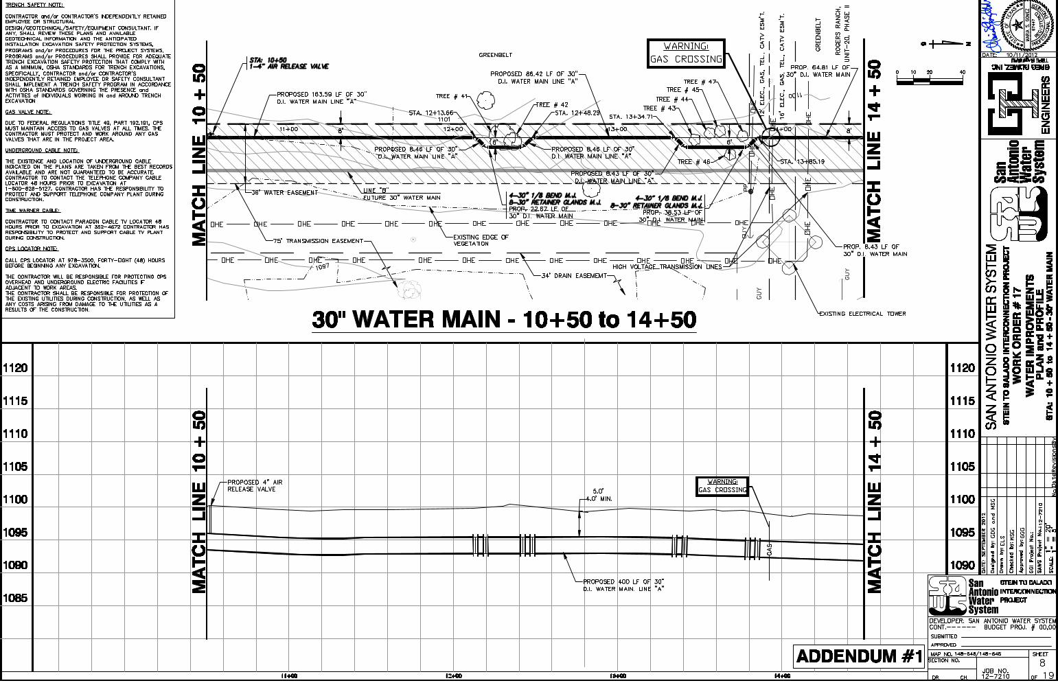
• Sheet 8 of 19 – STA: 10+50: Removed call out for SAWS detail and referenced to plan sheet. • Sheet 11 of 19 – Provided completed Tree Inventory and Preservation Plan • Sheet 14 of 19 – Provided specifications for 24” Steel Water Pipe • Provide final signed and sealed structural plans – sheets 14A and 15A • Provide final signed and sealed electrical plans – sheets E1 to 19.
5.0 MODIFICATIONS TO SPECIFICATIONS:
• Revised Specification 805 – Traffic Control - remove and replace in its entirety • Provide final signed and sealed Bid Item 1050 – Division 16 Electrical Specifications - remove and
replace in its entirety
6.0 RESPONSES TO QUESTIONS:
Q1. What is the size and type of piping/conduit to be installed on this project ? A1. 30” Ductile Iron and 24” Steel Water Main
Addendum No. 1,

Addendum No. 1
Q2. Are there any portions of the project that will need to be bored? A2. No.
Q3. Are they going to be Jack and Bored or Directionally Bored?
A3. There is no jack and bore work. Q4. What are the approximate lengths of the portions to be bored?
A4. There is no jack and bore work. Q5. Is there a Geotechnical Report for the Stein to Salado Interconnect DSP Project. If you have
one, can I please get a copy of it. A5. There is no geotech report.
Q6. Item 844 isn’t that supposed to be a 4” Blow-off ?
A6. No. Q7. Item 507.1 where is this on the plans? And can you provide some details for it.
A7. This item is to be used at the discretion of the SAWS Inspector.
Q8. Item 507.1A need some details of the fence.
A8. To be replaced as per existing wood fence.
Q9. Item 553 should it just be silt fence and what locations.
A9. No, please refer to Specification 553 – Storm Water Pollution Prevention Plan for details.
Q10. Item 805 Traffic Control Plan do we need it for the private road of Huebner?
A10. Traffic Control Plan is needed as per requirements of governing jurisdiction.
Q11. Item 816 24” Steel Water Main. Is that only on the flow meter in precast vault? If not can we
get clarification on were else do we need it? A11. Refer to sheet 14 of 19.
Q12. Item 830 24” Butterfly Valves, we have 8EA does this includes the ones from the 24”
Altitude valve-SCADA?
A12. No.
Q13. Item 1050 Division 16- Electrical, do we include only the flow meter with this item and the electrical?
A13. Section 16930 – Instrumentation is also included in Bid Item 1050, please refer to this section.
Q14. Item 1060 Flow Meter, need specification on what exactly do I need to include in this item.
( 24” steel pipe, bends, etc.) where do we start and where do we finish with this item?
A14. From tie-in to tie-in - to include everything inside the vault except for flow meter and pressure transmitter.
Q15. Item 1070 24” Altitude Valve –SCADA I am assuming for this item to start at 30’ x24” STL. 45
reducer and finish at the 24” DUO Check Valve, or should I include everything all the way up

Addendum No. 1
to the tank connection. And do we need to exclude the butterfly valve out of it and the will be pay in the butterfly valve item?
A15. Yes, up to the check valve, to include bypass. Yes, exclude butterfly valve.
Q16. Item 1080 24” Division Valve – SCADA where do we start and where do we finish? A16. From tie-in to tie-in – to include everything inside the vault.
Q17. Item 836 Pipe Fittings, for this item do I need to only include the fittings that go along the
30” D.I. with the connection to the 24” D.I. pipe. And not include the fittings that go with the flow meter, and the Altitude valve –SCADA, because they are being pay on items 1060, 1080 respectively? Please clarify.
A17. Yes. Q18. Sheet 15 calls for a 24” Duo check valve, however, there’s no bid item nor spec for this
check valve. Please clarify.
A18. Check Valve to be included as part of Bid Item 1070.
Q19. Sheet 8 calls for a 4” air release valve. It references SAWS detail DD-846-02 on plan sheet. However, there’s no air valve detail on sheet 12. Also, the referenced detail is for either a 1” or 2” air valve. Also, there’s no specs for air valves.
A19. This sheet has been revised. Please refer to www.SAWS.org for air valve specifications. Q20. Regarding this project, will there be specifications forthcoming addressing: Butterfly
Valves, Valve Actuator, Steel Pipe. A20. Division Valve Spec: 24” Butterfly, 2.5in stem diameter, 2.790 ft-lbs valve start torque All other butterfly valves should follow specifications as per SAWS Specifications. Valve Actuator: Non Locking, L120-10/5 electric model, gearbox model PTC 30/2/3.5, gearbox ratio
238 Steel Pipe: called out on revised sheet 14 of 19.
Q21. As pertains to Ductile Iron Pipe (sheet 12 of 19, the reference to “Push On” with restraint
gasket), will ALL joints be required to be made with “Field Lok” type gaskets ?
A21. Yes. .
Q22. I need clarification as to bid item 816 – 24” Steel Water Main 127 LF, the 24” line with fittings that is leading to the tank is this what you are pertaining to for this bid item?
A22. Yes.
Q23. Another question is should the Temp Blow off be a 4” as in detail DD-844-04?
A23. No.
Q24. Could you tell me what the 24” Butterfly Valves spec will be for the job?
A24. Please see question No. 20 above.
Q25. The specification calling out for FBE Coating or for the Coal-Tar Coating
A25. All coating as per SAWS Specifications 814 Ductile Iron and 816 Steel Water Main.

7.0 TO PROVIDE OTHER INFORMATION DISCUSSED AT MEETING:
1. Liquidated Damages: $600 Per day after May 14, 2013 escalating to $1,500 Per day after June 30,
2013
2. Contract duration: Fixed Day Contract. Substantial Completion: April 30, 2013, Final Completion: May 14, 2013.
3. We anticipate a November 6, 2012 Board meeting, therefore, the Contract will move very
quickly. 4. Selected contractor shall need to provide statements that reflect number of construction
personnel that will work simultaneously and be assigned to construction tasks. Statement to include personnel available to perform the following work: concrete pad with related valves, bends piping and piping for tank water discharge line. Also number personnel that will be assigned to special construction issues such as vaulted valves, meters and personnel assigned to multiple pipe tie-in task.
10-11-12 ACKNOWLEDGEMENT BY BIDDER
Each bidder is requested to acknowledge receipt of this Addendum No. 1 by his/her signature affixed hereto and to file same and attach with his/her bid.
The undersigned acknowledges receipt of this Addendum No. 1 along with the bid submitted herewith is in accordance with the information and stipulations set forth.
___________________ ____________________________________ Date Signature
END OF ADDENDUM NO. 1 – (4 pages)
Addendum No. 1

Stein to Salado Interconnection Project Job No. 12-7210 Solicitation No. B-12-060-MR ADDENDUM No. 1
7/10/12 BP-1
PROPOSAL PROPOSAL OF , a corporation
a partnership consisting of
and an individual doing business as
TO THE SAN ANTONIO WATER SYSTEM:
Pursuant to Instructions and Invitations to Bidders, the undersigned proposes to furnish all labor and materials as specified and perform the work required for the construction of pipelines and appurtenances, San Antonio Water System Stein to Salado Interconnect Project Job Number 12-7210 in accordance with the Plans and Specifications for the following prices to wit: Item Description Unit Quantity Unit Price Total Price No. (Unit Price to be written in Words) (Figures) (Figures) ____________________________________________________________________________________ 507.1 Chain Link Wire Fence (6’ High)
Dollars and Cents LF 10 ___________ ___________
507.1A Wood Fence
Dollars and Cents LF 10 ___________ ___________
515.1 Topsoil
Dollars and Cents CY 968 ___________ ___________
516.1 Bermuda Sodding
Dollars and Cents SY 5810 ___________ ___________
Job No. 12-7210 Stein to Salado Interconnection Project Solicitation No. B-12-060-MR ADDENDUM No. 1 Item Description Unit Quantity Unit Price Total Price No. (Unit Price to be written in Words) (Figures) (Figures) ____________________________________________________________________________________
7/10/12 BP-2
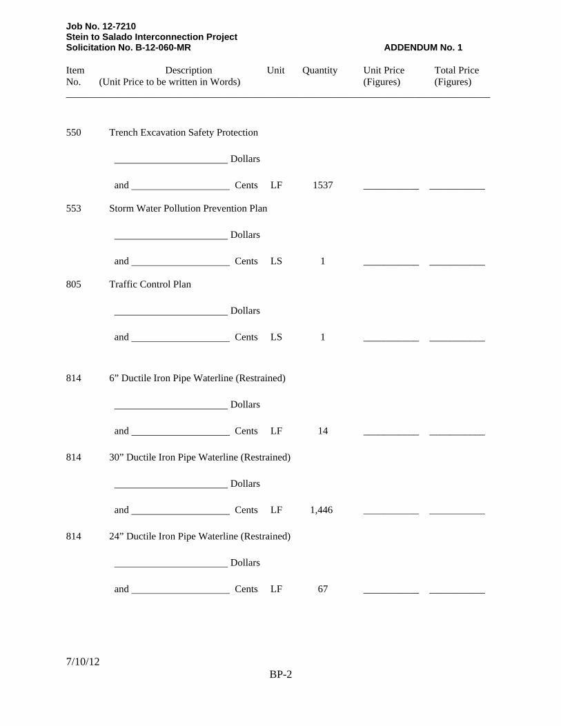
550 Trench Excavation Safety Protection
Dollars and Cents LF 1537 ___________ ___________
553 Storm Water Pollution Prevention Plan
Dollars and Cents LS 1 ___________ ___________
805 Traffic Control Plan
Dollars and Cents LS 1 ___________ ___________
814 6” Ductile Iron Pipe Waterline (Restrained)
Dollars and Cents LF 14 ___________ ___________
814 30” Ductile Iron Pipe Waterline (Restrained)
Dollars and Cents LF 1,446 ___________ ___________
814 24” Ductile Iron Pipe Waterline (Restrained)
Dollars and Cents LF 67 ___________ ___________

Job No. 12-7210 Stein to Salado Interconnection Project Solicitation No. B-12-060-MR ADDENDUM No. 1 Item Description Unit Quantity Unit Price Total Price No. (Unit Price to be written in Words) (Figures) (Figures) ____________________________________________________________________________________
7/10/12 BP-3
816 24” Steel Water Main
Dollars and Cents LF 127 ___________ ___________
828 6” Gate Valve
Dollars and Cents EA 1 ___________ ___________
830 24” Butterfly Valve
Dollars and Cents EA 8 ___________ ___________
831 24”x24” Tee Cut In
Dollars and Cents EA 2 ___________ ___________
834 Fire Hydrant
Dollars and Cents EA 1 ___________ ___________
836 Pipe Fittings, All Sizes & Types
Dollars and Cents TON 16.00 ___________ ___________
844 2" Blow-off, Temporary
Dollars and Cents EA 1 ___________ ___________

Job No. 12-7210 Stein to Salado Interconnection Project Solicitation No. B-12-060-MR ADDENDUM No. 1 Item Description Unit Quantity Unit Price Total Price No. (Unit Price to be written in Words) (Figures) (Figures) ____________________________________________________________________________________
7/10/12 BP-4
846 4” Air Release Valve
Dollars and Cents EA 1 ___________ ___________
1020 24-inch Main Break/Leak Repairs, All Types
Dollars and Cents EA 1 ___________ ___________
1020 30-inch Main Break/Leak Repairs, All Types
Dollars and Cents EA 1 ___________ ___________
1040 Pipe supports and steel braces for top of tank discharge pipe – to include all labor, materials,
tools necessary to complete the work.
Dollars and Cents LS 1 ___________ ___________
1050 Division 16 – Electrical (to include Instrumentation)
Dollars and Cents LS 1 ___________ ___________
1060 Flow meter vault - to include vault piping, tie-in piping to existing 24” and all appurtenances –
complete in place.
Dollars and Cents LS 1 ___________ ___________

Job No. 12-7210 Stein to Salado Interconnection Project Solicitation No. B-12-060-MR ADDENDUM No. 1 Item Description Unit Quantity Unit Price Total Price No. (Unit Price to be written in Words) (Figures) (Figures) ____________________________________________________________________________________
7/10/12 BP-5
1070 24” Altitude valve – SCADA monitored and controlled, complete with foundation pad and pipe supports.
Dollars and Cents LS 1 ___________ ___________
1080 24” Division Valve – SCADA monitored and controlled, install and put into operation one solenoid control valve in vault to include vault piping, tie-in piping, all appurtenances – complete in place.
Dollars and Cents LS 1 ___________ ___________
Bid Summary
LINE ITEM “A” SUBTOTAL BASE BID (WATER) $ 100 MOBILIZATION Percent of the Line Item “A”
Sub total Base Bid written in words ____________________________Percent LS 1 _xxxxxxx____ $____________ (Maximum of 10% of the Line Item “A”
Sub-total Base Bid amount) 101 PREPARING R.O.W. Percent of the Line Item “A”
Sub total Base Bid written in words _____________________________Percent LS 1 _xxxxxxxx_____ $____________ (Maximum of 5% of the Line Item “A”
Sub-total Base Bid amount)

Job No. 12-7210 Stein to Salado Interconnection Project Solicitation No. B-12-060-MR ADDENDUM No. 1
BP-6
MOBILIZATION AND PREPARING ROW SUB-TOTAL $____________________ Mobilization lump sum bid shall be limited to a maximum 10% of the Line Item ”A” Sub-total Base Bid amount. Preparing Right-of-Way lump sum bid shall be limited to a maximum of 5% of the Line Item ”A” Sub-total Base Bid amount. The Line Item “A” Sub-total base bid is defined as all bid items EXCLUDING Item 100, Mobilization and Item 101, Preparing Right-of-Way. In the event of a discrepancy between the written percentage and dollar amount shown for Mobilization and Preparation of ROW bid items the written percentage will govern. If the percentage written exceeds the allowable maximum stated for mobilization and or preparation of ROW, SAWS reserves the right to cap the amount at the percentages shown and adjust the extensions of the bid items accordingly. TOTAL BID AMOUNT (Line Item “A”, Mobilization
& Preparing Right of Way) $____________________
_________________________________________________________________________DOLLARS AND ____________________________________________________ CENTS BIDDER’S SIGNATURE & TITLE FIRM’S NAME (TYPE OR PRINT) FIRM’S ADDRESS FIRM’S PHONE NO. /FAX NO. FIRM’S EMAIL ADDRESS The Contractor herein acknowledges receipt of the following: Addendum Nos.______ OWNER RESERVES THE RIGHT TO ACCEPT THE OVERALL MOST RESPONSIBLE BID. The bidder offers to construct the Project in accordance with the Contract Documents for the contract price and that the Project shall be Substantially Complete by April 30, 2013 and Final Completion shall occur by May 14, 2013. The bidder understands and accepts the provisions of the contract Documents relating to liquidated damages of the Project if not completed on time. Complete the additional requirements of the Proposal which are included on the following pages.

Rev. 06/10
BP-40
PROPOSAL CERTIFICATION Accompanying this proposal is a Bid Bond or Certified or Cashier's Check on a State or National Bank payable to the Order of the San Antonio Water System for ____________________________________ dollars ($_____________________), which amount represents five percent (5%) of the total bid price. Said bond or check is to be returned to the bidder unless the proposal is accepted and the bidder fails to execute and file a contract within 10 calendar days after the award of the Contract, in which case the check shall become the property of said San Antonio Water System, and shall be considered as payment for damages due to delay and other inconveniences suffered by said San Antonio Water System due to the failure of the bidder to execute the contract. The San Antonio Water System reserves the right to reject any and all bids. It is anticipated that the Owner will act on this proposal within 60 calendar days after the bid opening. Upon acceptance and award of the contract to the undersigned by the Owner, the undersigned shall execute standard San Antonio Water System Contract Documents and make Performance and Payment Bonds for the full amount of the contract within 10 calendar days after the award of the Contract to secure proper compliance with the terms and provisions of the contract, to insure and guarantee the work until final completion and acceptance, and the guarantee period stipulated, and to guarantee payment of all lawful claims for labor performed and materials furnished in the fulfillment of the contract. It is anticipated that the Owner will provide written Authorization to Proceed within 30 days after the award of the Contract. The Contractor hereby agrees to commence work under this Contract within seven (7) calendar days after issuance by the SAWS of the written Authorization to Proceed. Under no circumstances shall the work commence prior to Contractor's receipt of SAWS issued, written Authorization to Proceed. Work shall be completed in full within consecutive calendar days. The undersigned certifies that the bid prices contained in the proposal have been carefully checked and are submitted as correct and final. In completing the work contained in this proposal the undersigned certifies that bidder's practices and policies do not discriminate on the grounds of race, color, religion, sex or national origin and that the bidder will affirmatively cooperate in the implementation of these policies and practices. Signed: ___________________________________________
Company Representative ___________________________________________
Company Name ___________________________________________ ___________________________________________
Address Please return bidder's check to: ___________________________________________
Company Name ___________________________________________ ___________________________________________
Address

Stein to Salado Interconnect Job No. 12-7210 Solicitation No. B-12-060-MR Addendum No. 1
SC-1
SPECIAL CONDITIONS
SC-1.0 PROJECT REQUIREMENTS SC-1.01 Performance Time: The Contractor is required to submit a Project Phasing Plan for
the owner’s approval. Substantial Completion to be defined as: All piping, tie-ins, valves, special valves,
meters and vault, above ground altitude valve, tank top feed pipe and bracing and functional to the point of water flow delivery from proposed tie-in points to discharge on top of tank in place and 100 % functional.
Final Completion to be defined as: Any and all restoration, fencing issues and SAWS
final punch list executed and approved. Selected contractor shall need to provide statements that reflect number of
construction personnel that will work simultaneously and be assigned to construction tasks. Statement to include personnel available to perform the following work: concrete pad with related valves, bends piping and piping for tank water discharge line. Also number personnel that will be assigned to special construction issues such as vaulted valves, meters and personnel assigned to multiple pipe tie-in task.
SC-1.02 General Conditions, Article VI. CONTRACT CHANGES: Add the following paragraph: 6.8 WEATHER DELAY EXTENSIONS – Any other provision contained within the
Contract Documents notwithstanding, the Contract Time for performance of any and all Work is based on firm, fixed completion dates (Substantial Completion date, April 30, 2013 and Final Completion Date, May 14, 2013) and as such, any and all weather days have been incorporated into the schedule. CONTRACTOR must complete all work to attain Substantial Completion by April 30, 2013. Weather extensions will NOT be considered and no additional days beyond the Substantial Completion Date and Final Completion Date referenced above shall be allowed.
SC-1.03 General Conditions, Article VIII. CONTRACT COMPLETION TIME: Add the following paragraph: 8.0 CONTRACT PERFORMANCE - Contract Performance is based on fixed firm
completion dates (Substantial Completion and Final Completion per 8.6.1 and 8.6.2, respectively). CONTRACTOR must complete all contract work no later than the Substantial Completion Date.
SC-1.04 8.3 WORKING DAY/CALENDAR DAY CONTRACT is modified as follows:

Stein to Salado Interconnect Job No. 12-7210 Solicitation No. B-12-060-MR Addendum No. 1
SC-2
For the purposes of this project this contract will have FIRM/FIXED COMPLETION DATES for Substantial Completion and Final Completion as noted on the form contract. All work other than minor clean up shall be completed on or before the date for Substantial Completion. Substantial Completion shall be as provided in the General Conditions being based on a Letter of Conditional Approval. Final Completion shall be based on the Final Acceptance being completed as required under the General Conditions of the Contract. For purposes of this Contract, Contract Time shall be determined by the Firm/Fixed Completion Dates provided in the Contract.
SC-1.5 8.6 LIQUIDATED DAMAGES FOR FAILURE TO COMPLETE ON TIME: Delete schedule “Amount of Liquidated Damage” and insert the following:
period through May 14, 013, $ 1,500/day through June 30, 2013 and $ 3,500/day thereafter.
ct period through June 30, 2013, $ 3,500/day ereafter; additive to other liquidated damages.”
SC-1.06
“1. Substantial Completion: $600/day over the contract performance2 2. Final Completion: $ 1,500/day over the contrath
Payments: Except where bid item are specifically provided in the Proposal, payment to the Contractor to accommodate the requirements specified herein shall be considered to be subsidiary to the various items of work under this contract and no direct payment will be made.
utility coordination and locations, Safety Plan, compliance and “as-built” drawings.
Items which are no separate pay item (NSPI) are called out on plans. Costs for providing these items shall be included in other bid items of this contract: Insurance and bond, certain TXDOT permit activities and compliance, maintaining continuous water/sewer service, residential/business traffic access and related requirements, public relations and meetings, additional right-of-way desired by the Contractor, repair of facilities damaged by the Contractor outside the limits of items included in this project utility adjustment for contractor’s convenience, utility repair when the problem could have been anticipated and prevented,
Specifications and Standards. All work performed in connection with the job plans and specifications shall be in accordance with the stated technical specifications and conditions, these Special Conditions and referenced standards and details as referenced in the Contract Documents.
ption in the 1995 or 2008 CoSA specifications and the latest TXDoT
Specifications.
SC-1.07
Bid item numbers and their descriptions generally correspond to a specification with a similar descri
Traffic Requirements: Unless in writing specifically directed otherwise or modified as may be appropriate by the City of San Antonio and the Construction Inspector, the

Stein to Salado Interconnect Job No. 12-7210 Solicitation No. B-12-060-MR Addendum No. 1
SC-3
ments as may be required based on field conditions as requested by the Inspector.
SC-1.08
Contractor shall execute work in accordance with traffic requirements contained in these contract documents, including requirements in the City’s Street Cut Permit, the Traffic Notes on the plans, any TXDOT or other permits as applicable, and Item 530, Barricades, signs and Traffic Handling and other require
Contractor Identification: All traffic barricades which are required in accordance with the established regulations shall be identified on both sides in prominent stenciled letters with the Contractor’s name, local address and telephone number.
SC-1.09
Storm Water Pollution Prevention Plan: The Contractor is responsible for carrying out the Storm Water Pollution Prevention Plan in accordance with local requirements, including any revisions made to the plan during construction.
TXR150000 criteria and regulations for Storm Water Pollution Prevention
SC-1.10
The Contractor will be required on this project to utilize erosion control measures deemed necessary to control wind and water soil erosion accordance with specifications included in this project. Because of the uncertain nature of the open cut work and where excavation and stockpiling will be required, the Contractor will be required to maintain and determine the location and amount of erosion control measures needed and adjust the plan continually to meet project needs. Bid item 553 for a SWPPP is included in this project and any permits, material, etc required for this SWPPP shall be paid under this bid item. Contractor shall comply with the TCEQ's Control.
Working Hours: Working time on this project is Monday through Friday between 8:00 AM and 5:00 PM. In addition to no work being permitted on Sundays and holidays, no work shall occur on Saturdays without specific, written permission of SAWS forty-eight (48) hours in advance of intent to perform Work.
SC-1.11
Permits: Contractor is responsible to secure and pay for all permits required to perform the work. SAWS will not reimburse the Contractor for any permit fees.
-2.0 PROJECT MATERIALS & WORKMANDSHIP
SC-2.01 D 9.4 of the General Conditions of these Contract Documents are amended as follows:
ts for this material will be provided to SAWS” at no additional cost to the Owner.
SC
isposal of Non-Hazardous Waste Material/Substances: Article V, paragraph 5.
“Contractor will dispose of all non-hazardous material ….in accordance with state and federal regulations. All completed bills of lading, manifests or other shipping documen
SC-2.02 Proposed Water Main Installation: Improvements for the construction of approximately 1,537 linear feet of 30-inch ductile iron water pipe, fully restrained and appurtenances using open cut methods in fragmented rock formation. Also a tie-in to include division valve (SCADA control and vault) and preparation for

Stein to Salado Interconnect Job No. 12-7210 Solicitation No. B-12-060-MR Addendum No. 1
SC-4
will need to be provided from CPS as part of this tract unless otherwise noted.
C-3.0 CONTRACT ADMINISTRATION
ection 4.6 of the general conditions shall be amended as follows:
booster pump return line. Scope also includes a SCADA monitored flow meter on the 24-inch feed line from Flex Site. The proposed line to the tank site will be tied in to an altitude valve and discharge to the top of the tank. The altitude valve, flow meter and division valve will be monitor and controlled by SCADA. AC power to the division valve and flow meter con
S
S
CONTRACTORS – The Contractor shall perform the Work with its own organization 0% of the total original contract price.
“perform the Work with its own organization” is defined herein as
tilizing only:
paid directly by the Contractor or a wholly owned
ated by the Contractor’s, or its wholly
rmed by the Contractor’s
the contractor or wholly owned subsidiary maintains direct control over the labor.
The remaining sections of Article VI shall remain the same.
C-4.0 CONTRACT RESPONSIBILITIES
Section 5.4 of the general conditions shall be amended as follows:
on at least 4
The term to u • Workers employed andsubsidiary of the contractor. • Equipment owned by the contractor or its wholly owned subsidiary. • Rented or leased equipment oper owned subsidiaries, employees. • For purposes of determining the value of the Work self performed, the amount shall include all materials incorporated into the Work where the majority of the value of the Work involved in incorporating the material is perfoown Organization, including wholly owned subsidiary; and • Labor provided by staff leasing firms licensed under Chapter 91 of the Texas Labor code for non supervisory personnel if
S
SUPERINTENDENTS - The Contractor shall keep on-site pursuant to this Project during its progress a competent full time Superintendent who is a direct employee of
e prime contractor and any necessary assistants, all satisfactory to the Owner.
art of this provision, therefore any reference to “designee” shall not be pplicable.
he remaining section of this section shall remain the same.
th The appointment of a designee in lieu of a full time superintendent shall not be allowed as pa T
Stein to Salado Interconnect Job No. 12-7210 Solicitation No. B-12-060-MR Addendum No. 1
SC-5
C-5.0 GENERAL NOTES. The following general notes shall be adhered to.
tonio Water System (SAWS) and comply with the following as applicable.
lations for Public Water Systems (30 TAC §290.38 –
cifications for Construction of
tandard Specifications for
Antonio “Standard Specifications for Public
ity of San Antonio “Right-of-Way Ordinance and Criteria
s as applicable. H. Any governing jurisdiction’s laws and regulations.
tative at 210-403-4073 to coordinate project schedule and issues.
to call the following numbers 48 hours before beginning any excavation.
r System
exas State Wide one Call Locator 1-800-545-6005
he e requirements of
Chapter 752 of the Texas Health & Safety Code.
S
1. All materials and construction procedures within the scope of this contract shall be approved by the San An
A. Current Texas Commission on Environmental Quality (TCEQ) Rules and Regu§290.47).
B. Current TXDOT “Standard SpeHighways, Streets and Drainage.”
C. Current “San Antonio Water System SWater and Sanitary Sewer Construction.”
D. Current City of San Works Construction.”
E. Current Bexar County Specifications. F. Current C
Manual”. G. Current OSHA standards for safety and procedure
2. The Contractor/Superintendent is to notify and make arrangements with the SAWS, COSA, TxDOT or other jurisdiction’s representative and involve the home resident and/or property owners 48 hours prior to excavation or start of project. For projects located within the Edwards Aquifer Recharge Zone, the Contractor must contact the local TCEQ represen
3. The existence and location of underground utilities indicated on the plans are taken from the best records available and are not guaranteed to be accurate. The Contractor/Superintendent is responsible for maintaining, supporting, and protecting the integrity of underground utilities and power poles during construction, and is required
San Antonio Wate 233-2010 COSA Drainage 207-8048 COSA Traffic Signal Operations 207-7720 T Where High Voltage Overhead Power Lines are in close proximity to twork, the Contractor shall be in accordance with th
4. If damaged, the Contractor shall be responsible for restoring existing features at the project site, including but not limited to existing utilities,

Stein to Salado Interconnect Job No. 12-7210 Solicitation No. B-12-060-MR Addendum No. 1
SC-6
aping, etc. to its original or better condition. (No Separate Pay Item)
concrete rip-rip, concrete drainage structures, curbs, streets, driveways, sidewalks, signs, pavements, sprinkler systems, fences, vegetation, landsc
5. Trench excavation protection shall be accomplished as required by the provisions of Part 1926, Subpart P-Excavation, Trenching, and Sharing of The Occupational Safety and Health’s Standards and Interpretations. The Contractor shall also comply with the provisions included in Item 550, Trench Excavation Safety Protection, of the current San Antonio Water System Specifications for Water and Sanitary Sewer Construction.
id for separately, but shall be considered subsidiary to other bid items.
C-6.0 BARRICADES, SIGN AND TRAFFIC HANDLING.
iary to Item 530 Barricades, Signs, and Traffic Handling (no separate pay item).
SC-7.0 TRAFFIC CONTROL PLAN.
or may
be compensated for up to one (1) traffic control plan for entire project.
C-8.0 ARTICLE V. CONTRACT RESPONSIBILITIES
SC-6.1 Stakes
6. Contractor shall adhere to the requirements of the latest City of San
Antonio Tree Ordinance. Adherence to the City of San Antonio Tree Ordinance will not be measured and pa
S
Payment for line Item 530 Barricades, Signs and Traffic Handling will be made by the contract unit bid price of “Each”. Contractor shall be compensated for one (1) barricades, signs and traffic handling item. If off duty police officers are required, payment for off duty police officers shall be considered subsid
Payment for line Item 805 Traffic Control Plan will be made by the contract unit bid price of “Each”. If a traffic control plan(s) is required, Contract
S
Construction , Page GC-24; Replace paragraph 5.16.1 with the following:
py of control points for proposed water line alignment prior to construction.”
C-9.0 RISK ASSESSMENT
Special Risk Exposure(s) Necessitating Additional Requirements:
“The Contractor will be provided with the appropriate control information for construction staking. It will be the responsibility of the Contractor to set the alignment based on the proposed alignment as shown plans. Detailed transfers of elevation, line and grades to structures and other features of the Work shall be the responsibility of the Contractor. The Contractor shall be responsible for providing SAWS with a co
S

Stein to Salado Interconnect Job No. 12-7210 Solicitation No. B-12-060-MR Addendum No. 1
SC-7
SAWS GCCC-Section 5.7. Contractor’s Insurance Requirements adequately specifies the lines of insurance coverage in keeping with the above Assessment results with one exception: please waive Section 5.7.1.1.8 – Builder’s Risk line of coverage.
END OF SPECIAL CONDITIONS


Stein to Salado Interconnect Job No. 12-7210 Solicitation No. B-12-060-MR Addendum No. 1
SPECIAL SPECIFICATION ITEM NO. 805 SUPPLEMENT TO CITY OF SAN ANTONIO STREET CUT POLICY
(Traffic Coordination)
805.1 DESCRIPTION: It is the intent of this specification to provide a supplementary
standard to the City of San Antonio Right-of-Way Ordinance and Criteria Manual. In addition, to provide a traffic control plan from the Contractor, when required by any governing jurisdiction.
805.2 REFERENCES:
A. City of San Antonio Right-of-Way Ordinance and Criteria Manual B. San Antonio Water System Standard Specifications for Construction C. City of San Antonio Standard Specifications for Public Works Construction D. Texas manual on Uniform Traffic Control Devices E. Texas Department of Transportation (TxDOT) Barricade and Construction
Standards BC (1)-99 through BC (9c)-98
805.3 PAVEMENT REPLACEMENT MATERIAL: 805.3.1 The Contractor shall remove and replace all pavements and base materials in
accordance with Item No. 511, Cutting and Replacing, City of San Antonio Specifications for Public Works Construction except that asphalt treated base will be used in lieu of concrete base.
805.3.1.1 On arterial and collector streets, the Contractor shall replace the existing street
section with 10 inches of Asphalt Treated Base Type "A" compacted to 95% in three equal layer lifts followed by 3 inches of Hot Mix Asphalt Pavement Type "C". On residential and local streets the Contractor shall replace the existing street section with 6 inches of Asphalt Treated Base Type "A" compacted to 95% in two equal lifts followed by 2 inches of Hot Mix Asphalt Pavement Type "D". (Item No. 511.3)
805.3.1.2 On arterial, collector, residential and local streets that are scheduled to be milled
and overlaid by the Contractor, the Contractor shall replace the existing street section with 12 inches of Asphalt Treated Base Type "A" compacted to 95% in three equal layer lifts. (Item No. 511.3)
805.3.1.3 Flexible base, where required shall be compacted to 98%.
805.3.2 The replacement of pavements and base materials shall not be started until the
Construction Inspector has approved the base and backfill upon which the pavement and base are to be placed, respectively. The City’s Construction Inspector reserves the right to perform density test (compaction tests) on pavement replacement. If
805-1
Stein to Salado Interconnect Job No. 12-7210 Solicitation No. B-12-060-MR Addendum No. 1
density test does not meet minimum 95% compaction required, the Contractor shall remove and replace pavement replaced at the Contractor’s expense.
805.4 PAVEMENT CUTS 805.4.1 The Contractor shall remove pavement and road surface as a part of the trench
excavation. The amount removed shall not exceed the maximum trench width pay limits as identified in Drawing No. DD-804-01, San Antonio Water System Standard Specifications for Construction.
805.4.2 Prior to final pavement replacement, the Contractor shall pre-saw cut the maximum
trench width limits. Gouged and scarred areas (jagged edges) of the pavement are not allowed. All pavement cuts must be straight and any offsets shall be tapered at 500 linear feet intervals. If the Contractor removes or damages pavement or surface beyond the defined trench width limits or saw cuts are not linear, such pavement or surfaces shall be saw cut and replaced or repaired by the Contractor prior to placing final street pavement. Any replacement or repair will be provided at the Contractor’s expense.
805.4.3 Payment for the purpose of computing quantities for compensation, payment to the
Contractor for final pavement replacement shall be made on the basis of each square yard of pavement replaced, but not to exceed the maximum trench width per linear foot of pipe installed as identified in Drawing No. DD-400-01, San Antonio Water System Standard Specifications for Construction.
805.5 OPEN TRENCH: 805.5.1 The Contractor shall not have more than a combined 1000 linear feet of unasphalted
street trench at any one time. Only asphalt treated base (black base) brought up to ¼-inch of the existing pavement will be accepted as all-weather surface material. There will be no direct pavement for asphalt treated base used as temporary all-weather material but shall be included in the contract price for pavement replacement item(s) to which the work pertains. The Contractor shall not have more than a combined 500 linear feet of excavated (open) trench at any one time, including streets and alleys, or intersections. The Contractor may request exceptions to these limits, but approval from the Engineer is required before additional trenching can start.
805.6 TRAFFIC REQUIREMENTS: 805.6.1 Unless specifically directed otherwise or modified as may be appropriate by the
SAWS or governing jurisdiction’s Construction Inspector, the Contractor shall execute work in accordance with the following traffic requirements:
805-2

Stein to Salado Interconnect Job No. 12-7210 Solicitation No. B-12-060-MR Addendum No. 1
1. It is the contractor’s sole responsibility to see that all traffic control devices are properly installed and maintained at the job site in accordance with the plans, specifications and related industry standards and regulations. These notes, do not, in and of themselves, constitute a Traffic Control Plan. In the event that the plans do not include traffic control, or that the Contractor wishes to vary from traffic control included with the plans, he shall submit for review a Traffic Control Plan as required by governing jurisdiction. Including a sign and barricade plan conforming to the requirements of the Texas Manual on Uniform Traffic Control Devices. The City or governing jurisdiction’s construction observer / inspector (COI) and the traffic engineering representative will only be responsible to inspect the traffic control devices being deployed. If, in the opinion of the traffic engineering representative and the COI, the traffic control devices do not conform to established standards or are incorrectly placed or are insufficient in quantity to protect the general public, the COI shall have the option to stop construction operations at no expense to the City or governing jurisdictions until such time as the conditions are corrected by the contractor.
2. Prior to starting construction, the contractor shall contact the City of San
Antonio Traffic Operations Section at 207-7720 (or governing jurisdiction) for a traffic sign and traffic signal inventory. Prior to completion of the contract and removal of the barricades, the contractor shall again contact the Traffic Operations Section. The barricades shall not be removed until all applicable permanent traffic signs and signals are in place.
3. It is the contractor’s responsibility to obtain and maintain temporary stop
signs and all other traffic control devices required to protect the general public. If the City of San Antonio (or other governing jurisdiction) has removed permanent stop signs, the contractor shall request that the signs be returned to the construction site to be reinstalled by the contractor. All permanent signs or traffic control devices missing or damaged upon completion of construction shall be replaced at the contractor’s expense.
4. The contractor must contact the City’s (or other governing jurisdiction) COI
48 hours in advance (not including weekends) of any minor street closure. It will be the contractor’s responsibility to advise the COI 10 days in advance of and arterial total street closure. This much time is necessary to install advisory signs and give the motorists a minimum of 7 days notice of the street closure. The COI after being notified will contact the traffic engineering office to make the necessary arrangements.
5. As work progresses, location of temporary traffic control devices will be
adjusted and modified, as necessary by the contractor at contractor’s expense.
805-3

Stein to Salado Interconnect Job No. 12-7210 Solicitation No. B-12-060-MR Addendum No. 1
6. If the need arises, additional temporary traffic control devices, special directional devices, and/or business name signs may be ordered by the traffic engineering representative at the contractor’s expense.
7. Temporary traffic control devices shall conform to the TxDOT Barricade and
Construction Standards (a copy attached herein) and to the Texas Manual on Uniform Traffic Control Devices.
8. The contractor must maintain all streets within project limits open to through
traffic by repairing trenches, potholes, leveling up with asphalt, etc. at no direct payment, with the cost to be included in other items.
9. The contractor shall be responsible for providing suitable access
accommodations for school children and pedestrians. 10. The contractor shall provide access for delivery of mail by the U.S. Postal
Service. 11. The contractor shall provide for access to residences and all businesses at all
times within all the phases of the work. 12. When construction work necessitates the utilization of vehicle paths other than
the lanes normally used, traffic control markings no longer applicable shall be removed and approved temporary pavement markings and signs installed in accordance with Part VI-D of the Texas Manual on Uniform Traffic Control Devices.
After construction is completed and traffic is rerouted back to the original
lanes, the traffic control markings and/or raised buttons that were originally removed from the existing pavement must be replaced. In addition, temporary markings must be removed. All of this is to be done at no direct payment; cost should be included in other items.
13. Permanent pavement markings shall be applied prior to the opening of the
completed street to traffic. Temporary additional short-term expendable pavement markings may be provided prior to the application of permanent markings in minimum lengths of 36”, or raised pavement markings to delineate continuity until such time as standard pavement markings in normal lengths can be placed at no direct payment.
14. The Contractor shall monitor the traffic control devices and will be
responsible to furnish all residents and businesses with an information flyer on all phases of the job during construction.
805-4

Stein to Salado Interconnect Job No. 12-7210 Solicitation No. B-12-060-MR Addendum No. 1
15. Any damage to permanent traffic signals, the controller box, loops or conduits during or upon completion of the project shall be repaired or replaced at the contractor’s expense. The decision to repair, as opposed to replace, the damaged equipment shall be made by the City’s Traffic Engineer or governing jurisdiction’s representative.
16. The contractor is responsible for repairing all streets outside of the project
limits which are damaged due to construction activities. The replaced section must be approved by the City’s Street Engineer or governing jurisdiction’s representative. There will be no direct payment for this work. The cost is to be included in other items.
17. Off-duty police officers may be required as directed by the Traffic Engineer
(or governing jurisdiction’s representative). This will be a requirement where two-way traffic is to be maintained. No separate pay will be made for off duty police officers. Costs for off-duty police officers shall be subsidiary to barricades, signs, and traffic handling.
18. If split construction is shown, then the main shall be completed prior to
beginning street and drainage construction, and traffic shall be maintained or detoured as directed by the Traffic Engineer or governing jurisdiction’s representative. There will be no additional payment for the maintaining of traffic or detours.
19. The contractor shall provide the city or governing jurisdiction’s representative
an emergency telephone number for evenings, weekends, and holidays by the first working day of the project. This telephone number must be a commercial answering service. The answering service must be able to contact the contractor and have the contractor respond to the City staff within two hours of the initial contact.
20. The contractor shall maintain continuous access to all intersecting streets
unless otherwise shown on these plans. When continuous access is scheduled to be blocked, the contractor shall contact the dispatchers for the Fire Department and EMS at (210) 227-8341 and the Police Department at (210) 207-2257 (or other local governing corresponding departments), to apprise them of the pending street closure at least forty-eight hours in advance. If the closure falls along a bus route, the contractor shall also contact VIA at (210) 362-5220.
21. The contractor shall maintain either the existing or temporary street
name signs at each intersection onsite throughout construction. If the existing street name signs are used, they must be maintained in the condition encountered prior to the beginning of construction, and then be turned in to the City Inspector at the end of the project. If temporary
805-5

Stein to Salado Interconnect Job No. 12-7210 Solicitation No. B-12-060-MR Addendum No. 1
805-6
signs are used during construction, they shall have a minimum of 4-inch letters, and may be fabricated with construction zone material (black legend on orange background, using plywood substrate, etc.).
805.6.2 Payment. Payment for each Traffic Control Plan (if required) will be made upon
completion of the work required. Traffic Coordination is considered the necessary submittal and approval of a traffic control plan(s) to the City of San Antonio Traffic Engineering Department or other governing jurisdiction for the referenced project as stated in the traffic requirements in this specification. All other work traffic requirements stated are considered incidental to the work or to be paid under item 530 (barricades, signs and traffic handling).
805 Traffic Control Plan: Payment for line Item 805 Traffic Control Plan will be made by the
contract unit bid price of “Each”. If a traffic control plan(s) is required, Contractor may be compensated for up to one (1) traffic control plan for entire project.

ADDENDUM NO.1
BID ITEM 1050
INDEX OF ELECTRICAL SPECIFICATIONS
SECTIONNUMBER TITLE
DIVISION 16 - ELECTRICAL
16010160501611016120164101645116920
1693016950
General Requirements for Electrical WorkBasic Electrical Materials and MethodsRacewaysConductors and CablesSafety SwitchesGroundingSupervisory Control and Data Acquisition (SCADA)
and Local Station Control and MonitoringInstrumentationElectrical Testing
PAGE NUMBERS
16010-1 - 16010-1116050-1 - 16050-1016110-1 - 16110-916120-1 - 16120-716410-1 - 16410-216451-1 - 16451-416920-1 - 16920-5
16930-1 - 16930-616950-1 - 16950-6
....,~,..",.••. ~ OF .•.-,
0- "'-~t;;. ••••• '.E:J..',4> ,\r' .' '. '''L ,~ 0•••·* ..;Jc,Sl ••,* .. '.*.~:* : '.*',.........•......•••••.... ~
~ JESSE E. GONZALEZI·························~'-<l 56124...-.~ .. .' ~~.•• , 'S ••••••• ~\o.'-..••••__ ~\ tONAl £ ,..-
~ \\.,'''....•~'\\ OCT'( 2-

Stein to Salado Interconnection Project SAWS Job No. 12-7210
SECTION 16010 GENERAL REQUIREMENTS FOR ELECTRICAL WORK
PART 1 - GENERAL
1.1 RELATED WORK
A. The Civil Drawings and Specifications (including the front end documents such as the General Conditions, Supplementary General Conditions, and Division I, etc.), and the Electrical Drawings apply to the work specified in the electrical sections of the Specifications, and shall be complied with in every respect. The Contractor shall examine all of these Documents that make up the Contract Documents, and shall coordinate them with all electrical work on the Electrical Drawings and the electrical sections of these Specifications.
1.2 SCOPE OF WORK
A. General Description: 1. The electrical work to be performed under the provisions of these Contract Documents
consists of furnishing all materials, equipment, supplies, and appurtenances; providing all construction plant, equipment and tools; performing all necessary labor and supervision, and the construction, complete including all work appurtenant thereto, at the locations indicated.
B. Electrical Work Provided Within this Contract: 1. Furnish and install electrical distribution and instrumentation components as required at
the existing Salado Tank site. 2. Furnish and install Service Raceway, Service Head, and Service Conductors, ready for
overhead connection by CPS Energy. 3. Furnish and install CPS Energy approved Meter Enclosure. 4. Contractor will be responsible for paying all CPS Energy installation, connection and
related charges. 5. The Contractor will be responsible for all coordination with CPS Energy. 6. The Contractor to coordinate with CPS Energy to provide temporary line protection and
temporary line clearances as necessary to provide for the safe use of Contractor’s high profile construction equipment, such as cranes, during the course of construction.
7. Furnish and install main disconnect switch to be mounted on new meter pedestal as indicated.
8. Furnish and install Electrical/Control Enclosure equipped with: a. One panelboard with main breaker. b. One (1) SCADA Panel.
9. Furnish and install electrical distribution. 10. Furnish and install required instrumentation. 11. Furnish and install all interconnect wiring for control and metering. 12. The Contractor shall perform electrical testing including a grounding test. 13. The work shall include ductbanks, conduits, cables, wiring, controls, instrumentation, and
grounding, as specified herein, as indicated on the Drawings, and as necessary to provide a complete, functional, operating electrical system.
14. The Contractor is to provide the conduit layout drawings showing proposed routing of exposed conduits, conduits embedded in structural concrete and conduits directly buried in earth. Contractor’s drawings shall show locations of pull and junction boxes and all
16010-1

Stein to Salado Interconnection Project SAWS Job No. 12-7210
penetration on walls and floor slabs. 15. Furnish Operations and Maintenance Manuals for the following items of electrical
equipment: Reference Division 1. a. Supervisory Control Panel b. Instrumentation c. Radio and related equipment
C. Work by other Contractors: 1. CPS Energy Service Installations:
a. CPS Energy will furnish and install instrument transformers. b. CPS Energy will make secondary wire terminations at the service transformers. c. CPS Energy will provide the latest requirements to Contractor.
D. The work covered by the electrical sections of the Specifications includes the furnishing of all materials, labor, transportation, tools, permits, fees, utilities, and incidentals necessary for the complete installation of all electrical work required in the Contract Drawings.
E. It is the intent of the Contract Documents to provide an installation complete in every respect. In the event that additional details or special construction is required for work indicated or specified in this section or work specified in other sections, it shall be the responsibility of the Contractor to provide all material and equipment that is usually furnished with such systems in order to complete the installation, whether mentioned or not.
F. The Contractor shall be responsible for the coordination and proper relation of his work to the work of all trades. The Contractor shall visit the premises and thoroughly familiarize himself with the existing site conditions, all details of the work and working conditions, and verify all dimensions in the field. The Contractor shall advise the Engineer of any discrepancy prior to bidding. The submission of bids shall be deemed evidence of the Contractor’s site visit, the coordination of all existing conditions, and the inclusion of all consideration for existing conditions.
1.3 DRAWINGS AND SPECIFICATIONS
A. These Specifications are accompanied by Drawings of the site and details of the installations indicating the locations of equipment, piping, outlets, lighting fixtures, switch controls, receptacles, circuits, lines, etc. The Drawings and these Specifications are complementary to each other, and what is required by one shall be as binding as if required by both.
B. If any departures from the Drawings are deemed necessary by the Contractor details of such departures and the reasons therefore shall be submitted to the Engineer for review. No departures shall be made without prior written acceptance of the Engineer.
C. The interrelation of the Specifications, the Drawings, and the Schedules is as follows: The Specifications determine the nature and setting of the several materials, the Drawings establish the quantities, dimensions, and details, and the Schedules give the performance characteristics.
D. Should the Drawings or Specifications disagree in themselves or with their counterpart, the better quality or greater quantity of work or materials shall be estimated upon, and unless otherwise directed by the Engineer in writing, shall be performed or furnished. In case the Specifications should not fully agree with the Schedules, the latter shall govern. Figures
16010-2

Stein to Salado Interconnection Project SAWS Job No. 12-7210
indicated on Drawings govern scale measurements and large-scale details govern small scale Drawings. In case of disagreement between Specifications and Drawings, see Division I of these Specifications for clarification.
E. Items specifically mentioned in the Specifications but not shown on the Drawings and/or items shown on the Drawings but not specifically mentioned in the Specifications shall be installed by the Contractor under the appropriate section of work as if they were both specified and shown.
1.4 CODES AND STANDARDS
A. All work shall comply with the applicable articles of the National Electrical Code, the National Electrical Safety Code, the National Fire Codes (published by National Fire Protection Association), the City Electrical Codes and Ordinances, as well as any other authorities that may have lawful jurisdiction pertaining to the work specified. None of the terms or provisions of this Specification shall be construed as waiving any of the rules, regulations, or requirements of these authorities.
B. In any instance where these Specifications call for materials for construction of a better quality or larger size than required by the code, the provisions of these Specifications shall take precedence. The codes shall govern in case of direct conflict between the codes and the Drawings.
C. Electrical equipment and controls furnished under the provisions of this Section of the specifications shall conform to the current standards, rules, regulations and specifications of the following authorities: AMERICAN NATIONAL STANDARDS INSTITUTE (ANSI) AMERICAN SOCIETY OF TESTING AND MATERIALS (ASTM) AMERICAN WATERWORKS ASSOCIATION (AWWA) CPS ENERGY ELECTRIC SERVICE STANDARDS INSTITUTE OF ELECTRICAL AND ELECTRONICS ENGINEERS (IEEE) INSULATION CABLE ENGINEERS ASSOCIATION (ICEA) INTERNATIONAL BUILDING CODE (IBC) INTERNATIONAL FIRE CODE (IFC) NATIONAL ASSOCIATION OF CORROSION ENGINEERS (NACE) NATIONAL ELECTRICAL CONTRACTORS ASSOCIATION (NECA) NATIONAL ELECTRICAL MANUFACTURERS ASSOCATION (NEMA) NATIONAL FIRE PROTECTION ASSOCIATION (NFPA)
16010-3

Stein to Salado Interconnection Project SAWS Job No. 12-7210
UNDERWRITERS LABORATORIES, INC. (UL)
D. Reference to standards of any technical society, organization, or both shall be construed to mean the latest standard, code, specifications, or tentative specification adopted and published at the date of advertisement.
1.5 SITEWORK CONSTRUCTION AND LAYOUT OF WORK
A. General: It shall be the responsibility of the Contractor to consult the Engineering Drawings and Details so as to thoroughly familiarize himself with the type and quality of construction to be provided on this Project.
B. The Electrical Drawings are diagrammatic in nature and do not show every connection in detail or every line or conduit in its exact location. These details are subject to the requirements of all codes and ordinances as well as all structural conditions. The Contractor shall carefully investigate structural and finish conditions and shall coordinate the separate trades in order to avoid interference between the various phases of work. Work shall be laid out so that it will be concealed in furred chases unless specifically noted or indicated to be exposed. Work shall be installed to avoid crippling of structural members. All work shall be run parallel or perpendicular to the lines of the structures unless otherwise noted.
C. The approximate location of electrical items is indicated on the Electrical Drawings. Exact locations are to be determined by actual field measurements and will in all cases be subject to the approval of the Engineer. The Engineer reserves the right to make any reasonable changes in the indicated locations prior to installation for no additional cost.
PART 2 - PRODUCTS
2.1 GENERAL MATERIALS AND EQUIPMENT REQUIREMENTS
A. Materials, in general, shall conform to the National Electrical Code requirements and shall be listed, inspected, and approved by the Underwriters Laboratories and shall bear the UL label where labeling service is available. The label or listing of the Underwriters Laboratories, Inc. will be accepted as evidence that the materials or equipment conform to the applicable standards of that agency. In lieu of this listing, the Contractor may submit a statement from a nationally recognized, adequately equipped testing agency, indicating that the items have been tested in accordance with required procedures, and that the materials and equipment comply with all Contract requirements.
2.2 STANDARD PRODUCTS
A. Materials and equipment shall be the standard catalog products of manufacturers regularly engaged in the manufacture of products conforming to these Specifications, and shall essentially duplicate materials and equipment that have been in satisfactory use at least two (2) years prior to bid opening. Where custom or special items are required, these shall be fully described using Drawings, material lists, etc., that fully describe in detail the item proposed for use on this Project.
16010-4

Stein to Salado Interconnection Project SAWS Job No. 12-7210 2.3 MANUFACTURER'S INSTRUCTIONS
A. The Contractor is responsible for furnishing the proper electrical equipment and/or material and for seeing it is installed as intended by the manufacturer. The Contractor shall, wherever necessary, request advice and supervisory assistance from equipment manufacturers as required for the proper installation, operation, or start-up. The Contractor shall notify the Engineer in writing of any conflict between the Contract Documents and the manufacturer’s recommendations and work. The Contractor shall pay for all costs resulting from deficiencies created by installation not in accordance with the manufacturer’s recommendations or the instructions of the Engineer.
2.4 RUST PREVENTION
A. Metallic materials shall be protected against corrosion. Exposed metallic parts of equipment exposed to the elements shall be given a rust inhibiting treatment and standard finish by the manufacturer. Components such as boxes, bodies, fittings, guards, and miscellaneous parts shall be protected in accordance with the ASTM A123 or A153, except where other equivalent protective treatment is specifically approved in writing.
2.5 STORAGE AT SITE
A. The Contractor shall not receive material or equipment at the job site until ready for installation or until there is suitable space provided to properly protect equipment from rust, weather, humidity, dust or physical damage.
2.6 CONDITION OF MATERIALS AND APPURTENANCES
A. All materials required for the installation of the electrical systems shall be new and unused. Any material or equipment damaged in transit from the factory, during delivery to premises, while in storage on premises, while being erected and installed, or while being tested, until time of final acceptance, shall be replaced by this Contractor without extra cost to Owner.
2.7 NAMEPLATES
A. Factory assembled components and equipment shall be provided with nameplates that are mechanically fastened to the equipment. The nameplates will have all the information required to specifically identify the equipment in the future such as the manufacturer’s name, address, catalog number, serial number etc. All data on nameplates shall be legible at the time of final inspection.
PART 3 - EXECUTION
3.1 SPACE AND EQUIPMENT ARRANGEMENT
A. Equipment and components shall be installed in a manner to permit access to parts requiring service. Electrical equipment shall be installed in such a manner as to allow removal for service without disassembly of adjacent equipment.
B. Electrical equipment shall have working clearances as required by the latest version of the National Electrical Code.
16010-5

Stein to Salado Interconnection Project SAWS Job No. 12-7210 3.2 SUBMITTAL AND REVIEW OF MATERIALS
A. Submit sets to the Engineer in accordance with General Conditions, Article 5, Paragraph 5.13.
3.3 SPARE PARTS DATA
A. As soon as practicable after approval of materials and equipment, and if possible, not later than four months prior to the date of beneficial use, the Contractor shall furnish spare parts data for each different item of equipment listed. The data shall include a complete list of parts and supplies, including the manufacturer’s recommended items to be purchased as spare parts, with current unit prices and sources of supply; and a list of parts and supplies that are either normally furnished at no extra cost with the purchase of the equipment, or specified hereinafter to be furnished as part of the Contract. The foregoing shall not relieve the Contractor of any responsibilities under the guarantee specified.
B. In addition to Paragraph A requirements above, the Contractor shall provide 10 percent spares, or a minimum of one, whichever is greater, for all critical components, which can be removed and installed onsite.
C. Provide a full quantity of spare parts when the equipment is accepted and placed into service.
3.4 SUPERVISION
A. A competent foreman or superintendent, approved by the Engineer, shall be maintained at the project site to receive instructions and to act for the Contractor. Once this superintendent has been approved, no change shall be made without approval of the Owner or his authorized representative. The Owner and his authorized representative shall have the right to observe the work at any time. The Contractor shall have a representative present when his work is being observed, and he shall give assistance as required.
3.5 HOISTING, SCAFFOLDING, AND TRANSPORTATION
A. Provide hoisting and scaffolding facilities as required to set materials and equipment in place.
3.6 CLEANING
A. The Contractor shall at all times keep the premises free from accumulations of waste material or rubbish. Debris shall be removed daily from the site and from any street or alley adjacent to the site.
B. At completion of the project, the Contractor shall remove all tools, scaffolding, and surplus materials. He shall leave the area “broom clean”. Before final acceptance, vacuum all panelboards, starters, and other electrical devices. Wipe clean all panelboard interior and exterior surfaces, being careful to remove all spray paint, construction materials, dust, and particles. Touch-up all marred surfaces to restore existing conditions to those provided by the manufacturer.
3.7 HOUSEKEEPING PAD
A. Each piece of floor-mounted equipment shall be set on a structural grade concrete base. Bases shall be not less than 4" high and shall be poured monolithically.
16010-6

Stein to Salado Interconnection Project SAWS Job No. 12-7210 3.8 PRECEDENCE OF WORK
A. This Contract includes many different systems furnished and installed by different trades. All trades shall coordinate their work with that of all other trades so that it may be installed in the most direct and workmanlike manner without hindering or handicapping other trades. Where space requirements conflict, the following order of precedence shall be observed: 1. Structural members. 2. Soil and drain piping. 3. Vent piping. 4. Water piping. 5. Natural gas piping. 6. Electrical conduit.
3.9 ELECTRICAL WIRING OF MOTORS AND EQUIPMENT
A. The Mechanical Contractor will set in place, ready for connection, all motors to be provided under this Contract. The Electrical Contractor will furnish and deliver all starter and control equipment and shall be responsible for the complete installation of all automatic control systems, including wire, conduit, and interlocking connections.
B. The Electrical Contractor shall connect all motors and shall set in place all control devices, furnishing supports if and as necessary, and shall furnish and install all interconnecting power wiring and make all connections ready for operation.
3.10 PROJECT RECORD DOCUMENTS
A. The Contractor shall maintain an accurate record of all changes to the Contract Documents. These records shall be updated as the job progresses. Upon completion of the job, the recorded changes shall be transferred to a reproducible set of Record Documents.
B. Job Set: Promptly following award of Contract, secure from the Engineer one (1) complete set of all Documents comprising the Contract. 1. Immediately upon receipt of the job set, identify each of the Documents with the title
“RECORD DOCUMENTS - JOB SET”. 2. Do not use the job set of any purpose except entry of new data and for review by the
Engineer until start of transfer of data to final Record Documents. The job set shall be kept at the job site.
3. Using an erasable colored pencil (not ink or indelible pencil), clearly describe the changes by notes and by graphic lines, as required. Date all entries. Call attention to the entry by a “cloud” around the area or areas affected. In the event of overlapping changes, different colors may be used for each of the changes.
4. In most cases on the Drawings, arrangement of conduits and circuits, piping, and other similar items is shown schematically and is not intended to portray precise physical layout. Final physical arrangement shall be determined by Contractor, subject to the Engineer’s approval.
5. Show on the job set Record Drawings, by dimension accurate to within 1" the centerline of each run of items such as are described above. Clearly identify the item by accurate note such as “ductbank”, etc. Show, by symbol or note, the vertical location of the item (“under slab”, etc.). Make all identification sufficiently descriptive that it may be related reliably to the Specifications.
6. Product Handling: Use all means necessary to maintain the job set of Record Documents completely protected from deterioration and from loss and damage until completion of
16010-7
Stein to Salado Interconnection Project SAWS Job No. 12-7210
the work and transfer of the recorded data to the final Record Documents.
C. Final Record Documents: At a time near the completion of the work, secure from the Engineer at cost one (1) complete set of mylars of all Drawings included in the Contract. 1. The purpose of the final Record Documents is to provide factual information regarding
all aspects of the work, both concealed and visible, to enable future modification of design to proceed without lengthy and expensive site measurement, investigation, and examination.
2. Carefully transfer all change data shown on the job set of Record Drawings to the corresponding mylars, coordinating the changes as required, and clearly indicating at each affected detail and other Drawings the full description of all changes made during construction and the actual location of items. Call attention to each entry by drawing a “cloud” around the area or areas affected. Make all change entries on the mylars neatly, consistently, and in ink or crisp black pencil.
3. Review and Certifications: The Contractor shall submit the completed total set of Record Documents to the Engineer for review and comment. He will participate in a review meeting or meetings as required by the Engineer, make all required changes in the Record Documents, and promptly deliver the final Record Documents with changes to the Engineer.
Upon completion of work, the Contractor shall certify the Record Drawings for correctness by signing the following certification: CERTIFIED CORRECT (3/8" high letters)
(Name of the Contractor)
By
Date
(Name of the Subcontractor)
By
Date
4. The Engineer will review the Final Record Documents and deliver to the Owner.
D. The Engineer’s approval of the current status of Record Documents will be a prerequisite to the Engineer’s approval of requests for progress payment and request for final payment under the Contract. 1. Progress Submittals: Prior to submitting each request for progress payment, secure the
Engineer’s approval of the Record Documents as currently maintained. 2. Final Submittal: Prior to submitting request for final payment, submit the final Record
Documents to the Engineer and secure his approval.
3.11 OPERATING AND MAINTENANCE MANUAL
A. The Contractor shall furnish indexed operating and maintenance manuals with complete technical data for each electrical system, piece of equipment, and material installed under this Contract.
B. Two (2) copies of the manual, bound in hardback binders or an approved equivalent, shall be
16010-8

Stein to Salado Interconnection Project SAWS Job No. 12-7210
provided. One copy shall be completed and delivered to the Engineer prior to the time that system and equipment tests are performed. The second copy shall be delivered prior to final acceptance.
C. The manual shall include the following information: 1. Manufacturer’s installation instructions. 2. Manufacturer’s local representative and/or distributor’s name and address. 3. Manufacturer’s operating and maintenance instructions. 4. Manufacturer’s internal wiring diagrams. 5. Contractor’s installation wiring diagrams. 6. Control system installation drawings. 7. Replacement part number listings and descriptions. 8. Operating instructions, when required, in individual Specification sections. 9. Warranties and guarantees.
D. The manuals shall be identified on the cover as “Operating and Maintenance Manual” with additional cover display of the name and location of project, the Owner, the Engineer, the General Contractor, and the Subcontractors installing equipment represented in the brochure.
E. The manuals shall have a Table of Contents and shall be grouped in sections according to the sections of Division 16. Each section shall have a copy of the pages of the Specifications covered within the section. Sections shall be organized as follows: 1. Each section in the manual shall identify the grouping of all literature required for the
system or equipment included. 2. The contents of each section shall be arranged in the following sequence: First, the
approved engineering submittals with complete performance and technical data; second, the manufacturer’s installation brochure; third, the manufacturer’s operating and maintenance brochure; fourth, the manufacturer’s installation wiring diagram; fifth, the Contractor’s field wiring diagram if different; and sixth, the manufacturer’s brochure listing replacement part numbers and description.
3. Provide a final section entitled, “Warranties and Guarantees”, for all equipment, etc.
3.12 TESTS
A. The Contractor will provide, and pay the cost of, electrical testing by an independent testing firm. The cost shall be included in the Contract Bid.
B. The Contractor shall immediately correct all deficiencies discovered during testing by the independent firm. Refer to Section 16950, Electrical Testing.
3.13 EXISTING FACILITIES
A. The Contractor shall be responsible for loss or damage to the existing facilities and shall be responsible for repairing or replacing such loss or damage. The Contractor shall send proper notices and receive written permission from the Owner to enter existing areas. Before beginning work in existing areas, the Contractor shall make necessary arrangements and perform other services required for the care, protection and in-service maintenance of all electrical, communication, plumbing, heating, air conditioning, and ventilating services for new and existing facilities. The Contractor shall erect temporary barricades with necessary safety devices to protect personnel from injury, removing all such temporary protection upon completion of the work.
16010-9

Stein to Salado Interconnection Project SAWS Job No. 12-7210
B. The Contractor shall provide temporary or new services to existing facilities as required to maintain their proper operation when normal services are disrupted as a result of the work being accomplished under this Project.
C. Where existing construction is removed to provide working and extension access to existing utilities, the Contractor shall remove doors, piping, conduit, outlet boxes, wiring, lighting fixtures, and equipment, etc. to provide this access and shall reinstall same upon completion of work.
3.14 OUTAGES
A. Outages of services as required by the project will be permitted, but only at a time approved by the Owner. The Contractor shall notify the Owner in writing two (2) weeks in advance of the requested outage in order to schedule required outages. No outages shall be taken unless written approval has first been received from the Owner. The time allowed for outages will not be during normal working hours unless otherwise approved by the Owner. All costs of outages, including overtime charges, shall be included in the Contract amount.
3.15 VIBRATION ISOLATION
A. The Contractor shall furnish and install vibration isolation means for all equipment and materials furnished under this Contract to prevent the transmission of perceptible vibration, and structure borne or air borne noise to occupied areas. Items requiring vibration isolation shall include: 1. All switchgear shall be mounted on 1" thick cork rib pads and/or rubber or steel spring
isolator units properly sized, spaced, and loaded, that in turn shall rest on a 4" minimum concrete base.
2. Electrical Conduit: Electrical conduit shall be isolated from all rotating or reciprocating machinery with 12" of flexible conduit per 1" of conduit diameter. The minimum length of flexible conduit used for isolation will be 24". PVC coated liquid tight flexible conduit shall be used in damp and wet locations.
3.16 IDENTIFICATION AND LABELING
A. Nameplates shall be provided for each enclosure, control and indicating device. On outdoor equipment, the unit description nameplate shall be on the outer door.
B. Exterior nameplates shall be paint-filled, engraved, corrosion-resistant metals of suitable dimensions using condensed gothic ¼ inch high lettering minimum. Exterior switchgear nameplates shall have a condensed gothic 3/8” high minimum lettering.
C. Interior nameplates shall be of the size required, made of laminated phenolic material, at least 1/16” thick, 3 ply, black surfaces with white core with engraved condensed gothic 3/16” minimum lettering.
D. Permanent nameplates or stenciled painting shall identify each control device and each control wire terminal block connection inside the units to match identifications on the manufacturer’s internal wiring diagrams and on the subcontractor’s interconnection wiring diagram. Paper labels shall not be acceptable.
E. Nameplates shall be mechanically fastened with rivets or screws.
16010-10

Stein to Salado Interconnection Project SAWS Job No. 12-7210
16010-11
3.17 CONDITIONS OF EQUIPMENT AT FINAL ACCEPTANCE
A. At the time of acceptance, the Contractor shall have inspected all installed systems to assure the following has been completed: 1. Panelboards have all conductors neatly formed, bundled, and made-up tight. Cans shall
be vacuum cleaned and surfaces cleaned of spray paint, dust, grease, and fingerprints. All circuit directories to be neatly typed and in place.
2. Safety disconnect switches and motor starters to be vacuum cleaned of debris and dust, and all surfaces free of stray paint, grease, and fingerprints.
3. Switchgear, transformers, and system devices shall be cleaned internally and externally and have all surfaces restored to original surface conditions.
4. Touch-up all scratched surfaces using paint matching the existing equipment paint. Where paint cannot be matched, the entire surface shall be repainted in color and manner approved by the Engineer.
3.18 GUARANTEE
A. The Contractor shall guarantee all materials and workmanship for a period of 24 months after the final acceptance of work.
END OF SECTION 16010

Stein to Salado Interconnection Project SAWS Job No. 12-7210
SECTION 16050 BASIC ELECTRICAL MATERIALS AND METHODS
PART 1 - GENERAL
1.1 SUBMITTALS
A. Submit sets to the Engineer in accordance with General Conditions, Article 5, Paragraph 5.13.
B. Shop Drawings: 1. Junction and pull boxes used at, or below, grade 2. Terminal junction boxes 3. Panelboards and circuit breaker data 4. Fuses 5. Lighting fixtures and poles 6. Control cabinet enclosures 7. Control cabinet wiring and terminal blocks 8. Control cabinet devices and nameplates
1.2 QUALITY ASSURANCE
A. UL Compliance: Materials manufactured within scope of Underwriters Laboratories shall conform to UL Standards and have an applied UL listing mark.
1.3 SPARE PARTS
A. Furnish, tag, and box for shipment and storage and deliver prior to 75 percent Project completion the following spare parts: 1. Fuses, 0 to 600 Volts: Six of each type and each current rating installed unless otherwise
specified.
PART 2 - PRODUCTS
2.1 METERING FACILITIES
A. Furnish materials as required by electric utility for utility’s installation of metering equipment, service conductors, and mounting of utility company equipment.
2.2 OUTLET AND DEVICE BOXES
A. Sheet Steel: One-piece drawing type, zing- or cadmium-plated.
B. Cast Metal: 1. Box: Malleable iron 2. Cover: Gasketed, weatherproof, malleable iron, with stainless steel screws. 3. Hubs: Threaded 4. Lugs: Cast Mounting 5. Finish: Corrosion resistance zinc electroplate coated 6. Manufacturers and Products:
16050-1

Stein to Salado Interconnection Project SAWS Job No. 12-7210
a. Crouse-Hinds; Type FS or FD b. Appleton; Type FS and FD
2.3 JUNCTION AND PULL BOXES
A. Outlet Boxes Used as Junction or Pull Box: As specified under Paragraph 2.2, OUTLET AND DEVICE BOXES.
B. Junction and pull boxes shall be oversized to the next standard size.
C. Large Sheet Steel Box: NEMA 250, type 1 1. Box: Code-gauge, galvanized steel 2. Cover: Full access, screw type 3. Machine Screws: Corrosion-resistant
D. Large Cast Metal Box: NEMA 250, Type 4 1. Box: Cast malleable iron with drilled and tapped conduit entrances. 2. Cover: Hinged with clamps. 3. Hardware and Machine Screws: ASTM A167, Type 316 stainless steel. 4. Manufacturers, Surface Mounted Type:
a. Crouse-Hinds; Series W b. O.Z./Gedney; Series YF
5. Manufacturers, Recessed Type: a. Crouse-Hinds; Type WJBF b. O.Z./Gedney; Series YR
E. Large Stainless Steel Box: NEMA 250, Type 4X. 1. Box: 16-gauge, Type 304 stainless steel, with white enamel painted interior mounting
panel, and 10 gauge stainless steel flanges. 2. Cover: Hinged with clamps. 3. Hardware and Machine Screws: ASTM A167, Type 316 stainless steel. 4. Manufacturers:
a. Hoffman Enclosures Co.
2.4 WIRING DEVICES
A. Switches: 1. NEMA WD1 and FSW-S-896E. 2. Specification grade, totally enclosed, ac type, with quiet tumbler switches and screw
terminals. 3. Capable of controlling 100 percent tungsten filament and fluorescent lamp loads. 4. Rating: 20 amps, 120/277 volts 5. Color: Ivory 6. Manufacturers:
a. Bryant b. Leviton c. Hubbell d. Pass and Seymour e. Arrow Hart
16050-2

Stein to Salado Interconnection Project SAWS Job No. 12-7210
B. Receptacle, Single and Duplex: 1. NEMA WD 1 and FS W-C-596. 2. Specification grade, twp-pole, three-wire grounding type with screw type wire terminals
suitable for No. 10 AWG. 3. High strength, thermoplastic base color. 4. Color: Ivory. 5. Contact Arrangement: Contact to be made on two sides of each inserted blade without
detent. 6. Rating: 125 volts, NEMA WD 1, Configuration 5-20R, 20 amps. 7. Manufacturers:
a. Bryant b. Leviton c. Hubbell d. Pass and Seymour e. Sierra f. Arrow Hart
C. Receptacle, Ground Fault Circuit Interrupter: Duplex, specification grade, triping at 5 mA. 1. Color: Ivory. 2. Rating: 125 volts, NEMA WD 1, Configuration 5-20R, 20 amps, capable of interrupting
5,000 amps without damage. 3. Size: For 2-inch by 4-inch outlet boxes. 4. Feed-Through model: NEMA WD 1, with No. 12 AWG copper USE/RHH/RHW-XLPE
insulated pigtails and provisions for testing. 5. Manufacturers:
a. Pass and Seymour b. Bryant c. Leviton d. Hubbell e. Arrow Hart
2.5 DEVICE PLATES
A. General: Sectional type plates not permitted.
B. Metal: 1. Material: Specification grade, one-piece, 0.040-inch nominal thickness stainless steel. 2. Finish: ASTM A167, Type 302/304, satin 3. Mounting Screw: Oval-head, finish matched to plate
C. Cast Metal: 1. Material: Malleable ferrous metal, with gaskets 2. Screw: Oval-head stainless steel
D. Weatherproof: 1. For Receptacles: Gasketed, cast metal or stainless steel, with individual cap over each
receptacle opening. Maintain NEMA 3R rating while in use. a. Mounting Screw: Stainless steel. b. Cap Spring: Stainless steel. c. Manufacturers:
16050-3

Stein to Salado Interconnection Project SAWS Job No. 12-7210
1) General Electric 2) Bryant 3) Hubbell 4) Sierra 5) Pass and Seymour 6) Crouse-Hinds; Type WLRD or WLRS 7) Bell 8) Arrow Hart 9) Appleton; FSK-W
2. For Switches: Gasketed, cast metal incorporating external operator for internal switch. a. Mounting Screw: Stainless Steel b. Manufacturers:
1) Crouse-Hinds; DS-181 or DS-185 2) Appleton; FSK-1VTS or FSK-1VS
2.6 LIGHTING AND POWER DISTRIBUTION PANELBOARD
A. NEMA PB, NFPA 70, and UL 67
B. Panelboards, Circuit Breakers and Terminals: Suitable for use with 75 degrees C wire at full NFPA 70, 75 degrees C ampacity.
C. Short-Circuit Current Equipment Rating: Fully rated 10kA.
D. Rating: Applicable to a system with available short-circuit current of 10,000 amperes rms symmetrical.
E. Ground Fault Interrupter: 5-mA trip, 10,000 amps interrupting capacity circuit breakers.
F. Cabinet: NEMA 250, Type 3R, if outdoor. 1. Material: Code-gauge, hot-dip galvanized sheet steel, with reinforced steel frame. 2. Front: Fastened with adjustable clamps.
a. Trim Size: 1) Surface Mounted: Same as box. 2) Flush Mounted: ¾ inch larger than box on all sides.
3. Exterior: a. Finish: Rush inhibitor prime, with manufacturer’s standard baked enamel or
lacquer unless otherwise specified to be stainless steel. All mounting hardware shall be corrosion resistant stainless steel.
4. Interior: a. Factory assembled, complete with circuit breakers. b. Capable of circuit breaker replacement without disturbing adjacent circuit breakers
or without removing main bus. c. Spaces: Cover openings with easily removable metal cover.
5. Door Hinges: Concealed 6. Locking Device:
a. Pad lockable, Vandal-Resistant b. Doors Over 30 Inches in Height: Multipoint
7. Circuit Directory: Metal frame with transparent plastic face and enclosed card on interior of door.
16050-4

Stein to Salado Interconnection Project SAWS Job No. 12-7210
8. Nameplates: Provide for each cabinet. On outdoor equipment the description nameplate shall be on the outer door.
G. Bus Bar: 1. Material: Tin-plated copper full sized throughout length. 2. Provide for mounting of future circuit breakers along full length of bus regardless of
number of units and spaces shown. Machine, drill, and tap as required for current and future positions.
3. Neutral: Insulated, rated same as phase bus bard with at least one terminal screw for each branch circuit.
4. Ground: Copper, installed on panelboard frame, bonded to box, with at least one terminal screw for each circuit.
5. Lugs and Connection points: a. Suitable for copper conductors. b. Solderless main lugs for main, neutral, and ground bus bars. c. Subfeed or through-feed lugs if shown on plans.
6. Bolt together and rigidly support bus bars and connection straps on molded insulators.
H. Circuit Breakers: 1. NEMA AB 1 and UL 489. 2. Thermal-magnetic, quick-make, quick-break, molded case, of the indicating type
showing ON/OFF and TRIPPED positions of operating handle. 3. Noninterchangeable, in accordance with NFPA 70. 4. Type: Bolt-on circuit breakers in all panelboards. 5. Multipole circuit breakers designed to automatically open all poles when an overload
occurs on one pole. 6. Do not substitute single-pole circuit breakers with handle ties for multipole breakers. 7. Do not use tandem or dual circuit breakers in normal single-pole spaces. 8. Ground Fault Interrupter:
a. Equip with conventional thermal-magnetic trip and ground fault sensor rated to trip in 0.025 second for a 5-milliampere ground fault (UL 943, Class A sensitivity).
b. Sensor with same rating as circuit breaker and a push-to-test button. 9. Means for lock open of the circuit breaker shall be permanently installed.
I. Manufacturers: 1. Cutler-Hammer 2. General Electric 3. Siemens 4. Square D
2.7 TERMINAL JUNCTION BOX
A. Cover: Hinged, unless otherwise shown.
B. Terminal Blocks: Provide separate connection point for each conductor entering or leaving box. 1. Spare Terminal Points: 25 percent.
C. Interior Finish: Paint with white enamel or lacquer.
16050-5

Stein to Salado Interconnection Project SAWS Job No. 12-7210
2.8 TERMINAL BLOCK (0 TO 600 VOLTS)
A. UL 486E and UL 1059.
B. Screw-type for accepting ring-tongue compression lugs.
C. Manufacturers: 1. Buchanan 2. General Electric
2.9 SUPPORT AND FRAMING CHANNELS
A. Materials: Rolled, mild strip steel, 10-gauge, ASTM A570, Grade 33.
B. Finish: 1. Dry Areas: Hot-dip galvanize. 2. Corrosive Areas: ASTM A167, Type 316 stainless steel.
C. Inserts: Continuous
D. Beam Clamps: Gray cast iron
E. Manufacturers: 1. B-Line 2. Unistrut
2.10 CONTROL CABINETS
A. Outdoor control cabinets shall be non-ventilated NEMA Type 4X (16-gauge 316 stainless steel).
B. Outdoor panels containing microprocessor equipment shall be provided with top, side, and door sunshield and shall be equipped with thermostat controlled cooling fan and thermostat controlled heater.
C. Enclosures shall have a single or double swing panel front with continuous hinge, and three point latch which shall have provision for padlocking. Hinge pin and panel clamps shall be stainless steel. Door shall be vandal-resistant.
D. Enclosure shall have an interior back panel. No screws shall penetrate the enclosure. The interior surfaces shall be white baked enamel finish. All control panels and devices shall be mounted on a plane surface providing accessibility for maintenance without removing components.
E. Provide an internal, steel, hinged swing-out panel with white baked enamel finish for mounting devices such as pushbuttons, selector switches, control switches, and indicating lights. All devices shall be mounted inside the control cabinets.
F. Devices and nameplates shall be furnished and installed as indicated in the Drawings.
G. Enclosure Manufacturers: 1. Hoffman Enclosure Co.
16050-6

Stein to Salado Interconnection Project SAWS Job No. 12-7210
H. Design and Assembly: Contractor to submit name and qualifications of design and assembly firm for Owner’s approval.
2.11 NAMEPLATES
A. Nameplates shall be provided for each enclosure, control and indicating device. On outdoor equipment, the unit description nameplate shall be on the outer door.
B. Exterior nameplates shall be paint-filled, engraved, corrosion-resistant metals of suitable dimensions using ¼” high lettering minimum. Exterior switchgear nameplates shall have 3/8” high minimum lettering.
C. Interior nameplates shall be of the size required, made of phenolic material with white core with engraved 3/16” minimum lettering.
D. Permanent nameplates or stenciled painting shall identify each control device and each control wire terminal block connection inside the units to match identifications on the manufacturer’s internal wiring diagrams and on the subcontractor’s interconnection wiring diagram. Paper labels shall not be acceptable.
E. Nameplates shall be mechanically fastened with rivets or screws.
F. Engraving: 1. Pushbuttons/Selector Switches: Name of drive controlled on one, two, or three lines, as
required. 2. Panelboards: Panelboard designation, service voltage, and phases.
2.12 LIGHTING
A. Provide lighting fixtures and poles as shown on the Drawings.
PART 3 - EXECUTION
3.1 GENERAL
A. Install equipment in accordance with NECA 5055.
3.2 OUTLET AND DEVICE BOXES
A. Install suitable for conditions encountered at each outlet or device in the wiring or raceway system, sized to meet NFPA 70 requirements.
B. Install plumb and level.
C. Support boxes independently of conduit by attachment to building structure or structural member.
D. Threaded studs driven in by powder charge and provided with lock washers and nuts are acceptable in lieu of expansion shields.
16050-7

Stein to Salado Interconnection Project SAWS Job No. 12-7210
E. Open no more knockouts in sheet steel device boxes than are required; seal unused openings.
F. Box Type (Steel Raceway System): 1. Exterior Locations:
a. Exposed Raceways: Cast metal b. Concealed Raceways: Cast metal c. Concrete Encased Raceways: Cast metal
2. Interior Dry Locations: a. Exposed Rigid Conduit or IMC: Cast metal
3. Interior Wet Locations: a. Exposed Raceways: Cast metal b. Concealed Raceways: Cast metal c. Concrete Encased Raceways: Cast metal
G. Box Type (Nonmetallic Raceway System): 1. Exposed Raceways: Cast metal 2. Concealed Raceways: Cast metal
3.3 JUNCTION AND PULL BOXES
A. Install where shown and where necessary to terminate, tap-off, or redirect multiple conduit runs.
B. Install pull boxes where necessary in raceway system to facilitate conductor installation.
C. Install in conduit runs at least every 150 feet or after the equivalent of three right angle bends.
D. Use outlet boxes as junction and pull boxes wherever possible and allowed by applicable codes.
E. Installed boxes shall be accessible.
F. Install plumb and level.
G. Support boxes independently of conduit by attachment to building structure or structural member.
H. Threaded studs driven in by powder charge and provided with lock washers and nuts are acceptable in lieu of expansion shields.
I. Boxes embedded in concrete or masonry need not be additionally supported.
J. At or Below Grade: 1. Install boxes for below grade conduits flush with finished grade in locations outside of
paved areas, roadways, or walkways. 2. If adjacent structure is available, box may be mounted on structure surface just above
finished grade in accessible but unobtrusive location. 3. Boxes shall not be installed in paved areas, roadways, or walkways. 4. Use boxes and covers suitable to support anticipated weights.
K. Flush Mounted: 1. Install with concealed conduit. 2. Holes in surrounding surface shall be no larger than required to receive box.
16050-8

Stein to Salado Interconnection Project SAWS Job No. 12-7210
3. Make edges of boxes flush with final surface.
L. Mounting Hardware: 1. Noncorrosive Areas: Galvanized.
M. Location/Type: 1. Finished, Indoor, Dry: NEMA 250, Type 1. 2. Unfinished, Indoor, Dry: NEMA 250, Type 12. 3. Unfinished, Indoor and Outdoor, Wet and Corrosive: NEMA 250, Type 4X. 4. Underground Locations: Concrete.
3.4 WIRING DEVICES
A. Switches: 1. Install with switch operation in vertical position. 2. Install single-pole, switches such that toggle is in up position when switch is on.
B. Receptacles: 1. Install with grounding slot down in vertical mounting, and with neutral slot up in
horizontal mounting. 2. Weatherproof Receptacles:
a. Install in cast metal box. b. Install such that hinge for protective cover is above receptacle opening. c. Receptacle shall be Ground Fault Circuit Interrupter type.
3. Ground Fault Interrupter: Install feed-through model at locations where ground fault protection is specified for “downstream” conventional receptacles.
4. Special-Purpose Receptacles: Install in accordance with manufacturer’s instructions.
3.5 DEVICE PLATES
A. Securely fasten to wiring device; ensure a tight fit to the box.
B. Flush Mounted: Install with all four edges in continuous contact with finished wall surfaces without use of mats or similar materials. Plaster fillings will not be acceptable.
C. Surface Mounted: Plate shall not extend beyond sides of box unless plates have no sharp corners or edges.
D. Install with alignment tolerance to box of 1/16-inch.
E. Types (Unless Otherwise Shown): 1. Exterior: Weatherproof. 2. Interior:
a. Surface Mounted, Cast Metal Boxes: Metal b. Surface Mounted, Sheet Steel Boxes: Metal
3.6 TERMINAL JUNCTION BOX
A. Label each block and terminal with permanently attached, nondestructible tag.
B. Do not install on finished outdoor surfaces.
16050-9

Stein to Salado Interconnection Project SAWS Job No. 12-7210
16050-10
C. Location: 1. Unfinished, Indoor and Outdoor, Wet: NEMA 250, Type 4X.
3.7 LIGHTING AND POWER DISTRIBUTION PANELBOARD
A. Install securely, plumb, in-line and square with walls.
B. Install top of cabinet 6 feet above floor unless otherwise shown.
C. Provide typewritten circuit directory for each panelboard.
3.8 SUPPORT AND FRAMING CHANNEL
A. Furnish zinc-rich primer; paint cut ends prior to installation.
B. Install where required for mounting and supporting electrical equipment and raceway systems.
3.9 CONTROL CABINETS
A. Install securely, plumb, in-line and square with walls or structure.
B. Cabinets shall be mounted using manufacturer furnished mounting brackets so that no screws or bolts penetrate the cabinet.
END OF SECTION 16050

Stein to Salado Interconnection Project SAWS Job No. 12-7210
SECTION 16110 RACEWAYS
PART 1 - GENERAL
1.1 SUBMITTALS
A. Submit sets to the Engineer in accordance with General Conditions, Article 5, Paragraph 5.13.
B. Shop Drawings: 1. Manufacturer’s Literature:
a. Rigid galvanized steel conduit b. PVC Schedule 40 conduit c. Flexible metal, liquid-tight conduit d. Conduit fittings e. Wireways.
1.2 UL COMPLIANCE
A. Materials manufactured within scope of Underwriters Laboratories shall conform to UL Standards and have an applied UL listing mark.
PART 2 - PRODUCTS
2.1 CONDUIT
A. Rigid Galvanized Steel Conduit (RGS): 1. Meet requirements of ANSI C80.1 and UL6. 2. Material: Hot-dip galvanized, with chromated protective layer.
B. PVC Schedule 40 Conduit: 1. Meet requirements of NEMA TC 2 and UL 651. 2. Ul listed for concrete encasement, underground direct burial, concealed or direct sunlight
exposure, and 90 degrees C insulated conductors.
C. Flexible Metal, Liquid-Tight Conduit: 1. UL 360 listed for 105 degrees C insulated conductors. 2. Material: Galvanized steel, with an extruded PVC jacket.
2.2 FITTINGS
A. Rigid Galvanized Steel: 1. General
a. Meet requirements of UL 514B. b. Type: Threaded, galvanized. Setscrew fittings not permitted.
2. Bushing: a. Material: Malleable iron with integral insulated throat, rated for 150 degrees C. b. Manufacturers:
1) Thomas & Betts 2) O.Z. Gedney
16110-1

Stein to Salado Interconnection Project SAWS Job No. 12-7210
3. Grounding Bushing: a. Material: Malleable iron with integral insulated throat rated for 150 degrees C,
with solderless lugs. b. Manufacturers:
1) O.Z. Gedney 2) T & B
4. Conduit Hub: a. Material: Malleable iron with insulated throat. b. Manufacturers:
1) O.Z. Gedney 2) T & B
5. Conduit Bodies: a. Material: Cast ferrous, sized as required by NFPA 70. b. Manufacturers (For Normal Conditions):
1) Appleton; Form 35 threaded Unilets 2) Crouse-Hinds; Form 7 or 8 threaded condulets 3) Killark; Series O Electrolets
6. Couplings: As supplied by conduit manufacturer. 7. Drain Seal Manufacturers:
a. Appleton; Type SF b. Crouse-Hinds; Type EYD or EZD
8. Drain/Breather Fitting Manufacturers: a. Appleton; Type ECDB b. Crouse-Hinds; ECD
9. Expansion Fitting Manufacturers: a. Deflection/Expansion Movement:
1) Appleton; Type DF 2) Crouse-Hinds, Type XD
b. Expansion Movement Only: 1) Appleton; Type XJ 2) Crouse-Hinds; Type XJ
10. Cable Sealing Fittings: a. To form watertight nonslip cord or cable connection to conduit b. For Conductors with OD of ½-inch or less: Neoprene bushing at connector entry c. Manufacturers:
1) Crouse-Hinds 2) Appleton
B. PVC Conduit: 1. Meet requirements of NEMA TC-3 2. Type: PVC, slip-on
C. Flexible Metal, Liquid-Tight Conduit: 1. Metal insulated throat connectors with integral nylon or plastic bushing rated for 105
degrees C. 2. Insulated throat and sealing O-rings. 3. Long design type extending outside of box or other device at least 2 inches.
D. Watertight Entrance Seal Device: 1. New Construction:
a. Material: Oversized sleeve, malleable iron body with sealing ring, pressure ring,
16110-2

Stein to Salado Interconnection Project SAWS Job No. 12-7210
grommet seal, and pressure clamp. b. Manufacturer: O.Z. Gedney; Type FSK or WSK, as required.
2. Cored-Hole Application: a. Material: Assembled dual pressure disks, neoprene sealing ring, and membrane
clamp. b. Manufacturer: O.Z. Gedney; Series CSM.
2.3 ACCESSORIES
A. Duct Bank Spacers: 1. Type: Nonmetallic, interlocking, for multiple conduit sizes. 2. Suitable for all types of conduit. 3. Manufacturers: Underground Device, Inc.
B. Identification Devices: 1. Raceway Tags:
a. Material: Permanent, nonferrous metal. b. Shape: Round. c. Raceway designation: Pressure stamped, embossed, or engraved. d. Tags relying on adhesives or taped-on markers not permitted.
2. Warning Tape: a. Material: Polyethylene, 4-mil gauge b. Color: Red c. Width: Minimum 6-inch d. Designation: Warning on tape that electric circuit is located below tape. e. Manufacturers:
1) Blackburn, Type RT 2) Griffolyn Co.
C. Raceway Coating: 1. Material: Bitumastic or plastic tape coating. 2. Manufacturers:
a. Koppers bitumastic b. Scotchwrap
D. Wraparound Duct Band: (Reference 3.6 D for application) 1. Material: Heat-shrinkable, cross-linked polyolefin, precoated with hot-melt adhesive. 2. Manufacturer: Raychem
E. Sleeve Type Cable Markers: 1. Material: Heat-shrinkable polyolefin. 2. Manufacturers: Raychem or Brady
PART 3 - EXECUTION
3.1 GENERAL
A. Conduit sizes shown are based on the use of copper conductors.
B. All installed work shall comply with NECA 5055.
16110-3

Stein to Salado Interconnection Project SAWS Job No. 12-7210
C. Crushed or deformed raceways not permitted.
D. Maintain raceway entirely free of obstructions and moisture.
E. Immediately after installation, plug or cap raceway ends with watertight and dust-tight seals until time for pulling in conductors.
F. Sealing Fittings: Provide drain seal in vertical raceways where condensate may collect above sealing fittings.
G. Avoid moisture traps where possible. When unavoidable in exposed conduit runs, provide junction box and drain fitting at conduit low point.
H. Group raceways installed in same area.
I. Proximity to Heated Piping: Install raceways minimum 12 inches from parallel runs.
J. Follow structural surface contours when installing exposed raceways. Avoid obstruction of passageways.
K. Run exposed raceways parallel or perpendicular to walls, structural members, or intersections of vertical planes. Do not install raceways within walls.
L. Block Walls: Do not install raceways in same horizontal course with reinforcing steel.
M. Install watertight fittings in outdoor, underground, or wet locations.
N. Paint threads, before assembly of fittings, of galvanized conduit installed in exposed or damp locations with zinc-rich paint or liquid galvanizing compound.
O. All metal conduit to be reamed, burrs removed, and cleaned before installation of conductors, wires, or cables.
P. Do not install raceways in concrete equipment pads, foundations, or beams.
Q. Horizontal raceways installed under floor slabs shall lie completely under slab, with no part embedded within slab.
R. Install concealed, embedded, and buried raceways so that they emerge at right angles to surface and have no curved portion exposed.
3.2 INSTALLATION IN CAST-IN-PLACE STRUCTURAL CONCRETE
A. Minimum cover 3 inches.
B. Provide support during placement of concrete to ensure raceways remain in position.
C. Floor Slabs: 1. Outside diameter of conduit not to exceed one-third of the slab thickness. 2. Separate conduit by minimum six times conduit outside diameter, except at crossings.
16110-4

Stein to Salado Interconnection Project SAWS Job No. 12-7210 3.3 CONDUIT APPLICATION
A. Diameter: Minimum ¾-inch.
B. Exterior Exposed: Rigid galvanized steel.
C. Interior Exposed: Rigid galvanized steel.
D. Concrete-Encased Raceways: PVC Schedule 40 with Rigid Galvanized Steel 90 degree bends.
3.4 CONNECTIONS
A. For motors, electrically operated valves, instrumentation, and other equipment where flexible connection is required to minimize vibration: 1. Conduit Size 4 Inches or Less: Liquid-tight conduit. 2. Conduit Size Over 4 Inches: Nonflexible. 3. Length: 18-inch minimum, 60-inch maximum, of sufficient length to allow movement or
adjustment of equipment.
B. Outdoor Areas, Process Areas Exposed to Moisture, and Areas required to be Oiltight and Dust-Tight: Flexible metal, liquid-tight conduit.
C. Transition From Underground Concrete Embedded to Exposed: Transition from PVC to rigid galvanized steel shall occur prior to the final 90° turn out of the ground. (90’s shall be rigid galvanized steel).
3.5 PENETRATIONS
A. Make at right angles, unless otherwise shown.
B. Notching or penetration of structural members, including footings and beams, not permitted.
C. Fire-Rated Walls, Floors, or Ceilings: Fire-stop openings around penetrations to maintain fire-resistance rating.
D. Apply single layer of wraparound duct band to all metallic conduit protruding through concrete floor slabs to a point 2 inches above and 2 inches below concrete surface.
E. Concrete Walls, Floors, or Ceilings (Aboveground): Provide nonshrink grout dry-pack, or use watertight seal device.
F. Entering Structures: 1. General: Seal raceway at the first box or outlet with oakum or expandable plastic
compound to prevent the entrance of gases or liquids from one area to another. 2. Existing or Precast Wall (Underground): Core drill wall and install a watertight entrance
seal device. 3. Nonwaterproofed Wall or Floor (Underground, without Concrete Encasement):
a. Provide Schedule 40 galvanized pipe sleeve, or watertight entrance seal device. b. Sleeve shall be flush with finished surfaces. c. Fill space between raceway and sleeve with an expandable plastic compound, or
oakum and lead joint, on each side.
16110-5

Stein to Salado Interconnection Project SAWS Job No. 12-7210 3.6 SUPPORT
A. Support form structural members only, at intervals not exceeding NFPA 70 requirements, and in any case not exceeding 10 feet. Do not support from piping, pipe supports, or other raceways.
B. Multiple Adjacent Raceways: Provide ceiling trapeze.
C. Provide and attach wall brackets, strap hangers, or ceiling trapeze as follows: 1. Wood: Wood screws. 2. Hollow Masonry Units: Toggle bolts. 3. Concrete or Brick: Expansion shields, or threaded studs driven in by powder charge, with
lock washers and nuts. 4. Steelwork: Machine screws.
D. Nails or wooden plugs inserted in concrete or masonry for attaching raceway not permitted. Do not weld raceways or pipe straps to steel structures. Do not use wire in lieu of straps or hangers.
3.7 BENDS
A. Install concealed raceways with a minimum of bends in the shortest practical distance.
B. Make bends and offsets of longest practical radius.
C. Install with symmetrical bends or cast metal fittings.
D. Avoid field-made bends and offsets, but where necessary, make with acceptable hickey or bending machine. Do not heat metal raceways to facilitate bending.
E. Make bends in parallel or banked runs from same center or centerline with same radius so that bends are parallel.
F. Factory elbows may be installed in parallel or banked raceways if there is change in plane of run, and raceways are same size.
G. PVC Conduit: 1. Bends 30-Degree and Larger: Provide factory-made elbows. 2. 90-Degree Bends: Provide PVC Schedule 40 elbows. 3. Use manufacturer’s recommended method for forming smaller bends.
H. Flexible Conduit: Do not make bends that exceed allowable conductor bending radius of cable to be installed or that significantly restricts conduit flexibility.
3.8 EXPANSION/DEFLECTION FITTINGS
A. Provide on all raceways at all structural expansion joints, and in long tangential runs.
B. Provide expansion/deflection joints for 50 degrees F maximum temperature variation.
C. Install in accordance with manufacturer’s instructions.
16110-6

Stein to Salado Interconnection Project SAWS Job No. 12-7210 3.9 PVC CONDUIT
A. Solvent Welding: 1. Provide manufacturer recommended solvent; apply to all joints. 2. Install such that joint is watertight.
B. Adapters: 1. PVC to Metallic Fittings: PVC terminal type. 2. PVC to Rigid Metal Conduit or IMC: PVC female adapter.
C. Belled-End Conduit: Bevel the unbelled end of the joint prior to joining.
3.10 TERMINATION AT ENCLOSURES
A. Cast Metal Enclosure: provide manufacturer’s pre-molded insulating sleeve inside metallic conduit terminating in threaded hubs.
B. Sheet Metal Boxes, Cabinets, and Enclosures: 1. Rigid Galvanized Conduit:
a. Provide one lock nut each on inside and outside of enclosure. b. Install grounding bushing. c. Provide bonding jumper from grounding bushing to equipment ground bus or
ground pad; if neither ground bus nor pad exists, connect jumper to lag bolt attached to metal enclosure.
d. Install insulated bushing on ends of conduit where grounding is not required. e. Provide insulated throat when conduit terminates in sheet metal boxes having
threaded hubs. 2. PVC Schedule 40 Conduit: Provide PVC terminal adapter with lock nut.
C. Free-Standing Enclosures: Terminate conduit-entering bottom with grounding bushing; provide a grounding jumper extending to equipment ground bus or grounding pad.
3.11 UNDERGROUND RACEWAYS
A. All underground conduit shall be concrete encased with steel reinforcing with a minimum of 3 inches of concrete over steel reinforcing as indicated on Drawings.
B. Grade: Maintain minimum grade of 4 inches in 100 feet, either from one pull box to the next, or from a high point between them, depending on surface contour.
C. Cover: Maintain minimum 2-foot cover above concrete encasement, unless otherwise shown.
D. Make routing changes as necessary to avoid obstructions or conflicts.
E. Couplings: In multiple conduit runs, stagger so that couplings in adjacent runs are not in same transverse line.
F. Conduits shall have end bells where terminated at walls and adapters for steel conduit continuations.
G. Union type fittings not permitted.
16110-7

Stein to Salado Interconnection Project SAWS Job No. 12-7210
H. Spacers: 1. Provide preformed, nonmetallic spacers, designed for such purpose, to secure and
separate parallel conduit runs in concrete encasement. 2. Install at intervals not greater than that specified in NFPA 70 for support of the type
conduit used, but in no case greater than 5 feet.
I. Support conduit so as to prevent bending or displacement during concrete placement.
J. Installation with Other Piping Systems: 1. Crossings: Maintain minimum 12-inch vertical separation. 2. Parallel Runs: Maintain minimum 12-inch separation. 3. Installation over valves or couplings not permitted.
K. Metallic Raceway Coating: Along entire length, coat with raceway coating.
L. Concrete Encasement: Class ‘A’ (3000-PSI) concrete as specified in SAWS Standard Specification for Construction, Item No. 300.
M. Backfill: 1. Backfill with sand pneumatically compacted in 6” lifts. 2. Do not backfill until inspected by OWNER.
N. Cutting and Patching of Asphalt Surfaces: 1. In accordance with applicable sections of City of San Antonio Standard Specifications for
Public Works Construction, Item No. 511, “CUTTING AND REPLACEMENTS” and Item No. 205, “HOT MIX ASPHALTIC CONCRETE PACEMENT.”
2. Contractor shall, in all areas to be paved, remove all recent fill or otherwise loose and uncompacted soil. The Contractor shall wet and compact this cut to 90% Texas Department of Transportation (TxDOT) Item 133E density. The Contractor shall place approved earth fill in 8-inch layers and compact soil to 95% modified SDH&PT Item 113 E density. The flexible base shall conform to the TDH&PT Item 248 Type A, Grade 1 and be six inches in thickness. The prime coat shall conform to SDH&PT Specifications Item 300.2 and be applied to the completed base coat at the rate of 0.15 gallons per square yard per Specification Item 340.6. A minimum of 2 inches hot mix asphaltic concrete (HMAC) meeting the requirements of TxDOT Item 340, using Type D mix, shall be placed. A crushed stone aggregate shall be included in the HMAC. The HMAC shall have a field density between 05% and 99% of the laboratory maximum density; the HVEEN stability shall be a 40 minimum. The Contractor shall replace the pavement at the existing grades.
3.12 EMPTY RACEWAYS
A. Provide permanent, removable cap over each end.
B. Provide PVC plug with pull-tab for underground raceways with end bells.
C. Provide nylon pull cord.
D. Identify, as specified in Article IDENTIFICATION DEVICES, with waterproof tags attached to pull cord at each end, and at intermediate pull point.
16110-8

Stein to Salado Interconnection Project SAWS Job No. 12-7210
16110-9
3.13 IDENTIFICATION DEVICES
A. Raceway Tags: 1. Identify origin and destination. 2. Install at each terminus, near midpoint, and at minimum intervals of every 50 feet of
exposed Raceway, whether in ceiling space or surface mounted. 3. Provide noncorrosive wire for attachment.
B. Warning Tape: Install approximately 10 inches above underground concrete encased raceways. Align parallel to, and above centerline, of runs.
C. Buried Raceway Markers: 1. Install at grade to indicate direction of underground raceways. 2. Install at all bends and at intervals not exceeding 100 feet in straight runs. 3. Embed and secure to top of concrete base, sized 14 inches long, 6 inches wide, and 8
inches deep; top set flush with finished grade.
3.14 PROTECTION OF INSTALLED WORK
A. Protect products from effects of moisture, corrosion, and physical damage during construction.
B. Provide and maintain manufactured watertight and dust-tight seals over all conduit openings during construction.
C. Touch up painted conduit threads after assembly to cover nicks or scars.
END OF SECTION 16110

Stein to Salado Interconnection Project SAWS Job No. 12-7210
SECTION 16120 CONDUCTORS AND CABLES
PART 1 - GENERAL
1.1 SUBMITTALS
A. Submit sets to the Engineer in accordance with General Conditions, Article 5, Paragraph 5.13.
B. Shop Drawings: 1. Conductor and cable descriptive product information. 2. Conductor and cable accessories descriptive product information.
C. Quality Control Submittals: 1. Factory Test Report for conductors 600 volts and below. 2. Manufacturers data sheets and catalog data.
1.2 UL COMPLIANCE
A. Materials manufactured within scope of Underwriters Laboratories shall conform to UL Standards and have an applied UL listing mark.
PART 2 - PRODUCTS
2.1 CONDUCTORS 600 VOLTS AND BELOW
A. Conform to applicable requirements of NEMA WC 3, WC 5, and W 7.
B. Conductor Type: Stranded Copper.
C. Insulation: Type THHN/THWN 90°C. Allowable conductor ampacity shall be as listed for 75°C temperature rating even for conductor with 90°C rated insulation.
2.2 600-VOLT RATED TC AND INSTRUMENTATION CABLE
A. General: 1. Type: TC, meeting requirements of UL 1277, including Vertical Tray Flame Test at
20,000 Btu/hr, and NFPA 70, Article 340, or UL 13 Listed Power Limited Circuit Cable meeting requirements of NFPA 70, Article 725.
2. Permanently and legibly marked with manufacturer’s name, maximum working voltage for which cable was tested, type of cable, and UL listing mark.
3. Suitable for installation in open air, in cable trays, or conduit. 4. Minimum Temperature Rating: 90°C dry locations, 75°C wet locations. 5. Overall Outer Jacket: PVC, flame-retardant, sunlight-and-oil-resistant.
B. Type 3-No. 16 AWG, Twisted, Shielded Pair, Instrumentation Cable: Single pair, designed for noise rejection for process control, computer, or data log applications meeting NEMA WC 55 requirements. 1. Outer Jacket: 45-mil nominal thickness.
16120-1

Stein to Salado Interconnection Project SAWS Job No. 12-7210
2. Individual Pair Shield: 1.35-mil, double-faced aluminum/synthetic polymer overlapped to provide 100 percent coverage.
3. Dimension: 0.31-inch nominal OD. 4. Conductors:
a. Bare soft annealed copper, Class B, seven-strand concentric, meeting requirements of ASTM B8.
b. 20 AWG, seven-strand tinned copper drain wire. c. Insulation: 15-mil nominal PVC. d. Jacket: 4-mil nominal nylon. e. Color Code: Pair conductors black (positive) and white (negative).
5. Manufacturers: a. Okonite Co. b. Alpha Wire Corp. c. Belden
C. Type 8-No. 16 AWG, Twisted Shielded Triad Instrumentation Cable: Single triad, designed for noise rejection for process control, computer, or data log applications meeting requirements of NEMA WC 55 requirements. 1. Outer Jacket: 35-mil nominal thickness. 2. Individual Pair Shield: 1.35-mil, double-faced aluminum/synthetic polymer, overlapped
to provide 100 percent coverage. 3. Dimension: 0.28-inch nominal OD. 4. Conductors:
a. Bare soft annealed copper, Class B, seven-strand concentric, meeting requirements of ASTM B8.
b. 20 AWG, seven-strand tinned copper drain wire. c. Insulation: 15-mil nominal PVC. d. Color Code: Triad conductors black, red, and white.
5. Manufacturers: a. Okonite Co. b. Alpha Wire Corp. c. Belden
2.3 GROUNDING CONDUCTORS
A. Equipment: 1. No. 6 AWG and Larger: Stranded Bare Copper, Class B stranding, soft drawn. 2. No. 8 AWG and Smaller: Solid Bare Copper, or Stranded copper with green, Type
USE/RHH/RHW-XLPE or THHN/THWN, insulation. 3. Do not install bare conductors in same conduit containing other conductors.
B. Direct Buried: Stranded bare copper, Class B stranding soft drawn.
2.4 ACCESSORIES FOR CONDUCTORS 600 VOLTS AND BELOW
A. Tape: 1. General Purpose, Flame-Retardant: 7-mil, vinyl plastic, Scotch Brand 33, rated for 90°C
minimum, meeting requirements of UL 510. 2. Flame Retardant, Cold and Weather Resistant: 8.5-mil, vinyl plastic, Scotch Brand 88. 3. Arc and Fireproofing:
a. 30-mil, elastomer
16120-2

Stein to Salado Interconnection Project SAWS Job No. 12-7210
b. Manufacturers and Products: 1) Scotch; Brand 77, with Scotch Brand 69-glass cloth tape binder. 2) Plymouth; Plyarc 30, with Plymouth Plyglas glass cloth tape binder.
B. Identification Devices: 1. Sleeve: Permanent, PVC, yellow or white, with legible machine-printed black markings. 2. Marker Plate: Nylon, with legible designations permanently hot stamped on plate. 3. Grounding Conductor: Permanent green heat-shrink sleeve, 2-inch minimum. 4. Manufacturers:
a. Brady b. Thomas & Betts c. 3M d. Panduit
C. Connectors and Terminations: 1. Nylon, Self-Insulated Crimp Connectors:
a. Manufacturers and Products: 1) Thomas & Betts; Sta-Kon 2) Burndy; Insulink 3) ILSCO
2. Nylon, Self-Insulated, Crimp Locking-Fork, Torque-Type Terminator: a. Manufacturers and Products:
1) Thomas & Betts; Sta-Kon 2) Burndy; Insulink 3) ILSCO
3. Self-Insulated, Free-spring Wire Connector (Wire Nuts): a. Plated steel, square wire springs. b. UL Standard 486C. c. Manufacturers and Product:
1) Thomas & Betts 2) Ideal; Twister
D. Cable Lugs: 1. In accordance with NEMA CC 1. 2. Rated 600 volts of same material as conductor. 3. Insulated, Locking-Fork, Compression Lugs:
a. Suitable for use with 75°C wire at full NFPA 70, 75°C ampacity. b. Manufacturers and Products:
1) Thomas & Betts; Sta-Kon 2) ILSCO; ILSCONS
4. Uninsulated Crimp Connectors and Terminators: a. Suitable for use with 75°C wire at full NFPA 70, 75°C ampacity. Manufacturers
and Products: 1) Thomas & Betts; Locktite 2) Burndy; Quicklug 3) ILSCO
E. Cable Ties: Nylon, adjustable, self-locking, and reusable. 1. Manufacturer and Product: Thomas & Betts; TY-RAP.
F. Heat Shrinkable Insulation: Thermally stabilized, cross-linked polyolefin.
16120-3

Stein to Salado Interconnection Project SAWS Job No. 12-7210
1. Manufacturer and Product: Thomas & Betts; SHRINK-KON.
2.5 PULLING COMPOUND
A. Nontoxic, noncorrosive, noncombustible, nonflammable, wax-based lubricant; UL listed.
B. Suitable for raceway material and conductor jacket material.
C. Manufacturers and Products: 1. Ideal Co.; Yellow 77 2. Polywater, Inc. 3. Cable Grip Co.
2.6 SOURCE QUALITY CONTROL
A. Conductors 600-Volts and below: Test in accordance with UL 44 and 854 Standards.
PART 3 - EXECUTION
3.1 GENERAL
A. Support conductors in vertical raceways as per 2008 NEC Article 300.19.
B. Conductor installation to be in accordance with NECA 5055.
C. Conductor and cable sizing shown on Drawings is based on copper conductors.
D. Do not exceed cable manufacturer’s recommendations for maximum pulling tensions and minimum bending radius.
E. Tighten screws and terminal bolts in accordance with UL 486A for copper conductors.
F. Cable Lugs: Provide with correct number of holes, bolt size, and center-to-center spacing as required by equipment terminals.
G. Bundling: Where single conductors and cables in manholes, handholes, vaults, cable trays, and other indicated locations are not wrapped together by some other means, bundle conductors from each conduit throughout their exposed length with cable ties placed at intervals not exceeding 18 inches on center.
H. Ream; remove burrs, and clear interior of installed conduit before pulling wires or cables.
I. Concrete encased raceway installation prior to installation of conductors, pull through each raceway a mandrel approximately ¼ inch smaller than raceway inside diameter.
3.2 POWER CONDUCTOR COLOR CODING
A. Conductors 600 Volts and Below: 1. No. 4 AWG and Larger: Apply general purpose, flame retardant tape at each end, and at
accessible locations wrapped at least six full overlapping turns, covering an area 1½ to 2 inches wide.
16120-4

Stein to Salado Interconnection Project SAWS Job No. 12-7210
2. No. 6 AWG and Smaller: Provide colored conductors. 3. Colors:
System
Conductor
Color
All Systems Equipment Grounding Green
240/120 Volts Single-Phase, Three-Wire
Grounded Neutral One Hot Leg Other Hot Leg
White Black Red
NOTE: Phase A, B, C implies direction of positive phase rotation. 4. Tracer: Outer covering of white with an identifiable colored strip other than green in
accordance with NFPA 70.
3.3 CIRCUIT IDENTIFICATION
A. Circuits Appearing in Circuit Schedules: Identify power, instrumentation, and control conductor circuits, using circuit schedule designations, at each termination and in accessible locations such as panelboards, pull boxes, and terminal boxes.
B. All wires shall be labeled at both ends to match the point to point wiring diagram. Labels shall be permanently legible, typed or preprinted. Label shall be Brady Type DAT-292 self-laminating vinyl film or as manufactured by Thomas & Betts, 3M or Panduit.
C. Circuits Not Appearing in Circuit Schedules: 1. Assign circuit name based on device or equipment at load end of circuit. 2. Where this would result in same name being assigned to more than one circuit, add
number or letter to each otherwise identical circuit name to make it unique.
D. Method: 1. Conductors No. 3 AWG and Smaller: Identify with sleeves. 2. Cables, and Conductors No. 2 AWG and Larger:
a. Identify with marker plates. b. Attach marker plates with nylon tie cord.
3. Taped-on markers or tags relying on adhesives not permitted.
3.4 CONDUCTORS 600 VOLTS AND BELOW
A. Install 10 AWG or 12 AWG conductors for branch circuit power wiring in lighting and receptacle circuits.
B. Do not splice incoming service conductors and branch power distribution conductors No. 6 AWG and larger unless specifically indicated or approved by Owner.
C. Connections and Terminations: 1. Install wire nuts only on solid conductors. 2. Install nylon self-insulated crimp connectors and terminators for instrumentation, control,
and power circuit conductors No. 6 AWG and smaller. 3. Install uninsulated crimp connectors and terminators for instrumentation, control, and
power circuit conductors No. 4 AWG through No. 2/0 AWG.
16120-5

Stein to Salado Interconnection Project SAWS Job No. 12-7210
4. Install uninsulated, bolted, two-way connectors and terminators for power circuit conductors No. 4/0 AWG and larger.
5. Install uninsulated, bolted, two-way connectors for motor circuit conductors No. 12 and larger.
6. Tape insulate all uninsulated connections. 7. Place no more than one conductor in any single-barrel pressure connection. 8. Install crimp connectors with tools approved by connector manufacturer. 9. Install terminals and connectors acceptable for type of material used. 10. Compression Lugs:
a. Attach with a tool specifically designed for purpose. b. Tool shall provide complete, controlled crimp and shall not release until crimp is
complete. c. Do not use plier type crimpers.
D. Do not use soldered mechanical joints.
E. Splices and Terminations: 1. Indoors: Use general purpose, flame retardant tape. 2. Outdoors: Use flame retardant, cold- and weather-resistant tape.
F. Cap spare conductors and conductors with UL listed end caps.
G. Cabinets and Panels: 1. Remove surplus wire, bridle and secure. 2. Where conductors pass through openings or over edges in sheet metal, remove burrs,
chamfer edges, and install bushings and protective strips of insulating material to protect the conductors.
H. Control and Instrumentation Wiring: 1. Where terminals provided will accept such lugs, terminate control and instrumentation
wiring, except solid thermocouple leads, with insulated, locking-fork compression lugs. 2. Terminate with methods consistent with terminals provided, and in accordance with
terminal manufacturer’s instructions. 3. Locate splices in readily accessible cabinets or junction boxes using terminal strips. 4. Cable Protection:
a. Install individual wires, pairs or triads in flex conduit or grouped into bundles at least ½-inch in diameter.
b. Maintain integrity of shielding of instrumentation cables. c. Ensure grounds do not occur because of damage to jacket over the shield. d. Instrument shields shall be grounded at only one end.
I. Extra Conductor Length: For conductors to be connected by others, install minimum 6 feet of extra conductor in freestanding panels and minimum 2 feet in other assemblies.
3.5 CONDUCTOR ARC AND FIREPROOFING
A. Wrap conductors of same circuit entering from separate conduit together as a single cable.
B. Follow tape manufacturer’s installation instructions.
16120-6

Stein to Salado Interconnection Project SAWS Job No. 12-7210
16120-7
C. Secure tape at intervals of 5 feet with bands of tape binder. Each band to consist of a minimum of two wraps directly over each other.
END OF SECTION 16120

Stein to Salado Interconnection Project SAWS Job No. 12-7210
SECTION 16410 SAFETY SWITCHES
PART 1 - GENERAL
1.1 SCOPE
A. The Contractor shall furnish and install the fused and non-fused switches as specified herein and as shown on the Drawings. Where applicable, switches shall be suitable for service entrance duty on a 240/120V 1-phase solidly grounded system.
1.2 SUBMITTALS
A. Submit sets to the Engineer in accordance with General Conditions, Article 5, Paragraph 5.13.
B. Shop Drawings: 1. Dimension outline drawing 2. Conduit entry/exit locations 3. Switch ratings including:
a. Short-circuit rating b. Voltage c. Continuous current
4. Fuse ratings and type 5. Cable terminal sizes
C. Product Information: 1. Descriptive bulletins 2. Product sheets
1.3 QUALITY ASSURANCE
A. UL Compliance: Materials manufactured within scope of Underwriters Laboratories shall conform to UL Standards and have an applied UL listing mark.
1.4 SPARE PARTS
A. Furnish, tag, and box for storage three (3) spare fuses of each type and current rating installed.
PART 2 - PRODUCTS
2.1 HEAVY-DUTY SAFETY SWITCHES
A. Construction: 1. Switchblades and jaws shall be plated copper. 2. Switches shall have copper current carrying parts. 3. Switches shall have a handle that is easily padlockable in the OFF position. 4. Switches shall have defeatable door interlocks that prevent the door from opening when
the handle is in the ON position. 5. Switch assembly and operating handle shall be an integral part of the enclosure base. 6. Switches rated 100A to 600A shall have reinforced fuse clips. 7. Switchblades shall be readily visible in the OFF position.
16410-1

Stein to Salado Interconnection Project SAWS Job No. 12-7210
16410-2
8. Switch operating mechanism shall be non-teasible, positive quick-make/quick-break type (except 30A plug fuse-type).
9. Fusible switches shall be suitable for service entrance equipment. 10. Switches shall have line terminal shields. 11. Switches shall be provided with neutral and grounding kit.
B. Manufacturers: 1. Square D 2. Siemens 3. General Electric 4. Cutler-Hammer
C. Enclosures: 1. The enclosure shall be NEMA 3R unless otherwise noted. 2. The enclosure shall be finished with gray baked enamel paint. 3. The enclosure shall have ON and OFF markings stamped into the cover. 4. The operating handle shall be provided with a dual colored, red/black position indication.
D. Switch Ratings: 1. The UL Listed short circuit current rating of the switch shall be 10,000 rms, symmetrical
amperes when used with or protected by Class H or K fuses (30-600 amperes) and 200,000 rms, symmetrical amperes when used with or protected by Class R or Class J fuses (30-600 amperes switches employing appropriate fuse rejection schemes).
2.2 NAMEPLATES
A. Nameplates shall be front cover mounted, contain a permanent record of switch type, ampere rating, and maximum voltage rating.
PART 3 - EXECUTION
3.1 FACTORY TESTING
A. Standard factory tests shall be performed on the equipment provided under this section. All tests shall be in accordance with the latest version of UL and NEMA standards.
3.2 INSTALLATION
A. The equipment shall be installed per the manufacturer’s recommendations and the Drawings.
B. Contractor is responsible for providing all mounting brackets and structure to provide proper support and working clearances.
END OF SECTION 16410

Stein to Salado Interconnection Project SAWS Job No. 12-7210
SECTION 16451 GROUNDING
PART 1 - GENERAL
1.1 SUBMITTALS
A. Submit sets to the Engineer in accordance with General Conditions, Article 5, Paragraph 5.13.
B. Shop Drawings: 1. Product Data:
a. Exothermic weld connectors b. Mechanical connectors c. Compression connectors d. Conductors
1.2 UL COMPLIANCE
A. Materials manufactured within scope of Underwriters Laboratories shall conform to UL Standards and have an applied UL listing mark.
PART 2 - PRODUCTS
2.1 GROUND RODS
A. Located as shown on the grounding site plan.
B. Material: Copper Bonded.
C. Size: 5/8” x 8’ or as indicated on the Drawing.
D. Ground Enhancement Material (GEM) backfill, if required.
E. Manufacturers: Erico, Inc.; ground rods and GEM backfill.
2.2 GROUND CONDUCTORS
A. Conductor size as shown on the grounding site plan
B. As specified in Section 16120, CONDUCTORS.
2.3 CONNECTORS
A. Exothermic Weld Type: 1. Outdoor Weld: Suitable for exposure to elements or direct burial. 2. Indoor Weld: Utilize low-smoke, low-emission process. 3. Manufacturers:
a. Erico Products, Inc.; Cadweld and Cadweld Exolon b. Thermoweld
16451-1

Stein to Salado Interconnection Project SAWS Job No. 12-7210
B. Below Grade Compression Type: 1. Irreversible high strength compression. 2. Pure wrought copper extrusion. 3. Barrels prefilled with oxide-inhibiting and antiseizing compound and sealed. 4. Manufacturers:
a. Burndy Corp., hyground compression system
C. Above Grade Compression Type for Equipment Ground Connection: 1. Single indentation for conductors 6 AWG and smaller. 2. Double indentation with extended barrel for conductors 4 AWG and larger. 3. Barrels prefilled with oxide-inhibiting and antiseizing compound and sealed. 4. Specifically listed for ground connections. 5. All mechanical hardware, nuts, bolts and washers shall be high strength copper alloy. 6. Manufacturers:
a. Burndy Corp.
2.4 LOW-VOLTAGE SURGE/LIGHTNING ARRESTORS
A. High-energy low voltage distribution class.
B. Light Duty distribution per ANSI/IEEEC62.11
C. Manufacturers: 1. Cooper Power System (Storm Trapper H.E.)
PART 3 - EXECUTION
3.1 GENERAL
A. Grounding shall be in compliance with NEC Article 250, NFPA 70 and ANSI C2.
B. Ground each separately derived system neutral in accordance with NEC 250-30. All connections will be connected to the grounding grid.
C. Ground the reservoir tank as shown on Drawings for dissipation of lightning energy into the earth.
D. Bond together system neutrals, service equipment enclosures, exposed noncurrent-carrying metal parts of electrical equipment, metal raceways, ground conductor in raceways and cables, receptacle ground connections, and metal piping systems.
E. Arrestors shall be installed in locations as shown on the Drawings.
F. Shielded Instrumentation Cables; 1. Expose shield minimum 1 inch at termination to field instrument and apply heat shrink
tube. 2. Do not ground instrumentation cable shield at more than one point.
16451-2

Stein to Salado Interconnection Project SAWS Job No. 12-7210 3.2 WIRE CONNECTIONS
A. Ground Conductors: Install in conduit containing low voltage power conductors and control circuits above 50 volts.
B. Connect ground conductors to raceway grounding bushings.
C. Extend and connect ground conductors to ground bus in all equipment containing a ground bus.
D. Connect enclosure of equipment containing ground bus to that bus.
E. Bolt connections to equipment ground bus.
F. Bond grounding conductors to metallic enclosures at each end, and to intermediate metallic enclosures.
G. Junction Boxes: Furnish materials and connect to equipment grounding system with grounding clips mounted directly on box, or with 3/8-inch machine screws.
3.3 MOTOR GROUNDING
A. Motor frame shall be connected to the ground grid as indicated on the site plans.
B. Motors Less Than 10 Hp: Furnish compression, spade-type terminal connected to conduit box mounting screw.
C. Circuits 20 Amps or above: Tap motor frame or equipment housing; install solderless terminal with minimum 5/16-inch diameter bolt.
3.4 GROUND RODS
A. Install ground rod full length with conductor connection at upper end. The ground rod shall be driven into undisturbed earth.
B. If soil conditions prevent driving the ground rod to full length, installation shall be accomplished by augering a 3” diameter or larger hole and backfilling with compacted ground enhancement material.
C. Install top of rod 6 inches below finished grade, unless otherwise shown.
3.5 CONNECTIONS
A. General: 1. Above Grade Connections: Use either exothermic weld, mechanical, or compression-type
connectors. 2. Below Grade Connections: Install exothermic weld or compression type connectors.
a. Remove paint, dirt, or other surface coverings at connection points to allow good metal-to-metal contact.
b. Notify Owner prior to backfilling ground connections.
16451-3

Stein to Salado Interconnection Project SAWS Job No. 12-7210
16451-4
B. Exothermic Weld Type: 1. Wire brush or file contact point to bare metal surface. 2. Use welding cartridges and molds in accordance with manufacturer’s recommendations. 3. Do not use badly worn molds. 4. Mold to be completely filled with metal when making welds. 5. After completed welds have cooled, brush slag from weld area and thoroughly clean
joint.
C. Compression Type: 1. Install in accordance with connector manufacturer’s recommendations. 2. Install connectors of proper size for grounding conductors and ground rods specified. 3. Install using connector manufacturer’s compression tool having proper size dies.
D. Mechanical Type: 1. Apply homogenous blend of colloidal copper and rust and corrosion inhibitor before
making connection. 2. Install in accordance with connector manufacturer’s recommendations. 3. Do not conceal mechanical connections.
3.6 METAL STRUCTURE GROUNDING
A. Ground metal sheathing and exposed metal vertical structural elements to grounding system.
B. Bond electrical equipment supported by metal platforms to the platforms.
C. Provide electrical contact between metal frames and railings supporting pushbutton stations, receptacles, and instrument cabinets, and raceways carrying circuits to these devices.
3.7 SURGE PROTECTION EQUIPMENT GROUNDING
A. Connect surge arrestor ground terminals to equipment ground bus.
END OF SECTION 16451

Stein to Salado Interconnection Project SAWS Job No. 12-7210
SECTION 16920 SUPERVISORY CONTROL AND DATA ACQUISITION (SCADA)
SYSTEM AND LOCAL STATION CONTROL AND MONITORING
PART 1 - GENERAL
1.1 SCOPE OF WORK
A. Contractor shall furnish all labor, materials, and components, and shall provide all design, assembly, programming, software, licensing and start-up services to provide a complete and operational SCADA system including local station control and monitoring, as specified herein and as shown on the Drawings. Contractor will not be responsible for SCADA operations, programming, or components at the Owner’s Production Control Center (PCC) or other off-site locations.
B. Contractor General Qualifications 1. Have a local office within two hundred (200) miles of the City of San Antonio. 2. Be able to provide resumes, project experience history and references for all employees
that will be qualified to work on the SCADA system. 3. Have a local full time staff of employees that have developed and commissioned a
minimum of three new Modicon based systems within the past twelve months. Must have a minimum five years experience designing, installing and commissioning SCADA systems.
4. Have a minimum of three local full time employees qualified to perform the SCADA system configuration work.
5. All proposals submitted to the San Antonio Water System must be accompanied by documentation supporting the qualifications of the contractor as detailed above. The San Antonio Water System reserves the right to reject any proposal if the above qualifications are not met.
C. The control, monitoring and SCADA system shall include, but is not limited to, the following component equipment: 1. PLC Processor 2. PLC modules, chassis, and power supplies 3. 24Vdc power supply 4. Supervisory Control Panel (SCP) to include the PLC, serial communication devices,
radio transceivers, interposing relays, interface wiring terminals, and all local indication and local control devices specified herein or indicated on the Drawings.
D. The SCADA system shall be furnished in accordance with the requirements stated herein to assure compatibility with Owner’s existing facilities and systems. No deviation from specified equipment will be allowed.
1.2 SUBMITTALS
A. Submit sets to the Engineer in accordance with General Conditions, Article 5, Paragraph 5.13.
B. Shop Drawings: 1. Bill of Materials 2. Catalog Cuts 3. Component Data Sheets 4. Panel Construction Drawings, including wiring and component layout
16920-1

Stein to Salado Interconnection Project SAWS Job No. 12-7210
5. List of Labels and Tags
C. Submit control loop drawings complete with rack, card slot and point configuration.
1.3 OPERATION AND MAINTENANCE MANUAL
A. The final O & M manual shall contain a complete set of as-built control loop and wiring drawings in “11x17” format.
1.4 PLC SYSTEM PROGRAMMING
A. Contractor shall provide for programming of the PLC CPU.
B. Contractor shall provide the PLC with all functionality and capability required for Owner programming, and shall document all I/O terminations for Owner programming. Contractor will provide field tracing for any programmed loop that does not function in accordance with Owner programming.
C. Contractor shall coordinate the programming requirements for the PLC with SAWS.
PART 2 - PRODUCTS
2.1 SUPERVISORY CONTROL PANEL
A. General: 1. Install PLC, one radio transceiver, 24Vdc power supply, interposing relays, power
supplies, interface wiring terminals, and local front panel mounted control and indication devices.
2. Provide mounting hardware, terminal blocks, circuit breakers, electrical wiring, communications wiring and all other items required for a complete operational system.
3. Panel layout and fabrication shall allow for convenient maintenance and removal of all equipment after installation.
4. Provide switched fluorescent interior panel light, and an interior mounted 15 amp, 120 Vac GFI duplex receptacle.
5. Provide thermostat controlled space heater sized and rated at 120Vac. Shall be low density type for long life.
B. Wiring: 1. Internal wiring for control and low voltage power circuits shall be flame retardant NFPA
70, Type SIS, single conductor, Class B, stranded copper, rated 600 volts. Minimum wire size shall be #14 AWG.
2. Analog signal wiring shall be #16 AWG twisted shielded pairs with drain wire and outer jacket.
3. Segregate signal wiring from control wiring, group functionally and arrange to facilitate tracing of circuits.
4. Arrange wiring on terminal blocks to segregate field incoming conductors on a common side separate from internal wiring.
5. Wire routing and bundling shall utilize wiring duct and plastic wire wrap, secured to the structure and with spare space.
6. Color code wiring as follows: a. Line and load circuits, AC or DC power. Black b. AC control circuits. Red c. DC control circuits. Blue
16920-2

Stein to Salado Interconnection Project SAWS Job No. 12-7210
d. Equipment ground conductors. Green e. Current carrying grounded conductor (neutral). White
C. Terminal Blocks: 1. Provide screw type 600 volt terminal blocks with pressure plate and marking strip. Do
not use miniature terminal blocks. 2. Provide a minimum of 25 percent spare terminals. 3. Group interface terminals together.
D. Grounding: 1. Provide a ground bus connected to building ground for grounding shields, cabinet, and
components. 2. DC signal common shall be ungrounded.
E. Enclosure: 1. Enclosure shall be a NEMA 4X, 316 stainless steel cabinet with full height, gasketed
door. 2. Doors shall have three-point latch with key lock, and shall have full length hinges with
stainless steel pins. Lock to be keyed for Owner’s key. 3. Fabricate using 316 stainless steel. Grind and sand welds to a smooth finish. Surfaces
shall be free of ridges, nuts, and boltheads. 4. Internal structural framing to provide enclosure bracing and equipment support. 5. Provide removable lifting lugs, with plugs for use after installation is complete. 6. Enclosure shall be complete with interior back panels, side panels and swing out panel, as
required for component mounting. 7. Provide a print pocket on inside of each door.
F. Devices: 1. Reference is made to Section 16050, BASIC ELECTRICAL MATERIALS AND
METHODS, for devices not specified in this Section or on the Drawings. 2. Interposing relays, auxiliary relays, and selector switches shall be as indicated on
Drawings. 3. Digital indicators shall be NEWPORT Electronics Model 202A-P, ma process receiver,
or Precision Digital Model PD 765-6RO. 4. Combination lightning protection and TVSS for power main shall be Phoenix contact
COMBOTRAB mounted using DIN-rail assembly in the SCP, P/N 5603030.
G. Nameplates, Labels and Tags: 1. Furnish face-of-panel mounted nameplates to identify systems and equipment. Use
plastic laminate nameplates having white letters on red background for120V system equipment, and white letter on blue background for 24V system equipment. Center lettering on each line.
2. Use plastic tags with letters on a red (120V) and blue (24V) background in the panel interior to identify each device mounted on the panel exterior and interior. Place the tags adjacent to, but not on, the device. Do not obstruct visibility by wire bundles or other equipment.
2.2 PROGRAMMABLE LOGIC CONTROLLER (PLC) SYSTEM
A. The PLC shall be a complete system that includes but is not limited to the following: 1. PLC processor 2. PLC modules, chassis, and power supply 3. All connection cables
16920-3

Stein to Salado Interconnection Project SAWS Job No. 12-7210
4. Program software deliverable to Owner (SAWS)
B. Approved Products – NO SUBSTITUTIONS
DESCRIPTIONS MANUFACTURER PART NUMBER 8 Slot Backplane Modicon BMX XBP 0800 Power Supply Module Modicon BMX CPS 3500 CPU Modicon BMX P34 2020 16 Channel Digital Input Module Modicon BMX DDI 1602K 16 Channel Digital Output Module 8 Channel Analog Output Module 4 Channel Analog Input Module
Modicon Modicon Modicon
BMX DDO 1602K BMX AMI 0810 BMX AMI 0410
C. Communications: 1. Modbus RS 232 communication ports shall be provided using the PLC CPU serial ports.
D. Programming: 1. The PLC shall use Modicon Unity Pro 6.1 PLC programming software or the latest
version. 2. All the programs and licenses shall become the property of the Owner. 3. Contractor to coordinate with the SCADA division of the SAWS Production Department. 4. PLC modules shall be 24 VDC rated.
2.3 120 VAC UNINTERRUPTIBLE POWER SUPPLY (UPS)
A. Provide power conditioning during normal power operation. 1. Lightning and surge protection: Tested to ANSI/IEEE C62.41 Category A. 2. RF noise isolation: EMI/RFI suppression. 3. On-Line input range: 100-142 Vac, output 112-128 Vac.
B. Upon loss of feeder power to UPS, maintain power to the load for a minimum of 2 hrs with 4 msec transfer time.
C. Ratings: 1. Volt – Ampere Capacity: Shall be sized to run all devices in SCADA panel including the
SCADA radio for 2 hours. 2. Nominal Input Voltage: 120 Vac. 3. On-Battery Output Voltage: 120 Vac +/- 10%. 4. On-Battery Frequency: 60 Hz. Stepped sine wave. 5. Ambient Operating Temperature: 0-40 degrees C.
D. Battery shall be a sealed maintenance-free lead acid type with 3-year minimum life.
E. UL Compliance: UPS shall conform to UL Standards and have an applied UL listing.
F. Manufacturer: Powerware 5115 750 USB or larger based on VA calculation as specified above.
2.4 DC POWER SUPPLY
A. 24 Vdc Control Power shall be provided by a single-output DC Power Supply.
B. Ratings: 1. Input Voltage: 120 Vac, + 10%, -13%, 47-63 Hz. 2. Output Voltage: 24 Vdc single output.
16920-4

Stein to Salado Interconnection Project SAWS Job No. 12-7210
16920-5
3. Output Current: 3.6 amperes, overload protected. 4. Ambient Operating Temperature: 0-40 degrees C.
C. UL Compliance: Power Supply shall conform to UL Standards and have an applied UL listing.
D. Manufacturer: POWER-ONE, Model HN24-3.6-A.
2.5 RADIO TRANSCEIVER SYSTEM
A. Contractor shall install complete and operational radio transceiver system. 1. 900 MHz licensed fixed frequency microwave radio transceiver, mounted on factory
furnished equipment mounting plate. a. Provide Microwave Data Systems TRANSNET 900 transceiver with power supply
and interface/utility board. 1) Primary power to the power supply shall be 120 Vac. 2) The power supply shall contain a standard configuration 4.5 amp-hour
backup battery and charger. 3) Interface shall facilitate direct connection of the PLC.
2. Manufacturer: a. Microwave Data Systems, 175 Science Parkway, Rochester, NY 14620. Phone
(716) 242-9600, Fax (716) 242-9620.
B. Surge Protection 1. Radio antenna cable connection shall have 50kA surge protector, Poly Phaser Part No.
IS-50NX-C2. 2. Provide Andrew Grounding Kit for antenna cable.
C. Antennas 1. Contractor shall furnish and install SCADA antenna as shown on the Drawings.
Contractor to use cable clamps and hangers by Andrew or equal suitable for use for hanging Heliax cable. Hose clamps and wire ties are not allowed. Cables shall be Andrew LDF4-50A or approved equal.
PART 3 - EXECUTION
3.1 INSTALLATION
A. General: 1. Supervisory Control Panel is to be secured to rack with anchor bolts of sufficient size and
number for load conditions. 2. Contractor shall install all interconnect wiring from the Supervisory Control Panel to
field equipment and devices, except where the field device is future and has no provision for wiring termination.
B. Follow procedures, instructions, and check sheets provided by the manufacturers for proper installation of their equipment.
3.2 FIELD QUALITY CONTROL
A. In accordance with Section 16950, Electrical Testing.
END OF SECTION 16920

Stein to Salado Interconnection Project SAWS Job No. 12-7210
SECTION 16930 INSTRUMENTATION
PART 1 - GENERAL
1.1 SCOPE OF WORK
A. Contractor General Qualifications 1. Contractor shall have a minimum of five years experience installing and commissioning
instrumentation systems. 2. Provide resumes, project experience history and references for all employees that will be
qualified to work on the Instrumentation installation, calibration and testing. 3. All proposals submitted to the San Antonio Water System must be accompanied by
documentation supporting the qualifications of the contractor as detailed above. The San Antonio Water System reserves the right to reject any proposal if the above qualifications are not met.
B. Contractor shall furnish, install, calibrate and test instrumentation for monitoring and control, for the following process functions: 1. Flow 2. Pressure
1.2 SUBMITTALS
A. Submit sets to the Engineer in accordance with General Conditions, Article 5, Paragraph 5.13.
B. Shop Drawings: 1. Bill of Materials 2. Catalog Cuts 3. Component Data Sheets
PART 2 - PRODUCTS
2.1 GENERAL
A. All devices shall be Factory Mutual (FM) approved. 1. Suitable for Indoor and Outdoor Non-hazardous locations. 2. Factory Sealed.
B. Hardware: 1. All hardware used for outdoor instrument mounting shall be Stainless Steel or Double
Dipped Galvanized steel.
C. Instrument Stand: 1. 2” Schedule 80 Double Dipped Galvanized steel pipe.
D. Process Pipe: 1. All tubing and fitting shall be made of 316 Stainless Steel.
16930-1

Stein to Salado Interconnection Project SAWS Job No. 12-7210 2.2 FLOW TRANSMITTERS
A. Electromagnetic Flow Tube and Transmitter. 1. Electromagnetic. 2. Indication at transmitter. 3. Shall be provided with external surge suppression equipment to protect 120 VAC input
and 4-20mA output. 4. NSF61 rated or equivalent. 5. Equipment shall interface all HART parameters to Modbus and allow transmission via an
MDS Transnet 900 radio, where necessary. 6. Totalizer readings shall be in MG and interface directly (through HART, if necessary)
with Modbus based monitoring and control systems. Flow readings shall be in MGD. 7. All meters will have a non-resettable totalizer except through direct interface password
protection.
B. Ratings: 1. Transducer minimum accuracy: +/- 2.0%. Refer to following Table 2.1 for individual
meter accuracies. 2. Power supply: 110 – 120 Vac 3. Ambient temperature: -5° – 140°F
Table 2.1 Magmeter Features
Publ
ishe
d A
ccur
acy
Crit
eria
fo
r Pu
blis
hed
Acc
urac
y (#
of
diam
eter
s in
let-o
utle
t)
Oth
er A
ccur
acy
Crit
eria
for O
ther
A
ccur
acy
* (#
of
diam
eter
s inl
et-o
utle
t)
Brand Model Endress + Hauser
Promag 53W +/- 0.2% 5 UP, 2 DN
+/- 0.5% 0 UP, 0 DN
C. Acceptable Manufacturer and model: 1. Endress & Hauser, Promag 53W 2. Rosemount 8750 WA
16930-2

Stein to Salado Interconnection Project SAWS Job No. 12-7210
0 1 2 3 4 5 6 7 7 8 10 11 12 * * U L G B 1 A * * B A A 7 Promag 53W * Housing shall be suitable for submersible application. 0 Nominal Diameter 2H 8" 2F 10" 3H 12" 3F 14" 4H 16" 4F 18" 5H 20" 6H 24" 7H 28" 7F 30", AWWA 1 Liner U Polyurethane 2 Process Connection L Class 150 ANSI B16.5 CS steel A105 flanges (P for over 24") 3 Electrodes/material G Measuring, reference and EPD electrodes, bullet nose/316LSS 4 Calibration B 3-point calibration, 0.2% 5 Certificates 1 Standard, no certificate 6 Approvals A For use in non-hazardous areas 7 Housing A NEMA 4X (IP 67) compact aluminum housing C NEMA 4X (IP 67 remote wall-mounted (only for approvals A or R) G NEMA 4X (IP 67) remote aluminum field housing for non-hazardous areas K NEMA 6P sensor, wall mounted housing (only for approvals A or R) N NEMA 6P sensor, aluminum field housing, non-hazardous 8 Cable for remote 0 Without cable 1 15 foot coil and signal cable 2 30 foot coil and signal cable
5 Coil and signal cable, specify length (maximum 650 ft depending on conduc-tivity of process material)
7 Coil and signal cable, flexible conduit, specify length (maximum 650 ft de-pending on conductivity of process material)
16930-3

Stein to Salado Interconnection Project SAWS Job No. 12-7210 9 Cable entries B 1/2" NPT 10 Power supply / display
A 85 to 260 VAC, with display, pushbutton operation (language: EN, ES, FR, IT, NL, PT, DE) 11 Software A Standard software 12 Outputs / Inputs 7 Modbus RS485, two relay outputs, status input
2.3 PRESSURE TRANSMITTERS
A. Electronic Gage Pressure Transmitter: 1. Local and remote indication. 2. Provide with Ray self-cleaning pressure snubbers. 3. Input isolated with silicone filled stainless steel diaphragms. 4. Local indication LCD meter scaled in psi (0-150 psi) and mounted integral to the
transmitter. Transmitter operation ranges should operate at bottom 25% of full-scale range of transmitter.
5. Outdoor application: a. NEMA 4 housing b. View port for local indication c. Stainless steel flanges d. 2” pipe mount
6. Stainless Steel certification tag for Factory Mutual
B. Ratings: 1. Overpressure Limit without damage: 1500 psi 2. Input Range: 150 psi 3. Accuracy: +/- 0.075% of span 4. Analog Output: 4 – 20 mA 5. Power Supply: 24 Vdc 6. Operating Temperature Limits: -4° to 175°F
C. Manufacturer: Rosemount, Model: 2088, Model Number 2088G2S22A1B4E5M5.
PART 3 - EXECUTION
3.1 FLOWMETERS
A. Prior to installation of the meters, Contractor shall insure that the meter is compatible with Owner’s communication instrumentation.
B. All flowmeters shall be set-up and calibrated by the Manufacturer’s field service representative. The Manufacturer shall certify all installations as correct and meeting the standards set forth by this specification.
C. Manufacturer shall provide a certified calibration report for each flowmeter.
16930-4

Stein to Salado Interconnection Project SAWS Job No. 12-7210
D. Manufacturer shall provide a minimum of four (4) copies of the calibration software to Owner.
E. Manufacturer shall provide a minimum of a two (2) year warranty on each meter.
3.2 PRESSURE TRANSMITTERS
A. Shall be installed with heat trace freeze protection around the fluid housing of the instrument and all piping, valves, and fittings.
B. Installation of the process line: 1. A ½” bore through the process line shall be done along the upper half of the radius of that
line. 2. A ½” NPT weld a-let shall be installed over the bore. 3. A ½” NPT block (root) valve shall be installed after the weld a-let for the isolation of the
process from the pressure device. 4. A ½” NPT to ¼” NPT bushing will be installed on the isolation valve to bush down to
allow for the installation of ¼” static or process lines from the process to the pressure measuring device.
5. A 4” expansion loop shall be made after a 1’ straight run off the root valve. 6. A ¼” tubing isolation valve shall be installed and a calibration port shall be installed at
the device for bleeding off pressure and calibrations can be performed.
3.3 CONDUIT AND IDENTIFICATION
A. When the use of flexible conduit is required, a minimum of 18” shall be provided, but the flexible conduit shall not exceed 36”.
B. All Instrumentation runs shall be the full length of the conduit; no splices will be allowed.
C. The following nomenclature shall be used for identification: 1. tag # (0-10) for instrumentation info: tags, devices type and termination point 2. jb# (0-10) for junction box, power panel lighting panel and termination point 3. r# (0-10) for rack location and termination point 4. s# (0-10) for slot location and termination point 5. p# (0-10) for point location and termination point
3.4 TESTING
A. Full testing (loop check) shall be done on all instrumentation and all SCADA I/O points and will be witnessed by the Owner.
B. A calibration sheet shall be supplied for all the instruments and at the time of any instrument test. 1. Analog device calibration sheet shall include the following:
a. Time of calibration b. Date of calibration c. Name of the person performing the calibration d. Name of the witness, Owner e. Test equipment used and their calibration dates f. Device identification S/N, device name and tag number g. As found voltage reading
16930-5

Stein to Salado Interconnection Project SAWS Job No. 12-7210
16930-6
h. As left voltage reading i. As found milliamp reading @ 0%, 50% and 100% j. As left milliamp reading @ 0%, 50% and 100% k. Calibration ranges l. I/O points
2. I/O point data sheet for each I/O through SCADA shall include the following: a. Field point location b. Software point location c. Point function d. Time of verification e. Date of verification f. Name of the person verifying the point g. Name of the witness, Owner
3.5 TRAINING
A. Each meter Manufacturer shall provide a minimum of eight (8) hours of training for Owner’s personnel per each type of meter.
END OF SECTION 16930

Stein to Salado Interconnection Project SAWS Job No. 12-7210
SECTION 16950 ELECTRICAL TESTING
PART 1 - GENERAL
1.1 SCOPE OF WORK
A. The Contractor will provide, and pay the cost of, electrical testing by an independent testing firm. This cost shall be included in the Contract Bid.
B. The Contractor shall immediately correct all deficiencies discovered during testing by the independent firm.
1.2 REFERENCES
A. International Electrical Testing Association – Acceptance Testing Specifications (NETA-ATS), current version.
B. Related equipment specifications in all sections of Division 16.
1.3 SUBMITTALS
A. Submit sets to the Engineer in accordance with General Conditions, Article 5, Paragraph 5.13.
B. Administrative Submittals: Submit 30 days prior to performing inspections or tests: 1. Schedule for performing inspection and tests. 2. List referenced to be used for each test. 3. Sample copy of equipment and materials inspection form(s). 4. Sample copy of individual device test form. 5. Sample copy of individual system test form.
C. Quality Control Submittals: Submit within 15 days after completion of test: 1. Test or inspection reports and certificates for each electrical item tested.
D. Contract Closeout Submittals: 1. Operation and Maintenance Data:
a. In accordance with Section 01730, OPERATION AND MAINTENANCE MANUALS.
b. After test or inspection reports and certificates have been reviewed by OWNER and returned, insert a copy of each in operation and maintenance manual.
1.4 QUALITY ASSURANCE
A. Testing Firm Qualifications: 1. Corporately and financially independent organization functioning as an unbiased
authority, for a minimum of 5 years. 2. Professionally independent of manufacturers, suppliers, and installers of electrical
equipment and systems being tested. 3. Employer of engineers and technicians regularly engaged in testing and inspecting
electrical equipment, installations, and systems. 4. Supervising technician having a minimum of 5 years testing experience on similar
16950-1

Stein to Salado Interconnection Project SAWS Job No. 12-7210
projects. 5. Full-time employed Registered Professional Engineer to provide comprehensive project
report outlining services performed, results of such services, recommendations, actions taken, and opinions.
B. Test equipment shall have an operating accuracy equal to, or greater than, requirements established at NETA-ATS.
1.5 SEQUENCE AND SCHEDULING
A. Perform inspection and electrical tests after equipment has been installed.
B. Perform tests with apparatus de-energized whenever feasible.
C. Inspection and electrical tests on energized equipment are to be: 1. Scheduled with Owner prior to de-energization. 2. Minimized to avoid extended period of interruption to the operating plant equipment.
D. Notify Owner at least 24 hours prior to performing tests on energized electrical equipment.
PART 2 - PRODUCTS – NOT USED
PART 3 - EXECUTION
3.1 GENERAL
A. Tests specified in this section are to be performed in accordance with the requirements of Section 01650, STARTING SYSTEMS.
B. Tests and inspection shall establish that: 1. Electrical equipment is operational within industry and manufacturer’s tolerances. 2. Installation operates properly. 3. Equipment is suitable for energization. 4. Installation conforms to requirements of Contract Documents and NFPA 70, NFPA 70E,
and ANSI C2.
C. Perform inspection and testing in accordance with NETA-ATS, industry standards, and manufacturer’s recommendations.
D. Adjust mechanisms and moving parts for free mechanical movement.
E. Adjust adjustable relays and sensors to correspond to operating conditions, or as recommended by manufacturer.
F. Verify nameplate data for conformance to Contract Documents.
G. Tighten accessible bolted connections, including wiring connections, with calibrated torque wrench to manufacturer’s recommendations, or as otherwise specified.
H. Clean contaminated surfaces with cleaning solvents as recommended by manufacturer.
16950-2

Stein to Salado Interconnection Project SAWS Job No. 12-7210
I. Provide proper lubrication of applicable moving parts.
J. Inform Owner of working clearances not in accordance with NFPA 70.
3.2 LOW VOLTAGE CABLES, 600 VOLTS MAXIMUM
A. Visual and Mechanical Inspection: 1. Inspect each individual exposed Power Cable No. 4 and larger for:
a. Physical damage b. Proper connections in accordance with single-line diagram c. Cable bends not in conformance with manufacturer’s minimum allowable bending
radius where applicable d. Color-coding conformance with specifications e. Proper circuit identification
2. Mechanical Connections for: a. Proper lug type for conductor material b. Proper lug installation c. Bolt torque level in accordance with NETA-ATS, Table 10.12, unless otherwise
specified by manufacturer 3. Shielded Instrumentation Cables for:
a. Proper shield grounding b. Proper terminations c. Proper circuit identification
4. Control Cables for: a. Proper termination b. Proper circuit identification
5. Cables terminated through Window Type CTs: Verify that neutrals and grounds are terminated for correct operation of protective devices.
B. Electrical tests for Conductors No. 4 and larger: 1. Insulation Resistance Tests:
a. Utilize 1,000-volt dc megohmmeter for 600-volt insulated conductors. b. Test each conductor with respect to ground and to adjacent conductors per IEEE
118 procedures for one minute. c. Evaluate ohmic values by comparison with conductors of same length and type. d. Investigate values less than 50 megohms.
2. Continuity test by ohmmeter method to ensure proper cable connections.
3.3 SAFETY SWITCHES, 600 VOLTS MAXIMUM
A. Visual and Mechanical Inspection: 1. Proper blade pressure and alignment. 2. Proper operation of switch operating handle. 3. Adequate mechanical support for each fuse. 4. Proper contact-to-contact tightness between fuse clip and fuse. 5. Cable connection bolt torque level in accordance with NETA-ATS, Table 10.12. 6. Proper phase barrier material and installation. 7. Verify that fuse sizes and types correspond to one-line diagram. 8. Perform mechanical operational test and verify mechanical interlocking system operation
and sequencing.
16950-3

Stein to Salado Interconnection Project SAWS Job No. 12-7210
B. Electrical Tests: 1. Insulation Resistance Tests:
a. Applied megohmmeter dc voltage in accordance with NETA-ATS, Table 10.1. b. Phase-to-phase and phase-to-ground for one minute on each pole. c. Insulation resistance values equal to, or greater than, ohmic values established by
manufacturer. 2. Contact Resistance Tests:
a. Contact resistance in microhms across each switch blade and fuse holder. b. Investigate deviation of 50 percent or more from adjacent poles or similar
switches.
3.4 MOLDED AND INSULATED CASE CIRCUIT BREAKERS
A. General: Inspection and testing limited to circuit breakers rated 100 amperes and larger and to motor circuit protector breakers rated 50 amperes and larger.
B. Visual and Mechanical Inspection: 1. Proper mounting. 2. Proper conductor size. 3. Feeder designation according to nameplate and one-line diagram. 4. Cracked casings. 5. Connection bolt torque level in accordance with NETA-ATS, Table 10/12. 6. Operate breaker to verify smooth operation. 7. Compare frame size and trip setting with circuit breaker schedules or one-line diagram. 8. Verify that terminals are suitable for 75°C rated insulated conductors.
3.5 METERING AND INSTRUMENTATION
A. Visual and Mechanical/Electrical Inspection: 1. Verify meter and instrument connections in accordance with appropriate diagrams. 2. Verify meter multipliers. 3. Verify that meter and instrument types and scales conform to Contract Documents. 4. Check calibration of meters at cardinal points. 5. Check calibration of transducers and transmitters. 6. Check set-point and operation of pressure switches. 7. Verify operation of heat trace systems.
3.6 SUPERVISORY CONTROL AND DATA ACQUISITION (SCADA)
A. Visual and Mechanical Inspection: 1. Verify System Wiring:
a. Compare wiring to elementary diagrams. b. Check for proper conductor lacing and bundling. c. Check for proper conductor identification. d. Check lugs and terminations.
2. Verify labels and nameplates. 3. Verify component equipment and instrumentation conforms to Contract Documents. 4. Verify component electrical and mechanical connections conform to manufacturer’s
instructions.
16950-4

Stein to Salado Interconnection Project SAWS Job No. 12-7210
B. Operational Testing: 1. Check each control panel display and switch for proper control loop function. 2. Verify each Input/Output point from the end element to the remote central operations
center. 3. Verify calibration and scale of each analog quantity. 4. Verify performance of uninterruptible power supply. Verify on-battery voltage and
waveform. 5. Verify operation of packaged radio back-up battery.
3.7 GROUNDING SYSTEMS
A. Visual and Mechanical Inspection: 1. Equipment and circuit grounds in motor control centers and switchgear assemblies for
proper connection and tightness. 2. Ground bus connections in motor control centers and switchgear assemblies for proper
termination and tightness. 3. Effective transformer core and equipment grounding. 4. Accessible connections to grounding electrodes for proper fit and tightness. 5. Accessible exothermic-weld grounding connections to verify that molds were fully filled
and proper bonding was obtains.
B. Electrical Tests: 1. Fall-Of-Potential Test:
a. In accordance with IEEE 81, Section 8.2.1.5 for measurement of main ground system’s resistance.
b. Main ground electrode system resistance to ground to be no greater than 20 ohms when disconnected from the utility company ground system.
3.8 THERMOGRAPHIC SURVEY
A. General: 1. Equipment to be inspected shall include all current-carrying devices including
panelboards, breakers, fuse holders, switches and bus connections/joints.
B. Visual and Mechanical Inspection: 1. Perform thermographic survey when load is applied to the system. 2. Remove all necessary covers prior to thermographic inspection. Use appropriate caution,
safety devices, and personal protective equipment. 3. Perform a follow-up thermographic survey within 12 months of final acceptance by the
Owner.
C. Report: 1. Provide a report which includes the following:
a. Description of equipment tested b. Discrepancies c. Temperature difference between the area of concern and the reference area d. Probable cause of temperature difference e. Areas inspected. Identify inaccessible and/or unobservable areas and/or equipment. f. Identify load conditions at time of inspection g. Provide photographs and/or thermograms of the deficient area h. Recommended action.
16950-5

Stein to Salado Interconnection Project SAWS Job No. 12-7210
16950-6
D. Test Parameters: 1. Inspect distribution systems with imaging equipment capable of detecting a minimum
temperature difference of 1°C at 30°C. 2. Equipment shall detect emitted radiation and convert detected radiation to visual signal. 3. Thermographic surveys should be performed during periods of maximum possible
loading. Refer to ANSI/NFPA 70B, Section 20.17.
END OF SECTION 16950