addendum no. 2 to the bidding documents for vernon …
TRANSCRIPT

Donohue & Associates, Inc. ADDENDUM NO. 2 Project No. 13288 Page 1 Lake County Bid No. 19062
ADDENDUM NO. 2 TO THE
BIDDING DOCUMENTS FOR
VERNON HILLS WATER SYSTEM ELECTRICAL AND MECHANICAL UPGRADE FOR
LAKE COUNTY PUBLIC WORKS
LAKE COUNTY CONTRACT NO. 19062
DATE: May 6, 2019 BID CLOSING DATE & TIME: 11:00 AM local time, May 15, 2019 TO ALL BIDDERS BIDDING ON THE ABOVE PROJECT: All Bidders submitting a Bid on the above Contract shall carefully read this Addendum and give it consideration in the preparation of their Bid. I. The following are revisions to the Specifications:
A. Delete SECTION 01575 – ENVIRONMENT PROTECTION in its entirety and replace with SECTION 01575 – ENVIRONMENT PROTECTION attached to this Addendum.
B. Add SECTION 02920 – LAWN attached to this Addendum as a new section to the Specifications.
C. The following revisions shall be made to SECTION 04220-CONCRETE UNIT MASONRY:
1. Page 04220-4, subparagraph 3.02.D.6. Replace entire sentence with:
“6. Where block is laid against cast-in-place or precast concrete, provide corrugated wall ties at 16 inches on center in both directions.”
D. The following revisions shall be made to SECTION 15280 – VALVES:
1. Page 15280-5, add the following Articles immediately after Article 2.07:
“2.08 GLOBE VALVES
A. Type V600: Bronze Globe Valve for Copper Piping Systems
1. Manufacturers:
a. Apollo. b. Or Equal.
2. ½-inch to 3-inch for water service on copper piping systems. 3. Certified to NSF 61 for Drinking Water and NSF 372 lead free. 4. Comply with MSS-SP-80 and MSS SP-139. 5. Bronze body and bonnet. 6. Iron hand wheel. 7. Screw-in bonnet. 8. Back seat protection

ADDENDUM NO. 2 Donohue & Associates, Inc. Lake County Bid No. 19062 Page 2 Project No. 13288
2.09 CHECK VALVES
A. Type V200, Swing Check Valve for Copper Piping Systems
1. Manufacturers:
a. Apollo. b. Or Equal.
2. ½-inch to 3-inch for water service on copper piping systems. 3. Certified to NSF 61 for Drinking Water and NSF 372 lead free. 4. Comply with MSS-SP-80 and MSS SP-139. 5. Bronze body and cap. 6. Bronze hanger. 7. Stainless steel pin. 8. Lead free brass seat.”
II. The following are revisions to the Drawings:
A. Sheet 42 (Drawing GLR-R-1): add the following sentence to the end of Plan Note 1:
“Retain control conduits in their entirety for reuse.”
B. Sheet 46 (Drawing GLR-EN-1): Replace entire sheet with Sheet 46 attached to this Addendum.
C. Sheet 47 (Drawing GLR-EL-1): Replace entire sheet with Sheet 47 attached to this Addendum.
D. Sheet 56 (Drawing CWR-R-1): Replace entire sheet with Sheet 56 attached to this Addendum.
E. Sheet 58 (Drawing CWR-SMH-1): Replace entire sheet with Sheet 58 attached to this Addendum.
F. Sheet 60 (Drawing CWR-EN-1): Replace entire sheet with Sheet 60 attached to this Addendum.
G. Sheet 66 (Drawing 999-PH-1): Replace entire sheet with Sheet 66 attached to this Addendum.
H. Sheet 67 (Drawing 999-H-2): Replace entire sheet with Sheet 67 attached to this Addendum.
III. Any revisions to any of the Contract Documents made by this Addendum shall be considered
as the same revision to any and all related areas of the Contract Documents not specifically called out in this Addendum.

Donohue & Associates, Inc. ADDENDUM NO. 2 Project No. 13288 Page 3 Lake County Bid No. 19062
IV. The Bidder shall acknowledge receipt of this Addendum by filling out and including the Addendum Acknowledgement form, located in the Bid Specifications, as an attachment to the Bid.
DONOHUE & ASSOCIATES, INC.
Nathan Cassity, P.E Michael Stohl, P.E Timothy J. Bates, S.E.
END OF ADDENDUM #2

Donohue & Associates, Inc. ENVIRONMENT PROTECTION
Project No. 13288 A2-01575-1
SECTION 01575 ENVIRONMENT PROTECTION
PART 1 - GENERAL 1.01 SUMMARY
A. General requirements pertaining to abatement and control of environmental pollution arising from activities of Contractor and Subcontractors in performance of the Work of the Contract.
B. Contractor, in executing Work, shall maintain work areas free from environmental pollution
that would be in violation of federal, state or local regulations.
1.02 SUBMITTALS
A. Contractor shall prepare and submit an erosion control plan submittal for review by the Engineer, Owner, and the Village of Vernon Hills prior to the pre-construction conference. 1. Requirements for construction site erosion control measures and inspection shall be in
accordance with the Village of Vernon Hills Site Management and Erosion Control Guidelines, excepting Item 1, which shall be modified to read as follows:
An erosion control site plan showing proposed erosion control measures must be submitted for approval by the Village of Vernon Hills, prior to the pre-construction conference. A designated person will be responsible for all soil erosion/sediment control. Before the issuance of the notice to proceed, the Village’s Responsible Person Form is to be returned to the Village.
PART 2 – PRODUCTS (NOT USED)
PART 3 - EXECUTION 3.01 GENERAL
A. The land resources within boundaries of the Project, but outside the limits of permanent Work performed under this Contract shall be preserved in their present condition or be restored to a condition after completion of construction that will appear to be natural and not detract from the appearance of the Project.
B. Insofar as possible, confine activities to pertinent areas defined on the Drawings or
elsewhere in the Contract Documents.
1. Return construction areas to their preconstruction elevations except where surface elevations are otherwise noted to be changed.
2. Maintain natural drainage patterns. 3. Conduct construction activities in such a manner that ponding of stagnant water
conducive to mosquito breeding habitat will not occur at any time.

ENVIRONMENT PROTECTION Donohue & Associates, Inc. A2-01575-2 Project No. 13288
C. Land resources:
1. Do not remove, cut, deface, injure, or destroy trees or other vegetation outside the Work area limits.
2. Do not remove, cut, deface, injure, or destroy trees or other vegetation inside the Work area limits, designated to be preserved, except as permitted by Engineer.
3. Land resources damaged by Contractor shall be promptly replaced or repaired to the approval of Engineer at Contractor’s expense.
3.02 PROTECTION OF STORM SEWERS
A. Prevent construction materials, concrete, earth or other debris from entering existing storm sewers or sewer construction.
3.03 PROTECTION OF WATERWAYS
B. Observe rules and regulations of State of Illinois and agencies of U.S. government prohibiting pollution of lakes, streams, rivers or wetlands by dumping of refuse, rubbish, dredge material or debris. Heavily chlorinated water from flushing of water mains and wells shall not be permitted to discharge into the waters of the State of Illinois. Heavily chlorinated water shall be neutralized as per AWWA C651 prior to discharge into surface waters such as lakes, streams, rivers or wetlands or to the groundwater.
C. Disposal of materials into waters of state must conform to requirements of Illinois EPA, Illinois
Department of Natural Resources, and the U.S. Army Corps of Engineers.
1. Permits not specifically identified herein shall be obtained by CONTRACTOR at CONTRACTOR’S expense.
D. Provide holding ponds or approved method to divert flows, including storm flows and flows
created by construction activity, to prevent excessive silting of waterways and flooding of Site.
E. Comply with procedures outlined in:
1. U.S. EPA manuals entitled “Guidelines for Erosion and Sedimentation Control Planning
and Implementation”, Manual EPA-72-015 and “Processes, Procedures, and Methods to Control Pollution Resulting from All Construction Activity”, Manual EPA-43019-73-007.
2. Illinois EPA’s Standard Specifications for Soil Erosion Control as contained in
IEPA/WPC 87-012 or later edition. In order to prevent eroded soils from escaping soil stockpiles, Contractor shall erect silt fences around all stockpiled excavated materials. Silt fences shall be “Perimeter Erosion Barrier” as defined by Article 280.04(b) of IDOT’s Standard Specifications.
3. Lake County Watershed Development Ordinance
4. Village of Vernon Hills Site Management and Erosion Control Guidelines
F. Maintain erosion control measures during Project. Remove erosion control measures upon
establishment of permanent, surface stabilization. 3.04 STORMWATER DISCHARGE
A. Since the Project will result in disturbance of less than 1 acre of land, no Stormwater NPDES permit is needed for the Project.

Donohue & Associates, Inc. ENVIRONMENT PROTECTION
Project No. 13288 A2-01575-3
3.05 DISPOSAL OF EXCESS EXCAVATED AND OTHER WASTE MATERIALS
A. Excess excavated material not required or suitable for backfill and other waste material shall be disposed of in accordance with federal, state, and local regulations.
B. In accordance with the Illinois Environmental Protection Act, 415 ILCS 5/22.51, Contractor
shall obtain all certifications required by federal, state, and local regulation and by owner/operator of off-site disposal sites certifying that the excess excavated and other waste materials are uncontaminated. Certifications shall be made by a licensed professional engineer in accordance with federal, state, and local regulations. Contractor shall conduct tests and analyses in order to certify that excess excavated material and other waste materials are uncontaminated.
C. Provide watertight conveyance of liquid, semi-liquid or saturated materials which tend to
bleed during transport. Liquid loss from transported materials is not permitted, whether being delivered to construction site or hauled away for disposal.
3.06 PROTECTION OF AIR QUALITY
A. Minimize air pollution by requiring use of properly operating combustion emission control devices on construction vehicles and equipment and encourage shutdown of motorized equipment not in use
B. Do not burn trash on Site.
C. If temporary heating devices are necessary for protection of Work, they shall not cause air
pollution. 3.07 USE OF CHEMICALS
A. Chemicals used during project construction or furnished for project operation, whether herbicide, pesticide, disinfectant, polymer, reactant or of other classification, shall be approved by U.S. EPA or U.S. Department of Agriculture or any other applicable regulatory agency.
B. Use and disposal of chemicals and residues shall comply with manufacture’s instructions.
3.08 NOISE CONTROL
A. Conduct operations to cause least annoyance to residents in vicinity of Work, and comply with applicable local ordinances.
B. Equip construction equipment and other apparatus with mechanical devices necessary to
minimize noise.
C. Equip compressors with silencers on intake lines.
D. Equip gasoline or oil-powered equipment with silencers or mufflers on exhaust lines.
E. Line storage bins and hoppers with material that will deaden sounds.
F. Route vehicles carrying rock, concrete, or other material over such streets as will cause least annoyance to public and do not operate on public streets between hours of 6:00pm and 7:00am, nor on Saturdays, Sundays or legal holidays, unless approved by Owner.

ENVIRONMENT PROTECTION Donohue & Associates, Inc. A2-01575-4 Project No. 13288
3.09 DUST CONTROL
A. Take special care in providing and maintaining temporary roads, Owner’s existing roads, and public roads used during construction operations in clean, dust free condition.
B. Comply with local regulations for dust control. If Contractor’s dust control measures are
considered inadequate by Engineer, Engineer may require Contractor to take additional dust control measures.
3.10 FUELS AND LUBRICANTS
A. Comply with local, state, and federal regulations concerning transportation and storage of fuels and lubricants.
B. Fuel storage area location shall be approved by Owner prior to installation.
C. Report spills or leaks from fueling equipment or construction equipment to Owner and
cleanup as required.
D. Owner may require Contractor to remove damaged or leaking equipment from Site. END OF SECTION

Donohue & Associates, Inc. LAWN Project No. 13288 A2-02920-1
SECTION 02920 LAWN
PART 1 – GENERAL 1.01 SUMMARY
A. Section Includes:
1. Preparing ground surface. 2. Seed and sod. 3. Fertilizer. 4. Maintenance.
B. Except for paved, riprapped, or built-up areas, all areas of site which are disturbed shall be
seeded or sodded. 1.02 REFERENCES
A. ASTM: American Society for Testing and Materials
1.03 SUBMITTALS
A. General:
1. Submit Product Data in sufficient detail to confirm compliance with requirements of this Section. Submit Product Data and Shop Drawings in one complete submittal package. Partial submittals are unacceptable.
2. Mix analysis and names of seed mixes.
B. Submit in accordance with Section 01330. 1.04 QUALITY ASSURANCE
A. Meet or exceed specifications of Federal, State, and local laws requiring inspection for plant disease and insect control.
B. Seed shall conform to U.S. Department of Agriculture Rules and Regulations under Federal
Seed Act and requirements of state seed laws. 1.05 DELIVERY, STORAGE, AND HANDLING
A. Provide seed mixture in sealed containers showing percentage of seed mix, year of production, net weight, date of packaging, and location of packaging.
B. Deliver fertilizer to site in waterproof bags showing weight, chemical analysis, and name of
manufacturer. C. Deliver sod in rolls on pallets. Protect exposed roots from dehydration. Do not deliver more
sod than can be laid within 24 hours. 1.06 WARRANTY
A. Warranty lawn areas for period of 1 year after acceptance of seeding to be alive and in satisfactory growth at end of warranty period.

LAWN Donohue & Associates, Inc. A2-02920-2 Project No. 13288
1. For purpose of establishing acceptable standard, scattered bare spots, none larger than
1 square foot, will be allowed up to a maximum of 3% of lawn area.
PART 2 – PRODUCTS 2.01 SEED
A. Comply with Subsections 250.07 and 1081.04 of IDOTSPECS. B. Proportion mixture of grass seeds, by weight, in accordance with Table 1, Subsection 250.07
of IDOTSPECS, and as follows:
1. Application on areas with slopes 4:1 or less. a. Class 1 Lawn Mixture.
C. Pure, Live Seed: Comply with Subsection 1081.04 (c)(6) of IDOTSPECS. D. Noxious weed content shall not exceed limits specified in Subsection 1081.04 (c)(3) of
IDOTSPECS. 2.02 SOD
A. Fresh cut, nursery grown, 70% Kentucky Bluegrass, strongly rooted, and free of weeds.
B. Root zone shall be fertile, natural mineral soil. Peat sod is not acceptable.
C. 18 inches wide by 6 feet long standard sections not less than 1-1/2 inch thick, strong enough to support its own weight without tearing when suspended from one end.
D. Minimum 18 months of age.
E. Mow at least twice with final mowing not more than 7 days before cutting and lifting. Mow
height not to exceed 3 inches.
2.03 FERTILIZER
A. Commercial balanced, uniform in composition, free flowing, conforming to state and federal laws.
B. Contain percentage by weight as follows, or as modified by topsoil test recommendations.
1. Prior to seeding or sodding: 6-24-24. 2. After seeding or sodding: 18-5-9.
C. 50% of elements shall be derived from organic sources.
2.03 ACCESSORIES
A. Mulch: Dry oat or wheat straw or wood cellulose fiber free of weeds and foreign matter detrimental to plant life. Hay or chopped corn stacks are not acceptable.
B. Water: Furnished by Owner from existing on-site source. Provide pumps, tankage, hose,
piping, and attachments as required to bring water to point of use.

Donohue & Associates, Inc. LAWN Project No. 13288 A2-02920-3
C. Erosion Control Blanket:
1. Short term duration, light duty, organic Erosion Control Revegetative Mat 2. Non-organic photodegradable or biodegradable netting allowed. 3. Manufacturers:
a. Curlex I, by American Excelsior b. S75, DS75, or DS150, by North American Green c. Excel SR-1, by Western Excelsior d. ECS1, by East Coast Erosion Blankets e. Or Equal
PART 3 – EXECUTION 3.01 SURFACE CONDITIONS
A. Examine areas and conditions under which work of this Section will be performed. Correct conditions detrimental to timely and proper completion of Work. Do not proceed until unsatisfactory conditions are corrected.
B. Fill settled areas where excavations or trenches were backfilled and holes made by demolition, tree removal, and site preparation.
3.02 PLANTING SEASONS
A. Spring Planting Season: From time soil can be satisfactorily worked until following dates.
1. Seed: June 15th 2. Sod: June 15th
B. Fall Planting Season:
1. Seed: August 1st to October 21st 2. Sod: August 1st to October 21st
C. Dormant Seeding: October 21st to November 15th (Soil at 1”<50 degrees Fahrenheit), seed
with cover crop of winterwheat at 20 pounds per acre. D. Perform planting of seed or placement of sod only when weather conditions and soil
conditions are acceptable.
E. Planting season limits may be changed when approved by Engineer. 3.03 PREPARATION
A. Finish grading will be performed under Section 02315 and 02316.
B. Do not plant seed or place sod until trees, shrubs, and other landscaping completed.
C. Scarify existing topsoil where grade is not being raised, or where topsoil is over compacted, to depth of 2 inches.
D. Grade, rake, and roll with roller weighing not more than 100 pounds per foot or less than 25
pounds per foot.
E. Maximum variation from correct elevation is 1/2 inch 10 feet.

LAWN Donohue & Associates, Inc. A2-02920-4 Project No. 13288
3.04 FERTILIZING
A. Before seeding apply 6-24-24 fertilizer at uniform rate of 20 pounds/1000 square feet; make 2 passes at right angles. Incorporate fertilizer into soil to depth of at least 2 inches by discing, harrowing, or other approved method.
B. After completion of required interim mowings, apply 18-5-9 fertilizer at rate of 15 pounds per
1000 square feet; make 2 passes at right angles.
C. Lightly water to aid dissipation of fertilizer. 3.05 SEEDING
A. Apply seed at a total rate of not less than 5 pounds/1000 square feet; make 2 passes at right angles.
B. Seeding method shall establish smooth, uniform turf.
C. Cover seed with 1/8 inches of soil by light racking.
D. Do not seed following rain, if soil has been compacted by rain, or if ground is too dry.
E. Do not seed when wind velocity exceeds 6 miles per hour.
F. Do not seed areas in excess of that which can be mulched on same day.
G. Immediately after seeding, apply mulch.
H. Place mulch loose to allow some sunlight to penetrate and air to circulate, but thick enough to
shade ground, conserve soil moisture, and prevent erosion.
I. Apply water with fine spray immediately after area has been mulched or application of erosion control blanket. Leave area thoroughly soaked at close of each working day.
3.06 LAYING SOD
A. Lay sod by hand in straight lines.
B. Stagger lateral joints.
C. Do not stretch or pull to distort length as cut.
D. Butt joints and edges tightly to prevent voids which would cause drying of sod roots and weed growth.
E. Bury exposed edges of sod flush with adjacent soil.
F. On slopes greater than 3H to 1V, lay sod parallel to slope contours and secure with wood
stakes; begin laying of sod at toe of slope.
G. As sodding is completed in an area, roll area with roller weighing 75 to 150 pounds per feet.
H. Water sod immediately after installation to prevent excessive drying during progress of Work. Leave area thoroughly soaked at close of each working day.

Donohue & Associates, Inc. LAWN Project No. 13288 A2-02920-5
3.07 PROTECTION
A. Protect turf areas by erecting temporary fences, barriers, signs, and similar protection as necessary to prevent trampling until acceptance by Owner.
B. Replace, repair, restake, or replant damaged seeding or sod.
C. Protect slopes and embankments against erosion until Work is accepted. Repair eroded
areas by refilling, resodding, reseeding, and remulching as required. 3.08 FIELD QUALITY CONTROL
A. Acceptance:
1. Notify Engineer when lawn areas are ready for final inspection. 2. Substantial completion will be granted upon conformance with following;
a. Turf reasonable free from weeds, diseases or other visible imperfections. b. Turf displays uniform color, quality and coverage. c. Minimum 3 mowings performed. d. Fertilizer application performed after mowing.
3. After substantial completion, Owner will be responsible for maintenance.
3.10 MAINTENANCE
A. Maintenance shall begin immediately following installation of each portion of lawn. Continue until substantial completion.
B. Maintain lawns by watering, mowing, and repairing or replanting as may be necessary to
produce uniform stand of grass until Work accepted.
C. Perform first mowing when average height of grass reaches 3 inches. Perform interim mowings, 2 minimum, as needed to maintain grass height at 2 to 2-1/2 inches. Do not remove more than 1/3 of leaf blade by mowing.
D. After completion of required interim mowings, apply 18-5-9 fertilizer as specified herein.
E. Control weed growth; apply herbicide in accordance with manufacturer’s instructions.
F. Top dress or resod excessive cracks appearing upon soil shrinkage.
END OF SECTION

GR
EG
GS
L
AN
DIN
G R
ES
ER
VO
IR
PL
AN
GLR-EN-1
46
JRR/JTG
JRR/JTG
MBS/RJN
Drawing No.
Designed By
Checked By
Filename
Approved By
Project No.
Drawn By
Re
visio
n
Nu
mb
er
Re
visio
n D
escrip
tio
nD
ra
wn
By
Da
te
Ch
ecke
d
By
Sheet No.
Project Date
LA
KE
C
OU
NT
Y P
UB
LIC
W
OR
KS
WA
TE
R S
YS
TE
M E
LE
CT
RIC
AL
A
ND
M
EC
HA
NIC
AL
U
PG
RA
DE
VE
RN
ON
H
IL
LS
, IL
13288
03/20/2019
NWC
GLR-ENP-1.DWG
EXISTING MAIN
BREAKERS
EXISTING MOTOR
CONTROL CENTER
1. COORDINATE INSTALL LOCATION OF PANEL FIELD WIRING
TERMINALS WITH EXISTING PANEL TO ALLOW REUSE OF FIELD
WIRING FOR EXISTING DEVICES WHERE POSSIBLE.
2.
3.
4.
5.
6. EXISTING PULLBOX TO BE UTILIZED FOR NEWLY PROVIDED
BOOSTER PUMP MOTOR CONDUCTORS. REUSE EXISTING POWER
AND SIGNAL CONDUITS FROM PULLBOX TO PUMPS.
7. BOOSTER PUMP NO. 1
8. BOOSTER PUMP NO. 2
9. BOOSTER PUMP NO. 3
10. BOOSTER PUMP NO. 4
11. RELOCATE CONDUIT AS REQUIRED TO ACCOMMODATE
INSTALLATION OF NEWLY PROVIDED SURGE PROTECTIVE DEVICE.
12. FIELD VERIFY TRANSDUCER LOCATION - TRANSDUCER SHALL BE
SUSPENDED FROM WITHIN 20" OF ROOF HATCH OPENING FOR
EASE OF REMOVAL.
PLAN NOTES:
FLOOR PLAN
1' 4'0
GENERAL NOTES:
1. CONTRACTOR TO FIELD VERIFY DIMENSIONS, ELEVATIONS, AND LOCATIONS
PRIOR TO CONSTRUCTION AND/OR FABRICATION.
2. PLASTIC EQUIPMENT MARKERS SHALL BE PROVIDED FOR ALL PUMPS, CONTROL
VALVES, AND OTHER DEVICES NEW OR EXISTING. SEE SPECIFICATION
SECTION 15190.
3. CONTRACTOR SHALL RUN WIRE IN EXISTING CONDUITS WHERE NOTED. WHERE
NOT NOTED, CONTRACTOR HAS OPTION TO REUSE EXISTING CONDUIT OR
PROVIDE NEW.
GLR-FE/FIT-0520
GLR-FE/FIT-0510
GLR-LCP-1
GLR-MCC-1
ID TAG NAME DESCRIPTION DETAIL WIRING DESTINATION ID COMMENTS
051 GLR-PLC-1 GREGGS LANDING RESERVOIR PLC PANEL - - - - EXISTING ENCLOSURE
052 GLR-LCP-1 FIRE ALARM PANEL -
(2) #14
GLR-PLC-1 051 EXISTING EQUIPMENT AND WIRE
053 GLR-SPD-1 SURGE PROTECTIVE DEVICE MFR.
(2) #14
GLR-PLC-1 051
501 GLR-P-0501 BOOSTER PUMP NO. 1 -
(*) #14
GLR-PLC-1 051
* PROVIDE QUANTITY MATCHING THAT REMOVED.
USE EXISTING CONTROL CONDUITS AND
PULLBOX. NEW CONDUCTORS SHALL PASS
THROUGH MCC WITHOUT SPLICE AND TERMINATE
DIRECTLY IN CONTROL PANEL.
502 GLR-P-0502 BOOSTER PUMP NO. 2 -
(*) #14
GLR-PLC-1 051
503 GLR-P-0503 BOOSTER PUMP NO. 3 -
(*) #14
GLR-PLC-1 051
504 GLR-P-0504 BOOSTER PUMP NO. 4 -
(*) #14
GLR-PLC-1 051
501V GLR-VFD-0501
BOOSTER PUMP NO. 1
VARIABLE FREQUENCY DRIVE
MFR.
(2) TSP
GLR-PLC-1 051
(8) #14
502V GLR-VFD-0502
BOOSTER PUMP NO. 2
VARIABLE FREQUENCY DRIVE
MFR.
(2) TSP
GLR-PLC-1 051
(8) #14
503V GLR-VFD-0503
BOOSTER PUMP NO. 3
VARIABLE FREQUENCY DRIVE
MFR.
(2) TSP
GLR-PLC-1 051
(8) #14
504V GLR-VFD-0504
BOOSTER PUMP NO. 4
VARIABLE FREQUENCY DRIVE
MFR.
(2) TSP
GLR-PLC-1 051
(8) #14
510 GLR-FE/FIT-0510 RESERVOIR SUPPLY FLOWMETER N380
(1) TSP
GLR-PLC-1 051
511 GLR-FV-0511 FILL VALVE MFR.
(6) #14
GLR-PLC-1 051 EXISTING EQUIPMENT AND WIRE
520 GLR-FE/FIT-0520 RESERVOIR DISCHARGE FLOWMETER N380
(1) TSP
GLR-PLC-1 051
531 GLR-LE-0531 RESERVOIR SUBMERSIBLE LEVEL ELEMENT -
(1) TSP
GLR-PLC-1 051 EXISTING EQUIPMENT AND WIRE
551 GLR-PT-0551 SUPPLY SYSTEM PRESSURE TRANSMITTER -
(1) TSP
GLR-PLC-1 051 EXISTING EQUIPMENT AND WIRE
580 GLR-AIT-0580 CHLORINE ANALYZER -
(3) TSP
GLR-PLC-1 051
TO BE INSTALLED BY OWNER PRIOR TO
CONSTRUCTION, VERIFY FIELD LOCATION.
120Vac POWER FROM PLC PANEL
(2) #14
(3) #12
590 GLR-LSH-0590 STRUCTURE FLOOD SWITCH N275
(2) #14
GLR-PLC-1 051
051
052
053
501V 502V 503V 504V
511
531
580
590
LOWER PIPE
RUN
GLR-SPD-1
GLR-PLC-1
LP-1
2 3 4 5
GLR-MCC-1
GLR-VFD-0501
GLR-VFD-0502
GLR-VFD-0503
GLR-VFD-0504
GLR-MCC-1GLR-MCC-1
GLR-MCC-1
6
GLR-VFD-0501
VIA PULLBOX
GLR-VFD-0502
VIA PULLBOX
GLR-VFD-0503
VIA PULLBOX
GLR-VFD-0504
VIA PULLBOX
LP1-3
LP1-3
GLR-MCC-1
GLR-ACCU-1
GLR-ACU-1
LP1-12,14
1
510
520
551
1
GLR-P-0501
GLR-P-0502
GLR-P-0503
GLR-P-0504
7 8 9 10
LP1-26
LP1-32
LP1-8
11
12
1
1A
DD
EN
DU
M N
O. 2
JT
GN
WC
05
/0
3/2
01
9
501 502 503 504
1

GRE
GG
SLA
NDI
NG
RES
ERVO
IRPL
AN
GLR-EL-1
47
JRR/JTG
JRR/JTG
MBS/RJN
1AD
DEN
DU
MN
O.2
JRR
NW
C05
/03/
2019
Drawing No.
Designed By
Checked By
Filename
Approved By
Project No.
Drawn By
Rev
isio
nN
umbe
rR
evis
ion
Des
crip
tion
Dra
wn
ByD
ate
Che
cked
By
Sheet No.
Project Date
LAKE
COUN
TYPU
BLIC
WO
RKS
WAT
ERSY
STEM
ELEC
TRIC
ALA
NDM
ECHA
NICA
LUP
GRA
DE
VERN
ON
HILL
S,IL
13288
03/20/2019
NWC
GLR-ENP-1.DWG
1. CONTRACTOR TO REPLACE EXISTING CEILING MOUNTEDLIGHTING.
2. CIRCUIT UNKNOWN; CONTRACTOR TO FIELD VERIFY CIRCUIT ANDRE-LABEL PANEL DIRECTORY ACCORDINGLY.
3. CONTRACTOR TO REPLACE EXISTING SUPPORTED LIGHTINGFIXTURES; RE-USE EXISTING SUPPORTING AS REQUIRED.
4. REPLACE EXISTING LIGHT SWITCH WITH MOTION SENSOR LIGHTSWITCH; REPLACE LIGHTING SWITCH FACEPLATE AS REQUIRED.SEE DRAWING 999-E-3 FOR ADDITIONAL MOTION SENSORDETAILS.
5. EXISTING RELOCATED SWITCH.
PLAN NOTES:
FLOOR PLAN1' 4'0
GENERAL NOTES:1. CONTRACTOR TO FIELD VERIFY DIMENSIONS, ELEVATIONS, AND LOCATIONS
PRIOR TO CONSTRUCTION AND/OR FABRICATION.
A
LP-1
A A
A
A
A
AAAAA
A A A A A
A
A
A
1
LP1-1
LP1-21
LP1-21
LP1-13
2
3(TYP)
4
4 4
4
1
1
1
11
1
5
1
1
1
1
1
1

CO
RP
OR
AT
E W
OO
DS
R
ES
ER
VO
IR
RE
MO
VA
L P
LA
N
CWR-R-1
56
SMW/CAH/JRR
SMW/CAH/JRR
JVP/JLW/MBS
1A
DD
EN
DU
M N
O. 2
KA
G/C
AH
TJB
05
/0
3/2
01
9
Drawing No.
Designed By
Checked By
Filename
Approved By
Project No.
Drawn By
Re
visio
n
Nu
mb
er
Re
visio
n D
escrip
tio
nD
ra
wn
By
Da
te
Ch
ecke
d
By
Sheet No.
Project Date
LA
KE
C
OU
NT
Y P
UB
LIC
W
OR
KS
WA
TE
R S
YS
TE
M E
LE
CT
RIC
AL
A
ND
M
EC
HA
NIC
AL
U
PG
RA
DE
VE
RN
ON
H
IL
LS
, IL
13288
03/20/2019
NWC
CWR-RP-1.DWG
1
EXISTING CONTROL PANEL
REMOVE BUBBLER SYSTEM PANEL/COMPRESSOR
REMOVE RESERVOIR FILL VALVE
REMOVE BASEBOARD HEATER.
PROTECT POWER WIRING FOR
RECONNECTION
REMOVE FILL VALVE CONTROL PANEL.
REMOVE ALL CONDUIT AND CONDUCTORS
BACK TO SOURCE.
GENERAL NOTES:
1. CONTRACTOR TO FIELD VERIFY EXISTING CONDITIONS,
DIMENSIONS, AND ELEVATIONS PRIOR TO CONSTRUCTION
AND/OR FABRICATION.
2. FULL TONE COMPONENTS TO BE REMOVED.
3. SAWCUT AND REMOVE CONCRETE TO THE LIMITS NOTED. IN
EXPOSED AREAS NOT COVERED BY NEW CONSTRUCTION,
REMOVE REINFORCEMENT AND EMBEDMENTS 1" BEYOND
FINISHED SURFACE AND PATCH SURFACE WITH PATCHING
MORTAR TO MATCH ADJACENT FINISHED SURFACE.
4. REMOVE CONCRETE ANCHORS, ANCHOR BOLTS, AND OTHER
EMBEDMENTS FOR MATERIALS AND EQUIPMENT BEING
REMOVED. IN EXPOSED AREAS NOT COVERED BY NEW
CONSTRUCTION, REMOVE CONCRETE ANCHORS, ANCHOR
BOLTS, AND OTHER EMBEDMENTS 1" BEYOND FINISHED
SURFACE AND PATCH SURFACE TO MATCH ADJACENT FINISHED
SURFACE.
5. WHERE EQUIPMENT IS INDICATED TO BE REMOVED, REMOVE
ALL ASSOCIATED POWER AND CONTROL WIRING AND CONDUIT
BACK TO SOURCE. WHERE CONDUIT SYSTEM CONTAINS
CIRCUITS TO OTHER EQUIPMENT THAT REMAINS, RETAIN
THESE CIRCUITS AND RELOCATE EXISTING CONDUIT AND
EXTEND EXISTING CIRCUITS AS REQUIRED FOR THE
INSTALLATION OF NEW EQUIPMENT.
6. REMOVE ALL SUPPORTS ASSOCIATED WITH REMOVED PIPING,
DUCTWORK, CONDUIT, AND EQUIPMENT. REMOVE RODS AND
FASTENERS FROM CEILINGS, FLOORS, AND WALLS WITH ARE.
WHERE SURFACE HAS BEEN MARRED, CHIPPED,
SPAWLED, ETC. AS A RESULT OF REMOVAL, PATCH AND PAINT
TO MATCH ADJACENT FINISHED SURFACE.
7. REMOVE EXISTING CONCRETE PADS OF ANY EQUIPMENT
BEING REMOVED. REMOVE CONCRETE REINFORCEMENT A
MINIMUM OF 1" BEYOND FINISHED SURFACE AT ANY LOCATION
WHERE NEW CONCRETE PAD WILL NOT COVER ROUGH
SURFACE OF REMOVED PAD. PATCH BACK TO FINISHED
SURFACE WITH PATCHING MORTAR.
8. WHERE OPENINGS ARE LEFT IN WALLS, SLABS, OR CEILINGS
DUE TO REMOVED PIPING, EQUIPMENT, OR OTHER WORK,
PATCH OPENING TO MATCH ADJACENT SURFACES UNLESS
NOTED OTHERWISE. THE PERIMETER OF OPENINGS IN
CONCRETE WALLS AND SLABS EXPOSED TO EARTH, WEATHER,
OR WATER SHALL BE LINED WITH A GASKET TYPE WATERSTOP
PRIOR TO PATCHING OF THE WALL. OPENINGS IN PRECAST
CONCRETE ROOF MEMBERS ARE TO BE PATCHED WITH
CONCRETE AND DOWELED TO THE EXISTING ROOF MEMBERS
UNLESS NOTED OTHERWISE. ROOFING SYSTEM SHALL BE
PATCHED TO PREVENT ANY LEAKING AT THE OPENING.
9. PLAN NOTE DEPICTION FOR LIGHT FIXTURES IS ESTIMATE FOR
EXISTING LIGHT FIXTURE LOCATIONS. CONTRACTOR TO FIELD
VERIFY FOR EXACT FIXTURE COUNT SUCH THAT ALL INTERIOR
LIGHT FIXTURES ARE REMOVED.
10. SEE SECTION 01110 FOR PROJECT CONSTRAINTS.
PLAN NOTES:
1. CONTRACTOR SHALL DISCONNECT AND REMOVE SERVICE CONDUCTORS BACK TO
EXISTING COMED TRANSFORMER; PROTECT CONDUIT FOR RE-USE.
2. REMOVE RUBBER WALL BASE AS REQUIRED FOR NEW EQUIPMENT INSTALLATION.
3. DISCONNECT AND REMOVE LIGHTING FIXTURES; PROTECT CONDUIT AND
CONDUCTORS FOR RE-USE.
4. REMOVE CONCRETE CEILING (ABOVE) AS REQUIRED FOR NEW DUCTWORK.
5. DISCONNECT AND REMOVE CONDUCTORS BACK TO SOURCE; CUT AND CAP CONDUITS
AT GRADE ONCE CONDUCTORS HAVE BEEN REMOVED.
6. REMOVE EXISTING CONTROL PANEL. SALVAGE RADIOS AND NETWORK SWITCH.
DISCONNECT RADIO ANTENNA CABLES AND PROTECT FOR CONNECTION TO NEW PLC
PANEL. REMOVE ANTENNA CONDUITS BACK AS REQUIRED FOR INSTALLATION AND
RECONNECTION TO NEW PLC PANEL, AND COIL THE EXCESS CABLE.
7. REMOVE OUTSIDE LIGHTING CONTROLLER AND RELOCATE; COORDINATE NEW
LOCATION OF CONTROLLER WITH OWNER.
8. REMOVE CONDUCTORS FROM EXISTING WELL VFD TO SPLICBOX; CAP CONDUITS AT
EXISTING VFD.
9. EXTEND ALL CONDUIT FROM EXISTING LIGHTING PANEL TO NEWLY PROVIDED SPLICE
BOX FOR FUTURE USE, FOR LOADS THAT ARE NOT BEING RE-POWERED.
10. CONTRACTOR SHALL DISCONNECT AND REMOVE CONDUIT AND CONDUCTORS TO
EXISTING PLC PANEL AS REQUIRED TO TERMINATE IN NEWLY PROVIDED PLC PANEL.
EXISTING MOTOR CONTROL CENTER TO BE REMOVED.
RETAIN LIGHTING PANEL CONDUITS FOR RE-USE; SEE
DRAWING CWR-EN-1 FOR SPLICE BOX LOCATION
A
CWR-R-2
FLOOR REMOVAL PLAN
8'3'0
1
3
3
3 3
REMOVE WALL LOUVER, CONTROL
DAMPER, AND ALL ASSOCIATED
CONTROLS AND WIRING
REMOVE EXHAUST FAN
AND ALL ASSOCIATED
DUCTWORK, CONTROLS
AND POWER
REMOVE Ø12" DUCTWORK
THRU ROOF
4
5
5
6
B
CWR-R-2
REMOVE
RESERVOIR
FILL VALVE
ELECTRIC SERVICE REMOVAL PLAN
1' 8'0
REMOVE
PIPING BACK
TO VALVE
1
EXISTING
METERING
CABINET
PMT-1
7
REMOVE WINDOW
REMOVE PORTION OF
WALL AS REQUIRED
FOR LOUVER
8
8
ABANDONED WELL
SPLICE BOX
SCADA POLE
3 3 3
333
3
33
9
1
1
2
1
1

CO
RPO
RATE
WO
ODS
RES
ERVO
IRPL
AN
CWR-SMH-1
58
KAG/SMW/CAH
KAG/SMW/CAH
TJB/JVP/JLW
1AD
DEN
DU
MN
O.2
KAG
/CAH
TJB
05/0
3/20
19
Drawing No.
Designed By
Checked By
Filename
Approved By
Project No.
Drawn By
Rev
isio
nN
umbe
rR
evis
ion
Des
crip
tion
Dra
wn
ByD
ate
Che
cked
By
Sheet No.
Project Date
LAKE
COUN
TYPU
BLIC
WO
RKS
WAT
ERSY
STEM
ELEC
TRIC
ALA
NDM
ECHA
NICA
LUP
GRA
DE
VERN
ON
HILL
S,IL
13288
03/20/2019
NWC
CWR-SMHP-1.DWG
1
BOOSTER PUMP NO. 3MOTOR REMOVED
CWR-ECV-1
PLAN NOTES:1. CONTRACTOR SHALL PROTECT CONDUIT AND CONDUCTORS FOR EXISTING EQUIPMENT
TO REMAIN AND EXTEND CIRCUITS ACCORDINGLY; SEE DRAWING CWR-ED-1 FOREXISTING EQUIPMENT TO REMAIN.
2. PROVIDE CONCRETE EQUIPMENT PAD, SEE
3. INSTALL DUCTWORK INSULATION IN ACCORDANCE WITH SPECIFICATION 15083.
4. PATCH WALL OPENING. MATCH EXISTING ADJACENT SURFACES. INSIDE FACE OF WALLSHALL BE GLAZED CMU TO MATCH EXISTING.
5. PATCH RESILIENT TILE FLOOR AS REQUIRED WHERE EXISTING EQUIPMENT WASREMOVED.
6. PATCH WALL AS REQUIRED WHERE EXISTING EQUIPMENT WAS REMOVED WITH 3"±GLAZED CMU TO MATCH ADJACENT SURFACES.
7. PROVIDE 6" x 2" x 5/16" LLV THICK BENT PLATE OVER NEW OPENING TO HOLD UPINTERIOR GLAZED CMU FASCIA. FIELD VERIFY SHORT LEG DIMENSION WITH EXISTINGGLAZED CMU THICKNESS PRIOR TO FABRICATION. SHORT LEG SHALL BE 1/2" LESS THANCMU THICKNESS. ATTACH BENT PLATE WITH 3/4" DIA CONCRETE ANCHORS @ 2'-0" OC.PROVIDE 6" BEARING AT EACH END.
8. PROVIDE NEW RUBBER WALL BASE TO MATCH EXISTING. INSTALL IN BETWEENEQUIPMENT ALONG WALL ON SOUTH WALL.
ACWR-M-2
FLOOR PLAN8'3'0
GENERAL NOTES:1. CONTRACTOR TO FIELD VERIFY DIMENSIONS, ELEVATIONS, AND LOCATIONS
PRIOR TO CONSTRUCTION AND/OR FABRICATION.
2. PLASTIC EQUIPMENT MARKERS SHALL BE PROVIDED FOR ALL PUMPS, CONTROLVALVES, AND OTHER DEVICES NEW OR EXISTING. SEE SPECIFICATIONSECTION 15190.
CWR-FV-0711
EASTFILL VALVE
(IN VERTICAL)
CWR-P-0701
BOOSTERPUMP NO. 1
CWR-P-0702
BOOSTERPUMP NO. 2
MATCH EXISTINGLOCATION
CWR-EF-12300CFM, ROOF MOUNTEDON CONCRETE CURB, SEE
16"X16" UP
EXPAND DUCTWORKTO 26"X26", SEE
GRAVITY BACKDRAFTDAMPER
3
4
CWR-TCP-1
T
CWR-ECV-1
T
CWR-EF-1,CWR-ICD-1
BCWR-M-2
2
6
CWR-FV-0712
WESTFILL VALVE
4" FW PIPE, INSTALLBELOW EXISTINGUNIT HEATER
CAP AT VALVE WITHBLIND FLANGE
H222
H222
CWR-OAL-132"X40" 2300 CFMINSTALL BOT 3'-4" AFFSEE H020
TRANSITION DUCTWORK TO 32"X24" TOAVOID ELECTRICAL JUNCTION BOX
CWR-ICD-1
28"X28" THRU REMOVEDWINDOW OPENING
SG-130"X30" 2300CFMINSTALL OVERWINDOW OPENING
1
85
1
7
1
32"X24", BOD 6'-8" AFF. NO DUCTWORKSHALL IMPEDE ACCESS TO THE EXISTINGJUNCTION BOX. MINIMUM 2" SPACEAROUND THE EDGE AND NO DUCTWORKACROSS THE FACE OF THE JUNCTION BOX
TRANSITION DUCTWORK TO 32"X28".OFFSET VERTICALLY AS REQUIRED TOALIGN WITH WINDOW OPENING
32"X28", BOD 4'-0" AFF
EXISTING ELECTRICALJUNCTION BOX
S341
CO
RPO
RATE
WO
ODS
RES
ERVO
IRPL
AN
CWR-EN-1
60
JRR/JTG
JRR/JTG
MBS/RJN
1AD
DEN
DU
MN
O.2
JRR
NW
C05
/03/
2019
Drawing No.
Designed By
Checked By
Filename
Approved By
Project No.
Drawn By
Rev
isio
nN
umbe
rR
evis
ion
Des
crip
tion
Dra
wn
ByD
ate
Che
cked
By
Sheet No.
Project Date
LAKE
COUN
TYPU
BLIC
WO
RKS
WAT
ERSY
STEM
ELEC
TRIC
ALA
NDM
ECHA
NICA
LUP
GRA
DE
VERN
ON
HILL
S,IL
13288
03/20/2019
NWC
CWR-ENP-1.DWG
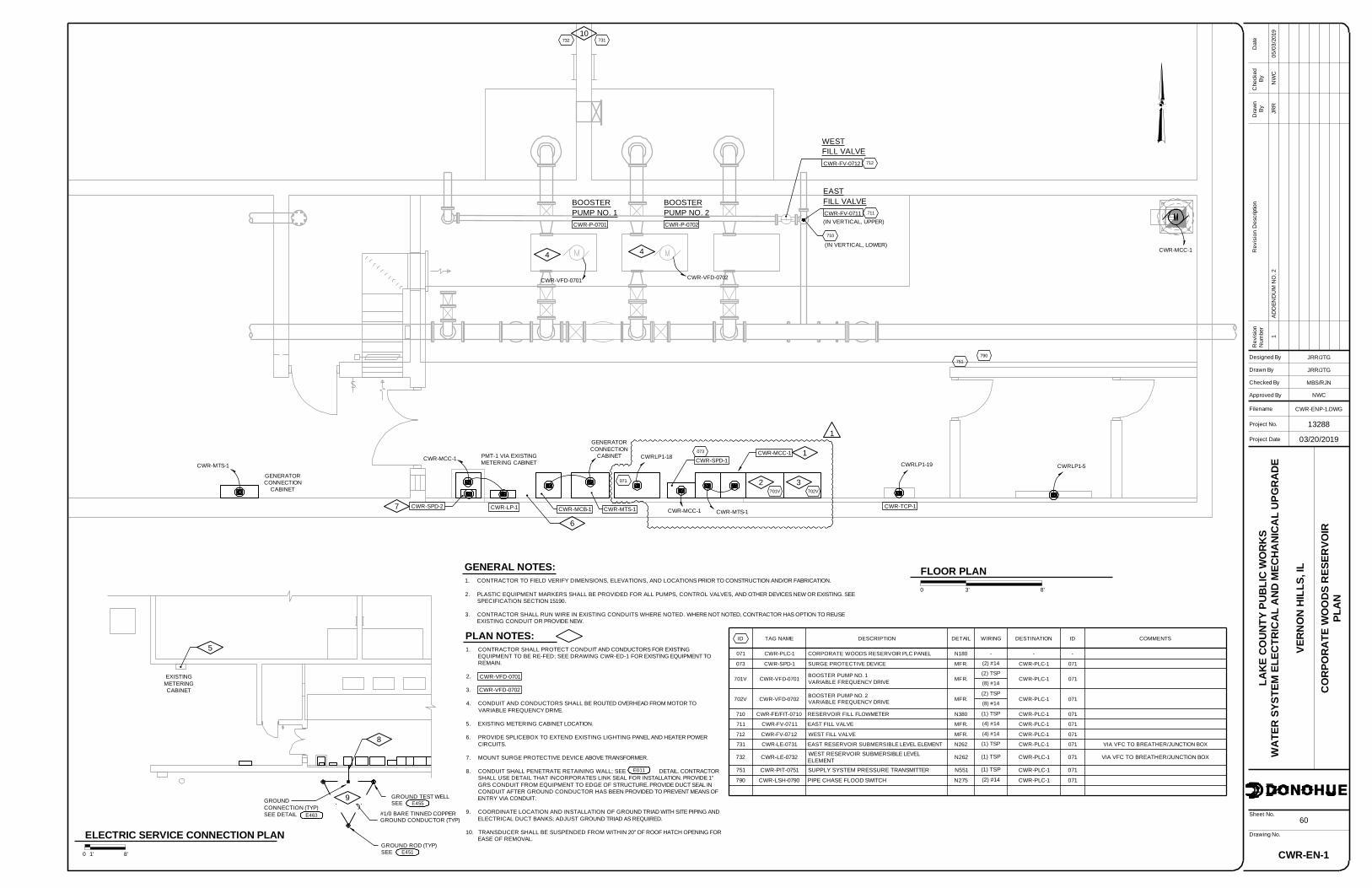
1
PLAN NOTES:1. CONTRACTOR SHALL PROTECT CONDUIT AND CONDUCTORS FOR EXISTING
EQUIPMENT TO BE RE-FED; SEE DRAWING CWR-ED-1 FOR EXISTING EQUIPMENT TOREMAIN.
2.
3.
4. CONDUIT AND CONDUCTORS SHALL BE ROUTED OVERHEAD FROM MOTOR TOVARIABLE FREQUENCY DRIVE.
5. EXISTING METERING CABINET LOCATION.
6. PROVIDE SPLICEBOX TO EXTEND EXISTING LIGHTING PANEL AND HEATER POWERCIRCUITS.
7. MOUNT SURGE PROTECTIVE DEVICE ABOVE TRANSFORMER.
8. CONDUIT SHALL PENETRATE RETAINING WALL; SEE DETAIL. CONTRACTORSHALL USE DETAIL THAT INCORPORATES LINK SEAL FOR INSTALLATION. PROVIDE 1"GRS CONDUIT FROM EQUIPMENT TO EDGE OF STRUCTURE. PROVIDE DUCT SEAL INCONDUIT AFTER GROUND CONDUCTOR HAS BEEN PROVIDED TO PREVENT MEANS OFENTRY VIA CONDUIT.
9. COORDINATE LOCATION AND INSTALLATION OF GROUND TRIAD WITH SITE PIPING ANDELECTRICAL DUCT BANKS; ADJUST GROUND TRIAD AS REQUIRED.
10. TRANSDUCER SHALL BE SUSPENDED FROM WITHIN 20" OF ROOF HATCH OPENING FOREASE OF REMOVAL.
FLOOR PLAN8'3'0
GENERAL NOTES:1. CONTRACTOR TO FIELD VERIFY DIMENSIONS, ELEVATIONS, AND LOCATIONS PRIOR TO CONSTRUCTION AND/OR FABRICATION.
2. PLASTIC EQUIPMENT MARKERS SHALL BE PROVIDED FOR ALL PUMPS, CONTROL VALVES, AND OTHER DEVICES NEW OR EXISTING. SEESPECIFICATION SECTION 15190.
3. CONTRACTOR SHALL RUN WIRE IN EXISTING CONDUITS WHERE NOTED. WHERE NOT NOTED, CONTRACTOR HAS OPTION TO REUSEEXISTING CONDUIT OR PROVIDE NEW.
CWR-MCC-1
CWR-LP-1
CWR-FV-0711
EASTFILL VALVE
(IN VERTICAL, UPPER)CWR-P-0701
BOOSTERPUMP NO. 1
CWR-P-0702
BOOSTERPUMP NO. 2
ID TAG NAME DESCRIPTION DETAIL WIRING DESTINATION ID COMMENTS
071 CWR-PLC-1 CORPORATE WOODS RESERVOIR PLC PANEL N180 - - -
073 CWR-SPD-1 SURGE PROTECTIVE DEVICE MFR. (2) #14 CWR-PLC-1 071
701V CWR-VFD-0701 BOOSTER PUMP NO. 1VARIABLE FREQUENCY DRIVE MFR.
(2) TSPCWR-PLC-1 071
(8) #14
702V CWR-VFD-0702 BOOSTER PUMP NO. 2VARIABLE FREQUENCY DRIVE MFR.
(2) TSPCWR-PLC-1 071
(8) #14
710 CWR-FE/FIT-0710 RESERVOIR FILL FLOWMETER N380 (1) TSP CWR-PLC-1 071
711 CWR-FV-0711 EAST FILL VALVE MFR. (4) #14 CWR-PLC-1 071
712 CWR-FV-0712 WEST FILL VALVE MFR. (4) #14 CWR-PLC-1 071
731 CWR-LE-0731 EAST RESERVOIR SUBMERSIBLE LEVEL ELEMENT N262 (1) TSP CWR-PLC-1 071 VIA VFC TO BREATHER/JUNCTION BOX
732 CWR-LE-0732 WEST RESERVOIR SUBMERSIBLE LEVELELEMENT N262 (1) TSP CWR-PLC-1 071 VIA VFC TO BREATHER/JUNCTION BOX
751 CWR-PIT-0751 SUPPLY SYSTEM PRESSURE TRANSMITTER N551 (1) TSP CWR-PLC-1 071
790 CWR-LSH-0790 PIPE CHASE FLOOD SWITCH N275 (2) #14 CWR-PLC-1 071
071
073
701V
731
790
CWR-SPD-2
PMT-1 VIA EXISTINGMETERING CABINET
CWR-MCC-1
702V
CWR-SPD-1
CWR-TCP-1
2
CWR-VFD-0701
CWR-VFD-0702
CWRLP1-18CWRLP1-19 CWRLP1-5
CWR-MCC-1
CWR-VFD-0701 CWR-VFD-0702
4 4
5
711
710
(IN VERTICAL, LOWER)
GENERATORCONNECTION
CABINET
6
CWR-MTS-17
ELECTRIC SERVICE CONNECTION PLAN1' 8'0
751
732
CWR-FV-0712
WESTFILL VALVE
712
3
EXISTINGMETERINGCABINET
GROUND ROD (TYP)E451
E463GROUND CONDUCTOR (TYP)#1/0 BARE TINNED COPPER
SEE
GROUNDCONNECTION (TYP)SEE DETAIL
GROUND TEST WELLE455SEE
CWR-MCB-1
CWR-MTS-1
GENERATORCONNECTION
CABINET
E011
8
9
CWR-MTS-1
10
CWR-MCC-1
1

HVA
CSC
HEDU
LES
AND
STAN
DAR
DDE
TAIL
S
999-PH-1
66
CAH
CAH
JLW
01AD
DEN
DU
MN
O.2
CAH
NW
C05
/03/
19
Drawing No.
Designed By
Checked By
Filename
Approved By
Project No.
Drawn By
Rev
isio
nN
umbe
rR
evis
ion
Des
crip
tion
Dra
wn
ByD
ate
Che
cked
By
Sheet No.
Project Date
LAKE
COUN
TYPU
BLIC
WO
RKS
WAT
ERSY
STEM
ELEC
TRIC
ALA
NDM
ECHA
NICA
LUP
GRA
DE
VERN
ON
HILL
S,IL
13288
03/20/2019
NWC
999HD.DWG
ELECTRIC CONVECTOR SCHEDULEMANUFACTURERTAG NO.
CWR-ECV-1 CADET
KWMODEL NUMBER
4F1000-8 1 8.3120/1
SECTION 15765
REMARKS
1,2
VOLT/Ø(FT)
MOUNT.HEIGHTAMP
0
1. = WALL MOUNTED UNIT.2. = POWDER COAT PAINT SYSTEM FINISH
CEILING FAN SCHEDULEMANUFACTURERTAG NO.
GLR-CF-1 EMERSON
WMODEL NUMBER
HF948W 72 120/1
SECTION 15803
REMARKS
-
VOLT/Ø(FT)
MOUNT.HEIGHTAMP
SECTION 15752
TYPEFILTER
1" TA
LAT(°F)(DB/WB)
56.4/52
(DB/WB)EAT(°F)
122 80/673.3
FLA(AMP) TGC
(MBH)HP
0 2
(IN WC)ESP
0.5
(CFM)MIN OA VOLTAGE
460/3
COOLING DATA
TGC = TOTAL GROSS CAPACITYSHC = SENSIBLE HEAT CAPACITY.1. = SUPPLY FAN MOTOR SPEED MODULATION CONTROL PACKAGE.2. = SUB BASE AND VIBRATION ISOLATORS.
REMARKS
1,2
FLOOR MOUNTED AIR HANDLING UNIT SCHEDULEMODEL
ODYSSEY-TWE1204*B*
MANUF.
TRANE
TAG NO.
HCR-ACU-1
CFM
3500
* = CAPACITY AT SCHEDULED SST AND AMBIENT TEMPERATURE.1. = MATCHED WITH COOLING COIL FROM HCR-ACU-1.2. = DUAL COMPRESSORS.3. = ETL LABELED.4. = EPOXY COATED CONDENSER COILS.5. = MINIMUM 2 STAGE COOLING.
SECTION 15752AIR COOLED CONDENSER SCHEDULE
HCR-ACCU-1
TAG NO.
ODYSSEY-TWA1204*D*TRANE
MODELMANUF AMB. TEMP
410
REFRIGERANT
120
(MBH)
10
(TONS)
TOTALCAPACITY*CAPACITY
NOMINAL(°F)CIRCUIT
2 951
STAGES PERCIRCUITS(°F) (AMPS)
460/3---
PHASE
1,2,3,4,520.3
SST VOLT/ REMARKSMCA
92.2
NET SHC(MBH)
TSP INCLUDES ACCESSORIES SUCH AS FILTERS AND GRAVITY BACKDRAFT DAMPERS THAT ARE FURNISHED WITH THE FAN.1. = ALUMINUM CONSTRUCTION.2. = STAINLESS STEEL FAN SHAFT AND FASTENERS.3. = NEMA 3R INTEGRAL DISCONNECT.4. = ALUMINUM BIRDSCREEN.5. = GRAVITY OPERATED DAMPER.6. = 2-INCH ALUMINUM FILTERS7. = 12-INCH PREFABRICATED GALVANIZED ROOF CURB.8. = HOODED WALL CAP.9. = WALL SWITCH.
700
RPMFANMODEL NUMBERTAG NO.
HCR-EF-1
MANUFACTURER
GREENHECK SP-B90
FAN SCHEDULE
EXHAUST
SERVICETYPE
FANBATHROOM 75
CFM
AIR FLOW DATA
(IN. W.C.)0.20
ESP
-
BHP
20W
HP/WATTSDRIVE
DIRECT
SONES
2
ELECTRICAL DATA
120
VOLTS
1
PHASE
-
RPM
SECTION 15830
REMARKS
8,9
1. = ROOF CURB ADAPTER. CONTRACTOR SHALL VERIFY SIZE.2. = ALUMINUM BIRD SCREEN.3. = ALUMINUM HOOD.
MAX. THROAT
GRAVITY VENTILATOR SCHEDULEMANUFACTURERTAG NO.
HCR-RH-1 GREENHECK
SERVICEMODEL NUMBER
GRSR-30 RELIEF 5.03
(FT^2)AREA
THROATCFM
2500
VELOCITY
500
(FPM)
SECTION 15830MAX.
0.05
APD(IN. W.C.)
REMARKS
1,2,3
1550HCR-SF-1 GREENHECK LSF-12 SUPPLYPENTHOUSEROOF 2500 0.40 0.48 3/4BELT 14 460 3 1725 1,3,6,7
SECTION 15752
LAT(°F)(DB/WB)
-
(DB/WB)EAT(°F)
48 80/671.9
FLA(AMP) TOT CAP
(MBH)HP
-
VOLTS
208
COOLING DATA
1. = WALL MOUNTED WIRED REMOTE CONTROLLER.
REMARKS
CEILING SUSPENDED DUCT FREE SPLIT SYSTEM SCHEDULEMODEL
40MKCB54F-3
MANUF.
CARRIER
TAG NO.
GLR-ACU-1
CFM
1470
PHASE
1
* = CAPACITY AT SCHEDULED SST AND AMBIENT TEMPERATURE1. = MATCHED WITH COOLING COIL FROM CEILING SUSPENDED DUCT FREE SPLIT SYSTEM SCHEDULE.2. = WALL MOUNTING KIT.3. = WINTER START CONTROL.4. = LOW AMBIENT KIT.5. = CRANK CASE HEATER.6. = WIND BAFFLES.7. = LOW AMBIENT CONTROLS (-20F).
SECTION 15752SPLIT SYSTEM AIR COOLED CONDENSER SCHEDULE
GLR-ACCU-1
TAG NO.
25AHA448CARRIER
MODELMANUF AMB. TEMP
R-410A
REFRIGERANT
48
(MBH)
4
(TONS)
TOTALCAP*CAP
NOMINAL(°F)
1 95
STAGES(°F) (AMPS)
480/3---
PHASE
8.6
SST VOLT/ REMARKSMCA(MBH)
REQSEN CAP
35
1
1,2,3,4,5,6,7
35
SEN CAP(MBH)
MOTOR OPERATED DAMPER SCHEDULETYPE
INSULATED
TAG NO.
HCR-ICD-1
BLADESFUNCTION
OPEN/CLOSE PARALLEL 22
(IN.)WIDTH
2500
CFM
18
(IN.)HEIGHT
SECTION 15905
2
FAIL POS.
CLOSE CC 1,2
REMARKSNEMA
ELECTRICAL
SUPPLY
SERVICE MOUNTINGENCLOSURE
DUCT
CC = CONTRACTORS CHOICE.1. = COORDINATE SIZE WITH FAN DUCT SIZE.2. = FULL OPEN LIMIT SWITCH.
1022CWR-EF-1 GREENHECK GB-161 EXHAUSTCENTRIROOF 2300 0.40 0.46 3/4BELT 13 460 3 1725 1,2,3,4,5
(IN. W.C.)0.20
TSP
0.40
0.50
GLR-CF-2 EMERSON HF948W 72 120/1 -
INSULATEDCWR-ICD-1 OPEN/CLOSE PARALLEL 282600 14 2CLOSE CC 1,2SUPPLY DUCT
ANOD = ANODIZED FINISH.DD = 3/4" BLADE DOUBLE DEFLECTION.EGG = 1"X1"X1" EGGCRATE.
MODEL
RASM
AIR INLET AND OUTLET SCHEDULE
CARNESSG-1
MANUFACTURERTAG NO. APD
SUPPLY 30
NC(IN. W.C.)
0.10
SERVICE MAX.MAX.
ANODDD ALUM
FINISHPATTERN MATERIAL
SECTION 15875
REMARKS
FINISHED FLOORSIZE TO 6" ABOVEPIPE DISCHARGE FULL
PRESSURE RELIEF VALVETEMPERATURE ANDASME APPROVED
THERMOMETER
UNION, TYP
HOT WATER, SEE
WATER HEATER
PLANS FOR SIZE
COLD WATER, SEEPLANS FOR SIZE
WATER HEATER DETAIL P452NTS
V376, VALVE SIZEEQUAL TO PIPE SIZE
RAEACARNESSG-2 SUPPLY 300.05 ANODEGG ALUM
1. = ALUMINUM BIRDSCREEN.2. = EXTENDED SILL.3. = 70% KYNAR FINISH.
WALL LOUVER SCHEDULEMANUFACTURER
GREENHECK
TAG NO.
CWR-OAL-1
SERVICEMODEL NUMBER
ESD-403 INTAKE 32
(IN.)WIDTH
2300
CFM
40
(IN.)HEIGHT
SECTION 15875
0.05
(IN. W.C.)DEPTH(IN.)
4
MAX.APD
550
AREA VEL.MAX. FREE
(FPM)
1,2,3
REMARKS
ROOF MEMBRANE
INSULATION
CONCRETE ROOF
VENT THRU ROOF DETAIL P210NTS
DECK PANEL
MIN 10" FROM VENT PIPEFLASHING MEMEBRANE. EXTEND
LAP SEALANT
4" MIN10" MIN
NOTE: PROVIDE WHEREVER NOTED AS VTR ON PLANS AND ISOMETRICS
SEALANT AT PENETRATIONTO MEMBRAINE JUNCTURE
VENT PIPE. EXTENDMIN 12" ABOVE ROOFSEE PLANS FOR SIZE
1
1

HVA
CSC
HEDU
LES
AND
STAN
DAR
DDE
TAIL
S
999-H-2
67
CAH
CAH
JLW
Drawing No.
Designed By
Checked By
Filename
Approved By
Project No.
Drawn By
Rev
isio
nN
umbe
rR
evis
ion
Des
crip
tion
Dra
wn
ByD
ate
Che
cked
By
Sheet No.
Project Date
LAKE
COUN
TYPU
BLIC
WO
RKS
WAT
ERSY
STEM
ELEC
TRIC
ALA
NDM
ECHA
NICA
LUP
GRA
DE
VERN
ON
HILL
S,IL
13288
03/20/2019
NWC
999HD.DWG
INSULATED CURB COVER H980NTS
EXIST CONCRETEHVAC CURB
14" AL PLATE
SS FASTENER
PROVIDE NEOPRENEGASKET AT CURB/CAPINTERFACE
14" AL CLOSURE PL
SS FASTNER, 6" OC. FULLLENGTH OF EACH CHANNEL
18" AL BOTTOM PL
2" RIGID INSULATION
NOTES:
1. FIELD VERIFY ALL EXISTING OPENINGS AND CURBS PRIOR TOFABRICATION.
2. SHOP WELD CLOSURE PLATES AND CHANNELS TO TOP COVER.3. RIGID INSULATION SHALL HAVE A MINIMUM R-VALUE OF 5/INCH.
INTAKE/RELIEF HOOD ONCONCRETE CURB DETAIL H231NTS
SEE PLANS FOR DUCT SIZE
CONCRETE DECKROOF INSULATION
TREATED WOOD 2x4, ANCHORTO CONCRETE CURB WITHSTAINLESS STEEL ANCHORS
ALUMINUM COUNTERFLASHING
BIRDSCREEN
EXHAUST HOOD
S325NEW OR EXISTING CONCRETE CURB, SEEPLANS. IF NEW, SEE
ANCHOR TO NAILER IN ACCORDANCEWITH MANUFACTURERSINSTALLATION INSTRUCTIONS
GRAVITY BACKDRAFT DAMPER
SUPPLY FAN DETAIL H221NTS
CONCRETE DECK
SEE PLANS FOR DUCT SIZE
ROOF INSULATION
6"
LOUVERED INTAKE SUPPLY FAN
ROOF CURB FURNISHEDWITH FAN
INSULATED CONTROL DAMPERDAMPER AS SHOWN ON PLANS
FLASH IN ACCORDANCEWITH ROOF CURBMANUFACTURER'SRECOMMENDATIONS
ANCHOR HOOD TO CURB INACCORDANCE WITH MANUFACTURER'SINSTALLATION INSTRUCTIONS
PIPE WALLPENETRATION DETAIL H024NTS
CORE DRILL ASREQUIRED FOR PIPE
INSULATION
PASSING PIPE
SEALANT
INTERIORCONCRETE WALL
EXHAUST FAN ONA CONCRETE CURB DETAIL H222NTS
10"
6"
45°
S325
EXPANDED METAL(MIN. 50% FREE AREA)
2" DEEP DRIP PAN, SOLDERALL SEAMS WATERTIGHT
NOTE: INSTALL SUCH THAT BOTTOM OF DUCT IS MINIMUM 4" ABOVE HIGHEST POINT ON BRIDGE CRANE
NEW CONCRETE CURB, SEE
ALUMINUM COUNTERFLASHING
TREATED WOOD 2x4, ANCHORTO CONCRETE CURB WITHSTAINLESS STEEL ANCHORS
EXHAUST FAN
ANCHOR TO NAILER IN ACCORDANCEWITH MANUFACTURERS INSTALLATIONINSTRUCTIONS
CONCRETE DECK
SEE PLANS FOR DUCT SIZE
ANGLE IRON FRAME
GRAVITY BACKDRAFT DAMPER
IF PLANS CALL FOR DUCT TO ENDNEAR CEILING, PROVIDE WATERTIGHT DRIP PAN BELOW DUCT
OVERLAP CONCRETECURB AT LEAST 2-INCHWHERE POSSIBLE
NOTE: ALL FASTENERS SHALL BE OF STAINLESS STEEL CONSTRUCTION
TYPICAL LOUVER DETAIL H020NTS
1/8" ALUMINUM ANGLE ALONG BOTTOM OFOPENING OF HIEGHT REQUIRED TO ALIGN 1"ABOVE LOUVER DRAIN JAMB, PROVIDEALUMINUM SHEET COVER BETWEEN ANGLE ANDCLIP ANGLE TO ALLOW WATER TO DRAIN FROMDUCT TO LOUVER
SINGLE FLANGED DAMPER WHEREINDICATED ON PLANS ORSCHEDULES. ACTUATOR FOR MOTOROPERATED DAMPERS SHALL BELOCATED OUTSIDE OF THEAIRSTREAM
DUCT, FOR LOCATIONS WHEREDAMPER INDICATED, FASTEN DUCTTO PERIMETER OF DAMPER FRAME.FOR LOCATIONS WITHOUTDAMPERS, FASTEN DUCT TO WALLWITH DUCT FLANGE ALONG TOPAND SIDES AND TO ANGLE ATBOTTOM
FOR UNDUCTED APPLICATIONS WITHDAMPERS, PROVIDE DUCT EXTENSIONPAST DAMPER AND MIN 50% FREE AREAALUMINUM EXPANDED METAL. MOUNTDAMPER OPERATOR OUTSIDE OFENCLOSURE.
CLIP ANGLES, FULL LOUVER PERIMETER
MOUNTING HEIGHT AS INDICATEDON PLANS OR SCHEDULE
EXTERNAL INSECT SCREEN
LOUVER, SIZE AS INDICATED
WEATHER RESISTANT CAULK,
ON PLANS
EXTENDED SILL
ALUMINUM BIRDSCREEN
IF SCHEDULED
FULL PERIMETER
PROVIDE WALL OPENING AS REQUIRED
FASTENER, TYPINSULATE ANY DUCTWORKBETWEEN WALL AND DAMPER 1
01AD
DEN
DU
MN
O.2
CAH
NW
C05
/03/
19