advance electromagnet security system with gsm interface · international journal of scientific...
TRANSCRIPT
International Journal of Scientific & Engineering Research, Volume 7, Issue 11, November-2016 1897 ISSN 2229-5518
IJSER © 2016 http://www.ijser.org
“ADVANCE ELECTROMAGNET SECURITY SYSTEM
WITH GSM INTERFACE”
A.V.Pandit [email protected] (8007812353)
N.C.Oza
[email protected] (7774898128)
S.D.Nimbhorkar [email protected] (7385881680)
S S Padheye
[email protected] (7507778038)
ABSTRACT The Electromagnet Door Lock is a lock that is simple to install and allows the
user to easily lock and unlock doors. It will contain a Electromagnet driver and a
magnetic door lock for simple use. All the user will need is an Electromagnet tag to
be able to unlock and lock the door. A LCD will be used to let the user know when
the door is in fact locked. The components included in the module are small and
compact. Additionally, the door lock is simple and easy to install. It does not require
the consumer to disassemble the door or door frame as the door lock are merely
attachments. This is also leaves the consumer with the option of using their original
lock and key if they so choose. All in all, this Electromagnet door lock should be a
simple and cost effective upgrade to the average consumer’s security and
convenience.
IJSER
International Journal of Scientific & Engineering Research, Volume 7, Issue 11, November-2016 1898 ISSN 2229-5518
IJSER © 2016 http://www.ijser.org
CHAPTER 1
INTRODUCTION:
1.1 Problem Overview: The increasing rate of crime, attacks by thieves, intruders and vandals,despite all
forms of security gadgets and locks still need the attention of researchers to find a
permanent solution to the well being of lives and properties of individuals. To this
end, we design a cheap and effective security system for buildings, cars, safes, doors
and gates, so as to prevent unauthorized person from having access to ones properties
through the use of codes, we therefore experiment the application of electronic
devices as locks. However, a modular approach was employed in the design in which
the combination lock was divided into units and each unit designed separately before
being coupled
1.2 Aim of Project:
Due to the advancement of science and technology throughout the world,
there is a consequent increase in the rate and sophistication of crime As a result, it is
necessary to ensure security of oneself and one’s valuable belongings. Even with the
use of mechanical locks, the crime rate still has increased due to the fact that these
locks are easily broken. Consequently, there is a need for other types of locks
especially electromagnet ones.
1.3Objective of Project:
Therefore, the main objectiveof the project design are:
To design a economical and effective security system for buildings, offices, safes,
doors and gates etc.,
To experiment the application of electromagnetic devices as locks, and
To prevent unauthorized person from having access to ones properties through
the use of code
Sophisticated to easy locking and unlocking
IJSER

International Journal of Scientific & Engineering Research, Volume 7, Issue 11, November-2016 1899 ISSN 2229-5518
IJSER © 2016 http://www.ijser.org
1.4 Sub Objectives of the Project:- 1. To Study Working of Electromagnetic Materials:
In this project we will study the actual working of electromagnetic materials. We will
also study that how much holding force we have to apply on electromagnetic
stamping to get required appropriate output.
2. Selection of Appropriate Components Required:
In this part of the system we will select the components required of specific and
appropriate ratings such as rectifier, filter, regulator, inverter, etc.
3. Design of Block And Circuit Diagram:
The another objective of our project is to study and design block diagram and circuit
for proposed system.
4. Overall Reduced Cost:
To reduce the cost for safety purpose besides increasing the efficiency of proposed
the system.
1.5 Outlines of the Dissertation: Chapter 2- Literature Review:
Chapter 3- Objective Completed: Out of the above mention objectives, till we are
able to complete the some objectives only.
Chapter 4- Significance of Topic: Importance.
Chapter 5– Principle of Operation: The working principle of the Electromagnetic
door lock system is mentioned.
Chapter 6- Project Development Stages: The information about how to develop the
project.wise description of project development.
Chapter 7- Hardware Design: The information about the hardware completed by us.
Chapter 8- Controller Design: The controller used by us and its specifications.
IJSER

International Journal of Scientific & Engineering Research, Volume 7, Issue 11, November-2016 1900 ISSN 2229-5518
IJSER © 2016 http://www.ijser.org
Chapter 9- Block Diagram Description: This chapter gives description of block
diagram for system.
Chapter 10- Hardware Design Circuitry:
Chapter 11-COMPERATIVE TESTING RESULTS: comparison of previous
results and after hardware results obtained
Chapter 12- Advantages and Disadvantages: Advantages and disadvantages.
Chapter 13- Applications:
Chapter 14- Conclusion:
Chapter 15- Future scope:
Bibliography
IJSER
International Journal of Scientific & Engineering Research, Volume 7, Issue 11, November-2016 1901 ISSN 2229-5518
IJSER © 2016 http://www.ijser.org
CHAPTER 2
LITERATURE REVIEWS
1]Design, Development and Testing of an Electromagnet for magnetic levitation
System ByDahiruSaniShu’aibu and SanusiSaniAdamu Department of Electrical
Engineering Bayero University, Kano Nigeria.
This paper presents details of the design and development of an electromagnet for use
in magnetic door lock control system experiment. The method is purely based on
numerical approach. Cast steel was used as the material, because of its high
permeability and fairly good coercivity. The genesis for the design is based on the
phenomenon of holding
power of a magnet. The design was implemented using a local available component;
the electromagnet was able to holds great amount of force by varying the current
through the winding of the magnet. In the final analysis, the electromagnet was
designed and built with a cost saving value. The electromagnet designed for different
holding forces by taking a current. The force constant of the magnet was determined.
2]We used SECO-LARAM Electromagnet lock manual for design part of
electromagnet from reference books.
The electromagnetic locks is the ideal way to secure a door against unauthorized
entry. When power is applied to the electromagnetic lock, it creates an extremely
strong magnetic field. The electromagnet is strongly attracted to the steel armature
plate which is mounted on the secured door. Once the electromagnet is deactivated,
the secured door will function normally without any residual magnetism.
3]International Journal of Embedded Systems and Applications (IJESA) Vol.2,
No.2, June 2012 DOI : 10.5121/ijesa.2012.2201 1
Development of Low Cost Private Office Access Control System(OACS)
Sadeque Reza Khan Prime University, Department of Electrical and Electronic
Engineering, Dhaka-1216, Bangladesh .
IJSER

International Journal of Scientific & Engineering Research, Volume 7, Issue 11, November-2016 1902 ISSN 2229-5518
IJSER © 2016 http://www.ijser.org
Over the years, access control systems have become more and more sophisticated and
several securitymeasures have been employed to combat the menace of insecurity of
lives and property. This is done bypreventing unauthorized entrance into buildings
through entrance doors using conventional and electroniclocks, discrete access code,
and biometric methods such as the finger prints, thumb prints, the iris andfacial
recognition. We have designed a flexible and low cost modular system based on
integration of
keypad, magnetic lock and a controller. PIC 16F876A which is an 8-bit
Microcontroller, is used here as amain controller. An advanced simulation based
compiler Flowcode V4 is used to develop the software partin this project.
4]The block diagram, block diagramdescription, flowchart ,algorithm referred
from paper reference journal .We referred the electromagnet pdf for
advantages, disadvantages, and application. We use the A.K.SWANEY reference
book for calculation and design part of electromagnet
IJSER
International Journal of Scientific & Engineering Research, Volume 7, Issue 11, November-2016 1903 ISSN 2229-5518
IJSER © 2016 http://www.ijser.org
CHAPTER 3
OBJECTIVES COMPLETED
1.To Design Electromagnet Stamping To Create Holding Force: To create holding force by using electromagnetic material and systems can be
install elsewhere specially in the dense populated areas easily. 2. To Study the working of Electromagnetic Materials:
In this type of material magnetic field is produced by flow of electric current. It
is used electricity to produced magnet force. The main advantages of an
electromagnet over a permanent magnet are that the magnetic field can be rapidly
manipulated over wide range by controlling the amount of electric current.
3. Design of all Circuitry Required for Electromagnetic Lock
System: All the circuits required for electromagnetic lock system are design.
4. To Reduce overall cost of system: The overall cost of system can be reduced as we are using less power input for
the system and also the cost of the components required to make the electromagnetic
lock is low and so of the system.
IJSER

International Journal of Scientific & Engineering Research, Volume 7, Issue 11, November-2016 1904 ISSN 2229-5518
IJSER © 2016 http://www.ijser.org
CHAPTER 4
SIGNIFICANCE OF TOPIC 4.1Significance of Topic: 1.The goal of the project is to develop a unique system through mobile
technology,which can control various units of the houses, industries, and also
provides a security system.
2. The various appliances can be utilized by managing them remotely by using GSM
technology, which enables the user to remotely controlthe operations of the
appliances.
3. Just by pressing keypad of remote telephonethe user can perform ON/OFF
operations on the appliances.
4. Unlock the door by using pre-decided password.
5. Increase the security level to prevent an unauthorized unlockingof the door.
6. To prevent the opening of the door by unauthorized persons.
7. Flexibility to the user to change or reset the password
8. More secure yet cost-efficient way of door locking-unlocking system.
9. Contains a matrix key pad, door system and a GSM modem for the security dial up
interfaced to the micro controller.
10.The keypad interfaced to the controller is used as the password entry.
11. As soon as the user enters the correct password, the door lock opens.
4.2Constraints or Difficulties Faced: 1.Design of electromagnet winding:
IJSER

International Journal of Scientific & Engineering Research, Volume 7, Issue 11, November-2016 1905 ISSN 2229-5518
IJSER © 2016 http://www.ijser.org
While Designing the Electromagnet of required high holding force, SWG of
the conductor should be large. As SWG of conductor is greater thendiameter of
conductor get reduced, so it will going difficult to making winding of electromagnet.
CHAPTER 5
IJSER
International Journal of Scientific & Engineering Research, Volume 7, Issue 11, November-2016 1906 ISSN 2229-5518
IJSER © 2016 http://www.ijser.org
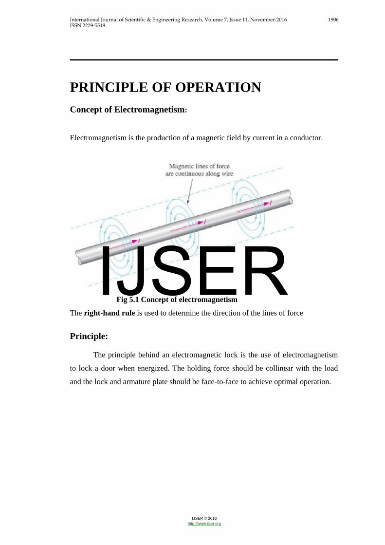
PRINCIPLE OF OPERATION Concept of Electromagnetism:
Electromagnetism is the production of a magnetic field by current in a conductor.
Fig 5.1 Concept of electromagnetism
The right-hand rule is used to determine the direction of the lines of force
Principle:
The principle behind an electromagnetic lock is the use of electromagnetism
to lock a door when energized. The holding force should be collinear with the load
and the lock and armature plate should be face-to-face to achieve optimal operation.
IJSER

International Journal of Scientific & Engineering Research, Volume 7, Issue 11, November-2016 1907 ISSN 2229-5518
IJSER © 2016 http://www.ijser.org
Fig 5.2 Working of electromagnetic door lock.
Operation:
An electromagnetic lock, magnetic lock, or maglock is a locking device that consists
of an electromagnet and an armature plate. There are two main types of electric
locking devices. Locking devices can be either "fail safe" or "fail secure". A fail-
secure locking device remains locked when power is lost. Fail-safe locking devices
are unlocked when de-energized. Direct pull electromagnetic locks are inherently fail-
safe. Typically the electromagnet portion of the lock is attached to the door frame and
a mating armature
plate is attached to the door. The two components are in contact when the door is
closed. When the electromagnet is energized, a current passing through the
IJSER

International Journal of Scientific & Engineering Research, Volume 7, Issue 11, November-2016 1908 ISSN 2229-5518
IJSER © 2016 http://www.ijser.org
electromagnet creates a magnetic flux that causes the armature plate to attract to the
electromagnet, creating a locking action. Because the mating area of the
electromagnet and armature is relatively large, the force created by the magnetic flux
is strong enough to keep the door locked even under stress.Typical single door
electromagnetic locks are offered in 200kg. dynamic holding force capacities. A "fail
safe" magnetic lock requires power to remain locked and typically is not suitable for
high security applications because it is possible to disable the lock by disrupting the
power supply. Despite this, by adding a magnetic bond sensor to the lock and by
using a power supply that includes a battery backup capability, some specialized
higher security applications can be implemented. Electromagnetic locks are well
suited for use on emergency exit doors that have fire safety applications because they
have no moving parts and are therefore less likely to fail than other types of electric
locks, such as electric strikes.
The strength of today's magnetic locks compares well with that of
conventional door locks and they cost less than conventional light bulbs to operate.
There are additional pieces of release hardware installed in a typical electromagnetic
locking system. Since electromagnetic locks do not interact with levers or door knobs
on a door, typically a separate release button that cuts the lock power supply is
mounted near the door. This button usually has a timer that, once the button is
pressed, keeps the lock unlocked for either 15 or 30 seconds in accordance with
NFPA fire codes. Additionally a second release is required by fire code. Either a
motion sensor or crash bar with internal switch is used to unlock to door on the egress
side of the door automatically.
IJSER

International Journal of Scientific & Engineering Research, Volume 7, Issue 11, November-2016 1909 ISSN 2229-5518
IJSER © 2016 http://www.ijser.org
CHAPTER 6
PROJECT DEVLOPMENT STAGES 1. Calculation for design of electromagnet: Calculate the pole area where the winding to be wounded.
From the assumption of force we calculate the no. of turns, current and MMF
2. Developmentof Electromagnet: We are going to use E-shape CRNO magnetic material.
Then make stamping of E-shape strips.
After the making of stamping we wound the winding on middle part of
stamping.
3. Development of Electromagnet Driver Circuit:
By using circuit diagram driver circuit is designed.
After receiving signal from controller Electromagnet driver circuitwork .
And gives the 12v supply to the electromagnet
4. Development of Power Supply Circuit: By using circuit diagram power supply circuit is designed.
It provides 5v dc to controller.
5. Connection of LCD, Keypad and Battery:
Connect the keypad for enter the password. Connect LCD to show the door status. And battery act as bypass for power supply
6. Controller Design and Its Programming:
ATMEGA 328 controller selected.
Programming for door opening
7. Actual Implementation and testing of partial hardware
Implementation of each circuit n testing of whole system ,work
successfully.
IJSER
International Journal of Scientific & Engineering Research, Volume 7, Issue 11, November-2016 1910 ISSN 2229-5518
IJSER © 2016 http://www.ijser.org
CHAPTER 7
HARDWARE DESIGN 7.1 Component Selection: 1. Power supply
Transformer 230/15V AC.
Diode Bridge IN4007
Electrolyte Capacitor
Voltage Regulator
Resistor and LED
2. Driver Circuit:
Transistor BC547
Resistor and LED
3. Arduino Microcontroller
Advanced RISC Architecture
High Performance, Low Power Atmel®AVR® 8-Bit Microcontroller
Family
8 bit microcontroller.
28 pin IC, 23 I/p pins.
14 digital I/O pin
8 analog I/P pin
Inbuilt PWM
Inbuilt ADC
4. Keypad
Ultra-thin design
Adhesive backing
Excellent price/performance ratio
Easy interface to any microcontroller
Example programs provided for the BASIC
5.Electromagnet Material
IJSER

International Journal of Scientific & Engineering Research, Volume 7, Issue 11, November-2016 1911 ISSN 2229-5518
IJSER © 2016 http://www.ijser.org
Electromagnet stamping-E shape CRGO material
Winding-insulated copper type A supper enamel
Insulating material-Bobbin .
CHAPTER 8
IJSER
International Journal of Scientific & Engineering Research, Volume 7, Issue 11, November-2016 1912 ISSN 2229-5518
IJSER © 2016 http://www.ijser.org
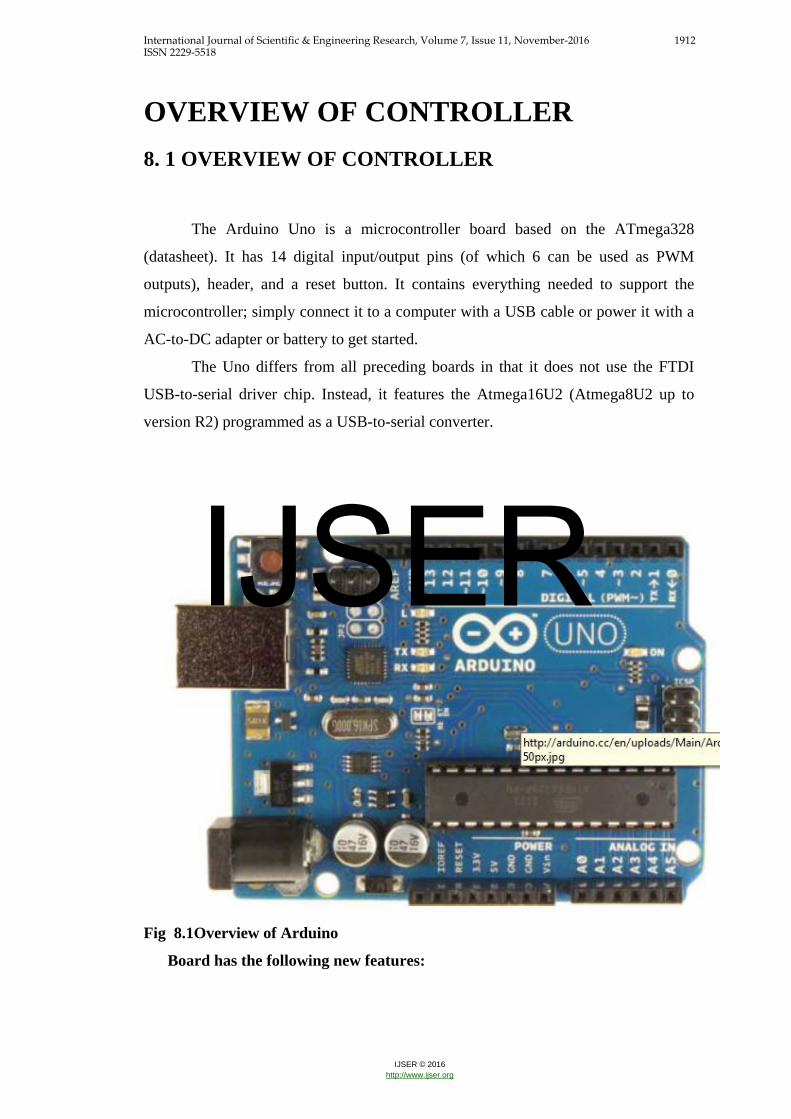
OVERVIEW OF CONTROLLER
8. 1 OVERVIEW OF CONTROLLER
The Arduino Uno is a microcontroller board based on the ATmega328
(datasheet). It has 14 digital input/output pins (of which 6 can be used as PWM
outputs), header, and a reset button. It contains everything needed to support the
microcontroller; simply connect it to a computer with a USB cable or power it with a
AC-to-DC adapter or battery to get started.
The Uno differs from all preceding boards in that it does not use the FTDI
USB-to-serial driver chip. Instead, it features the Atmega16U2 (Atmega8U2 up to
version R2) programmed as a USB-to-serial converter.
Fig 8.1Overview of Arduino
Board has the following new features:
IJSER
International Journal of Scientific & Engineering Research, Volume 7, Issue 11, November-2016 1913 ISSN 2229-5518
IJSER © 2016 http://www.ijser.org
1.0 pinout: added SDA and SCL pins that are near to the AREF pin and two other
new pins placed near to the RESET pin, the IOREF that allow the shields to adapt
to the voltage provided from the board. In future, shields will be compatible both
with the board that use the AVR, which operate with 5V and with the Arduino
Due that operate with 3.3V.
The second one is a not connected pin, that is reserved for future purposes.
Stronger RESET circuit.
Atmega 16U2 replace the 8U2.
"Uno" means one in Italian and is named to mark the upcoming release of
Arduino 1.0. The Uno and version 1.0 will be the reference versions of Arduino,
moving forward. The Uno is the latest in a series of USB Arduino boards
Summary
Microcontroller ATmega328
Operating Voltage 5V
Input Voltage (recommended) 7-12V
Input Voltage (limits) 6-20V
Digital I/O Pins 14 (of which 6 provide PWM output)
Analog Input Pins 6
DC Current per I/O Pin 40 mA
DC Current for 3.3V Pin 50 mA Flash Memory 32 KB (ATmega328) of which 0.5 KB used by bootloader SRAM 2 KB (ATmega328) EEPROM 1 KB (ATmega328) Clock Speed 16 MHz
CHAPTER 9
IJSER
International Journal of Scientific & Engineering Research, Volume 7, Issue 11, November-2016 1914 ISSN 2229-5518
IJSER © 2016 http://www.ijser.org
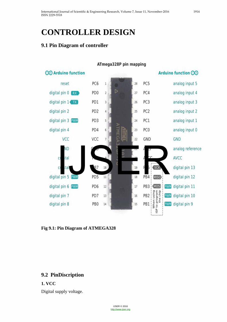
CONTROLLER DESIGN 9.1 Pin Diagram of controller
Fig 9.1: Pin Diagram of ATMEGA328
9.2 PinDiscription 1. VCC
Digital supply voltage.
IJSER
International Journal of Scientific & Engineering Research, Volume 7, Issue 11, November-2016 1915 ISSN 2229-5518
IJSER © 2016 http://www.ijser.org
2. GND
Ground.
3. Port B (PB7:0) XTAL1/XTAL2/TOSC1/TOSC2
Port B is an 8-bit bi-directional I/O port with internal pull-up resistors (selected for
each bit). The Port B output buffers have symmetrical drive characteristics with both
high sink and source capability. As inputs, Port B pins that are externally pulled low
will source current if the pull-up resistors are activated. The Port B pins are
tristed.when a reset condition becomes active, even if the clock is not running.
Depending on the clock selection fuse settings, PB6 can be used as input to the
inverting Oscillator amplifier and input to the internal clock operating circuit.
Depending on the clock selection fuse settings, PB7 can be used as output from the
inverting Oscillator amplifier.
If the Internal Calibrated RC Oscillator is used as chip clock source, PB7...6 is used
as TOSC2...1 input for the Asynchronous Timer/Counter2 if the AS2 bit in ASSR is
set.
4. Port C (PC5:0)
Port C is a 7-bit bi-directional I/O port with internal pull-up resistors (selected for
each bit). The PC5...0 outputbuffers have symmetrical drive characteristics with both
high sink and source capability. As inputs, Port C pins that are externally pulled low
will source current if the pull-up resistors are activated. The Port C pins are trites
when a reset condition becomes active, even if the clock is not running.
5. PC6/RESET
If the RSTDISBL Fuse is programmed, PC6 is used as an I/O pin. Note that the
electrical characteristics of PC6differ from those of the other pins of Port C.
If the RSTDISBL Fuse is programmed, PC6 is used as a Reset input. A low level on
this pin for longer than the minimum pulse length will generate a Reset, even if the
clock is not running.
6 Port D (PD7:0)
Port D is an 8-bit bi-directional I/O port with internal pull-up resistors (selected for
each bit). The Port D output buffers have symmetrical drive characteristics with both
high sink and source capability. As inputs, Port D pins that are externally pulled low
will source current if the pull-up resistors are activated. The Port D pins are tractates
when a reset condition becomes active, even if the clock is not running.
7. AVCC
IJSER
International Journal of Scientific & Engineering Research, Volume 7, Issue 11, November-2016 1916 ISSN 2229-5518
IJSER © 2016 http://www.ijser.org
AVCC is the supply voltage pin for the A/D Converter, PC3:0, and ADC7:6. It
should be externally connected to VCC, even if the ADC is not used. If the ADC is
used, it should be connected to VCC through a low-pass filter.
Note that PC6...4 use digital supply voltage, VC 8. AREF
AREF is the analog reference pin for the A/D Converter.
9. ADC7:6 (TQFP and QFN/MLF Package Only)
In the TQFP and QFN/MLF package, ADC7:6 serve as analog inputs to the A/D
converter. These pins are Powered from the analog supply and serve as 10-bit ADC
channels.
CHAPTER 10
BLOCK DIAGRAM DESCRIPTION
IJSER

International Journal of Scientific & Engineering Research, Volume 7, Issue 11, November-2016 1917 ISSN 2229-5518
IJSER © 2016 http://www.ijser.org
10.1 Design of Proposed System:
Fig10.1 Block Diagram of Electromagnetic lock system
1. Power Supply:
It consist of single phase 230 volt power supply .For operation of microcontroller and
electromagnet we require 5Vand12V DC respectively.
2.Electromagnet driver: Electromagnet driver block control the on-off operation of electromagnet.
3. Electromagnetic Lock:
The Magnetic lock uses an electrical current to produce aelectromagnetic
force. When a current is passed through the coil, the magnet lock becomes
magnetized. The door will be securely bonded when the electromagnet is energized
holding against the armature plate. The magnetic lock is
Simple locking device that consists of a magnetic lock and armature plate with no
moving parts and it purely works due to the magnetic field
IJSER
International Journal of Scientific & Engineering Research, Volume 7, Issue 11, November-2016 1918 ISSN 2229-5518
IJSER © 2016 http://www.ijser.org
5 .Microcontroller:
The control module is built with the microcontroller IC. The central controller
is Microchip ATMEGA328 which is an 8-bit Microcontroller with up to eight
channels built-in A/D converter and 23 I/O pins . This microcontroller IC manages
overall DACS operations. It collects password from keypad, processes password and
decides whether it is valid or not. One of the advantages of microcontrollers is low
power consumption CMOS technology which makes them flexible for battery
powered applications like this project and wide operating voltage range, for example
ATMEGA328 operates in a voltage range of 2-5.5 volts. 6.LCD:
are going to use 16x2 alphanumeric Liquid Crystal Display (LCD) which
means it can displayalphabets along with numbers on 2 lines each containing 16
characters.
7. Keypad:
User will enter the password using the keypad
8 GSM:
The system is totally designed using GSM and Bluetooth Module. The
Controlling unit has an application program to allow the microcontroller read the
incoming data through the modem and control the electromagnet as per the
requirement
CHAPTER 11
HARDWARE DESIGN CIRCUITARY
IJSER

International Journal of Scientific & Engineering Research, Volume 7, Issue 11, November-2016 1919 ISSN 2229-5518
IJSER © 2016 http://www.ijser.org
11.1 Power supply circuit:
Fig 11.1 power supply circuit
7805&7812 is the 5v,12v respectively fixed two positive voltage regulator
IC.The IC has features such as safe operating area protection ,thermal shut down,
internal current limiting which makes the IC very rugged. Output currents upto 3Acan
be drawn from the IC provided that there is proper heat sink A 15v transformer step
down the main voltage,Bridge rectifier rectifies it &capacitor filters it.And
7805&7812 regulate it to produce steady 5v&12v DC.
11.2 Driver circuit:
IJSER
International Journal of Scientific & Engineering Research, Volume 7, Issue 11, November-2016 1920 ISSN 2229-5518
IJSER © 2016 http://www.ijser.org
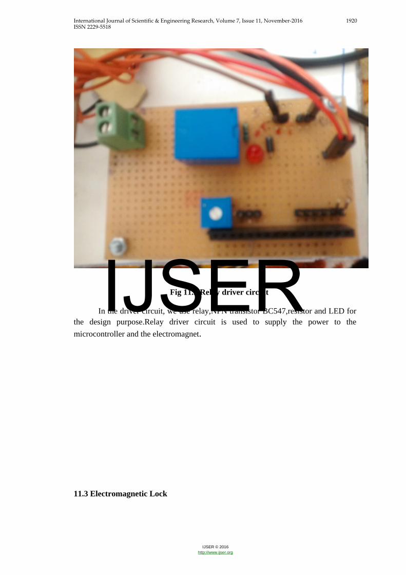
Fig 11.2 Relay driver circuit
In the driver circuit, we use relay,NPN transistor BC547,resistor and LED for the design purpose.Relay driver circuit is used to supply the power to the microcontroller and the electromagnet.
11.3 Electromagnetic Lock
IJSER
International Journal of Scientific & Engineering Research, Volume 7, Issue 11, November-2016 1921 ISSN 2229-5518
IJSER © 2016 http://www.ijser.org
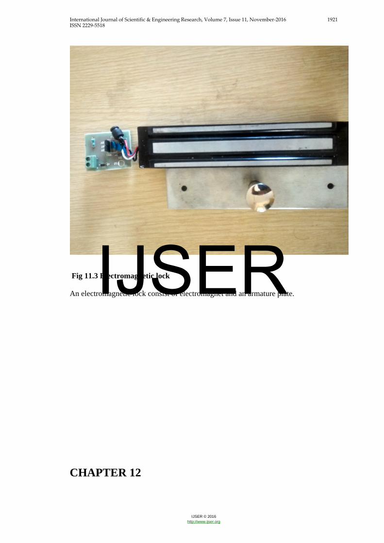
Fig 11.3 Electromagnetic lock An electromagnetic lock consist of electromagnet and an armature plate.
CHAPTER 12
IJSER

International Journal of Scientific & Engineering Research, Volume 7, Issue 11, November-2016 1922 ISSN 2229-5518
IJSER © 2016 http://www.ijser.org
ADVANTAGES &DISADVANTAGE ADVANTAGES:
Easy to install: Electromagnetic locks are generally easier to install than
other locks since there are no interconnecting parts Quick to operate: Electromagnetic locks unlock instantly when the power is
cut, allowing for quick releasing in comparison to other locks sturdy: magnetic locks may also suffers less damage for multiple blows than
do conventional locks if a magnetic lock is forced to open with a crowbar, it
will often do little or no damage to the lock or door. There are no moving part
in electromagnetic lock to break. Fit for wooden door, metal door, glass door, fire proof door etc Good quality and durable to use
DISADVANTAGES:
Requires a constant power source in order to be secure.
Can de-energize in the event of a power outage, disabling security.
Expensive in comparison to mechanical locks.
Requires additional hardware for safe operation.
CHAPTER 13
IJSER

International Journal of Scientific & Engineering Research, Volume 7, Issue 11, November-2016 1923 ISSN 2229-5518
IJSER © 2016 http://www.ijser.org
APPLICATION
APLLICATION:
This simple circuit can be used at residential as well as official places to
ensure better safety.
It can be used at organizations to ensure authorized access to highly secured
places.
CHAPTER 14
IJSER

International Journal of Scientific & Engineering Research, Volume 7, Issue 11, November-2016 1924 ISSN 2229-5518
IJSER © 2016 http://www.ijser.org
CONCLUSION&FUTURE SCOPE 14.1 CONCLUSION:
Security system nowadays has become an important aspect to human life. As
the need was demanding nowadays, this system was built in order to meet the demand
in the security system the automatic door lock system was built in order to have user
in opening their door without using key.
We have implemented a Electromagnetic door lock security system using
electromagnet and GSM. It is low cost, low in power conception, compact in size and
standalone system. The microcontroller compares the passwords entered by keypad
and received through mobile phone. If these passwords are correct the microcontroller
provides necessary control single to open the door lock. The signal will be received.
This concept gives the additional features in security system as well as to help
the consumer for more security of their life.
14.2FUTURE SCOPE:
Future work of this project is planned to a develop security system based on
3Dcamera for visual identification of the person.
Also we planned to develop Face Recognition Based on Auto-Switching magnetic
door lock.
APPENDIX A
IJSER

International Journal of Scientific & Engineering Research, Volume 7, Issue 11, November-2016 1925 ISSN 2229-5518
IJSER © 2016 http://www.ijser.org
BRIEF DATA OF PROTOTYPE A.1 Electromagnet Specifications:
Dimensions:
Length=60cm
Width=2.5cm
Height= 40cm
Holding force= 98.1N
A.2Power supply Circuit Specifications:
Transformer:230/15v,3A
Diode:IN4007
Capacitor:470µf,10µf
Voltage regulator:7805,7812.
Resistor:330ohm
Red LED
A.3 Relay Circuit Specifications:
Trasistor:BC547
12v relay
Red LED
A.4: Calculation for electromagnet:
If the magnetic field is confined within a high permeability material, such
as certain steel alloys, the maximum force is given by,
F=𝐵𝐵2A/2µ0 (1.0)
Where:
F is the force in N
B is the magnetic field in tesla
A is the area of the pole faces in square meters
μo is the permeability of free space
In the case of free space (air), µo=4𝜋𝜋𝑥𝑥10−7
IJSER
International Journal of Scientific & Engineering Research, Volume 7, Issue 11, November-2016 1926 ISSN 2229-5518
IJSER © 2016 http://www.ijser.org
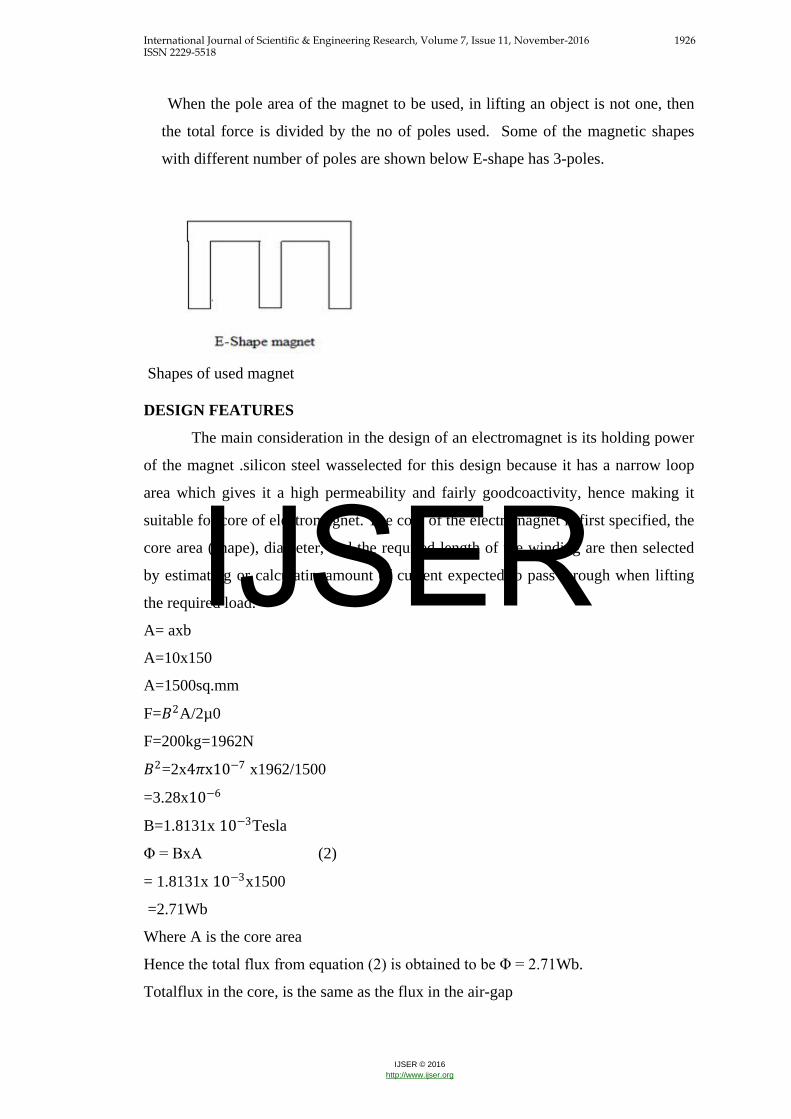
When the pole area of the magnet to be used, in lifting an object is not one, then
the total force is divided by the no of poles used. Some of the magnetic shapes
with different number of poles are shown below E-shape has 3-poles.
Shapes of used magnet DESIGN FEATURES
The main consideration in the design of an electromagnet is its holding power
of the magnet .silicon steel wasselected for this design because it has a narrow loop
area which gives it a high permeability and fairly goodcoactivity, hence making it
suitable for core of electromagnet. The core of the electromagnet is first specified, the
core area (shape), diameter, and the required length of the winding are then selected
by estimating or calculatingamount of current expected to pass through when lifting
the required load.
A= axb
A=10x150
A=1500sq.mm
F=𝐵𝐵2A/2µ0
F=200kg=1962N
𝐵𝐵2=2x4𝜋𝜋x10−7 x1962/1500
=3.28x10⁻⁶
B=1.8131x 10⁻³Tesla
Φ = BxA (2)
= 1.8131x 10−3x1500
=2.71Wb
Where A is the core area
Hence the total flux from equation (2) is obtained to be Φ = 2.71Wb.
Totalflux in the core, is the same as the flux in the air-gap
IJSER
International Journal of Scientific & Engineering Research, Volume 7, Issue 11, November-2016 1927 ISSN 2229-5518
IJSER © 2016 http://www.ijser.org
The magnetizing strength (H) in the air-gap is given by
H = B/µo-(3)
Therefore
H=1.8131x 10⁻³/4𝜋𝜋x10−7
H=1442.81 AT/mm
For the air-gap of 25mm the magneto-motive force (mmf) is given by
AT = HxL = 1442.81x1mm =1442.81AT -(4)
L is the length of air-gap specified as 1mm
This magneto-motive force is the product of the current that will go round the magnet
and the number of turns of thewire that make up the magnet. If one of the variable is
chosen the other variable can be calculated, thus SWG of the conductor is choosen 28
then the current in the electromagnet is 0.35A therefore the no. of turn is given by;
I=MMF/N
N=1442.81/0.35
N=4122 turns-(5)
Finally,
The holding power or force of the magnet is computed using equation (1.0) as
200Kg=1962N - (6)
The maximum operating voltage and the current are determined by the wire
used to create the magnetic field.
APPENDIX B
IJSER
International Journal of Scientific & Engineering Research, Volume 7, Issue 11, November-2016 1928 ISSN 2229-5518
IJSER © 2016 http://www.ijser.org
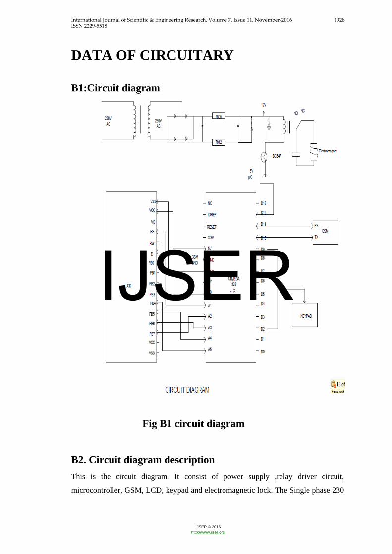
DATA OF CIRCUITARY
B1:Circuit diagram
Fig B1 circuit diagram
B2. Circuit diagram description
This is the circuit diagram. It consist of power supply ,relay driver circuit,
microcontroller, GSM, LCD, keypad and electromagnetic lock. The Single phase 230
IJSER
International Journal of Scientific & Engineering Research, Volume 7, Issue 11, November-2016 1929 ISSN 2229-5518
IJSER © 2016 http://www.ijser.org
v AC supply is given to the step down transformer(230/15 v). The 15v ac is rectified
by using bridge rectifier, we get 5v and 12v dc supply. This output 5v dc is given to
microcontroller. Which further given to relay driver circuit. The 12v dc is given to
electromagnetic lock through the relay driver circuit.
The 5v from relay driver circuit is given to microcontroller digital pin D12. The D10-
D11 is connected to Tx and Rx pin of GSM resp. The digital pin D02-D09 connected
to keypad.
The analog pin of microcontroller is connected to LCD. VCC of LCD is connected to
5v of microcontroller. Ground of each circuit is connected together.
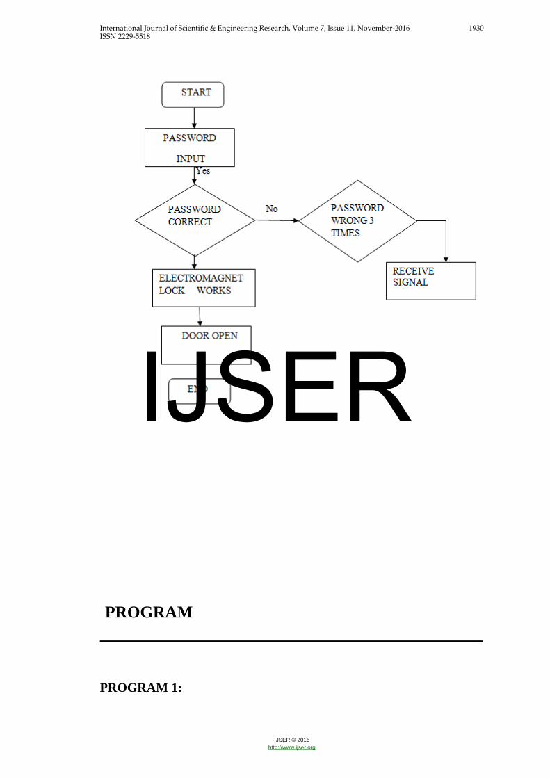
FLOWCHART
IJSER
International Journal of Scientific & Engineering Research, Volume 7, Issue 11, November-2016 1930 ISSN 2229-5518
IJSER © 2016 http://www.ijser.org
PROGRAM
PROGRAM 1:
IJSER

International Journal of Scientific & Engineering Research, Volume 7, Issue 11, November-2016 1931 ISSN 2229-5518
IJSER © 2016 http://www.ijser.org
/*
Blink
Turns on an LED on for one second, then off for one second, repeatedly.
*/
// the setup function runs once when you press reset or power the board
void setup() {
// initialize digital pin 13 as an output.
pinMode(13, OUTPUT);
}
// the loop function runs over and over again forever
void loop() {
digitalWrite(13, HIGH); // turn the LED on (HIGH is the voltage level)
delay(1000); // wait for a second
digitalWrite(13, LOW); // turn the LED off by making the voltage LOW
delay(1000); // wait for a second
}
Program 2 /*
SMS receiver
This sketch, for the Arduino GSM shield, waits for a SMS message
IJSER

International Journal of Scientific & Engineering Research, Volume 7, Issue 11, November-2016 1932 ISSN 2229-5518
IJSER © 2016 http://www.ijser.org
and displays it through the Serial port.
Circuit:
* GSM shield attached to and Arduino
* SIM card that can receive SMS messages
*/
// include the GSM library
#include <GSM.h>
// PIN Number for the SIM
#define PINNUMBER ""
// initialize the library instances
GSM gsmAccess;
GSM_SMS sms;
// Array to hold the number a SMS is retreived from
char senderNumber[20];
void setup()
{
// initialize serial communications and wait for port to open:
Serial.begin(9600);
while (!Serial) {
; // wait for serial port to connect. Needed for Leonardo only
}
Serial.println("SMS Messages Receiver");
// connection state
booleannotConnected = true;
// Start GSM connection
IJSER

International Journal of Scientific & Engineering Research, Volume 7, Issue 11, November-2016 1933 ISSN 2229-5518
IJSER © 2016 http://www.ijser.org
while (notConnected)
{
if (gsmAccess.begin(PINNUMBER) == GSM_READY)
notConnected = false;
else
{
Serial.println("Not connected");
delay(1000);
}
}
Serial.println("GSM initialized");
Serial.println("Waiting for messages");
}
void loop()
{
char c;
// If there are any SMSs available()
if (sms.available())
{
Serialprintln("Message received from:");
// Get remote number
sms.remoteNumber(senderNumber, 20);
Serial.println(senderNumber);
// An example of message disposal
// Any messages starting with # should be discarded
if (sms.peek() == '#')
{
Serial.println("Discarded SMS");
sms.flush();
IJSER
International Journal of Scientific & Engineering Research, Volume 7, Issue 11, November-2016 1934 ISSN 2229-5518
IJSER © 2016 http://www.ijser.org
}
// Read message bytes and print them
while (c = sms.read())
Serial.print(c);
Serial.println("\nEND OF MESSAGE");
// Delete message from modem memory
sms.flush();
Serial.println("MESSAGE DELETED");
}
delay(1000);
}
BIBLIOGRAPHY
IEEE Transection: [1] AdamuMurtalaZungeru AN ELECTRONIC DIGITAL COMBINATION LOCK :
A PRECISE AND RELIABLE SECURITY SYSTEM School of Electrical and
IJSER
International Journal of Scientific & Engineering Research, Volume 7, Issue 11, November-2016 1935 ISSN 2229-5518
IJSER © 2016 http://www.ijser.org
Electronics Engineering, University of Nottingham, JalanBroga, 43500 Semenyih,
Selangor DarulEhsan, Malaysia
[2 ]Design, Development and Testing of an Electromagnet for magnetic levitation
System By DahiruSaniShu’aibu and SanusiSaniAdamu Department of Electrical
Engineering Bayero University, Kano Nigeria..
[3]We were used SECO-LARAM Electromagnet lock manual for design part of
electromagnet from reference books.
[4]International Journal of Embedded Systems and Applications (IJESA) Vol.2, No.2,
June 2012 DOI : 10.5121/ijesa.2012.2201 1
Development of Low Cost Private Office Access Control System(OACS) Sadeque
Reza Khan Prime University, Department of Electrical and Electronic Engineering,
Dhaka-1216, Bangladesh .
Journals: [1] Sadeque Reza Khan.International Journal of Embedded Systems and Applications
(IJESA) Vol.2, zo.2, June 2012, Development of Low Cost Private Office Access
Control System(OACS) Prime University, Department of Electrical and Electronic
Engineering,.
[2].International Journal Of Engineering And Computer Science ISSN:2319-7242
Volume 2.
. DESIGN AND CONSTRUCTION OF DOOR LOCKING SECURITY SYSTEM
USING GSM Ushie James Ogri, DonatusEnangBasseyOkwong, AkaisoEtim
Department of Physics, University of Calabars
Books: [1] SECO-LARM U.S.A.IncMannual
16842 Millikan Avenue, Irvine, CA 92606
IJSER