advanced analysis and seismic design of concrete-filled steel tube...
TRANSCRIPT
Advanced Analysis and Seismic Design of Concrete-Filled Steel Tube Structures
Mark D. Denavit1; Jerome F. Hajjar
2; Roberto T. Leon
3; and Tiziano Perea
4
1Design Engineer, Stanley D. Lindsey and Associates, Ltd., Atlanta, GA 30339.
2CDM Smith Professor and Chair, Department of Civil and Environmental
Engineering, Northeastern University, Boston, MA 02115. 3Professor, Department of Civil and Environmental Engineering, Virginia Tech,
Blacksburg, VA 24061. 4Professor, Departamento de Materiales, Universidad Autónoma Metropolitana,
Mexico City, Mexico.
Abstract
This paper will focus on aspects of the advanced analysis and underlying behavior of
composite structures with concrete-filled steel tube (CFT) columns. Through a
detailed examination of the results of a suite of full-scale slender CFT beam-column
tests, insight into the cyclic behavior of such members is gained, specifically
pertaining to local buckling of the steel tube and the plastic hinge length. Modeling
techniques, which capture these behaviors, are introduced and incorporated into a
general purpose distributed plasticity fiber based beam element formulation. The
model is found to be capable of capturing the observed behavior and producing
accurate results.
INTRODUCTION
Advanced analysis models that can faithfully capture the salient features of the
nonlinear response of a structure are crucial to the assessment of seismic behavior and
the development of seismic design recommendations. For example, nonlinear analysis
is central to the FEMA P695 procedure for quantifying seismic performance factors
(FEMA 2009). Fiber based beam finite elements are well suited to concrete-filled
steel tube (CFT) frame structures. Such models provide accurate results as well as
practicality in both model building and computational time. Beam elements
accurately capture both material and geometric nonlinearity. Fiber cross sections with
appropriate uniaxial stress strain models naturally span the range from concrete
dominant to steel dominant members. The calibration and validation of analysis
models draws on both theory and experimental results to ensure that the underlying
behavior has been represented in the most appropriate manner.
In this paper, a set of detailed experiments on full-scale slender CFT beam-columns
and an analysis model specifically calibrated for CFT members are introduced. Then
two aspects of behavior are examined in detail with respect to both the experimental
results and the nonlinear analysis model. Local buckling of the steel tube is examined
first, followed by the plastic hinge length.
Structures Congress 2015 972
© ASCE
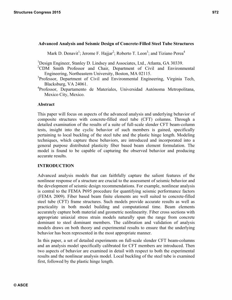
FULL-SCALE SLENDER BEAM-COLUMN TESTS
A series of experiments have been performed on a set of full-scale slender CFT beam-
columns. The specimens in the experimental program were selected to be both
relatively slender in length and in steel tube width-to-thickness ratio. In total, eighteen
specimens were tested with variations in steel tube shape and size, length, and
concrete strength (Table 1).
Table 1. Experimental Text Matrix
Note: In this table, D is the diameter of the circular section, B and H are the width and depth of the rectangular section
respectively, t is the thickness of the steel tube, Fy is the measured yield stress of the steel tube, f´c is the concrete strength at the
testing day, L is the measured length, R is a slenderness parameter (Figure 3), and εlb/εy is the measured strain at initiation of
local buckling normalized by the yielding strain.
The tests were conducted at the Multi-Axial Sub-Assemblage Testing (MAST)
facility at the University of Minnesota. The MAST system (Figure 1) consists of a
stiff steel crosshead connected to 4 vertical actuators and 2 actuators in both
horizontal directions, allowing 6 DOF control of the crosshead. Thick plates were
welded to the ends of the specimens. The bottom plate rigidly connected the specimen
to the strong floor and the top plate rigidly connected the specimen to the crosshead.
Through control of crosshead different end conditions could be simulated, most often
a fixed-free (K=2) condition was enforced.
The specimens were subjected to a variety of successive load cases. The first load
case subjected the specimens to concentric axial load. In this load case, most
specimens were held in a fixed-free (K=2) configuration [specimens 1-C5-18-5 and
18-C5-26-12 were held in a fixed-fixed (K=1) configuration]. Specifically, lateral
forces and bending moments at the crosshead were force controlled to zero, while the
specimen was loaded axially in displacement control until the critical load was
reached. The twist DOF was held in displacement control to zero. Detailed results
from this first load case are reported by Perea et al. (2013).
The second load case subjected the specimens to combined axial compression and
uniaxial bending. This was achieved with vertical force control at a specified load and
D or H B t f' c F y L R εlb / εy
(mm) (mm) (mm) (MPa) (MPa) (mm) (---) (---)
1-C5-18-5 141 --- 3.15 37.9 383 5,499 0.086 14.19
2-C12-18-5 324 --- 5.92 38.6 337 5,499 0.092 n/a
3-C20-18-5 508 --- 5.92 40.0 328 5,525 0.141 5.09
4-Rw-18-5 508 305 7.39 40.7 365 5,537 0.0030 1.64
5-Rs-18-5 508 305 7.39 40.7 365 5,537 0.0065 3.57
6-C12-18-12 324 --- 5.92 91.0 337 5,499 0.092 n/a
7-C20-18-12 508 --- 5.92 91.0 328 5,534 0.141 4.51
8-Rw-18-12 508 305 7.39 91.7 365 5,553 0.0025 1.37
9-Rs-18-12 508 305 7.39 91.7 365 5,553 0.0058 3.16
10-C12-26-5 324 --- 5.92 54.5 335 7,950 0.092 10.74
11-C20-26-5 508 --- 5.92 55.8 305 7,995 0.131 6.61
12-Rw-26-5 508 305 7.39 56.5 406 7,957 0.0026 1.28
13-Rs-26-5 508 305 7.39 57.2 383 7,969 0.0075 3.92
14-C12-26-12 324 --- 5.92 80.0 383 7,963 0.105 8.10
15-C20-26-12 508 --- 5.92 80.0 293 7,976 0.126 6.35
16-Rw-26-12 508 305 7.39 80.7 381 7,957 0.0023 1.21
17-Rs-26-12 508 305 7.39 80.7 380 7,963 0.0062 3.26
18-C5-26-12 141 --- 3.15 80.7 383 7,941 0.086 n/a
Specimen
Structures Congress 2015 973
© ASCE

displacement control of the lateral DOFs. Again, most specimens were held in a
fixed-free (K=2) configuration with bending moments at the crosshead were force
controlled to zero [specimens 1-C5-18-5 and 18-C5-26-12 were held in a fixed-fixed
(K=1) configuration]. The third load case maintained the same control as the second
load case, but subjected the specimen to combined axial compression and biaxial
bending. Detailed results from the second and third load cases are reported by Perea
et al. (2014).
(a) Specimen 1-C5-18-5 Before Testing
(b) Specimen 1-C5-18-5 During Testing
Figure 1. Specimen 1-C5-18-5 in the MAST Facility
Additional latter load cases were conducted, subjecting the specimens to torsion or
alternate end conditions. Full details of the test program including these load cases
and discussions on wet concrete effects are presented elsewhere (Perea 2010; Perea et
al. 2013, 2014).
MIXED BEAM FINITE ELEMENT FORMULATION
Frame analyses using distributed plasticity beam elements strike a favorable balance
of computational efficiency and accuracy. Additionally, mixed formulations (defined
here as treating both element displacements and stress resultants as primary state
variables) allow for accurate modeling of both geometric and material nonlinearities.
Tort and Hajjar (2010b) developed a three-dimensional mixed beam element for the
analysis of composite frames that include rectangular concrete-filled steel tube
members. This finite element was adapted and further validated against an additional
sets of experimental tests on circular concrete-filled steel tube members (Denavit and
Hajjar 2012).
The formulation relies on accurate constitutive relations to achieve accurate results.
Numerous uniaxial constitutive relations have been proposed for composite members
(e.g., Sakino et al. 2004). Typically, the relations are unique to the member shape
(circular, rectangular, etc.) because of differences in behavior, namely different
confinement of the concrete and different susceptibility to local buckling (which is
Structures Congress 2015 974
© ASCE

often modeled as a material response). Different models use different assumptions
and methods of calibration, but they generally strive to mimic the response of short
concentrically loaded columns.
As part of the mixed beam formulation, a family of accurate uniaxial cyclic material
models have been developed and reported by Tort and Hajjar (2010a) for RCFTs and
Denavit and Hajjar (2012) for CCFTs. The constitutive relation for the concrete core
is adapted from the rule-based model of Chang and Mander (1994). The tensile
branch and the cyclic rules were used without changes. However, the compressive
branch was altered to reflect the state of confinement existing in the composite
members. The steel model is based on the bounding-surface plasticity model of Shen
et al. (1995). Several modifications were made to model the behavior of the cold
formed steel tubes in CFT sections, including modifications to allow for the modeling
of local buckling as will be discussed in the following section.
To validate the models, hundreds of comparative analyses were performed (Denavit
and Hajjar 2012, 2014; Tort and Hajjar 2010a). Sets of experimental data covering a
wide variety of material properties, geometric properties, and loading configurations
assembled. The slender beam-column tests described in the previous section were
included in the validation study.
LOCAL BUCKLING OF THE STEEL TUBE
Under compressive stress, the steel tube of a CFT member is susceptible to local
buckling. Due to the presence of the concrete core, the steel tube only has the ability
to buckle outward. In a detailed analysis with continuum or shell elements, local
buckling behavior can be captured explicitly. In frame analyses with beam elements,
this behavior can only be accounted for implicitly in the material constitutive relation.
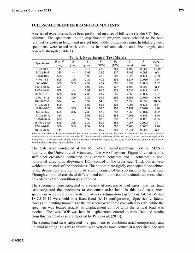
As mentioned in the previous section, the stress-strain constitutive model for steel
adopted in this work is based on a bounding surface plasticity model. To account for
local buckling the model is modified to consist of three regions in compression
(Figure 2). The first region is the unmodified Shen et al. (1995) model, beginning
with elastic behavior then continuing into plasticity. The second region is commences
after the initiation of local buckling, which is assumed to be occur when the
compressive strain reaches a prescribed value, εlb. In this region the response from the
plasticity model is overridden by linear strength degradation with a prescribed
modulus, Kslb. The third region is a constant ultimate residual stress, Fulb. Further
rules and modifications are necessary to properly model the local buckling response
under cyclic loading (Denavit and Hajjar 2014).
In the steel constitutive relation, the strain at which local buckling initiates, εlb, is
taken as a function of a measure of tube slenderness (Figure 3). The function was
calibrated to experimental data found in the literature where initiation of local
buckling was clearly identifiable or was noted by the author in the original reporting
(Denavit and Hajjar 2012; Tort and Hajjar 2010a). This data is denoted in Figure 3 as
the “calibration data” and is shown with grey markers. Comparable experimental data
from the slender beam-column tests discussed in this paper (but not used in the
Structures Congress 2015 975
© ASCE
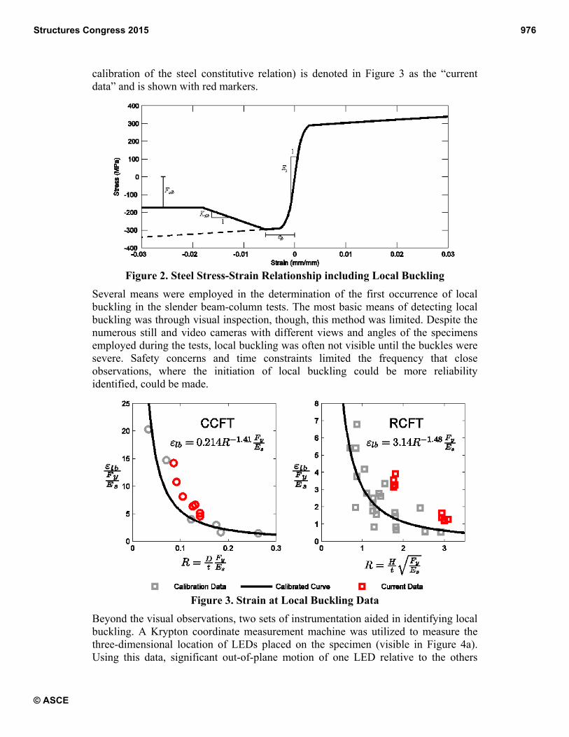
calibration of the steel constitutive relation) is denoted in Figure 3 as the “current
data” and is shown with red markers.
Figure 2. Steel Stress-Strain Relationship including Local Buckling
Several means were employed in the determination of the first occurrence of local
buckling in the slender beam-column tests. The most basic means of detecting local
buckling was through visual inspection, though, this method was limited. Despite the
numerous still and video cameras with different views and angles of the specimens
employed during the tests, local buckling was often not visible until the buckles were
severe. Safety concerns and time constraints limited the frequency that close
observations, where the initiation of local buckling could be more reliability
identified, could be made.
Figure 3. Strain at Local Buckling Data
Beyond the visual observations, two sets of instrumentation aided in identifying local
buckling. A Krypton coordinate measurement machine was utilized to measure the
three-dimensional location of LEDs placed on the specimen (visible in Figure 4a).
Using this data, significant out-of-plane motion of one LED relative to the others
Structures Congress 2015 976
© ASCE

wou
in t
heig
buc
spe
The
Tab
nor
spe
bea
alon
prio
“ca
slen
exp
The
init
mo
sim
The
resu
of e
colu
whi
asp
wit
load
buc
com
uld indicate
three locatio
ght of the
ckling. The s
ecimen at wh
e experimen
ble 1 along
rmalized wit
ecimens for
am-column t
ng with the
or experimen
alibration da
nder beam-c
pression, ind
e reason for
tiation of lo
ments in th
mply random
(a) Spe
Figure
e ability to m
ults, especia
experimenta
umn specim
ich includes
pects of the
thout local b
d in the an
ckling as d
mpression =
local buckl
ons around
specimens.
strain gages
hich the loca
ntally obtain
g with the
th respect to
which local
tests is also
empirical e
ntal data use
ata” with gre
column tests
dicating that
the discrep
ocal bucklin
e slender be
variation sin
ecimen 10-C12
4. Local Bu
model local
ally for memb
al and comp
mens is prese
s modeling
constitutive
buckling mo
nalysis with
discussed pr
2,669 kN an
ling. Additio
the perimet
Sharp incre
were also u
al buckling fi
ned strains a
computed t
o the yield
l buckling w
presented in
expression u
ed in the cali
ey markers)
s is consist
local buckli
ancy could
ng, the relat
eam-column
nce the calib
2-26-5
uckling Defo
buckling is
bers under s
utational res
ented. Two
of local bu
relation we
ore accuratel
local buck
reviously. In
nd LC2b wit
onally, strain
ter of the tu
eases in the
used to deter
irst occurred
at initiation
tube slende
strain εy =
was not obs
n Figure 3 a
sed in the c
ibration of th
. The strain
ently higher
ng occurred
be due to d
tively lower
n tests as co
bration data i
ormation at
important a
severe cyclic
sults for one
sets of com
uckling and
ere inactive.
ly matches t
kling is low
n the secon
th axial com
n gages wer
ubes and in
e strain wou
rmine the co
d.
of local buc
erness param
Fy/Es and n
served. The
as “current d
constitutive r
he empirical
n at initial lo
r than pred
d later than p
different met
r axial load
ompared to t
is rather spa
(b) Specim
t the Conclu
s it can have
c loading. In
e of the rect
mputational
one in wh
In the first
the experim
wer, likely d
nd load ca
mpression =
re placed lon
ntermediately
uld also ind
ompressive s
ckling are p
meter, R. T
not given fo
data from
data” with r
relations and
expression
ocal bucklin
icted by the
predicted in t
thods of iden
ds and high
the calibrati
arse and varia
men 8-Rw-18-1
usion of Test
e a strong ef
Figure 5, a
tangular slen
results are s
hich the loca
load case, t
mental results
due to prem
ases (LC2a
1,334 kN) th
ngitudinally
y along the
dicate local
strain in the
presented in
The data is
or the three
the slender
red markers
d the set of
(denoted as
ng from the
e empirical
the loading.
ntifying the
her bending
ion data, or
able.
12
ting
ffect on the
comparison
nder beam-
shown: one
al buckling
the analysis
s. The peak
mature local
with axial
here is little
Structures Congress 2015 977
© ASCE

difference between the two sets of analysis results and both match the experimental
results well. The results start to significantly diverge in the third load case (LC3a with
axial compression = 3,559 kN). In this load case, under higher axial compression and
biaxial loading, local buckling causes severe strength degradation. The state of the
specimen at the conclusion of testing is shown in Figure 4b. The analysis with local
buckling captures this behavior matching the results with good accuracy. The analysis
without local buckling does not capture the strength degradation and yields a poor
comparison.
Figure 5. Comparison of Validation Results – Specimen 8-Rw-18-12
PLASTIC HINGE LENGTH
Regions of beams and columns that experience large inelastic curvatures when
subjected to severe loading are designated plastic hinges. The inelasticity generally
occurs in certain critical locations (e.g., the member ends for reverse curvature
bending) and over a finite length, which is termed the plastic hinge length. The plastic
hinge length has important implications for finite element analyses (Attalla et al.
1994) as well as for design. Distributed plasticity models, such as the one adopted in
this work, track inelasticity throughout the entire length of the element. For strain-
hardening sections, the plastic hinge length develops naturally and can be observed in
analyses. However, for strain-softening sections, to maintain equilibrium, typically
only one section in the element will follow the softening path, while the others simply
unload elastically. The portion of the element over which the softening section is
applicable is dependent on the numerical integration weight assigned to the section
which depends on the number of sections. This causes a loss of objectivity and
Structures Congress 2015 978
© ASCE
computed results vary significantly based on the selected mesh density. This
phenomenon is known as localization.
Localization has been studied in the context of force based beam elements (Coleman
and Spacone 2001; Scott and Fenves 2006; Scott and Hamutcuoglu 2008). Two
general solutions have been proposed, the first is the alteration of the softening slope
of the constitutive relations, and the second is to ensure that the numerical integration
is performed such that the softening effects are distributed along the appropriate
length of the member, i.e., the integration weight assigned to the section which
softens represents the physical plastic hinge length.
Scott and Hamutcuoglu (2008) present a specialized numerical integration scheme
based on Lobatto quadrature but with the ability to prescribe the integration weights
at the element ends. This approach, when implemented in the mixed beam element,
performs very well for many cases, eliminating the mesh dependency associated with
localization. However, the special numerical integration scheme can cause difficulty
in obtaining convergent results. Alternatively, a simple approximate method of
handling localization can be used whereby the mesh density (i.e., number of elements
per member and number of integration points per element) is selected such that the
integration weight implied by Lobatto quadrature of the critical integration point
(section highest moment) is approximately equal to the physical plastic hinge length.
This approach, however, has limitations. Aspects of the physical behavior such as the
moment gradient must be known a priori and often a mesh cannot be selected such
that the region of expected inelasticity is represented by a single integration point or
even a single element. Nonetheless, with an estimation of the physical plastic hinge
length and careful selection of the mesh density, accurate results can be obtained for a
vast majority of practical cases.
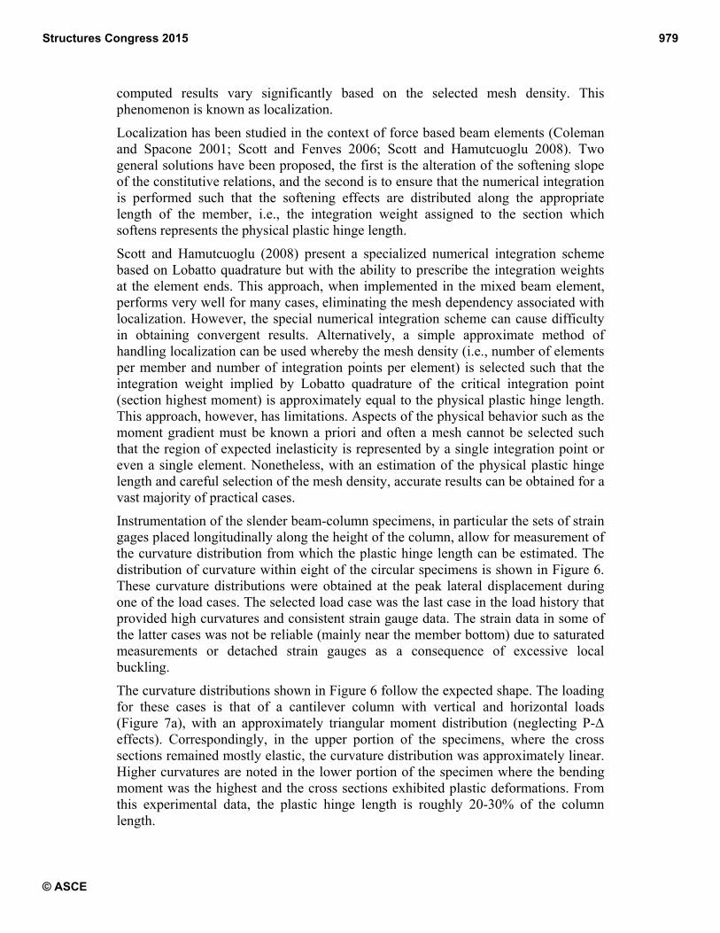
Instrumentation of the slender beam-column specimens, in particular the sets of strain
gages placed longitudinally along the height of the column, allow for measurement of
the curvature distribution from which the plastic hinge length can be estimated. The
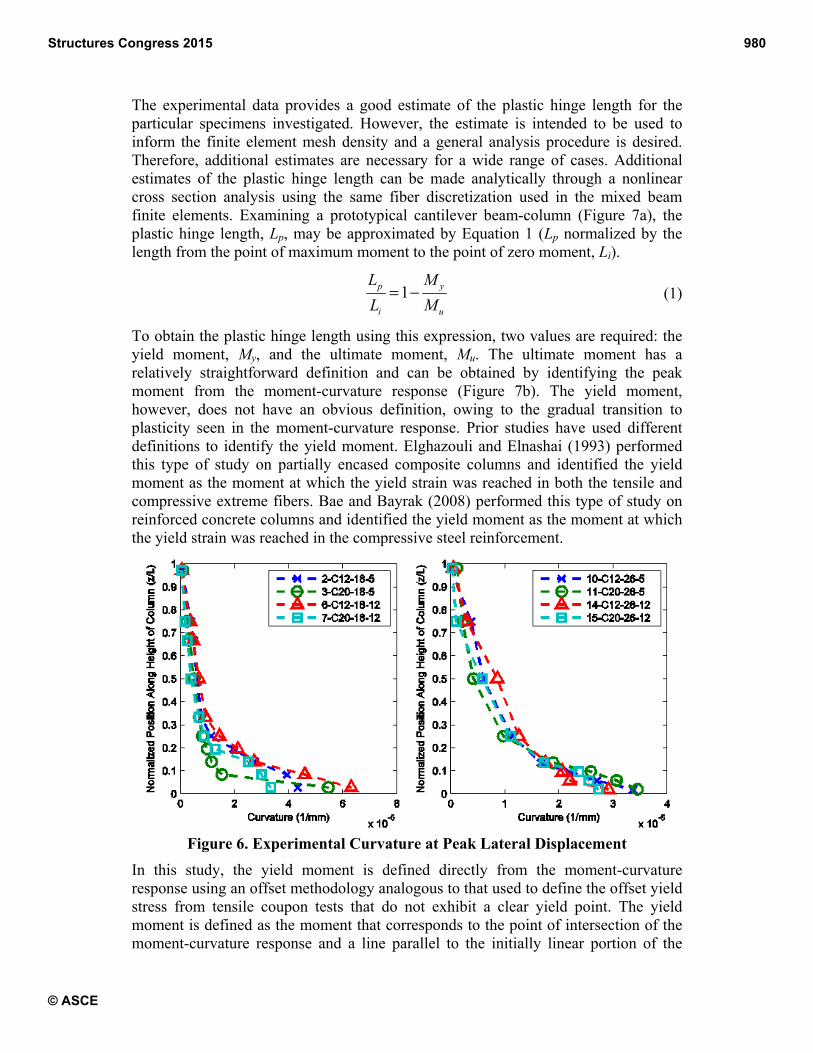
distribution of curvature within eight of the circular specimens is shown in Figure 6.
These curvature distributions were obtained at the peak lateral displacement during
one of the load cases. The selected load case was the last case in the load history that
provided high curvatures and consistent strain gauge data. The strain data in some of
the latter cases was not be reliable (mainly near the member bottom) due to saturated
measurements or detached strain gauges as a consequence of excessive local
buckling.
The curvature distributions shown in Figure 6 follow the expected shape. The loading
for these cases is that of a cantilever column with vertical and horizontal loads
(Figure 7a), with an approximately triangular moment distribution (neglecting P-ǻ
effects). Correspondingly, in the upper portion of the specimens, where the cross
sections remained mostly elastic, the curvature distribution was approximately linear.
Higher curvatures are noted in the lower portion of the specimen where the bending
moment was the highest and the cross sections exhibited plastic deformations. From
this experimental data, the plastic hinge length is roughly 20-30% of the column
length.
Structures Congress 2015 979
© ASCE
The experimental data provides a good estimate of the plastic hinge length for the
particular specimens investigated. However, the estimate is intended to be used to
inform the finite element mesh density and a general analysis procedure is desired.
Therefore, additional estimates are necessary for a wide range of cases. Additional
estimates of the plastic hinge length can be made analytically through a nonlinear
cross section analysis using the same fiber discretization used in the mixed beam
finite elements. Examining a prototypical cantilever beam-column (Figure 7a), the
plastic hinge length, Lp, may be approximated by Equation 1 (Lp normalized by the
length from the point of maximum moment to the point of zero moment, Li).
1p y
i u
L M
L M= − (1)
To obtain the plastic hinge length using this expression, two values are required: the
yield moment, My, and the ultimate moment, Mu. The ultimate moment has a
relatively straightforward definition and can be obtained by identifying the peak
moment from the moment-curvature response (Figure 7b). The yield moment,
however, does not have an obvious definition, owing to the gradual transition to
plasticity seen in the moment-curvature response. Prior studies have used different
definitions to identify the yield moment. Elghazouli and Elnashai (1993) performed
this type of study on partially encased composite columns and identified the yield
moment as the moment at which the yield strain was reached in both the tensile and
compressive extreme fibers. Bae and Bayrak (2008) performed this type of study on
reinforced concrete columns and identified the yield moment as the moment at which
the yield strain was reached in the compressive steel reinforcement.
Figure 6. Experimental Curvature at Peak Lateral Displacement
In this study, the yield moment is defined directly from the moment-curvature
response using an offset methodology analogous to that used to define the offset yield
stress from tensile coupon tests that do not exhibit a clear yield point. The yield
moment is defined as the moment that corresponds to the point of intersection of the
moment-curvature response and a line parallel to the initially linear portion of the
Structures Congress 2015 980
© ASCE

response. The slope of the parallel line is taken as the secant stiffness from zero
moment to 45% of the ultimate moment. The offset is the distance between the origin
of the moment-curvature response and the point of intersection of the parallel line and
the zero moment axis. The offset is expressed in terms of curvature and is taken as
0.001/D, where D is the overall section depth. This value was selected based on
inspection of results from typical composite cross sections as the point at which the
initiation of significant plastic deformations typically occurred.
Figure 7. Schematic of Plastic Hinge Length Methodology and Results
Structures Congress 2015 981
© ASCE

The plastic hinge length obtained from this methodology will vary with the given
cross section as well as the applied axial load. Thus, a parametric study was
performed to document the variation of the plastic hinge length with material,
geometric, and loading properties. Five circular HSS sections (HSS177.8×12.7,
HSS254×12.7, HSS323.9×9.5, HSS406.4×6.4, and HSS609.6×3.2) were selected to
span the range of permissible steel ratios and three concrete strengths (fƍc = 27.6, 55.2,
and 110.3 MPa) were selected for a total of 15 circular CFT cross sections. Steel yield
strength was taken as the typical nominal value (Fy = 290 MPa). A moment-curvature
analysis was performed for each cross section and for compressive axial loads
ranging from zero to 50% of the cross section capacity, Pno, identifying My and Mu for
each analyses to determine Lp/Li. Results are shown in Figure 7c. The results show
that the plastic hinge length varies with steel ratio, concrete strength and axial load.
The greatest variations occur with axial load for the more concrete dominant sections.
The analysis results match generally well with the experimental results which
indicated a value of Lp/Li between 0.2 and 0.3.
CONCLUSIONS
Two aspects of the behavior of concrete filled steel tube beam columns were
discussed. The aspects were highlighted in the context of both a set of experimental
results and a nonlinear analysis formulation. Local buckling of the steel tube was
identified as a cause of significant strength degradation and a challenging but crucial
phenomenon to model. The plastic hinge length was identified as of key importance
in mitigating the deleterious effects of localization. Estimates of the plastic hinge
length, which may be used when selecting a finite element mesh, were made using
both the experimental data and analysis results.
ACKNOWLEDGMENTS
This material is based upon work as part of a NEESR project supported by the
National Science Foundation under Grant No. CMMI-0619047, the American
Institute of Steel Construction, the Georgia Institute of Technology, and the
University of Illinois at Urbana-Champaign. Any opinions, findings, and conclusions
expressed in this material are those of the authors and do not necessarily reflect the
views of the National Science Foundation or other sponsors.
REFERENCES
Attalla, M. R., Deierlein, G. G., and McGuire, W. (1994). “Spread of Plasticity:
Quasi-Plastic-Hinge Approach.” Journal of Structural Engineering, ASCE,
120(8), 2451–2473.
Bae, S., and Bayrak, O. (2008). “Plastic Hinge Length of Reinforced Concrete
Columns.” ACI Structural Journal, 105(3), 290–300.
Chang, G. A., and Mander, J. B. (1994). Seismic Energy Based Fatigue Damage
Analysis of Bridge Columns: Part I - Evaluation of Seismic Capacity. National
Center for Earthquake Engineering Research, Department of Civil
Engineering, State University of New York at Buffalo, Buffalo, New York.
Structures Congress 2015 982
© ASCE

Coleman, J., and Spacone, E. (2001). “Localization Issues in Force-Based Frame
Elements.” Journal of Structural Engineering, ASCE, 127(11), 1257–1265.
Denavit, M. D., and Hajjar, J. F. (2012). “Nonlinear Seismic Analysis of Circular
Concrete-Filled Steel Tube Members and Frames.” Journal of Structural
Engineering, ASCE, 138(9), 1089–1098.
Denavit, M. D., and Hajjar, J. F. (2014). Characterization of Behavior of Steel-
Concrete Composite Members and Frames with Applications for Design.
Newmark Structural Laboratory Report Series, Newmark Structural
Laboratory Report NSEL-034, University of Illinois at Urbana-Champaign,
Urbana, Illinois.
Elghazouli, A. Y., and Elnashai, A. S. (1993). “Performance of Composite
Steel/Concrete Members under Earthquake Loading. Part II: Parametric
Studies and Design Considerations.” Earthquake Engineering & Structural
Dynamics, 22(4), 347–368.
FEMA. (2009). Quantification of Building Seismic Performance Factors. FEMA
P695, Federal Emergency Management Agency, Washington, D.C.
Perea, T. (2010). “Analytical and Experimental Study on Slender Concrete-Filled
Steel Tube Columns and Beam-Columns.” Ph.D. Dissertation, School of Civil
and Environmental Engineering, Georgia Institute of Technology, Atlanta,
Georgia.
Perea, T., Leon, R. T., Hajjar, J. F., and Denavit, M. D. (2013). “Full-Scale Tests of
Slender Concrete-Filled Tubes: Axial Behavior.” Journal of Structural
Engineering, ASCE, 139(7), 1249–1262.
Perea, T., Leon, R. T., Hajjar, J. F., and Denavit, M. D. (2014). “Full-Scale Tests of
Slender Concrete-Filled Tubes: Interaction Behavior.” Journal of Structural
Engineering, ASCE, 140(9), 04014054.
Sakino, K., Nakahara, H., Morino, S., and Nishiyama, I. (2004). “Behavior of
Centrally Loaded Concrete-Filled Steel-Tube Short Columns.” Journal of
Structural Engineering, ASCE, 130(2), 180–188.
Scott, M. H., and Fenves, G. L. (2006). “Plastic Hinge Integration Methods for Force-
Based Beam--Column Elements.” Journal of Structural Engineering, ASCE,
132(2), 244–252.
Scott, M. H., and Hamutcuoglu, O. M. (2008). “Numerically Consistent
Regularization of Force-Based Frame Elements.” International Journal for
Numerical Methods in Engineering, 76(10), 1612–1631.
Shen, C., Mamaghani, I. H. P., Mizuno, E., and Usami, T. (1995). “Cyclic Behavior
of Structural Steels. II: Theory.” Journal of Engineering Mechanics, ASCE,
121(11), 1165–1172.
Tort, C., and Hajjar, J. F. (2010a). “Mixed Finite-Element Modeling of Rectangular
Concrete-Filled Steel Tube Members and Frames under Static and Dynamic
Loads.” Journal of Structural Engineering, ASCE, 136(6), 654–664.
Tort, C., and Hajjar, J. F. (2010b). “Mixed Finite Element for Three-Dimensional
Nonlinear Dynamic Analysis of Rectangular Concrete-Filled Steel Tube
Beam-Columns.” Journal of Engineering Mechanics, ASCE, 136(11), 1329–
1339.
Structures Congress 2015 983
© ASCE