advanced atp system for improving train traffic density...
TRANSCRIPT

140 TRANSPORTATION RESEARCH RECORD 1314
Advanced ATP System for Improving Train Traffic Density and Control Efficiency
IKUO WATANABE AND TETSUO TAKASHIGE
A new automatic train protection (ATP) system allows railroads to use existing signaling systems effectively. This system can detect a train position continuously with an accuracy of less than 30 m by measuring the rail impedance shunted by train axles. Information such as the distance to the train ahead, speed restriction on switches, and so forth are transmitted to each train. These data, modulated by minimum shift keying (MSK) of the 3 kHz band, are also provided over the track circuit at a speed of 200 bits/sec. A train processor generates a brake pattern corresponding to the braking performance and actuates the brake automatically if the actual train speed is above the calculated value. As substantial information is given on a cab signal display, one train can run behind another at an extremely short interval, and an energy-saving operation can be attained. The function of automatic train operation (ATO) can be added easily. A level crossing is controlled safely on the basis of this train detection method. This system is applicable to any heavy-traffic density railway where various kinds of trains run: a high-speed train, a low-speed one, a freight train, and so forth. This system has much flexibility for its introduction and a train without a cab signal can be operated by using an existing wayside signal.
Because the crowding of commuter trains around the Tokyo area is worsening year after year, Japan Railway (JR) has had to increase the transportation capacity. Constructing a new line or increasing the number of tracks produces satisfactory results, but requires vast money and time. Increasing the train length increases transportation capacity, but it is difficult to extend the station platforms because of the lack of space and the high price of land. As a result, increasing the train traffic density is a more economical way to increase transportation capacity. Traffic density under the current signaling system allows 130 sec for a train to pass through a station. However it is not appropriate to reduce the interval between trains further because of the following:
• The system cannot identify train position continuously using a track circuit from 50 to several hundred meters in length.
• Train speed is controlled in a unit of blocks consisting of one or several track circuits, and the margin allowed for braking in blocks is stored.
By solving these problems, a new automatic train protection (ATP) system using the existing signaling systems can effec-
Signaling Laboratory, Railway Technical Research Institute, 2-8-38, Hikari-cho, Kokubunji-city, Tokyo 185, Japan.
tively reduce the train interval and improve the train traffic density. This system can locate train position continuously by measuring the rail impedance of track circuits shunted by the axles of a train. Train speed is controlled continuously by the digital data transmitted from the ground through track circuits.
CURRENT SIGNALING SYSTEM
The train position is mainly detected with track circuits. The train speed is controlled in a unit of blocks consisting of one or several track circuits. The block length is generally several hundred meters. Only one train is permitted to proceed within the block to ensure its safety. There is a block signal around the entrance to each block that indicates the permitted speed to enter the block by the signal color. For example, as Figure 1 shows, red, yellow, yellow-green, and green respectively correspond to 0 km/hr, 45 km/hr, 65 km/hr, and 90 km/hr.
ATP systems with cab signaling have been introduced on the Shinkansen lines, Yamanote commuter line, and the others to ensure a high degree of safety. Only the speed signal is transmitted to the train processor through the track circuits in this system. The train processor receives the speed signal with antennas and displays it on the panel in the cab. If the actual train speed exceeds the transmitted value, the processor sends a command to apply the brake. If the actual train speed is below the value, the processor automatically stops the application of the brake (l'igure 2).
This ATP system involves some problems. There are several speed signals, for example, 90 km/hr, 65 km/hr, 45 km/ hr, and 0 km/hr. When a train is to be stopped, it must be slowed down below the speed signal indicated in each block. The driver must apply the brake off and on in each block, which gives passengers an uncomfortable ride. Each block length is appropriately selected with a margin and an idle running distance for braking. These distances are stored. Consequently commercial speeds become low and train traffic density cannot be reduced further.
The average track circuit length is about 200 m on the · Yamanote commuter line, so the train position is identified in this unit. The track circuit must be cut to a shorter length to precisely detect the train position. However, a large number of track facilities, including the components for transmitting or receiving, is required to do this, and it also raises the construction cost and disturbs track maintenance work.

Watanabe and Takashige 141
Permitted speed 90km/h
Okm/h
f-0 f-0 f-0 r-o G VG y R
Distance
FIGURE I Blocking system with wayside signals.
Target speed
90km/h
65km/h
45kll/h
Distance
1: ••rrln for braking
i: idle runn ing distance in braklnr
FIGURE 2 ATP system with cab signal.
ADVANCED ATP SYSTEM
Train Interval Control
An outline of the new ATP system is shown in Figure 3. This system consists of ground processors and train processors. The ground processor detects the train positions and transmits the data for controlling the train speed to a train processor. The train processor receives and decodes the data and controls the train's speed.
The train position is continuously detected as shown in Figure 4. The ground processor transmits signals to both the forward track circuit and the backward one at the junction point. The carrier frequencies of 1 kHz band are used (indicated by fl through f4 in Figure 4) . The processor inputs each voltage and current at the point, and the rail impedance shunted by axles of a train is measured by dividing the voltage by the current. The distance from the point to the train is calculated using this impedance. When there is no train in the track circuit, impedance larger than one corresponding to the track circuit length is registered, and the ground processor detects no train in the track circuit.
The ground processor generates such data as the distance to the train ahead or to a target stopping point to stop, or the speed restriction for passing a switch. It transmits the information to each train through the track circuit. These data are modulated by minimum shift keying (MSK). The carrier frequencies of 3 kHz band are used (indicated by Fl or F2 in Figure 4). These frequencies are not the same ones used for train position detection. The transmission speed is 200 bits/ sec. The ground processor first calculates the distance from the junction point to the following train (L2) in the backward track circuit. When there is no train in the track circuit, the distance to the following train is equal to the track circuit length (L2') . Second, the processor calculates the distance from the junction point to the rear end position of the train ahead (Ll ). When there is no train in the forward track circuit, the distance to the train ahead is one transmitted from the forward ground processor. The system can continuously identify the length between the two trains by the sum of each distance (Ll + L2).
The train processor receives the data flowing on the rail through antennas consisting of two inductive coils installed at the front of the train. It generates a braking pattern corre-

142
l
0 I
TRANSPORTATION RESEARCH RECORD 1314
.._ Terret speed
Curve
=
~Carr ier frequency changes
et this Point /Antenna Control Dela
Leve I crossing
Tachocenerator
Curve Current for 1eesur Ing train pos 1 t Ion
~-~-~-~
Ground processor
FIGURE 3 Principle of operation.
L 2 '
L2
LI '
LI
ri- f4: Current for measuring trein position
F l-F2: Current for track-to-train date.
[
Distence to train I (Ll•l2) Speed restriction on switches Seclion identification code the other
FIGURE 4 Principle of train position detection.
sponding to the braking performance and controls the train speed. Hence this system can be applied to any railway where various kinds of trains run: a high-speed train, a low-speed one, a freight train, and so forth. The train processor can detect continuously the rear end of the train ahead, so trains can run at an extremely short interval and an energy-saving operation can be attained by eliminating wasteful braking or acceleration. If the following train enters the same track circuit as the preceding one, it cannot receive the control data because the axles of the preceding train shunt the rail. Then the train processor holds the data just before it enters the circuit, and detects its own position and the distance to the train ahead by using both the data and the output from the tachogenerator. When the preceding train leaves the track circuit, the following one is controlled ordinarily to receive the information transmitted from the ground.
The interface between this ATP system and the interlocking system is realized as follows. The ATP system inputs the information about whether the route ahead is clear from the interlocking system. If the route is clear and the switches to be passed are locked, the train is permitted to proceed up to the rear of the train ahead. If the route is obstructed, the
train is permitted to proceed up to the entrance of the route. Once the route is clear and the train proceeds, the ATP system outputs to the interlocking system information such as locked switches in the route until the train passes over them (Figure 5).
Expansion System Based on a New ATP
This ATP system can detect train position continuously in the whole area of the line, and it can transmit the controlling data of 40 bits to a train 3 times/sec. As a result, many expansion systems can be added.
There is a great deal of level crossing equipment on the commuter lines. This system can decide the accurate position at which to start or stop the warning signals, so that it transmits the timing of the warning to the level crossing equipment and controls it Sitfoly. Fmthnmore , hec.i111se it c.itn detect roughly the approaching train's speed by the change rate of the rail impedance, the constant warning can be given for trains at various speeds.
The train processors have the constant data on the line (for example, curves, grades , insulated rail joint positions, and
Watanabe and Takashige
Brak I nr Curve When
not Secured
Braklnr Curv; when I Route B Is
-------./ Route B Is Secured
FIGURE S Interface with Interlocking.
level crossing positions) and can detect the absolute position of the train by detecting both the change of the carrier frequency at the point of the insulated rail joint and the output from the tachogenerator. The position oflevel crossings, curves, and other information to assist the operator thus can be displayed in real-time on the cathode ray tube in the cab (Figure 3). Furthermore, automatic train operation function can be added to this system as follows:
• A few running patterns are stored in the train processor; • The ground processor selects and issues the best running
pattern to the train processor through the track circuit, depending on whether the train is behind schedule or on time; and
• The train processor controls the train speed by using both the pattern and the absolute position.
This system can be expanded to add the function of trainto-track data transmission. This function is realized when the transmitter is mounted on the train and transmits the data to the ground processor through the track circuit. The data are modulated by frequency shift keying (FSK) of approximately 20 kHz. The transmission speed is 1200 bits/sec. The ground processor can receive the data from the train processor within the 100 m area from the ground receiving point. It receives the train identification number, the condition of the train equipment, and so forth. It can receive much data at the home track circuit where the train stops.
If a train without cab signaling runs in this area, the current signaling system will be retained and its speed controlled with wayside signals. It happens that the wayside signal aspect indicates "stop" in spite of the cab signal aspect indicating "proceed." Therefore, when a train with cab signaling is approaching it, the ground processor knows that the train has the cab signal by using the train-to-track data transmission function and switches off the wayside signal (Figure 6) .
DETECTION OF TRAIN POSI'IJON
Method of Measuring Impedance
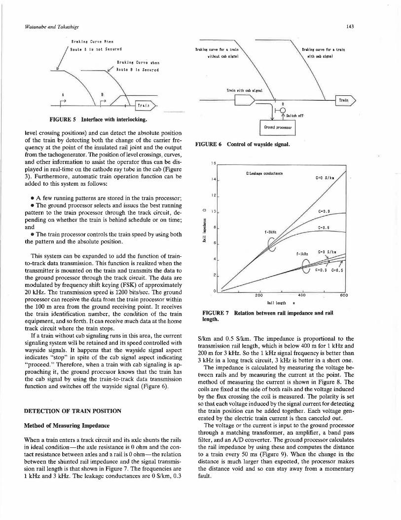
When a train enters a track circuit and its axle shunts the rails in ideal condition-the axle resistance is 0 ohm and the contact resistance between axles and a rail is 0 ohm-the relation between the shunted rail impedance and the signal transmission rail length is that shown in Figure 7. The frequencies are 1 kHz and 3 kHz. The leakage conductances are 0 S/km, 0.3
Braking curve for a train
without cab signal
Ground processor
FIGURE 6 Control of wayside signal.
G:Leakaro conductance 14
12
Rall lensth
Braking curve for • train
with ceb slrnal
G=O S/k1
FIGURE 7 Relation between rail impedance and rail length.
143
S/km and 0.5 S/km. The impedance is proportional to the transmission rail length, which is below 400 m for 1 kHz and 200 m for 3 kHz. So the 1 kHz signal frequency is better than 3 kHz in a long track circuit, 3 kHz is better in a short one.
The impedance is calculated by measuring the voltage between rails and by measuring the current at the point. The method of measuring the current is shown in Figure 8. The coils are fixed at the side of both rails and the voltage induced by the flux crossing the coil is measured. The polarity is set so that each voltage induced by the signal current for detecting the train position can be added together. Each voltage generated by the electric train current is then canceled out.
The voltage or the current is input to the ground processor through a matching transformer, an amplifier, a band pass filter, and an AID converter. The ground processor calculates the rail impedance by using these and computes the distance to a train every 50 ms (Figure 9). When the change in the distance is much larger than expected, the processor makes the distance void and so can stay away from a momentary fault.

144
Electric train current I _,. "" vii I vel
Train ~
vij{j=J,2):Voltege induced
br signal current
vej{j=J, 2): Vol t.,,e induced
br electric train current
~ polaritr
vi2 t -l- v•2
vll+vi2
vel-ve2
Ground processor
FIGURE 8 Measuring of current.
Error Factor in Measuring Train Position
The discrepancy between the measured and the actual distance is caused by various factors. When the impedance measured is smaller than the true one-for example, leakage conductance per unit track circuit length increases-the error is on the safe side. Because the system detects the train position as closer than the actual one, it actuates the following train's brake earlier than it normally would. However, when the impedance measured is larger than the true one, the error is not on the safe side. The following factors cause the unsafe error:
(1) Impedance between axles and rail increases when the rail surface is rusty;
(2) Rail is broken and does not permit the signal current to flow;
(3) Rail bond is worn out or disconnected; (4) Sensor, filter, or amplifier is worn out; and (5) Signal current is mixed with an unbalanced component
of an electric train current .
The voltage between rails shunted by axles of a train is constant when a large voltage is given or an electric current
TRANSPORTATION RESEARCH RECORD 1314
flowing through rails is enlarged. The impedance between axles and rail then becomes small. Figure 10 indicates the relation between voltage given and maximum impedance between axles and rail. The impedance between axles and rail is reduced to less than 0.3 ohm by increasing the voltage given. The relation between the deviation in measuring train position and the impedance between axles and rail is shown in Figure 11. The deviation caused by (1) pn:viuusly mentioned can be rendered smaller than + 20 m by increasing the voltage given.
The deviation caused by (2), (3), or (4) previously mentioned is detected by monitoring the rail impedance of the track circuit when there is no train in the circuit because the impedance becomes larger than the normal one.
The railways in which this system is introduced use direct current. Analyzing the harmonics component of electric train current, the harmonics of 300 Hz-this is the sixth harmonics of the supplied power frequency in east Japan-is a large value. Therefore the error caused by (5) is avoided by using a single frequency different from the harmonics.
Nuober of axles
I oo---0
----..'\
0 2 A,-----..
0.5 - ~r;~ . x Maxi 1u• voltage recei:.\
0. 2 Me.xi1u1 impedance between 2 a axles and re.ii
0. 5
Voltau given V
FIGURE 10 Relation between voltage given and maximum impedance between axle and rail.
tf fi~·bJ 0r·.. In 8 ,..,..,... ,....,.. ....,L ... ,., .. .,....... . l-B
l Attenuator Band pass filter
\ Ampl~flerj ,\.. .. AID converter
I )f ._-:f':_i.::._i...:;,:::...1
Power amplifier
.______[- g:j-G V:Vol lage between rai Is
Signal generator I :Vol lnge induced b)' signnl current
z: Impedance L: Distance
FIGURE 9 Measuring of distance.

Watanabe and Takashige
+4 0
:3 + 20
.2 -;; 0
~ 400 200 600 Zs=O Dis tance [ml
-20
Zs: Impedance between axle and roi I [OJ
- 40
FIGURE 11 Relation between deviation and impedance between axle and rail.
Field Test for Measuring Train Position
The condition of the track circuit changes largely because of the differences in climate and ballast condition. The contacting condition between axles and rail changes is caused by the train weight and operational condition. For these reasons, the field test for measuring train position was repeated over a long time-for 5 years-and the track circuit to be measured was changed. The 1 kHz signal current is superimposed over the current track circuits. The yoltage between rails and the current are applied to the equipment , and these are processed. The equipment produced experimentally for measuring the train position is shown in Figure 12. The block diagram is shown in Figure 9. The equipment shown in Figure 12 measures the train positions in three track circuits that are constructed using fail-safe processors. The duplicated microcomputers operate synchronized by a master clock, and the fail-safe comparator checks that each datum passing the bus is the same. The voltage and the current are applied to the microcomputer every 50 ms. The impedance is calculated by them, and the averaged impedance for 300 ms is accepted into the processor. This average period causes a train position detection error of only 13 m when the train runs at the speed of 90 km/hr. The processor estimates the position of a train axle by using the value. Figure 13 indicates the data measured.
FIGURE 12 Measuring equipment in a signal house.
Total number ot data
+30 - 65 12
Max l1um 6518 6529 I-
11624 116 34
:3 I- Average
8 0 ~ ~ Minimum 100 20 0
I-Distance [ml
I-
- 30 ...
FIGURE 13 Results of a field test measuring train positions (f = 1 kHz).
145
300
The average, minimum, and maximum deviations of distance measured are indicated. The average deviation is a few meters larger in the area close to the transmitting point and is a few meters smaller over a long distance. The deviation exceeds the actual distance over a short distance because the resistance between axles and rail is about 0.2 ohms. The deviation is below the actual distance over a long distance because of the leakage conductance. The maximum deviation is 26 m.
DIGITAL CODED TRACK CIRCUIT
Information Transmitted from Ground to Train Processor
The data for controlling the train speed are transmitted to the train processor by an amplitude-modulated signal to which one frequency is assigned corresponding to the permitted speed in the current ATP system. A large volume of information cannot be transmitted using this method, so only a speed signal is sent. The driver cannot detect the time when the brake is applied.
In this system, the information is given to the train processor as follows:
(1) Distance to a train ahead or a target stopping point in a unit of 20 m;
(2) Speed restriction for passing over a switch; and (3) Section identification code.
Eight check bits of cyclic redundancy check (CRC) code are added to this information. These are transmitted in a prefixed comma-free code. Consequently one frame is composed of 64 bits. The train processor is operated not synchronizing with the ground processor, so this code has the advantage of easily synchronizing the train processor with the data that are transmitted from the ground. This frame is received three times/sec. The transmission speed is 200 bits/sec to meet this requirement. It is advantageous to use as high a carrier frequency as possible to transmit a large volume of information. On the other hand, the information cannot be transmitted to a train over a long distance with a high frequency signal , so a carrier of 3 kHz-used in the current ATP system- is adopted. The system can transmit the information to a train at 600 m away under 0.5 S/km leakage conductance. The power is 40 dBm. The large harmonics of 300 Hz by electric train current appears , so the code is modulated by

146
MSK. This occupies a narrow band and the information can be transmitted without using these harmonics components.
Field Test of Digital Code Transmission
A field test transmitting digital code information to the train through track circuits was done. The equipment shown in Figure 12 transmits the digital coded data to the train. The data format is in a prefixed comma-free code. The transmission speed is 200 bits/sec. Two antennas, as shown in Figure 14, were installed at the front end of the train, and the equipment for decoding the received signal and for logging the data was housed in a box under the floor of the train, as shown in Figure 15. The train processor received a total of about 45 ,000 frames in this field test. It failed to receive the data three times. All of the failed data were detected with CRC. There were no successive mistakes in reception, so it was confirmed to transmit stably digital coded data to a train through the track circuit.
The train processor is operated not synchronizing with the ground processor. It can decode the transmitted data when it receives all bits of the frame, so generally it cannot decode any data of the first received frame when the train enters the track circuit. The average time to decode the received data after entering a track circuit was 0.6 sec; the maximum time was 0.9 sec. Therefore the train processor is to be designed
FIGURE 14 Antennas installed at the front end of a train.
TRANSPORTATION RESEARCH RECORD 1314
FIGURE 15 Decoder and data logger installed in a box unde1· floor of a train.
to keep controlling for 1 sec by using the last received data without receiving the next data.
TRAIN TRAFFIC DENSITY
The traffic density permitted under this system is estimated to be approximately 100 sec considering station stopping time (30 sec), train length (200 m), braking performance (2.5 km/ hr/sec), accelerating performance (2.5 km/hr/sec), train speed at the station entrance (75 km/hr), accuracy of measuring the train position (30 m), and a margin for braking (50 m). As a result, this system can increase the traffic capacity by more than 20 percent.
CONCLUSION
This new ATP system reduces the interval between trains using the track circuits effectively. It is economical and easy to introduce because it uses much of the current signalling system. It can detect the train position continuously and can transmit the control data of t10 bits to a train 3 times/sec. The field test confirmed that these basic functions work stably.
This ATP system can be applied to any heavy traffic density railways where various kinds of trains run, and it has the advantage of not disturbing track maintenance works.