advanced channel modeling (acm)
TRANSCRIPT

Advanced Channel Modeling (ACM) Release 3.40 User Guide
Advanced Channel Modeling (ACM) Release 3.40 – User Guide
www.spirent.com 2
© 2021 Spirent Communications, Inc. All Rights Reserved.
All of the company names and/or brand names and/or product names referred to in this document, in particular, the name “Spirent” and its logo device, are either registered trademarks or trademarks of Spirent plc and its subsidiaries, pending registration in accordance with relevant national laws. All other registered trademarks or trademarks are the property of their respective owners. The information contained in this document is subject to change without notice and does not represent a commitment on the part of Spirent Communications. The information in this document is believed to be accurate and reliable; however, Spirent Communications assumes no responsibility or liability for any errors or inaccuracies that may appear in the document. Page Part Number: 71-009162, Version A0
Advanced Channel Modeling (ACM) Release 3.40 – User Guide
www.spirent.com 3
Table of Contents 1. Introduction ........................................................................................ 6
About Advanced Channel Modeling ..................................................................... 6
What’s New in this Release .................................................................................. 8
System Requirements .......................................................................................... 9
How to Contact Us .............................................................................................. 10
Access the Latest Documentation ...................................................................... 11
Documentation Conventions .............................................................................. 11
2. Managing Scenarios ........................................................................ 12
Overview of the ACM Window ............................................................................ 13
Create Scenarios ................................................................................................ 18
Create a Conducted Scenario .................................................................. 22
Create an OTA Scenario .......................................................................... 24
Create a Phase Matrix Scenario .............................................................. 27
Create a Virtual OTA Scenario ................................................................ 30
Create a Mesh Network Scenario ............................................................ 48
Create a MIMO OTA Scenario ................................................................. 62
Create a SAN Scenario............................................................................ 72
Manage Scenarios .............................................................................................. 79
Open an Existing Scenario ...................................................................... 79
Save a Scenario ...................................................................................... 80
Save an Existing Scenario as a New Scenario ........................................ 80
Manage Base Stations ....................................................................................... 81
Add a Base Station .................................................................................. 81
Modify a Base Station .............................................................................. 83
Delete a Base Station .............................................................................. 83
Using Antenna Settings from a Text File .................................................. 84
Manage Mobile Stations ..................................................................................... 85
Add a Mobile Station ................................................................................ 85
Modify a Mobile Station............................................................................ 87
Delete a Mobile Station ............................................................................ 87
Configure Channels ............................................................................................ 88
Settings to Create the Same Fading Sequence from Run to Run ...................... 93
Preview a Scenario ............................................................................................. 94

Advanced Channel Modeling (ACM) Release 3.40 – User Guide
www.spirent.com 4
Configure the Instruments .................................................................................. 96
Build and Play a Scenario .................................................................................. 98
3. Using Spirent Array Modeling Tool (AMT) ...................................... 107
About Spirent Array Modeling Tool (AMT) ........................................................ 107
Start AMT ......................................................................................................... 108
Configure and Plot an Array ............................................................................. 110
4. ACM Window Components ............................................................ 114
Overview .......................................................................................................... 114
Base Stations tab ............................................................................................. 114
Mobile Stations tab ........................................................................................... 121
Channel Model tab ........................................................................................... 129
Mesh tab ........................................................................................................... 135
Chamber Layout tab ......................................................................................... 136
SAN tab – Sinusoidal scenario ......................................................................... 138
SAN tab – Linear Constant Speed scenario ..................................................... 142
SAN tab – Linear Accelerating Speed scenario ................................................ 146
SAN tab – Elliptical scenario............................................................................. 150
SAN tab – Random Movement scenario .......................................................... 154
SAN tab – Geostationary scenario ................................................................... 159
SAN tab – Field to Lab scenario ....................................................................... 162
SAN tab – GPS scenario .................................................................................. 164
Network Layout tab ........................................................................................... 166
Channel/Path Views tab ................................................................................... 167
Using TDL Channel Models ................................................................... 169
Vertex Connection Setup tab ............................................................................ 172
OTA Setup tab .................................................................................................. 173
Phase Matrix Setup tab .................................................................................... 174
Plots tab ........................................................................................................... 175
Virtual OTA tab ................................................................................................. 176
MIMO OTA Setup tab ....................................................................................... 177
Simulation Builder tab ....................................................................................... 180
Vertex Player tab .............................................................................................. 183
Simulation Builder Status area ......................................................................... 185
Ribbon toolbar .................................................................................................. 186
Do you want to save? dialog box ...................................................................... 187

Advanced Channel Modeling (ACM) Release 3.40 – User Guide
www.spirent.com 5
New Scenario/Save Scenario As dialog box .................................................... 188
Instrument Configuration dialog box ................................................................. 189
Application Password dialog box ...................................................................... 190
Pre-build Report dialog box .............................................................................. 190
Glossary of Terms .................................................................................. 191

Advanced Channel Modeling (ACM) Release 3.40 – User Guide
www.spirent.com 6
1. Introduction
About Advanced Channel Modeling Spirent Advanced Channel Modeling (ACM) Release 3.40 enables you to quickly and easily create highly complicated scenarios without needing to fully understand all the involved channel model propagation characteristics. Simply select the appropriate parameters for the various aspects of the scenario you want to create and then build the desired environment in a few clicks. Using ACM, you can create the following types of scenarios:
• Conducted • OTA (Over the Air), which is an eNodeB/gNodeB OTA test scenario in an
anechoic chamber
• Phase Matrix, which is a massive MIMO test scenario using a Topyoung MIMO Channel System (MCS) phase shifting instrument
• Virtual OTA, which is a “wireless cables” test scenario
• Mesh, which is a mesh network test scenario that can use the following configurations: Full Mesh, Star, Loop, Convoy, and Custom.
NOTE: Custom is not selectable. It appears when you create a mesh configuration that is something other than Full Mesh, Star, Loop, or Convoy.
• SAN, which is a satellite and aeronautical (SAN) scenario for up to four satellites and four observers. ACM provides the following emulation types: Functional test cases (sinusoidal Doppler, linear constant speed, and linear
accelerating speed), Geometrical test cases (elliptical, random movement, and geostationary), and Field to lab (read measured data from an ASCII file or a GPS motion file).
• MIMO OTA, which is a multiple in multiple out (MIMO) over-the-air (OTA) FR2 scenario. In a MIMO OTA scenario, you can enter a different channel model to a probe layout to create a MIMO OTA scenario into an anechoic chamber.
Advanced Channel Modeling (ACM) Release 3.40 – User Guide
www.spirent.com 7
With selected ACM scenarios (such as Conducted, OTA, Phase Matrix, Virtual OTA, and Mesh), you can select from a variety of real-world propagation scenarios, including end-user mobility:
• Circular Motion Basic scenario where one or more devices are moving in a circle around a gNB. This scenario is useful to test beam tracking and beamforming algorithms inside a gNB.
• Linear Motion High-speed scenario with either a train or other vehicle. This scenario allows you to test beamforming, beam tracking, power control, handover, or other algorithms.
• Static Classical performance testing of gNB or end-user devices.
• Piecewise Linear Motion A scenario where a device is moving in a custom pattern that you specify. The Piecewise Linear Motion option uses a text file in which you specify the Cartesian coordinates of every point you want the mobile station to travel in the path and the velocity for each point. There is no limit to the number of segments you specify for a path. This scenario allows you to test beamforming, beam tracking, power control handover, or other algorithms. .
After you design any of these complex 3D propagation scenarios, ACM enables you to automatically create and download channel samples to the Spirent Vertex® channel emulator in accordance with the indicated test environment. ACM produces a text file output that can be used directly in any software simulator. With this capability, you can create realistic field-like tests for early system simulations.
NOTE: Vertex release 4.80.018 or later is required for SAN scenarios and four-Vertex configurations.
Advanced Channel Modeling (ACM) Release 3.40 – User Guide
www.spirent.com 8
What’s New in this Release ACM 3.40 introduces the following new features and enhancements:
• SAN mode, which enables you to configure satellite and aeronautical (SAN) scenarios for up to four satellites and four observers. ACM provides the following emulation types: Functional test cases (sinusoidal Doppler, linear constant speed, and linear
accelerating speed), Geometrical test cases (elliptical, random movement, and geostationary), and Field to lab (read measured data from an ASCII file or a GPS motion file). In a SAN scenario, you can specify the following settings: scenario type (Sinusoidal, Linear Constant Speed, Linear Accelerating
Speed, Elliptical, Random Movement, Geostationary, Field to Lab, or GPS), distance, maximum range, and minimum loss, number of antennas on each satellite (1, 2, or 4), emulation mode (TDD or FDD), downlink carrier frequency, uplink carrier
frequency, and number of antennas for the observer, and channel model. To enter SAN mode and create a SAN scenario, click on SAN in the Connection Type area at the top of the ACM window.
• MIMO OTA mode, which enables you to configure MIMO OTA FR2 scenarios. In a MIMO OTA scenario, you specify the following settings: base station, channel model, and chamber layout (how the probes are located in the chamber). To enter MIMO OTA mode and create a MIMO OTA scenario, click on MIMO OTA in the Connection Type area at the top of the ACM window.
• Support for up to four Vertex units
• Integration with the Spirent Array Modeling Tool (AMT). You can now create and save a library of custom antenna parameters files. The Antenna Parameters Library area on the Base Stations tab and Mobile Stations tab enables you to: Create and save new, custom antenna parameters files. Load, modify, and save custom antenna parameters files that you created
previously. Open a custom antenna parameters file in the Spirent AMT directly from the
ACM GUI. You can also create, modify, load, and save custom antenna parameters files from the Spirent AMT window.

Advanced Channel Modeling (ACM) Release 3.40 – User Guide
www.spirent.com 9
System Requirements The following table lists the minimum and recommended requirements for the PC running ACM 3.40.
Minimum Recommended CPU Intel® i7 dual-core Intel i7 8-core RAM 16GB 32GB Hard Disk 500GB SATA 2TB SSD Operating System Microsoft® Windows® 10 Windows 10

Advanced Channel Modeling (ACM) Release 3.40 – User Guide
www.spirent.com 10
How to Contact Us To obtain technical support for any Spirent Communications product, please contact our Support Services department using any of the following methods: Americas E-mail: [email protected] Web: http://support.spirent.com Toll Free: +1 800-SPIRENT (+1 800-774-7368) (North America) Hours: Monday through Friday, 05:30 to 18:00 Pacific Time Europe, Africa, Middle East E-mail: [email protected] Web: http://support.spirent.com EMEA Phone: +33 (1) 6137 2270 UK Phone: +44 1803 546333 Toll Free Phone: +1 818-676-2616 Hours: Monday through Thursday, 09:00 to 18:00, 9:00 to 17:00 Friday, Paris Time Asia Pacific E-mail: [email protected] Web: http://support.spirent.com In China Mainland Phone: +86 (800) 810-9529 (toll-free) Out of China Mainland Phone: +86 (10) 8233 0033 India Phone: 1800-419-2111 Operating Hours: Monday through Friday, 09:00 to 18:00 Beijing Time The Spirent Knowledge Base (http://support.spirent.com) is designed to serve your technical information needs. The Knowledge Base gives you access to tens of thousands of documents that help answer your network analysis and measurement questions. New content is added daily by Spirent’s communications and networking experts. Sign in with your user ID and password to gain access to additional content that is available only to customers – user manuals, Help files, release notes, Tech Bulletins, and more. When you sign in, you can also use the Knowledge Base to download software and firmware, and to manage your SRs. Information about Spirent Communications and its products and services can be found on the main company website at http://www.spirent.com. Company Address Spirent Communications, Inc. 26750 Agoura Road Calabasas, CA 91302 USA

Advanced Channel Modeling (ACM) Release 3.40 – User Guide
www.spirent.com 11
Access the Latest Documentation The following table lists the documentation related to Spirent Advanced Channel Modeling Release 3.40. You can access these documents from the Spirent Customer Service Center website: http://support.spirent.com.
Document Part Number Spirent Advanced Channel Modeling Release 3.40 System Release Summary
71-009160, Version A0
Spirent Advanced Channel Modeling Release 3.40 User Guide
71-009162, Version A0
To access the latest versions of these documents, perform the following steps: 1. Log into the Spirent Customer Service Center website
(http://support.spirent.com) using the email address and password assigned to you by Spirent.
2. In the Search Knowledge Base box, enter DOC11256 and click on Search KB. The results list appears.
3. Click on Spirent Advanced Channel Modeling Documentation. The Spirent Advanced Channel Modeling Documentation page appears.
4. In the Documentation section, click on the link for the document in which you are interested. The page for the selected document appears.
5. Click on the link in the Attachment area to view the corresponding PDF.
Documentation Conventions This document uses the following conventions:
• Text you type appears in this type style
• Keyboard keys are displayed IN THIS TYPE STYLE

Advanced Channel Modeling (ACM) Release 3.40 – User Guide
www.spirent.com 12
2. Managing Scenarios Using ACM, you can:
• Create a new scenario
• Open an existing scenario
• Save a scenario
• Save an existing scenario as a new scenario
• Manage base stations
• Manage mobile stations
• Configure channels
• Preview a scenario
• Configure the instruments
• Build and play a scenario

Advanced Channel Modeling (ACM) Release 3.40 – User Guide
www.spirent.com 13
Overview of the ACM Window The following figure shows the components of the ACM window.
Figure 1. Components of the ACM window.

Advanced Channel Modeling (ACM) Release 3.40 – User Guide
www.spirent.com 14
The following table describes the components of the ACM window. Table 1. Description of ACM Window Components.
# Component Description 1 Base Stations tab Enables you to configure the settings for up to 16 base
stations. For each base station, you can configure frequency emulation mode, carrier frequency, location coordinates, height of the antenna above ground, transmit power, AWGN and carrier-to-noise ratio level, and antenna parameters such as theta tilt, theta down tilt, phi rotation, antenna pattern, and the configuration of the antenna array. See “Base Stations tab” on page 114 for more information.
NOTE: Mesh network scenarios and SAN scenarios do not contain base stations.
2 Mobile Stations tab Enables you to configure the settings for up to 16 mobile stations. For each mobile station, you can configure motion type, vehicle type, motion repeat type, velocity, distance to be traveled, begin and end coordinates, transmit power, AWGN and carrier-to-noise ratio level, and antenna parameters such as theta down tilt, phi rotation, antenna pattern, and the configuration of the antenna array. See “Mobile Stations tab” on page 121 for more information.
NOTE: MIMO OTA scenarios and SAN scenarios do not contain mobile stations.
3 Channel Model tab Enables you to configure the channel model settings for each channel. A channel ID consists of the base station number and the mobile station number. For each channel ID, you can set downlink status, uplink status, and select either a predefined channel model such as SCME UMi, SCME Uma, High Speed Train, CDL-A, CDL-B, CDL-C, CDL-D, CDL-E, TDL-A, TDL-B, and TDL-C or create and save a custom configuration. In a custom configuration, you configure parameters such as power angle spectrum, street width, average building height, paths and midpaths settings, cluster settings, and scaling factors. See “Channel Model tab” on page 129 for more information.
Advanced Channel Modeling (ACM) Release 3.40 – User Guide
www.spirent.com 15
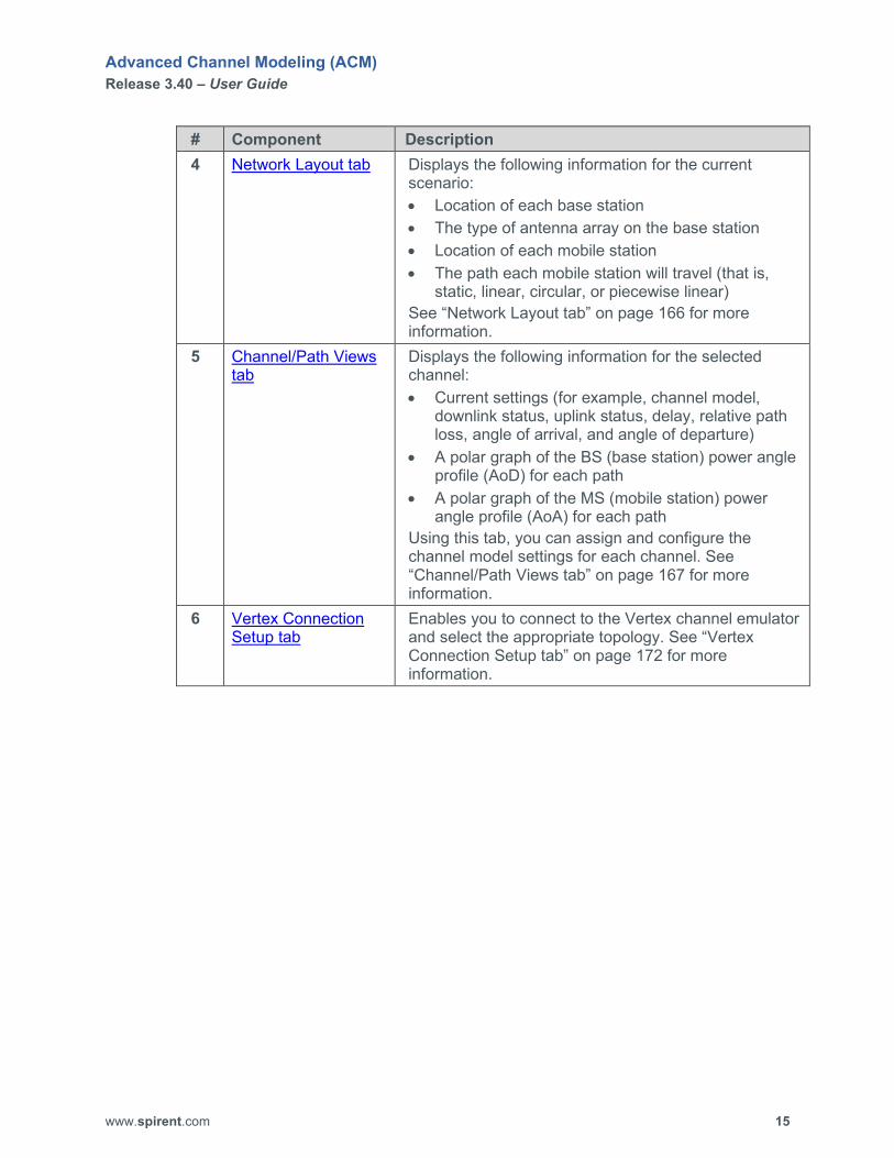
# Component Description 4 Network Layout tab Displays the following information for the current
scenario: • Location of each base station • The type of antenna array on the base station • Location of each mobile station • The path each mobile station will travel (that is,
static, linear, circular, or piecewise linear) See “Network Layout tab” on page 166 for more information.
5 Channel/Path Views tab
Displays the following information for the selected channel: • Current settings (for example, channel model,
downlink status, uplink status, delay, relative path loss, angle of arrival, and angle of departure)
• A polar graph of the BS (base station) power angle profile (AoD) for each path
• A polar graph of the MS (mobile station) power angle profile (AoA) for each path
Using this tab, you can assign and configure the channel model settings for each channel. See “Channel/Path Views tab” on page 167 for more information.
6 Vertex Connection Setup tab
Enables you to connect to the Vertex channel emulator and select the appropriate topology. See “Vertex Connection Setup tab” on page 172 for more information.

Advanced Channel Modeling (ACM) Release 3.40 – User Guide
www.spirent.com 16
# Component Description 7 Plots tab Displays graphs of the following information for each
mobile station used in the current scenario: • Distance (meters) from base station to mobile
station over time • Pathloss (dB) from base station to mobile station
over time • Pathloss (dB) from mobile station to base station
over time • Theta line of sight (LOS) (degrees) from base
station to mobile station over time • Phi LOS (degrees) from base station to mobile
station over time • Theta DOT (degrees) of mobile station over time • Phi DOT (degrees) of mobile station over time • Mobile station height (meters) over time • Doppler LOS (Hz) of mobile station over time • Doppler LOS (Hz) of base station over time • Probability of LOS (%) of mobile station over time See “Plots tab” on page 175 for more information.
8 Ribbon toolbar Displays the options for the selected menu at the top of the ACM window. See “Ribbon toolbar” on page 186 for more information.

Advanced Channel Modeling (ACM) Release 3.40 – User Guide
www.spirent.com 17
# Component Description 9 Simulation Builder
tab Enables you to: • specify the settings for the IQ playback file for the
current scenario file
• enable the Use Dynamic Level Adjustment setting, which allows you to embed the output level and C/N ratio data in the IQ playback data file when AWGN is enabled for the base station(s) and/or mobile station(s). This feature provides a better digital representation of fading while using Vertex RFM to adjust the overall output level.
NOTE: In Mesh mode, you must set Use Dynamic Level Adjustment to No on the Simulation Builder tab. ACM only supports digital gains at this time for mesh network scenarios.
• generate the IQ playback file for the current scenario file
The Preview button enables you to view plots of the scenario before you build the IQ playback file. The Build button enables you to generate the IQ playback file. See “Simulation Builder tab” on page 180 for more information.
10 Vertex Player tab Enables you to: • Connect to the Vertex unit. • Enable Virtual OTA (VOTA) (if you are using the
Virtual OTA connection type) • Apply the VOTA coupling matrix (if you are using
the Virtual OTA connection type). • Download the IQ playback file to the Vertex unit. • Play/pause the IQ playback file on the Vertex unit. See “Vertex Player tab” on page 183 for more information.
11 Simulation Builder Status area
Shows the status of the build process. See “Simulation Builder Status area” on page 185 for more information.

Advanced Channel Modeling (ACM) Release 3.40 – User Guide
www.spirent.com 18
Create Scenarios A scenario is a collection of parameters that model a particular environment. These parameters are stored in a .xml file. When you create a new scenario, a folder with the scenario name is created, and the .xml file is stored in that folder. Using ACM, you can create the following types of scenarios:
• Conducted • OTA (Over the Air), which is an eNodeB/gNodeB OTA test scenario in an
anechoic chamber
• Phase Matrix, which is a massive MIMO test scenario using a Topyoung MIMO Channel System (MCS) phase shifting instrument
• Virtual OTA, which is a “wireless cables” test scenario
• Mesh, which is a mesh network test scenario that can use the following configurations: Full Mesh Star Loop Convoy Custom
NOTE: Custom is not selectable. It appears when you create a mesh configuration that is something other than Full Mesh, Star, Loop, or Convoy.
• SAN, which is a satellite and aeronautical (SAN) scenario for up to four satellites and four observers. ACM provides the following emulation types: Functional test cases (sinusoidal Doppler, linear constant speed, and linear
accelerating speed) Geometrical test cases (elliptical, random movement, and geostationary), and Field to lab (read measured data from an ASCII file or a GPS motion file).
• MIMO OTA, which is a multiple in multiple out (MIMO) over-the-air (OTA) FR2 scenario. In a MIMO OTA scenario, you can enter a different channel model to a probe layout to create a MIMO OTA scenario into an anechoic chamber.

Advanced Channel Modeling (ACM) Release 3.40 – User Guide
www.spirent.com 19
Before creating a scenario, you should determine:
• the number of base stations you want to use and the settings for each base station. You can have a maximum of 16 base stations. You must have at least 1 base station.
NOTE: Mesh network scenarios and SAN scenarios do not contain base stations. The base station settings include: frequency emulation mode (FDD or TDD) carrier frequency location of each base station and the height of the transmitter on each base
station. (The height of the transmitter is the height above the ground.) antenna parameters such as theta tilt, theta down tilt, antenna pattern, and #
of rows and # of columns (which defines the configuration of the antenna array)
• the number of mobile stations you want to use and the settings for each mobile station. You can have a maximum of 16 mobile stations. You must have at least 1 mobile station.
NOTE: MIMO OTA network scenarios and SAN scenarios do not contain mobile stations. These mobile station settings include: Motion type for the mobile station (static, linear motion, circular motion, or
piecewise linear motion) Starting point and ending point for the mobile station (if using linear or circular
motion) Velocity of the mobile station (if using linear or circular motion) Rotation of the mobile station (if using circular motion). A mobile station can
rotate either clockwise or counter clockwise. Antenna parameters such as theta tilt, antenna pattern, and the number of
rows and the number of columns (which defines the configuration of the antenna array)
• the channel model you want to use for each channel. ACM provides the following preconfigured channel models: SCME UMi SCME UMa High Speed Train CDL-A CDL-B CDL-C

Advanced Channel Modeling (ACM) Release 3.40 – User Guide
www.spirent.com 20
CDL-D CDL-E TDL-A TDL-B TDL-C ACM also provides the “Custom” model, which enables you to configure and save a custom channel model. If you select this option, you must specify the settings such as power angle spectrum, use model, street width, path settings, and midpath settings. To save your custom channel model, click the Customize button on the Channel/Path Views tab. Using the Customize button, you can create a library of custom channel models. To access your custom channel models, select Custom from the Channel Model box on the Channel Model tab and click the Load button on the Channel/Path Views tab. Custom path loss models are supported.
Depending on the type of scenario, you must perform the following steps to create a scenario: 1. Create a new scenario file and save it. 2. Specify the scenario/connection type (that is, Conducted, OTA, Phase Matrix,
Virtual OTA, Mesh, MIMO OTA, or SAN). 3. Configure the base stations.
NOTE: Mesh network scenarios and SAN scenarios do not contain base stations.
4. Configure the mobile stations.
NOTE: MIMO OTA network scenarios and SAN scenarios do not contain mobile stations.
5. Configure the channel model. 6. For a MIMO OTA scenario, configure the chamber layout. 7. Verify the channel path views. 8. Select the connection setup for the Vertex unit. 9. Preview the scenario. 10. Build the IQ playback or DEE file. 11. Save the scenario.

Advanced Channel Modeling (ACM) Release 3.40 – User Guide
www.spirent.com 21
After you build an IQ playback file, perform the following steps to play that file on a Vertex unit: 1. Connect to the Vertex unit. 2. Download the IQ playback file from ACM to the Vertex unit. 3. Play the IQ playback file. 4. When finished, disconnect from the Vertex unit.

Advanced Channel Modeling (ACM) Release 3.40 – User Guide
www.spirent.com 22
Create a Conducted Scenario To create a new conducted scenario: 1. Click on the Scenario menu at the top of the Advanced Channel Modeling
window. The Scenario ribbon toolbar appears at the top of the window.
Figure 2. Scenario ribbon toolbar.
2. Click the New button to create a new scenario. The New Scenario dialog box appears.
Figure 3. New Scenario dialog box.
3. In the Name box, type the name of the scenario. By default, scenario files are saved to C:\ProgramData\Spirent Communications\Advanced Channel Modeling\Scenarios. If you want to change the location where you want to save the new scenario file, use the Browse button specify the location where you want to save the new scenario file. The folder C:\ProgramData may be hidden in the Windows file system. If you are unable to see the folder C:\ProgramData, perform the following steps: a. Click Windows Start button, type folder options in the associated text box,
and press the ENTER key. The File Explorer Options dialog box appears.
b. Click on the View tab. c. In the Advanced settings list box, click on the Show hidden files, folders,
and drives option button. d. Click the OK button.
Advanced Channel Modeling (ACM) Release 3.40 – User Guide
www.spirent.com 23
4. Click the OK button. The title you entered appears at the top of the ACM window.
NOTE: You MUST save your new scenario file before you can build it. By default, any new scenarios you create are Conducted.
5. Configure the base station(s). See “Manage Base Stations” on page 81. 6. Configure the mobile stations. See “Manage Mobile Stations” on page 85. 7. Configure the channels. See “Configure Channels” on page 88. 8. Save your changes. See “Save a Scenario” on page 80.

Advanced Channel Modeling (ACM) Release 3.40 – User Guide
www.spirent.com 24
Create an OTA Scenario Perform this procedure to create an eNodeB/gNodeB OTA test scenario in an anechoic chamber. To create a new OTA scenario: 1. Click on the Scenario menu at the top of the Advanced Channel Modeling
window. The Scenario ribbon toolbar appears at the top of the window.
Figure 4. Scenario ribbon toolbar.
2. Click the New button to create a new scenario. The New Scenario dialog box appears.
Figure 5. New Scenario dialog box.
3. In the Name box, type the name of the scenario. By default, scenario files are saved to C:\ProgramData\Spirent Communications\Advanced Channel Modeling\Scenarios. If you want to change the location where you want to save the new scenario file, use the Browse button specify the location where you want to save the new scenario file. The folder C:\ProgramData may be hidden in the Windows file system. If you are unable to see the folder C:\ProgramData, perform the following steps: a. Click Windows Start button, type folder options in the associated text box,
and press the ENTER key. The File Explorer Options dialog box appears.
b. Click on the View tab. c. In the Advanced settings list box, click on the Show hidden files, folders,
and drives option button. d. Click the OK button.

Advanced Channel Modeling (ACM) Release 3.40 – User Guide
www.spirent.com 25
4. Click the OK button. The title you entered appears at the top of the ACM window.
NOTE: You MUST save your new scenario file before you can build it.
5. In the Connection Type area on the Scenario ribbon toolbar, click on OTA. 6. Click the Save button on the Scenario ribbon toolbar. 7. Configure the base station(s). See “Manage Base Stations” on page 81.
NOTE: For an OTA scenario, you can configure only 1 base station.
8. Configure the mobile stations. See “Manage Mobile Stations” on page 85. 9. Configure the channels. See “Configure Channels” on page 88. 10. Click on the OTA Setup tab.
The OTA Setup tab appears.
Figure 6. OTA Setup tab.
Advanced Channel Modeling (ACM) Release 3.40 – User Guide
www.spirent.com 26
Using this tab, you can set the probe geometry and configure the following settings: channel ID associated paths AoD ZoD whether to attenuate unused outputs whether the antenna array location contains 2 slants polarization vector for the antenna array slant
11. From the Method for Setting the Probe Geometry box, select the appropriate probe geometry option. Your choices are From Channel Model, From Network Layout, and Custom.
12. Specify whether you want to attenuate unused outputs. 13. Specify whether the antenna array location contains 2 slants. If it has 2 slants,
set Enable Second Slant to Yes. 14. Specify the polarization vector for the antenna array slant. The left box sets the
polarization vector for the first antenna array slant. The right box sets the polarization vector for the second antenna array slant. The right box is enabled if Enable Second Slant is set to Yes.
15. Save your changes. See “Save a Scenario” on page 80.

Advanced Channel Modeling (ACM) Release 3.40 – User Guide
www.spirent.com 27
Create a Phase Matrix Scenario Perform this procedure to create a massive MIMO test scenario using a Topyoung MIMO Channel System (MCS) phase shifting instrument. To create a new phase matrix scenario: 1. Click on the Scenario menu at the top of the Advanced Channel Modeling
window. The Scenario ribbon toolbar appears at the top of the window.
Figure 7. Scenario ribbon toolbar.
2. Click the New button to create a new scenario. The New Scenario dialog box appears.
Figure 8. New Scenario dialog box.
3. In the Name box, type the name of the scenario. By default, scenario files are saved to C:\ProgramData\Spirent Communications\Advanced Channel Modeling\Scenarios. If you want to change the location where you want to save the new scenario file, use the Browse button specify the location where you want to save the new scenario file. The folder C:\ProgramData may be hidden in the Windows file system. If you are unable to see the folder C:\ProgramData, perform the following steps: a. Click Windows Start button, type folder options in the associated text box,
and press the ENTER key. The File Explorer Options dialog box appears.
b. Click on the View tab. c. In the Advanced settings list box, click on the Show hidden files, folders,
and drives option button. d. Click the OK button.

Advanced Channel Modeling (ACM) Release 3.40 – User Guide
www.spirent.com 28
4. Click the OK button. The title you entered appears at the top of the ACM window.
NOTE: You MUST save your new scenario file before you can build it.
5. In the Connection Type area on the Scenario ribbon toolbar, click on Phase Matrix.
6. Click the Save button on the Scenario ribbon toolbar. 7. Configure the base station(s). See “Manage Base Stations” on page 81. 8. Configure the mobile stations. See “Manage Mobile Stations” on page 85. 9. Configure the channels. See “Configure Channels” on page 88. 10. Click on the Phase Matrix Setup tab.
The Phase Matrix Setup tab appears.
Figure 9. Phase Matrix Setup tab.

Advanced Channel Modeling (ACM) Release 3.40 – User Guide
www.spirent.com 29
Using this tab, you can set the probe geometry and configure the following settings: channel ID associated paths AoD ZoD whether to attenuate unused outputs whether the antenna array location contains 2 slants polarization vector for the antenna array slant.
11. From the Method for Setting the Probe Geometry box, select the appropriate probe geometry option. Your choices are From Channel Model, From Network Layout, and Custom.
12. Specify whether you want to attenuate unused outputs. 13. Specify whether the antenna array location contains 2 slants. If it has 2 slants,
set Enable Second Slant to Yes. 14. Specify the polarization vector for the antenna array slant. The left box sets the
polarization vector for the first antenna array slant. The right box sets the polarization vector for the second antenna array slant. The right box is enabled if Enable Second Slant is set to Yes.
15. Save your changes. See “Save a Scenario” on page 80.

Advanced Channel Modeling (ACM) Release 3.40 – User Guide
www.spirent.com 30
Create a Virtual OTA Scenario The Virtual OTA scenario enables you to use the characteristics measured in an anechoic chamber and run tests outside of the chamber. In a Virtual OTA scenario, ACM uses the antenna pattern file of the DUT from the chamber and calibrates out the cross connections between the radiator (base station) antenna and the antenna of the DUT (mobile station). You can then perform a conducted test that applies the superposition of the radio channel model and the antenna pattern. ACM supports the following Virtual OTA configurations:
• 2x2 configuration
• 4x4 configuration The 2x2 VOTA configuration consists of:
• one base station with two antennas
• one mobile station with two antennas In a 2x2 configuration, ACM mathematically removes:
• the cross connection between antenna 1 of the base station and antenna 2 of the DUT
• the cross connection between antenna 2 of the base station and antenna 1 of the DUT
The result is “wireless cables” between antenna 1 of the base station and antenna 1 of the mobile station and antenna 2 of the base station and antenna 2 of the mobile station. The following figure shows the calibration process for a 2x2 configuration.
Figure 10. Calibration for a 2x2 configuration.
Advanced Channel Modeling (ACM) Release 3.40 – User Guide
www.spirent.com 31
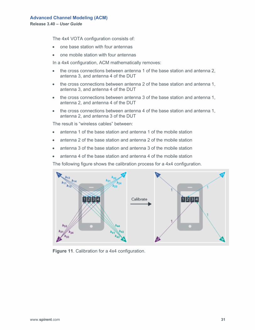
The 4x4 VOTA configuration consists of:
• one base station with four antennas
• one mobile station with four antennas In a 4x4 configuration, ACM mathematically removes:
• the cross connections between antenna 1 of the base station and antenna 2, antenna 3, and antenna 4 of the DUT
• the cross connections between antenna 2 of the base station and antenna 1, antenna 3, and antenna 4 of the DUT
• the cross connections between antenna 3 of the base station and antenna 1, antenna 2, and antenna 4 of the DUT
• the cross connections between antenna 4 of the base station and antenna 1, antenna 2, and antenna 3 of the DUT
The result is “wireless cables” between:
• antenna 1 of the base station and antenna 1 of the mobile station
• antenna 2 of the base station and antenna 2 of the mobile station
• antenna 3 of the base station and antenna 3 of the mobile station
• antenna 4 of the base station and antenna 4 of the mobile station The following figure shows the calibration process for a 4x4 configuration.
Figure 11. Calibration for a 4x4 configuration.

Advanced Channel Modeling (ACM) Release 3.40 – User Guide
www.spirent.com 32
Before creating a Virtual OTA scenario, keep in mind the following information:
• The DUT must support complex antenna pattern reporting so you can measure the antenna pattern in the anechoic chamber.
• A Virtual OTA scenario supports one base station and one mobile station.
• Only downlink paths are supported.
• Only a Vertex unidirectional connection setup is supported.
• If you create a 2x2 VOTA scenario, the Vertex connection setup must have two outputs.
• If you create a 4x4 VOTA scenario, the Vertex connection setup must have four outputs.
To create a VOTA scenario: 1. Click on the Scenario menu at the top of the Advanced Channel Modeling
window. The Scenario ribbon toolbar appears at the top of the window.
Figure 12. Scenario ribbon toolbar.
2. Click the New button to create a new scenario. The New Scenario dialog box appears.
Figure 13. New Scenario dialog box.
Advanced Channel Modeling (ACM) Release 3.40 – User Guide
www.spirent.com 33
3. In the Name box, type the name of the scenario. By default, scenario files are saved to C:\ProgramData\Spirent Communications\Advanced Channel Modeling\Scenarios. If you want to change the location where you want to save the new scenario file, use the Browse button specify the location where you want to save the new scenario file. The folder C:\ProgramData may be hidden in the Windows file system. If you are unable to see the folder C:\ProgramData, perform the following steps: a. Click Windows Start button, type folder options in the associated text box,
and press the ENTER key. The File Explorer Options dialog box appears.
b. Click on the View tab. c. In the Advanced settings list box, click on the Show hidden files, folders,
and drives option button. d. Click the OK button.
4. Click the OK button. The title you entered appears at the top of the ACM window.
NOTE: You MUST save your new scenario file before you can build it.
5. In the Connection Type area on the Scenario ribbon toolbar, click on Virtual OTA.
6. Click the Save button on the Scenario ribbon toolbar.

Advanced Channel Modeling (ACM) Release 3.40 – User Guide
www.spirent.com 34
7. In the Parameters area, click on the Base Stations tab. The Base Stations tab appears.
Figure 14. Base Stations tab.

Advanced Channel Modeling (ACM) Release 3.40 – User Guide
www.spirent.com 35
8. From the ID dropdown box, select the base station you want to use.
NOTE: For a Virtual OTA scenario, configure only one base station.
9. If you want to customize the name of the base station, type the new name in the Name box.
10. Set Enabled? to Yes. The Frequency, Location, Power, and Antenna Parameters become enabled, and the icon for the base station appears on the Network Layout tab.
11. Perform one of the following steps: If you are configuring a 2x2 configuration, set Number of Rows to 1 and
Number of Columns to 1 in the Antenna Parameters section. If you are configuring a 4x4 configuration, set Number of Rows to 2 and
Number of Columns to 2 in the Antenna Parameters section. 12. Configure the other base station parameters. 13. When you are finished configuring the base station parameters, click on the
Mobile Stations tab. The Mobile Stations tab appears.

Advanced Channel Modeling (ACM) Release 3.40 – User Guide
www.spirent.com 36
Figure 15. Mobile Stations tab.
Advanced Channel Modeling (ACM) Release 3.40 – User Guide
www.spirent.com 37
14. From the ID dropdown box, select the mobile station you want to use.
NOTE: For a Virtual OTA scenario, configure only one mobile station.
15. If you want to customize the name of the mobile station, type the new name in the Name box.
16. Set Enabled? to Yes. The Location, Power, and Antenna Parameters become enabled, and the icon for the mobile station appears on the Network Layout tab.
17. Perform one of the following steps: If you are configuring a 2x2 configuration, set Number of Rows to 1 and
Number of Columns to 1 in the Antenna Parameters section. If you are configuring a 4x4 configuration, set Number of Rows to 2 and
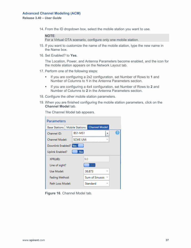
Number of Columns to 2 in the Antenna Parameters section. 18. Configure the other mobile station parameters. 19. When you are finished configuring the mobile station parameters, click on the
Channel Model tab. The Channel Model tab appears.
Figure 16. Channel Model tab.

Advanced Channel Modeling (ACM) Release 3.40 – User Guide
www.spirent.com 38
20. From the Channel ID box, select the channel you want to configure. The Channel Model tab and the Channel/Path Views tab show the settings for the selected channel.
Figure 17. Channel Model tab and Channel/Path Views tab.
21. Set Downlink Enabled? to Yes. 22. Set Uplink Enabled? to No.
The illustration at the top of the Channel/Path Views tab shows a unidirectional path (downlink from the base station to the mobile station).
NOTE: The Virtual OTA scenario supports only unidirectional paths.
23. Configure the other channel model settings. 24. Repeat Steps 20 through 23 for each channel you want to configure. 25. When you are finished configuring the channels, click on the Scenario menu at
the top of the Advanced Channel Modeling window. The Scenario ribbon toolbar appears at the top of the window.
26. Click the Save button. Your changes are saved.
Advanced Channel Modeling (ACM) Release 3.40 – User Guide
www.spirent.com 39
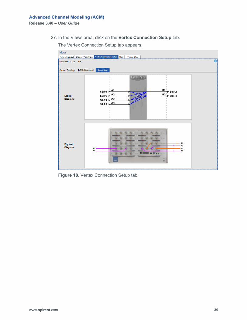
27. In the Views area, click on the Vertex Connection Setup tab. The Vertex Connection Setup tab appears.
Figure 18. Vertex Connection Setup tab.

Advanced Channel Modeling (ACM) Release 3.40 – User Guide
www.spirent.com 40
28. Click the Select New button. The Topology Selector dialog box appears.
Figure 19. Topology Selector tab.
29. Select the appropriate unidirectional topology for the scenario. If you are using a 2x2 VOTA configuration, you must select a unidirectional topology that has 2 outputs. If you are using a 4x4 VOTA configuration, you must select a unidirectional topology that has 4 outputs.
30. Click the Apply button. The logical diagram and physical diagram of the selected topology are displayed on the Vertex Connection Setup tab.
31. Make sure the PC running ACM can connect to your Vertex unit.

Advanced Channel Modeling (ACM) Release 3.40 – User Guide
www.spirent.com 41
32. In the Build & Play area, click on the Vertex Player tab. The Vertex Player tab appears.
Figure 20. Vertex Player tab.
33. Click the Connect button to connect to your Vertex unit and verify that your system has the required hardware to support the scenario. The display area at the bottom of the Vertex Player tab shows the status of the connection process and whether the selected topology is supported by your Vertex unit. If the Vertex unit can support the selected topology, the message New topology loaded successfully appears, and the Instrument Status area on the Vertex Player tab displays the message Connected as shown in the following figure.
Figure 21. Connected message on the Vertex Player tab.
Advanced Channel Modeling (ACM) Release 3.40 – User Guide
www.spirent.com 42
If the Vertex unit cannot support the selected topology, the message Failed to load new topology. Requested Setup is not supported by current hardware configuration. appears, and the Instrument Status area on the Vertex Player tab displays the message Idle.
34. Perform one of the following steps: If the Vertex unit can support the selected topology, click the Disconnect
button on the Vertex Player tab, and go to Step 35. If the Vertex unit CANNOT support the selected topology, modify your
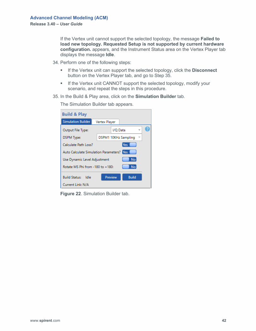
scenario, and repeat the steps in this procedure. 35. In the Build & Play area, click on the Simulation Builder tab.
The Simulation Builder tab appears.
Figure 22. Simulation Builder tab.

Advanced Channel Modeling (ACM) Release 3.40 – User Guide
www.spirent.com 43
36. Click the Preview button. ACM generates plots for the scenario and displays the Plots tab in the View area.
Figure 23. Sample Plots tab.
The Plots tab displays graphs of the following information for each mobile station used in the current scenario: Distance (meters) from base station to mobile station over time Pathloss (dB) from base station to mobile station over time Pathloss (dB) from mobile station to base station over time Theta line of sight (LOS) (degrees) from base station to mobile station over
time Phi LOS (degrees) from base station to mobile station over time Theta DOT (degrees) of mobile station over time Phi DOT (degrees) of mobile station over time Mobile station height (meters) over time Doppler LOS (Hz) of mobile station over time Doppler LOS (Hz) of base station over time Probability of LOS (%) of mobile station over time
Advanced Channel Modeling (ACM) Release 3.40 – User Guide
www.spirent.com 44
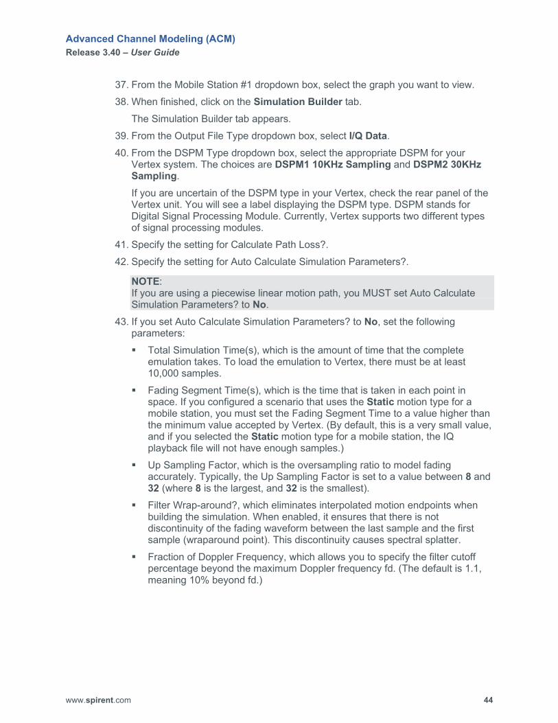
37. From the Mobile Station #1 dropdown box, select the graph you want to view. 38. When finished, click on the Simulation Builder tab.
The Simulation Builder tab appears. 39. From the Output File Type dropdown box, select I/Q Data. 40. From the DSPM Type dropdown box, select the appropriate DSPM for your
Vertex system. The choices are DSPM1 10KHz Sampling and DSPM2 30KHz Sampling. If you are uncertain of the DSPM type in your Vertex, check the rear panel of the Vertex unit. You will see a label displaying the DSPM type. DSPM stands for Digital Signal Processing Module. Currently, Vertex supports two different types of signal processing modules.
41. Specify the setting for Calculate Path Loss?. 42. Specify the setting for Auto Calculate Simulation Parameters?.
NOTE: If you are using a piecewise linear motion path, you MUST set Auto Calculate Simulation Parameters? to No.
43. If you set Auto Calculate Simulation Parameters? to No, set the following parameters: Total Simulation Time(s), which is the amount of time that the complete
emulation takes. To load the emulation to Vertex, there must be at least 10,000 samples.
Fading Segment Time(s), which is the time that is taken in each point in space. If you configured a scenario that uses the Static motion type for a mobile station, you must set the Fading Segment Time to a value higher than the minimum value accepted by Vertex. (By default, this is a very small value, and if you selected the Static motion type for a mobile station, the IQ playback file will not have enough samples.)
Up Sampling Factor, which is the oversampling ratio to model fading accurately. Typically, the Up Sampling Factor is set to a value between 8 and 32 (where 8 is the largest, and 32 is the smallest).
Filter Wrap-around?, which eliminates interpolated motion endpoints when building the simulation. When enabled, it ensures that there is not discontinuity of the fading waveform between the last sample and the first sample (wraparound point). This discontinuity causes spectral splatter.
Fraction of Doppler Frequency, which allows you to specify the filter cutoff percentage beyond the maximum Doppler frequency fd. (The default is 1.1, meaning 10% beyond fd.)

Advanced Channel Modeling (ACM) Release 3.40 – User Guide
www.spirent.com 45
44. Specify the setting for Use Dynamic Level Adjustment. This setting enables you to embed the output level and C/N ratio data in the IQ playback data file when AWGN is enabled for the base station(s) and/or mobile station(s). This feature provides a better digital representation of fading while using Vertex RFM to adjust the overall output level.
45. Click the Build button. The Build Status area on the Simulation Builder tab displays the message Building… and the display area at the bottom of the Simulation Builder tab shows the status of the build process. The amount of time required to build the simulation file depends on the speed and power of the PC running ACM. When the build is complete, several windows displaying various graphs appear, the message Build completed appears at the bottom of the display area on the Simulation Builder tab, and the Build Status area on the Simulation Builder tab displays the message Idle.
NOTE: The length of the IQ playback file is limited to 360 seconds due to system resources. After 360 seconds, the IQ playback file repeats.
46. Close the windows displaying the graphs (if present). 47. Click the Save button on the Scenario ribbon toolbar at the top of the Advanced
Channel Modeling window. 48. In the Views area, click on the Virtual OTA tab.
The Virtual OTA tab appears.
Figure 24. Sample Virtual OTA tab.

Advanced Channel Modeling (ACM) Release 3.40 – User Guide
www.spirent.com 46
49. From the Matrix Size box, select the configuration you are using. Choices are 2x2 and 4x4.
50. Perform one of the following steps: If you want to import the antenna pattern file for the device under test:
a. Click the Import button. The Select Antenna File dialog box appears.
b. Select the file you want to use, and click the Open button. The information from the selected file is displayed in the Virtual OTA coupling matrix.
If you want to manually enter the information into the Virtual OTA coupling matrix, type the information in the appropriate cells in the matrix.
51. In the Build & Play area, click on the Vertex Player tab. The Vertex Player tab appears and displays the file name of the simulation file you built.
52. Set Enable Virtual OTA to Yes. 53. Click the Apply button for Apply VOTA Coupling Matrix.
The Save VOTA IQ Play File dialog box appears.
Figure 25. Sample Save VOTA IQ Play File dialog box.

Advanced Channel Modeling (ACM) Release 3.40 – User Guide
www.spirent.com 47
54. In the File name box, enter a name for the file, and then click the Save button. The display area at the bottom of the Vertex Player tab displays the message Begin applying VOTA matrix and shows the status of the process in which the matrix is applied to the file data. The amount of time required to complete this process depends on the speed and power of the PC running ACM. When the process is complete, the message VOTA matrix applied successfully appears at the bottom of the display area on Vertex Player tab.
55. On the Vertex Player tab, click the Connect button to connect to your Vertex unit. The display area at the bottom of the Vertex Player tab shows the status of the connection process. When the connection is successful, the Instrument Status area on the Vertex Player tab displays the message Connected.
56. On the Vertex Player tab, click the Download button. The File Status area on the Vertex Player tab displays the message Downloading…. When the download is complete, the File Status area displays the message Downloaded, and the display area at the bottom of the Vertex Player tab displays the message Download completed successfully.
57. In the Views area, click on the Network Layout tab. The Network Layout tab appears.
58. On the Vertex Player tab, click the Play button. The Network Layout tab shows the simulation running. The Simulation Status area on the Vertex Player tab displays the message Running….
59. If you want to pause playback, click the Pause button on the Vertex Player tab. To resume playing the file, click the Resume button.
60. When you are finished playing the file, click the Stop button on the Vertex Player tab. The Simulation Status area on the Vertex Player tab displays the message Idle.
61. On the Vertex Player tab, click the Disconnect button. The message Disconnected from Instruments appears in the display area at the bottom of the Vertex Player tab.

Advanced Channel Modeling (ACM) Release 3.40 – User Guide
www.spirent.com 48
Create a Mesh Network Scenario ACM supports the following mesh configurations:
• Full Mesh
• Star
• Loop
• Convoy
• Custom
NOTE: Custom is not selectable. It appears when you create a mesh configuration that is something other than Full Mesh, Star, Loop, or Convoy.
Before creating a mesh network scenario, keep in mind the following information:
• Mesh network scenarios require a license.
• Mesh network scenarios do not contain base stations.
• Mesh network scenarios can support up to 16 mobile stations.
• Every mesh configuration is a subset of a Full Mesh configuration.
• All links between nodes (mobile stations) are bidirectional.
• All nodes use the same carrier frequency (that is, you cannot set a different carrier frequency for each channel).
• In Mesh mode, you must set Use Dynamic Level Adjustment to No on the Simulation Builder tab. ACM only supports digital gains at this time for mesh network scenarios.
To create a mesh network scenario: 1. Click on the Scenario menu at the top of the Advanced Channel Modeling
window. The Scenario ribbon toolbar appears at the top of the window.
Figure 26. Scenario ribbon toolbar.

Advanced Channel Modeling (ACM) Release 3.40 – User Guide
www.spirent.com 49
2. Click the New button to create a new scenario. The New Scenario dialog box appears.
Figure 27. New Scenario dialog box.
3. In the Name box, type the name of the scenario. By default, scenario files are saved to C:\ProgramData\Spirent Communications\Advanced Channel Modeling\Scenarios. If you want to change the location where you want to save the new scenario file, use the Browse button specify the location where you want to save the new scenario file. The folder C:\ProgramData may be hidden in the Windows file system. If you are unable to see the folder C:\ProgramData, perform the following steps: a. Click Windows Start button, type folder options in the associated text box,
and press the ENTER key. The File Explorer Options dialog box appears.
b. Click on the View tab. c. In the Advanced settings list box, click on the Show hidden files, folders,
and drives option button. d. Click the OK button.
4. Click the OK button. The title you entered appears at the top of the ACM window.
NOTE: You MUST save your new scenario file before you can build it.
5. In the Connection Type area on the Scenario ribbon toolbar, click on Mesh. 6. Click the Save button on the Scenario ribbon toolbar.
Advanced Channel Modeling (ACM) Release 3.40 – User Guide
www.spirent.com 50
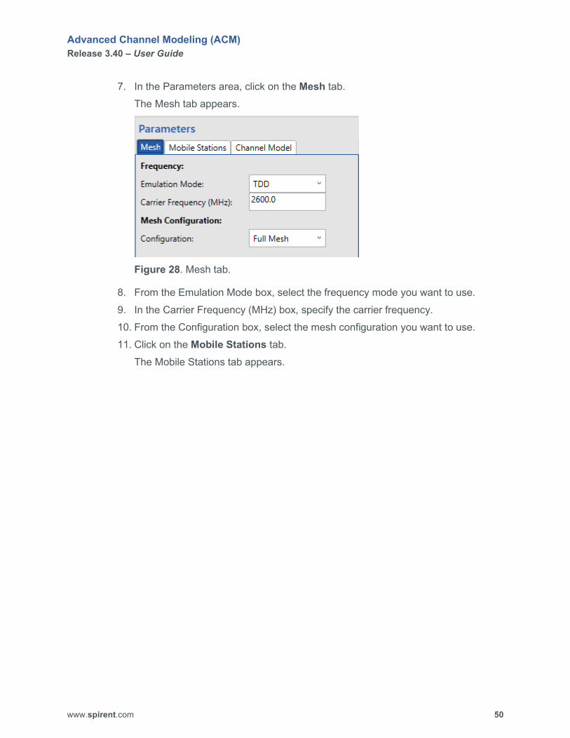
7. In the Parameters area, click on the Mesh tab. The Mesh tab appears.
Figure 28. Mesh tab.
8. From the Emulation Mode box, select the frequency mode you want to use. 9. In the Carrier Frequency (MHz) box, specify the carrier frequency. 10. From the Configuration box, select the mesh configuration you want to use. 11. Click on the Mobile Stations tab.
The Mobile Stations tab appears.

Advanced Channel Modeling (ACM) Release 3.40 – User Guide
www.spirent.com 51
Figure 29. Mobile Stations tab.

Advanced Channel Modeling (ACM) Release 3.40 – User Guide
www.spirent.com 52
12. From the ID dropdown box, select the mobile station you want to use. 13. If you want to customize the name of the mobile station, type the new name in
the Name box. 14. Set Enabled? to Yes.
The Location, Power, and Antenna Parameters become enabled, and the icon for the mobile station appears on the Network Layout tab.
15. Configure the other mobile station parameters. 16. Repeat Steps 12 through 15 for each mobile station you want to use. 17. When you are finished configuring the mobile stations, click on the Channel
Model tab. The Channel Model tab appears.
Figure 30. Channel Model tab.
Advanced Channel Modeling (ACM) Release 3.40 – User Guide
www.spirent.com 53
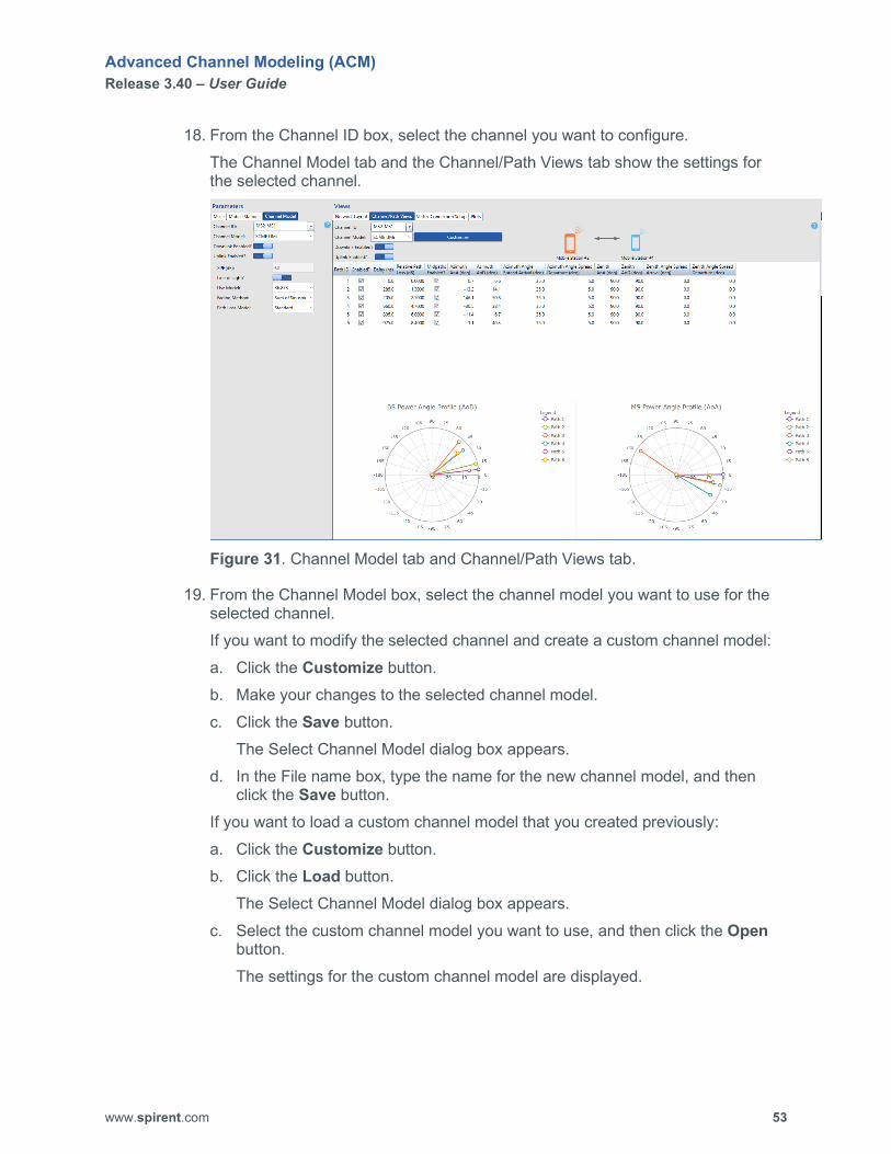
18. From the Channel ID box, select the channel you want to configure. The Channel Model tab and the Channel/Path Views tab show the settings for the selected channel.
Figure 31. Channel Model tab and Channel/Path Views tab.
19. From the Channel Model box, select the channel model you want to use for the selected channel. If you want to modify the selected channel and create a custom channel model: a. Click the Customize button. b. Make your changes to the selected channel model. c. Click the Save button.
The Select Channel Model dialog box appears. d. In the File name box, type the name for the new channel model, and then
click the Save button. If you want to load a custom channel model that you created previously: a. Click the Customize button. b. Click the Load button.
The Select Channel Model dialog box appears. c. Select the custom channel model you want to use, and then click the Open
button. The settings for the custom channel model are displayed.

Advanced Channel Modeling (ACM) Release 3.40 – User Guide
www.spirent.com 54
The illustration at the top of the Channel/Path Views tab shows a bidirectional path between the mobile stations (nodes).
NOTE: The mesh networking scenario supports only bidirectional paths.
20. Configure the other channel model settings. 21. Repeat Steps 18 through 20 for each channel you want to configure. 22. When you are finished configuring the channels, click on the Scenario menu at
the top of the Advanced Channel Modeling window. The Scenario ribbon toolbar appears at the top of the window.
23. Click the Save button. Your changes are saved.
24. In the Views area, click on the Vertex Connection Setup tab. The Vertex Connection Setup tab appears.
Figure 32. Vertex Connection Setup tab.

Advanced Channel Modeling (ACM) Release 3.40 – User Guide
www.spirent.com 55
25. Click the Select New button. The Topology Selector dialog box appears.
Figure 33. Topology Selector tab.
26. Select the appropriate mesh topology for the scenario. 27. Click the Apply button.
The logical diagram and physical diagram of the selected topology are displayed on the Vertex Connection Setup tab.
28. Make sure the PC running ACM can connect to your Vertex unit.

Advanced Channel Modeling (ACM) Release 3.40 – User Guide
www.spirent.com 56
29. In the Build & Play area, click on the Vertex Player tab. The Vertex Player tab appears.
Figure 34. Vertex Player tab.
30. Click the Connect button to connect to your Vertex unit and verify that your system has the required hardware to support the scenario. The display area at the bottom of the Vertex Player tab shows the status of the connection process and whether the selected topology is supported by your Vertex unit. If the Vertex unit can support the selected topology, the message New topology loaded successfully appears, and the Instrument Status area on the Vertex Player tab displays the message Connected as shown in the following figure.
Figure 35. Connected message on the Vertex Player tab.

Advanced Channel Modeling (ACM) Release 3.40 – User Guide
www.spirent.com 57
If the Vertex unit cannot support the selected topology, the message Failed to load new topology. Requested Setup is not supported by current hardware configuration. appears, and the Instrument Status area on the Vertex Player tab displays the message Idle.
31. Perform one of the following steps: If the Vertex unit can support the selected topology, click the Disconnect
button on the Vertex Player tab, and go to Step 32. If the Vertex unit CANNOT support the selected topology, modify your
scenario, and repeat the steps in this procedure. 32. In the Build & Play area, click on the Simulation Builder tab.
The Simulation Builder tab appears.
Figure 36. Simulation Builder tab.
Advanced Channel Modeling (ACM) Release 3.40 – User Guide
www.spirent.com 58
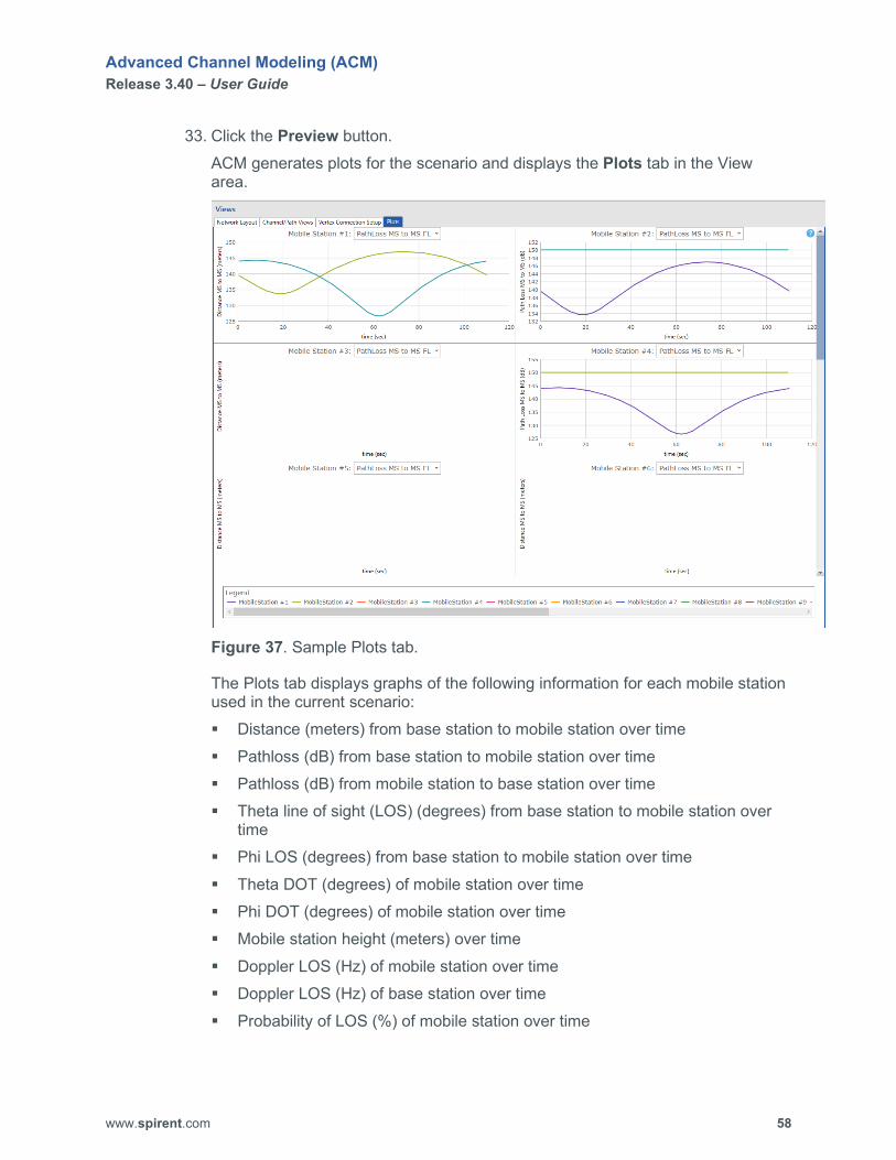
33. Click the Preview button. ACM generates plots for the scenario and displays the Plots tab in the View area.
Figure 37. Sample Plots tab.
The Plots tab displays graphs of the following information for each mobile station used in the current scenario: Distance (meters) from base station to mobile station over time Pathloss (dB) from base station to mobile station over time Pathloss (dB) from mobile station to base station over time Theta line of sight (LOS) (degrees) from base station to mobile station over
time Phi LOS (degrees) from base station to mobile station over time Theta DOT (degrees) of mobile station over time Phi DOT (degrees) of mobile station over time Mobile station height (meters) over time Doppler LOS (Hz) of mobile station over time Doppler LOS (Hz) of base station over time Probability of LOS (%) of mobile station over time
Advanced Channel Modeling (ACM) Release 3.40 – User Guide
www.spirent.com 59
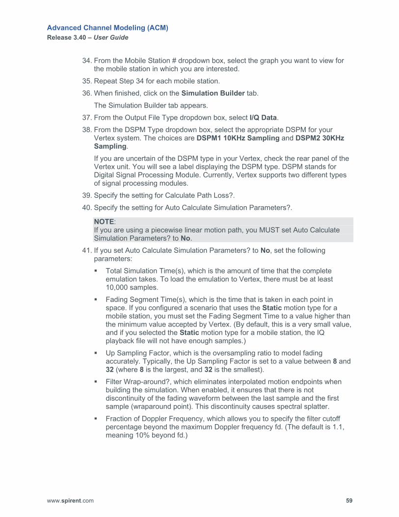
34. From the Mobile Station # dropdown box, select the graph you want to view for the mobile station in which you are interested.
35. Repeat Step 34 for each mobile station. 36. When finished, click on the Simulation Builder tab.
The Simulation Builder tab appears. 37. From the Output File Type dropdown box, select I/Q Data. 38. From the DSPM Type dropdown box, select the appropriate DSPM for your
Vertex system. The choices are DSPM1 10KHz Sampling and DSPM2 30KHz Sampling. If you are uncertain of the DSPM type in your Vertex, check the rear panel of the Vertex unit. You will see a label displaying the DSPM type. DSPM stands for Digital Signal Processing Module. Currently, Vertex supports two different types of signal processing modules.
39. Specify the setting for Calculate Path Loss?. 40. Specify the setting for Auto Calculate Simulation Parameters?.
NOTE: If you are using a piecewise linear motion path, you MUST set Auto Calculate Simulation Parameters? to No.
41. If you set Auto Calculate Simulation Parameters? to No, set the following parameters: Total Simulation Time(s), which is the amount of time that the complete
emulation takes. To load the emulation to Vertex, there must be at least 10,000 samples.
Fading Segment Time(s), which is the time that is taken in each point in space. If you configured a scenario that uses the Static motion type for a mobile station, you must set the Fading Segment Time to a value higher than the minimum value accepted by Vertex. (By default, this is a very small value, and if you selected the Static motion type for a mobile station, the IQ playback file will not have enough samples.)
Up Sampling Factor, which is the oversampling ratio to model fading accurately. Typically, the Up Sampling Factor is set to a value between 8 and 32 (where 8 is the largest, and 32 is the smallest).
Filter Wrap-around?, which eliminates interpolated motion endpoints when building the simulation. When enabled, it ensures that there is not discontinuity of the fading waveform between the last sample and the first sample (wraparound point). This discontinuity causes spectral splatter.
Fraction of Doppler Frequency, which allows you to specify the filter cutoff percentage beyond the maximum Doppler frequency fd. (The default is 1.1, meaning 10% beyond fd.)
Advanced Channel Modeling (ACM) Release 3.40 – User Guide
www.spirent.com 60
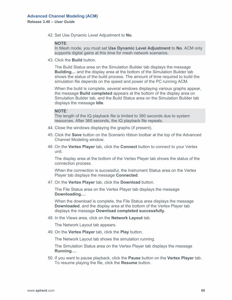
42. Set Use Dynamic Level Adjustment to No.
NOTE: In Mesh mode, you must set Use Dynamic Level Adjustment to No. ACM only supports digital gains at this time for mesh network scenarios.
43. Click the Build button. The Build Status area on the Simulation Builder tab displays the message Building… and the display area at the bottom of the Simulation Builder tab shows the status of the build process. The amount of time required to build the simulation file depends on the speed and power of the PC running ACM. When the build is complete, several windows displaying various graphs appear, the message Build completed appears at the bottom of the display area on Simulation Builder tab, and the Build Status area on the Simulation Builder tab displays the message Idle.
NOTE: The length of the IQ playback file is limited to 360 seconds due to system resources. After 360 seconds, the IQ playback file repeats.
44. Close the windows displaying the graphs (if present). 45. Click the Save button on the Scenario ribbon toolbar at the top of the Advanced
Channel Modeling window. 46. On the Vertex Player tab, click the Connect button to connect to your Vertex
unit. The display area at the bottom of the Vertex Player tab shows the status of the connection process. When the connection is successful, the Instrument Status area on the Vertex Player tab displays the message Connected.
47. On the Vertex Player tab, click the Download button. The File Status area on the Vertex Player tab displays the message Downloading…. When the download is complete, the File Status area displays the message Downloaded, and the display area at the bottom of the Vertex Player tab displays the message Download completed successfully.
48. In the Views area, click on the Network Layout tab. The Network Layout tab appears.
49. On the Vertex Player tab, click the Play button. The Network Layout tab shows the simulation running. The Simulation Status area on the Vertex Player tab displays the message Running….
50. If you want to pause playback, click the Pause button on the Vertex Player tab. To resume playing the file, click the Resume button.

Advanced Channel Modeling (ACM) Release 3.40 – User Guide
www.spirent.com 61
51. When you are finished playing the file, click the Stop button on the Vertex Player tab. The Simulation Status area on the Vertex Player tab displays the message Idle.
52. On the Vertex Player tab, click the Disconnect button. The message Disconnected from Instruments appears in the display area at the bottom of the Vertex Player tab.
Advanced Channel Modeling (ACM) Release 3.40 – User Guide
www.spirent.com 62
Create a MIMO OTA Scenario The MIMO OTA scenario enables you to configure multiple in multiple out (MIMO) over-the-air (OTA) FR2 scenarios. You can use these MIMO OTA FR2 scenarios with a Spirent 5G FR2 UE MIMO OTA test system. In a MIMO OTA network scenario, you specify the following settings:.
• base station,
• channel model, and
• chamber layout (how the probes are located in the chamber). Before creating a MIMO OTA scenario, keep in mind the following information:
• MIMO OTA scenarios require a license.
• MIMO OTA scenarios do not contain mobile stations.
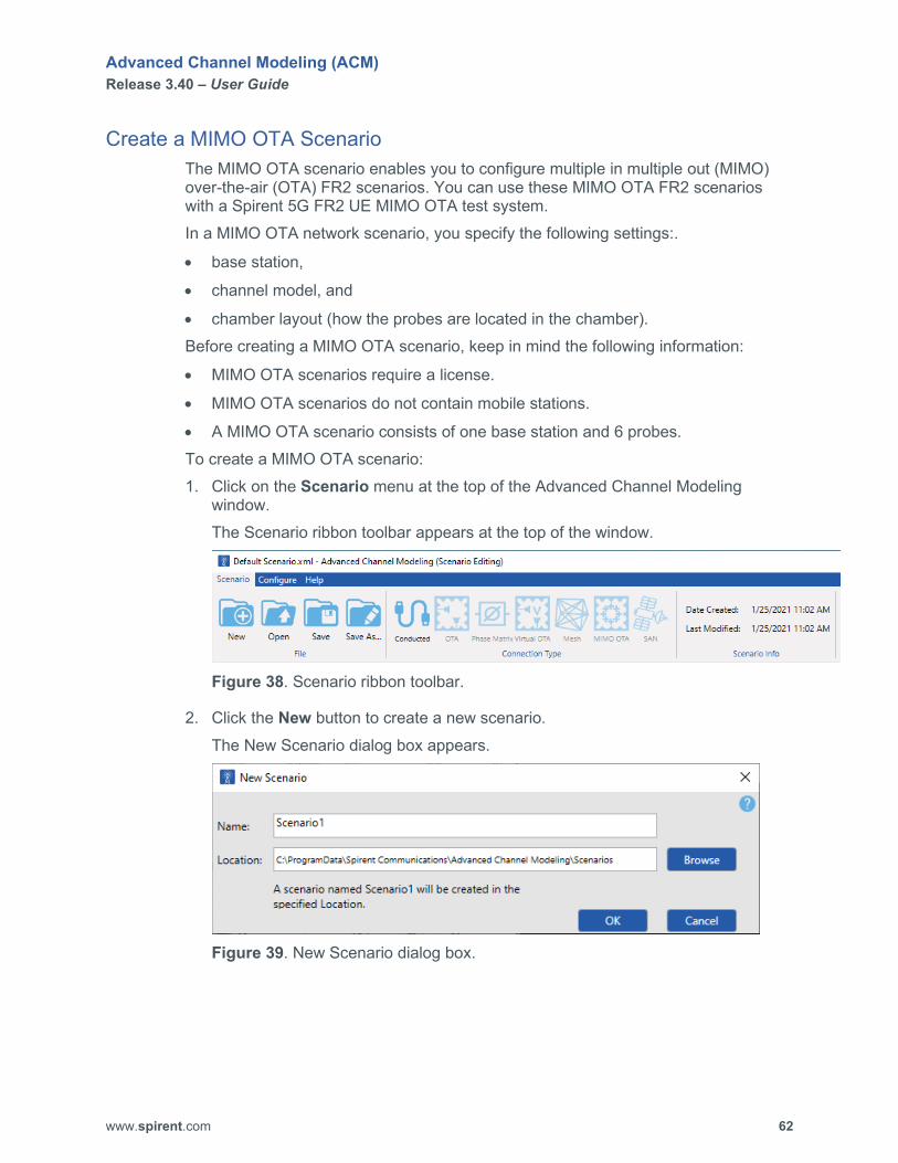
• A MIMO OTA scenario consists of one base station and 6 probes. To create a MIMO OTA scenario: 1. Click on the Scenario menu at the top of the Advanced Channel Modeling
window. The Scenario ribbon toolbar appears at the top of the window.
Figure 38. Scenario ribbon toolbar.
2. Click the New button to create a new scenario. The New Scenario dialog box appears.
Figure 39. New Scenario dialog box.

Advanced Channel Modeling (ACM) Release 3.40 – User Guide
www.spirent.com 63
3. In the Name box, type the name of the scenario. By default, scenario files are saved to C:\ProgramData\Spirent Communications\Advanced Channel Modeling\Scenarios. If you want to change the location where you want to save the new scenario file, use the Browse button specify the location where you want to save the new scenario file. The folder C:\ProgramData may be hidden in the Windows file system. If you are unable to see the folder C:\ProgramData, perform the following steps: a. Click Windows Start button, type folder options in the associated text box,
and press the ENTER key. The File Explorer Options dialog box appears.
b. Click on the View tab. c. In the Advanced settings list box, click on the Show hidden files, folders,
and drives option button. d. Click the OK button.
4. Click the OK button. The title you entered appears at the top of the ACM window.
NOTE: You MUST save your new scenario file before you can build it.
5. In the Connection Type area on the Scenario ribbon toolbar, click on MIMO OTA.
6. Click the Save button on the Scenario ribbon toolbar. 7. In the Parameters area, click on the Base Stations tab.
The Base Stations tab appears.
Advanced Channel Modeling (ACM) Release 3.40 – User Guide
www.spirent.com 64
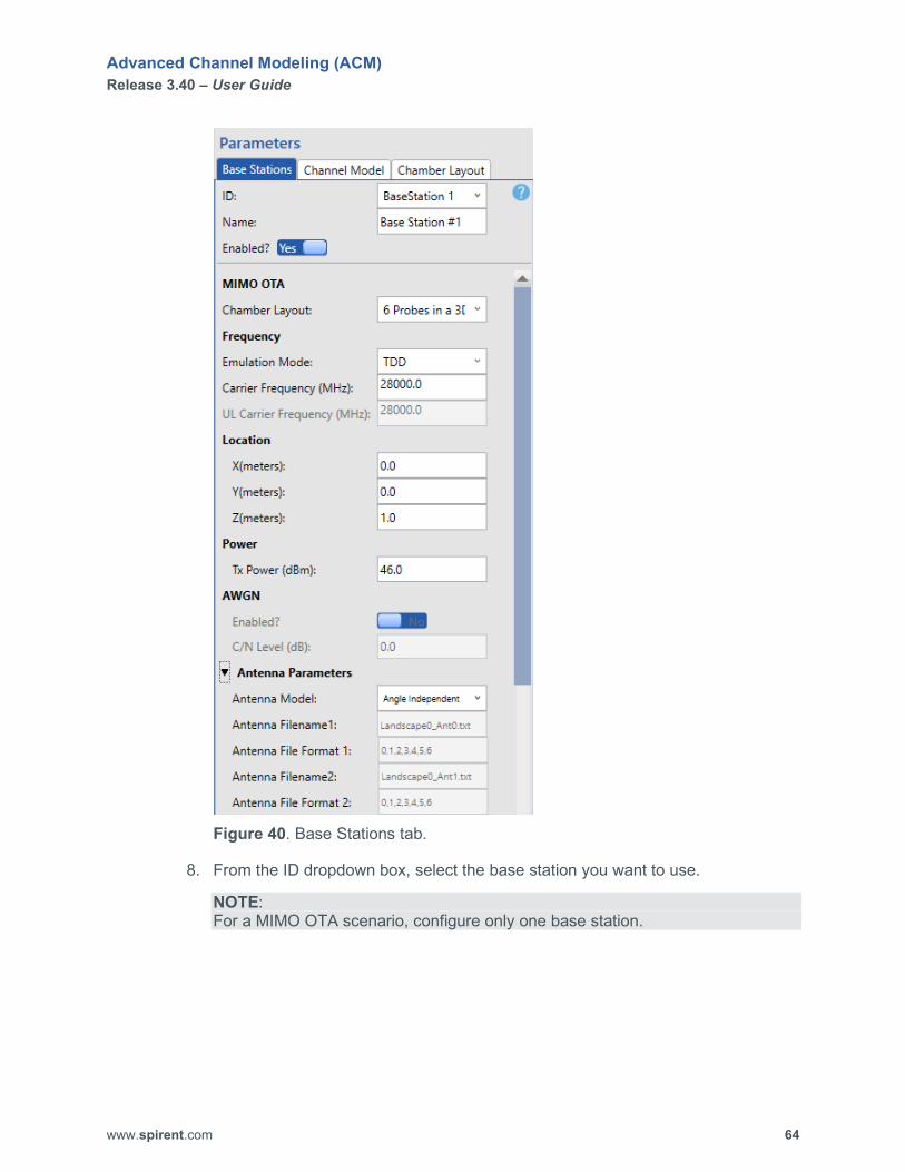
Figure 40. Base Stations tab.
8. From the ID dropdown box, select the base station you want to use.
NOTE: For a MIMO OTA scenario, configure only one base station.

Advanced Channel Modeling (ACM) Release 3.40 – User Guide
www.spirent.com 65
9. If you want to customize the name of the base station, type the new name in the Name box.
10. Set Enabled? to Yes. The Frequency, Location, Power, AWGN, and Antenna Parameters become enabled on the Base Stations tab.
11. Configure the frequency settings. 12. Configure the location settings. 13. Configure the power setting. 14. Configure the AWGN settings. 15. Configure the antenna settings. 16. When you are finished configuring the parameters on the Base Stations tab, click
on the Channel Model tab. The Channel Model tab appears.
Advanced Channel Modeling (ACM) Release 3.40 – User Guide
www.spirent.com 66
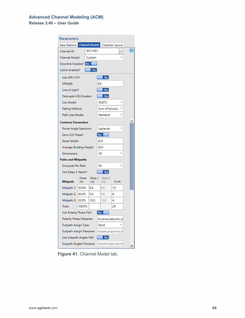
Figure 41. Channel Model tab.
Advanced Channel Modeling (ACM) Release 3.40 – User Guide
www.spirent.com 67
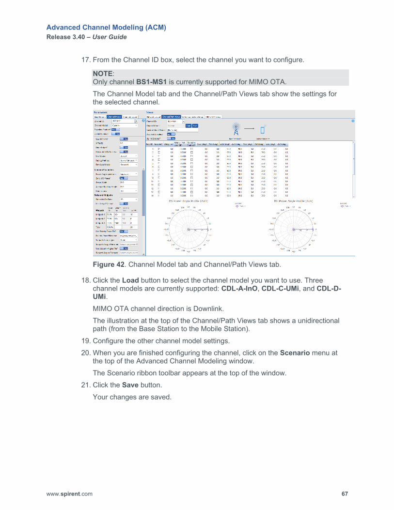
17. From the Channel ID box, select the channel you want to configure.
NOTE: Only channel BS1-MS1 is currently supported for MIMO OTA. The Channel Model tab and the Channel/Path Views tab show the settings for the selected channel.
Figure 42. Channel Model tab and Channel/Path Views tab.
18. Click the Load button to select the channel model you want to use. Three channel models are currently supported: CDL-A-InO, CDL-C-UMi, and CDL-D-UMi. MIMO OTA channel direction is Downlink. The illustration at the top of the Channel/Path Views tab shows a unidirectional path (from the Base Station to the Mobile Station).
19. Configure the other channel model settings. 20. When you are finished configuring the channel, click on the Scenario menu at
the top of the Advanced Channel Modeling window. The Scenario ribbon toolbar appears at the top of the window.
21. Click the Save button. Your changes are saved.
Advanced Channel Modeling (ACM) Release 3.40 – User Guide
www.spirent.com 68
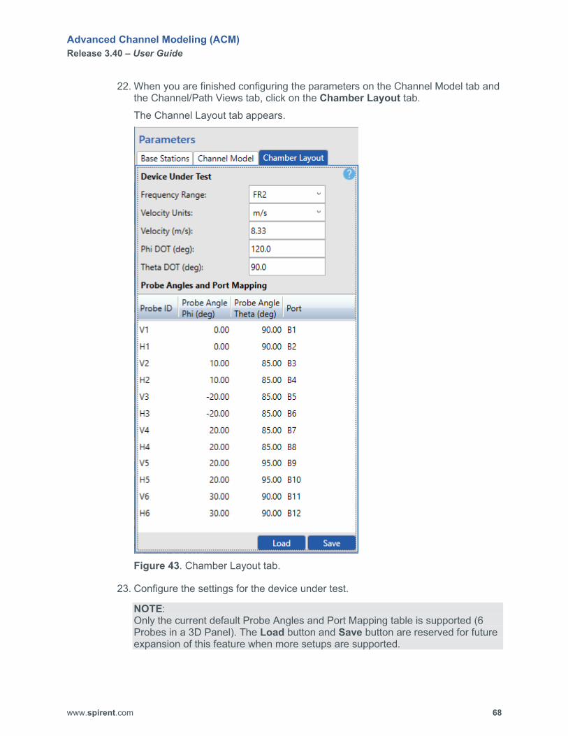
22. When you are finished configuring the parameters on the Channel Model tab and the Channel/Path Views tab, click on the Chamber Layout tab. The Channel Layout tab appears.
Figure 43. Chamber Layout tab.
23. Configure the settings for the device under test.
NOTE: Only the current default Probe Angles and Port Mapping table is supported (6 Probes in a 3D Panel). The Load button and Save button are reserved for future expansion of this feature when more setups are supported.

Advanced Channel Modeling (ACM) Release 3.40 – User Guide
www.spirent.com 69
24. When you are finished configuring the chamber layout, click on the MIMO OTA Setup tab. The MIMO OTA Setup tab appears.
Figure 44. MIMO OTA Setup tab.
25. Configure the settings on the MIMO OTA Setup tab.
NOTE: Mean PSP (%) and Mean PSP at Center of Test Volume (%) are read-only, and the values displayed are the result from building the scenario. Also, the Set Power, Expected Power, and Fractional Power columns are read-only, and the values displayed are the result from building the scenario.
Advanced Channel Modeling (ACM) Release 3.40 – User Guide
www.spirent.com 70
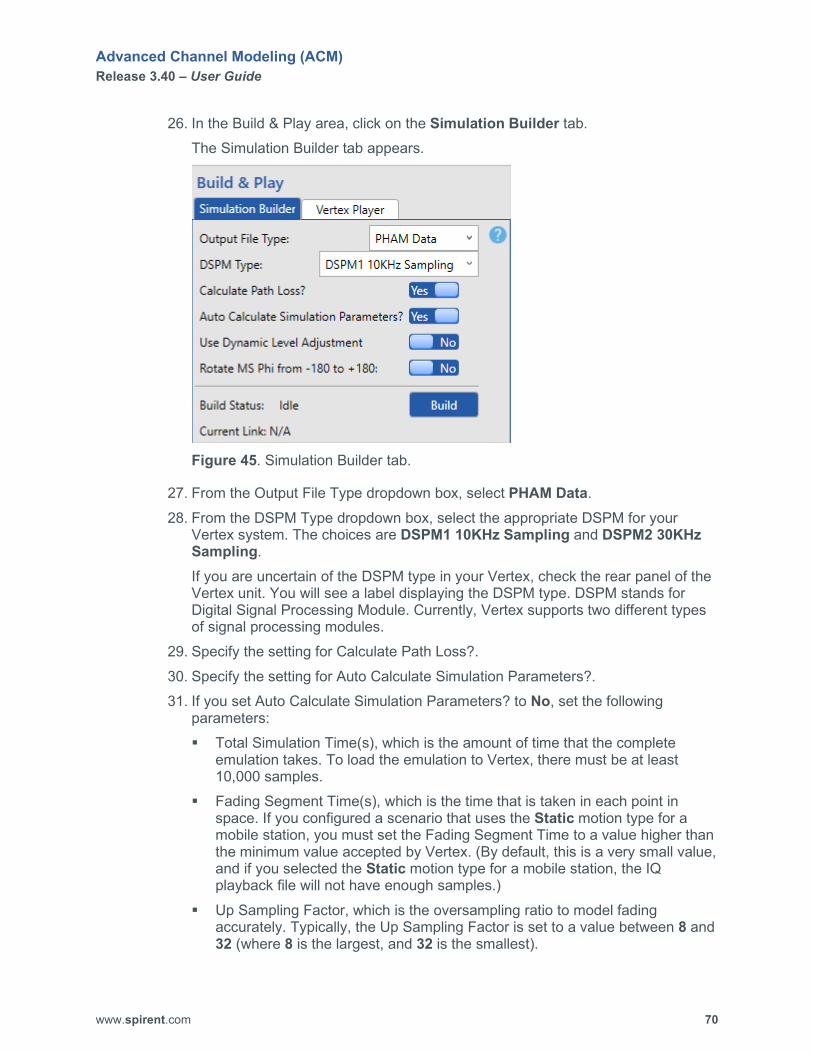
26. In the Build & Play area, click on the Simulation Builder tab. The Simulation Builder tab appears.
Figure 45. Simulation Builder tab.
27. From the Output File Type dropdown box, select PHAM Data. 28. From the DSPM Type dropdown box, select the appropriate DSPM for your
Vertex system. The choices are DSPM1 10KHz Sampling and DSPM2 30KHz Sampling. If you are uncertain of the DSPM type in your Vertex, check the rear panel of the Vertex unit. You will see a label displaying the DSPM type. DSPM stands for Digital Signal Processing Module. Currently, Vertex supports two different types of signal processing modules.
29. Specify the setting for Calculate Path Loss?. 30. Specify the setting for Auto Calculate Simulation Parameters?. 31. If you set Auto Calculate Simulation Parameters? to No, set the following
parameters: Total Simulation Time(s), which is the amount of time that the complete
emulation takes. To load the emulation to Vertex, there must be at least 10,000 samples.
Fading Segment Time(s), which is the time that is taken in each point in space. If you configured a scenario that uses the Static motion type for a mobile station, you must set the Fading Segment Time to a value higher than the minimum value accepted by Vertex. (By default, this is a very small value, and if you selected the Static motion type for a mobile station, the IQ playback file will not have enough samples.)
Up Sampling Factor, which is the oversampling ratio to model fading accurately. Typically, the Up Sampling Factor is set to a value between 8 and 32 (where 8 is the largest, and 32 is the smallest).

Advanced Channel Modeling (ACM) Release 3.40 – User Guide
www.spirent.com 71
Filter Wrap-around?, which eliminates interpolated motion endpoints when building the simulation. When enabled, it ensures that there is not discontinuity of the fading waveform between the last sample and the first sample (wraparound point). This discontinuity causes spectral splatter.
Fraction of Doppler Frequency, which allows you to specify the filter cutoff percentage beyond the maximum Doppler frequency fd. (The default is 1.1, meaning 10% beyond fd.)
32. Make sure Use Dynamic Level Adjustment is set to No. 33. Make sure Rotate MS Phi from -180 to +180 is set to No. 34. Click the Build button.
The Build Status area on the Simulation Builder tab displays the message Building… and the display area at the bottom of the Simulation Builder tab shows the status of the build process. The amount of time required to build the simulation file depends on the speed and power of the PC running ACM. When the build is complete, several windows displaying various graphs appear, the message Build completed appears at the bottom of the display area on Simulation Builder tab, and the Build Status area on the Simulation Builder tab displays the message Idle.
NOTE: The length of the IQ playback file is limited to 360 seconds due to system resources. After 360 seconds, the IQ playback file repeats.
35. Close the windows displaying the graphs. 36. Click the Save button on the Scenario ribbon toolbar at the top of the Advanced
Channel Modeling window. 37. If you want to download the emulation you created to the Vertex unit, perform the
following steps: a. On the Vertex Player tab in the Build & Play area, click the Connect button
to connect to your Vertex unit. The display area at the bottom of the Vertex Player tab shows the status of the connection process. When the connection is successful, the Instrument Status area on the Vertex Player tab displays the message Connected.
b. On the Vertex Player tab, click the Download button. The File Status area on the Vertex Player tab displays the message Downloading…. When the download is complete, the File Status area displays the message Downloaded, and the display area at the bottom of the Vertex Player tab displays the message Download completed successfully.
c. On the Vertex Player tab, click the Disconnect button. The message Disconnected from Instruments appears in the display area at the bottom of the Vertex Player tab.

Advanced Channel Modeling (ACM) Release 3.40 – User Guide
www.spirent.com 72
Create a SAN Scenario The SAN scenario enables you to configure satellite and aeronautical (SAN) scenarios for up to four satellites and four observers. ACM provides the following emulation types:
• Functional test cases (sinusoidal Doppler, linear constant speed, and linear accelerating speed). These test cases try to exaggerate delay and Doppler and are not tied to geometry.
• Geometrical test cases (elliptical, random movement, and geostationary); and
• Field to lab (read measured data from an ASCII file or a GPS motion file). In a SAN scenario, you can specify the following settings:
• scenario type. ACM supports the following SAN scenarios: Sinusoidal, Linear Constant Speed, Linear Accelerating Speed, Elliptical (You specify the orbit/trajectory of the satellite in a 3D coordinate
system.), Random Movement (You create a random movement route in a 3D
coordinate system for a fast moving object like a missile or an airplane.), Geostationary (There is no Doppler shift, but there is large delay.), Field to Lab (You import a movement file that was recorded by a UE.), and GPS (You import the output file from a GPS simulator to create a trajectory).
• distance, maximum range, and minimum loss,
• number of antennas on each satellite (1, 2, or 4),
• emulation mode (TDD or FDD), downlink carrier frequency, uplink carrier frequency, and number of antennas for the observer, and
• channel model. Before creating a SAN scenario, keep in mind the following information:
• SAN scenarios require a license.
• SAN scenarios do not contain base stations or mobile stations.
• Some of the SAN scenarios can support up to 4 satellites and 4 observers.
• If you configure more than one satellite in a scenario, the Network Layout tab displays one satellite only.
• If you configure more than one satellite in a scenario, all of the satellites in the scenario use the same Scenario Settings configured on the SAN tab.
• When you build a SAN scenario, ACM creates a DEE file (.vstb) that can be edited in the DEE Excel template if needed.
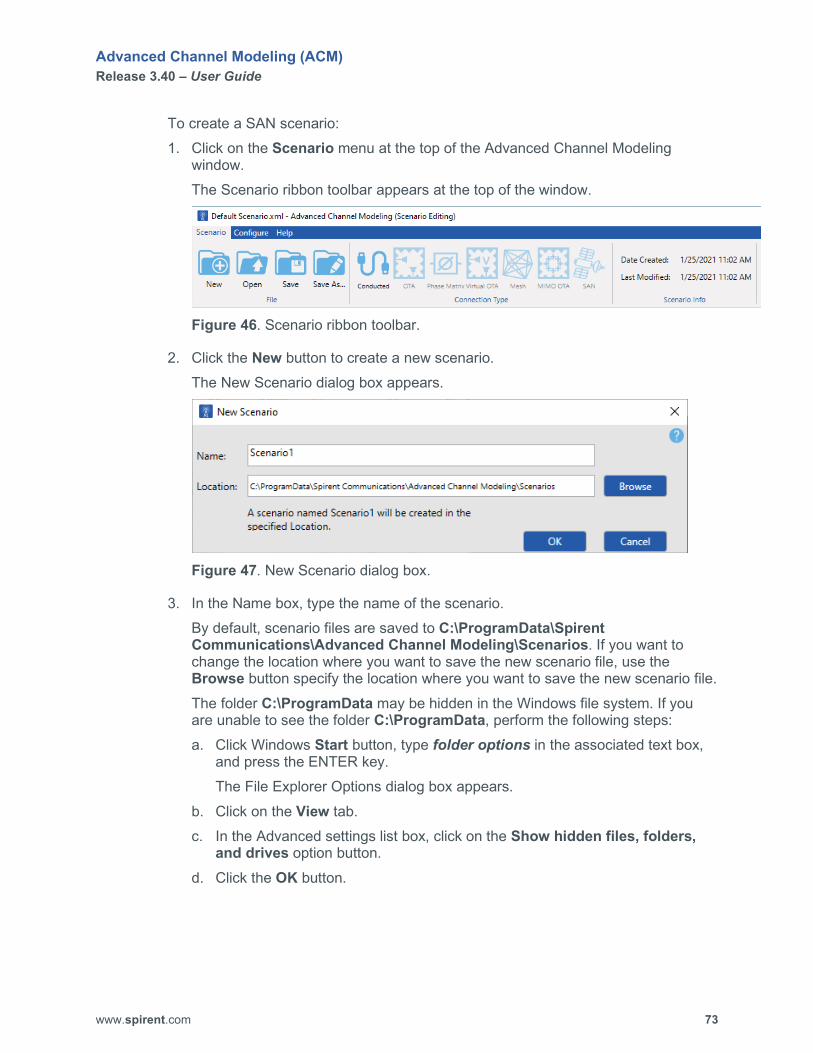
Advanced Channel Modeling (ACM) Release 3.40 – User Guide
www.spirent.com 73
To create a SAN scenario: 1. Click on the Scenario menu at the top of the Advanced Channel Modeling
window. The Scenario ribbon toolbar appears at the top of the window.
Figure 46. Scenario ribbon toolbar.
2. Click the New button to create a new scenario. The New Scenario dialog box appears.
Figure 47. New Scenario dialog box.
3. In the Name box, type the name of the scenario. By default, scenario files are saved to C:\ProgramData\Spirent Communications\Advanced Channel Modeling\Scenarios. If you want to change the location where you want to save the new scenario file, use the Browse button specify the location where you want to save the new scenario file. The folder C:\ProgramData may be hidden in the Windows file system. If you are unable to see the folder C:\ProgramData, perform the following steps: a. Click Windows Start button, type folder options in the associated text box,
and press the ENTER key. The File Explorer Options dialog box appears.
b. Click on the View tab. c. In the Advanced settings list box, click on the Show hidden files, folders,
and drives option button. d. Click the OK button.

Advanced Channel Modeling (ACM) Release 3.40 – User Guide
www.spirent.com 74
4. Click the OK button. The title you entered appears at the top of the ACM window.
NOTE: You MUST save your new scenario file before you can build it.
5. In the Connection Type area on the Scenario ribbon toolbar, click on SAN.
6. Click the Save button on the Scenario ribbon toolbar. 7. In the Parameters area, click on the SAN tab.
The SAN tab appears.
Figure 48. SAN tab.

Advanced Channel Modeling (ACM) Release 3.40 – User Guide
www.spirent.com 75
8. From the Scenario Type dropdown box, select the scenario you want to use. 9. Configure the Scenario Settings. 10. Configure the satellite(s) you want to use. 11. Configure the observer(s) you want to use. 12. When you are finished configuring the parameters on the SAN tab, click on the
Channel Model tab. The Channel Model tab appears.
Figure 49. Channel Model tab.
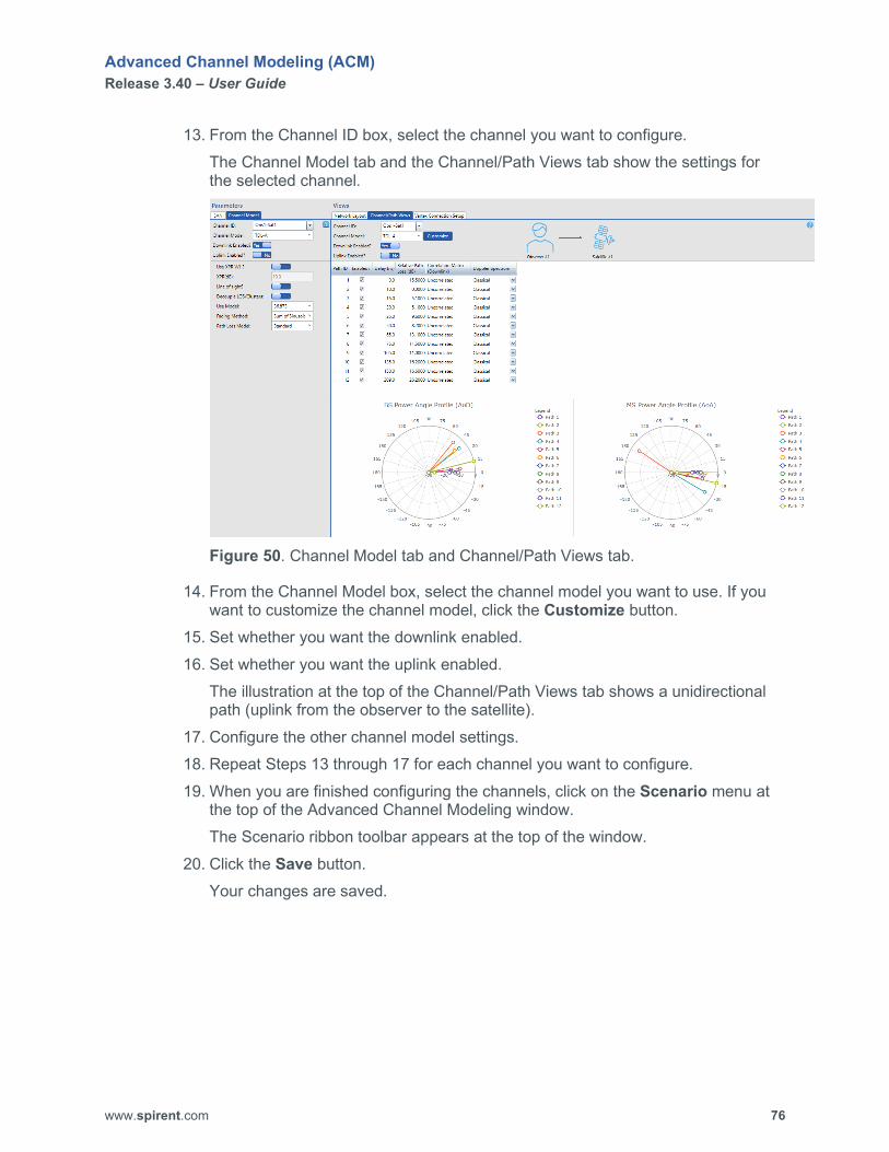
Advanced Channel Modeling (ACM) Release 3.40 – User Guide
www.spirent.com 76
13. From the Channel ID box, select the channel you want to configure. The Channel Model tab and the Channel/Path Views tab show the settings for the selected channel.
Figure 50. Channel Model tab and Channel/Path Views tab.
14. From the Channel Model box, select the channel model you want to use. If you want to customize the channel model, click the Customize button.
15. Set whether you want the downlink enabled. 16. Set whether you want the uplink enabled.
The illustration at the top of the Channel/Path Views tab shows a unidirectional path (uplink from the observer to the satellite).
17. Configure the other channel model settings. 18. Repeat Steps 13 through 17 for each channel you want to configure. 19. When you are finished configuring the channels, click on the Scenario menu at
the top of the Advanced Channel Modeling window. The Scenario ribbon toolbar appears at the top of the window.
20. Click the Save button. Your changes are saved.

Advanced Channel Modeling (ACM) Release 3.40 – User Guide
www.spirent.com 77
21. In the Build & Play area, click on the Simulation Builder tab. The Simulation Builder tab appears.
Figure 51. Simulation Builder tab.
22. From the Output File Type dropdown box, select DEE Data. 23. From the DSPM Type dropdown box, select the appropriate DSPM for your
Vertex system. The choices are DSPM1 10KHz Sampling and DSPM2 30KHz Sampling. If you are uncertain of the DSPM type in your Vertex, check the rear panel of the Vertex unit. You will see a label displaying the DSPM type. DSPM stands for Digital Signal Processing Module. Currently, Vertex supports two different types of signal processing modules.
24. Click the Build button. The Build Status area on the Simulation Builder tab displays the message Building… and the display area at the bottom of the Simulation Builder tab shows the status of the build process. The amount of time required to build the simulation file depends on the speed and power of the PC running ACM. When the build is complete, several windows displaying various graphs appear, the message Build completed appears at the bottom of the display area on the Simulation Builder tab, and the Build Status area on the Simulation Builder tab displays the message Idle.
25. Close the windows displaying the graphs. 26. Click the Save button on the Scenario ribbon toolbar at the top of the Advanced
Channel Modeling window.
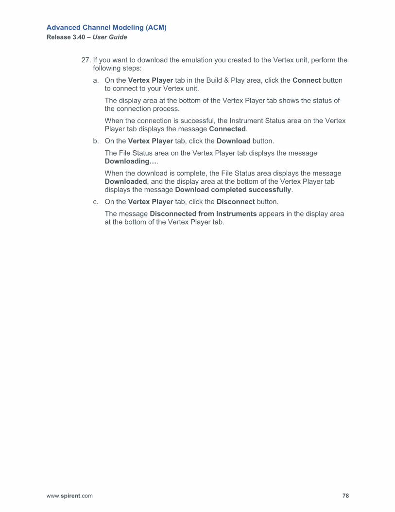
Advanced Channel Modeling (ACM) Release 3.40 – User Guide
www.spirent.com 78
27. If you want to download the emulation you created to the Vertex unit, perform the following steps: a. On the Vertex Player tab in the Build & Play area, click the Connect button
to connect to your Vertex unit. The display area at the bottom of the Vertex Player tab shows the status of the connection process. When the connection is successful, the Instrument Status area on the Vertex Player tab displays the message Connected.
b. On the Vertex Player tab, click the Download button. The File Status area on the Vertex Player tab displays the message Downloading…. When the download is complete, the File Status area displays the message Downloaded, and the display area at the bottom of the Vertex Player tab displays the message Download completed successfully.
c. On the Vertex Player tab, click the Disconnect button. The message Disconnected from Instruments appears in the display area at the bottom of the Vertex Player tab.
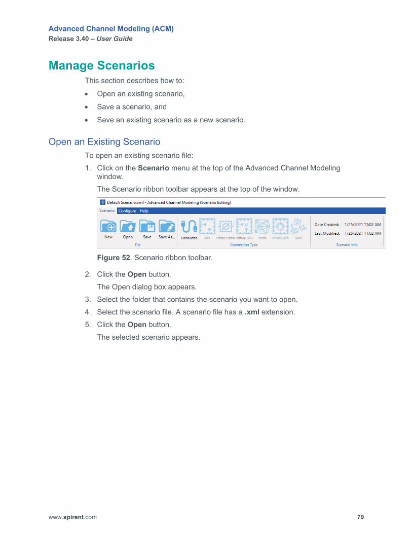
Advanced Channel Modeling (ACM) Release 3.40 – User Guide
www.spirent.com 79
Manage Scenarios This section describes how to:
• Open an existing scenario,
• Save a scenario, and
• Save an existing scenario as a new scenario.
Open an Existing Scenario To open an existing scenario file: 1. Click on the Scenario menu at the top of the Advanced Channel Modeling
window. The Scenario ribbon toolbar appears at the top of the window.
Figure 52. Scenario ribbon toolbar.
2. Click the Open button. The Open dialog box appears.
3. Select the folder that contains the scenario you want to open. 4. Select the scenario file. A scenario file has a .xml extension. 5. Click the Open button.
The selected scenario appears.

Advanced Channel Modeling (ACM) Release 3.40 – User Guide
www.spirent.com 80
Save a Scenario To save changes for a scenario: 1. Click on the Scenario menu at the top of the Advanced Channel Modeling
window. The Scenario ribbon toolbar appears at the top of the window.
Figure 53. Scenario ribbon toolbar.
2. Click the Save button. Your changes are saved.
Save an Existing Scenario as a New Scenario To save an existing scenario as a new scenario: 1. Open the scenario you want to save as a new scenario. See “Open an Existing
Scenario” on page 79. 2. Click on the Scenario menu at the top of the Advanced Channel Modeling
window. The Scenario ribbon toolbar appears at the top of the window.
Figure 54. Scenario ribbon toolbar.
3. Click the Save As button. The Save Scenario As dialog box appears.
4. In the Name box, type the name of the scenario. By default, scenario files are saved to C:\ProgramData\Spirent Communications\Advanced Channel Modeling\Scenarios. If you want to change the location where you want to save the new scenario file, use the Browse button specify the location where you want to save the new scenario file.
5. Click the OK button. The title you entered appears at the top of the ACM window.

Advanced Channel Modeling (ACM) Release 3.40 – User Guide
www.spirent.com 81
Manage Base Stations This section describes how to:
• Add (enable) a base station
• Modify a base station
• Delete (disable) a base station
Add a Base Station When working with base stations, keep in mind the following information: You can have a maximum of 16 base stations. You must have at least 1 base station enabled except in mesh network
scenarios. Base stations are not used in mesh network scenarios.
The base station settings include:
• frequency emulation mode (FDD or TDD)
• carrier frequency
• location of each base station and the height of the transmitter on each base station. (The height of the transmitter is the height above the ground.)
• antenna parameters such as theta tilt, theta down tilt, antenna pattern, and # of rows and # of columns (which defines the configuration of the antenna array)
To add (enable) a base station: 1. In the Parameters area, click on the Base Stations tab.
The Base Stations tab appears.

Advanced Channel Modeling (ACM) Release 3.40 – User Guide
www.spirent.com 82
Figure 55. Base Stations tab.

Advanced Channel Modeling (ACM) Release 3.40 – User Guide
www.spirent.com 83
2. From the ID dropdown box, select the base station you want to add. 3. If you want to customize the name of the base station, type the new name in the
Name box. 4. Set Enabled? to Yes.
The Frequency, Location, Power, and Antenna Parameters become enabled, and the icon for the base station appears on the Network Layout tab.
5. Configure the base station parameters.
Modify a Base Station To modify a base station: 1. In the Parameters area, click on the Base Stations tab.
The Base Stations tab appears. 2. From the ID dropdown box, select the base station you want to modify.
The settings for the selected base station are displayed. 3. Make your changes.
Delete a Base Station To delete (disable) a base station: 1. In the Parameters area, click on the Base Stations tab.
The Base Stations tab appears. 2. From the ID dropdown box, select the base station you want to delete (disable). 3. Set Enabled? to No.
The Frequency, Location, Power, and Antenna Parameters become disabled, and the icon for the base station is removed from the Network Layout tab.

Advanced Channel Modeling (ACM) Release 3.40 – User Guide
www.spirent.com 84
Using Antenna Settings from a Text File ACM allows you to read the settings for an antenna from a text file. The information in the text file must be in the following format:
• Column 0 – frequency (if available)
• Column 1 – elevation (in degrees)
• Column 2 – azimuth (in degrees)
• Column 3 – vertical gain (in dB)
• Column 4 – horizontal gain (in dB)
• Column 5 – vertical phase (in degrees)
• Column 6 – horizontal phase (in degrees) If the information in your text file is not in this order, you can use the Antenna File Format box in ACM to specify the correct order in your text file. For example, suppose your text file has the information arranged in the following order:
• Column 0 – frequency
• Column 1 – azimuth (in degrees)
• Column 2 – horizontal gain (in dB)
• Column 3 – vertical gain (in dB)
• Column 4 – elevation (in degrees)
• Column 5 – horizontal phase (in degrees)
• Column 6 – vertical phase (in degrees) To arrange the data in the proper order for ACM, you would set the order in the corresponding Antenna File Format box to 0,4,1,3,2,6,5.
NOTE: If you want to use Vertex antenna files, you must convert radians to degrees. ACM requires degrees.

Advanced Channel Modeling (ACM) Release 3.40 – User Guide
www.spirent.com 85
Manage Mobile Stations This section describes how to:
• Add (enable) a mobile station
• Modify a mobile station
• Delete (disable) a mobile station
Add a Mobile Station You can have a maximum of 16 mobile stations. You must have at least 1 mobile station enabled. The mobile station settings include:
• Motion type for the mobile station (static, linear motion, circular motion, or piecewise linear motion)
• Starting point and ending point for the mobile station (if using linear or circular motion)
• Velocity of the mobile station (if using linear or circular motion)
• Rotation of the mobile station (if using circular motion). A mobile station can rotate either clockwise or counter clockwise.
• Antenna parameters such as theta tilt, antenna pattern, and the number of rows and the number of columns (which defines the configuration of the antenna array)
To add (enable) a mobile station: 1. In the Parameters area, click on the Mobile Stations tab.
The Mobile Stations tab appears.
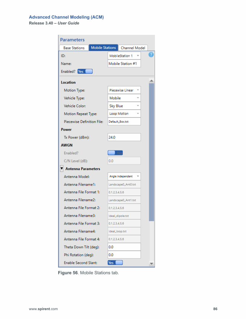
Advanced Channel Modeling (ACM) Release 3.40 – User Guide
www.spirent.com 86
Figure 56. Mobile Stations tab.
Advanced Channel Modeling (ACM) Release 3.40 – User Guide
www.spirent.com 87
2. From the ID dropdown box, select the mobile station you want to add. 3. If you want to customize the name of the mobile station, type the new name in
the Name box. 4. Set Enabled? to Yes.
The Location, Power, and Antenna Parameters become enabled, and the icon for the mobile station appears on the Network Layout tab.
5. Configure the mobile station parameters.
Modify a Mobile Station To modify a mobile station: 1. In the Parameters area, click on the Mobile Stations tab.
The Mobile Stations tab appears. 2. From the ID dropdown box, select the mobile station you want to modify.
The settings for the selected mobile station are displayed. 3. Make your changes.
Delete a Mobile Station To delete (disable) a mobile station: 1. In the Parameters area, click on the Mobile Stations tab.
The Mobile Stations tab appears. 2. From the ID dropdown box, select the mobile station you want to delete (disable). 3. Set Enabled? to No.
The Location, Power, and Antenna Parameters become disabled, and the icon for the mobile station is removed from the Network Layout tab.

Advanced Channel Modeling (ACM) Release 3.40 – User Guide
www.spirent.com 88
Configure Channels By default, a scenario is unidirectional. If you want a bidirectional scenario, set Uplink Enabled? to Yes on the Channel Model tab for the selected channel.
NOTE: All mesh network scenarios are bidirectional.
To configure a channel: 1. In the Parameters area, click on the Channel Model tab.
The Channel Model tab appears.
Figure 57. Channel Model tab.
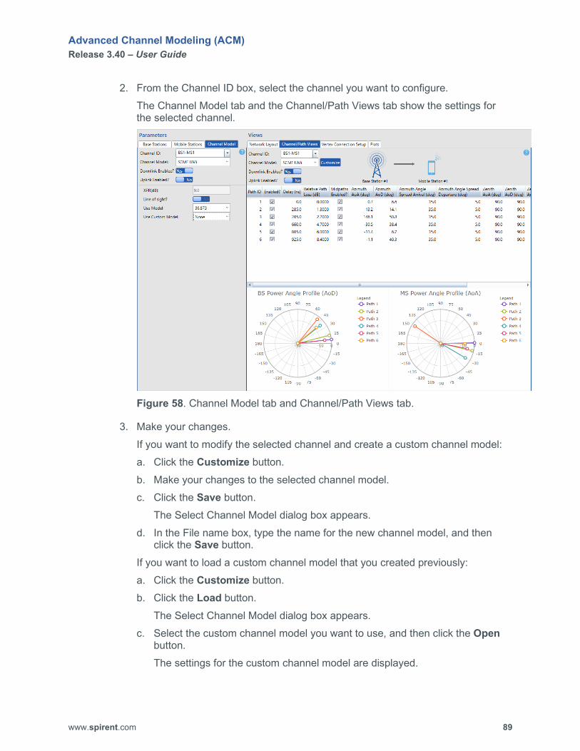
Advanced Channel Modeling (ACM) Release 3.40 – User Guide
www.spirent.com 89
2. From the Channel ID box, select the channel you want to configure. The Channel Model tab and the Channel/Path Views tab show the settings for the selected channel.
Figure 58. Channel Model tab and Channel/Path Views tab.
3. Make your changes. If you want to modify the selected channel and create a custom channel model: a. Click the Customize button. b. Make your changes to the selected channel model. c. Click the Save button.
The Select Channel Model dialog box appears. d. In the File name box, type the name for the new channel model, and then
click the Save button. If you want to load a custom channel model that you created previously: a. Click the Customize button. b. Click the Load button.
The Select Channel Model dialog box appears. c. Select the custom channel model you want to use, and then click the Open
button. The settings for the custom channel model are displayed.
Advanced Channel Modeling (ACM) Release 3.40 – User Guide
www.spirent.com 90
If you select a TDL channel model, the Channel/Path Views tab displays the following settings: path ID whether the path is enabled delay (ns) relative path loss (dB) downlink correlation matrix uplink correlation matrix Doppler spectrum For a TDL channel model, you can load an existing correlation matrix or configure the correlation matrix to one of the following settings using the Correlation Matrix Editor dialog box: Uncorrelated Calculated LTE Low Correlation LTE Medium Correlation LTE High Correlation Custom The Correlation Matrix Editor dialog box appears when you click on a cell in the Correlation Matrix column (Downlink or Uplink). For a TDL channel model, you can also configure the Doppler Spectrum to one of the following settings: Classical
The shape of the Classical Doppler spectrum is given by the following equation: S(f) = 1/sqrt(fm^2-f^2) For -fm<f<fm, and 0 otherwise, where fm is the maximum Doppler shift.
Laplacian The shape of the Laplacian Doppler spectrum is given by the following equation: S(f) = real(1/(sqrt(2)*sigma)*(exp(-sqrt(2)*abs(acos(f/fm)-mu)/sigma)+exp(-sqrt(2)*abs(-acos(f/fm)-mu)/sigma))/sqrt(fm^2-f^2)) For -fm<f<fm, and 0 otherwise, where fm is the maximum Doppler shift, sigma is the angle spread of the Laplacian cluster, and mu is the mean angle of arrival of the cluster.

Advanced Channel Modeling (ACM) Release 3.40 – User Guide
www.spirent.com 91
Bell The shape of the Bell Doppler spectrum is given by the following equation: S(f) = 1/(1+A*(fmax/f)^2) with A=9, and fmax is 5*fm, and fm is the maximum Doppler shift.
Half-Bathtub Left The shape of the Half-Bathtub Left Doppler spectrum is given by the following equation: S(f) = 1/sqrt(fm^2-f^2) For -fm<f<0, and 0 otherwise, where fm is the maximum Doppler shift.
Half-Bathtub Right The shape of the Half-Bathtub Right Doppler spectrum is given by the following equation: S(f) = 1/sqrt(fm^2-f^2) For 0<f<fm, and 0 otherwise, where fm is the maximum Doppler shift.
Round Top The shape of the Round Top Doppler spectrum is given by the following equation: S(f) = 1-1.720(f/fm)^2+0.785(f/fm)^4 For f<fm, 0 otherwise, where fm is the maximum Doppler shift. The following figure shows what the shape looks like.

Advanced Channel Modeling (ACM) Release 3.40 – User Guide
www.spirent.com 92
Figure 59. Shape of the Round Top Doppler spectrum.
The Doppler shape is used for the Stanford University Interim (SUI) channel models. The typical use of SUI channel models is in fixed wireless access.
4. If you want this channel to be bidirectional, set Uplink Enabled? to Yes. 5. If you customized the channel model and want to save your changes, click the
Save button. 6. Repeat Steps 2 through 5 for each channel you want to configure.

Advanced Channel Modeling (ACM) Release 3.40 – User Guide
www.spirent.com 93
Settings to Create the Same Fading Sequence from Run to Run
The following settings on the Channel Model tab are necessary for you to obtain the same fading sequence from run to run:
• Use Polarity Phase File? (Yes)
• Polarity Phase Filename
• Subpath Assign Type
• Use Midpath Map File? (Yes)
• Midpath Map Filename
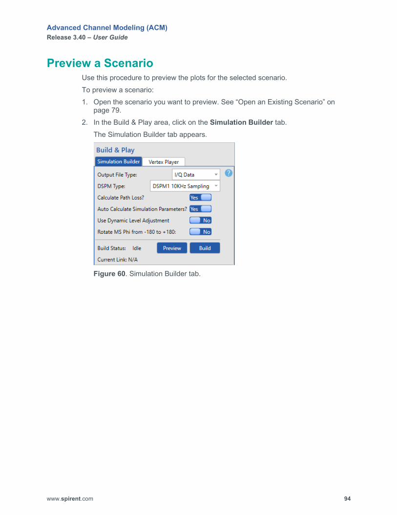
Advanced Channel Modeling (ACM) Release 3.40 – User Guide
www.spirent.com 94
Preview a Scenario Use this procedure to preview the plots for the selected scenario. To preview a scenario: 1. Open the scenario you want to preview. See “Open an Existing Scenario” on
page 79. 2. In the Build & Play area, click on the Simulation Builder tab.
The Simulation Builder tab appears.
Figure 60. Simulation Builder tab.

Advanced Channel Modeling (ACM) Release 3.40 – User Guide
www.spirent.com 95
3. Click the Preview button. ACM generates plots for the scenario and displays the Plots tab in the View area.
Figure 61. Sample Plots tab.
The Plots tab displays graphs of the following information for each mobile station used in the current scenario: Distance (meters) from base station to mobile station over time Pathloss (dB) from base station to mobile station over time Pathloss (dB) from mobile station to base station over time Theta line of sight (LOS) (degrees) from base station to mobile station over
time Phi LOS (degrees) from base station to mobile station over time Theta DOT (degrees) of mobile station over time Phi DOT (degrees) of mobile station over time Mobile station height (meters) over time Doppler LOS (Hz) of mobile station over time Doppler LOS (Hz) of base station over time Probability of LOS (%) of mobile station over time
4. From the Mobile Station #1 dropdown box, select the graph you want to view. 5. Repeat Step 4 for each mobile station.
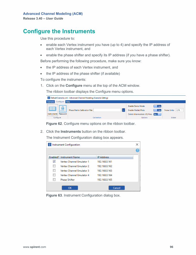
Advanced Channel Modeling (ACM) Release 3.40 – User Guide
www.spirent.com 96
Configure the Instruments Use this procedure to:
• enable each Vertex instrument you have (up to 4) and specify the IP address of each Vertex instrument, and
• enable the phase shifter and specify its IP address (if you have a phase shifter). Before performing the following procedure, make sure you know:
• the IP address of each Vertex instrument, and
• the IP address of the phase shifter (if available) To configure the instruments: 1. Click on the Configure menu at the top of the ACM window.
The ribbon toolbar displays the Configure menu options.
Figure 62. Configure menu options on the ribbon toolbar.
2. Click the Instruments button on the ribbon toolbar. The Instrument Configuration dialog box appears.
Figure 63. Instrument Configuration dialog box.

Advanced Channel Modeling (ACM) Release 3.40 – User Guide
www.spirent.com 97
3. Select (check) the Enabled? check box for Vertex Channel Emulator 1. 4. If the IP address displayed for Vertex Channel Emulator 1 does not match the IP
address of your primary Vertex instrument, click on the IP address, type the correct IP address for that instrument, and press the ENTER key.
5. If you have a second Vertex unit, perform the following steps: a. Select (check) the Enabled? check box for Vertex Channel Emulator 2. b. If the IP address displayed for Vertex Channel Emulator 2 does not match the
IP address of your second Vertex instrument, click on the IP address, type the correct IP address for that instrument, and press the ENTER key.
6. If you have a third Vertex unit, perform the following steps: a. Select (check) the Enabled? check box for Vertex Channel Emulator 3. b. If the IP address displayed for Vertex Channel Emulator 3 does not match the
IP address of your third Vertex instrument, click on the IP address, type the correct IP address for that instrument, and press the ENTER key.
7. If you have a fourth Vertex unit, perform the following steps: a. Select (check) the Enabled? check box for Vertex Channel Emulator 4. b. If the IP address displayed for Vertex Channel Emulator 4 does not match the
IP address of your fourth Vertex instrument, click on the IP address, type the correct IP address for that instrument, and press the ENTER key.
8. If you have a phase shifter, perform the following steps: a. Select (check) the Enabled? check box for Phase Shifter. b. If the IP address displayed for Phase Shifter does not match the IP address
of your phase shifter, click on the IP address, type the correct IP address for that instrument, and press the ENTER key.
9. Click the OK button.

Advanced Channel Modeling (ACM) Release 3.40 – User Guide
www.spirent.com 98
Build and Play a Scenario When you build a scenario, ACM generates one or more output files that are stored in the folder for that scenario. You can build two types of output files:
• I/Q Data
• PHAM Data If you build an I/Q Data output file, ACM creates an I/Q playback data file in text format. You can download the I/Q playback file to Vertex via the ACM Vertex Player. (You can also download this file manually using the Vertex GUI.) If you build a PHAM Data output file, ACM creates a text file that stores a list of Vertex RPI commands. ACM can read these commands and download the commands to Vertex via the ACM Vertex Player. To build and play a scenario: 1. Open the scenario you want to build and play. See “Open an Existing Scenario”
on page 79. 2. In the Views area, click on the Channel/Path Views tab.
The Channel/Path Views tab appears.

Advanced Channel Modeling (ACM) Release 3.40 – User Guide
www.spirent.com 99
Figure 64. Channel/Path Views tab.
3. In the Channel ID dropdown box, select the first channel. 4. Verify the settings for each path and the polar plots for the mobile station and the
base station. 5. Repeat Steps 3 and 4 for each channel. 6. Verify the IP addresses of the Vertex unit(s). See “Configure the Instruments” on
page 96.

Advanced Channel Modeling (ACM) Release 3.40 – User Guide
www.spirent.com 100
7. In the Views area, click on the Vertex Connection Setup tab. The Vertex Connection Setup tab appears.
Figure 65. Vertex Connection Setup tab.

Advanced Channel Modeling (ACM) Release 3.40 – User Guide
www.spirent.com 101
8. Click the Select New button. The Topology Selector dialog box appears.
Figure 66. Topology Selector tab.
9. Select the appropriate topology for the scenario, and then click the Apply button. The logical diagram and physical diagram of the selected topology are displayed on the Vertex Connection Setup tab.
Figure 67. Sample topology.

Advanced Channel Modeling (ACM) Release 3.40 – User Guide
www.spirent.com 102
NOTE: In ACM, there is no difference between an 8x4 BiDirectional (TDD) topology and an 8x2 Multi-User (2 Users, DL) BiDirectional (TDD) topology. The geometry sets the correlation between the users, so you do not have to distinguish the multi-user case from the normal case.
10. Make sure the PC running ACM can connect to your Vertex unit. 11. In the Build & Play area, click on the Vertex Player tab.
The Vertex Player tab appears.
Figure 68. Vertex Player tab.
12. Click the Connect button to connect to your Vertex unit and verify that your system has the required hardware to support the scenario. The display area at the bottom of the Vertex Player tab shows the status of the connection process and whether the selected topology is supported by your Vertex unit. If the Vertex unit can support the selected topology, the message New topology loaded successfully appears, and the Instrument Status area on the Vertex Player tab displays the message Connected as shown in the following figure.

Advanced Channel Modeling (ACM) Release 3.40 – User Guide
www.spirent.com 103
Figure 69. Connected message on the Vertex Player tab.
If the Vertex unit cannot support the selected topology, the message Failed to load new topology. Requested Setup is not supported by current hardware configuration. appears, and the Instrument Status area on the Vertex Player tab displays the message Idle.
13. Perform one of the following steps: If the Vertex unit can support the selected topology, click the Disconnect
button on the Vertex Player tab, and go to Step 14. If the Vertex unit CANNOT support the selected topology, modify your
scenario, and repeat Steps 2 through 12. 14. Preview the scenario. See “Preview a Scenario” on page 94. 15. In the Build & Play area, click on the Simulation Builder tab.
The Simulation Builder tab appears.
Figure 70. Simulation Builder tab.
Advanced Channel Modeling (ACM) Release 3.40 – User Guide
www.spirent.com 104
16. From the Output File Type dropdown box, select the type of output file you want to create. The choices are I/Q Data and PHAM Data.
17. From the DSPM Type dropdown box, select the appropriate DSPM for your Vertex system. The choices are DSPM1 10KHz Sampling and DSPM2 30KHz Sampling. If you are uncertain of the DSPM type in your Vertex, check the rear panel of the Vertex unit. You will see a label displaying the DSPM type. “DSPM” stands for Digital Signal Processing Module. Currently, Vertex supports two different types of signal processing modules.
18. Specify the setting for Calculate Path Loss?. 19. Specify the setting for Auto Calculate Simulation Parameters?.
NOTE: If you are using a piecewise linear motion path, you MUST set Auto Calculate Simulation Parameters? to No.
20. If you set Auto Calculate Simulation Parameters? to No, set the following parameters: Total Simulation Time (s), which is the amount of time that the complete
emulation takes. To load the emulation to Vertex, there must be at least 10,000 samples.
Fading Segment Time (s), which is the time that is taken in each point in space. If you configured a scenario that uses the Static motion type for a mobile station, you must set the Fading Segment Time to a value higher than the minimum value accepted by Vertex. (By default, this is a very small value, and if you selected the Static motion type for a mobile station, the IQ playback file will not have enough samples.)
Up Sampling Factor, which is the oversampling ratio to model fading accurately. Typically, the Up Sampling Factor is set to a value between 8 and 32 (where 8 is the largest, and 32 is the smallest).
Filter Wrap-around?, which eliminates interpolated motion endpoints when building the simulation. When set to Yes, this setting ensures that there is not discontinuity of the fading waveform between the last sample and the first sample (wraparound point). This discontinuity causes spectral splatter..
Fraction of Doppler Frequency, which allows you to specify the filter cutoff percentage beyond the maximum Doppler frequency fd. (The default is 1.1, meaning 10% beyond fd.)

Advanced Channel Modeling (ACM) Release 3.40 – User Guide
www.spirent.com 105
21. Click the Build button. The Build Status area on the Simulation Builder tab displays the message Building… and the display area at the bottom of the Simulation Builder tab shows the status of the build process. The amount of time required to build the simulation file depends on the speed and power of the PC running ACM. When the build is complete, several windows displaying various graphs appear, the message Build completed appears at the bottom of the display area on Simulation Builder tab, and the Build Status area on the Simulation Builder tab displays the message Idle.
NOTE: The length of the IQ playback file is limited to 360 seconds due to system resources. After 360 seconds, the IQ playback file repeats.
22. Close the windows displaying the graphs (if present). 23. Save the scenario. See “Save a Scenario” on page 80. 24. In the Build & Play area, click on the Vertex Player tab.
The Vertex Player tab appears and displays the file name of the simulation file you built.
25. Click the Connect button to connect to your Vertex unit. The display area at the bottom of the Vertex Player tab shows the status of the connection process. When the connection is successful, the Instrument Status area on the Vertex Player tab displays the message Connected.
26. On the Vertex Player tab, click the Download button. The File Status area on the Vertex Player tab displays the message Downloading…. When the download is complete, the File Status area displays the message Downloaded, and the display area at the bottom of the Vertex Player tab displays the message Download completed successfully.

Advanced Channel Modeling (ACM) Release 3.40 – User Guide
www.spirent.com 106
27. In the Views area, click on the Network Layout tab. The Network Layout tab appears.
Figure 71. Sample Network Layout tab.
28. In the Build & Play area, click on the Vertex Player tab. The Vertex Player tab appears.
29. Click the Play button. The Network Layout tab shows the simulation running. The Simulation Status area on the Vertex Player tab displays the message Running….
30. If you want to pause playback, click the Pause button on the Vertex Player tab. To resume playing the file, click the Resume button.
31. When you are finished playing the file, click the Stop button on the Vertex Player tab. The Simulation Status area on the Vertex Player tab displays the message Idle.
32. On the Vertex Player tab, click the Disconnect button. The message Disconnected from Instruments appears in the display area at the bottom of the Vertex Player tab

Advanced Channel Modeling (ACM) Release 3.40 – User Guide
www.spirent.com 107
3. Using Spirent Array Modeling Tool (AMT) This section describes how to start and use Spirent Array Modeling Tool (AMT).
About Spirent Array Modeling Tool (AMT) AMT enables you to plot and view a graphical representation of how your antenna array will perform and see how spatial filtering will occur. With AMT, you can implement tapering, select the beam angle in either elevation or azimuth, and enter the phase progression of the individual elements.
NOTE: AMT requires a license.
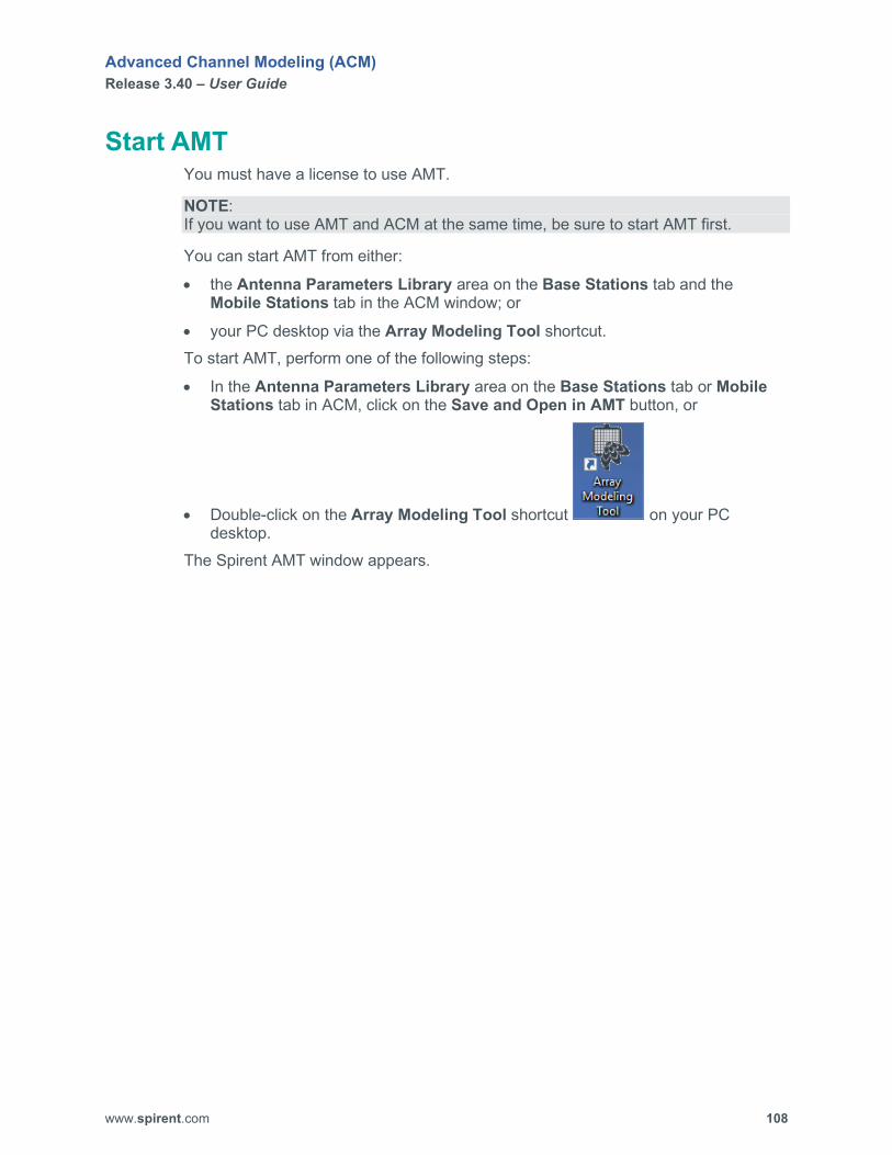
Advanced Channel Modeling (ACM) Release 3.40 – User Guide
www.spirent.com 108
Start AMT You must have a license to use AMT.
NOTE: If you want to use AMT and ACM at the same time, be sure to start AMT first.
You can start AMT from either:
• the Antenna Parameters Library area on the Base Stations tab and the Mobile Stations tab in the ACM window; or
• your PC desktop via the Array Modeling Tool shortcut. To start AMT, perform one of the following steps:
• In the Antenna Parameters Library area on the Base Stations tab or Mobile Stations tab in ACM, click on the Save and Open in AMT button, or
• Double-click on the Array Modeling Tool shortcut on your PC desktop.
The Spirent AMT window appears.

Advanced Channel Modeling (ACM) Release 3.40 – User Guide
www.spirent.com 109
Figure 72. Sample AMT window.
Advanced Channel Modeling (ACM) Release 3.40 – User Guide
www.spirent.com 110
Configure and Plot an Array To configure and plot an antenna array: 1. Start AMT.
The Spirent AMT window appears. 2. In the DL Frequency (MHz) box, enter your downlink frequency. 3. In the UL Frequency (MHz) box, enter your uplink frequency. 4. In the Units box, select the unit (Meters or Lambda). 5. Enter the element distance. 6. Specify the number of element rows. 7. Specify the number of element columns. 8. Specify whether there is a second slant. 9. Specify the Polarization Vector. 10. Configure any additional settings in which you are interested. If you want to
modify additional antenna settings, click on Antenna Settings and make your changes. If you want to load the settings from an existing antenna settings file, click the Load button, select the appropriate file, and then click the Open button. If you want to save the antenna settings to a file, click the Save button, enter the file name, and then click the Save button.
NOTE: If you modify any of the Beam Pointing Angles, be sure to click the Apply button next to the corresponding box so that your setting is saved.
11. When you are finished configuring the array settings, click the Plot button. 2D plots of the downlink (FL), uplink (RL), and polarization are displayed. If you specified more than 1 row of elements, 3D plots of the downlink (FL) and uplink (RL) are also displayed. Use the Rotate 3D button located at the top of the plot window to rotate the selected 3D plot. For 3D plots, blue indicates low amplitude, and red indicates high amplitude. The following figure shows a sample 2D plot of the downlink.

Advanced Channel Modeling (ACM) Release 3.40 – User Guide
www.spirent.com 111
Figure 73. Sample 2D downlink plot.
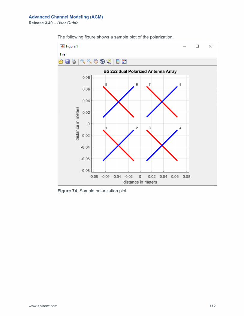
Advanced Channel Modeling (ACM) Release 3.40 – User Guide
www.spirent.com 112
The following figure shows a sample plot of the polarization.
Figure 74. Sample polarization plot.
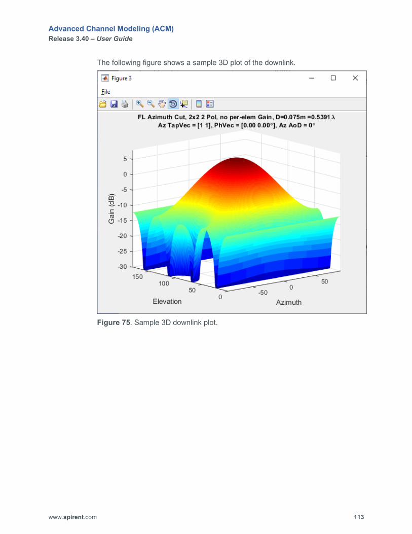
Advanced Channel Modeling (ACM) Release 3.40 – User Guide
www.spirent.com 113
The following figure shows a sample 3D plot of the downlink.
Figure 75. Sample 3D downlink plot.
Advanced Channel Modeling (ACM) Release 3.40 – User Guide
www.spirent.com 114
4. ACM Window Components
Overview This section describes the components of the ACM graphical user interface (GUI).
Base Stations tab The Base Stations tab enables you to configure the settings for up to 16 base stations. For each base station, you can configure frequency emulation mode, carrier frequency, location coordinates, height of the antenna above ground, transmit power, AWGN and carrier-to-noise ratio level, and antenna parameters such as theta tilt, theta down tilt, phi rotation, antenna pattern, and the configuration of the antenna array. The following figure shows a sample Base Stations tab.
NOTE: Mesh network scenarios and SAN scenarios do not contain base stations.
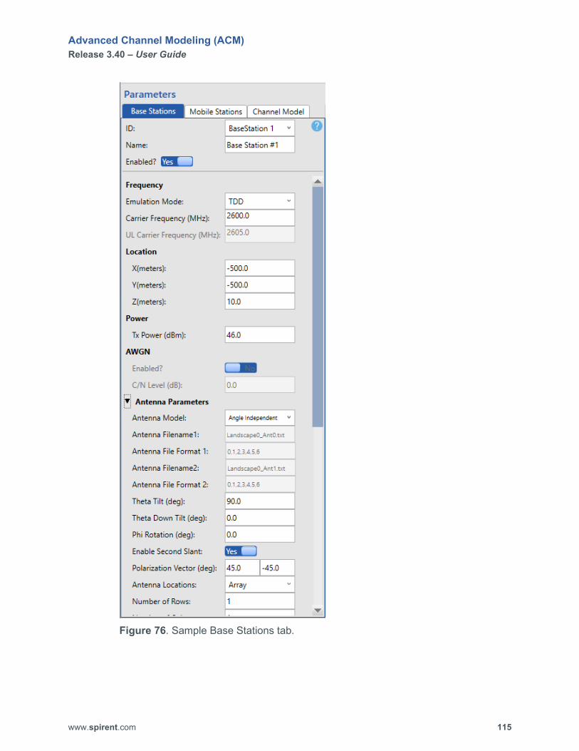
Advanced Channel Modeling (ACM) Release 3.40 – User Guide
www.spirent.com 115
Figure 76. Sample Base Stations tab.

Advanced Channel Modeling (ACM) Release 3.40 – User Guide
www.spirent.com 116
ID Select the base station you want to configure. Name Displays the name of the selected base station. You can customize this label. The name can consist of up to 25 characters. Enabled? Allows you to enable or disable the selected base station. Choices are Yes and No. MIMO OTA
Chamber Layout Select the chamber layout for a MIMO OTA scenario. In this release, only 6 Probes in a 3D Panel is supported.
Frequency Emulation Mode Select the frequency mode you want to use. Choices are FDD and TDD. Default is TDD. Carrier Frequency (MHz) (TDD mode) Specify the carrier frequency. This parameter is available when Emulation Mode is set to TDD. Range is 30.0 to 5925.0 MHz. Default is 2600.0. DL Carrier Frequency (MHz) (FDD mode) Specify the downlink carrier frequency. This parameter is available when Emulation Mode is set to FDD. Range is 30.0 to 5925.0 MHz. Default is 2600.0. UL Carrier Frequency (MHz) (FDD mode Specify the uplink carrier frequency. This parameter is available when Emulation Mode is set to FDD. Range is 30.0 to 5925.0 MHz. Default is 2605.0.
Location Enables you to specify the X,Y coordinates for the base station and the height of the antenna array above ground level.
X (meters) Specify the distance from origin in the X direction. Range is -10000.0 to 10000.0. Default is -500.0. Y (meters) Specify the distance from origin in the Y direction. Range is -10000.0 to 10000.0. Default is -500.0. Z (meters) Specify the height of the antenna array above ground level. Range is 0.0 to 10000.0. Default is 10.0.
Power Tx Power (dBm) Specify the transmit power. This setting affects the expected output level and therefore the estimated RSSI (Received Signal Strength Indicator). This setting does not affect path loss. Range is -110.0 to 100.0 dBm. Default is 46.0 dBm.

Advanced Channel Modeling (ACM) Release 3.40 – User Guide
www.spirent.com 117
AWGN Enabled? Allows you to enable or disable AWGN for the selected base station. When AWGN is enabled, this parameter sets the carrier to noise ratio as seen at the base station or mobile station. This parameter only applies when the Use Dynamic Level Adjustment setting is enabled on the Simulation Builder tab. Choices are Yes and No. C/N Level (dB) Specify the C/N (carrier-to-noise ratio) level. Range is -40.0 dB to 40.0 dB. However, the range is dependent on many parameters set on Vertex that ACM does not control. ACM allows you to enter a value down to -40 dB, but if Vertex cannot achieve this setting, it is flagged at compilation time. Default is 0.0 dB.
Antenna Parameters Antenna Model Specify the type of antenna model. Choices are ForeShortening, Angle Independent, and Read From File. Default is ForeShortening. Antenna Filename1 Select the text file that contains the antenna pattern of the vertical slants. This parameter is available when Antenna Model is set to Read From File. Default is Landscape_Ant0.txt. Antenna File Format 1 Enables you to arrange the columns of data in the selected file to match the expected order for ACM. For more information about using antenna files, see “Using Antenna Settings from a Text File” from a Text File on page 84. Antenna Filename2 Select the text file that contains the antenna pattern of the horizontal slants. This parameter is available when Antenna Model is set to Read From File. Default is Landscape_Ant1.txt. Antenna File Format 2 Enables you to arrange the columns of data in the selected file to match the expected order for ACM. For more information about using antenna files, see “Using Antenna Settings from a Text File” on page 84. Theta Tilt (deg) Specify the electrical tilt of the antenna pattern. Range is 0.0 to 180.0 degrees. Default is 90.0 degrees. 0.0 indicates no tilt. Theta Down Tilt (deg) Specify the mechanical tilt of the antenna pattern. Range is -90.0 to 90.0 degrees. Default is 0.0 degrees. 0.0 indicates the antenna pattern points to the horizon. 90.0 indicates the antenna pattern points to the south pole. -90.0 indicates the antenna pattern points to the north pole.
NOTE: The overall antenna pattern tilted down by the sum of both Theta Tilt and Theta Down Tilt. When the sum of both Theta Tilt and Theta Down Tilt is 0.0 degrees, the antenna pattern is pointing to the zenith. When it is tilted 90.0 degrees, the antenna pattern is pointing to the horizon.

Advanced Channel Modeling (ACM) Release 3.40 – User Guide
www.spirent.com 118
Phi Rotation (deg) Specify the mechanical rotation of the antenna array. Range is -180.0 to 180.0 degrees. Default is 45.0 degrees. 0.0 indicates the antenna array points to the X axis. Enable Second Slant Specify whether each antenna array location contains 2 slants. Choices are Yes and No. Default is Yes. Yes indicates each antenna array location contains 2 slants and they are co-centered (that is, “++”, ”XX”). No indicates each antenna array location contains 1 slant (“//”, ”\\”, ”||”, ”--“). Polarization Vector (deg) Specify the polarization vector for the antenna array slant. The left box sets the polarization vector for the first antenna array slant. The right box sets the polarization vector for the second antenna array slant. The right box is enabled if Enable Second Slant is set to Yes. Range is -180.0 to 180.0 degrees. Default for the first antenna array slant is 45.0 degrees. Default for the second antenna array slant is -45.0 degrees. Antenna Locations Select the antenna locations. Choices are Array and Arbitrary. Default is Array. Number of Rows Specify the number of rows in the antenna array. Range is 1 to 16. Default is 1 row. Number of Columns Specify the number of columns in the antenna array. Range is 1 to 16. Default is 1 column. Distance Units Specify the distance unit you want to use for the Distance Y and Distance Z settings. Choices are Lambda and Meters. Default is Lambda. Distance Y Specify the horizontal distance between adjacent antenna array elements that are in the same row of the antenna array. Range is > or = to 0. Default is 0.50. Distance Z Specify the vertical distance between adjacent antenna array elements that are in the same column of the antenna array. Range is > or = to 0. Default is 0.50. Slant Start Specify which of the 2 Polarization Vector parameters is indexed first. Choices are First Element and Second Element. First Element is the polarization vector for the first antenna array slant. Second Element is the polarization vector for the second antenna array slant. Default is First Element. Count Style Specify how the two antenna array slants are indexed. Choices are Count in Order and Count Same Slant First. Default is Count in Order. Count in Order indicates the two slants in the same location are indexed sequentially. Count Same Slant First indicates similarly slanted elements are indexed sequentially.

Advanced Channel Modeling (ACM) Release 3.40 – User Guide
www.spirent.com 119
First Value Specify whether the antenna elements indexing starts with 0 or 1. Choices are Count Starts at 0 and Count Starts at 1. Default is Count Starts at 1. Antenna Array Center Specify the phase reference, which can be located at any slant location. If set to -1, it will reference the Antenna Array Center, which is not a slant location when the antenna array includes an even number of slants. Default is -1. Normalized Vertical Gain Specify whether you want to use normalized vertical gain. Choices are Yes and No. Default is No. Remove self-normalization Specify whether you want to remove self-normalization. Choices are Yes and No. Default is Yes. Force AoDs To 0 Specify whether you want to ignore the paths azimuth angles of departure and replace them with 0 degrees. Choices are Yes and No. Default is No. Force ZoDs To 90 Specify whether you want to ignore the paths zenith angles of departure and replace them with 90 degrees. Choices are Yes and No. Default is No. Force UnCorrelated Specify whether there is no correlation between neighboring slants. Choices are Yes and No. Default is No. Normalize Output Power Specify whether you want to normalize output power. Choices are Yes and No. Default is No. Normalize Power Per Tap This box is enabled if Normalized Output Power is set to Yes. When this setting is enabled, the total power is set to 1, and the power tap is set to exactly match what was described by the Relative Path Loss on the Channel Model tab for each cluster. This feature is not available under some conditions. ACM will display a message for these conditions. Output Power Scale Factor Specify the output power scale factor. This box is enabled if Normalize Output Power is set to Yes. Range is 0.0 to 100.0. Default is 1.0. Apply Ant Pattern Specify whether to use the antenna pattern. Choices are Yes and No. Default is No. Az. Beam Width 3dB (deg) Specify the degrees at which the antenna pattern of the azimuth falls by 3dB. Range is 0.0 to 360.0 degrees. Default is 65.0 degrees. El. Beam Width 3dB (deg) Specify the degrees at which the antenna pattern of the elevation falls by 3dB. Range is 0.0 to 180.0 degrees. Default is 10.0 degrees.

Advanced Channel Modeling (ACM) Release 3.40 – User Guide
www.spirent.com 120
Max attenuation (dB) Specify the attenuation in the back side of the pattern. Range is 0 to 100dB. Default is 30.0dB. Max Directional Gain (dB) Specify the maximum gain of an individual element. Range is 0 to 100dB. Default is 8.0dB.
Antenna Parameters Library Load Enables you to load an existing antenna file. Save Enables you to save the antenna settings to a file. Save and Open in AMT Enables you to save the antenna settings to a file and open that file in the Spirent Array Modeling Tool (AMT).

Advanced Channel Modeling (ACM) Release 3.40 – User Guide
www.spirent.com 121
Mobile Stations tab The Mobile Stations tab enables you to configure the settings for up to 16 mobile stations. For each mobile station, you can configure motion type, vehicle type, motion repeat type, velocity, distance to be traveled, begin and end coordinates, transmit power, AWGN and carrier-to-noise ratio level, and antenna parameters such as theta down tilt, phi rotation, antenna pattern, and the configuration of the antenna array.
NOTE: MIMO OTA scenarios and SAN scenarios do not contain mobile stations.
The following figure shows a sample Mobile Stations tab.

Advanced Channel Modeling (ACM) Release 3.40 – User Guide
www.spirent.com 122
Figure 77. Sample Mobile Stations tab.

Advanced Channel Modeling (ACM) Release 3.40 – User Guide
www.spirent.com 123
ID Select the mobile station you want to configure. Name Displays the name of the selected mobile station. You can customize this label. The name can consist of up to 25 characters. Enabled? Allows you to enable or disable the selected mobile station. Choices are Yes and No. Location
Motion Type Specify the motion type for the mobile station. Choices are Static, Linear Motion, Circular Motion, and Piecewise Linear Motion. Default is Circular Motion. Vehicle Type Specify the vehicle type for the mobile station. Choices are Mobile, Car, Train, Airplane, Helicopter, and Drone. Default is Mobile. Vehicle Color Specify the vehicle color for the mobile station. This color will be displayed for the selected mobile station on the Network Layout tab. Choices are Lime, Tangerine, Smoke, Sky Blue, and Dark Blue. Default is Sky Blue. Motion Repeat Type This parameter is used when Motion Type is set to Linear Motion, Circular Motion, or Piecewise Linear Motion. Specify how the mobile station moves when it reaches its destination. Choices are Reverse Motion and Loop Motion. Default is Loop Motion. When Reverse Motion is selected, the mobile station reverses its motion and heads back to its starting point. When Loop Motion is selected, the mobile station resumes its motion from its starting point. Piecewise Definition File This parameter is used when Motion Type is set to Piecewise Linear Motion. Specify the text file that contains the Cartesian coordinates and velocity for each segment of the custom path you want to use.
NOTE: If you are using a piecewise linear motion path, you MUST set Auto Calculate Simulation Parameters? to No on the Simulation Builder tab before you build and play the scenario. X (meters) This parameter is used when Motion Type is set to Static. Specify the distance from origin in the X direction. Range is -10000 to 10000. Default is 0. Y (meters) This parameter is used when Motion Type is set to Static. Specify the distance from origin in the Y direction. Range is -10000 to 10000. Default is 0. Z (meters) This parameter is used when Motion Type is set to Static. Specify the height of the antenna array above ground level. Range is 0 to 10000. Default is 1.5.

Advanced Channel Modeling (ACM) Release 3.40 – User Guide
www.spirent.com 124
Start X (meters) This parameter is used when Motion Type is set to Linear. Specify the distance from origin in the X direction of the path start. Range is -10000 to 10000. Default is 0. Start Y (meters) This parameter is used when Motion Type is set to Linear. Specify the distance from origin in the Y direction of the path start. Range is -10000 to 10000. Default is 750. Start Z (meters) This parameter is used when Motion Type is set to Linear. Specify the height of the antenna array above ground level at the path start. Range is 0 to 10000. Default is 1.5. Origin X (meters) This parameter is used when Motion Type is set to Circular Motion. Specify the distance from origin in the X direction or the circle origin. Range is -10000 to 10000. Default is 0. Origin Y (meters) This parameter is used when Motion Type is set to Circular Motion. Specify the distance from origin in the Y direction of the circle origin. Range is -10000 to 10000. Default is 0. Origin Z (meters) This parameter is used when Motion Type is set to Circular Motion. Specify the height of the antenna array above ground level when starting. Range is 0 to 10000. Default is 1.5. Radius (meters) This parameter is used when Motion Type is set to Circular Motion. Specify radius of the circular motion path for the mobile station. Range is 0.0 to 2500. Default is 350. Start Angle (degrees) This parameter is used when Motion Type is set to Circular Motion. End Angle (degrees) This parameter is used when Motion Type is set to Circular Motion. Rotation Direction This parameter is used when Motion Type is set to Circular Motion. Specify the direction in which the mobile station moves along the circular path. Choices are Clockwise and Counter Clockwise. Default is Clockwise. End X (meters) This parameter is used when Motion Type is set to Linear. Specify the distance from origin in the X direction of the path end. Range is -10000 to 10000. Default is 500. End Y (meters) This parameter is used when Motion Type is set to Linear. Specify the distance from origin in the Y direction of the path end. Range is -10000 to 10000. Default is 1250.
Advanced Channel Modeling (ACM) Release 3.40 – User Guide
www.spirent.com 125
End Z (meters) This parameter is used when Motion Type is set to Linear. Specify the height of the antenna array above ground level at the path end. Range is 0 to 10000. Default is 1.5. Velocity Units Specify how you want to measure velocity of the mobile station. Choices are m/s, Km/h, and mph. Default is m/s. Velocity This parameter is used when Motion Type is set to Linear Motion or Circular Motion. Specify the speed at which the mobile station travels. Range is 0 to 500. Default is 20. Virtual Velocity This parameter is used when Motion Type is set to Static. Specify the magnitude of virtual velocity for the mobile station. Range is 0.01 to 500. Default is 8.33. Virtual Phi DoT (deg) This parameter is used when Motion Type is set to Static. Specify the virtual direction of the mobile station in the XY plane. Range is -180 to 180 degrees. Default is 120 degrees. Virtual Theta DoT (deg) This parameter is used when Motion Type is set to Static. Specify the virtual direction of the mobile station on the Z axis. . Range is 0 to 180 degrees. Default is 0 degrees. 0 points to the zenith. 90 points to the horizon.
Power Tx Power (dBm) Specify the transmit power. This setting affects the expected output level and therefore the estimated RSSI (Received Signal Strength Indicator). This setting does not affect path loss. Range is -110 to 100 dBm. Default is 24 dBm.
AWGN Enabled? Allows you to enable or disable AWGN for the selected mobile station. When AWGN is enabled, this parameter sets the carrier to noise ratio as seen at the base station or mobile station. This parameter only applies when the Use Dynamic Level Adjustment setting is enabled on the Simulation Builder tab. Choices are Yes and No. C/N Level (dB) Specify the C/N (carrier-to-noise ratio) level. Range is -40 dB to 40 dB. However, the range is dependent on many parameters set on Vertex that ACM does not control. ACM allows you to enter a value down to -40 dB, but if Vertex cannot achieve this setting, it is flagged at compilation time. Default is 0 dB.
Advanced Channel Modeling (ACM) Release 3.40 – User Guide
www.spirent.com 126
Antenna Parameters Antenna Model Specify the type of antenna model. Choices are ForeShortening, Angle Independent, and Read From File. Default is ForeShortening. Antenna Filename1 Select the text file that contains the antenna pattern of the vertical slants. This parameter is available when Antenna Model is set to Read From File. Default is Landscape0_Ant0.txt. Antenna File Format 1 Enables you to arrange the columns of data in the selected file to match the expected order for ACM. This parameter is available when Antenna Model is set to Read From File. For more information about using antenna files, see “Using Antenna Settings from a Text File” on page 84. Antenna Filename2 Select the text file that contains the antenna pattern of the horizontal slants. This parameter is available when Antenna Model is set to Read From File. Default is Landscape0_Ant1.txt. Antenna File Format 2 Enables you to arrange the columns of data in the selected file to match the expected order for ACM. This parameter is available when Antenna Model is set to Read From File. For more information about using antenna files, see “Using Antenna Settings from a Text File” on page 84. Antenna Filename3 Select the text file that contains the dipole settings. This parameter is available when Antenna Model is set to Read From File. Default is Ideal_dipole.txt. Antenna File Format 3 Enables you to arrange the columns of data in the selected file to match the expected order for ACM. This parameter is available when Antenna Model is set to Read From File. For more information about using antenna files, see “Using Antenna Settings from a Text File” on page 84. Antenna Filename4 Select the text file that contains the loop settings. This parameter is available when Antenna Model is set to Read From File. Default is Ideal_loop.txt. Antenna File Format 4 Enables you to arrange the columns of data in the selected file to match the expected order for ACM. This parameter is available when Antenna Model is set to Read From File. For more information about using antenna files, see “Using Antenna Settings from a Text File” on page 84. Theta Down Tilt (deg) Specify the mechanical tilt of the antenna array. Range is 0 to 180 degrees. Default is 90 degrees. 0 indicates the antenna array points to the zenith. 90 indicates the antenna array points to the horizon. Phi Rotation (deg) Specify the mechanical rotation of the antenna array. Range is -180 to 180 degrees. Default is 0 degrees. 0 indicates the antenna array points to the X axis.

Advanced Channel Modeling (ACM) Release 3.40 – User Guide
www.spirent.com 127
Enable Second Slant Specify whether each antenna array location contains 2 slants. Choices are Yes and No. Default is Yes. Yes indicates each of the antenna array locations contains 2 slants. No indicates each antenna array location contains 1 slant. Polarization Vector (deg) Specify the polarization vector for the antenna array slant. The left box sets the polarization vector for the first antenna array slant. The right box sets the polarization vector for the second antenna array slant. The right box is enabled if Enable Second Slant is set to Yes. Range is -180 to 180 degrees. Default for the first antenna array slant is 0 degrees. Default for the second antenna array slant is 90 degrees. Antenna Locations Specify the antenna location. Choices are Array and Arbitrary. Default is Array. Number of Rows Specify the number of rows in the antenna array. This parameter is used when Antenna Locations is set to Array. Range is 1 to 16. Default is 1 row. Number of Columns Specify the number of columns in the antenna array. This parameter is used when Antenna Locations is set to Array. Range is 1 to 16. Default is 1 column. Distance Units Specify the distance unit you want to use for the Distance Y and Distance Z settings. Choices are Lambda and Meters. Default is Lambda. Distance Y Specify the horizontal distance between adjacent antenna array elements that are in the same row of the antenna array. Range is > or = to 0. Default is 0.50. Distance Z Specify the vertical distance between adjacent antenna array elements that are in the same column of the antenna array. Range is > or = to 0. Default is 0.50. X Position Vector Specify the X coordinate for each antenna. This parameter is used when Antenna Locations is set to Arbitrary. Y Position Vector Specify the Y coordinate for each antenna. This parameter is used when Antenna Locations is set to Arbitrary. Z Position Vector Specify the Z coordinate for each antenna. This parameter is used when Antenna Locations is set to Arbitrary.

Advanced Channel Modeling (ACM) Release 3.40 – User Guide
www.spirent.com 128
Antenna Array Center Specify the phase reference, which can be located at any slant location. Range is -1 to array dimension. If set to -1, it will reference the Antenna Array Center, which is not a slant location when the antenna array includes an even number of slants. Default is -1. Force UnCorrelated Specify whether there is no correlation between neighboring slants. Choices are Yes and No. Default is No.
Antenna Parameters Library Load Enables you to load an existing antenna file. Save Enables you to save the antenna settings to a file. Save and Open in AMT Enables you to save the antenna settings to a file and open that file in the Spirent Array Modeling Tool (AMT).

Advanced Channel Modeling (ACM) Release 3.40 – User Guide
www.spirent.com 129
Channel Model tab The Channel Model tab enables you to configure the channel model settings for each channel. A channel ID consists of the base station number and the mobile station number. For each channel ID, you can set downlink status, uplink status, and select either a predefined channel model such as SCME UMi, SCME UMa, High Speed Train, CDL-A, CDL-B, CDL-C, CDL-D, CDL-E, TDL-A, TDL-B, and TDL-C or create and save a custom configuration. In a custom configuration, you configure parameters such as power angle spectrum, street width, average building height, paths and midpaths settings, cluster settings, and scaling factors. Custom path loss models are supported. To save your custom channel model, click the Customize button on the Channel/Path Views tab. Using the Customize button, you can create a library of custom channel models. To access your custom channel models, select Custom from the Channel Model box on the Channel Model tab and click the Load button on the Channel/Path Views tab. The following figure shows a sample Channel Model tab.
Figure 78. Sample Channel Model tab. Channel ID Select the channel you want to configure. Channels are labeled by their connection, making it easier for you to identify channels. (For example, the connection from base station 1 to mobile station 1 is labeled BS1-MS1.) Channel Model Specify the model for the selected channel. Choices are SCME UMi, SCME UMa, High Speed Train, CDL-A, CDL-B, CDL-C, CDL-D, CDL-E, Custom, TDL-A, TDL-B, and TDL-C. Default is SCME UMi.

Advanced Channel Modeling (ACM) Release 3.40 – User Guide
www.spirent.com 130
NOTE: In this release, the SAN scenario supports only TDL-A, TDL-B, TDL-C, and Custom.
Downlink Enabled? Allows you to enable or disable the downlink for the selected channel. Choices are Yes and No. Default is Yes. Uplink Enabled? Allows you to enable or disable the uplink for the selected channel. Choices are Yes and No. Default is No. XPR (dB) Specify the cross polarization ratio, which measures the correlation between the horizontal and vertical elements. Range is 0 to 200 dB. Default is 8 dB. Line of sight? Specify whether there is line of sight beam between the base station and the mobile station. Choices are Yes and No. Default is No. Decouple LOS/Clusters Specify whether you want to decouple LOS/clusters. Choices are Yes and No. Default is No. K Factor Method This setting is used when Channel Model is set to High Speed Train, CDL-D, and CDL-E. (There are 3 different methods to define the K factor when a channel is set to LOS.) Choices are:
• Path 1 Only: The K factor is equal to the power in LOS part divided by the power in the NLOS part of the first path only.
• All Paths: The K factor is equal to the power in the LOS part in the first path divided by the power in the NLOS part of all paths.
• Ray Power: WINNER and WINNER II style. Default is All Paths. K Factor (dB), Overall (dB)/Path 1 (dB) This setting is used when K-Factor Method is set to Path 1 Only or All Paths. Ray Power (dB) This setting is used when K-Factor Method is set to Ray Power. Use Model Specify whether the geometric model is based on 3GPP recommendation 36.873 or 38.901. Choices are 36.873 and 38.901. Default is 36.873. Fading Method Specify the fading method you want to use. Choices are Sum of Sinusoids and Filtered Noise. Default is Sum of Sinusoids. Path Loss Model Specify the path loss model you want to use. Choices are Standard and Custom. Default is Standard.

Advanced Channel Modeling (ACM) Release 3.40 – User Guide
www.spirent.com 131
Intercept This parameter and Propagation Exponent enable arbitrary path loss models when expressed as follows: PathLoss = Intercept + 10* Propagation_Exponent*Log10(Dist_3d) This setting is used when Path Loss Model is set to Custom. Propagation Exponent This parameter and Intercept enable arbitrary path loss models when expressed as follows: PathLoss = Intercept + 10* Propagation_Exponent*Log10(Dist_3d) This setting is used when Path Loss Model is set to Custom. Common Parameters You can modify these parameters when Channel Model is set to Custom. These settings are only available when Channel Model is set to Custom.
Power Angle Spectrum Statistical distribution of angle spread. Setting is Laplacian. Zero LOS Phase? Choices are Yes and No. Default is Yes. Street Width Specify the street width that the mobile is traversing in meters. Only applicable when 36.873 is selected. Range is 5 to 50. Default is 20. Average Building Height Specify the average building height in the vicinity of the mobile in meters. Only applicable when 36.873 is selected. Range is 5 to 50. Default is 20. Dimensions Specify whether the geometrical model is 2D (ignoring heights) or 3D. Choices are 2D and 3D. Default is 3D.
Paths and Midpaths Sinusoids Per Path Specify the total number of sinusoids per path (sum of the number of sinusoids per midpath, if midpaths are present). Choices are 20, 40, 60, 100, and 300. Default is 20. Use Delay 2 Vector? Enables you to specify arbitrary delay setting for the midpaths. Some 38.901 models have had common angle paths converted to midpaths, however the delays are unique. This 2 vector input allows you to add the unique values to the model. Midpath 1 Power (%) Specify the percent of the path power assigned to each midpath. Range is 0 to 100%. Default is 50%. Midpath 1 Delay 1 (ns) Specify the delay of each midpath, compared to the lowest delay midpath. Range is 0 to 100000 ns. Default is 0 ns.

Advanced Channel Modeling (ACM) Release 3.40 – User Guide
www.spirent.com 132
Midpath 1 Delay 2 (ns) This setting is available if Use Delay 2 Vector? is set to Yes. Specify the delay of each midpath, compared to the lowest delay midpath. Range is 0 to 100000 ns. Default is 0 ns. Midpath 1 Sin (#) Specify how many sinusoids are assigned to each midpath. Range is 0 to number sinusoids per path. Default is 10. Midpath 2 Power (%) Specify the percent of the path power assigned to each midpath. Range is 0 to 100%. Default is 30%. Midpath 2 Delay 1 (ns) Specify the delay of each midpath, compared to the lowest delay midpath. Range is 0 to 100000 ns. Default is 5 ns. Midpath 2 Delay 2 (ns) This parameter is available if Use Delay 2 Vector? is set to Yes. Specify the delay of each midpath, compared to the lowest delay midpath. Range is 0 to 100000 ns. Default is 5 ns. Midpath 2 Sin (#) Specify how many sinusoids are assigned to each midpath. Range is 0 to number sinusoids per path. Default is 6. Midpath 3 Power (%) Specify the percent of the path power assigned to each midpath. Range is 0 to 100%. Default is 20%. Midpath 3 Delay 1 (ns) Specify the delay of each midpath, compared to the lowest delay midpath. Range is 0 to 100000 ns. Default is 10 ns. Midpath 3 Delay 2 (ns) This setting is available if Use Delay 2 Vector? is set to Yes. Specify the delay of each midpath, compared to the lowest delay midpath. Range is 0 to 100000 ns. Default is 10 ns.. Midpath 3 Sin (#) Specify how many sinusoids are assigned to each midpath. Range is 0 to number sinusoids per path. Default is 4. Total The sum of the number of sinusoids of the three midpaths should equal the number of sinusoids per path. Use Polarity Phase File? Choices are Yes and No. Default is No. Polarity Phase Filename Select the text file that contains the polarity phase. This parameter is available when Use Polarity Phase File? is set to Yes. Default is Pol_phase_table_20_sines_6_path.txt.

Advanced Channel Modeling (ACM) Release 3.40 – User Guide
www.spirent.com 133
Subpath Assign Type Choices are Rand, Read File, and Linear. Subpath Assign Filename Select the text file that contains subpath assign. This parameter is available when Subpath Assign Type is set to Read File. Default is Subpath_assignment_20_sines_6_path.txt. Use Subpath Angles File? Choices are Yes and No. Default is No. Subpath Angles Filename Select the text file that contains subpath angles. This parameter is available when Use Subpath Angles File? is set to Yes. Default is Subpath_angles_20_sines_6.txt. Use Midpath Map File? Choices are Yes and No. Default is No. Midpath Map Filename Select the text file that contains the midpath map. This parameter is available when Use Midpath Map File? is set to Yes. Default is Midpath_map_20_sines.txt.
Cluster These parameters are only available when Use Model is set to 38.901.
Cluster DS (nSec) Specify the intra-cluster delay spread. This parameter is only available when Use Model is set to 38.901. Range is 0 to 300 nSec. Default is 3.91 nSec. Distance 3D (m) Specify the 3D distance between two points. This parameter is only available when Use Model is set to 38.901. Range is 0 to 300 m. Default is 100 m. Delay Spread Scaling? When set to Yes, this setting enables you to set the desired rms delay spread. The resulting delays in the channel model are calculated as the product of the DS Desired parameter and the delays of the channel model. Delay values are entered in ns. For example, to set the resulting DS to 135ns, enter the number 135. This setting is only available when Use Model is set to 38.901. DS Desired (nSec) Specify the desired channel delay spread. This parameter is only available when Use Model is set to 38.901. Range is 0 to 300 nSec. Default is 100 nSec.
Advanced Channel Modeling (ACM) Release 3.40 – User Guide
www.spirent.com 134
Scaling Factors These parameters are only available when Use Model is set to 38.901.
ASA Desired (deg) Specify the desired angle of arrival spread. This parameter is only available when Use Model is set to 38.901. Range is -1 to 180 degrees. Default is -1 degree. ASD Desired (deg) Specify the desired angle of departure spread. This parameter is only available when Use Model is set to 38.901. Range is -1 to 180 degrees. Default is -1 degree. ZSA Desired (deg) Specify the desired elevation angle of arrival spread. This parameter is only available when Use Model is set to 38.901. Range is -1 to 180 degrees. Default is -1 degree. ZSD Desired (deg) Specify the desired elevation angle of departure spread. This parameter is only available when Use Model is set to 38.901. Range is -1 to 180 degrees. Default is -1 degree. AoA Offset (deg) Specify the angle of arrival offset. This parameter is only available when Use Model is set to 38.901. Range is -180 to 180 degrees. Default is 0 degree. AoD Offset (deg) Specify the angle of departure offset. This parameter is only available when Use Model is set to 38.901. Range is -180 to 180 degrees. Default is 0 degree. ZoA Offset (deg) Specify the elevation angle of arrival offset. This parameter is only available when Use Model is set to 38.901. Range is -180 to 180 degrees. Default is 0 degree. ZoD Offset (deg) Specify the elevation angle of departure offset. This parameter is only available when Use Model is set to 38.901. Range is -180 to 180 degrees. Default is 0 degree.

Advanced Channel Modeling (ACM) Release 3.40 – User Guide
www.spirent.com 135
Mesh tab The Mesh tab enables you to configure the frequency emulation mode, carrier frequency, and mesh network configuration for the mesh network scenario. The following figure shows a sample Mesh tab.
Figure 79. Sample Mesh tab.
Frequency area Emulation Mode Select the frequency mode you want to use. Choices are FDD and TDD. Default is TDD. This frequency mode applies to all mobile stations (nodes) in the mesh network scenario. Carrier Frequency (MHz) Specify the carrier frequency. Range is 30 to 5925 MHz. Default is 2600.
Mesh Configuration area Configuration Select the mesh network configuration you want to use. Choices are: Full Mesh Star Loop Convoy Custom
NOTE: Custom is not selectable. It appears when you create a mesh configuration that is something other than Full Mesh, Star, Loop, or Convoy.
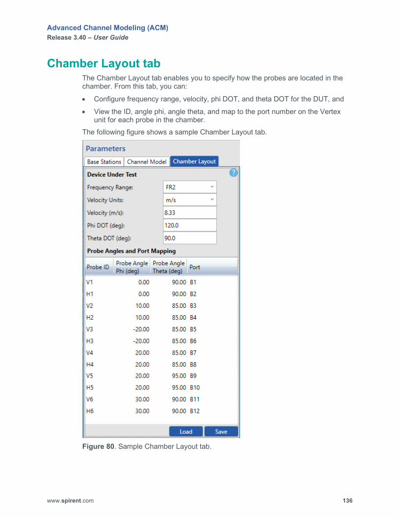
Advanced Channel Modeling (ACM) Release 3.40 – User Guide
www.spirent.com 136
Chamber Layout tab The Chamber Layout tab enables you to specify how the probes are located in the chamber. From this tab, you can:
• Configure frequency range, velocity, phi DOT, and theta DOT for the DUT, and
• View the ID, angle phi, angle theta, and map to the port number on the Vertex unit for each probe in the chamber.
The following figure shows a sample Chamber Layout tab.
Figure 80. Sample Chamber Layout tab.
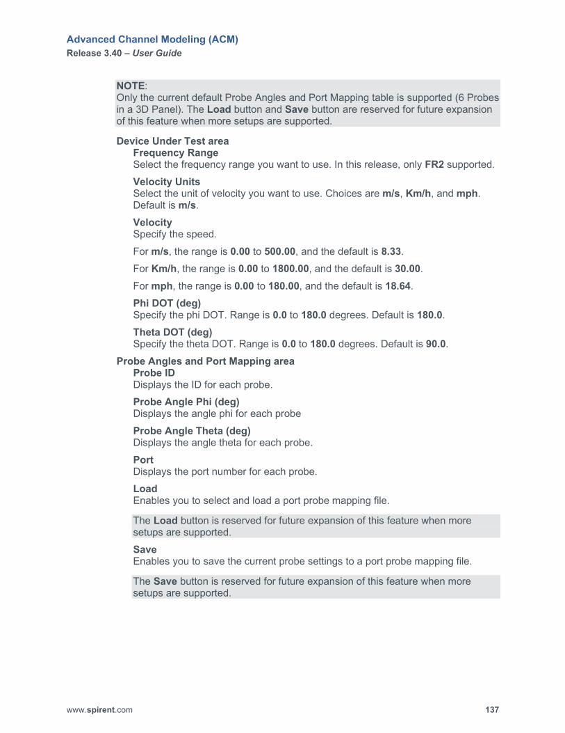
Advanced Channel Modeling (ACM) Release 3.40 – User Guide
www.spirent.com 137
NOTE: Only the current default Probe Angles and Port Mapping table is supported (6 Probes in a 3D Panel). The Load button and Save button are reserved for future expansion of this feature when more setups are supported.
Device Under Test area Frequency Range Select the frequency range you want to use. In this release, only FR2 supported. Velocity Units Select the unit of velocity you want to use. Choices are m/s, Km/h, and mph. Default is m/s. Velocity Specify the speed. For m/s, the range is 0.00 to 500.00, and the default is 8.33. For Km/h, the range is 0.00 to 1800.00, and the default is 30.00. For mph, the range is 0.00 to 180.00, and the default is 18.64. Phi DOT (deg) Specify the phi DOT. Range is 0.0 to 180.0 degrees. Default is 180.0. Theta DOT (deg) Specify the theta DOT. Range is 0.0 to 180.0 degrees. Default is 90.0.
Probe Angles and Port Mapping area Probe ID Displays the ID for each probe. Probe Angle Phi (deg) Displays the angle phi for each probe Probe Angle Theta (deg) Displays the angle theta for each probe. Port Displays the port number for each probe. Load Enables you to select and load a port probe mapping file.
The Load button is reserved for future expansion of this feature when more setups are supported. Save Enables you to save the current probe settings to a port probe mapping file.
The Save button is reserved for future expansion of this feature when more setups are supported.

Advanced Channel Modeling (ACM) Release 3.40 – User Guide
www.spirent.com 138
SAN tab – Sinusoidal scenario The SAN tab enables you to configure the following settings for a Sinusoidal scenario:
• Time length of the emulation,
• Sampling time,
• Maximum Doppler,
• Maximum range of the satellite,
• Minimum range of the satellite,
• Minimum loss,
• Settings for up to 4 satellites (name, ID, speed, and number of antennas), and
• Settings for up to 4 observers (name, ID, emulation mode, DL carrier frequency, UL carrier frequency, and number of antennas).
The following figure shows a sample SAN tab for a Sinusoidal scenario.

Advanced Channel Modeling (ACM) Release 3.40 – User Guide
www.spirent.com 139
Figure 81. Sample SAN tab for a Sinusoidal scenario.

Advanced Channel Modeling (ACM) Release 3.40 – User Guide
www.spirent.com 140
Scenario Type Select the scenario you want to configure. Choices are:
• Sinusoidal • Linear Constant Speed • Linear Accelerating Speed • Elliptical • Random Movement • Geostationary • Field to Lab • GPS Scenario Settings area
Emulation Time Length (sec) Specify the length of time for the emulation. Range is 1.0 to 3600.0 seconds. Default is 60.0. Sampling Time (sec) Specify the DEE sampling time. Range is 1.0 to 10.0 second. Default is 1.0. Max Doppler (Hz) Specify the maximum (peak) Doppler. Range is 0.1 to 2000000.0 MHz. Default is 1000. Max Range (km) Specify the maximum distance of the satellite to the observer. Range is 0.1 to100000.0 km. Default is 4000.0. Min Range (km) Specify the minimum distance of the satellite to the observer. Range is 0.1 to 100000.0 km. Default is 2000.0. Minimum Loss (dB) Specify the minimum loss. Range is 0 to 50 dB. Default is 10.0.
Satellites area Satellite ID Select the satellite you want to configure. You can configure up to 4 satellites for a scenario. Name Displays the name of the selected satellite. You can customize this label. The name can consist of up to 25 characters. Enabled? Allows you to enable or disable the selected satellite. Choices are Yes and No. Satellite Speed (km/hr) Specify the speed of the satellite. Range is 0.1 to 30000.0 km/hr. Default is 25000.0.

Advanced Channel Modeling (ACM) Release 3.40 – User Guide
www.spirent.com 141
# Antennas Specify the number of antennas on the satellite. Choices are 1, 2, and 4. Default is 1.
Observers area Observer ID Select the observer you want to configure. You can configure up to 4 observers for a scenario. Name Displays the name of the selected observer. You can customize this label. The name can consist of up to 25 characters. Enabled? Allows you to enable or disable the selected observer. Choices are Yes and No. Emulation Mode Select the frequency mode you want to use for the observer. Choices are FDD and TDD. Default is FDD. DL Carrier Freq (MHz) Specify the downlink carrier frequency for the observer. Range is 30.0 to 5925.0 MHz. Default is 2600.0. UL Carrier Freq (MHz) Specify the uplink carrier frequency for the observer. Range is 30.0 to 5925.0 MHz. Default is 2700.0. # Antennas Specify the number of antennas on the observer. Choices are 1, 2, and 4. Default is 1. Note that the number of observer antennas always matches the number of satellite antennas.

Advanced Channel Modeling (ACM) Release 3.40 – User Guide
www.spirent.com 142
SAN tab – Linear Constant Speed scenario The SAN tab enables you to configure the following settings for a Linear Constant Speed scenario:
• Maximum Doppler,
• Maximum range of the satellite,
• Minimum range of the satellite,
• Upsampling factor,
• Minimum loss,
• Settings for up to 4 satellites (name, ID, velocity, and number of antennas), and
• Settings for up to 4 observers (name, ID, emulation mode, DL carrier frequency, UL carrier frequency, and number of antennas).
The following figure shows a sample SAN tab for a Linear Constant Speed scenario.

Advanced Channel Modeling (ACM) Release 3.40 – User Guide
www.spirent.com 143
Figure 82. Sample SAN tab for a Linear Constant Speed scenario.

Advanced Channel Modeling (ACM) Release 3.40 – User Guide
www.spirent.com 144
Scenario Type Select the scenario you want to configure. Choices are:
• Sinusoidal • Linear Constant Speed • Linear Accelerating Speed • Elliptical • Random Movement • Geostationary • Field to Lab • GPS Scenario Settings area
Max Doppler (Hz) Specify the maximum Doppler. Range is 0.1 to 2000000.0 MHz. Default is 1000. Max Range (km) Specify the maximum distance of the satellite to the observer. Range is 0.1 to100000.0 km. Default is 4000.0. Min Range (km) Specify the minimum distance of the satellite to the observer. Range is 0.1 to 100000.0 km. Default is 2000.0. Upsampling Factor Specify the upsampling factor. Choices are None, 8, 16, and 64. Default is None. Minimum Loss (dB) Specify the minimum loss. Range is 0 to 50 dB. Default is 10.0.
Satellites area Satellite ID Select the satellite you want to configure. You can configure up to 4 satellites for a scenario. Name Displays the name of the selected satellite. You can customize this label. The name can consist of up to 25 characters. Enabled? Allows you to enable or disable the selected satellite. Choices are Yes and No. Satellite Velocity (km/hr) Specify the velocity of the satellite. Range is 0.1 to 30000.0 km/hr. Default is 25000.0. # Antennas Specify the number of antennas on the satellite. Choices are 1, 2, and 4. Default is 1.

Advanced Channel Modeling (ACM) Release 3.40 – User Guide
www.spirent.com 145
Observers area Observer ID Select the observer you want to configure. You can configure up to 4 observers for a scenario. Name Displays the name of the selected observer. You can customize this label. The name can consist of up to 25 characters. Enabled? Allows you to enable or disable the selected observer. Choices are Yes and No. Emulation Mode Select the frequency mode you want to use for the observer. Choices are FDD and TDD. Default is FDD. DL Carrier Freq (MHz) Specify the downlink carrier frequency for the observer. Range is 30.0 to 5925.0 MHz. Default is 2600.0. UL Carrier Freq (MHz) Specify the uplink carrier frequency for the observer. Range is 30.0 to 5925.0 MHz. Default is 2700.0. # Antennas Specify the number of antennas on the observer. Choices are 1, 2, and 4. Default is 1. Note that the number of observer antennas always matches the number of satellite antennas.

Advanced Channel Modeling (ACM) Release 3.40 – User Guide
www.spirent.com 146
SAN tab – Linear Accelerating Speed scenario The SAN tab enables you to configure the following settings for a Line Accelerating Speed scenario:
• Maximum Doppler,
• Maximum range of the satellite,
• Minimum range of the satellite,
• Upsampling factor,
• Minimum loss,
• Settings for up to 4 satellites (name, ID, initial velocity, acceleration, and number of antennas), and
• Settings for up to 4 observers (name, ID, emulation mode, DL carrier frequency, UL carrier frequency, and number of antennas).
The following figure shows a sample SAN tab for a Linear Accelerating Speed scenario.

Advanced Channel Modeling (ACM) Release 3.40 – User Guide
www.spirent.com 147
Figure 83. Sample SAN tab for a Linear Accelerating Speed scenario.

Advanced Channel Modeling (ACM) Release 3.40 – User Guide
www.spirent.com 148
Scenario Type Select the scenario you want to configure. Choices are:
• Sinusoidal • Linear Constant Speed • Linear Accelerating Speed • Elliptical • Random Movement • Geostationary • Field to Lab • GPS Scenario Settings area
Max Doppler (Hz) Specify the maximum Doppler. Range is 0.1 to 2000000.0 MHz. Default is 1000. Max Range (km) Specify the maximum distance of the satellite to the observer. Range is 0.1 to100000.0 km. Default is 4000.0. Min Range (km) Specify the minimum distance of the satellite to the observer. Range is 0.1 to 100000.0 km. Default is 2000.0. Upsampling Factor Specify the upsampling factor. Choices are None, 8, 16, and 64. Default is None. Minimum Loss (dB) Specify the minimum loss. Range is 0 to 50 dB. Default is 10.0.
Satellites area Satellite ID Select the satellite you want to configure. You can configure up to 4 satellites for a scenario. Name Displays the name of the selected satellite. You can customize this label. The name can consist of up to 25 characters. Enabled? Allows you to enable or disable the selected satellite. Choices are Yes and No. Initial Velocity (km/hr) Specify the initial velocity of the satellite. Range is 0.1 to 30000.0 km/hr. Default is 25000.0. Acceleration (m/s/s) Specify the speed of acceleration of the satellite. Range is 1.0 to 1000.0 km/hr. Default is 10.0.

Advanced Channel Modeling (ACM) Release 3.40 – User Guide
www.spirent.com 149
# Antennas Specify the number of antennas on the satellite. Choices are 1, 2, and 4. Default is 1.
Observers area Observer ID Select the observer you want to configure. You can configure up to 4 observers for a scenario. Name Displays the name of the selected observer. You can customize this label. The name can consist of up to 25 characters. Enabled? Allows you to enable or disable the selected observer. Choices are Yes and No. Emulation Mode Select the frequency mode you want to use for the observer. Choices are FDD and TDD. Default is FDD. DL Carrier Freq (MHz) Specify the downlink carrier frequency for the observer. Range is 30.0 to 5925.0 MHz. Default is 2600.0. UL Carrier Freq (MHz) Specify the uplink carrier frequency for the observer. Range is 30.0 to 5925.0 MHz. Default is 2700.0. # Antennas Specify the number of antennas on the observer. Choices are 1, 2, and 4. Default is 1. Note that the number of observer antennas always matches the number of satellite antennas.

Advanced Channel Modeling (ACM) Release 3.40 – User Guide
www.spirent.com 150
SAN tab – Elliptical scenario The SAN tab enables you to configure the following settings for an Elliptical scenario:
• Sampling time,
• Number of points,
• Minimum loss,
• Settings for up to 4 satellites (name, ID, X, Y, and Z for center, X, Y, and Z for radius, and number of antennas), and
• Settings for up to 4 observers (name, ID, emulation mode, DL carrier frequency, UL carrier frequency, X, Y, and Z for position, and number of antennas).
The following figure shows a sample SAN tab for an Elliptical scenario.

Advanced Channel Modeling (ACM) Release 3.40 – User Guide
www.spirent.com 151
Figure 84. Sample SAN tab for an Elliptical scenario.

Advanced Channel Modeling (ACM) Release 3.40 – User Guide
www.spirent.com 152
Scenario Type Select the scenario you want to configure. Choices are:
• Sinusoidal • Linear Constant Speed • Linear Accelerating Speed • Elliptical • Random Movement • Geostationary • Field to Lab • GPS Scenario Settings area
Sampling Time (sec) Specify the sampling time of the DEE file. (For example, if you set the sampling time to 0.01, DEE will sample every 0.01 seconds.) Range is 0.01 to 10.0 second. Default is 1.0. Number of Points Specify the number of points in the ellipsoid. Range is 100 to 10000. Default is 1000. Minimum Loss (dB) Specify the minimum loss. Range is 0 to 50 dB. Default is 10.0.
Satellites area Satellite ID Select the satellite you want to configure. You can configure up to 4 satellites for a scenario. Name Displays the name of the selected satellite. You can customize this label. The name can consist of up to 25 characters. Enabled? Allows you to enable or disable the selected satellite. Choices are Yes and No. X Center (km) Specify the X coordinate of the center of the ellipsoid of the satellite. Range is 0.0 to 100000.0 km. Default is 10000.0. Y Center (km) Specify the Y coordinate of the center of the ellipsoid of the satellite. Range is 0.0 to 100000.0 km. Default is 10000.0. Z Center (km) Specify the Z coordinate of the center of the ellipsoid of satellite. Range is 0.0 to 100000.0 km. Default is 10000.0. X Radius (km) Specify the radius of the ellipsoid in the X direction. Range is 0.0 to 100000.0 km. Default is 10000.0.

Advanced Channel Modeling (ACM) Release 3.40 – User Guide
www.spirent.com 153
Y Radius (km) Specify the radius of the ellipsoid in the Y direction. Range is 0.0 to 100000.0 km. Default is 10000.0. Z Radius (km) Specify the radius of the ellipsoid in the Z direction. Range is 0.0 to 100000.0 km. Default is 10000.0. # Antennas Specify the number of antennas on the satellite. Choices are 1, 2, and 4. Default is 1.
Observers area Observer ID Select the observer you want to configure. You can configure up to 4 observers for a scenario. Name Displays the name of the selected observer. You can customize this label. The name can consist of up to 25 characters. Enabled? Allows you to enable or disable the selected observer. Choices are Yes and No. Emulation Mode Select the frequency mode you want to use for the observer. Choices are FDD and TDD. Default is FDD. DL Carrier Freq (MHz) Specify the downlink carrier frequency for the observer. Range is 30.0 to 5925.0 MHz. Default is 2600.0. UL Carrier Freq (MHz) Specify the uplink carrier frequency for the observer. Range is 30.0 to 5925.0 MHz. Default is 2700.0. X Position (km) Specify the X coordinate of the observer. Range is 0.0 to 100000.0 km. Default is 10000.0. Y Position (km) Specify the Y coordinate of the observer. Range is 0.0 to 100000.0 km. Default is -2000.0. Z Position (km) Specify the Z coordinate of the observer. Range is 0.0 to 100000.0 km. Default is 10.0. # Antennas Specify the number of antennas on the observer. Choices are 1, 2, and 4. Default is 1. Note that the number of observer antennas always matches the number of satellite antennas.
Advanced Channel Modeling (ACM) Release 3.40 – User Guide
www.spirent.com 154
SAN tab – Random Movement scenario The SAN tab enables you to configure the following settings for a Random Movement scenario:
• Time length of the emulation,
• Sampling time,
• Forget factor theta,
• Forget factor phi,
• Maximum altitude of the satellite,
• Minimum altitude of the satellite,
• Theta,
• Sigma,
• Minimum loss,
• Settings for up to 4 satellites (name, ID, random seed, speed, and number of antennas), and
• Settings for up to 4 observers (name, ID, random seed, emulation mode, DL carrier frequency, UL carrier frequency, X, Y, and Z for position, speed, and number of antennas).
The following figure shows a sample SAN tab for a Random Movement scenario.

Advanced Channel Modeling (ACM) Release 3.40 – User Guide
www.spirent.com 155
Figure 85. Sample SAN tab for a Random Movement scenario.

Advanced Channel Modeling (ACM) Release 3.40 – User Guide
www.spirent.com 156
Scenario Type Select the scenario you want to configure. Choices are:
• Sinusoidal • Linear Constant Speed • Linear Accelerating Speed • Elliptical • Random Movement • Geostationary • Field to Lab • GPS Scenario Settings area
Emulation Time Length (sec) Specify the length of time for the emulation. Range is 1.0 to 3600.0 seconds. Default is 60.0. Sampling Time (sec) Specify the sampling time. Range is 1.0 to 10.0 seconds. Default is 1.0. Forget Factor Theta Specify the forgetting factor of satellite azimuth steering, which is needed to smoothly steer the elevation. Range is 0.1 to 1.0. Default is 0.5. Forget Factor Phi Specify the forgetting factor of satellite azimuth steering, which is needed to smoothly steer the azimuth. Range is 0.1 to 1.0. Default is 0.5. Max Altitude (km) Specify the maximum altitude of the satellite. Range is 100.0 to 100000.0 km. Default is 200.0. Min Altitude (km) Specify the minimum altitude of the satellite. Range is 100.0 to 100000.0 km. Default is 100.0. Theta Specify the satellite standard (sigma) azimuth angle change (degrees). Range is 0.0 to 10.0. Default is 3.0. Sigma Specify how wide the distribution is. Range is 30 to 5925 MHz. Default is 10.0. Minimum Loss (dB) Specify the minimum loss. Range is 0 to 50 dB. Default is 10.0.

Advanced Channel Modeling (ACM) Release 3.40 – User Guide
www.spirent.com 157
Satellites area Satellite ID Select the satellite you want to configure. You can configure up to 4 satellites for a scenario. Name Displays the name of the selected satellite. You can customize this label. The name can consist of up to 25 characters. Enabled? Allows you to enable or disable the selected satellite. Choices are Yes and No. Random Seed Specify the random sequence. Range is -2,147,483,648 to 2,147,483,647. Default is 1. Satellite Speed (km/hr) Specify the speed of the satellite. Range is 0.1 to 30000.0 km/hr. Default is 25000.0. # Antennas Specify the number of antennas on the satellite. Choices are 1, 2, and 4. Default is 1.
Observers area Observer ID Select the observer you want to configure. You can configure up to 4 observers for a scenario. Name Displays the name of the selected observer. You can customize this label. The name can consist of up to 25 characters. Enabled? Allows you to enable or disable the selected observer. Choices are Yes and No. Random Seed Specify the random sequence. Range is -2,147,483,648 to 2,147,483,647. Default is 1. Emulation Mode Select the frequency mode you want to use for the observer. Choices are FDD and TDD. Default is TDD. DL Carrier Freq (MHz) Specify the downlink carrier frequency for the observer. Range is 30.0 to 5925.0 MHz. Default is 2600.0. UL Carrier Freq (MHz) Specify the uplink carrier frequency for the observer. Range is 30.0 to 5925.0 MHz. Default is 2700.0. X Position (km) Specify the X coordinate of the observer. Range is 0.0 to 100000.0 km. Default is 10000.0.

Advanced Channel Modeling (ACM) Release 3.40 – User Guide
www.spirent.com 158
Y Position (km) Specify the Y coordinate of the observer. Range is 0.0 to 100000.0 km. Default is -2000.0. Z Position (km) Specify the Z coordinate of the observer. Range is 0.0 to 100000.0 km. Default is 10.0. Observer Speed (km/hr) Specify the speed of the observer. Range is 0.1 to 30000.0 km/hr. Default is 100.0. # Antennas Specify the number of antennas on the observer. Choices are 1, 2, and 4. Default is 1. Note that the number of observer antennas always matches the number of satellite antennas.

Advanced Channel Modeling (ACM) Release 3.40 – User Guide
www.spirent.com 159
SAN tab – Geostationary scenario The SAN tab enables you to configure the following settings for a Geostationary scenario:
• Distance selection,
• Maximum range of the satellite,
• Minimum range of the satellite,
• Minimum loss,
• Settings for up to 4 satellites (name, ID, and number of antennas), and
• Settings for up to 4 observers (name, ID, emulation mode, DL carrier frequency, UL carrier frequency, and number of antennas).
The following figure shows a sample SAN tab for a Geostationary scenario.
Figure 86. Sample SAN tab for a Geostationary scenario.
Advanced Channel Modeling (ACM) Release 3.40 – User Guide
www.spirent.com 160
Scenario Type Select the scenario you want to configure. Choices are:
• Sinusoidal • Linear Constant Speed • Linear Accelerating Speed • Elliptical • Random Movement • Geostationary • Field to Lab • GPS Scenario Settings area
Distance Selection Select the distance. Choices are Use Max Range and Use X/Y/Z. Default is Use Max Range. Max Range (km) Specify the maximum distance of the satellite to the observer. Range is 0.1 to100000.0 km. Default is 4000.0. Minimum Loss (dB) Specify the minimum loss. Range is 0 to 50 dB. Default is 10.0.
Satellites area Satellite ID Select the satellite you want to configure. You can configure up to 4 satellites for a scenario. Name Displays the name of the selected satellite. You can customize this label. The name can consist of up to 25 characters. Enabled? Allows you to enable or disable the selected satellite. Choices are Yes and No. # Antennas Specify the number of antennas on the satellite. Choices are 1, 2, and 4. Default is 1.
Observers area Observer ID Select the observer you want to configure. You can configure up to 4 observers for a scenario. Name Displays the name of the selected observer. You can customize this label. The name can consist of up to 25 characters. Enabled? Allows you to enable or disable the selected observer. Choices are Yes and No.

Advanced Channel Modeling (ACM) Release 3.40 – User Guide
www.spirent.com 161
Emulation Mode Select the frequency mode you want to use for the observer. Choices are FDD and TDD. Default is FDD. DL Carrier Freq (MHz) Specify the downlink carrier frequency for the observer. Range is 30.0 to 5925.0 MHz. Default is 2600.0. UL Carrier Freq (MHz) Specify the uplink carrier frequency for the observer. Range is 30.0 to 5925.0 MHz. Default is 2700.0. # Antennas Specify the number of antennas on the observer. Choices are 1, 2, and 4. Default is 1. Note that the number of observer antennas always matches the number of satellite antennas.

Advanced Channel Modeling (ACM) Release 3.40 – User Guide
www.spirent.com 162
SAN tab – Field to Lab scenario The SAN tab enables you to configure the following settings for a Field to Lab scenario:
• Minimum loss,
• File you want to import, and
• DL carrier frequency and UL carrier frequency for the observer. The following figure shows a sample SAN tab for a Field to Lab scenario.
Figure 87. Sample SAN tab for a Field to Lab scenario.
Scenario Type Select the scenario you want to configure. Choices are:
• Sinusoidal • Linear Constant Speed • Linear Accelerating Speed • Elliptical • Random Movement • Geostationary • Field to Lab • GPS

Advanced Channel Modeling (ACM) Release 3.40 – User Guide
www.spirent.com 163
Scenario Settings area Minimum Loss (dB) Specify the minimum loss. Range is 0 to 50 dB. Default is 10.0. File Name Use the Browse button to select the file you want to import.
Observers area DL Carrier Freq (MHz) Specify the downlink carrier frequency for the observer. Range is 30.0 to 5925.0 MHz. Default is 2600.0. UL Carrier Freq (MHz) Specify the uplink carrier frequency for the observer. Range is 30.0 to 5925.0 MHz. Default is 2700.0.
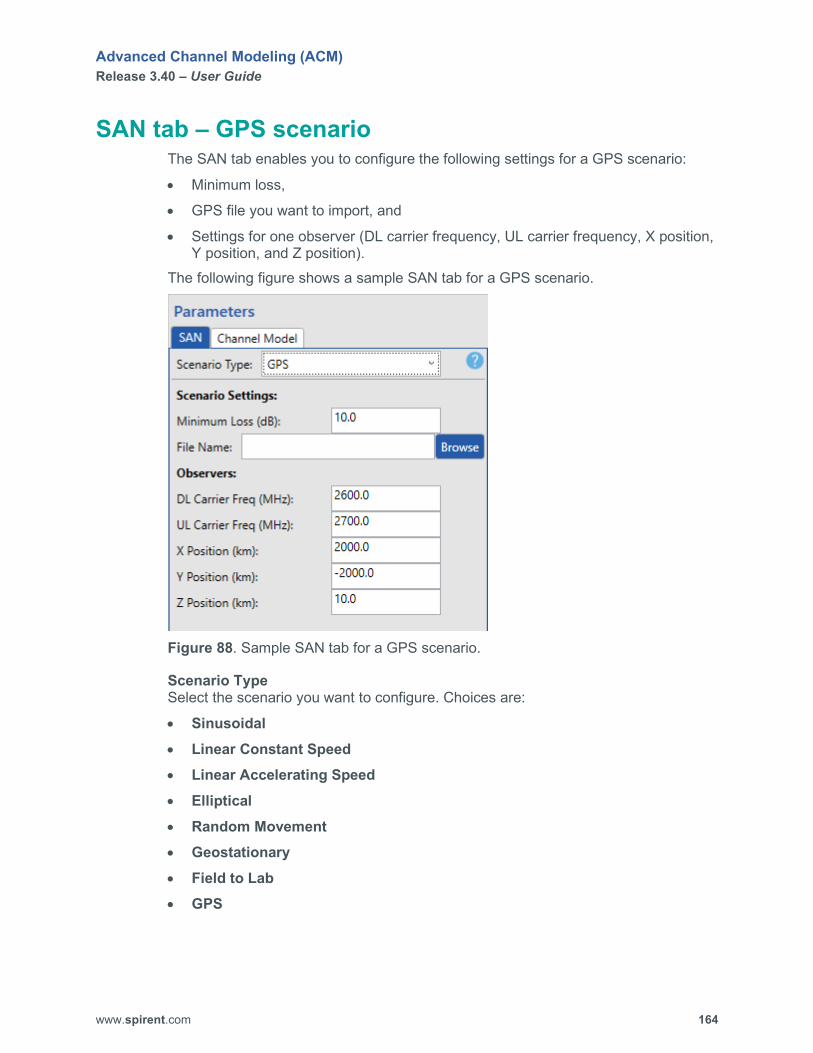
Advanced Channel Modeling (ACM) Release 3.40 – User Guide
www.spirent.com 164
SAN tab – GPS scenario The SAN tab enables you to configure the following settings for a GPS scenario:
• Minimum loss,
• GPS file you want to import, and
• Settings for one observer (DL carrier frequency, UL carrier frequency, X position, Y position, and Z position).
The following figure shows a sample SAN tab for a GPS scenario.
Figure 88. Sample SAN tab for a GPS scenario.
Scenario Type Select the scenario you want to configure. Choices are:
• Sinusoidal • Linear Constant Speed • Linear Accelerating Speed • Elliptical • Random Movement • Geostationary • Field to Lab • GPS

Advanced Channel Modeling (ACM) Release 3.40 – User Guide
www.spirent.com 165
Scenario Settings area Minimum Loss (dB) Specify the minimum loss. Range is 0 to 50 dB. Default is 10.0. File Name Use the Browse button to select the GPS file you want to import.
Observers area DL Carrier Freq (MHz) Specify the downlink carrier frequency for the observer. Range is 30.0 to 5925.0 MHz. Default is 2600.0. UL Carrier Freq (MHz) Specify the uplink carrier frequency for the observer. Range is 30.0 to 5925.0 MHz. Default is 2700.0. X Position (km) Specify the X coordinate of the observer. Range is 0.0 to 100000.0 km. Default is 10000.0. Y Position (km) Specify the Y coordinate of the observer. Range is 0.0 to 100000.0 km. Default is -2000.0. Z Position (km) Specify the Z coordinate of the observer. Range is 0.0 to 100000.0 km. Default is 10.0.
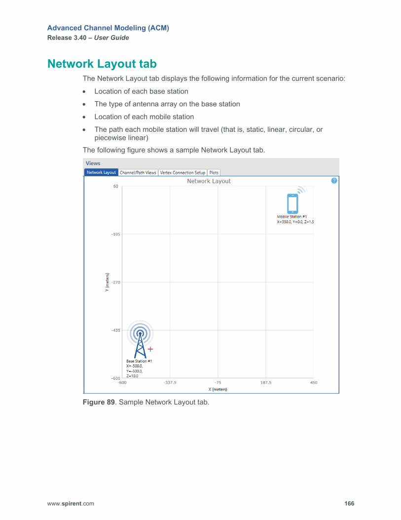
Advanced Channel Modeling (ACM) Release 3.40 – User Guide
www.spirent.com 166
Network Layout tab The Network Layout tab displays the following information for the current scenario:
• Location of each base station
• The type of antenna array on the base station
• Location of each mobile station
• The path each mobile station will travel (that is, static, linear, circular, or piecewise linear)
The following figure shows a sample Network Layout tab.
Figure 89. Sample Network Layout tab.

Advanced Channel Modeling (ACM) Release 3.40 – User Guide
www.spirent.com 167
Channel/Path Views tab The Channel/Path Views tab displays the following information for the selected channel:
• Current settings (for example, channel model, downlink status, uplink status, delay, relative path loss, angle of arrival, and angle of departure)
• A polar graph of the BS (base station) power angle profile (AoD) for each path
• A polar graph of the MS (mobile station) power angle profile (AoA) for each path Using this tab, you can assign and configure the channel model settings for each channel. The following figure shows a sample Channel/Path Views tab.
Figure 90. Sample Channel/Path Views tab.

Advanced Channel Modeling (ACM) Release 3.40 – User Guide
www.spirent.com 168
Channel ID Select the channel you want to configure. Channel Model Specify the model for the selected channel. Choices are SCME UMi, SCME UMa, High Speed Train, CDL-A, CDL-B, CDL-C, CDL-D, CDL-E, Custom, TDL-A, TDL-B, and TDL-C. Default is SCME UMi.
NOTE: In a SAN scenario, only TDL-A, TDL-B, TDL-C, and Custom are supported.
Downlink Enabled? Allows you to enable or disable the downlink for the selected channel. Choices are Yes and No. Default is Yes. Uplink Enabled? Allows you to enable or disable the uplink for the selected channel. Choices are Yes and No. Default is No. Customize button Allows you to create, save, and access a library of custom channel models. To access your custom channel models, click the Customize button, and then click the Load button. Path ID Displays the ID of the path. Enabled? Allows you to enable or disable the associated path. When the path is enabled, it is displayed in the polar graphs at the bottom of the tab. Delay (ns) Specify the delay for the associated path. Range is 0 to 100000 ns. Default is 0 ns. Relative Path Loss (dB) Specify the relative path loss for the associated path. Range is 0 to 32 dB. Default is 0 dB. Midpaths Enabled? Allows you to enable or disable the midpaths for the associated path. AOD (deg) Specify the azimuth (rotation) angle departing the base station for the associated path. Range is -180 to 180 degrees. Default is 6.6 degrees. 0 indicates same as line of sight. AOA (deg) Specify the azimuth (rotation) angle arriving at the mobile station for the associated path. Range is -180 to 180 degrees. Default is 0.7 degrees. 0 indicates same as line of sight. ZOD (deg) Specify the zenith (elevation) angle arriving at the base station for the associated path. Range is 0 to 180 degrees. Default is 90 degrees. 90 indicates same as line of sight.

Advanced Channel Modeling (ACM) Release 3.40 – User Guide
www.spirent.com 169
ZOA (deg) Specify the zenith (elevation) angle arriving at the mobile station for the associated path. Range is 0 to 180 degrees. Default is 90 degrees. 90 indicates same as line of sight. ASD (deg) Specify the azimuth angle spread departure for the associated path. Range is 1 to 75 degrees. Default is 5 degrees. ASA (deg) Specify the azimuth angle spread arrival for the associated path. Range is 1 to 75 degrees. Default is 35 degrees. ZSD (deg) Specify the zenith angle spread departure for the associated path. Range is 0 to 75 degrees. Default is 0 degrees. ZSA (deg) Specify the zenith angle spread arrival for the associated path. Range is 0 to 75 degrees. Default is 0 degrees.
Using TDL Channel Models If you select a TDL channel model, the Channel/Path Views tab displays the following settings:
• path ID
• whether the path is enabled
• delay (ns)
• relative path loss (dB)
• downlink correlation matrix
• uplink correlation matrix
• Doppler spectrum For a TDL channel model, you can load an existing correlation matrix or configure the correlation matrix to one of the following settings using the Correlation Matrix Editor dialog box:
• Uncorrelated
• Calculated
• LTE Low Correlation
• LTE Medium Correlation
• LTE High Correlation
• Custom The Correlation Matrix Editor dialog box appears when you click on a cell in the Correlation Matrix column (Downlink or Uplink).

Advanced Channel Modeling (ACM) Release 3.40 – User Guide
www.spirent.com 170
For a TDL channel model, you can also configure the Doppler Spectrum to one of the following settings:
• Classical The shape of the Classical Doppler spectrum is given by the following equation: S(f) = 1/sqrt(fm^2-f^2) For -fm<f<fm, and 0 otherwise, where fm is the maximum Doppler shift.
• Laplacian The shape of the Laplacian Doppler spectrum is given by the following equation: S(f) = real(1/(sqrt(2)*sigma)*(exp(-sqrt(2)*abs(acos(f/fm)-mu)/sigma)+exp(-sqrt(2)*abs(-acos(f/fm)-mu)/sigma))/sqrt(fm^2-f^2)) For -fm<f<fm, and 0 otherwise, where fm is the maximum Doppler shift, sigma is the angle spread of the Laplacian cluster, and mu is the mean angle of arrival of the cluster.
• Bell The shape of the Bell Doppler spectrum is given by the following equation: S(f) = 1/(1+A*(fmax/f)^2); with A=9, and fmax is 5*fm, and fm is the maximum Doppler shift.
• Half-Bathtub Left The shape of the Half-Bathtub Left Doppler spectrum is given by the following equation: S(f) = 1/sqrt(fm^2-f^2) For -fm<f<0, and 0 otherwise, where fm is the maximum Doppler shift.
• Half-Bathtub Right The shape of the Half-Bathtub Right Doppler spectrum is given by the following equation: S(f) = 1/sqrt(fm^2-f^2) For 0<f<fm, and 0 otherwise, where fm is the maximum Doppler shift.
• Round Top The shape of the Round Top Doppler spectrum is given by the following equation: S(f) = 1-1.720(f/fm)^2+0.785(f/fm)^4 For f<fm, 0 otherwise, where fm is the maximum Doppler shift. The following figure shows what the shape looks like.

Advanced Channel Modeling (ACM) Release 3.40 – User Guide
www.spirent.com 171
Figure 91. Shape of Round Top Doppler spectrum.
The Doppler shape is used for the Stanford University Interim (SUI) channel models. The typical use of SUI channel models is in fixed wireless access.

Advanced Channel Modeling (ACM) Release 3.40 – User Guide
www.spirent.com 172
Vertex Connection Setup tab The Vertex Connection Setup tab enables you to connect to the Vertex channel emulator and select the appropriate topology. The following figure shows a sample Vertex Connection Setup tab.
Figure 92. Sample Vertex Connection Setup tab.
NOTE: In ACM, there is no difference between an 8x4 BiDirectional (TDD) topology and an 8x2 Multi-User (2 Users, DL) BiDirectional (TDD) topology. The geometry sets the correlation between the users, so you do not have to distinguish the multi-user case from the normal case.

Advanced Channel Modeling (ACM) Release 3.40 – User Guide
www.spirent.com 173
OTA Setup tab The OTA Setup tab enables you to specify the method for setting the probe geometry. This tab is only available when the connection type is OTA. The following figure shows a sample OTA Setup tab.
Figure 93. Sample OTA Setup tab.
Method for Setting the Probe Geometry Choices are From Channel Model, From Network Model, and Custom. Default is From Network Model. Attenuate Unused Outputs Creates a phase matrix file for the attenuators with maximum attenuation for the unused outputs. Enable Second Slant Enables you to create scenarios with probes having 2 polarization slants. Polarization Vector (deg) Specify the polarization of each slant.
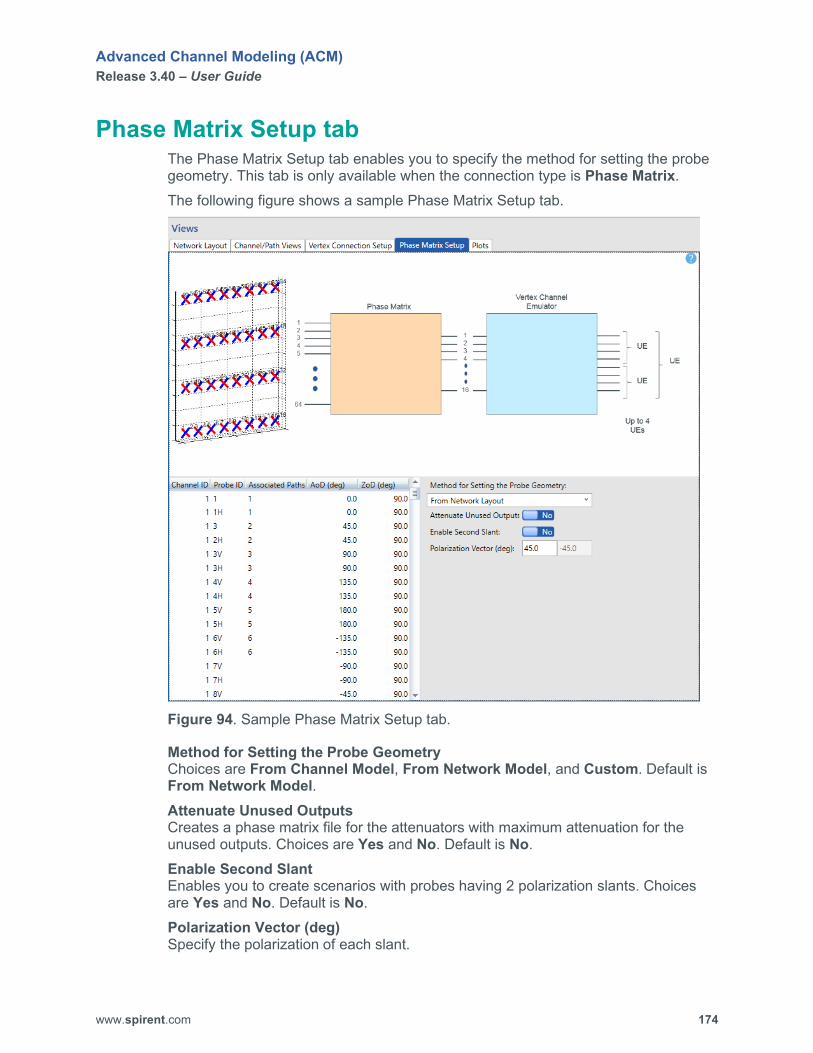
Advanced Channel Modeling (ACM) Release 3.40 – User Guide
www.spirent.com 174
Phase Matrix Setup tab The Phase Matrix Setup tab enables you to specify the method for setting the probe geometry. This tab is only available when the connection type is Phase Matrix. The following figure shows a sample Phase Matrix Setup tab.
Figure 94. Sample Phase Matrix Setup tab.
Method for Setting the Probe Geometry Choices are From Channel Model, From Network Model, and Custom. Default is From Network Model. Attenuate Unused Outputs Creates a phase matrix file for the attenuators with maximum attenuation for the unused outputs. Choices are Yes and No. Default is No. Enable Second Slant Enables you to create scenarios with probes having 2 polarization slants. Choices are Yes and No. Default is No. Polarization Vector (deg) Specify the polarization of each slant.
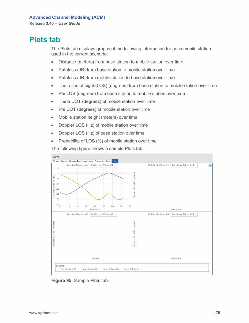
Advanced Channel Modeling (ACM) Release 3.40 – User Guide
www.spirent.com 175
Plots tab The Plots tab displays graphs of the following information for each mobile station used in the current scenario:
• Distance (meters) from base station to mobile station over time
• Pathloss (dB) from base station to mobile station over time
• Pathloss (dB) from mobile station to base station over time
• Theta line of sight (LOS) (degrees) from base station to mobile station over time
• Phi LOS (degrees) from base station to mobile station over time
• Theta DOT (degrees) of mobile station over time
• Phi DOT (degrees) of mobile station over time
• Mobile station height (meters) over time
• Doppler LOS (Hz) of mobile station over time
• Doppler LOS (Hz) of base station over time
• Probability of LOS (%) of mobile station over time The following figure shows a sample Plots tab.
Figure 95. Sample Plots tab.
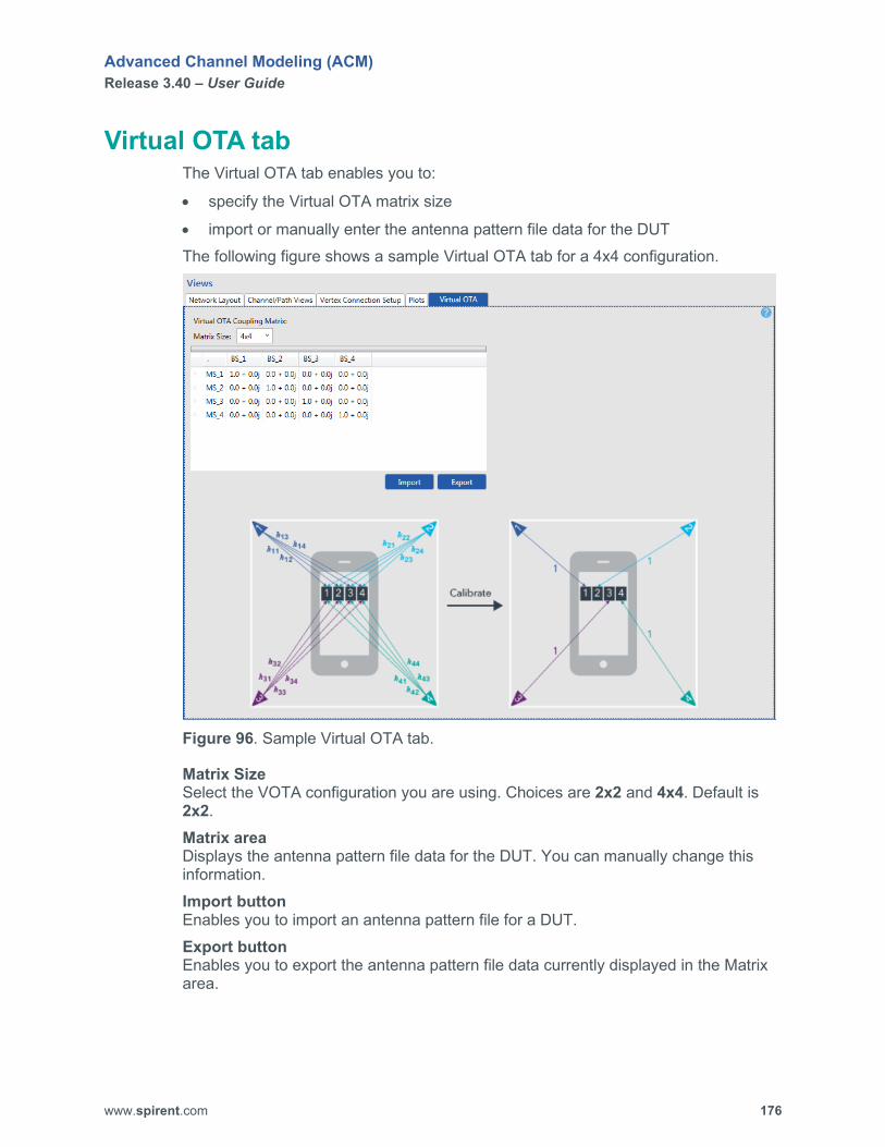
Advanced Channel Modeling (ACM) Release 3.40 – User Guide
www.spirent.com 176
Virtual OTA tab The Virtual OTA tab enables you to:
• specify the Virtual OTA matrix size
• import or manually enter the antenna pattern file data for the DUT The following figure shows a sample Virtual OTA tab for a 4x4 configuration.
Figure 96. Sample Virtual OTA tab.
Matrix Size Select the VOTA configuration you are using. Choices are 2x2 and 4x4. Default is 2x2. Matrix area Displays the antenna pattern file data for the DUT. You can manually change this information. Import button Enables you to import an antenna pattern file for a DUT. Export button Enables you to export the antenna pattern file data currently displayed in the Matrix area.

Advanced Channel Modeling (ACM) Release 3.40 – User Guide
www.spirent.com 177
MIMO OTA Setup tab The MIMO OTA Setup tab enables you to specify the following settings for a MIMO OTA scenario:
• theta tilt
• phi rotation
• tilt/rotate order
• whether to force a rebuild of the PSP
• test volume set level
• mean PSP
• mean PSP at center of test volume This tab also displays the following information for each probe:
• ID
• Set power (analog gain) (dBm)
• Expected power (analog + digital gain) (dBm)
• Fractional power (linear)
• Probe angle phi (deg)
• Probe angle theta (deg)
• Mapping to the port number on the Vertex unit This tab is only available when the connection type is MIMO OTA. The following figure shows a sample MIMO OTA Setup tab.

Advanced Channel Modeling (ACM) Release 3.40 – User Guide
www.spirent.com 178
Figure 97. Sample MIMO OTA Setup tab.
Theta Tilt (deg) Specify the electrical tilt of the antenna pattern. Range is 0.0 to 180.0 degrees. Default is 90.0 degrees. 0.0 indicates no tilt. Phi Rotation (deg) Specify the mechanical rotation of the antenna array. Range is 0.0 to 180.0 degrees. Default is 0. Tilt/Rotate Order Select the order of the virtual tilting and rotation to align the channel model to the probes. Choices are Rotate Then Tilt and Tilt Then Rotate. Default is Rotate Then Tilt. Force Rebuild of PSP Specify whether you want to force a rebuild of the PAS similarity percentage (PSP). Choices are Yes and No. Default is No. Test Volume Set Level (dBm) Specify the volume level. Range is -20.0 to -110.0 dBm. Default is -30.0 dBm.

Advanced Channel Modeling (ACM) Release 3.40 – User Guide
www.spirent.com 179
Mean PSP (%) Specify the mean PAS similarity percentage (PSP). Range is . Default is 0.0.
NOTE: Mean PSP (%) is read-only, and the value displayed is the result from building the scenario.
Mean PSP at Center of Test Volume (%) Specify the mean PAS similarity percentage (PSP) at the center of test volume.
NOTE: Mean PSP at Center of Test Volume (%) is read-only, and the value displayed is the result from building the scenario.
NOTE: The Set Power, Expected Power, and Fractional Power columns are read-only, and the values displayed are the result from building the scenario.

Advanced Channel Modeling (ACM) Release 3.40 – User Guide
www.spirent.com 180
Simulation Builder tab The Simulation Builder tab enables you to specify the settings and generate the IQ playback file for the current scenario file. From this tab, you can also enable the Use Dynamic Level Adjustment setting, which allows you to embed the output level and C/N ratio data in the IQ playback data file when AWGN is enabled for the base station(s) and/or mobile station(s). This feature provides a better digital representation of fading while using Vertex RFM to adjust the overall output level.
NOTE: In Mesh mode, you must set Use Dynamic Level Adjustment to No on the Simulation Builder tab. ACM only supports digital gains at this time for mesh network scenarios.
The Preview button enables you to view plots of the scenario before you build the IQ playback file. The following figure shows a sample Simulation Builder tab.
Figure 98. Sample Simulation Builder tab.
Output File Type Select the type of simulation output file you want to build. Choices are I/Q Data and PHAM Data. Default is I/Q Data. DSPM Type Select the appropriate DSPM type of hardware for the Vertex unit. Choices are DSPM1 10KHz Sampling and DSPM2 30KHz Sampling. Default is DSPM1 10KHz Sampling. Calculate Path Loss? Specify whether you want ACM to calculate path loss. When enabled, path loss is automatically computed and applied to the scenario. When disabled, path loss is not applied. Choices are Yes and No. Default is Yes.
Advanced Channel Modeling (ACM) Release 3.40 – User Guide
www.spirent.com 181
Auto Calculate Simulation Parameters? Specify whether you want ACM to automatically calculate the simulation parameters. When enabled, ACM will automatically determine the optimal parameter settings for the simulation. Choices are Yes and No. Default is Yes.
NOTE: If you are using a piecewise linear motion path, you MUST set Auto Calculate Simulation Parameters? to No. Total Simulation Time (s) Specify the length of the fading segment to be simulated. This is the amount of time that the complete emulation takes. To load the emulation to Vertex, there must be at least 10,000 samples. This parameter is available when Auto Calculate Simulation Parameters? is set to No. Fading Segment Time (s) Specify the amount of time spent in a given location during motion simulation. If you configured a scenario that uses the Static motion type for a mobile station, you must set the Fading Segment Time to a value higher than the minimum value accepted by Vertex. (By default, this is a very small value, and if you selected the Static motion type for a mobile station, the IQ playback file will not have enough samples.) This parameter is available when Auto Calculate Simulation Parameters? is set to No. Up Sampling Factor Specify the divider of the sampling frequency. This is the oversampling ratio to model fading accurately. Typically, the Up Sampling Factor is set to a value between 8 and 32 (where 8 is the largest, and 32 is the smallest). This parameter is available when Auto Calculate Simulation Parameters? is set to No. Select the up sampling factor you want to use. Choices are 8, 16, and 32. Default is 8. Filter Wrap-around? When set to Yes, this setting ensures that there is not discontinuity of the fading waveform between the last sample and the first sample (wraparound point). This discontinuity causes spectral splatter. Fraction of Doppler Frequency Specify the filter cutoff percentage beyond the maximum Doppler frequency fd. (The default is 1.1, meaning 10% beyond fd.). Use Dynamic Level Adjustment Specify whether you want to embed the output level and C/N ratio data in the IQ playback data file when AWGN is enabled for the base station(s) and/or mobile station(s). This feature provides a better digital representation of fading while using Vertex RFM to adjust the overall output level. Choices are Yes and No. Default is No.
NOTE: In Mesh mode, you must set Use Dynamic Level Adjustment to No on the Simulation Builder tab. ACM only supports digital gains at this time for mesh network scenarios.
Advanced Channel Modeling (ACM) Release 3.40 – User Guide
www.spirent.com 182
Dynamic Mode This setting is available when Use Dynamic Level Adjustment is set to Yes. The following Dynamic Mode settings are available:
• Independent: The step attenuator is programmed based on the motion scenario according to the average power change observed.
• Interpolated: The digital gains are modified over time to align with the step attenuator change in order to cancel the step change and reduce the splatter. This requires time alignment, so a timing value – Dynamic Mode Offset – is also available.
Dynamic Mode Offset The + or – time adjustment needed when Dynamic Mode is set to Interpolated. Rotate MS Phi from -180 to +180 Specify whether you want to run the channel model 24 times and virtually rotate the UE each time from -180 degrees to +180 degrees in 15 degree increments. These files are then concatenated into one file. This setting applies to MIMO OTA scenarios and Virtual OTA scenarios. Choices are Yes and No. Default is No. Build Status Displays the current status of the build process. Current Link During simulation building, this represents which base station/mobile station combination is being simulated. Preview button Displays the Plots tab. Build button Starts building the current scenario.

Advanced Channel Modeling (ACM) Release 3.40 – User Guide
www.spirent.com 183
Vertex Player tab The Vertex Player tab enables you to:
• Connect to the Vertex unit.
• Enable Virtual OTA (VOTA) (if you are using the Virtual OTA connection type).
• Apply the VOTA coupling matrix (if you are using the Virtual OTA connection type).
• Download the IQ playback file to the Vertex unit.
• Play/pause the IQ playback file on the Vertex unit. The following figure shows a sample Vertex Player tab.
Figure 99. Sample Vertex Player tab.
Instrument Status Displays the status of the Vertex instrument. Connect button Establishes a connection from ACM to the Vertex unit. File Name Displays the name of the simulation file that was built. Enable Virtual OTA Specify whether you want to enable the Virtual OTA feature. When enabled, ACM will apply the VOTA coupling matrix you specify. Choices are Yes and No. Default is No. Apply OTA Coupling Matrix Enables you to specify the VOTA IQ playback file you want to apply for the Virtual OTA scenario. This parameter is available when Enable Virtual OTA is set to Yes. VOTA Filename Displays the name of the Virtual OTA file you selected.

Advanced Channel Modeling (ACM) Release 3.40 – User Guide
www.spirent.com 184
File Status Displays the status of the simulation file. Download button Downloads the scenario simulation file to the Vertex instrument. Simulation Status Displays the status of the simulation. Play button Plays the simulation file. Stop button Stops playing the simulation file. Pause button Pauses playing the simulation file. Resume button Resumes playing the simulation file.

Advanced Channel Modeling (ACM) Release 3.40 – User Guide
www.spirent.com 185
Simulation Builder Status area Shows the status of the build process. The following figure shows a sample Simulation Builder Status area.
Figure 100. Sample Simulation Builder Status area.

Advanced Channel Modeling (ACM) Release 3.40 – User Guide
www.spirent.com 186
Ribbon toolbar The Ribbon toolbar displays the options for the selected menu at the top of the ACM window. The following figure shows Scenario ribbon toolbar.
Figure 101. Scenario ribbon toolbar.
The following figure shows Configure ribbon toolbar.
Figure 102. Configure ribbon toolbar.
The following figure shows Help ribbon toolbar.
Figure 103. Help ribbon toolbar.

Advanced Channel Modeling (ACM) Release 3.40 – User Guide
www.spirent.com 187
Do you want to save? dialog box Enables you to save the changes you made to the current scenario. The following figure shows a sample Do you want to save? dialog box.
Figure 104. Sample Do you want to save? dialog box.
Save and Continue button Saves the changes you made to the current scenario and then opens a new scenario file. Don’t Save and Continue button Discards the changes you made to the current scenario file since your last save and then opens a new scenario file. Cancel button Closes the dialog box and returns to the current scenario file.

Advanced Channel Modeling (ACM) Release 3.40 – User Guide
www.spirent.com 188
New Scenario/Save Scenario As dialog box Enables you to create a new scenario file or save an existing scenario file as a new scenario file. The following figure shows a sample New Scenario dialog box.
Figure 105. Sample New Scenario dialog box.
The following figure shows a sample Save Scenario As dialog box.
Figure 106. Sample Save Scenario As dialog box.
Name Type the name of the new scenario file. Location Use the Browse button to specify the location where you want to save the new scenario file. By default, scenario files are saved to C:\ProgramData\Spirent Communications\Advanced Channel Modeling\Scenarios. When you click the OK button, the scenario is saved to the location you specify in a folder that has the scenario name you specified in the Name box.

Advanced Channel Modeling (ACM) Release 3.40 – User Guide
www.spirent.com 189
Instrument Configuration dialog box Enables you to select the Vertex instrument(s) and phase shifter you want to use with ACM and specify the IP address of each instrument. The following figure shows a sample Instrument Configuration dialog box.
Figure 107. Sample Instrument Configuration dialog box.
Enabled? Check (enable) the check box of the instrument you want to use. Instrument Name Displays the name of the instrument. IP Address Displays the IP address of the instrument. To change an IP address, click on the IP address, make your changes, and press the ENTER key.

Advanced Channel Modeling (ACM) Release 3.40 – User Guide
www.spirent.com 190
Application Password dialog box Enables you to enter the ACM password you received from Spirent. The following figure shows a sample Application Password dialog box.
Figure 108. Sample Application Password dialog box.
Password Type the ACM password you received from Spirent. HW Key Serial Number Displays the serial number for the ACM USB security key provided by Spirent. The USB security key is required for running ACM.
Pre-build Report dialog box Provides the following information about the scenario before starting the build process:
• the number of down converters required
• the number of up converters required
• the number of DSP modules and Vertex mainframes required at 40 MHz
• the number of DSP modules and Vertex mainframes required at 100 MHz The following figure shows a Pre-build Report dialog box.
Figure 109. Sample Pre-build Report dialog box.

Advanced Channel Modeling (ACM) Release 3.40 – User Guide
www.spirent.com 191
Glossary of Terms ACM Advanced Channel Modeling.
AoA Angle of arrival.
AoD Angle of departure.
ASA Azimuth angle spread arrival.
ASD Azimuth angle spread departure.
BS Base station.
CDL Clustered delay line. Channel model definition in 3GPP TR38.901.
dB Decibel.
DOT Direction of travel.
DS Delay spread.
DSPM type Digital signal processing module. Can be Type 1 (100MHz) or Type 2 (200MHz).
FDD Frequency division duplex.
Advanced Channel Modeling (ACM) Release 3.40 – User Guide
www.spirent.com 192
HST High speed train.
ID Identifier.
I/Q Data In-phase and quadrature phase data. Samples of the radio channel realization in digital domain. Refer to the Vertex channel emulator for data format.
K factor Narrow band K factor is the ratio of Line of Sight component to all non-Line of Sight components.
KB Knowledge Base. The Spirent Knowledge Base contains the latest software and documentation for Spirent products.
LOS Line of sight.
MS Mobile station
NLOS Non-line of sight.
OTA Over the air.
PHAM data Phase and amplitude data. Another file format is I/Q data.
SAN Satellite and aeronautical.
SCME Spatial channel model extended. Three different scenarios are defined: UMi (Urban Micro), UMa (Urban Macro), and SMa (Sub-Urban Macro).
SMa Sub-Urban Macro.

Advanced Channel Modeling (ACM) Release 3.40 – User Guide
www.spirent.com 193
TDD Time division duplex.
TDL Tapped delay line.
TX Transmitter.
UMa Urban Macro.
UMi Urban Micro.
VOTA Virtual over the air.
X,Y,Z Co-ordinates in Cartesian co-ordinate system.
XPR Cross polarization ratio of the radio propagation.
ZoA Zenith of arrival.
ZoD Zenith of departure.
ZSA Angle spread of arrival in zenith.
ZSD Angle spread of departure in zenith.