aerobatics: sport, science, and · pdf fileaerobatics: sport, science, and survival s...
TRANSCRIPT
AEROBATICS: SPORT, SCIENCE, AND SURVIVAL
OTHER TOPIC
S
Aerobatics: Sport, Science, and Survival
Peter F. Bythrow
ince the inception of the airplane as a weapon of warfare, aerobatics has beeninherent to the pursuit of aerial combat. The term itself conjures up the image ofManfred von Richthofen, the Red Baron of the “Flying Circus” squadron, in a Fokkertriplane going head to head with Eddie Rickenbacker of the “Hat in the Ring” squadronin a Spad biplane. Partly because of this archaic image, aerobatics and aerobatic pilotsare often viewed as daredevil and devil-may-care, when for the most part, nothingcould be further from reality. The successfully completed aerobatic maneuver resultsfrom intellectual understanding, detailed planning, and hours of dedicated practice. Itshould not be confused with a bungee jump! This article aims to dispel some of themyths and preconceptions regarding aerobatic flight and the pilots who choose it astheir sport. It will review in part the evolution of competitive sport flying as well asbasic aerobatic maneuvers and their underlying physics. Aerobatic flight regulationsand the application of aerobatic training to routine flight will also be addressed.(Keywords: Aerobatics, International Aerobatic Club, Physics of flight, Sport aviation.)
INTRODUCTIONPerhaps no other athletic endeavor is so demanding
of simultaneous cognitive processing and fine motorskills in a physically grueling and mentally stressfulenvironment as the sport of aerobatics. Few other ath-letes must practice their art while experiencing sus-tained load factors of ±4 to 6 g (1 g = acceleration dueto gravity at the Earth’s surface = 9.8 m/s2). Under theseconditions, the aerobatic pilot who intuitively under-stands the underlying physics of a maneuver can, whenall else is equal, be more adept at its execution than anequally skilled competitor without such intuitiveknowledge. To the combat pilot, understanding anddeftness in aerobatic flight have often meant the dif-ference between life and death. As for nonaerobaticpilots, whose federally mandated initiation into atti-tude excursions is limited to 60° banked turns, they too
JOHNS HOPKINS APL TECHNICAL DIGEST, VOLUME 18, NUMBER 1 (19
can profit from the safety and situational awarenessgained through aerobatic experience. The same holdsfor the airline pilot, whose primary responsibility ispassenger safety.
The ability to maneuver an aircraft in controlledflight about the full range of all three axes (roll, pitch,and yaw) while maintaining complete awareness of one’sdynamic environment is the hallmark of the aerobaticpilot. Skills thus acquired give the pilot the ability andconfidence necessary to address almost any eventualityshort of catastrophic airframe failure. To see how theseskills are developed, this article will discuss the historyof aerobatics, address fundamental maneuvers, and re-view some associated physics. It will also mention Fed-eral Aviation Administration (FAA) regulations and thevalue of aerobatics in recurrent training.
97) 141

P. F. BYTHROW
THE EVOLUTION OF COMPETITIVESPORT FLYING
In World War I as in Desert Storm, the fastest, mostwell-armed, least observable, and most maneuverableaircraft, piloted by the most skilled aviator, survived tofight another day. Most aerobatic maneuvers used todayin civilian training and competition have evolved fromearly fighter tactics. In fact, the Immelmann maneuver,shown in Fig. 1, was named after the World War IGerman ace Max Immelmann. Although credited withits invention, his performance of the maneuver incombat is not confirmed.1
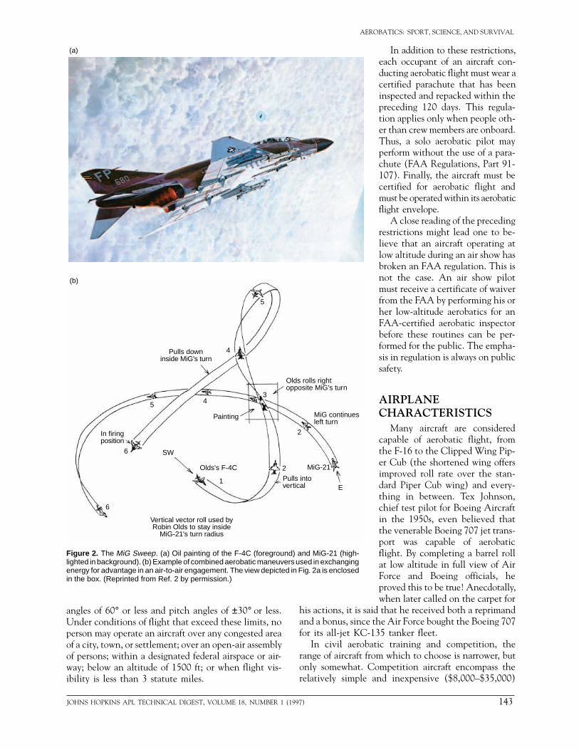
Even though combat aircraft can now sustain super-sonic flight and are equipped with sophisticated air-to-air missiles, history has shown that air-to-air engage-ments seldom occur at supersonic speeds and stillrequire maneuvers similar to those practiced in WorldWar I, World War II, Korea, and Vietnam. Thesecombat maneuvers were and are intended to gain atactical advantage over an opponent and to maximizethe use of the specific characteristics of one’s own air-craft and weapons design. One of the more spectacularaerobatic feats of modern air combat was immortalizedby aviation artist Keith Ferris in MiG Sweep, a portrayalof General Robin Olds’s interception of a MiG-21 inthe skies over North Vietnam.2 In this classic energyfighter (F-4C) versus angles fighter (MiG-21) engage-ment3 (Figs. 2a and 2b), the superior vertical penetra-tion of the F-4C was used in a modified Immelmannand barrel roll maneuver to gain tactical advantageover the MiG-21, despite that aircraft’s superior turningability.
Civilian aerobatic flight has evolved separately fromits antecedent in military air combat maneuvering. It
is seldom performeadversary, but rathor a competitive eit. Today, aerobatiis sponsored by the(EAA) and the Inhome page on the /acro.harvard.edu/I1953, the EAA adstruction of customwitnessed at the anin Oshkosh, Wiscotrolled field at Ostower and is transfo
The IAC was ois now affiliated waerobatic competitments and standarpetition. Tom Pobepion, is the presiaerobatic competitthe IAC. In conjuin, the IAC sponsoin Fond du Lac, W
Today, there arepetition: basic, spounlimited. These cthe maneuver sequthe aircraft to exunlimited categoryseen competing inyou won’t see a Cadvanced or unlim
Figure 1. The Immelmann maneuver, executed by a vertical pull-up to the inverted and a1/2 slow roll to the upright.
142 JOH
d to gain tactical advantage over aner to acquire proficient piloting skillsdge, or often just for the pure joy ofc competition in the United States Experimental Aircraft Associationternational Aerobatic Club (IAC;
World Wide Web is located at http:/AC/iac_homepg.htm). Founded invocates sport aviation and the con--built aircraft. This advocacy is bestnual EAA fly-in held every summernsin. During the event, the uncon-
hkosh acquires a temporary controlrmed into the world’s busiest airport.riginally a separate organization butith the EAA. It supports and fostersion and safety and sets the require-ds of performance for aerobic com-rezny, former world aerobatic cham-
dent of the EAA, and world-classor Linda Hamer is the president ofnction with the Oshkosh EAA fly-rs an annual aerobatic competitionisconsin.
five fundamental categories of com-rtsman, intermediate, advanced, andategories differ in both difficulty ofence and in performance required ofecute the prescribed sequence. An aircraft like the Pitts S2 might be
the basic or sportsman category, butlipped Wing Cub competing in theited category.
REGULATIONSAs one might expect, aerobatic
flight is subject to more restrictiveregulations by the FAA than flightin a less dynamic aerial environ-ment. These regulations are de-signed primarily to protect the pub-lic at large from injury or loss dueto the pursuit of sport aviation.The secondary reason for these reg-ulations is to protect the pilot andpassengers of the aerobatic aircraft.
The FAA defines aerobatics as“an intentional maneuver involv-ing an abrupt change in an air-craft’s attitude, an abnormal atti-tude, or abnormal acceleration notnecessary for normal flight” (FAARegulations, Part 91-103). Thedefinition of normal attitude isgenerally considered to mean bank
NS HOPKINS APL TECHNICAL DIGEST, VOLUME 18, NUMBER 1 (1997)
AEROBATICS: SPORT, SCIENCE, AND SURVIVAL
angles of 60° or less and pitch angles of ±30° or less.Under conditions of flight that exceed these limits, noperson may operate an aircraft over any congested areaof a city, town, or settlement; over an open-air assemblyof persons; within a designated federal airspace or air-way; below an altitude of 1500 ft; or when flight vis-ibility is less than 3 statute miles.
5
4
45
6
6
1
2
3
2
E
SW
Pulls downinside MiG's turn
Painting
Olds rolls rightopposite MiG's turn
MiG continuesleft turn
MiG-21
Pulls intovertical
Olds's F-4C
In firingposition
Vertical vector roll used byRobin Olds to stay inside
MiG-21's turn radius
(a)
(b)
Figure 2. The MiG Sweep. (a) Oil painting of the F-4C (foreground) and MiG-21 (high-lighted in background). (b) Example of combined aerobatic maneuvers used in exchangingenergy for advantage in an air-to-air engagement. The view depicted in Fig. 2a is enclosedin the box. (Reprinted from Ref. 2 by permission.)
his actions, it is saidand a bonus, since thfor its all-jet KC-13
In civil aerobatirange of aircraft fromonly somewhat. Corelatively simple an
JOHNS HOPKINS APL TECHNICAL DIGEST, VOLUME 18, NUMBER 1 (19
In addition to these restrictions,each occupant of an aircraft con-ducting aerobatic flight must wear acertified parachute that has beeninspected and repacked within thepreceding 120 days. This regula-tion applies only when people oth-er than crew members are onboard.Thus, a solo aerobatic pilot mayperform without the use of a para-chute (FAA Regulations, Part 91-107). Finally, the aircraft must becertified for aerobatic flight andmust be operated within its aerobaticflight envelope.
A close reading of the precedingrestrictions might lead one to be-lieve that an aircraft operating atlow altitude during an air show hasbroken an FAA regulation. This isnot the case. An air show pilotmust receive a certificate of waiverfrom the FAA by performing his orher low-altitude aerobatics for anFAA-certified aerobatic inspectorbefore these routines can be per-formed for the public. The empha-sis in regulation is always on publicsafety.
AIRPLANECHARACTERISTICS
Many aircraft are consideredcapable of aerobatic flight, fromthe F-16 to the Clipped Wing Pip-er Cub (the shortened wing offersimproved roll rate over the stan-dard Piper Cub wing) and every-thing in between. Tex Johnson,chief test pilot for Boeing Aircraftin the 1950s, even believed thatthe venerable Boeing 707 jet trans-port was capable of aerobaticflight. By completing a barrel rollat low altitude in full view of AirForce and Boeing officials, heproved this to be true! Anecdotally,when later called on the carpet for that he received both a reprimande Air Force bought the Boeing 7075 tanker fleet.c training and competition, the which to choose is narrower, but
mpetition aircraft encompass thed inexpensive ($8,000–$35,000)
97) 143
P. F. BYTHROW
such as the Bellanca/American Champion Citabria(airbatic spelled backwards) to the Unlimited ClassExtra 300 ($250,000–$500,000). Figure 3 shows theauthor in a midrange ($45,000–$100,000) Bellanca/American Champion Decathlon.
The designation of an aerobatic aircraft is funda-mentally a function of structural load factors and powerplant features (inverted fuel and oil systems, etc.). Allof the aircraft cited here have at least one thing incommon: Beyond the limit load factor, the aircraft maysustain damage, and beyond about 1.5 times that limit,the aircraft will experience structural failure and thepilot will experience distress. All aircraft designated asaerobatic are designed with minimum structural loadfactors of +6 and –3 g, but many are designed for loadfactors in excess of ±10 g.
BASIC AEROBATICSAerobatic routines performed in training or compe-
tition generally consist of a sequence of maneuvers thatare drawn directly from or are modifications of the basicaerobatic building blocks, i.e., the loop, the slow roll,the barrel roll, the spin, and the snap roll. Nearly allother aerobatic maneuvers, except perhaps the “Lom-cevak”4 (a torque-coupled poststall maneuver named forthe shudder one experiences after taking a stiff drink;possibly devised by an inebriated Czech contestant onthe evening before the 1962 world championships), arecombinations or modifications of these five maneuvers.
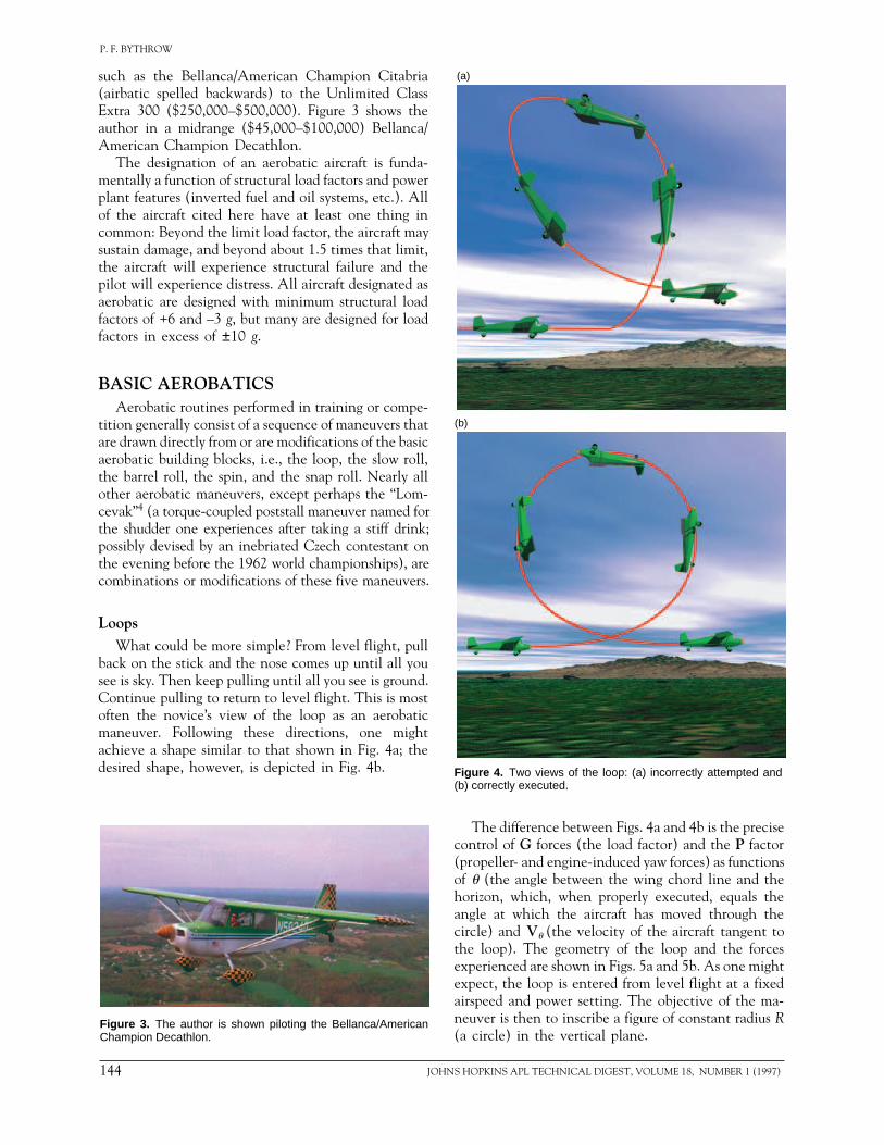
LoopsWhat could be more simple? From level flight, pull
back on the stick and the nose comes up until all yousee is sky. Then keep pulling until all you see is ground.Continue pulling to return to level flight. This is mostoften the novice’s view of the loop as an aerobaticmaneuver. Following these directions, one mightachieve a shape similar to that shown in Fig. 4a; thedesired shape, however, is depicted in Fig. 4b.
Figure 3. The author is shown piloting the Bellanca/AmericanChampion Decathlon.
144 JOH
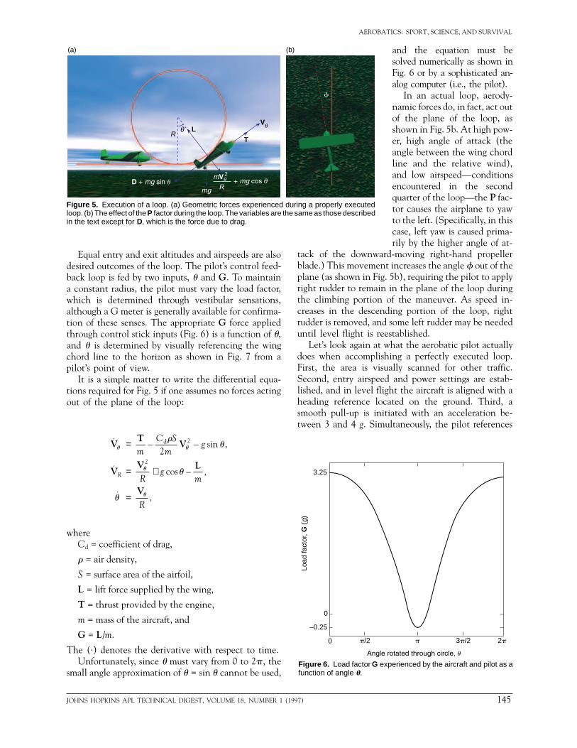
The difference between Figs. 4a and 4b is the precisecontrol of G forces (the load factor) and the P factor(propeller- and engine-induced yaw forces) as functionsof u (the angle between the wing chord line and thehorizon, which, when properly executed, equals theangle at which the aircraft has moved through thecircle) and Vu (the velocity of the aircraft tangent tothe loop). The geometry of the loop and the forcesexperienced are shown in Figs. 5a and 5b. As one mightexpect, the loop is entered from level flight at a fixedairspeed and power setting. The objective of the ma-neuver is then to inscribe a figure of constant radius R(a circle) in the vertical plane.
Figure 4. Two views of the loop: (a) incorrectly attempted and(b) correctly executed.
(a)
(b)
NS HOPKINS APL TECHNICAL DIGEST, VOLUME 18, NUMBER 1 (1997)
AEROBATICS: SPORT, SCIENCE, AND SURVIVAL
Equal entry and exit altitudes and airspeeds are alsodesired outcomes of the loop. The pilot’s control feed-back loop is fed by two inputs, u and G. To maintaina constant radius, the pilot must vary the load factor,which is determined through vestibular sensations,although a G meter is generally available for confirma-tion of these senses. The appropriate G force appliedthrough control stick inputs (Fig. 6) is a function of u,and u is determined by visually referencing the wingchord line to the horizon as shown in Fig. 7 from apilot’s point of view.
It is a simple matter to write the differential equa-tions required for Fig. 5 if one assumes no forces actingout of the plane of the loop:
˙ – – sin ,
˙ cos –
˙
dVT
V
VV L
V
u u
u
u
ru
u
u
=
= +
=
mC S
mg
Rg
m,
R,
R
22
2
whereCd = coefficient of drag,
r = air density,
S = surface area of the airfoil,
L = lift force supplied by the wing,
T = thrust provided by the engine,
m = mass of the aircraft, and
G = L/m.
The (·) denotes the derivative with respect to time.Unfortunately, since u must vary from 0 to 2p, the
small angle approximation of u = sin u cannot be used,
tack of the downwarblade.) This movemenplane (as shown in Fig.right rudder to remainthe climbing portion creases in the descendrudder is removed, anduntil level flight is ree
Let’s look again at wdoes when accomplishFirst, the area is visuSecond, entry airspeedlished, and in level fligheading reference locsmooth pull-up is inittween 3 and 4 g. Simu
Figure 5. Execution of a loop. (a) Geometric forces experienced during a properly executedloop. (b) The effect of the P factor during the loop. The variables are the same as those describedin the text except for D, which is the force due to drag.
Figure 6. Load factor G exfunction of angle u.
3.25
0
–0.25
Load
fact
or, G
(g)
0 p/2
RL
Tθ
mg R
f
(a) (b)
2
JOHNS HOPKINS APL TECHNICAL DIGEST, VOLUME 18, NUMBER
and the equation must besolved numerically as shown inFig. 6 or by a sophisticated an-alog computer (i.e., the pilot).
In an actual loop, aerody-namic forces do, in fact, act outof the plane of the loop, asshown in Fig. 5b. At high pow-er, high angle of attack (theangle between the wing chordline and the relative wind),and low airspeed—conditionsencountered in the secondquarter of the loop—the P fac-tor causes the airplane to yawto the left. (Specifically, in thiscase, left yaw is caused prima-rily by the higher angle of at-
d-moving right-hand propellert increases the angle f out of the 5b), requiring the pilot to apply in the plane of the loop duringof the maneuver. As speed in-ing portion of the loop, right
some left rudder may be neededstablished.hat the aerobatic pilot actuallying a perfectly executed loop.ally scanned for other traffic. and power settings are estab-ht the aircraft is aligned with aated on the ground. Third, aiated with an acceleration be-ltaneously, the pilot references
perienced by the aircraft and pilot as a
2p3p/2p
1 (1997) 145
P. F. BYTHROW
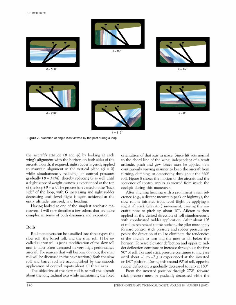
Figure 7. Variation of angle u as viewed by the pilot during a loop.
the aircraft’s attitude (u and f) by looking at eachwing’s alignment with the horizon on both sides of theaircraft. Fourth, if required, right rudder is gently appliedto maintain alignment in the vertical plane (f = 0)while simultaneously reducing aft control pressuresgradually (u = 3p/4), thereby reducing G as well untila slight sense of weightlessness is experienced at the topof the loop (u = p). The process is reversed on the “backside” of the loop, with G increasing and right rudderdecreasing until level flight is again achieved at theentry altitude, airspeed, and heading.
Having looked at one of the simplest aerobatic ma-neuvers, I will now describe a few others that are morecomplex in terms of both dynamics and execution.
Rolls
Roll maneuvers can be classified into three types: theslow roll, the barrel roll, and the snap roll. (The so-called aileron roll is just a modification of the slow rolland is most often executed in very high performanceaircraft. For reasons that will become obvious, the snaproll will be discussed in the next section.) Both the slowroll and barrel roll are accomplished by the smoothapplication of control inputs about all three axes.
The objective of the slow roll is to roll the aircraftabout the longitudinal axis while maintaining the fixed
146 JOH
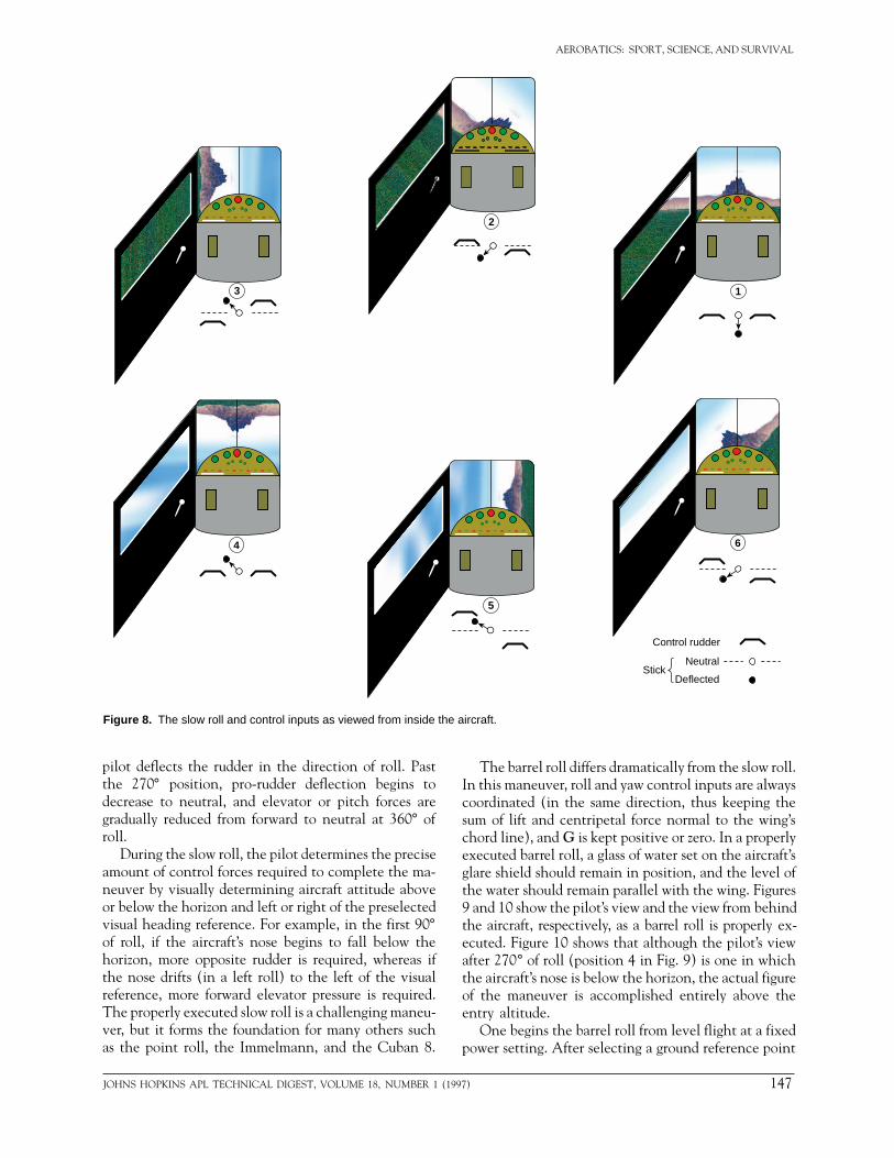
orientation of that axis in space. Since lift acts normalto the chord line of the wing, independent of aircraftattitude, pitch and yaw forces must be applied in acontinuously varying manner to keep the aircraft fromturning, climbing, or descending throughout the 360°roll. Figure 8 shows the motion of the aircraft and thesequence of control inputs as viewed from inside thecockpit during this maneuver.
After aligning heading with a prominent visual ref-erence (e.g., a distant mountain peak or highway), theslow roll is initiated from level flight by applying aslight aft stick (elevator) movement, causing the air-craft’s nose to pitch up about 10°. Aileron is thenapplied in the desired direction of roll simultaneouslywith coordinated rudder application. After about 10°of roll as referenced to the horizon, the pilot must applyforward control stick pressure and rudder pressure op-posite the direction of roll to eliminate the tendenciesof the aircraft to turn and the nose to fall below thehorizon. Forward elevator deflection and opposite rud-der deflection continue to increase throughout the first90° of roll. Forward stick pressure continues to increaseuntil about –1 to –2 g is experienced at the invertedor 180° position. During this second 90° of roll, oppositerudder deflection is gradually decreased to zero at 180°.
From the inverted position through 270°, forwardstick pressure must be gradually decreased while the
NS HOPKINS APL TECHNICAL DIGEST, VOLUME 18, NUMBER 1 (1997)
AEROBATICS: SPORT, SCIENCE, AND SURVIVAL
Figure 8. The slow roll and control inputs as viewed from inside the aircraft.
1
2
3
4
5
6
Control rudder
Neutral
DeflectedStick
pilot deflects the rudder in the direction of roll. Pastthe 270° position, pro-rudder deflection begins todecrease to neutral, and elevator or pitch forces aregradually reduced from forward to neutral at 360° ofroll.
During the slow roll, the pilot determines the preciseamount of control forces required to complete the ma-neuver by visually determining aircraft attitude aboveor below the horizon and left or right of the preselectedvisual heading reference. For example, in the first 90°of roll, if the aircraft’s nose begins to fall below thehorizon, more opposite rudder is required, whereas ifthe nose drifts (in a left roll) to the left of the visualreference, more forward elevator pressure is required.The properly executed slow roll is a challenging maneu-ver, but it forms the foundation for many others suchas the point roll, the Immelmann, and the Cuban 8.
JOHNS HOPKINS APL TECHNICAL DIGEST, VOLUME 18, NUMBER 1 (1
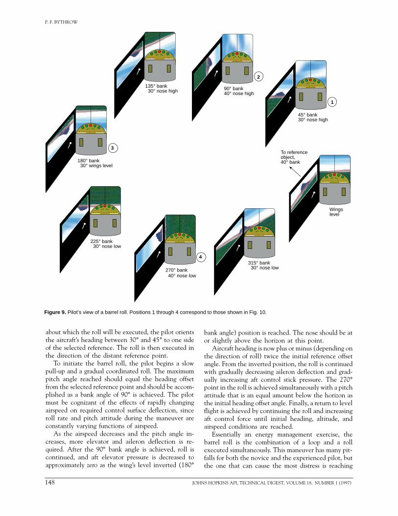
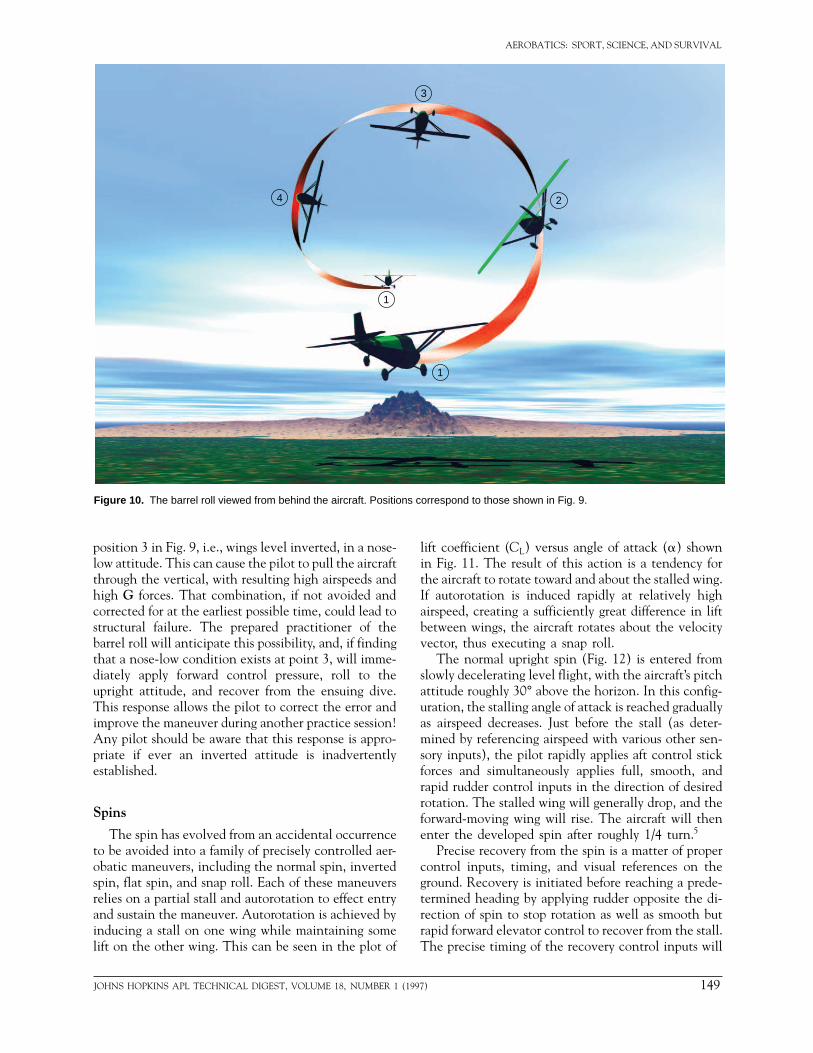
The barrel roll differs dramatically from the slow roll.In this maneuver, roll and yaw control inputs are alwayscoordinated (in the same direction, thus keeping thesum of lift and centripetal force normal to the wing’schord line), and G is kept positive or zero. In a properlyexecuted barrel roll, a glass of water set on the aircraft’sglare shield should remain in position, and the level ofthe water should remain parallel with the wing. Figures9 and 10 show the pilot’s view and the view from behindthe aircraft, respectively, as a barrel roll is properly ex-ecuted. Figure 10 shows that although the pilot’s viewafter 270° of roll (position 4 in Fig. 9) is one in whichthe aircraft’s nose is below the horizon, the actual figureof the maneuver is accomplished entirely above theentry altitude.
One begins the barrel roll from level flight at a fixedpower setting. After selecting a ground reference point
997) 147
P. F. BYTHROW
135° bank 30° nose high 90° bank
40° nose high
45° bank30° nose high
315° bank 30° nose low270° bank
225° bank 30° nose low
180° bank 30° wings level
Wingslevel
To referenceobject,40° bank
1
2
3
4
40° nose low
Figure 9. Pilot’s view of a barrel roll. Positions 1 through 4 correspond to those shown in Fig. 10.
about which the roll will be executed, the pilot orientsthe aircraft’s heading between 30° and 45° to one sideof the selected reference. The roll is then executed inthe direction of the distant reference point.
To initiate the barrel roll, the pilot begins a slowpull-up and a gradual coordinated roll. The maximumpitch angle reached should equal the heading offsetfrom the selected reference point and should be accom-plished as a bank angle of 90° is achieved. The pilotmust be cognizant of the effects of rapidly changingairspeed on required control surface deflection, sinceroll rate and pitch attitude during the maneuver areconstantly varying functions of airspeed.
As the airspeed decreases and the pitch angle in-creases, more elevator and aileron deflection is re-quired. After the 90° bank angle is achieved, roll iscontinued, and aft elevator pressure is decreased toapproximately zero as the wing’s level inverted (180°
148 JOH
bank angle) position is reached. The nose should be ator slightly above the horizon at this point.
Aircraft heading is now plus or minus (depending onthe direction of roll) twice the initial reference offsetangle. From the inverted position, the roll is continuedwith gradually decreasing aileron deflection and grad-ually increasing aft control stick pressure. The 270°point in the roll is achieved simultaneously with a pitchattitude that is an equal amount below the horizon asthe initial heading offset angle. Finally, a return to levelflight is achieved by continuing the roll and increasingaft control force until initial heading, altitude, andairspeed conditions are reached.
Essentially an energy management exercise, thebarrel roll is the combination of a loop and a rollexecuted simultaneously. This maneuver has many pit-falls for both the novice and the experienced pilot, butthe one that can cause the most distress is reaching
NS HOPKINS APL TECHNICAL DIGEST, VOLUME 18, NUMBER 1 (1997)
AEROBATICS: SPORT, SCIENCE, AND SURVIVAL
1
2
3
4
1
Figure 10. The barrel roll viewed from behind the aircraft. Positions correspond to those shown in Fig. 9.
position 3 in Fig. 9, i.e., wings level inverted, in a nose-low attitude. This can cause the pilot to pull the aircraftthrough the vertical, with resulting high airspeeds andhigh G forces. That combination, if not avoided andcorrected for at the earliest possible time, could lead tostructural failure. The prepared practitioner of thebarrel roll will anticipate this possibility, and, if findingthat a nose-low condition exists at point 3, will imme-diately apply forward control pressure, roll to theupright attitude, and recover from the ensuing dive.This response allows the pilot to correct the error andimprove the maneuver during another practice session!Any pilot should be aware that this response is appro-priate if ever an inverted attitude is inadvertentlyestablished.
Spins
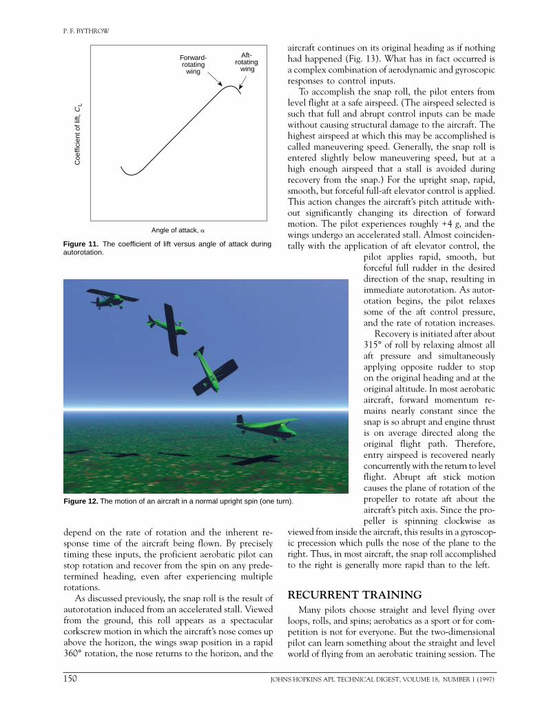
The spin has evolved from an accidental occurrenceto be avoided into a family of precisely controlled aer-obatic maneuvers, including the normal spin, invertedspin, flat spin, and snap roll. Each of these maneuversrelies on a partial stall and autorotation to effect entryand sustain the maneuver. Autorotation is achieved byinducing a stall on one wing while maintaining somelift on the other wing. This can be seen in the plot of
JOHNS HOPKINS APL TECHNICAL DIGEST, VOLUME 18, NUMBER 1 (19
lift coefficient (CL) versus angle of attack (a) shownin Fig. 11. The result of this action is a tendency forthe aircraft to rotate toward and about the stalled wing.If autorotation is induced rapidly at relatively highairspeed, creating a sufficiently great difference in liftbetween wings, the aircraft rotates about the velocityvector, thus executing a snap roll.
The normal upright spin (Fig. 12) is entered fromslowly decelerating level flight, with the aircraft’s pitchattitude roughly 30° above the horizon. In this config-uration, the stalling angle of attack is reached graduallyas airspeed decreases. Just before the stall (as deter-mined by referencing airspeed with various other sen-sory inputs), the pilot rapidly applies aft control stickforces and simultaneously applies full, smooth, andrapid rudder control inputs in the direction of desiredrotation. The stalled wing will generally drop, and theforward-moving wing will rise. The aircraft will thenenter the developed spin after roughly 1/4 turn.5
Precise recovery from the spin is a matter of propercontrol inputs, timing, and visual references on theground. Recovery is initiated before reaching a prede-termined heading by applying rudder opposite the di-rection of spin to stop rotation as well as smooth butrapid forward elevator control to recover from the stall.The precise timing of the recovery control inputs will
97) 149
P. F. BYTHROW
depend on the rate of rotation and the inherent re-sponse time of the aircraft being flown. By preciselytiming these inputs, the proficient aerobatic pilot canstop rotation and recover from the spin on any prede-termined heading, even after experiencing multiplerotations.
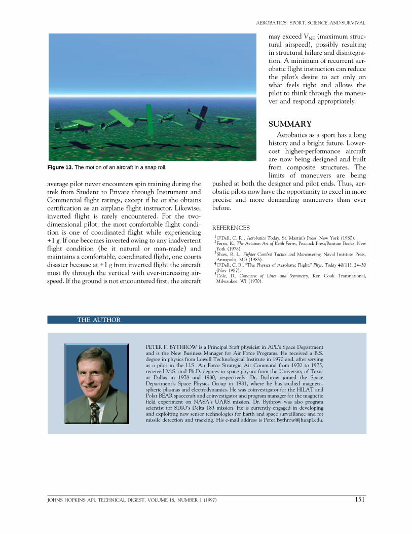
As discussed previously, the snap roll is the result ofautorotation induced from an accelerated stall. Viewedfrom the ground, this roll appears as a spectacularcorkscrew motion in which the aircraft’s nose comes upabove the horizon, the wings swap position in a rapid360° rotation, the nose returns to the horizon, and the
aircraft continues had happened (Fia complex combinresponses to cont
To accomplish level flight at a sasuch that full andwithout causing sthighest airspeed acalled maneuverinentered slightly bhigh enough airsprecovery from thesmooth, but forcefThis action changout significantly motion. The pilotwings undergo an tally with the app
viewed from insideic precession whicright. Thus, in moto the right is gen
RECURRENTMany pilots ch
loops, rolls, and sppetition is not forpilot can learn somworld of flying fro
Aft-rotating wing
Forward-rotating
wingC
oeffi
cien
t of l
ift, C
L
Angle of attack, a
Figure 11. The coefficient of lift versus angle of attack duringautorotation.
Figure 12. The motion of an aircraft in a normal upright spin (one turn).
150 JOH
on its original heading as if nothingg. 13). What has in fact occurred isation of aerodynamic and gyroscopicrol inputs.the snap roll, the pilot enters from
fe airspeed. (The airspeed selected is abrupt control inputs can be madeructural damage to the aircraft. Thet which this may be accomplished isg speed. Generally, the snap roll iselow maneuvering speed, but at aeed that a stall is avoided during
snap.) For the upright snap, rapid,ul full-aft elevator control is applied.es the aircraft’s pitch attitude with-changing its direction of forward experiences roughly +4 g, and theaccelerated stall. Almost coinciden-lication of aft elevator control, the
pilot applies rapid, smooth, butforceful full rudder in the desireddirection of the snap, resulting inimmediate autorotation. As autor-otation begins, the pilot relaxessome of the aft control pressure,and the rate of rotation increases.
Recovery is initiated after about315° of roll by relaxing almost allaft pressure and simultaneouslyapplying opposite rudder to stopon the original heading and at theoriginal altitude. In most aerobaticaircraft, forward momentum re-mains nearly constant since thesnap is so abrupt and engine thrustis on average directed along theoriginal flight path. Therefore,entry airspeed is recovered nearlyconcurrently with the return to levelflight. Abrupt aft stick motioncauses the plane of rotation of thepropeller to rotate aft about theaircraft’s pitch axis. Since the pro-peller is spinning clockwise as
the aircraft, this results in a gyroscop-h pulls the nose of the plane to thest aircraft, the snap roll accomplishederally more rapid than to the left.
TRAININGoose straight and level flying overins; aerobatics as a sport or for com- everyone. But the two-dimensional
ething about the straight and levelm an aerobatic training session. The
NS HOPKINS APL TECHNICAL DIGEST, VOLUME 18, NUMBER 1 (1997)
ROBATICS: SPORT, SCIENCE, AND SURVIVAL
AEFigure 13. The motion of an aircraft in a snap roll.
average pilot never encounters spin training during thetrek from Student to Private through Instrument andCommercial flight ratings, except if he or she obtainscertification as an airplane flight instructor. Likewise,inverted flight is rarely encountered. For the two-dimensional pilot, the most comfortable flight condi-tion is one of coordinated flight while experiencing+1 g. If one becomes inverted owing to any inadvertentflight condition (be it natural or man-made) andmaintains a comfortable, coordinated flight, one courtsdisaster because at +1 g from inverted flight the aircraftmust fly through the vertical with ever-increasing air-speed. If the ground is not encountered first, the aircraft
pushed at both thobatic pilots now hprecise and morebefore.
REFERENCES1O’Dell, C. R., Aerobati2Ferris, K., The Aviation York (1978).
3Shaw, R. L., Fighter CoAnnapolis, MD (1985)
4O’Dell, C. R., “The Ph(Nov 1987).
5Cole, D., Conquest oMilwaukee, WI (1970).
JOHNS HOPKINS APL TECHNICAL DIGEST, VOLUME 18, NUMBER 1 (19
may exceed VNE (maximum struc-tural airspeed), possibly resultingin structural failure and disintegra-tion. A minimum of recurrent aer-obatic flight instruction can reducethe pilot’s desire to act only onwhat feels right and allows thepilot to think through the maneu-ver and respond appropriately.
SUMMARYAerobatics as a sport has a long
history and a bright future. Lower-cost higher-performance aircraftare now being designed and builtfrom composite structures. Thelimits of maneuvers are being
e designer and pilot ends. Thus, aer-ave the opportunity to excel in more demanding maneuvers than ever
cs Today, St. Martin’s Press, New York (1980).Art of Keith Ferris, Peacock Press/Bantam Books, New
mbat Tactics and Maneuvering, Naval Institute Press,.ysics of Aerobatic Flight,” Phys. Today 40(11), 24–30
f Lines and Symmetry, Ken Cook Transnational,
THE AUTHOR
PETER F. BYTHROW is a Principal Staff physicist in APL’s Space Departmentand is the New Business Manager for Air Force Programs. He received a B.S.degree in physics from Lowell Technological Institute in 1970 and, after servingas a pilot in the U.S. Air Force Strategic Air Command from 1970 to 1975,received M.S. and Ph.D. degrees in space physics from the University of Texasat Dallas in 1978 and 1980, respectively. Dr. Bythrow joined the SpaceDepartment’s Space Physics Group in 1981, where he has studied magneto-spheric plasmas and electrodynamics. He was coinvestigator for the HILAT andPolar BEAR spacecraft and coinvestigator and program manager for the magneticfield experiment on NASA’s UARS mission. Dr. Bythrow was also programscientist for SDIO’s Delta 183 mission. He is currently engaged in developingand exploiting new sensor technologies for Earth and space surveillance and formissile detection and tracking. His e-mail address is [email protected].
97) 151