aiaa 2002-3602 ssme
TRANSCRIPT

AIAA 2002-3602
Propellant Densification for Shuttle: The SSME Perspective
William D. Greene and Dayna L. Boxx
NASA Marshall Space Flight Center, Huntsville, AL
Abstract
The subject of cryogenic propellant densification as a potential upgrade to the Space Shuttle is a
subject that has been raised on several occasions over the last decade. Due to advancements in
densification technology made as a part of and in parallel to the X-33 project, the subject was
raised and studied once again in May 2001. Across the Space Shuttle program people from
many disciplines converged to discuss issues and perform trade studies to determine whether
densified propellants was worth pursuing. This paper discusses one of these areas, specifically
the Space Shuttle Main Engine (SSME). The effects of propellant densification on steady state
performance are presented along with discussions of potential transient performance issues.
Engine component redesign and retrofit issues are discussed as well the high level requirements
to modify the ground test stands to accommodate propellant densification hardware and tanks.
And finally, the matter of programmatic concerns enters the subject at band as part of a
discussion of SSME recertification requirements. In the end, potential benefits to SSME
performance can be demonstrated and, subject to the densification scheme chosen, there does not
appear to insurmountable technical obstacles.
Nomenclature
Symbols
Isp Specific impulse
rh Mass flow rate
AP Pressure drop
P Fluid density
R Flow resistance
R Degrees Rankine
/a Viscosity
Acron ¥ms
DLH2 Densified LH2
DLO2 Densified LO2
Copyright © 2002 by the American Institute of Aeronautics
and Astronautics, Inc. No copyright is asserted under Title
17, U.S. Code. The U.S. Government has a royalty-free
license to exercise all rights under the copyright claimed
herein for Governmental Purlx)ses. All other rights are
reserved by the copyright owner.
ETT
HPFP
HPFF
HPOP
HPOT
ITT
LH2
LN2
LO2
LPFP
LPOP
MR
NBS
RLV
ROM
SSME
SSTO
TSH
External to tank densification
High pressure fuel pump
High pressure fuel turbine
High pressure oxidizer pump
High pressure oxidizer turbine
Internal to tank densification
Liquid hydrogen
Liquid nitrogen
Liquid oxygen
Low pressure fuel pump
Low pressure oxidizer pump
Mixture ratio
National Bureau of Standards
Reusable Launch Vehicle
Rough order of magnitude
Space Shuttle Main Engine
Single Stage to Orbit
Thermodynamic SuppressionHead

Background
The concept of utilizing propellant
densification within the Space Shuttle
program is not an entirely novel proposition.
In 1994, M.M. Fazah of NASA Marshall
Space Flight Center [1] published an extensive
report on the matter in which he examined
propellant densification concepts, Shuttle
infrastructure impacts, and ultimate potential
payload gains. The conclusion of this report
was that while payload gains were likely
realizable, the cost of development and
implementation was not justified by these
gains.
Since the time of the Fazah report, a great deal
of research and development work was
undertaken in the area of propellant
densification. References [2] through [7]
represent a partial listing of published reports
on the progress of this work most of which
was funded under the auspices of the X-33
program and the single-stage-to-orbit
Reusable Launch Vehicle (SSTO-RLV)
studies. Further, this work was undertaken at
different times and to differing degrees by
Boeing, Lockheed Martin, NASA Glenn
Research Center, and NASA Marshall Space
Flight Center. Thus, continuing interest in the
subject of propellant densification developed abroad base.
With the cancellation of the X-33 and SSTO-
RLV programs in 2000, those working in the
field of propellant densification were left with
a great deal of developed technology but
potentially no immediate application to a
specific vehicle. This is how and when the
subject arose of reexamining the utilization of
propellant densification on the Space Shuttle.
In May 2001, a study was initiated to
determine whether propellant densification
was a viable potential upgrade to the Space
Shuttle program. The broader results of this
study will likely be reported elsewhere but itcan be stated that the final conclusion was
similar to the one made in 1994: it has
potential, but even with the advances made,
this potential does not justify the expense.
This report is focused on one particular aspect
of the May 2001 study, the impacts and effects
of densified propellants on the Space Shuttle
Main Engine (SSME) program. That such a
degree of specialization is possible bears
testimony to the level of effort and manpower
dedicated to the overall study.
In fact, it was likely due to this level of effort
and due to the advancement in propellant
densification technology that the finalconclusions were inevitable. From a broad
philosophical or conceptual level, the case for
propellant densification is undeniable. Butwhen forced to examine the details of both the
existing system infrastructure that is to be
retrofit and the requirements of a successful
propellant densification process, the case
becomes substantially more clouded. If the
devil is in the details, then surely the devil is
made of money.
Steady State Performance Adjustments
In evaluating the steady state performance of
the SSME utilizing densified propellants it is
necessary to first consider the global effects of
colder, denser propellants on the system. The
first global effect arises from the fact that in
addition to being colder, densified propellants
carry less energy available for eventualcombustion.
As a first-order approximation to account for
this effect of lower propellant available
energies, an adiabatic frozen-flame analysis
was conducted. Figure 1 shows the results for
variations in both liquid hydrogen (LH2) and
liquid oxygen (LO2) temperature. The y-axis
in these plots is the percentage change in

m
E
I,-
,#c
c
=-o
002
001
0
-0.01
-0 02
-003
-0.04
-0.05
-0.06
-12 - 10 -8 -6 -4 -2 0 2
Change In LH2 Temperature (R)
E
m
E
,#
c
=-¢.)
0.1
0,05
0
-0.05
-0,1
-015
-0.2
-0.25
-0.3
-50 *40 -30 -20 -10 0 10
Change In LO2 Temperature (R)
Figure 1. The Estimated Change in Adiabatic Flame Temperature Due to Propellant
Densification of Both LH2 and LO2
adiabatic flame temperature. The
corresponding change in system performance,
specifically the combustion chamber
characteristic velocity is proportional to the
square root of this deficit in flame temperature
[8]. Later, when the SSME Power Balance is
used to analyze the engine cycle, these
changes to the combustion performance will
be incorporated.
The next global consideration is that of system
resistances. The typical practice is to assign to
various engine components fixed flow
resistances or, in the case of throttling valves,
fixed position versus resistance curves. Thus,
the fluid pressure drops through the engine
circuit become exclusively a function of fluid
velocity and fluid density. The pressure drop
equation takes the form as follows:
m2R_p - (1)
p
Where: AP = pressure drop
vh = mass flow
R = flow resistance
p = flow density
With a little algebraic manipulation one finds
that for a fixed geometry, this resistance factor
is directly proportional to the standard fluid
dynamics friction factor. Over the typical
range of mainstage operation points, assumingthat this flow resistance is fixed is a
reasonably good assumption.

Figure 2.
cM
e_
_c
gc
1,,1
2O
16
12
8
4
0
-50 -40 -30 -20 -10
Change In LO2 Temperature (R)
Approximate Change in Main Injector LO2 Flow Resistance with Densification
However, with the introduction of densified
propellants, this assumption is weakened due
to changes in propellant viscosity, particularlyLO2.
Rather than attempt to track down every flow
resistance within a steady state model of the
SSME, for a first order approximation only
those components with the largest pressure
drops, the true system drivers, are examined.
Due to the relatively small changes in LH2
viscosity over the range of temperatures under
consideration, there is no component on the
fuel side of the engine worthy of any effort.
On the oxidizer side of the engine, however,
one component stands out, the main injector.
The two preburner injectors are fed by
throttling control valves so any changes in
pressure drop there can be overcome with
valve position changes. But the main injector
has no such compensating control factor
directly upstream.
Using the 1911 Blasius approximation for
friction factor for simplicity [9], and factoring
out elements of fixed geometry and fixed
overall mass flowrate (i.e., engine power level
control point), the following relationship canbe derived:
/ &l/4
Rdens =l/'_noml
R .ore \/Z_,., )(2)
Where: R dens = flOW resistance, densified
R horn = flow resistance, nominal
/.zj_.._= viscosity, densified
/_,o,, = viscosity, nominal
Figure 2 shows the results for this simple
calculation using standard National Bureau of
Standards (NBS) properties for LO2. It
should be noted that there have been
suggestions that LO2 viscosity changes are, in
reality, more dramatic than reported by the
NBS tables particularly in region below
approximately 125R. Without a fullcharacterization of this effect, however, it will
not be considered here. Further, as will be
discussed, it is difficult to justify the need for
LO2 densification much below liquid nitrogen
(LN2) temperatures around 140R.
Densification Combinations
Probably one of the most interesting trades to
be performed when considering propellantcombinations for a launch vehicle is the issue
of the engine mixture ratio. Engine
performance and durability are traded main

Figure3.
8
-- 7
5
3
22
" 1
& o
_ -1
-2
28 30 32 34
LH2 Temperature (R)
Densification of Liquid Hydrogen
36 38
10
6
2
go
8-2
120 130 140 150 160 170
LO2 Tern perature (R)
Figure 4. Densification of Liquid Oxygen
propulsion system, tanking, and trajectory
requirements. However, such trades are most
appropriate for a new vehicle system. In the
case of densification for the Space Shuttle,
retrofitting the existing hardware for the new
propellant properties becomes necessary.
With no flexibility on the side of
recommending significant flight hardware
modifications, a ground rule for this study, the
whole issue of deciding upon a mixture ratio
becomes simplified.
Further, there is little drive within the SSME
community to consider mixture ratios
significantly higher than the current nominal
value. Higher engine mixture ratios translate
to higher combustion temperatures throughout
the engine and consequently lower life and
reliability estimates. Also, higher engine
mixture ratios also mean lower performance
(i.e., specific impulse). For these reasons,

only mixtureratiosator belowthecurrentnominalvalueareconsidered.
And finally, the lastpiecein thepuzzlecomesfrom densificationtechnologyitself. Theability to subcoolthebulk temperatureof alargevolumeof cryogenicliquid within aflight-weight tank is not withoutphysicallimitations. Thetypical magnitudeof theambientheatleakinto non-vacuumjacketedtanksmeansthatit is neverpossibleto achieveabulk densificationequalto thatof theground-basedpropellantdensificationequipment.This effectis mostdramaticwithLH2 dueto thegreaterheattransferareaandthelower total loadedLH2 mass,whichresultsin relativelyhigherheatleaksin thosetanks. While thefinal bulk averagetemperatureof LH2 is dependentuponthedetailsof thedensificationsystem,valuesof29Rto 3IR arereasonableestimatesfor thecurrentstate-of-the-art.
Figure3 showsthedegreeof densificationachievedatthisbulk averagetemperatureofLH2 comparedto thecurrentnominalLH2temperature.Using30Rasanoptimisticbutreasonableestimatefor thebulk averagetemperature,onefinds thatthedensityof LH2is increasedby slightlymorethan5%. Thismeansthatwithin thegivenvolumeof theSpaceShuttleLH2 tank,5%moreLH2 canbeloaded.Thus,in orderto maintainamixtureratioequalto thecurrentmixtureratio,LO2would haveto alsobedensifiedby 5%.
Figure4 showsasimilar plot of thedensitychangein LO2 with densification.Usingthevalueof just over5%densification,onefindsthattheappropriateLO2 temperatureinapproximately140R.This temperatureiscoincidentallyandconvenientlyjust aboutthenormalboiling point temperaturefor liquidnitrogen(LN2), a fluid oftenusedin thedensificationprocess.
Thus,thetwo extremesfor consideringenginemixture ratiocomefrom thefollowingpropellantcombinations:
• BothLH2 andLO2 densifiedto 30Rand140Rrespectfully. Mixture ratio equaltothenominalvalueof 6.032.
• LH2 densifiedto 30RbutLO2 unchanged.Mixture ratio reducedto approximately5.75.
Obviously,therearean infinite numberofintermediatepointsbetweenthesetwo valuesbut for thepurposesof this examination,thesetwo extremeswill beconsidered.
Steady State Power Balance Results
Using the Rocketdyne SSME Power Balance
and the various input adjustments and
propellant combinations derived above, the
effects of propellant densification on various
engine parameters can be examined. Figure 5
contains five plots summarizing many of the
significant engine parameter changes.
The first changes to consider are the overall
engine performance changes. When going to
densified propellants but maintaining the same
mixture ratio, the only effect is a slight
suppression of the combustion efficiency
resulting in a slight decrease in specific
impulse (Isp). However, the thrust level
remains essentially unchanged. If only LH2densification is considered with the resultant
decreased in mixture ratio, the Isp increases
but the thrust level decreases. While the
general wisdom of rocketry is that higher Isp
is almost always good, there may be some
trajectory circumstances, including abortscenario considerations, where this thrust
change could be significant. This would be anarea of further research should the Space
Shuttle Program ever decide to go forward
with densified propellants.

Theparametersin theotherthreeplotscontainedwithin Figure5 pertainto internalengineparameters:pumpdischargepressures,turbinedischargetemperatures,andturbopumpspeeds.Theseparametersdescribetherobustnessof theengine. In themoststraightforwardsense,the lessstresseson thehardware--lowerpressures,temperatures,andspeeds--thegreaterthestatisticalreliability.Consideringthehistoryof theSSME,probablythemostcritical parameteris thehighpressureturbinedischargetemperatures.It canbeseenthateitherscenarioactstoreducethesevalueswith thereductionbeingespeciallyhigh in thecaseof thedensifiedLH2 at amixture ratioof 5.75. Theonlyparameterthat showsanincreaseacrossallthreeplots in thehighpressurefuel pump(HPFP)dischargepressurefor thedensifiedLH2 case.This is dueto thegreatermassflow for the5.75mixture ratiooffsettingthedecreasein volumedueto densification.However,this increaseis quitesmallcomparedto theotherreliability gainswithinthesystem.
Theestimationof reliability valuesis alwaysanimpreciseactivity. AttemptsweremadeduringtheMay 2001studyto quantify thereliability gainsfrom theparameterchangesillustratedin Figure5. However,theresultsfrom theseeffortswereinconclusive.Thatleavesonly thequalitativeargumentsaspresentedhere. It is sufficientto saythattheuseof densifiedpropellantswithin theSSMEholdsthepotentialfor increasingreliabilitydueto reductionsin systemstressparameters.
Transient Performance Issues
A detailed analysis of SSME transient
performance, engine start, shutdown, and
throttling, was not performed as part of the
May 2001 examination of densified
propellants for Space Shuttle. It would have
been accomplished if the project had reached a
sufficient maturity level, but the project was
shelved before it got that far.
However, a discussion of potential issues was
assembled [10] with the primary focus being
engine start. A significant issue with the
Block 2 SSME is the generation of
temperature spikes in the two preburners
during the start transient [11]. A great deal of
work has been done to modify the SSME start
sequence to minimize as much as possible the
generation of these spikes, thereby ensuring
greater life for the high pressure turbines. The
densification of LO2 has the potential for
making these spikes worse.
The SSME ignition sequence is based upon
using the LO2 already within the engine at the
time of engine start command. By controlling
the temperature of this LO2, and therefore the
density, it is possible to influence how much
LO2 initially gets into the two preburners.
Too much too soon and the result is high
temperature spikes. Too little too late and the
result is a failure to light or, possibly, a
detonation event. Thus, deviations in either
direction from the delicate balance currently
achieved during SSME start have the potential
of damaging hardware.
It would not be impossible to achieve this
same balance with densified LO2, but what is
envisioned is the need for a higher degree of
active control. The conditions achieved today
are extremely repeatable but largely obtained
passively. In order to maintain these
conditions, and thus ensure reliable and
smooth ignition with colder LO2 temperatures
at the engine inlet, more work is required.
One suggestion would be to incorporate a two
position, high/low, chilldown bleed system.
By controlling the rate at which ambient heat
leak into the engine is rejected, it may be
possible to get back to today's internal engine
conditions at start. Such a system, while

15
10
O5
00
60
40
20
0
-20
-40
-60
-80
-100
-120
-0 5
EngineSpecificImpulse
IL
DLH2 DLH2 and DLO2
MR=5 75 MR=6 032
Pump DischargePressures
DLH2
MR=5 75
oHPFP
BHPOP
oPBP
DLH2 and OLO2
M R=6032
0
-500
-100o
-1500
-2000
-2500
-3000
EngineVacuumThrust
DLH2 E)LH2 and DLO2
MR=5 15 MR=6 032
o
-20
-40
-60
+8o
*1oo
High PressureTurbine Discharge o.PFT
_ Temperatures °.POT
DLH2 DLH2 and DLO2
MR=5 75 MR=6 032
o
.2oo
.4oo
.8oo
-8oo
1ooo
.12oo
oLPFTP
rlHPFTP
II LPOTP
BHPOTP
OLH2 DLH2 and OLO2
MR=5 75 MR=6 032
TurbomachinerySpeeds
Figure 5. Steady State Effects of Propellant Densification on SSME Parameters
conceptually simple, would require extensive
testing and retrofit of engine and facility
equipment (test site and launch site).
At first glance there does not appear to be any
issues with densified LH2 and the start
sequence. It has even been suggested that the
colder, denser LH2 would act to further
minimize the ignition temperature spikes in
the preburners [10], but such a benefit could
only be verified by testing.
The final subject that falls roughly within the
bounds of engine transient performance
considerations is that of combustion stability.
This, even more than engine start and
shutdown, is an area lacking in detailed
research to date. Again, the primary concernis the densified LO2.
The Block 2 SSME, unlike the original SSME,
has no obvious combustion instability
suppression devices in the main combustion
chamber. The original SSME, and those
launched for about fifteen years, had built-in

acoustic cavities and main injector baffles.
Through analysis and extensive testing, it was
decided that these devices were not necessary
as the engine was sequentially upgraded to the
final point of the Block 2 design. Thus, if an
instability mode should become a possibility
with densified propellants, today's SSME
stands unprotected.
The concern is centered upon the jet breakup,
atomization, and mixing of densified LO2 as
compared to normal boiling point LO2. The
densified LO2 would be slower moving and
heavier as it was injected into the chamber.Because the LH2 enters the main combustion
chamber primarily in the form of a hot gas,
there is little concern with regard to its
changes in character, but the LO2 behavior
remains something of an unknown.
It is possible that this concern in unfounded.Several tests with subcooled LO2 were
conducted on the NASA Marshall Space
Flight Center Technology Test Bed in the
mid-90s. The engine inlet LO2 temperatures
used for these tests were 15R to 20R higher
than those being proposed here (i.e., at normal
boiling point LN2 temperatures) and the
SSME tested was of the older design with the
instability suppression devices, but these tests
were conducted safely with no apparent
stability issues arising. Nevertheless, this
remains an area requiring further research if
densified propellants were ever truly
implemented on the Space Shuttle program.
Component Redesign or Retrofit
Other than the potential hardware changes
mentioned above (a two-stage chilldown bleed
on the LO2 side and possibly combustion
stability accoutrements) the only other
obvious hardware change necessary to the
SSME in order to use densified propellants is
the application of insulation to prevent liquidair formation. Such insulation already exists
on the LH2 side of the engine, but if densified
LO2 is to be used then the LO2 side must be
similarly outfitted. Whether this insulation
would be required throughout the LO2 system
or only on the colder, low-pressure portions
would likely remain an issue to discover
during development testing.
Another potential trouble area that would
require a thorough examination through
testing would be cavitation regimes the SSME
low pressure fuel pump. While one of the
benefits attributed to propellant densification
is the lowering of fluid vapor pressures,
thereby theoretically increasing margins to
incipient cavitation, some concern has been
expressed regarding reductions to the factor of
Thermodynamic Suppression Head (TSH)
(see [12], pg. 53-55 for discussion of TSH).
The combined effect of lower vapor pressure
and lower TSH may lead to a situation where
there are no gains whatsoever in terms of
actual engine operation capabilities due to the
need to maintain adequate margins.
Engine Recertification
Assuming that the detailed technical issues
resulting from the use of densified propellants
on SSME can be overcome, there remain
larger and more expensive programmaticissues to consider. The two most significant
of these issues would be the need to recertify
the SSME fleet for flight and making the
necessary changes to the engine ground test
stands to incorporate propellant densification.
Because the transition to densified propellants
would be such a fundamental change to the
SSME environments, as part of the May 2001
study and in coordination with the NASA
SSME Project Office, it was determined that a
standard Class A certification program would
be necessary prior to the first flight. It was
assumed under such a program the pre-
certification development testing would be

similar to pastprogramsandincludetwoenginescoveringroughlyforty groundtests.Theactualcertificationtestserieswouldconsistof two engines,different from thedevelopmentengines,andit toowould spanjust overforty tests.Forthepurposesofplanning,thedetailsof thesetestsarenotespeciallyimportantbut thesetestsaredesignedto coverabroadspectrumofconditionsto ensuresafeengineoperation.
In concretetermsof makingaroughorderofmagnitude(ROM) costestimate,it wasassumedthattwo of thefour enginesrequiredto completethedevelopmentandcertificationprogramcouldbeassembledfrom existingparts. Theothertwoengineswould likelycomefrom theflight fleet andwouldhavetobereplacedwith newhardware.Thus,thebillfor accomplishingthis testingwould includetwo SSMEsandroughlyeightygroundtests.Basedupon2001dollars,theROM costforthis bill comesto approximately$160million.
Note thatthis valueis only for certificationoftheexistingSSMEdesign. If significantmodificationsarenecessaryto thedesign,thentheentirefleetof flight engineswouldhavetoberetrofittedwith thenewhardware(assuminga simpleretrofit waspossible)andtherewould likely bearequirementto conductacceptancetestsfor eachengineanew. Thiswould tackat leastanother$15 million ontothetestcosts.
Test Stand and Launch Site Modifications
What the above ROM costs do not include are
the modifications necessary to the ground test
facilities needed to generate the vast quantities
of densified propellants that would be required
to conduct the testing. A detailed discussion
of densified propellant production will not be
presented here (see [1] through [7]) but a
quick overview is in order.
For the purposes here, there are two methods
of turning normal boiling point cryogenic
propellants into sub-cooled, densifed
propellants: internal to tank (ITT) and external
to tank (ETT). In both cases, the idea is
prepare the propellants prior to test. Currently
there does not exist a technology capable of
densifying propellants fast enough to support
an engine firing real time.
ITT densification is depicted in a very simple
schematic in Figure 6. Here, sub-cooling is
achieved by reducing the tank pressure
causing the fluid to boil and release heat until
it reaches equilibrium. ETT densification,
depicted in Figure 7, is accomplished by either
transferring propellants from one tank to
another through a densification unit or by
recirculating fluid through a densification unit
with a pump. The densification unit itself
could use a variety of densification methods
the most common of which is the use of sub-
cooled cryogenic baths and heat exchangers.
The situation for SSME becomes a bit more
complex due to the current setup at the NASA
Stennis Space Center in Mississippi where
SSME ground tests are conducted. For a
typical, full duration ground test, propellants
are supplied not only from the tanks located
on the test stand, but also from barges located
next to the test stand. Without propellant
transfer from these barges, the ground test
program could not fulfill the requirement of
simulating flight-like mission durations on thetest stand.
There are several possible solutions to
overcome this complexity but all of them
require significant facility modification:
Densify both the stand run tanks and the
barges in place. The problem with this
solution is that it would require multiple
densification systems and it is not clear
that the barge fleet could be modified
10

Facility
propellanttank Vacuum pump or
steam ejector
Figure 6. Simple Sketch of Internal to Tank (1TT) Propellant Densification
Densified
propellanttank
Propellantdensification unit
Normal
Boiling Point
propellanttank
Facility
propellanttank
Propellantdensification unit
Figure 7. Simple Sketch of External to Tank (ETT) Propellant Densification Schemes
sufficiently to perform effective densification.
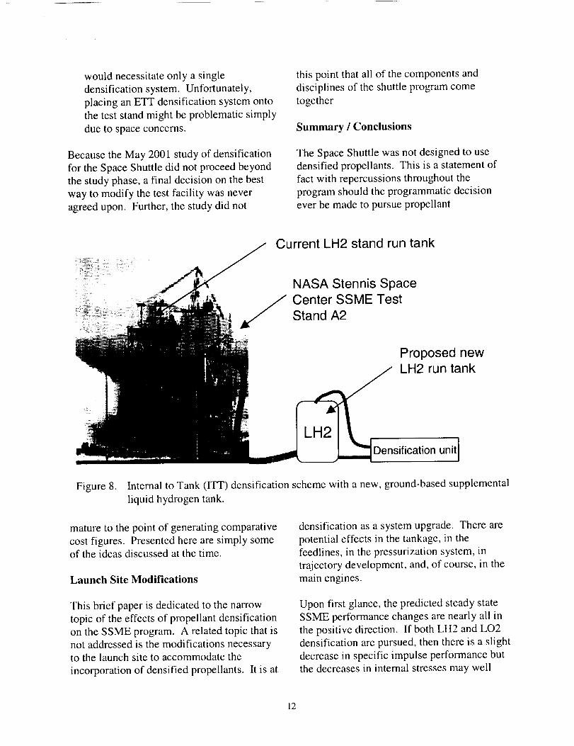
• Add supplemental, ground-based tanks to
replace the barges. In this scenario, the
propellant from the barges would be off-loaded to these new tanks and densified
there. This would eliminate the problems
with adapting the barges for densification
but not the requirement for a separate
densification system for the stand tanks.
The exception to this would be if the
supplemental tanks were large enough sothat the stand tanks were redundant and
could be back-filled with densified
propellants immediately prior to test
initiation. An illustration of such a system
with ETT densification is shown in Figure8.
Replace the test stand tanks. This is the
most straightforward choice but might be
the most expensive. It would eliminate the
necessity for propellant transfer in-run and
11
would necessitate only a single
densification system. Unfortunately,
placing an ETT densification system onto
the test stand might be problematic simply
due to space concerns.
Because the May 2001 study of densification
for the Space Shuttle did not proceed beyond
the study phase, a final decision on the best
way to modify the test facility was never
agreed upon. Further, the study did not
this point that all of the components and
disciplines of the shuttle program come
together
Summary / Conclusions
The Space Shuttle was not designed to use
densified propellants. This is a statement of
fact with repercussions throughout the
program should the programmatic decision
ever be made to pursue propellant
Current LH2 stand run tank
NASA Stennis SpaceCenter SSME Test
Stand A2
Proposed newLH2 run tank
Densification unitI
Figure 8. Internal to Tank (ITT) densification scheme with a new, ground-based supplemental
liquid hydrogen tank.
mature to the point of generating comparative
cost figures. Presented here are simply some
of the ideas discussed at the time.
Launch Site Modifications
densification as a system upgrade. There are
potential effects in the tankage, in the
feedlines, in the pressurization system, in
trajectory development, and, of course, in the
main engines.
This brief paper is dedicated to the narrow
topic of the effects of propellant densification
on the SSME program. A related topic that is
not addressed is the modifications necessary
to the launch site to accommodate the
incorporation of densified propellants. It is at
Upon first glance, the predicted steady state
SSME performance changes are nearly all in
the positive direction. If both LH2 and LO2
densification are pursued, then there is a slight
decrease in specific impulse performance but
the decreases in internal stresses may well
12

outweigh this factor. For the case of LH2densification alone combined with the
subsequent change to lower vehicle mixture
ratio, there is actually an increase in specific
impulse performance to be coupled with the
decreases in internal component
environments. From the standpoint of steady
state performance alone, a pretty good case
can be made that propellant densification for
SSME has several advantages.
However, there may be a more difficult task to
undertake in the realm of transient
performance. To date, not a great deal of
work has been dedicated to this subject, but it
would appear that a chilldown procedure
different than that used today would be
necessary to ensure repeatable, benign engine
starts. Potential fixes, such as a two-position
relief system, likely would require
modifications to both the engine and the
facility (test and launch). Also, substantial
development testing would have to be
dedicated to this subject.
Other things that would have to be ironed out
through development testing include an
exploration of cavitation margins of the low
pressure fuel pump with colder propellants
and altered thermodynamic suppression headcharacteristics. If LO2 densification is
pursued then the issue of combustion stabilityhas to be addressed as well as increased
insulation requirements for the LO2 system.
How the SSME test stands are to be modified
to accommodate all of this necessary testing
raises the specter of significant investments in
new facility tanks and densification systems.
And finally, should all of these factors be
overcome and the SSME and the Space
Shuttle program become prepared to accept
densified propellants, the expense of SSME
recertification rises as a potential obstacle.
While this is primarily a technical discussion,
it is hard to ignore a requirement in the rangeof hundreds of millions of dollars.
Thus, the conclusion of this brief discussion,
and that of the May 2001 study, is that there
may be some benefits to the use of densified
propellants within the SSME and that the most
of the potential technical issues can likely be
overcome. This suggests that for future
launch vehicles propellant densification
should be seriously considered as a baseline
element of thereby reaping the benefits while
avoiding the issues of retrofit and
recertification. On the Space Shuttle program,
howver, whether these benefits justify the
time, effort, and cost is another question. For
the time being the answer to that question
remains no.
Acknowledgements
The authors would like to sincerely thank
David Coote, Matt Marsh, and David Wilson
for their valuable input to this paper.
References
i. Fazah, M. M., "STS Propellant
Densification Feasibility Study" (NASA
Technical Memorandum 108467)
. Lak T., Lozano, M., and Tomsik, T.,
"Advancement in Cryogenic Propulsion
System Performance through Propellant
Densification" (AIAA-96-3123)
, Tomsik, T., "Performance Tests of a
Liquid Hydrogen Propellant
Densification Ground System for the
X33/RLV" (NASA Technical
Memorandum 107469, AIAA-97-2976)
, Greene, W. and Vaughan, D.,
"Simulation and Testing of In-Tank
Propellant Densification For LaunchVehicles," AIAA-98-3688.
13

.
.
,
.
.
10.
11.
12.
Anthony, M. and Greene, W.,
"Analytical Model of an Existing
Propellant Densification Unit Heat
Exchanger," AIAA-98-3689.
Greene, W., Knowles, T. and Tomsik,
T., "Propellant Densification for Launch
Vehicles: Simulation and Testing 1999,"
AIAA-99-2335
Jurns, J., Tomsik, T. and Greene, W.,
"Testing of Densified Liquid HydrogenStratification in a Scale Model
Propellant Tank" (1999 Cryogenic
Engineering and International Cryogenic
Materials Conference, Montr6al,
Qu6bec, Canada, and NASA Technical
Memorandum 2001-209391)
Hill, P. and Peterson, C. Mechanics and
Thermodynamics of Propulsion
(Addison-Wesley Publishing Co., 1965).
White, F. Fluid Mechanics (McGraw-
Hill, Inc., 1979).
Bradley, T. "Block II SSME Start Issues
with Densified Propellants"
(presentation by Boeing Rocketdyne to
the Space Shuttle Propulsion System
Integration Group, May 2001).
Greene, W.D. "Estimation Method for
Block 2 SSME Preburner Ignition
Temperature Spikes," AIAA-2001-3539.
Sobin, A.J. and Bissell, W.R.,
"Turbopump Systems for Liquid Rocket
Engines," NASA SP-8107, Aug. 1974
14