aidan singh report
DESCRIPTION
Report on maintainingTRANSCRIPT

A
PRACTICAL TRAINING
REPORT
ON
“MANUFACTURING OF DI PIPES AND MECH.
MAINTANANCE SDP 2”
AT
JINDAL SAW LTD, MUNDRA
Submitted in partial fulfilment for the award of the degree of
BACHELOR OF TECHNOLOGY
IN
MECHANICAL ENGINEERING
GUIDED BY: SUBMITTED BY:Mr. Akhilesh jaguari Mr. Aidan singhAsst. Prof. (M.E.) B.Tech (M.E.) VII SEMJIT, Jaipur (2011-15) 11EJJME002
RAJASTHAN TECHNICAL UNIVERSITY, KOTA DEPARTMENT OF CIVIL ENGINEERING
JAIPUR INSTITUTE OF TECHNOLOGY, Group of Institution, Jaipur
JIT/DOCE/2014-15/PS 01
RAJASTHAN TECHNICAL UNIVERSITY, KOTA
DEPARTMENT OF CIVIL ENGINEERING
JAIPUR INSTITUTE OF TECHNOLOGY, GROUP OF
INSTITUTION, JAIPUR
CERTIFICATE
This is to certify that the Practical Training Seminar report for Practical
Training taken at JINDAL SAW LTD.(IPU) , MUNDRA (GUJRAT)
from 11th June 2014 to 10th July 2014 is submitted by Mr. AIDAN
SINGH (11EJJME002) in partial fulfillment for the award of degree of
Bachelor of Technology in Mech. Engineering has been found
satisfactory and is approved for submission.
Mr. Anil kumar sharama Mr. Akhilesh jaguari(Project Coordinator) (Guide)Chief proctor Assistant ProfessorDeptt. of Mech. Engineering Deptt. of Mech. EngineeringJIT, Jaipur JIT, Jaipur
ACKNOWLEDGEMENT
JIT/DOCE/2014-15/PS 02

This is to acknowledge my gratitude towards my guide Mr. Akhilesh jagauri Asst.
Professor dept. of Mech. Engineering for his guidance and suggestions in preparing
this seminar report. Her suggestions and way of summarizing the things make me to
go for independent studying and trying my best to get the maximum in my topic this
made my circle of knowledge vary vast. I am highly thankful for this seminar.
I also express my profound sense of gratitude to Mr. Anil kumar sharma (H.O.D.
Mech.) giving encouragement and opportunity to complete my seminar smoothly.
Also, I would like to thank the engineers of JINDAL SAW LTD who always
helped us during the summer training. Although we are unable to name the
individuals, their help is warmly appreciated.
It is my profound privilege to express my deep sense of gratitude to Mr. BJK
Nair .Assistent General Manager(AGM) , JINDAL SAW LTD , MUNDRA., for
their precious guidance, constructive encouragement and support throughout the
training period
PREFACE
JIT/DOCE/2014-15/PS 03
Practical Training is an important constituent of any curriculum and the
Engineering courses is no exception to this general rule. A practical training
helps a student in getting acquainted with the manner in which his knowledge in
being practically used outside his institute and this is normally different from
what he has learnt from books. Hence when one switches from the process of
learning to that of implementing his knowledge he finds an abrupt change. This
is exactly why Practical Training session during the Engineering. Curriculum
becomes all the more important.
This report describes in detail about the making of di pipes . The report contains
four main chapters covering all process of the manufacturing of di pipes and
these are –INDUCTION FURNACE, CENTRIFUGAL CASTING ,
ANNEALING FURANACE, CU;TIVATION FURNANCE
First chapter is focusing on the induction furnace its process and chemical
composition of metal is maintained.
Chapter second explain the step by step process of centrifugal casting machine
and its part..
Although lot of care has been taken but some errors might have come, hance I
shall appreciate if such errors are brought to my report.
Introduction to company :
JIT/DOCE/2014-15/PS 04

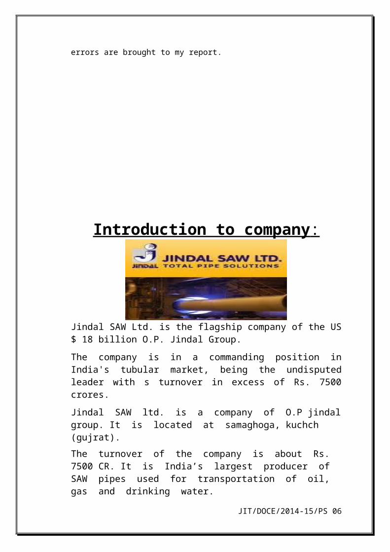
Jindal SAW Ltd. is the flagship company of the US $ 18 billion O.P. Jindal Group.
The company is in a commanding position in India's tubular market, being the undisputed leader with s turnover in excess of Rs. 7500 crores.
Jindal SAW ltd. is a company of O.P jindal group. It is located at samaghoga, kuchch (gujrat).
The turnover of the company is about Rs. 7500 CR. It is India’s largest producer of SAW pipes used for transportation of oil, gas and drinking water.
Installed capacity of 300,000 MT per annum has been enhanced to 500,000 MT per annum by installation of small dia. Pipe plant ( SDP ) with size range DN 80 – DN 250 along with latest linings and coatings. It has its own blast furnace and coke oven facility.
The company is spread in 225 acres with a worforce of more than 2,600 people.
The plant is equipped to provide Zn and Zn-Al coatings and blue/red epoxy or black bitumen coating.
he energy sector for the transportation of oil and gas
Strategic Business Units: Large Diameter Pipes Ductile Iron(DI) Spun Pipes Seamless Tubes &
JIT/DOCE/2014-15/PS 05
Introduction to samaghogha project of jindal
The integrated Greenfield project of Ductile Iron pipe and pig iron unit is a port based facility situated at Samaghogha, Mundra in Gujarat, India, commissioned in 2005. The highlights of our plant are:
Port based facility of Ductile Iron pipes located on Western coast of India
State of the art facility with latest technology.
Installed capacity of 300,000 MT per annum has been enhanced to 500,000 MT per anum by installation of a state of art Small Diameter Plant (SDP), with size range DN 80 – DN 250 along with latest linings /coatings facilities conforming to National/International standards.
Backward Integration with own Blast Furnace & Coke Oven facility to produce & provide a continuous supply of pig iron & coke (main inputs in manufacturing of DI pipes).
Spread in an area of 225 acres with a work force of more than 2,600 people.
Accredited with ISO 9001, ISO 18001 & Product certification for International standards ISO 2531, BS EN 545, BS-EN- 598 and ISO 7186 by British Standards Institute & Bureau Veritas.
The plant has been conforming to various standards like ISO 2531, UNIEN 545 and UNIEN598. It is equipped to provide various coatings such as Zn & Zn-Al Coatings as per National & International Standards and Blue/Red Epoxy or black synthetic paint.
The plant has been conforming to ISO 2531, BSEN 545, BSEN598 and ISO 7186. It also offers various coating facilities like Zn & Zn-Al Coatings as per National & International Standards; Blue/Red Epoxy or Black Bitumen and External and Internal Polyurethane Coatings as per BS EN 15189 and BS EN 15655 respectively for DN 250 to 2200 mm.
JIT/DOCE/2014-15/PS 06

INDEX INDUCTION FURNACEMg CONVERTERCCMANNEALINGZn COATINGTRI-GRINDINGHPTMCEMENT LININGCULTIVATION FURNACEBUFFINGPRE-HEATING FURNACEBITUMEN COATINGPOST HEATING FURNACEDISPATCH AND INSPECTIONBOILER OPERATIONRMHSCPP
JIT/DOCE/2014-15/PS 07

WORKS CARRIED OUT IN SPD II
JIT/DOCE/2014-15/PS 08

1 INDUCTION FURNACE
WHAT IS INDUTION FURNACE?As the name induction furnace it self suggest that it works in induction . The heat generated in the induction furnace is due to the electricity. It is used to maintain the temperature of the hot metal and also the composition of it . percentage of carbon and silica are checked and are matched to the standard % requirement for making of the pipe. The primary objective of induction furnace is to maintain the temperature of hot liquid metal from 1480 to 1500. In induction furnace heating an electrically conducting metal by electromagnetic induction, where eddy current or Foucault current are generated within a meta and resistance leads to joule heating of the metal. Heat may also generated by hysteresis losses in material. Carbon dilution by adding mild steel scrap with the help of fibro feeder. It is an instrument that uses vibration to feed material to a process. It use both vibration and gravity to move material to move material by using two vibro 3ph induction motor having
OPERATING PRINCIPAL Induction furnace works on the principal of induction
Induction furnace is a furnace in which heating is initiated by electricity.Hollow copper coils are provided around furnace in which demineralised water run for cooling, as current generates heat. When current is passed through coils magnetic field is set up due to which eddy currents are generated in molten metal. These eddy currents heats up the molten metal. Direct heating by coils is not possible here as the molten metal will melt the coils.
WORKING AND CONSTRUCTION
There are 3 induction furnace presently in working condition in which 1 furnace is stand by .
JIT/DOCE/2014-15/PS 09

CONSTRUCTION
The furnace consists of an outer cylindrical steel shell hinged at the bottom to facilitate tilting of furnace during pouring.
The inner surface of the shell is covered with an insulating material made of mica or asbestos, while the bottom surface is covered with refractory bricks.
A refractory crucible which contains the charge rests on the brick work and surrounded by a helical coil made of copper tube. The copper tube being a heavy tube requires active cooling and this is achieved by passing a flow of water through it.
The space between the crucible and the shell is packed by a dry refractory mass that provides the necessary insulation.
Working
a) There are three induction furnaces in SDP-II.
JIT/DOCE/2014-15/PS 010

b) The hot metal in the ladle (capacity-25 tons) is unloaded from HMTC with the help of C- clamp operated by crane.
c) This hot metal is then poured in one of the induction furnaces( capacity- 15 tons).
d) A sample of this molten metal( coin shaped) is sent to spectro-lab to obtain the composition of molten metal.
e) Required composition of pipe-C % - 3.80% to 3.95%Si % - 2.0% to 2.15%Mg % - 0.035% to 0.050%
f) Scrap of mild steel is added by a vibratory feeder to reduce C%. Calcined petroleum coke(CPC) is added to increase C%.
g) Silica is added is added directly if the % is low. It is a deoxydising agent and acts as a good flux.
h) The temperature of the molten is measured by pyrometer. It should not be less than 1450 c.
(2) MG CONVERTER
The basic function of a converter is to convert the casting material into ductile material by means of adding magnesium in a molten metal which is coming from an induction furnace.The amount of magnesium mixed in the molten metal is based on the amount of the Sulpher in the molten metal. Mg increase tensile strength and harden ability. Mg blocks are added as per the requirement in the vessel and sealed with cardboards an then it is closed. 0.035% to 0.050% Mg is required Mg also reduce the % of Sulphur in molten metal. Mg converter vessel has a small chamber at rear end inside having 4 holes of 20mm dia. In this chamber Mg blocks along with salt are added and the vessel(containing molten metal) is tilted hydraulically The molten metal mix slowly as it moves in chamber through holes. 30% of Mg is utilized and 70% is vaporized. Salt is added to
prevent blast. Temperature of metal here is 1460-1480C
(3) CCM (CENTRIFUGAL CASTING MACHINE)The hot metal from mg converter is taken to the ccm with the help of ladle. The temp of the hot metal on reaching the ccm is nearly 1400 c.Construction of ccm
JIT/DOCE/2014-15/PS 011
PARTS OF CCM
1.Hooper
2.Fallchute
3.Runner (a) spout inclined at 55 degree
(b) runner tube
(c) ms pipe (for mould spray
(d) nozzle (for mould powder)
(e)rubbing pad
(f) roller blade (to support runner)
(g) runner bogie
4. CCM- sleeve(2 roller bearing ), mould, DC motor, core loader, MTC, runner rollers , water cooling(indirect )
JIT/DOCE/2014-15/PS 012

5. Diabola trolley
6. water jet
7.extractor
8.arms
9. graphite powder
WORKING
CCM works on the principle of centrifugal force, which is provided by a DC motor and 6-V belt drive. The molten metal splashes to periphery of the mould such that it does not drop down again. The molten metal at temperature 1400 C is poured in hoppers capacities 0.8-1 ton.
Hopper is lifted hydraulically, the molten metal passes through fall chute in runner. Meanwhile innocoolant powder is sprinkled at the beginning of runner. The runner is line with graphite powder before the molten metal is poured so that it must no stick to the runner. A nozzle is provided at CCM end to sprinkle mould powder in mould so that pipe can be extracted easily. Meanwhile on the other side he operator the worker loades the core through core loader .
The core gives shape to socket and company designation is given on the core and the year of manufacture. Now the ccm is made to move forward . Its forward motion is due to the main travell cylinder which works on hydraulic. As it move forward the hopper pours the molten metal into the runner from runner it enter the mould . the runner travels fully inside the mould .The mould is rotating at the rpm of 1200. After 12 second of pouring the runner is automatically shifted by dia bola trolley
The pipe is cooled rapidly by water after cooling pipe is extracted through pneumatic extractor. The motion of extractor is due to the roller fixed at rear end. The roller rotates with the help of gear box. From extractor the pipe is shifted to pt trolley and then carried out for annealing
NOTE – whole process in ccm is controlled by plc and is completely interlocked
(3) ANNEALING FURNACE
JIT/DOCE/2014-15/PS 013

Annealing is basically a simple process. The pipe is heated up, held at temperature for some time, then it is slow cooled. If the surface of the pipe is not cleaned after casting then it is cleaned in air.The size of the annealing furnace is 60metre length and 7.8 meter width.There are three zones in annealing furnace namely,Heating zone, Holding zone, Slow cooling zone.
ZONE MIN. TEMP.(® C)
NOM. TEMP.(® C)
MAX. TEMP.(® C)
HEATING ZONE
880 920 960
HOLDING ZONE
920 940 960
SLOW COOLING
660 740 820
The pipe from ccm are bought to annealing furnace. Before the pipes are introduced into the furnace the naming on pipe is don with chalk after that sand is removed through high pressure air and the socket is grinded. After that it is introduced in furnace the pipe are carried inside the furnace through chain which is rotating at 500 mm/min. the chain takes the pipes through various heating zones .
The firing in annealing furnace is initiated by mixture of BF gas and air. This mixture Moves through holes of 16mm dia. in ceramic blocks of 6X4 inches present in burners. The gas burn due to high temperature in furnace. There are valve provided at the top of furnace which allow exhaust and inlet .The position changes after every 40 seconds.In this way temperature of the furnace is maintained. Aligners are provide to ensure pipe.Are not shifted from the path. 12Aligners are provided 6 on both sides which are
JIT/DOCE/2014-15/PS 014
Hydraulically operated.
(5) ZINC COATING
After annealing the pipes are transfer for coating.Zinc coatings provide the most effective and economical way ofprotecting steel against corrosion.Zinc-coating offers the following advantages: • high strength• formability• light weight• corrosion resistance• recyclability• low costZinc coating is by spraying of zinc through electron gun. Zinc deposition is done by rectifier machine using electrolytic deposition technique. 130 gm for single pipe coating is done to prevent from external corrosion.Sometime Zinc Alluminium is also used for coating at external surface.Current is used to melt the Zinc into liquid form. High pressure air is used for spraying the zinc.Pipe rotation = 1350 – 1440 RPM
Air pressure = 5-6 kg/cm^2
QUANTITY OF Zn ( in grams/m^2 )
TROLLEY SPEED ( RPM )
130 800-900
JIT/DOCE/2014-15/PS 015

200 750-850
400 300-400
(6) TRI – GRINDING
Grinding is a finishing process. Three types of grinding are performed in Tri-grinding zone-
a) Socket grinding.b) Socket loop grinding.c) Barrel grinding.
Socket grinding is done by a hand grinder with a grinding tool of an abrasive material. The hand grinder rotates by means of air pressure of about 6.2 bar. It is done to prevent Cutting of gasket. Barrel grinding finishes the inner surface of pipe’s barrel. Three pipes can be Finished together. It is done with the help of grinding tool which is inserted in the barrel, and drive is given by V-belt drive connected to AC motor. After grinding operation pipes are sent for hydrostatic pressure testing
(7) HPTM( HYDRO PRESSURE TESTING MACHINE)
H.P.T.M is done on ductile pipe to identify leakage. High pressure test is done its withstand capacity. It is done by applying high pressure of water internally in the pipe. The deflection of the dial gauge is studied which gives indication for leakage in the pipe.
A hydrostatic pressure of about 35 kg/cm^2 to check water leakage. The whole process is performed in following steps-a) Water is pumped from an underground tank at a pressure
1.8-2 bar and stored in the outer tank.b) This outer tank is half filled with water and in remaining
volume is air. The pressure of air ie. 2 kg/cm^2 forces the water into pipe. Acctuator valve is provided whichinitiate the flow of water in pipes. A non-return valve is also provided to prevent back flow of water.
c) During the time of filling of water in pipes, air is removed through a vent valve.
d) As soon as the vent valves are closed, high pressure pumps are started.
JIT/DOCE/2014-15/PS 016

e) High pressure water is forced in pipes from socket end.f) The spigot end portion of machine has a die connected to
piston and cylinder arrangement.g) In this way pressure in pipes is created of about 35
kg/cm^2.h) After inspection clamping is removed, and water is drained
to the undergroundTank. Push rollers are provided to support pipes of small dia. Like DN-80, DN-100,So that they might not bend or break under such pressure.
i) After clearing hydrostatic pressure test , pipes are ready for cement lining.
(8) CML (CEMENT LINING)
Cement lining is very important as it is recommended by WHO. As thi di pipes are used in water carrying purposes the cement lining plays an important role as the water does not react with the cement. There is strict guidelines for cememnt lining ue to its importance. The thickness of cement lining is fixed and only small variation is allowed in it .
Components of cement lining
a) Zylosb) Mixing tank.c) Slurry tank.d) Slurry trolley.e) Reciprocating pump for cement supply.f) Feed pipes.g) Gas seals.h) Thrust rollers.and Hydro motor
Type of cement used :- SRC cement (export only ), Slag cement(domestic) ,OPC cement (export)Ratio of mixing of cement, sand and water- 1.4 to 1.7 : 1 : 0.40 to 0.55.
The dia of feed pipe is 32 mm
Both the ends of pipes are sealed with gas seals. Cement through feed pipes is feeded in pipes and then by centrifugal action (caused by hydro motor) cement lining is obtained of about 3-4mm as required. Pipes are rotated at 950 RPM on Teflon rollers. Water run continuously during centrifugal action to take the heat of Teflon
JIT/DOCE/2014-15/PS 017

rollers. After checking the cement lining pipes are sent to cultivation furnace.
(9) CULTIVATION FURNACE
The pipes from after cement lining are carried to the cultivation chamber . the cultivation chamber is 100 m long chamber. In this chamber the cement lining is cured by provided required humitidy and temp. The humitdy and the temp inside the furnace is provided by the steam which is coming from the boiler . The pipes are made to travel the 100 m distance in approxx 2 hrs. This tym period is known as curing period .in this period the cement lining of pipes is cured completely. Temperature regulating units – 6 Actuator valves – 12 Chain speed – 1.5m/min
The process of curing is followed as-
Two steam lines are provided, one is for maintaining humidity and other is to maintain temperature.
a) Actuator or butterfly valves are present on both lines to ensure optimum humidity.
b) Around 85% humidity is set on the panel, above it the valve closes.
c) One of the steam line is directly utilized in the furnace for steam supply, other line is passed through a unit comprising blower, radiator, and supply pipes.
d) In temperature regulating unit, blower sucks the air from furnace. This air when strikes the steam tubes, takes up the heat and again it enters the furnace. This cycle repeats again and again. The outlet of steam pipe from radiator goes to a auto condensate pump which takes up the moisture from steam at pressure 3.5 bar and send it to boiler unit at 11 bar.
e) Blowers are provided at the entry and exit of furnace to prevent exit of steam.
(10 ) BUFFING
Buffing is a finishing operation. It finishes the cement lining and makes it smooth. Pipes are hold on PU rubber rollers and supported by push rollers. A barrel buffing tool enters the pipe and it is rotated by 4 V belt drive. Buffing tool is made up of emry
JIT/DOCE/2014-15/PS 018
paper. Pipes are washed by water to remove cement dust after buffing. If any cracks are seen they are filled manually after buffing.
(11) PRE-HEATING FURNACE
Length – 15m
Temperature - 50®C
Pipes are pre-heated so that bitumen could stick to the outer surface and also to remove moisture after buffing. Temperature is set up by same process as in cultivation furnace.
(12) BITUMEN COATING Now before external coating the inner end of the pipe is coated manually for this a small motor is used to rotate the pipes. After that by the help of trolley the pipes are transfer to the external coating machine.Coating is done to prevent corrosion .As per the customer requirement the coating type is selected.There are many types of bitumen coating,some of them are black bitumen, blue epoxy, red epoxy which is selected as per the customer requirement.
CHARACTERISTICS: Coating shall not be applied to any pipe unless its surfaces are
clean, dry and free from rust. Unless otherwise agreed between the purchaser and the
manufacturer all pipes shall be coatedexternally and internally with the same material.
the coating material has a bitumen base,it shall be smooth and tenacious and hard enough notto flow when exposed to a temperature of 65°C butnot so brittle at a temperature of 0°C.
Pipes with or without sockets and flanges whichare imperfectly coated or where the coating does notset or conform to the required quality, the coating shallbe removed and the pipes/flanges recoated.
Pipes thickness should be 70-75 microns , Dia-100mm pipes required 400 gm bituminous and dia-150 mm required 600 gm.
JIT/DOCE/2014-15/PS 019

External coating is of bituminous.
Bitumen or coal-tar coating is mainly used as anti-corrosion material for protection of pipes for industrial and drinking water.
The pipe is fixed on the roller which rotates.
Bitumin sprayed on the pipe by sprayer which is on the top of the machine.
(13) POST HEATING FURNACE
Chamber length – 35m
Temperature inside chamber – 50 to 60®C
Post heating is done to dry the bitumen coating
(14) PACKING AND DISPATCH
Here the pipe from post heating furnace is inspected by the safety officer. He will check the the cml thickness , bitumen thickness,socket thickness etc .If he find the pipe upto the standard then he will mark it ok and the further marking will be done and if it is not upto standard it is rejected .PP,QQ - CCM machine no.
A TO L - January to December ( month)
LOT NO. – A = 0 - 200 Pipes
JIT/DOCE/2014-15/PS 020

B = 201 – 400 Pipes
CLASS – K7, K9, C 40 etc.
LINES – green, yellow etc.
No. of green lines gives pipe length (1- 6m,2 – 5.5m,3 – 5m, 4 – 4.5m)
Yellow- rejected.
The following points are taken under consideration while inspection-
a) Bitumen coating thickness ( measured by coat meter).b) Socket thickness.c) Bore clearance.d) Cement lining thickness.e) Spigot edge taper angle- 15 to 18®.
(15)BOILER OPERATION
Type – fire tube cylindrical.Capacity – 12000 kg/hrWorking pressure – 10.55 kg/cm^2Heating surface area – 305.89 m^2
JIT/DOCE/2014-15/PS 021

WATER PARAMETERS
PH TDS TH
MAKE-UP WATER
7.5-8.5 <200 <100 PPM
SOFT WATER
8.5-9.5 <200 <5 PPM
FEED WATER
8.5-9.5 <200 <5 PPM
BLOW DOWN WATER
11.0-12.0 <3500 <5 PPM
FUEL USED – furnace oil ( FO) and BF gas( CO ).
Burning is initiated by spark and after attaining temperature about 400 ®C , BF gas is supplied to carry on further heating.Water is filtered in sand filter, then resins are added to decrease total hardness ( TH). Finally it is stored in softener tank for feeding in boilers.
(16)RMHS (raw material handling system)
Sand is feeded from storage in a vessel and pumped at 4 kg/cm^2 air pressure to a vibratory feeder. It only permit fine particles to pass through it. This sand is carried through a belt conveyor and after sieving it is stored in zylos. From zylo it is again pumped at pressure 7-8 kg/cm^2 to the bunkers provided in cement lining zone. Cement is also transported in same way. The waste water after cement lining and buffing operation is filtered in a tank,
JIT/DOCE/2014-15/PS 022

where it is also treated by chemicals and it is reused
wherever required.
(17)CPP ( Captive power plant)
Captive power plant is installed with diesel generators. It is a standby power plant. In case there is a shut down in switchyard or monsoon conditions are not preferable, then DG are used. There are total 8 DG in CPP. Total power produced is around 25 MW. DG is simply a diesel engine connected with alternator. Fuel used is either furnace oil or diesel. Governors are also provided to maintain the mean speed.
JIT/DOCE/2014-15/PS 023

RESULTS AND DISCUSSIONS :-
Manufacturing of di pipes is done efficiently
Hydraulics play a very imp role in the manufacturing of di pipes
Largest producer of di pipes ...it export 70% of itz production nd 30% is
domestic
JIT/DOCE/2014-15/PS 024
REFRENCES :-
1. Mr. Bjk nair (AGN MM-SDP2 ).2. Mr. Baby sir (Manager)3. Wikipedia.4. Jindal saw site
JIT/DOCE/2014-15/PS 025