air conditioning technical data fxdq-m9 - daikintech.co.uk · air conditioning technical data...
TRANSCRIPT
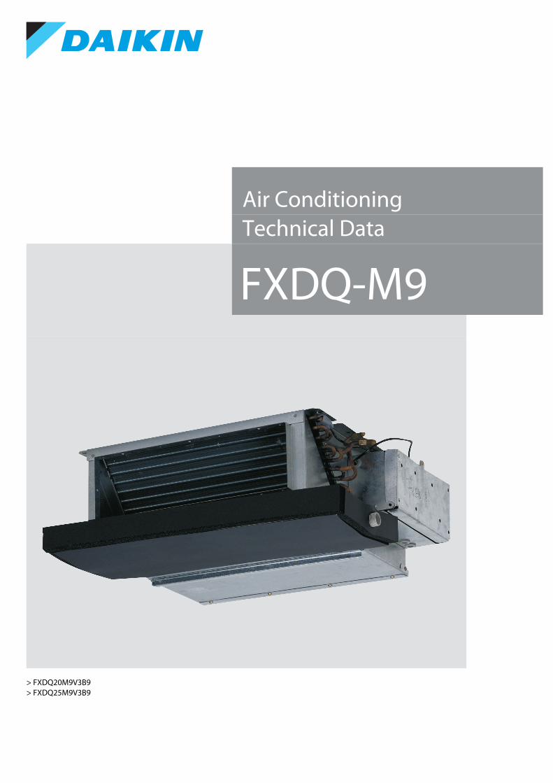
Air ConditioningTechnical Data
FXDQ-M9
> FXDQ20M9V3B9> FXDQ25M9V3B9


• VRV Systems • FXDQ-M9 1
• Indoor Unit • FXDQ-M9
TABLE OF CONTENTSFXDQ-M9
1 Features . . . . . . . . . . . . . . . . . . . . . . . . . . . . . . . . . . . . . . . . . . . . . . . . . . . . . . . . . . . . . 2
2 Specifications . . . . . . . . . . . . . . . . . . . . . . . . . . . . . . . . . . . . . . . . . . . . . . . . . . . . . . . 3Technical Specifications . . . . . . . . . . . . . . . . . . . . . . . . . . . . . . . . . . . . . . . . . . . . . 3Electrical Specifications . . . . . . . . . . . . . . . . . . . . . . . . . . . . . . . . . . . . . . . . . . . . . . 4
3 Electrical data . . . . . . . . . . . . . . . . . . . . . . . . . . . . . . . . . . . . . . . . . . . . . . . . . . . . . . . 5
4 Safety device settings. . . . . . . . . . . . . . . . . . . . . . . . . . . . . . . . . . . . . . . . . . . . . . 6
5 Options. . . . . . . . . . . . . . . . . . . . . . . . . . . . . . . . . . . . . . . . . . . . . . . . . . . . . . . . . . . . . . . 7
6 Capacity tables . . . . . . . . . . . . . . . . . . . . . . . . . . . . . . . . . . . . . . . . . . . . . . . . . . . . . 8Cooling Capacity Tables . . . . . . . . . . . . . . . . . . . . . . . . . . . . . . . . . . . . . . . . . . . . . 8Heating Capacity Tables . . . . . . . . . . . . . . . . . . . . . . . . . . . . . . . . . . . . . . . . . . . . . 9Capacity Correction Factor . . . . . . . . . . . . . . . . . . . . . . . . . . . . . . . . . . . . . . . . . . 10
7 Dimensional drawings . . . . . . . . . . . . . . . . . . . . . . . . . . . . . . . . . . . . . . . . . . . . 12
8 Piping diagrams . . . . . . . . . . . . . . . . . . . . . . . . . . . . . . . . . . . . . . . . . . . . . . . . . . . 13
9 Wiring diagrams . . . . . . . . . . . . . . . . . . . . . . . . . . . . . . . . . . . . . . . . . . . . . . . . . . . 14Wiring Diagrams - Single Phase . . . . . . . . . . . . . . . . . . . . . . . . . . . . . . . . . . . . 14
10 Sound data . . . . . . . . . . . . . . . . . . . . . . . . . . . . . . . . . . . . . . . . . . . . . . . . . . . . . . . . . 15Sound Level Data . . . . . . . . . . . . . . . . . . . . . . . . . . . . . . . . . . . . . . . . . . . . . . . . . . . 15Sound Pressure Spectrum . . . . . . . . . . . . . . . . . . . . . . . . . . . . . . . . . . . . . . . . . . 16

• Indoor Unit • FXDQ-M9
1
2
1 Features
oor Unit Systems Q-M9 ll concea
Ind VRV FXD Sma Designed for hotel applications• Compact unit (230mm high & 652mm deep), can easily be mounted in narrow ceiling voids
• Discretely concealed in the ceiling: only the suction and discharge grilles are visible
• Flexible installation, as the air suction direction can be altered from rear to bottom suction
• For easy mounting, the drain pan can be located to the left or right of the unit
Inverter Home leave operation
Fan only Auto cooling-heating
changeover
Fan speed steps
Dry programme Air filter Weekly timer Infrared remote control
Wired remote control
Centralised control
Auto-restart Self diagnosis Multi tenant
• VRV Systems • FXDQ-M9

3
2
• Indoor Unit • FXDQ-M9
2 Specifications
2-1 Technical Specifications FXDQ20M9 FXDQ25M9
Cooling capacity Nom. kW 2.2 (1) 2.8 (1)Heating capacity Nom. kW 2.5 (2) 3.2 (2)Power input - 50Hz Cooling Nom. kW 0.050 (1)
Heating Nom. kW 0.050 (2)Required ceiling void \> mm 250Dimensions Unit Height mm 230
Width mm 502Depth mm 652
Packed unit Height mm 301Width mm 584Depth mm 753
Weight Unit kg 17Packed unit kg 18
Casing Colour UnpaintedMaterial Galvanised steel
Heat exchanger Rows Quantity 2Fin pitch mm 1.4Passes Quantity 2Face area m² 0.108Stages Quantity 12Empty tubeplate hole
Quantity 4 0
Tube type ø7 Hi-XSSFin Type Symmetric waffle louvre
Treatment HydrophilicLength mm 430
Fan Type Sirocco fanQuantity 1Air flow rate - 50Hz Cooling High m³/min 6.7 7.4
Low m³/min 5.2 5.8Heating High m³/min 6.7 7.4
Low m³/min 5.2 5.8Fan motor Quantity 1
Model Step motorSpeed Steps 2Output High W 10Drive Direct drive
Air filter Type Resin net with mold resistanceSound power level Cooling Nom. dBA 50Sound pressure level Cooling High dBA 37
Low dBA 32Heating High dBA 37
Low dBA 32Refrigerant Type R-410A
Control Electronic expansion valvePiping connections Liquid Type Flare connection
OD mm 6.35Gas Type Flare connection
OD mm 12.7Drain I.D. 21.6, O.D. 27.2
Temperature control Microprocessor thermostat for cooling and heatingAir direction control Up and downwardsSafety devices Item 01 PC board fuse
02 Fan motor thermal protectionControl systems Infrared remote control BRC4C62
Wired remote control BRC1E53A / BRC1E53B / BRC1E53C / BRC1D52Simplified wired remote control for hotel applications
BRC2E52C (heat recovery type) / BRC3E52C (heat pump type)
• VRV Systems • FXDQ-M9 3

• Indoor Unit • FXDQ-M9
2
4
2 Specifications
Notes
(1) Cooling: indoor temp. 27°CDB, 19°CWB; outdoor temp. 35°CDB; equivalent piping length: 8m; level difference: 0m
(2) Heating: indoor temp. 20°CDB; outdoor temp. 7°CDB, 6°CWB; equivalent refrigerant piping: 8m; level difference: 0m
Capacities are net, including a deduction for cooling (an addition for heating) for indoor fan motor heat.
Voltage range: units are suitable for use on electrical systems where voltage supplied to unit terminal is not below or above listed range limits.
Maximum allowable voltage range variation between phases is 2%.
MCA/MFA: MCA = 1.25 x FLA
MFA \< 4 x FLA
Next lower standard fuse rating minimum 16A
Select wire size based on the value of MCA
Instead of a fuse, use a circuit breaker
Contains fluorinated greenhouse gases
2-2 Electrical Specifications FXDQ20M9 FXDQ25M9
Power supply Name V1Phase 1~Frequency Hz 50Voltage V 230
Voltage range Max. % 10Min. % -10
Current - 50Hz Minimum circuit amps (MCA) A 0.2Maximum fuse amps (MFA) A 16Full load amps (FLA)
Total A 0.1
Zmax List No requirements
• VRV Systems • FXDQ-M9

3
3
• Indoor Unit • FXDQ-M9
3 Electrical data3 - 1 Electrical Data
• VRV Systems • FXDQ-M9 5

• Indoor Unit • FXDQ-M9
4
6
4 Safety device settings4 - 1 Safety Device Settings
3TW25511-3
FXDQ20M9 FXDQ25M9FAN MOTOR THERMAL PROTECTOR °C OFF:135±8, (ON:87±15)
PC BOARD FUSE 250V 10A
• VRV Systems • FXDQ-M9

3
5
• Indoor Unit • FXDQ-M9
5 Options5 - 1 Options
FXDQ-M9
���������� ���� �� �� �� �� ��������������������������
�������������������� ���� �� �� �� �
�������������� ����
������� ���
! "�����#��������������������$����������������������������%������& "�����#��������������������$�������������������������������%������' (�������#���$�����)�� ��������������#����������������������������)�! ��������������#��������������������������!�* �������������+ �������������%�,�#�������������-. ����������������������.�� /����������%�,�$��������������������&�%���0��1 2��#���� �3 44�����������1�� /����������%�,�$��������������������!�%���0��1�! ������#�������#������������������������#���������5 "��������������� /,���������������#����������������������������������������������� 6����7��������������! 8��������������������
�9�� ��:�������������������%�,�#�������������-�9!� (���������������0����9&� ����0�����������������������������$�����5������7���������������������9'� ����������������������;�/������<�=�����<�4�����<��������<�"������<�����������<�����8�����
�9)� ����������������������;�/������<��>���<���������<����������<�"��?�����<���������<�����-���������
�9*� ����������������������;�/������<��������<�=���0<���0���<�������<�(�%�����<�����"��?�0��9+� ����������������������;
@�����������0��;�/������<�=�����<�4�����<�8����<�"������<��������<���������������� ���������%���/A���(-&�������%��������$��������2������������#�$���<������������������������������������������;
@�����������0�!;�/������<�-��������<���������<��>���<����������<���������<�����"��?������@�����������0�&;�/������<�=���0<�������<��������<�"��%���<�"��?�0<�������0����
�9.� ��������%���������%��������$����-��!3&/)!�+����-���/)&(3-3�+��91� @�����������0�&��#�������������-���/)&�+������##������#����������#������������-��!3&/)!�+�
�����������������������������8���������� B������
���"��?������������������%��
8"&5�-)�8(�5'(*������9��/A6(������9&�
-��+()������9����9.�
���������������������������������=�������%��#�����5(
A���-�5�8�"&5!�)�AC-&��(8�"&5�-)�AC-!�!(A/A!*7�(
-��!/)!�+�����9+��91�-��&/)!�+�����9+��91�
A���-*������9��A��!()�����9��A��'()�����9��A��"5�7�
/A���-!�����9��
� -���8)!-���/)&(+���9'�-���/)&-+���9)�
-���/)&�+���9*��91�-��'�*!-��'�*'
���� �!"# �
• VRV Systems • FXDQ-M9 7

• Indoor Unit • FXDQ-M9
6
8
6 Capacity tables6 - 1 Cooling Capacity Tables
Unit size
Indoor air temp.14.0 °CWB 16.0 °CWB 18.0 °CWB 19.0 °CWB 20.0 °CWB 22.0 °CWB 24.0 °CWB20.0 °CDB 23.0 °CDB 26.0 °CDB 27.0 °CDB 28.0 °CDB 30.0 °CDB 32.0 °CDB
TC SHC TC SHC TC SHC TC SHC TC SHC TC SHC TC SHC
20 1.5 1.4 1.8 1.6 2.1 1.7 2.2 1.8 2.3 1.8 2.4 1.8 2.4 1.7
25 1.9 1.6 2.3 1.8 2.6 2.0 2.8 2.1 3.0 2.2 3.0 2.1 3.1 2.0
NOTES - OPMERKINGEN - REMARQUES - ANMERKUNGEN - NOTAS - NOTE - - NOTLAR -
FXDQ-M9
Cooling Capacity TC: Total capacity; kWSHC: Sensible heat capacity; kW
1 This table is for the selection of indoor equipment. Deze tabel is bedoeld voor het kiezen van de binnenunit.Ce tableau concerne la sélection de l’équipement intérieur. Diese Tabelle ist für die Auswahl der Innenanlagen. Esta tabla es para seleccionar el equipo interior. Usare questa tabella per la selezione delle apparecchiature interne.
2 In the event that conditions differ due to the design requirements after system selection, actual operating ability of the indoor equipment will differ from that noted in the table because of changes in the outdoor air temperature and load factor. Als nadat u het systeem hebt gekozen de voorwaarden afwijken van de ontwerpvereisten, dan zal het reële bedrijfsvermogen van de binnenunit afwijken van de in de tabel vermelde gegevens, wegens de afwijkende buitenluchttemperatuur en de belastingsfactor.
extérieure et du facteur de charge. Falls Bedingungen aufgrund der Konstruktionsanforderungen nach der Systemauswahl abweichen, dann weicht aufgrund der Änderungen der Außenlufttemperatur und des Lastfaktors die tatsächliche Betriebsfähigkeit der Innenanlage von der in der Tabelle aufgeführten ab.
del equipo interior diferirá de la que se muestra en la tabla debido a los cambios de la temperatura de aire exterior y al factor de carga. Nel caso in cui intervenissero dei cambiamenti nelle condizioni dovuti a requisiti di progettazione successivi alla selezione del sistema, la capacità operativa effettiva delle apparecchiature interne sarà diversa da quella indicata in tabella a causa della diversa temperatura dell’aria esterna e del fattore di carico.
3 In this case, use the ability table for the indoor equipment selected and correct for the ratio of change in ability. Gebruik in dat geval de vermogenstabel van de gekozen binneninstallatie en kies het juiste vermogen.
Verwenden Sie in diesem Fall die Fähigkeit für die ausgewählte Innenanlage und korrigieren Sie das Verhältnis der Änderung in der Fähigkeit. En este caso, utilice la tabla de capacidades del equipo interior seleccionado y corrija la relación de cambio en capacidad.
percentuale di cambiamento di capacità.
3TW25772-1A
• VRV Systems • FXDQ-M9

3
6
• Indoor Unit • FXDQ-M9
6 Capacity tables6 - 2 Heating Capacity Tables
Unit sizeIndoor air temp. °CDB
16.0 18.0 20.0 21.0 22.0 24.0kW kW kW kW kW kW
20 2.6 2.6 2.5 2.4 2.3 2.2
25 3.4 3.4 3.2 3.1 3.0 2.8
NOTES - OPMERKINGEN - REMARQUES - ANMERKUNGEN - NOTAS - NOTE - - NOTLAR -
FXDQ-M9
Heating Capacity
1 This table is for the selection of indoor equipment. Deze tabel is bedoeld voor het kiezen van de binnenunit.Ce tableau concerne la sélection de l’équipement intérieur. Diese Tabelle ist für die Auswahl der Innenanlagen. Esta tabla es para seleccionar el equipo interior. Usare questa tabella per la selezione delle apparecchiature interne.
2differ from that noted in the table because of changes in the outdoor air temperature and load factor.
extérieure et du facteur de charge.
der Außenlufttemperatur und des Lastfaktors die tatsächliche Betriebsfähigkeit der Innenanlage von der in der Tabelle aufgeführten ab.
la capacità operativa effettiva delle apparecchiature interne sarà diversa da quella indicata in tabella a causa della diversa temperatura dell’aria esterna e del fattore di carico.
3
Fähigkeit.
percentuale di cambiamento di capacità.
3TW25512-2B
• VRV Systems • FXDQ-M9 9

• Indoor Unit • FXDQ-M9
6
10
6 Capacity tables6 - 3 Capacity Correction Factor
FXDQ-M9
How to use this table:Capacity: Total capacity for High sensible mode = Total capacity for normal capacity table X TC ratio.SHF: SHF for High sensible mode = SHF for normal capacity table X SHF ratio. In case of SHF is bigger than 1, SHF is “1”When selecting units for mixed (RA DX indoor units + VRV DX indoor unit),• Correction Ci corresponds with Te = 9°C TC ratio value for each type of Indoor unit,
depending on indoor ambient design temperature X/Y °CDB/°CWB• Correction Ct corresponds with Te = 9°C TC ratio value for each type of indoor unit,
depending on indoor ambient temperature 29/19 °CDB/°CWB
So verwenden Sie diese Tabelle:Leistung:Gesamtleistung (GL) für hochfühlbaren Leistungsmodus = Gesamtleistung für normale Leistungstabelle x GL-Verhältnis.SHF: SHF für hochfühlbaren Leistungsmodus = SHF für normale Leistungstabelle x SHF-Verhältnis. Für den Fall, dass SHF größer als 1 ist, wird SHF als “1” angenommen.Bei Auswahl gemischter Geräte (RA DX-Innengerät + VRV DX-Innengerät),• Korrektur Ci entspricht dem GL-Verhältniswert für Te = 9 °C für jeden Innengerätetyp, in
Abhängigkeit von der Innen-Entwurfstemperatur X/Y °C TK/°C FK• Korrektur Ct entspricht dem GL-Verhältniswert für Te = 9 °C für jeden Innengerätetyp, in
Abhängigkeit von der Innentemperatur 29/19 °C TK/°C FK
• i
• t
Cómo utilizar esta tabla:Capacidad: capacidad total para el modo sensible alto = capacidad total para relación TC de tabla X de capacidad normal.SHF: SHF para modo sensible alto = SHF para relación SHF de tabla X de capacidad normal. En caso de que SHF sea superior a 1, SHF es “1”Si se seleccionan unidades combinadas (Unidades interiores DX RA + unidades interiores DX VRV),• La corrección Ci corresponde a Te = 9°C valor de relación TC para cada tipo de unidad
interior, en función de la temperatura de diseño ambiente interior X/Y °CBS/°CBH• La corrección Ct corresponde a Te = 9°C valor de relación TC para cada tipo de unidad
interior, en función de la temperatura ambiente interior 29/19 °CBS/°CBH
Comment utiliser ce tableau :Puissance :Puissance totale pour le mode haute sensibilité = Puissance totale indiquée dans le tableau de puissance normale X rapport PT.FCS : FCS pour le mode haute sensibilité = FCS indiqué dans le tableau de puissance normale X rapport FCS. Si le FCS est supérieur à 1, le FCS correspond à « 1 »Lors de la sélection d’unités pour une installation mixte (unités intérieures DX RA + unité intérieure DX VRV),• La correction Ci correspond à Te = 9 °C / valeur de rapport PT pour chaque type d’unité
intérieure, pour une température ambiante intérieure de calcul de X/Y °CBS/°CBH• La correction Ct correspond à Te = 9 °C / valeur de rapport PT pour chaque type d’unité
intérieure, pour une température ambiante intérieure de 29/19 °CBS/°CBH
Come utilizzare questa tabellaCapacità: Capacità totale per modalità ad alta capacità sensibile = Capacità totale per tabella capacità normali X rapporto TC.SHF: SHF per modalità ad alta capacità sensibile = SHF per tabella capacità normali X rapporto SHF. Qualora il valore SHF sia maggiore di 1, SHF è “1”Quando si selezionano unità combinate (unità interna ad espansione diretta RA+ unità interna ad espansione diretta VRV ),• La correzione Ci corrisponde a Te = 9°C valore rapporto TC per ogni tipo di unità interna, in
base alla temperatura interna di progetto X/Y °CBS/°CBU• La Correzione Ct corrisponde a Te = 9°C valore rapporto TC per ogni tipo di unità interna, in
base alla temperatura interna di progetto 29/19 °CBS/°CBU
Hoe deze tabel gebruiken:Vermogen: totaal vermogen voor High Sensible-modus = totaal vermogen voor tabel normaal vermogen x ratio TV.SHF: SHF voor High Sensible-modus = SHF voor tabel normaal vermogen x ratio SHF. Indien SHF groter is dan 1, is SHF “1”Bij het selecteren van units voor gemengd gebruik (RA DX-binnenunits + VRV DX-binnenunits),• Correctie Ci komt overeen met ratiowaarde Te = 9°C TC voor elk type binnenunit, afhankelijk
van de ontwerptemperatuur van de binnenunit X/Y °CDB/°CNB• Correctie Ct komt overeen met ratiowaarde Te = 9°C TC voor elk type binnenunit, afhankelijk
van de omgevingstemperatuur van de binnenunit 29/19 °CDB/°CNB
VRV DX):• i
• t
Kapasite: Yüksek hassasiyet modu toplam kapasitesi = Normal kapasite tablosu için toplam kapasite
SHF, 1’den büyük ise SHF “1”dir
• Ci
• Ct
3D079901A
Capacity correction factor Te = 9°CIndoor air
temperature14.0 °CWB 16.0 °CWB 18.0 °CWB 19.0 °CWB 20.0 °CWB 22.0 °CWB 24.0 °CWB20.0 °CDB 23.0 °CDB 26.0 °CDB 27.0 °CDB 28.0 °CDB 30.0 °CDB 32.0 °CDB
FXDQ20M9 TC 0.682 0.696 0.757 0.783 0.807 0.833 0.856SHF 1.131 1.174 1.116 1.092 1.072 1.054 1.050
FXDQ25M9 TC 0.684 0.706 0.775 0.797 0.813 0.838 0.861SHF 1.133 1.164 1.105 1.085 1.071 1.054 1.048
• VRV Systems • FXDQ-M9

3
6
• Indoor Unit • FXDQ-M9
6 Capacity tables6 - 3 Capacity Correction Factor
FXDQ-M9
3D079901
Capacity correction factor Te = 11°CIndoor air
temperature14.0 °CWB 16.0 °CWB 18.0 °CWB 19.0 °CWB 20.0 °CWB 22.0 °CWB 24.0 °CWB20.0 °CDB 23.0 °CDB 26.0 °CDB 27.0 °CDB 28.0 °CDB 30.0 °CDB 32.0 °CDB
FXDQ20M9 TC 0.547 0.564 0.585 0.626 0.663 0.719 0.754SHF 1.131 1.224 1.270 1.209 1.163 1.108 1.092
FXDQ25M9 TC 0.546 0.570 0.605 0.647 0.681 0.725 0.761SHF 1.133 1.221 1.249 1.192 1.153 1.109 1.089
• VRV Systems • FXDQ-M9 11

• Indoor Unit • FXDQ-M9
7
12
7 Dimensional drawings7 - 1 Dimensional Drawings
FXDQ-M9
3TW25774-1
(Suspension position)
250 o
r more
(Suspe
nsion p
osition
)
300 or more
Nr Part name1 Liquid pipe connection (ø 6.35)2 Gas pipe connection (ø 12.7)3 Drain hole (o.d. ø 27.2 - i.d. ø 21.6)4 Transmission wiring port5 Power supply wiring port6 Service space7 Switch box8 Nameplate
• VRV Systems • FXDQ-M9

3
8
• Indoor Unit • FXDQ-M9
8 Piping diagrams8 - 1 Piping Diagrams
• VRV Systems • FXDQ-M9 13

• Indoor Unit • FXDQ-M9
9
14
9 Wiring diagrams9 - 1 Wiring Diagrams - Single Phase
FXDQ-M
2TW23666-1E
NOTES
1 Use copper conducters only.2 When using the central remote control, see manual for connection to the unit.3 When installing the electric heating change the wiring for the heater circuit. The main power supply has to be supplied independently. 4 When connecting the input wires from outside, ‘forced off’ or ‘on/off’ operartion can be selected by the remote control. See installation manual for details.
A1P Printed circuit board RyF1-3 Magnetic relay (Fan) Adapter for wiringC1R Capaciter (Fan) T1R Transformer (220-240V/22V) Ryc, Ryf Magnetic relayF1U Fuse (250V, 10A) X1M Terminal strip (power) Ryh Magnetic relay (J1EH)F2U Field fuse X2M Terminal strip (control) F1U, F2U Fuse (250V, 5A)HAP Light emitting diode(Service monitor-green) Y1E Electric expansion valve X1A,X2A Connector (wiring adapter)M1F Motor (fan) Optional parts X1M Terminal stripQ1E Earth leak detector J1EH Electric heater Connector for optional partsR1T Thermistor (air) K1R Magnetic relay (J1EH) X16A Connector (wiring adapter)
R2T,R3T Thermistor (refrigerant) X18A Connector (wiring adapter for electronical appendices)
: Connector L : Live
: Protective earth (screw) N : Neutral
: Wire clamp
: Field wiring
Note 3 Input from outside
Compressor operation
Switch box cover
Switch box
Indoor
Adap
ter fo
r wirin
g
Fan operation
Wired remote control
20,25 Class(22,28 Class)
Central remote control note1
Term
inals
oper
ation
ind
icator
• VRV Systems • FXDQ-M9

3
10
• Indoor Unit • FXDQ-M9
10 Sound data10 - 1 Sound Level Data
FXDQ-M9
NOTES
1 dBA = A-weighted sound pressure level (A-scale according to IEC).
2 Reference acoustic pressure 0 dB = 20 Pa.
3 These operating values were obtained using a power source of 230V/50Hz.
4 These operating values were obtained in a dead room (conversion values). Noise values will vary depending on a range of factors such as the construction of the particular room in which the equipment is installed.
5 Operating noise differs with operation and ambient conditions.
ModelSound pressure level - 230V
Sound power levelH L Measuring location
FXDQ20M9 37 32 50
FXDQ25M9 37 32 50
Suction Unit DuctDischarge
Microphone
Location of microphone
• VRV Systems • FXDQ-M9 15

• Indoor Unit • FXDQ-M9
10
16
10 Sound data10 - 2 Sound Pressure Spectrum
FXDQ20M9 3TW21467-1
Octave band frequency (Hz)
Soun
d pr
essu
re le
vel (
dB)
FXDQ25M9 3TW21477-1
Octave band frequency (Hz)
Soun
d pr
essu
re le
vel (
dB)
• VRV Systems • FXDQ-M9

Daikin Europe N.V. Naamloze Vennootschap - Zandvoordestraat 300, B-8400 Oostende - Belgium - www.daikin.eu - BE 0412 120 336 - RPR Oostende
EEDEN17 02/17
The present leaflet is drawn up by way of information only and does not constitute an offer bindingupon Daikin Europe N.V.. Daikin Europe N.V. has compiled the content of this leaflet to the best ofits knowledge. No express or implied warranty is given for the completeness, accuracy, reliability orfitness for particular purpose of its content and the products and services presented therein. Specifi-cations are subject to change without prior notice. Daikin Europe N.V. explicitly rejects any liability forany direct or indirect damage, in the broadest sense, arising from or related to the use and/or inter-pretation of this leaflet. All content is copyrighted by Daikin Europe N.V.