alignment
TRANSCRIPT
Training Module ALIGNMENT
WHAT IS ALIGNMENT?
When machine shafts are in their own geometrical position, they are known in alignment.Two parallel shafts are called in alignment in case of spur and helical gearing, belt drive, etc. For bevel gear, the shaft should intersect to each other. For coupling drive, the shaft axes should be collinear.
ALIGNMENT OF COUPLING:When axes of two shafts which to be coupled each other to transmit motion and power, are collinear is known in alignment.
ILL EFFECTS OF MISALIGNMENT: Following may be the ill effect of misalignment:(a) Too much noise and vibration(b) Too much heat generation(c) Too much power consumption(d) More wear and tear of coupling components and bearing(e) Frequent damage and failure of bearing and gears
ASHISH KUMAR SINGH Page 1

Training Module ALIGNMENT
(f) Chances of failing lubrication of bearings and gears(g) Chances of getting loose the coupling and foundation bolts(h) Frequent failure of gland packing and oil seal(i) Value of misalignment will go on increasing(j) Unbalancing effect(k) Much more stress concentration and fatigue failure(l) More down time and maintenance cost(m)Poor job qualityREASONS OF MISALIGNMENT: Following may be the reasons of misalignment of coupling:(a) Inaccuracy in alignment in initial condition(b) High torque transmitted through the coupling(c) Frequent shock load on the machine(d) Too high coupling speed(e) Unequal temperature rise in two shafts(f) Foundation bolts and coupling bolts are not tightened properly(g) Smaller sized foundation(h) Setting, seasoning or spinning the foundation(i) Undersized foundation bolts and coupling bolts(j) Smaller sized coupling used
ASHISH KUMAR SINGH Page 2

Training Module ALIGNMENT
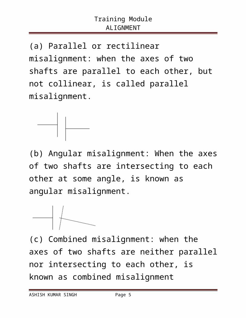
(k) Missing coupling bolts(l) General bolts used instead of machine bolts(m)Unbalanced rotating components(n) Improper mounting of bearings on shaft and housing(o) Wear of bearing(p) Soft foot of machine bed(q) More nos. of packing used(r) Bend shaft TYPES OF COUPLING MISALIGNMENT:There are the three types:(a) Parallel or rectilinear misalignment: when the axes of two shafts are parallel to each other, but not collinear, is called parallel misalignment.
(b) Angular misalignment: When the axes of two shafts are intersecting to each other at some angle, is known as angular misalignment.
ASHISH KUMAR SINGH Page 3

Training Module ALIGNMENT
(c) Combined misalignment: when the axes of two shafts are neither parallel nor intersecting to each other, is known as combined misalignment
INSTRUMENTS, TOOLS AND OTHER ACCESSORIES USED FOR ALIGNING:
PROCEDURE FOR ALIGNING COUPLINGS:Before aligning couplings mounted on two shafts, following pre-checks are required:
ASHISH KUMAR SINGH Page 4
Training Module ALIGNMENT
(a) The diameters of both the coupling should be measured. The both diameters should be exactly the same.
(b) The concentricity of coupling on shaft:
The axes of coupling and shaft should be collinear. A dial test indicator plunger is placed with preload and dial zero setting on the coupling periphery with its stand on some firm base. Coupling is rotated individually to know the deviation in DTI. If there is no deviation, the coupling is concentric on shaft, otherwise not. If there is some small deviation, it should be noted at four 90o position of coupling. It helps us at the time checking parallel misalignment. Following may be the reasons for eccentricity of coupling:- Improper machining of coupling hole in the center.
ASHISH KUMAR SINGH Page 5

Training Module ALIGNMENT
- Improper way of mounting coupling on shaft- Too much clearance between hole and shaft- Improper size of key fitted between them- Bend shaft
(c) Perpendicularity of coupling face on shaft axis: The face of coupling should be mounted exactly at right angle on shaft axis. It is again checked with DTI method. DTI plunger is faced on coupling face with preload and zero dial setting. Coupling is rotated. Any deviation in reading shows inaccuracy in perpendicularity of coupling on shaft. If the value is mall, it is noted at four right angled positions. It helps while checking angular misalignment. Following may be the reasons of angular misalignment:- Improper machining of coupling hole in the center.- Improper way of mounting coupling on shaft- Too much clearance between hole and shaft- Improper size of key fitted between them- Bend shaft
ASHISH KUMAR SINGH Page 6

Training Module ALIGNMENT
(d) Soft foot of the machine bed: it is checked by inserting thin leaf of feeler gauge underside of each foundation bolt positions. The foundation bolts should not be in tighten position while checking the soft foot.
(e) Identifying Stationary machine (SM) and Machine to bee shimmed (MTBS):Normally the machine part which can be lifted or shifted from its position easily, is selected as MTBS. SM position of machine parts must have some initial height from MTBS.
(f) Leveling of shaft: It is sometimes becomes more useful while aligning, specially in case of long line shaft.
ASHISH KUMAR SINGH Page 7
Training Module ALIGNMENT
(g) Types of coupling used.
(h) Scratches, rust and corrosion, dents, etc. on coupling periphery and face.Mark coupling periphery at four points at 90o apart. Check all foundation bolts are fully tight.Check angular misalignment in vertical plane first. For checking angular misalignment in vertical plane, measure top and bottom gaps between coupling with taper gauge. If taper gauge is not available, use feeler gauge.Measure distances of front foot bolt and rare foot bolt position of MTBS from coupling end.Calculate the thickness of shims from the following formula
ASHISH KUMAR SINGH Page 8

Training Module ALIGNMENT
x = {(TG – BG)/D}L1 & y = {(TG – BG)/D}L2Where, x = Thickness of shims under front foot bolt positiony = Thickness of shims under rare foot bolt positionTG = Top gap between couplingBG = Bottom gap between couplingD = Diameter of couplingL1 = Distance of front foot bolt position from coupling faceL2 = Distance of rare foot bolt position from coupling face
Insert (if x & y are positive) or remove (if x & y are negative) shims equal to calculated thickness (x and y) under respective bolt positions after lifting MTBS with suitable device. Tighten all the bolts. Measure top and bottom gap again. Add shims equal to soft foot if there is any amount found in pre-checks.Measure front and back gap between the coupling with taper gauge or feeler gauge and shift MTBS to remove angular misalignment in horizontal plane.Check parallel misalignment in vertical plane. Place a straight edge on the top of both the coupling
ASHISH KUMAR SINGH Page 9

Training Module ALIGNMENT
and measure the gap with feeler gauge if any found between the straight edge and coupling. Insert or remove shims from all four bolt position to remove parallel misalignment from vertical plane.Check the parallel misalignment in horizontal plan with straight edge and make it correct by shifting MTBS.Mount a DTI base on SM coupling with suitable fixture and DTI plunger on the periphery of MTBS coupling top with preload and zero dial setting to remove parallel misalignment from vertical plane further.
Rotate SM shaft till the DTI comes to down most position. Check he readings in DTI.Insert (for positive value) or remove (for negative value) the shims equal to half the reading of dial test
ASHISH KUMAR SINGH Page 10

Training Module ALIGNMENT
indicator under all four bolt positions. Check the readings again on top and bottom.Check the reading of DTI on front and back side of the coupling and shift the MTBS parallel to axis to remove angular misalignment in horizontal plane.Do the whole process again, still there is some misalignment between couplings.LIMITATIONS:
Both coupling diameter may not be the same.Non-availability of taper gauge and unskilled way of using feeler gauge to measure coupling gap.Peripheral surface of coupling is not free from rust and corrosion, scratch, etc.Eccentric coupling on shaft.Non-perpendicular coupling face on shaft.Too much gap between coupling face like fluid coupling.Sagging of DTI fixture.Inadequate space for rotating DTI fixture 360o around the coupling.Following may be the way for aligning coupling under these situations:
ASHISH KUMAR SINGH Page 11

Training Module ALIGNMENT
If coupling diameters are not the equal, use DTI to check and correct parallel misalignment. If taper gauge is not available, use feeler gauge to know the gap with a depth of maximum 10 mm. Gap can be checked also by using DTI fixing the plunger on the back side of the face of the coupling and base on other side shaft. Too much gap can be checked with the same method. In case of eccentric and non-perpendicular coupling and corroded coupling, couple both the coupling with a loose bolt an do the alignment as explained earlier. Sagging of DTI fixture can be checked separately and the value is being taken care while calculating the thickness of shims for removing misalignment. Algebraic sum of the readings taken at 3 ‘O’ clock and 9 ‘O’ clock of DTI gives the value for 6 ‘O’ clock. It avoids rotating of DTI fixture 360o around the coupling.
SAFETY PRECAUTIONS:Must check the capabilities of all tools and tackles which will be used for lifting purpose.Shims and liners must not have sharp edges.
ASHISH KUMAR SINGH Page 12

Training Module ALIGNMENT
Shims and liners should be made of adequate dimensions.While lifting and inserting shims, beware of catching fingers between bed and foundation.Proper sized spanners should be used while tightening the bolts. Never use spanners with pipes for increasing the length.Worn-out spanners, screw spanners and pipe spanners must not be used for tightening bolts.Never keep straight edge on rough corroded and hot surface.Never rotate DTI plunger on rough surface of couplings.Use minimum numbers of liners or shims underside of machine bed.Use proper PPE while working.
ASHISH KUMAR SINGH Page 13