ravaglioli td1760ws wheel alignment...
TRANSCRIPT

Ravaglioli TD1760WS Wheel Alignment System
Operational Procedures

SAFELY TURNING ON AND TURNING OFF THE SYSTEM This is the program’s main screen.
To turn on the program- Set rocker switch on rear of cabinet to the ON position. To turn off the system- Return to the main screen and select the red key. When the message appears on screen “It is now safe to turn off your computer” turn rocker switch on rear of cabinet to the off position. WARNING: TURNING THE SYSTEM OFF USING ANY OTHER METHOD COULD RESULT IN DAMAGE TO THE COMPUTER. Alignment in Four Colors- Only four color coded keys operate the software. Each sensor head is a fully functional remote control.
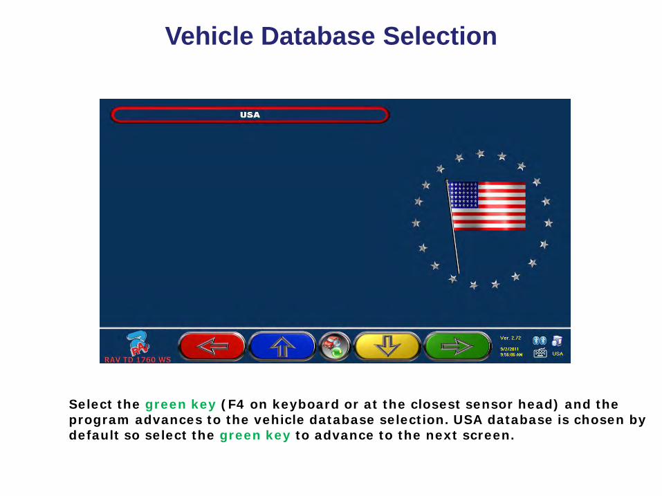
Vehicle Database Selection
Select the green key (F4 on keyboard or at the closest sensor head) and the program advances to the vehicle database selection. USA database is chosen by default so select the green key to advance to the next screen.
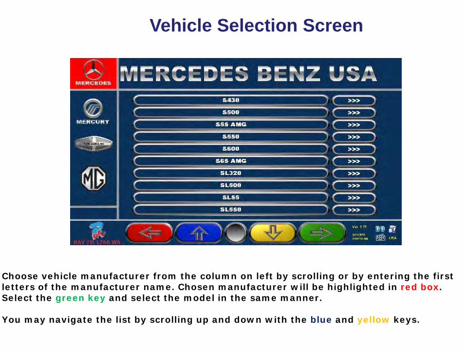
Vehicle Selection Screen
Choose vehicle manufacturer from the column on left by scrolling or by entering the first letters of the manufacturer name. Chosen manufacturer will be highlighted in red box. Select the green key and select the model in the same manner. You may navigate the list by scrolling up and down with the blue and yellow keys.
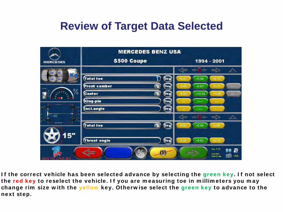
Review of Target Data Selected
If the correct vehicle has been selected advance by selecting the green key. If not select the red key to reselect the vehicle. If you are measuring toe in millimeters you may change rim size with the yellow key. Otherwise select the green key to advance to the next step.

Adjustment Help Images
From the target data review screen any available adjustment images will be identified by the camera icon located on the yellow key. To view these images select the yellow key. Otherwise select the green key to advance.
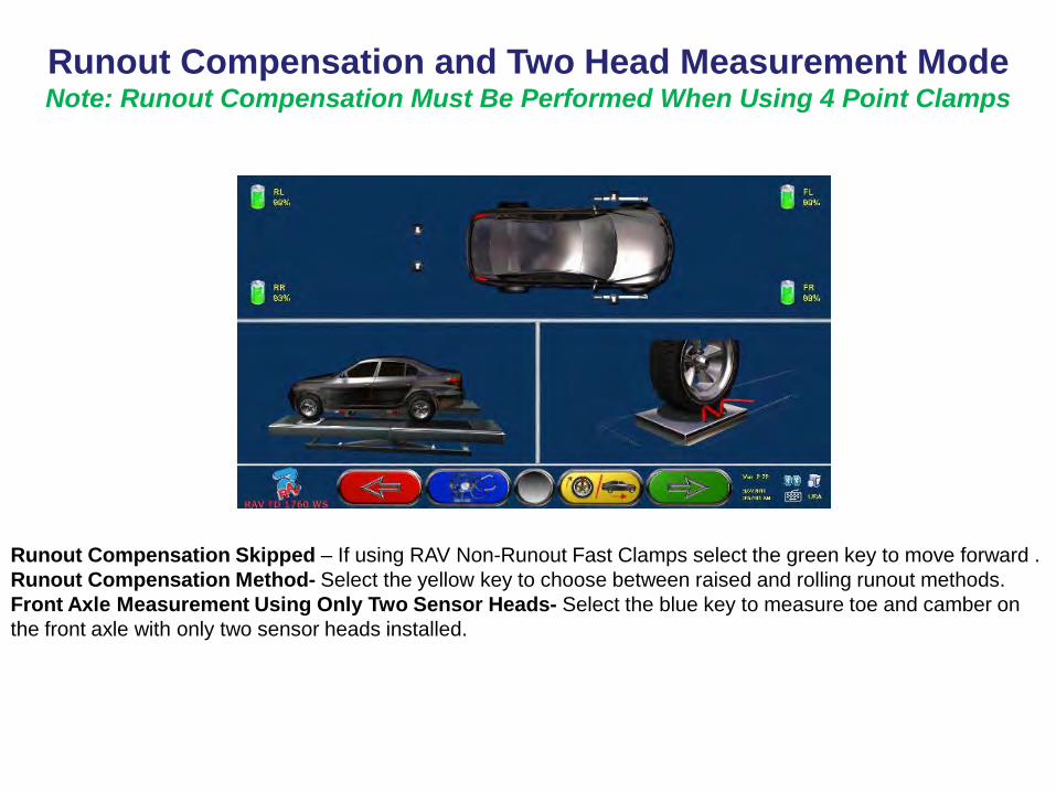
Runout Compensation and Two Head Measurement Mode Note: Runout Compensation Must Be Performed When Using 4 Point Clamps
Runout Compensation Skipped – If using RAV Non-Runout Fast Clamps select the green key to move forward . Runout Compensation Method- Select the yellow key to choose between raised and rolling runout methods. Front Axle Measurement Using Only Two Sensor Heads- Select the blue key to measure toe and camber on the front axle with only two sensor heads installed.

Runout Compensation and Two Head Measurement Mode Note: Runout Compensation Must Be Performed When Using 4 Point Clamps
Runout Compensation Skipped – If using RAV Non-Runout Fast Clamps select the green key to move forward . Runout Compensation Method- Select the yellow key to choose between raised and rolling runout methods. Front Axle Measurement Using Only Two Sensor Heads- Select the blue key to measure toe and camber on the front axle with only two sensor heads installed. Select green key to move forward in the program. Select red key to move backwards in the program.

Runout Compensation in Raised Mode Note: Runout Compensation Must Be Performed When Using 4 Point Wheel Clamps.
If using 4 point wheel clamps you may choose to perform runout compensation in either the raised or the rolling mode. If the raised mode is preferred, raise wheels off runways until they are able to rotate without any interference. Position the wheel at 12 o’clock top dead center. From this screen when the center black key is flashing on screen press that button on the actual head key pad. Rotate the wheel to 6 o’clock position and press center black key again. When center key on screen stops flashing rotate wheel back to 12 o’clock position. Repeat for the other wheels.
This is a 2 postion
runout procedure

Runout Compensation in Rolling Mode Note: Runout Compensation Must Be Performed When Using 4 Point Wheel Clamps
If you have selected to perform runout compensation in the rolling mode roll the vehicle back until the red arrows on screen align. Press the center black key on any head to confirm. Roll the vehicle forward to its original position and press the black key again to confirm. Rolling runout is complete.

Preparations Before Measurement
If you have not done so you should lower the vehicle (if it had been raised), joust the vehicle suspension, unpin the turning plates, and install the brake pedal depressor.

Steer Straight Ahead and Level Heads
Level the front sensor heads until vials on screen are centered and indicate OK with green check marks. Then steer the front wheels in the direction indicated by the arrow on screen until the centering ball icon is in the green area in the center of the bar graph. The STOP sign appears then hold the position steady.

Turning Routine for Caster Measurement
Turn wheels to left until ball and carriage icon is in the green area on the slide. Hold position steady until screen changes. Now turn wheel to the right and repeat. When screen changes steer back to the center until the red stop sign appears.

Review of Collision Angles
Before, during, or after the caster turning routine you may select the yellow key for a review of the vehicle’s chassis geometry. These angles can be helpful in diagnosing improper chassis alignment.

Diagnosis of Rear Axle
Standard View- Details rear axle diagnosis using large bar graphs and vivid red and green colors.
Alternate View- Select the blue key for a different view of the rear axle diagnosis.
Alternate View- Select the center black key on the sensor head or the F5 key on the keyboard for the printout view of the rear axle diagnosis.

Steering Wheel Lock
Install the steering wheel locked with the steering wheel spoke in the straight position. If you intend to use the RAV-TOE procedure for setting front toe you should skip this step.

Adjustment of the Rear Axle Presence of Wrench Icons Indicate a Live Adjustment Screen
Adjust rear angles to preferred targets. Selection of blue key will allow you to view an alternate adjustment screen. Selection of black center key on the sensor head or F5 on the keyboard will allow you to adjust the rear axle while the vehicle is raised.
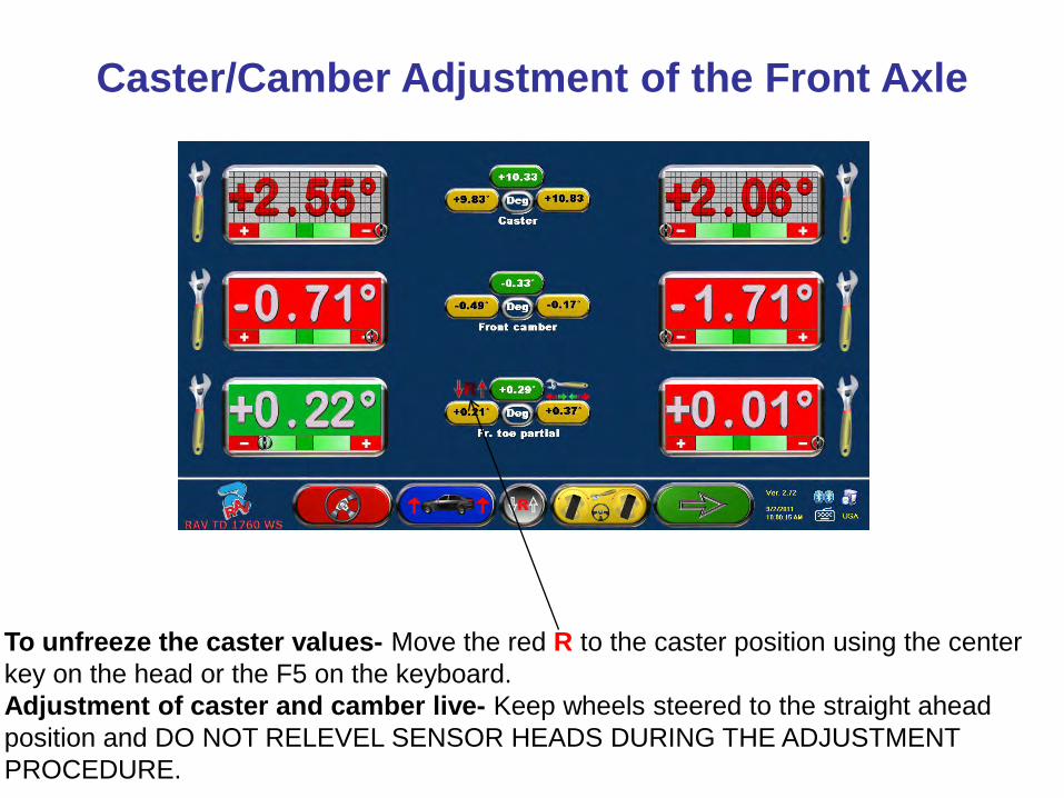
Caster/Camber Adjustment of the Front Axle
To unfreeze the caster values- Move the red R to the caster position using the center key on the head or the F5 on the keyboard. Adjustment of caster and camber live- Keep wheels steered to the straight ahead position and DO NOT RELEVEL SENSOR HEADS DURING THE ADJUSTMENT PROCEDURE.
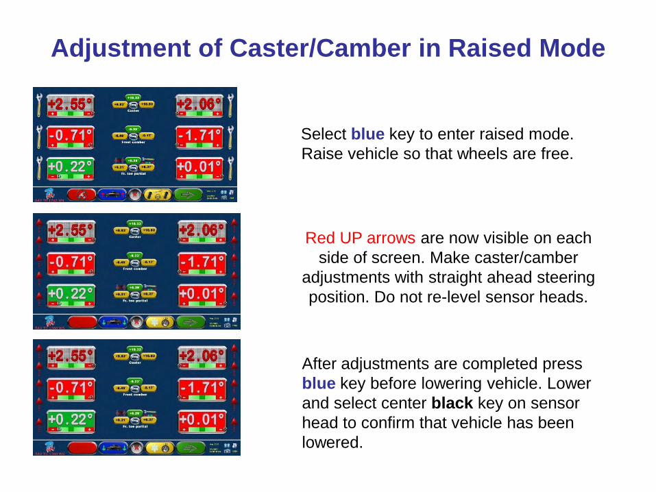
Adjustment of Caster/Camber in Raised Mode
Select blue key to enter raised mode. Raise vehicle so that wheels are free.
Red UP arrows are now visible on each side of screen. Make caster/camber
adjustments with straight ahead steering position. Do not re-level sensor heads.
After adjustments are completed press blue key before lowering vehicle. Lower and select center black key on sensor head to confirm that vehicle has been lowered.

Toe Adjustment on the Front Axle
Adjustment of Partial Toes- With steering wheel lock installed and steering wheel in the straight position set left and right toe to the same value and on preferred specification. Adjustment of Total Toe- With center black key on the head or F5 at the keyboard move the red R to the lower toe position. Select shift/F5 at the keyboard to view the Total Toe adjustment values and graph.

Using RAV-TOE (Setting Toe with Wheels Steered)
Select yellow key to enter RAV-TOE.
Set steering wheel to straight position and confirm with red key.
Select blue key to adjust toe on left wheel.
Adjust toe on left wheel to preferred target.
Select yellow key to adjust toe angle on right .
Adjust toe on left to preferred target. Select
red key to exit.

Review and Additional Measurements
After adjustment of front toe select green key to move forward to the final printout screen.
Final print screen indicates diagnosis, adjustment, and target data values for both axles. Select red key to view additional measurement screen or yellow key to print/store..
When viewing additional measurements use the blue and yellow keys to scroll up or down. Select green to print/store.

Printing and Storing the Alignment Report
If you choose to print/store the report complete the customer information above. To store the report on the system hard drive select the blue key. To print the report select the yellow key. To return to the main screen ready to begin the next alignment select the green key which in this case is HOME.
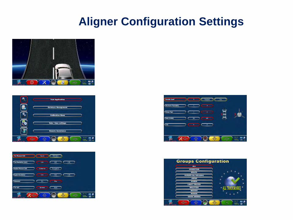
Aligner Configuration Settings