standard procedure - wheel alignment pre-wheel alignment inspection · standard procedure - wheel...
TRANSCRIPT
STANDARD PROCEDURE - WHEEL ALIGNMENT PRE-WHEEL ALIGNMENT INSPECTION Before any attempt is made to change or correct the wheel alignment, the following inspection and necessary corrections must be madeto ensure proper alignment.
1. Verify that the fuel tank is full of fuel. If the tank is not full, the reduction in weight will affect the curb height of the vehicle and thealignment angles. 2. The passenger and luggage compartments of the vehicle should be free of any load that is not factory equipment. 3. Check the tires on the vehicle. All tires must be the same size and in good condition with approximately the same amount of treadwear. Inflate all the tires to the recommended air pressure. 4. Check the front wheel and tire assemblies for excessive radial runout. 5. Inspect lower ball joints and all steering linkage for looseness, binding, wear or damage. Repair as necessary. 6. Check suspension fasteners for proper torque and retighten as necessary. 7. Inspect all suspension component rubber bushings for signs of wear or deterioration. Replace any faulty bushings or componentsbefore aligning the vehicle. 8. Check the vehicle's curb height to verify it is within specifications.
WHEEL ALIGNMENT SETUP 1. Position the vehicle on an alignment rack. 2. Install all required alignment equipment on the vehicle per the alignment equipment manufacturer's instructions. On this vehicle, afour-wheel alignment is recommended.
NOTE: Prior to reading the vehicle's alignment readouts, the front and rear of vehicle should be jounced. Induce jounce (rear first,then front) by grasping the center of the bumper and jouncing each end of vehicle an equal number of times. The bumper should alwaysbe released when vehicle is at the bottom of the jounce cycle.
3. Read the vehicle's current front and rear alignment settings. Compare the vehicle's current alignment settings to the vehiclespecifications for camber, caster and toe-in. 4. If front camber and caster are not within specifications, proceed to CAMBER AND CASTER below. If caster and camber are withinspecifications, proceed to TOE which can be found following CAMBER AND CASTER. Rear camber and caster are not adjustable. Iffound not to be within specifications, reinspect for damaged suspension or body components and replace as necessary. If rear toe is notwithin specifications, adjust rear toe before proceeding to adjust front toe.
CAMBER AND CASTER Camber and caster settings on this vehicle are determined at the time the vehicle is designed, by the location of the vehicle's suspensioncomponents. This is referred to as NET BUILD. The result is no required adjustment of camber and caster after the vehicle is built or whenservicing the suspension components. Thus, when performing a wheel alignment, caster and camber are not normally consideredadjustable angles. Camber and caster should be checked to ensure they meet vehicle specifications. If front camber is found not to meet alignment specifications, it can be adjusted using an available camber adjustment bolt package.Before installing a camber adjustment bolt package on a vehicle found to be outside the specifications, inspect the suspensioncomponents for any signs of damage or bending.
CAUTION: Do not attempt to adjust the vehicles wheel alignment by heating, bending or by performing any other modification to thevehicle's front suspension components or body.
If front camber readings are not within specifications, use the following procedure to install a camber adjustment bolt package, thenadjust front camber.
CAMBER ADJUSTMENT BOLT PACKAGE INSTALLATION The camber adjustment bolt package contains 2 flange bolts, 2 cam bolts, 2 dog bone washers, and 4 nuts. This package services bothsides of the vehicle. Use the package to attach the strut clevis bracket to the steering knuckle after the strut clevis bracket has beenmodified. To install and adjust the camber adjustment bolt package, follow the procedure below.
1. Raise the vehicle until its tires are not supporting the weight of the vehicle. 2. Remove the front tire and wheel assemblies.
CAUTION: When removing the steering knuckle from the strut clevis bracket, do not put a strain on the brake flex hose. Also, do notlet the weight of the steering knuckle assembly be supported by the brake flex hose when removed from the strut assembly. If necessaryuse a wire hanger to support the steering knuckle assembly or if required remove the brake flex hose from the caliper assembly.
CAUTION: The knuckle to strut assembly attaching bolt shanks are serrated and must not be turned during removal. Remove the nutswhile holding the bolts stationary.
Alignment |Service and Repair, Procedures http://repair.alldata.com/alldata/article/display.action?componentId=339...
1 of 12 8/25/2017, 4:29 PM

3. Remove the top and bottom strut clevis bracket-to-steering knuckle attaching bolts (Fig. 7) and discard. Separate the steering knucklefrom the strut clevis bracket and position steering knuckle so it is out of the way of the strut.
Alignment |Service and Repair, Procedures http://repair.alldata.com/alldata/article/display.action?componentId=339...
2 of 12 8/25/2017, 4:29 PM
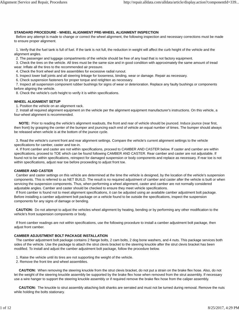
CAUTION: When slotting the bottom mounting hole on the strut clevis bracket, do not enlarge the hole beyond the indentations on thesides of the strut clevis bracket (Fig. 8).
4. Using an appropriate grinder and grinding wheel, slot the bottom hole in both sides of the strut clevis bracket (Fig. 8).
CAUTION: After slotting the strut clevis bracket hole, do not install the original attaching bolts when assembling the steering knuckleto the strut assembly. Only the flange bolts, cam bolts, and dog bone washers from the service package must be used to attach thesteering knuckle to the strut after the mounting hole is slotted.
Alignment |Service and Repair, Procedures http://repair.alldata.com/alldata/article/display.action?componentId=339...
3 of 12 8/25/2017, 4:29 PM

Alignment |Service and Repair, Procedures http://repair.alldata.com/alldata/article/display.action?componentId=339...
4 of 12 8/25/2017, 4:29 PM
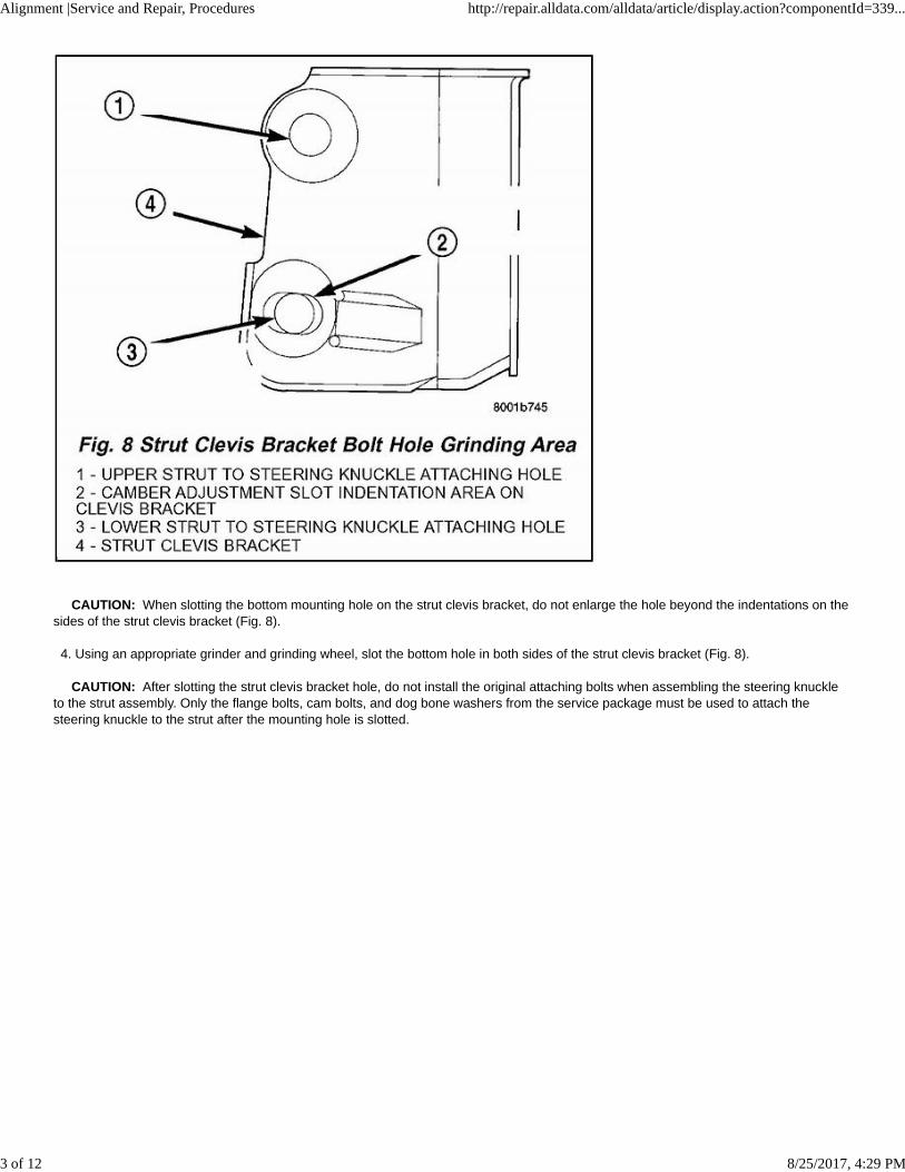
NOTE: The strut clevis-to-knuckle bolts are installed differently on each side of the vehicle. Left-hand-side bolts are installed fromvehicle rear to front (Fig. 9). Right-hand-side bolts are installed from vehicle front to rear (Fig. 10).
Alignment |Service and Repair, Procedures http://repair.alldata.com/alldata/article/display.action?componentId=339...
5 of 12 8/25/2017, 4:29 PM

5. Position the knuckle back into the strut clevis bracket. Using the direction indicated in the above note, install a flanged bolt from theservice package into the upper mounting hole. Using the direction indicated in the above note, install a cam bolt into the bottom mountinghole (Fig. 11).
Alignment |Service and Repair, Procedures http://repair.alldata.com/alldata/article/display.action?componentId=339...
6 of 12 8/25/2017, 4:29 PM

6. Install a dog bone washer on the steering knuckle to strut clevis bracket attaching bolts, then install the nuts onto the bolts from theservice package (Fig. 12). Tighten the bolts just enough to hold the steering knuckle in position when adjusting camber, while still allowingthe steering knuckle to move in clevis bracket. 7. Repeat the procedure to the other side strut clevis bracket. 8. Reinstall both front tire and wheel assemblies and tighten to specifications. 9. Lower the vehicle. Jounce the front and rear of vehicle an equal amount of times.
Alignment |Service and Repair, Procedures http://repair.alldata.com/alldata/article/display.action?componentId=339...
7 of 12 8/25/2017, 4:29 PM
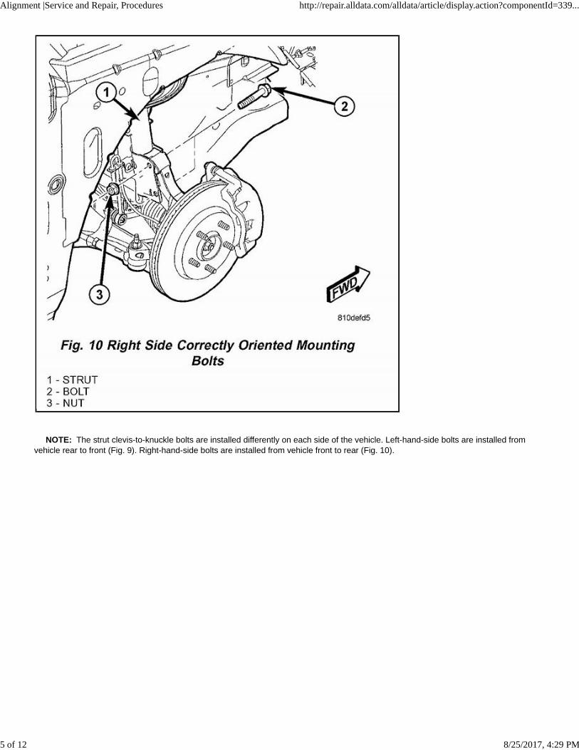
10. Adjust front camber to the preferred setting by rotating the lower eccentric cam bolt against the cam stop areas on the strut clevisbracket (Fig. 13). When camber is set, tighten the upper strut clevis bracket bolt and lower cam bolt. Again jounce front and rear of vehiclean equal amount of times and verify front camber setting. Torque both front strut to steering knuckle attaching bolts to 88 Nm (65 ft. lbs.)plus an additional 1/4 (90°) turn after the required torque is met. 11. If the toe readings obtained are not within the required specification range, adjust toe to meet the preferred specification setting.Proceed to TOE below to set the vehicle's toe.
TOE 1. Center the steering wheel and lock in place using a steering wheel clamp.
NOTE: When performing the toe adjustment procedure, set rear toe to specifications before setting front toe.
REAR TOE
NOTE: Perform the following procedure to each side of the vehicle as necessary.
Alignment |Service and Repair, Procedures http://repair.alldata.com/alldata/article/display.action?componentId=339...
8 of 12 8/25/2017, 4:29 PM

1. Loosen the cam bolt nut securing the toe link to the rear crossmember just enough to rotate the cam bolt (Fig. 14).
NOTE: When adjusting rear toe, the eccentric lobes on the toe adjustment cam bolts and washers are not to be facing downward. Thelobes should only be facing upward or up to 900 to one side or the other from the 12 O'clock position.
Alignment |Service and Repair, Procedures http://repair.alldata.com/alldata/article/display.action?componentId=339...
9 of 12 8/25/2017, 4:29 PM
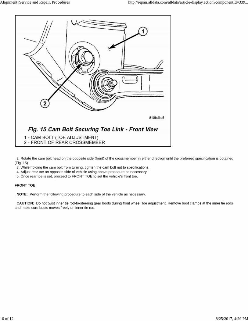
2. Rotate the cam bolt head on the opposite side (front) of the crossmember in either direction until the preferred specification is obtained(Fig. 15). 3. While holding the cam bolt from turning, tighten the cam bolt nut to specifications. 4. Adjust rear toe on opposite side of vehicle using above procedure as necessary. 5. Once rear toe is set, proceed to FRONT TOE to set the vehicle's front toe.
FRONT TOE
NOTE: Perform the following procedure to each side of the vehicle as necessary.
CAUTION: Do not twist inner tie rod-to-steering gear boots during front wheel Toe adjustment. Remove boot clamps at the inner tie rodsand make sure boots moves freely on inner tie rod.
Alignment |Service and Repair, Procedures http://repair.alldata.com/alldata/article/display.action?componentId=339...
10 of 12 8/25/2017, 4:29 PM
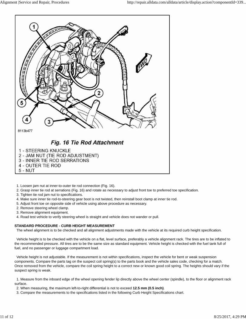
1. Loosen jam nut at inner-to-outer tie rod connection (Fig. 16). 2. Grasp inner tie rod at serrations (Fig. 16) and rotate as necessary to adjust front toe to preferred toe specification. 3. Tighten tie rod jam nut to specifications. 4. Make sure inner tie rod-to-steering gear boot is not twisted, then reinstall boot clamp at inner tie rod. 5. Adjust front toe on opposite side of vehicle using above procedure as necessary. 2. Remove steering wheel clamp. 3. Remove alignment equipment. 4. Road test vehicle to verify steering wheel is straight and vehicle does not wander or pull.
STANDARD PROCEDURE - CURB HEIGHT MEASUREMENT The wheel alignment is to be checked and all alignment adjustments made with the vehicle at its required curb height specification.
Vehicle height is to be checked with the vehicle on a flat, level surface, preferably a vehicle alignment rack. The tires are to be inflated tothe recommended pressure. All tires are to be the same size as standard equipment. Vehicle height is checked with the fuel tank full offuel, and no passenger or luggage compartment load.
Vehicle height is not adjustable. If the measurement is not within specifications, inspect the vehicle for bent or weak suspensioncomponents. Compare the parts tag on the suspect coil spring(s) to the parts book and the vehicle sales code, checking for a match.Once removed from the vehicle, compare the coil spring height to a correct new or known good coil spring. The heights should vary if thesuspect spring is weak.
1. Measure from the inboard edge of the wheel opening fender lip directly above the wheel center (spindle), to the floor or alignment racksurface. 2. When measuring, the maximum left-to-right differential is not to exceed 12.5 mm (0.5 inch). 3. Compare the measurements to the specifications listed in the following Curb Height Specifications chart.
Alignment |Service and Repair, Procedures http://repair.alldata.com/alldata/article/display.action?componentId=339...
11 of 12 8/25/2017, 4:29 PM

CURB HEIGHT SPECIFICATIONS
© 2017 ALLDATA, LLC. All Rights Reserved. (Version 2.0.13872)
Alignment |Service and Repair, Procedures http://repair.alldata.com/alldata/article/display.action?componentId=339...
12 of 12 8/25/2017, 4:29 PM

CURB HEIGHT
WHEEL ALIGNMENT
NOTE: All specifications are given in degrees.
NOTE: All wheel alignments are to be set at curb height.
© 2017 ALLDATA, LLC. All Rights Reserved. (Version 2.0.13872)
Alignment |Specifications, Mechanical http://repair.alldata.com/alldata/article/display.action?componentId=339...
1 of 1 8/25/2017, 4:30 PM