all margin roeen an ncreae reure aio in tranonic aial
TRANSCRIPT

AUT Journal of Mechanical Engineering
AUT J. Mech. Eng., 4(1) (2020) 3-16DOI: 10.22060/ajme.2019.14840.5746
Stall Margin Improvement and Increase Pressure Ratio in Transonic Axial Compressor Using Circumferential Groove Casing TreatmentA. Jafar Gholi Beik1*, S. H. Torabi2, H. Basirat Tabrizi3
1 Mechanical Engineering Department, Jundi-Shapur University of Technology, Dezful, Iran2 Aerospace Engineering Department, Khajeh Nasir Toosi University of Technology, Tehran, Iran3 Mechanical Engineering Department, Amirkabir University of Technology, Tehran, Iran
ABSTRACT: Maximum pressure ratio and aerodynamic blades loading are the most important factors in designing axial compressor restricted by minimum airflow. The present work aims to stall margin and total pressure ratio in transonic axial compressor using circumferential groove casing treatment (CGCT). In the first step, untreated compressor was simulated, compared, and agreed well with the experimental data. Then the treated rotor was simulated and results indicated that using CGCT improves the stall margin and increases the rotor pressure ratio. Stall margin was improved by 8% and the pressure ratio before stall condition and at the design point increased by 2.6% and 2.8 %, respectively. Additionally, it replaces normal shock with oblique shock near instability, causing less total pressure drop, moreover, the oblique shocks occurrence restricts separation zones and assists the rotor to perform far from instability. Furthermore, axial speed passing through rotor in a certain mass flow increases by 15 m/s, and then kinetic energy and stability increased. However, total efficiency of rotor reduces near 1%. In the last step, engine was analyzed with the aid of cycle analysis and leads to 62kW increase in shaft power as well as 1.87 g/kNs less fuel consumption due to 2.8% increase in the rotor pressure ratio.
Review History:
Received: 17 Aug. 2018Revised: 17 Nov. 2018Accepted: 3 Dec. 2018Available Online: 6 Apr. 2019
Keywords:
Transonic axial compressor,
circumferential groove casing treat-
ment,
stall margin,
efficiency
3
1- IntroductionAs minimum air flow poses a restriction in designing axial
compressor especially essential its factors such as maximum pressure ratio and blades loads. Decrease in airflow to less than design point; makes stable and symmetric flow unstable. The instability is observed in the two kinds of rotating stall and surge. Rotation stall refers to a local phenomenon, which stalled cells rotate on the compressor annulus due to loss in required energy and static pressure passing through downstream flow. Significant decrease in efficiency and pressure ratio is followed by rotating stall, but the surge phenomenon as a global instability can completely shut down the compressor in the initial steps if it does not return to the stall conditions. Furthermore, it causes severe blades vibration and fatigue due to the thermal and mechanical blade loads [1,2]. Thus, aerodynamic performance improvement of axial compressor, especially around stall point is an assistance to increase the compressor stability.
Various experimental and numerical studies have been conducted to find the mechanism, which caused the instability inception. Adamczyk et al. [3] explored the role of tip clearance in high-speed fan stall and reported that simulation showed that the interaction of the tip leakage vortex and the in-passage shock plays a major role in determining the fan flow range. Hoying et al. [4] investigated the role of blade passage flow structures in axial compressor rotating stall inception.
They found the movement of the tip clearance vortex forward of the leading edge depends upon local flow phenomena. Related to the tip clearance with the implication that for this and possibly other stall mechanisms the flow structure within the blade passages must be addressed to explain the stability of an axial compression system that exhibits such short length-scale disturbances. Wilke and Kau [5] described the impact of axial slots on the flow field in a transonic rotor blade row. They proposed a modified Casing Treatment (CT) configuration, which stabilizes the tip leakage vortex and reduces the influence on the flow inside the blade passage. Vo et al. [6] conducted a computational study to define the phenomena leading to the onset of short length-scale (spike) rotating stall disturbances. They indicated necessity of two conditions for the formation of spike disturbances in unsteady simulation, both of which were connected to the tip clearance flow. The first condition was that the interface between the tip clearance and oncoming flows becomes parallel to the leading edge plane. The second condition was concerned with the initiation of backflow, stemming from the fluid in adjacent passages, at the trailing edge plane. Hah et al. [7] reported studies on advancing the understanding of the flow mechanism leading to the onset of short-length scale rotating stall in a transonic axial compressor. In their studies, they indicated that the spike-type rotating stall developed when the passage shock was fully detached from the blade passages. Interaction between the tip clearance vortex and the passage shock resulted in creating a low momentum area near the blade pressure side. This low momentum area *Corresponding author’s email: [email protected]
Copyrights for this article are retained by the author(s) with publishing rights granted to Amirkabir University Press. The content of this article
is subject to the terms and conditions of the Creative Commons Attribution 4.0 International (CC-BY-NC 4.0) License. For more information, please visit https://www.creativecommons.org/licenses/by-nc/4.0/legalcode.

A. Jafar Gholi Beik et al.,AUT J. Mech. Eng., 4(1) (2020) 3-16, DOI: 10.22060/ajme.2019.14840.5746
4
moves further upstream and reversed tip clearance flow was initiated at the trailing edge plane when the mass flow rate decreases. Finally, forward spillage of the tip clearance flow occurred and the low momentum area near the pressure side reached the leading edge. Davis and Yao [8] conducted numerical and experimental research of stall inception on subsonic axial-flow compressor rotor. They examined three-dimensional flow simulation, and blade tip high-response static pressure measurements were performed on an isolated subsonic compressor rotor to further investigate the stall inception mechanism of the compressors; the results indicated that the tip leakage vortex dissipation and shedding became violent as the compressor approached the Near Stall (NS) condition. Consequently, the shedding or dissipated flow structures would scatter around the blade tip passage, forming the initial onset of stall disturbances. These scattered vortexes finally led to compressor stall as they collided and merged with each other into low-frequency disturbance of significant energy and size. Huh et al. [9] studied the flow characteristics in a transonic axial compressor operating only before stall inception. Experimental data demonstrated large oscillations associated with the tip clearance vortex near the stall condition. Through analyzing measured wall pressure, a dominant frequency component that can be interpreted as a precursor of stall inception was identified. To analyze and identify this phenomenon, computational studies based on full annulus and a single passage were conducted. The unsteady motion of tip clearance vortices considerably affected the flow field in a transonic compressor near stall. Accordingly, Large Eddy Simulation (LES) was conducted to capture the tip clearance vortex structure more realistically. When the rotor operated near stall, the wall pressure spectrum of this numerical analysis also depicted a dominant frequency. Lu et al. [10] studied the stability-limiting flow mechanism close to stall, being the basic knowledge required to manipulate end-wall flow behavior to improve the stability. In addition to the flow instability manipulation with casing treatment, the primary stall margin enhancement afforded by end-wall treatments was founded to be result of the tip flow manipulation. In comparison to the smooth wall case, the treated casing considerably dampened or absorbed the blockage near the upstream part of the blade passage caused by the upstream movement of tip clearance flow, weakening the roll-up of the core vortex. These mechanisms delayed the onset of flow instability and prevented an early spillage of low momentum fluid into the adjacent blade passage. Therefore, the physic of complex flow related to end-wall flow, particularly tip clearance resulting in tip leakage flow is viewed as one of the significant parameters in starting flow instability. The most efficient methods to prevent and delay the occurrence of instabilities phenomenon is a common question for researchers, which is not fully answered yet.
Today, several methods introduced which use enhancements to the stator performance to solve the stability increase of the compressor. They are divided into active and passive methods. Passive methods encompass creating different casing treatments configurations: grooves, honeycomb seals, etc. Most recent research focused on the passive control, end-wall flow, and casing treatment around tip of the blade of rotating part in order to increase the aerodynamic loads and efficiency. Shabbir and Adamczyk [11] conducted a study to clarify the role of the physical mechanism in improving stall margin of a
low-speed axial flow rotor owing to the circumferential casing grooves. Computational fluid dynamics simulations indicated an increase in the operating range of the low-speed rotor in the presence of casing grooves. It was indicated that the net axial shear stress force for the smooth casing balances the net axial pressure force at the rotor casing in the tip gap. However, for the grooved casing, the net axial shear stress force acting at the casing was augmented by the axial force due to the radial transport of axial momentum occurring across the grooves and power stream interface. This extra force adds to the net axial viscous shear force, thereby leading to an increase in the rotor stall margin. Lu et al. [12] experimentally and numerically investigated the stepped tip gap effects on a subsonic axial-flow compressor rotor; they experimentally demonstrated that the inclusion of stepped tip gaps with the small clearance level gave increased efficiency, pressure ratio, and stall margin throughout the mass flow range at both speeds. Moreover, the numerical procedure correctly predicted the overall effects of stepped tip gaps. Detailed results of numerical simulation indicated that the interaction between the blade passage flow and the stepped groove flow could entrain the blockage produced by upstream tip leakage flow into the tip gap of adjacent blades of the compressor rotor. Wilke et al. [13] studied numerically the flow mechanisms resulting in compressor stall in design and off-design conditions. The conducted numerical simulations demonstrated that at design speed, the tip leakage flow behavior in combination with the angle of attack at the blade tips was the crucial factor limiting the flow stability. While at off-design, a steep angle of attack near the blade tip created vast flow separations on the suction side of the blade and additionally, they designed an adapted casing treatment for the NASA Rotor 37. Lu et al. [14] investigated mechanism of the interaction between tip leakage flow and casing treatment in a subsonic axial compressor. They, through rotor blade passages, provided detailed steady and unsteady numerical studies of the coupled flow and two different types of casing treatment for a modern subsonic axial-flow compressor rotor. They also found that the primary stall margin enhancement afforded by the casing treatment was a result of the tip clearance flow manipulation. Delaying the movement of incoming/tip clearance flow interface to the leading edge plane and further repositioning of the tip clearance vortex toward the trailing edge of the blade passage were the physical mechanisms responsible for extending the compressor stall margin. Lu et al. [15] examined experimentally and numerically the steady micro-tip injection on a subsonic axial-flow compressor rotor and provided a design for the tip injection through the casing with flush-mounted inclined holes and the effectiveness of steady micro-air injection in order to improve stability in a subsonic axial-flow compressor rotor by an external-air supply. Further Lu et al. [16] numerically and experimentally examined a subsonic compressor using bend skewed slot casing treatment. They designed a new casing treatment type for a subsonic axial flow compressor rotor through optimization of different geometry parameters according to the test results of discrete axial and blade angle slot casing treatment. The results indicated that significant improvements in stall margin were possible in all exposures and insignificant isentropic efficiency sacrifices were recorded in some exposures. The numerical results were shown in good agreement with
A. Jafar Gholi Beik et al.,AUT J. Mech. Eng., 4(1) (2020) 3-16, DOI: 10.22060/ajme.2019.14840.5746
5
experimental results. Detailed analyses of the coupled flow through bend skewed slot casing treatment and rotor blade passage under subsonic conditions led to some preliminary conclusions as to the flow physics involved in the stall margin improvements afforded by using bend skewed slot casing treatment. Ghila and Tourlidakis [17] investigated by simulating different kinds of casing treatments above the rotor blades, which reduced the tangential component of velocity (V θ ), increased axial component of velocity ( axialV ) of compressor and removed blockage of the blade tip of rotor. Emmrich et al. [18] experimentally studied a casing treatment with axial and radial skewed slots ending in a plenum chamber at highly subsonic axial compressor stage. The experimentally gained performance results of this configuration demonstrated an extension of the operating range by about 50%, whereas the efficiency for design conditions was decreased by 1.4%. Muller et al. [19] investigated effect of circumferential grooves on the aerodynamic performance of an axial single-stage transonic compressor. They reported that total pressure ratio and efficiency speed lines were considered in design speed and three off-design conditions. The experiments consisted of four different configurations with deep and shallow grooves and variable coverage of the projected rotor axial chord. All casing treatments were proved to have a constructive effect on stall range while keeping high levels of efficiency, even at off-design operation. Deep grooves extending almost to the trailing edge indicated the biggest potential: the mass flow at stall inception for design speed could be highly reduced, and half could enlarge the operating range. Jian and Hu [20] studied numerically inlet distortion on an axial flow compressor rotor with Circumferential Groove Casing Treatment (CGCT). In their study, they demonstrated that the circumferential groove casing treatment could expand the operating range of the compressor rotor either with or without inlet pressure distortion at the expense of drop in peak isentropic efficiency. The casing treatment can weaken and even remove the tip leakage vortex effectively either with or without inlet distortion. In clean inlet circumstances, the enhancement and forward movement of tip leakage vortex caused the untreated compressor rotor to stall. In contrast to circumferential groove casing, the serious flow separation on the suction surface eventually resulted in aerodynamic stalling. Dong et al. [21] conducted an experimental study of a Stall Precursor-Suppressed (SPS) casing treatment with air suction or blowing air. The SPS casing treatment was designed to suppress stall precursors to realize stall margin enhancement in turbomachinery. The results showed that the casing treatment with blowing air of small quantity could enhance the stall margin by approximately 8% with approximately 1% efficiency loss. On the other hand, the SPS casing treatment with micro-bias flow did not enhance the stall margin much more than that without bias flow, even worse. Taghavi-Zenouz and Abbasi [22] investigated application of grooved type casing treatment to suppress spike stall in an isolated axial compressor rotor blade row. Their results concluded that the casing treatment of the stepped tip gap type could increase the compressor stall margin. This fact is owing to retarding the movement of the interface region between incoming and tip leakage flows toward the rotor leading edge plane and suppressing the reversed flow around the blade trailing edge. Li et al. [23] examined influence of SPS casing treatment on axial flow
compressor exposed to radial pressure distortion. Experimental research was conducted on a low-speed compressor with and without SPS casing treatment at radial distorted inlet flow of different levels and uniform inlet flow. Their results indicated that the radial inlet distortion could cause a stall margin loss from 2% to 30% at different distorted levels. The SPS casing treatment could compensate for this stall margin loss at small distortion level and only partly remedy the stall margin loss caused by distortion at large level without leading to perceptible additional efficiency loss and obvious change of characteristic curves. Furthermore, Xue et al. [24] investigated mechanism of stall and surge in a centrifugal compressor with a variable vanned in order to extend the stable operating range of compressors. They offered a specific indicator to measure the instability of each component in a compressor. The indicator can be applied to determine the best region for stability extension technologies like a holed casing treatment, in various compressor applications.
Casing treatment, with the aid of attenuating the rotation of vortex core, prevents early leakage of flow with low momentum into passage of adjacent blade, and then delays the start of instability [25]. It was useful especially when the tip of rotor is prone to stall [26]. It was evident that CTs can improve stall margin; however, usually decrease efficiency of compressor. This research tries to use a modified passive control to prevent instability phenomenon so that stall margin and maximum pressure ratio can be increased. Finally, analysis of improvement in shaft power and fuel consumption will be shown.
2- Experimental Investigation and Numerical Modeling2- 1- Investigation of the casing and compressor
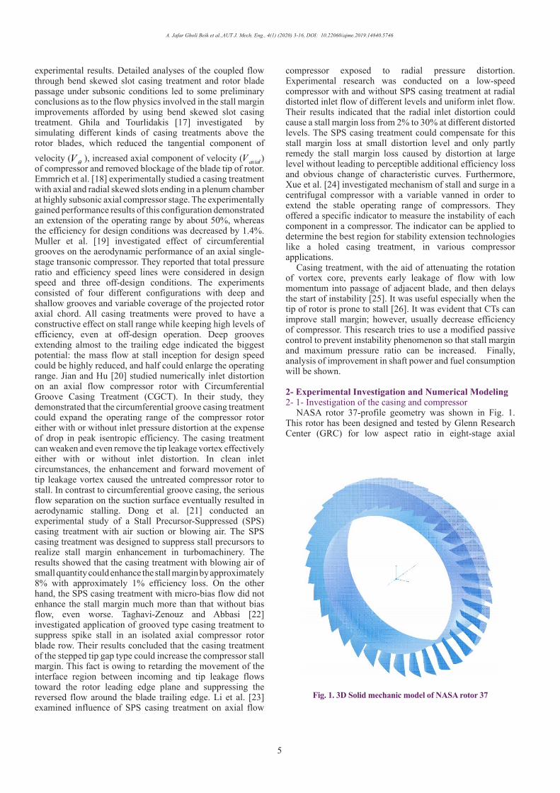
NASA rotor 37-profile geometry was shown in Fig. 1. This rotor has been designed and tested by Glenn Research Center (GRC) for low aspect ratio in eight-stage axial
1
Fig. 1. 3D Solid mechanic model of NASA rotor 37
A. Jafar Gholi Beik et al.,AUT J. Mech. Eng., 4(1) (2020) 3-16, DOI: 10.22060/ajme.2019.14840.5746
6
compressor with 20.2 pressure ratio. Table 1 shows the main design parameters. This rotor was tasted individually, and the obtained data were used in this research. Table 1 summarizes the operational and geometric characteristics of NASA 37 [27].
Design parameters and experimental data were taken from the NASA report [27, 28] to model in BladeGen [29] (See Fig. 1)
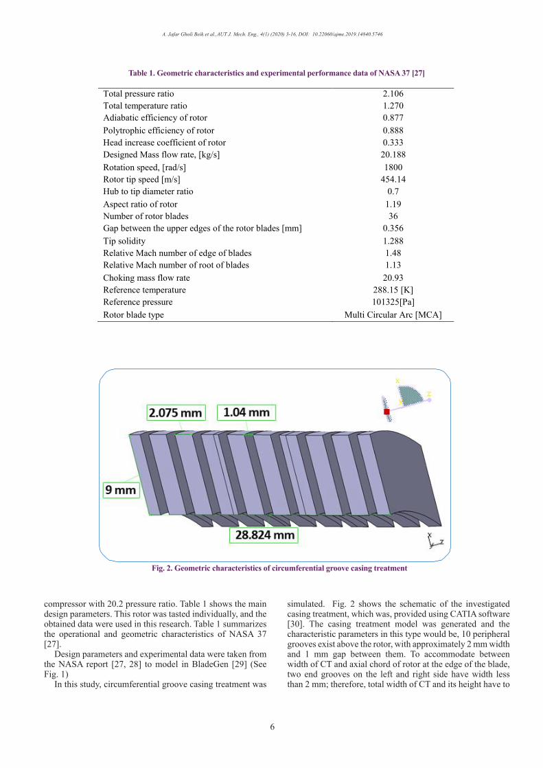
In this study, circumferential groove casing treatment was
simulated. Fig. 2 shows the schematic of the investigated casing treatment, which was, provided using CATIA software [30]. The casing treatment model was generated and the characteristic parameters in this type would be, 10 peripheral grooves exist above the rotor, with approximately 2 mm width and 1 mm gap between them. To accommodate between width of CT and axial chord of rotor at the edge of the blade, two end grooves on the left and right side have width less than 2 mm; therefore, total width of CT and its height have to
1
Total pressure ratio 2.106 Total temperature ratio 1.270 Adiabatic efficiency of rotor 0.877 Polytrophic efficiency of rotor 0.888 Head increase coefficient of rotor 0.333 Designed Mass flow rate, [kg/s] 20.188 Rotation speed, [rad/s] 1800 Rotor tip speed [m/s] 454.14 Hub to tip diameter ratio 0.7 Aspect ratio of rotor 1.19 Number of rotor blades 36 Gap between the upper edges of the rotor blades [mm] 0.356 Tip solidity 1.288 Relative Mach number of edge of blades 1.48 Relative Mach number of root of blades 1.13 Choking mass flow rate 20.93 Reference temperature 288.15 [K] Reference pressure 101325[Pa] Rotor blade type Multi Circular Arc [MCA]
Table 1. Geometric characteristics and experimental performance data of NASA 37 [27]
2
Fig. 2. Geometric characteristics of circumferential groove casing treatment

A. Jafar Gholi Beik et al.,AUT J. Mech. Eng., 4(1) (2020) 3-16, DOI: 10.22060/ajme.2019.14840.5746
7
be 28.824 and 9 mm, respectively.
2- 2- SimulationThe simulation was conducted based on the transonic
axial flow compressor stage for The NASA rotor 37 using ANSYS-CFX software [29] in a steady state process. At first, untreated compressor was simulated in this research, and simulation results were compared with experimental data. Then the performance of casing treatment and its impact on performance curve of treated rotor as well as efficiency of rotor NASA 37 were simulated. Thirdly, time scale as an important parameter in stable and unstable simulation supposed to be 1
ω for a steady state, which ω is rotation speed. Next, k ω− turbulence closure model was selected and converging criteria for maximum remain in each step were chosen 10e-4. Note that, it did not converge when it is close to the stall point while reducing mass flow and increasing backpressure.
2- 2- 1- Boundary conditionFirst, working fluid was considered as ideal gas. Second,
no heat transfer and no slip boundary condition were
applied. Third, Periodic boundary condition was chosen in order to make it possible to simulate a single blade of rotor. Additionally, in boundary condition, total pressure and total temperature were chosen as inlet to blades and static pressure as output condition. Finally, Total inlet pressure and temperature were taken 101325 Pa and 288.15 K, respectively.
2- 2- 2- Meshing descriptionA structured meshing was constructed using the ANSYS
TurboGrid [29]. Then, surrounding of the blade, other part of the blade, and casing treatment were meshed by O, H and hexagonal type, respectively and mesh independency studies was conducted. In this respect, different size of meshing was evaluated until no considerable variations in the results were observed for different mesh structures consisting of a total number of cells exceeding 1.5. In this case, the mesh density near the solid walls was ensured the y+ values, which enabled the viscous sub-layer to be resolved precisely, to be kept at less than 10. Figs. 3(a) and 3(b) present views of grid generated for rotor and casing treatment, and Fig. 4 shows that solving the area includes rotor and CT with the aid of periodic solving, making it possible to simulate one-thirty
3
Fig. 3. (a) Structured Meshing on NASA 37 rotor (b) Meshing on casing treatment

A. Jafar Gholi Beik et al.,AUT J. Mech. Eng., 4(1) (2020) 3-16, DOI: 10.22060/ajme.2019.14840.5746
8
sixth (1/36) of total domain the same as that of the rotor.
2- 3- Stall margin and pressure ratio calculationTo calculate improvement of stall margin and pressure
ratio in axial compressor, Eq. (1) is used [31]:
1
.12
11
.2 1
1 1
1
oo
oo Desigpoinstall
o o
o oDesigpoin Stall
TP mPP
P TmP P
(1)
where 02
01 stall
PP
, 01 02 01
01 01 01, and
DesignpointStall Designpoint
T P Tm mP P P
are the pressure ratio and modified mass flow at stall point and design point, respectively. The amount of increase in pressure ratio is calculated by:
2
Pressure Ratio increase 2 1
1
100P PP
(2)
(2)
2- 4- Stage parametersThe adiabatic efficiency is the ratio of the actual energy
output to the theoretical isentropic output for same input total state and same exit total pressure:
3
02 01
02 01
100ts
h hh h
(3)
(3)
For the calorically perfect gas, the efficiency can be written in terms of total temperature and total pressure as Eq. (4). The preceding definition is sometimes called the total-to-total efficiency, since the total output is based on the leaving total pressure [32]:
4
02 0102 01
02 01 02 01
100 100p t tTT
s p t s t
c T Th hh h c T T
(4)
(4)
where h02, h01, Tt01 and Tt02 are secondary and initial actual enthalpy per unite mass and total temperature, h02s and Tt02s are isentropic enthalpy per unite mass and total isentropic temperature. In similar way for static-to-static efficiency:
5
2 1
2 1
100sSS
h hh h
(5)
(5)
where h2 and h1 are secondary and initial actual enthalpy per unite mass, and h2s isentropic enthalpy per unite mass.
3- Results and Discussions3- 1- Modeling without casing treatment at design point
First, simulation was conducted at design point (according to Table 1). For this purpose, the total pressure and total temperature were selected 101325 Pa and 288.15 K, respectively at inlet of rotor, and outlet static pressure was changed until designed pressure ratio, 2.106, was obtained. Table 2 summarizes the results.
According to Table 2, close agreement between experimental and numerical results was observed, which
4
Fig. 4. Solving domain includes NASA 37 and casing treatment

A. Jafar Gholi Beik et al.,AUT J. Mech. Eng., 4(1) (2020) 3-16, DOI: 10.22060/ajme.2019.14840.5746
9
the maximum difference increased to mass flow rate by 2.3 %. Fig. 5 shows mesh independency for total pressure ratio and total to total isentropic efficiency. It is evident that no considerable variations in the results were observed for cell numbers exceeding 15000000 or for y+ less than 10. Consider the experimental and simulated results shown in Table 2 which include average of thermodynamic parameters, e.g. pressure ratio indicates ratio of average pressure in outlet surface to average pressure in inlet surface.
Figs. 6 and 7 illustrate comparison of simulation with the experimental data of [27] for the total temperature and pressure ratio according to dimensionless height from root to tip (zero in this scale indicates root and 100 shows tip) in the output of the rotor for experimental and numerical, which are in good agreement, while the average amounts are mentioned. Note that in the practical survey for measuring temperature and pressure ratio; sensors should be installed with a small gap far from the casing wall to expose to the main stream flow, while in the numerical study this is easily achievable to analyze temperature and pressure ratio exactly near the wall with negligible gap. Therefore, No Slip boundary condition may result in abrupt changes in simulated dynamic terms.
In addition, sudden change in pressure ratio caused by local reverse flow in this zone.
Fig. 8 compares experimental and numerical mass flow rate against the total pressure ratio of NASA 37, which clearly shows good agreement between results. Choked mass flow rate showed on the right side of Fig. 8 is 20.93 and 20.914 kg/s for experimental and numerical respectively, which means negligible, difference approximately 0.07%. In addition, vertical shape of the curve on the right side of Fig. 8 confirms that mass flow rate remained constant during the pressure ratio changes. On the left side of the curve, it shows that increasing in output static pressure caused decreasing in mass flow rate; however, a remarkable increase was not observed in the total pressure ratio and rotor became unstable while mass flow reduced.
Fig. 9 shows the efficiency curve based both experimental and numerical results that draws the mass flow rate against total to total efficiency (see Eq. (3)). As shown in Fig. 9, the difference between experimental and numerical efficiency against mass flow rate which is not more than 2.3% except in the choked region, and a good agreement can be noticed.
2
Parameters Simulated results Percentage difference with experimental results of [27]
Total rotor pressure ratio 2.106 0 Total rotor temperature ratio 1.27058 0.4% Adiabatic efficiency of rotor 0.8632 1.5% Polytrophic efficiency of rotor 0.8763 1.4% Head increase coefficient of rotor 0.334 0.3% Designed Mass flow rate kg/s 20.66 2.3%
Table 2. Output parameters of numerical modeling at design point
5
2.1055
2.106
2.1065
2.107
2.1075
2.108
0.862
0.864
0.866
0.868
0.87
0.872
0.874
0.876
0.878
0.88
0 250000 500000 750000 1000000 1250000 1500000 1750000 2000000
Tota
l to
tota
l ise
ntro
pic
effic
ienc
y
Tota
l pre
ssur
e ra
tio
Number of Elements
Total pressure ratio
Total to total isentropic efficiency
Fig. 5. Mesh independency

A. Jafar Gholi Beik et al.,AUT J. Mech. Eng., 4(1) (2020) 3-16, DOI: 10.22060/ajme.2019.14840.5746
10
6
0
10
20
30
40
50
60
70
80
90
100
1.22 1.23 1.24 1.25 1.26 1.27 1.28 1.29 1.3 1.31 1.32
Span
Nor
mal
ized
Total Tempreture Ratio
Numerical Data
Experimental Data [27]
7
0
10
20
30
40
50
60
70
80
90
100
1.8 1.85 1.9 1.95 2 2.05 2.1 2.15 2.2
Span
Nor
mal
ized
Total Pressure Ratio
Numerical Data
Experimental Data [27]
Fig. 6. Total temperature ratio at design point without casing treatment
Fig. 7. Total pressure ratio at design point without casing treatment

A. Jafar Gholi Beik et al.,AUT J. Mech. Eng., 4(1) (2020) 3-16, DOI: 10.22060/ajme.2019.14840.5746
118
1.875
1.9
1.925
1.95
1.975
2
2.025
2.05
2.075
2.1
2.125
2.15
2.175
18.6
18.7
18.8
18.9 19
19.1
19.2
19.3
19.4
19.5
19.6
19.7
19.8
19.9 20
20.1
20.2
20.3
20.4
20.5
20.6
20.7
20.8
20.9 21
21.1
21.2
Tota
l Pre
ssur
e Ra
tio
mass flow rate [kg/s]
Experimental data [27]
Numerical data
9
0.8
0.81
0.82
0.83
0.84
0.85
0.86
0.87
0.88
0.89
0.9
19 19.2 19.4 19.6 19.8 20 20.2 20.4 20.6 20.8 21 21.2
tota
l to
tota
l ise
ntro
pic
effic
ieny
mass flow rate [kg/s]
Experimental data [27]
Numerical data
Fig. 8. Performance curve of NASA 37 without casing treatment
Fig. 9. Total to total isentropic efficiency without casing treatment
A. Jafar Gholi Beik et al.,AUT J. Mech. Eng., 4(1) (2020) 3-16, DOI: 10.22060/ajme.2019.14840.5746
12
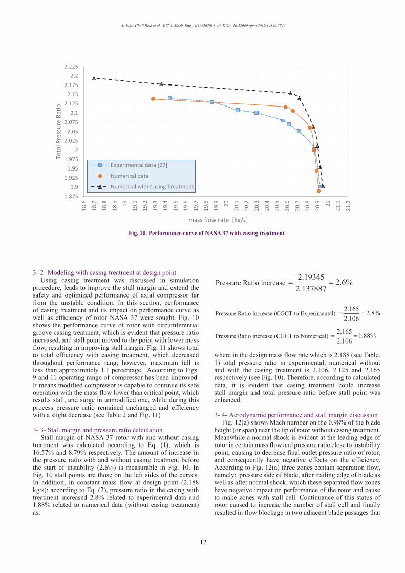
3- 2- Modeling with casing treatment at design pointUsing casing treatment was discussed in simulation
procedure, leads to improve the stall margin and extend the safety and optimized performance of axial compressor far from the unstable condition. In this section, performance of casing treatment and its impact on performance curve as well as efficiency of rotor NASA 37 were sought. Fig. 10 shows the performance curve of rotor with circumferential groove casing treatment, which is evident that pressure ratio increased, and stall point moved to the point with lower mass flow, resulting in improving stall margin. Fig. 11 shows total to total efficiency with casing treatment, which decreased throughout performance rang; however, maximum fall is less than approximately 1.1 percentage. According to Figs. 9 and 11 operating range of compressor has been improved. It means modified compressor is capable to continue its safe operation with the mass flow lower than critical point, which results stall, and surge in unmodified one, while during this process pressure ratio remained unchanged and efficiency with a slight decrease (see Table 2 and Fig. 11)
3- 3- Stall margin and pressure ratio calculationStall margin of NASA 37 rotor with and without casing
treatment was calculated according to Eq. (1), which is 16.57% and 8.79% respectively. The amount of increase in the pressure ratio with and without casing treatment before the start of instability (2.6%) is measurable in Fig. 10. In Fig. 10 stall points are those on the left sides of the curves. In addition, in constant mass flow at design point (2.188 kg/s); according to Eq. (2), pressure ratio in the casing with treatment increased 2.8% related to experimental data and 1.88% related to numerical data (without casing treatment) as:
6
2.19345 2.6%2.137887
Pressure Ratio increase
2.165 2.8%2.106
(CGCT to Experimental) Pressure Ratio increase
2.165 1.88%2.106
Pressure Ratio increase (CGCT to Numerical)
6
2.19345 2.6%2.137887
Pressure Ratio increase
2.165 2.8%2.106
(CGCT to Experimental) Pressure Ratio increase
2.165 1.88%2.106
Pressure Ratio increase (CGCT to Numerical)
where in the design mass flow rate which is 2.188 (see Table. 1) total pressure ratio in experimental, numerical without and with the casing treatment is 2.106, 2.125 and 2.165 respectively (see Fig. 10). Therefore, according to calculated data, it is evident that casing treatment could increase stall margin and total pressure ratio before stall point was enhanced.
3- 4- Aerodynamic performance and stall margin discussionFig. 12(a) shows Mach number on the 0.98% of the blade
height (or span) near the tip of rotor without casing treatment. Meanwhile a normal shock is evident at the leading edge of rotor in certain mass flow and pressure ratio close to instability point, causing to decrease final outlet pressure ratio of rotor, and consequently have negative effects on the efficiency. According to Fig. 12(a) three zones contain separation flow, namely: pressure side of blade, after trailing edge of blade as well as after normal shock, which these separated flow zones have negative impact on performance of the rotor and cause to make zones with stall cell. Continuance of this status of rotor caused to increase the number of stall cell and finally resulted in flow blockage in two adjacent blade passages that
10
1.8751.9
1.9251.95
1.9752
2.0252.05
2.0752.1
2.1252.15
2.1752.2
2.225
18.6
18.7
18.8
18.9 19
19.1
19.2
19.3
19.4
19.5
19.6
19.7
19.8
19.9 20
20.1
20.2
20.3
20.4
20.5
20.6
20.7
20.8
20.9 21
21.1
21.2
Tota
l Pre
ssur
e Ra
tio
mass flow rate [kg/s]
Experimental data [27]
Numerical data
Numerical with Casing Treatment
Fig. 10. Performance curve of NASA 37 with casing treatment

A. Jafar Gholi Beik et al.,AUT J. Mech. Eng., 4(1) (2020) 3-16, DOI: 10.22060/ajme.2019.14840.5746
13
11
0.8
0.81
0.82
0.83
0.84
0.85
0.86
0.87
0.88
0.89
0.9
18.5 19 19.5 20 20.5 21 21.5
tota
l to
tota
l ise
ntro
pic
effic
ieny
mass flow rate [kg/s]
Experimental data [27]
Numerical data
Numerical with Casing Treatment
Fig. 11. Total to total efficiency with casing treatment
12
Fig. 12. (a) Flow stream pattern in the blade-to-blade view without casing treatment (b) Flow stream pattern in the blade-to-blade view with casing treatment

A. Jafar Gholi Beik et al.,AUT J. Mech. Eng., 4(1) (2020) 3-16, DOI: 10.22060/ajme.2019.14840.5746
14
caused rotating stall and surge.Therefore, it is necessary to prevent forming stall cells
or destroy formed stall cells. Fig. 12(b) depicts flow stream pattern in the blade-to-blade view with circumferential groove casing treatment in the same mass flow rate with Fig. 12(a). Comparison between Figs. 12(a) and 12(b) reveals that the oblique shock results less pressure drop and leads to lower pressure drop in rotor. Moreover, the oblique shocks occurrence restricts separation zones to only one zone after shock; therefore, reduced separation zone assists the rotor to perform far from instability and finally, more extended safe operation zone of rotor will be achieved.
Figs. 13(a) and 13(b) show the axial speed at the tip of the blade of rotor without and with casing treatment in the same mass flow rate. The maximum axial speed was 298 m/s and 304 m/s for rotor without and with casing treatment respectively, which shows 15 m/s higher speed for compressor with CT (see Figs. 13(a) and 13(b)). Increase of the axial speed followed by increasing the kinetic energy that means reducing separation probability on the surface of blade causing to delay separation in low mass flow and finally provide safer performance in the blade flow passage.
3- 5- Discussion on pressure ratio and engine performanceRotor NASA 37 was designed as eight-stages axial
compressor with 20.2 kg/s mass flow rate and 2.05 pressure ratio (rotor and stator was used and first stage investigated). Casing treatment improved the stall margin and pressure ration by 8% and 2.8%, respectively. In this part, the effect of the pressure ratio on the operating parameters of engine was analyzed with the aid of cycle analysis in GASTURB Software [33]. The input data were:
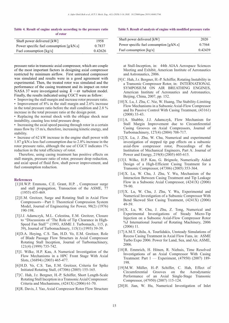
According to the input data, results were summarized in Table 4.
In the next step, amount of pressure ratio and efficiency of compressor were varied accordingly, pressure ratio was 2.11 (2.8% higher that of the 2.05) and efficiency was 1% lesser from designing point. Then the final observed result summarized below in Table 5
According to Tables 4 and 5, with the new pressure ratio and efficiency, the produced power of has increased for 62 kW. Lower fuel consumption, from 0.42626 to 0.42439 kg/s, due to pressure increase which specific fuel consumption reduced to 1.87 g/kN.s. Thus, using casing treatment could optimize engine performance and increase shaft power of engine in addition to reduction of fuel consumption.
4- ConclusionThe effect of using circumferential groove casing
treatment was investigated on the stall margin as well as total
13
Fig. 13. (a) Axial speed near tip of the blade without casing treatment (b) Axial speed near tip of the blade with casing treatment
3
Input mass flow rate [kg/s] 20.2 kg/s Compressor pressure ratio 2.05 Inlet temperature of turbine [K] 1250 K (supposed) Compressor efficiency (%) 87.7% Tip speed of the blade of compressor [m/s] 454.14 Hub to tip diameter ratio 0.7 Average Mach number inlet to the compressor 1.305 turbine efficiency 89% (supposed)
Table 3. Input data in GSTURB Software [33]
A. Jafar Gholi Beik et al.,AUT J. Mech. Eng., 4(1) (2020) 3-16, DOI: 10.22060/ajme.2019.14840.5746
15
pressure ratio in transonic axial compressor, which are couple of the most important factors in designing axial compressor restricted by minimum airflow. First untreated compressor was simulated and results were in a good agreement with experimental. Then, the treated rotor was simulated and the performance of the casing treatment and its impact on rotor NASA 37 were investigated using k ω− turbulent model. Finally, the results indicated using CGCT were as follow:• Improving the stall margin and increase rotor pressure ratio.• Improvement of 8% in the stall margin and 2.6% increase in the total pressure ratio before the stall condition and 2.8 % increase in the total pressure ratio at the design point. • Replacing the normal shock with the oblique shock near instability, causing less total pressure drop.• Increasing the axial speed passing through rotor in a certain mass flow by 15 m/s, therefore, increasing kinetic energy, and stability. • Increase of 62 kW increase in the engine shaft power with 1.87 g/kN.s less fuel consumption due to 2.8% increase in the rotor pressure ratio, although the use of CGCT indicates 1% reduction in the total efficiency of rotor.
Therefore, using casing treatment has positive effects on stall margin, pressure ratio of rotor, pressure drop reduction, and axial speed of fluid flow, shaft power improvement, and fuel consumption reduction.
References[1] H.W.P. Emmons, C.E. Grant, H.P. , Compressor surge
and stall propagation, Transaction of the ASME, 77 (1955) 455-469.
[2] E.M. Greitzer, Surge and Rotating Stall in Axial Flow Compressors—Part I: Theoretical Compression System Model, Journal of Engineering for Power, 98(2) (1976) 190-198.
[3] J.J. Adamczyk, M.L. Celestina, E.M. Greitzer, Closure to “Discussions of ‘The Role of Tip Clearance in High-Speed Fan Stall’” (1993, ASME J. Turbomach., 115, p. 39), Journal of Turbomachinery, 115(1) (1993) 39-39.
[4] D.A. Hoying, C.S. Tan, H.D. Vo, E.M. Greitzer, Role of Blade Passage Flow Structurs in Axial Compressor Rotating Stall Inception, Journal of Turbomachinery, 121(4) (1999) 735-742.
[5] I. Wilke, H.P. Kau, A Numerical Investigation of the Flow Mechanisms in a HPC Front Stage With Axial Slots, (36894) (2003) 465-477.
[6] H.D. Vo, C.S. Tan, E.M. Greitzer, Criteria for Spike Initiated Rotating Stall, (47306) (2005) 155-165.
[7] C. Hah, J.r. Bergner, H.-P. Schiffer, Short Length-Scale Rotating Stall Inception in a Transonic Axial Compressor: Criteria and Mechanisms, (4241X) (2006) 61-70.
[8] R. Davis, J. Yao, Axial Compressor Rotor Flow Structure
at Stall-Inception, in: 44th AIAA Aerospace Sciences Meeting and Exhibit, American Institute of Aeronautics and Astronautics, 2006.
[9] C. Hah, J.r. Bergner, H.-P. Schiffer, Rotating Instability in a Transonic Compressor Rotor, in: INTERNATIONAL SYMPOSIUM ON AIR BREATHING ENGINES, American Institute of Aeronautics and Astronautics, Beijing, China, 2007, pp. 152.
[10] X. Lu, J. Zhu, C. Nie, W. Huang, The Stability-Limiting Flow Mechanisms in a Subsonic Axial-Flow Compressor and Its Passive Control With Casing Treatment, (43161) (2008) 33-43.
[11] A. Shabbir, J.J. Adamczyk, Flow Mechanism for Stall Margin Improvement due to Circumferential Casing Grooves on Axial Compressors, Journal of Turbomachinery, 127(4) (2004) 708-717.
[12] X. Lu, J. Zhu, W. Chu, Numerical and experimental investigation of stepped tip gap effects on a subsonic axial-flow compressor rotor, Proceedings of the Institution of Mechanical Engineers, Part A: Journal of Power and Energy, 219(8) (2005) 605-615.
[13] I. Wilke, H.P. Kau, G. Brignole, Numerically Aided Design of a High-Efficient Casing Treatment for a Transonic Compressor, (47306) (2005) 353-364.
[14] X. Lu, W. Chu, J. Zhu, Y. Wu, Mechanism of the Interaction Between Casing Treatment and Tip Leakage Flow in a Subsonic Axial Compressor, (4241X) (2006) 79-90.
[15] X. Lu, W. Chu, J. Zhu, Y. Wu, Experimental and Numerical Investigation of a Subsonic Compressor With Bend Skewed Slot Casing Treatment, (4241X) (2006) 49-59.
[16] X. Lu, W. Chu, J. Zhu, Z. Tong, Numerical and Experimental Investigations of Steady Micro-Tip Injection on a Subsonic Axial-Flow Compressor Rotor %J International Journal of Rotating Machinery, 2006 (2006) 11.
[17] A.M.T. Ghila, A. Tourlidakis, Unsteady Simulations of Recess Casing Treatment in Axial Flow Fans, in: ASME Turbo Expo 2006: Power for Land, Sea, and Air, ASME, 2006.
[18] R. Emmrich, H. Honen, R. Niehuis, Time Resolved Investigations of an Axial Compressor With Casing Treatment: Part 1 — Experiment, (47950) (2007) 189-198.
[19] M.W. Muller, H.-P. Schiffer, C. Hah, Effect of Circumferential Grooves on the Aerodynamic Performance of an Axial Single-Stage Transonic Compressor, (47950) (2007) 115-124.
[20] H. Jian, W. Hu, Numerical Investigation of Inlet
4
Shaft power delivered [kW] 1958 Power specific fuel consumption [g/kN.s] 0.7837 Fuel consumption [kg/s] 0.42626
5
Shaft power delivered [kW] 2020 Power specific fuel consumption [g/kN.s] 0.7564 Fuel consumption [kg/s] 0.42439
Table 4. Result of engine analysis according to the pressure ratio of rotor
Table 5. Result of analysis of engine with modified pressure ratio

A. Jafar Gholi Beik et al.,AUT J. Mech. Eng., 4(1) (2020) 3-16, DOI: 10.22060/ajme.2019.14840.5746
16
Distortion on an Axial Flow Compressor Rotor with Circumferential Groove Casing Treatment, Chinese Journal of Aeronautics, 21(6) (2008) 496-505.
[21] X. Dong, X. Liu, D. Sun, X. Sun, Experimental investigation on SPS casing treatment with bias flow, Chinese Journal of Aeronautics, 27(6) (2014) 1352-1362.
[22] R. Taghavi-Zenouz, S. Abbasi, Alleviation of spike stall in axial compressors utilizing grooved casing treatment, Chinese Journal of Aeronautics, 28(3) (2015) 649-658.
[23] F. Li, J. Li, X. Dong, D. Sun, X. Sun, Influence of SPS casing treatment on axial flow compressor subjected to radial pressure distortion, Chinese Journal of Aeronautics, 30(2) (2017) 685-697.
[24] X. Xue, T. Wang, T. Zhang, B. Yang, Mechanism of stall and surge in a centrifugal compressor with a variable vaned diffuser, Chinese Journal of Aeronautics, 31(6) (2018) 1222-1231.
[25] S. Kim, K. Kim, C. Son, Three-dimensional unsteady simulation of a multistage axial compressor with labyrinth seals and its effects on overall performance and flow characteristics, Aerospace Science and Technology, 86 (2019) 683-693.
[26] A.J. Crook, E.M. Greitzer, C.S. Tan, J.J. Adamczyk, Numerical Simulation of Compressor Endwall and Casing Treatment Flow Phenomena, Journal of Turbomachinery, 115(3) (1993) 501-512.
[27] L. Reid, R.D. Moore, Design and overall performance of four highly loaded, high speed inlet stages for an advanced high-pressure-ratio core compressor, (1978).
[28] A. Boretti, Experimental and computational analysis of a transonic compressor rotor, in: Proc. Of 17th Australasian Fluid Mechanics Conference, 2010, pp. 473-476.
[29] Ansys, ANSYS Workbench Inc, in, 2017.[30] CATIA, in, 1992-2008.[31] E.-S. F, Aircraft Propulsion And Gas Turbine Engines,
CRC Press INC (2008).[32] O.H.V. Mattingly J. D., Elements of Propulsion: Gas
Turbines and Rockets, second ed, AIAA Education Serie, (2006).
[33] GasTurb, Fletcher Gas Turbine Performance, in, Blackwell Science Ltd, 1998.