amateur radio repeater fundamentals - … ran on 6 vdc, ... for new equipment, and hams would buy up...
TRANSCRIPT

Fundamentals of Amateur Radio Repeaters
Presented By: Steve Decho, KE6FX
DHRA Meeting, April 24, 2014
• History
• Propagation & Antenna Basics
• Repeater System Design & Components
Agenda

History
• Origins in the Land Mobile service on the 1950’s
• Land Mobile ~ 2-way, dispatch (e.g taxi, delivery), public safety (police, fire)
• Line-of-sight radio bands – VHF and UHF
• Frequency Modulation the mode of choice
• Early Ham radios were obsolete land mobile radios retuned to ham bands
• Motorola, General Electric, RCA
History
Propagation & Antenna Basics

Propagation – Line of Sight
Height in Feet Distance in Miles5 2.750 8.7
200 17.3
2000 54.8
6000 94.9
Line of Sight VHF/UHF Distances
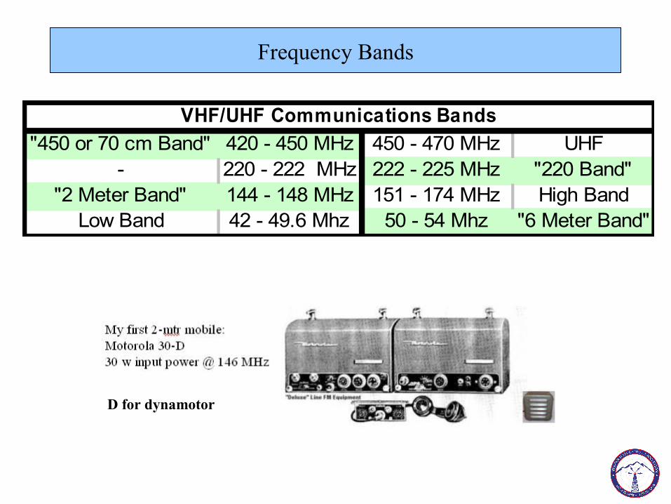
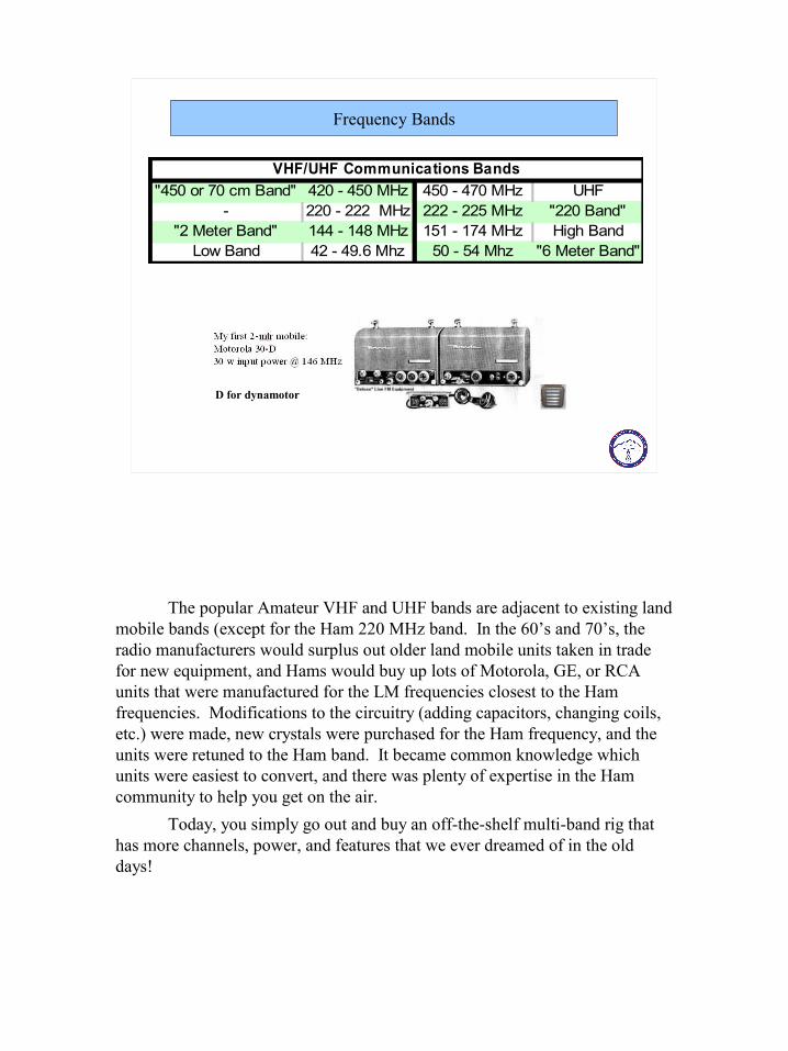
Frequency Bands
"450 or 70 cm Band" 420 - 450 MHz 450 - 470 MHz UHF- 220 - 222 MHz 222 - 225 MHz "220 Band"
"2 Meter Band" 144 - 148 MHz 151 - 174 MHz High BandLow Band 42 - 49.6 Mhz 50 - 54 Mhz "6 Meter Band"
VHF/UHF Communications Bands
D for dynamotor
Band Considerations - RF Path Loss
UHF/450 Band 6.3 in
220 Band 12.6 in
High Band / 2 mtrs 19 in
Low Band / 6 mtrs 56 in
Band Considerations - Antenna lengths (1/4 –wave ground plane)
1/4 Wave Whip Antenna
447 MHz 52 MHz
1/4 Wave Antenna Pattern – Isotropic Radiator – No Gain
Feed Line
Feed Line
½ Wave Dipole Representation
¼ Wave Whip Representation
Horizon
Vertical Polarization
Horizon
Antenna Pattern – with Gain
Feed Line
Phased Dipoles
5/8 Wave
Horizontal Plane
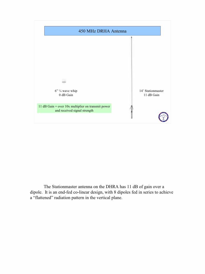
450 MHz DRHA Antenna
6” ¼ wave whip0 dB Gain
14’ Stationmaster11 dB Gain
11 dB Gain = over 10x multiplier on transmit powerand received signal strength
Repeater System Design & Components
Remote Base Station – Wire-line Controlled
Rx Tx
Receive Audio
Transmit Audio
PTT
Mobile Units
Dispatch Console
“Simplex”
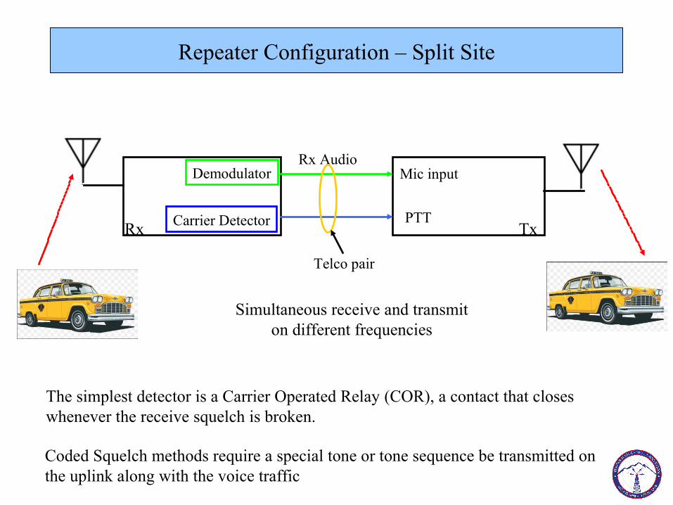
Repeater Configuration – Split Site
Rx Tx
Rx AudioMic input
PTT
Demodulator
Carrier Detector
Telco pair
The simplest detector is a Carrier Operated Relay (COR), a contact that closeswhenever the receive squelch is broken.
Coded Squelch methods require a special tone or tone sequence be transmitted on the uplink along with the voice traffic
Simultaneous receive and transmiton different frequencies
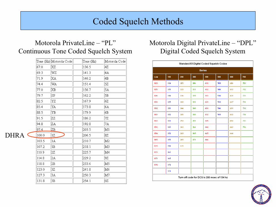
Coded Squelch Methods
Motorola PrivateLine – “PL”Continuous Tone Coded Squelch System
Motorola Digital PrivateLine – “DPL”Digital Coded Squelch System
DHRA
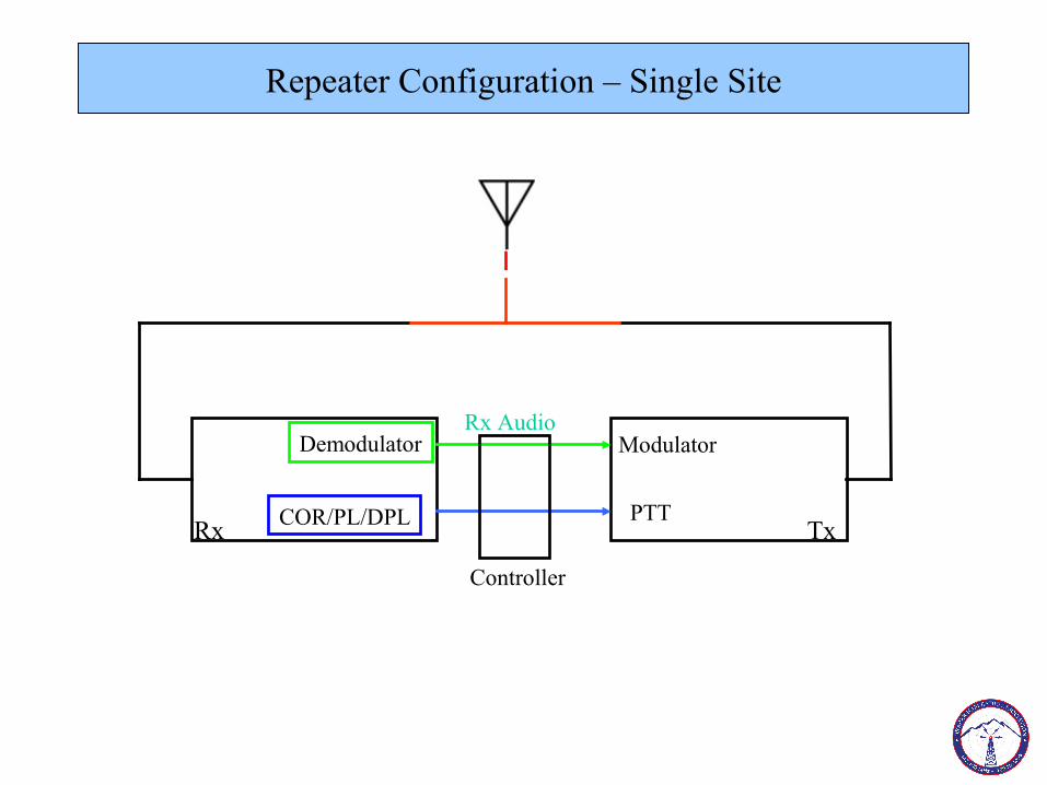
Repeater Configuration – Single Site
Rx Tx
Rx AudioModulator
PTT
Demodulator
COR/PL/DPL
Duplexer
Controller
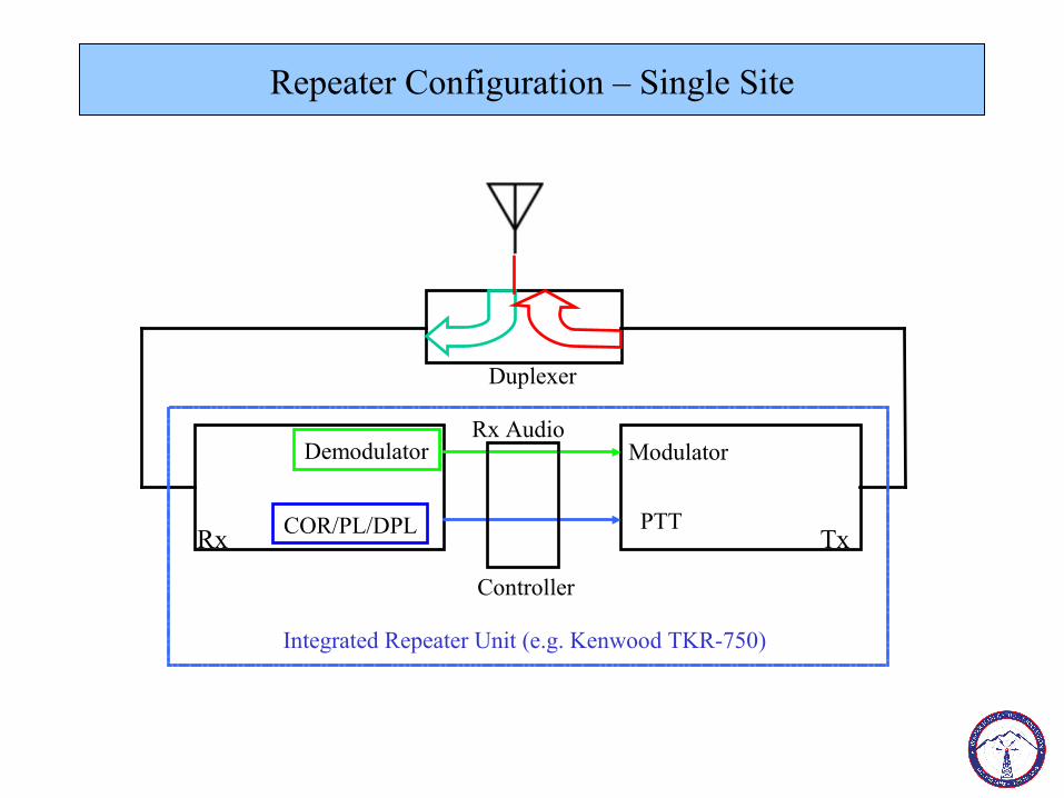
Repeater Configuration – Single Site
Rx Tx
Rx AudioModulator
PTT
Demodulator
COR/PL/DPL
Duplexer
Controller
Integrated Repeater Unit (e.g. Kenwood TKR-750)
Receive/Transmit Frequency Separation
BAND SEPARATION (Offset)
450 MHz (70 cm) -/+ 5 MHz 220 MHz (1 1/4 m) - 600 kHz
146 MHz (2 m) -/+ 600 kHz52 MHz (6 m) - 500 kHz
Duplexers for Various Bands
450 Band 2m Band 6m Band

dBm Review
A Watt is an absolute power measurement dB is a relative power measurement in logarithmic (base 10) valuesdBm is an absolute power measurement relative to 1 miliwatt
Example: P(dBm) = 10 · log10( 1000 · P(W) / 1W) or
dBm = 10 * (log (1000 * P))P = Power in Watts1000mW = 1 Watt
Absolute Relative
0 dBm = 1 milliwatt -3 dB is ½ the power10 dBm = 10 milliwatts -10 dB is 1/10 the power20 dBm = 100 milliwatts -20 dB is 1/100 the power30 dBm = 1 Watt -30 dB is 1/1000 the power40 dBm = 10 Watts -40 dB is 1/10,000 the power

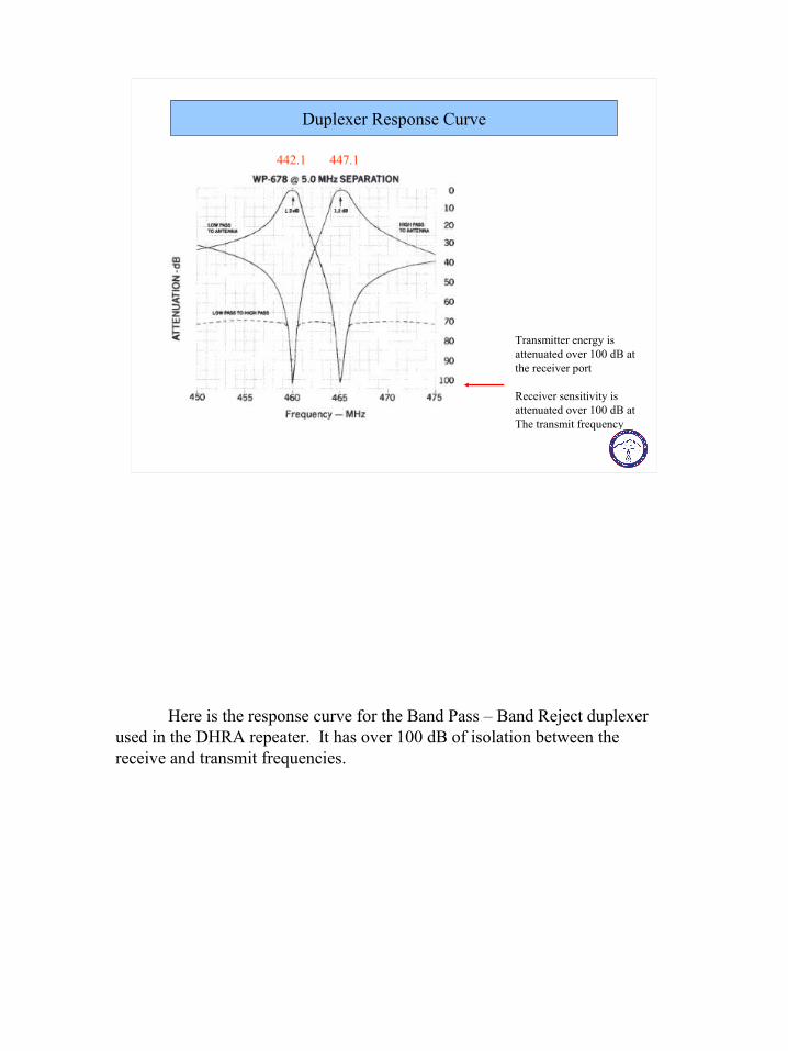
Duplexer Response Curve
Transmitter energy isattenuated over 100 dB at the receiver port
Receiver sensitivity is attenuated over 100 dB atThe transmit frequency
442.1 447.1
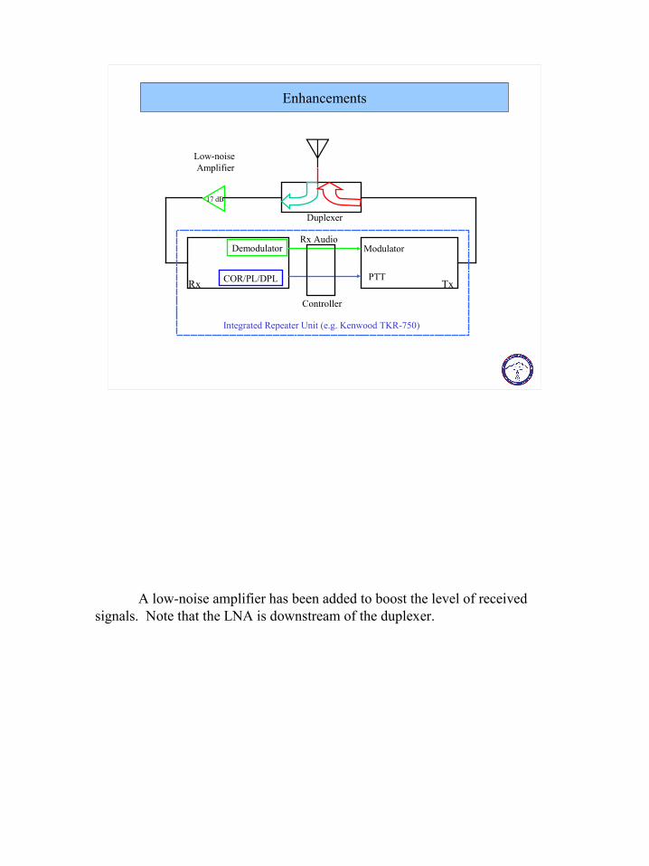
Enhancements
Rx Tx
Rx AudioModulator
PTT
Demodulator
COR/PL/DPL
Duplexer
Controller
Low-noise Amplifier
17 dB
Integrated Repeater Unit (e.g. Kenwood TKR-750)
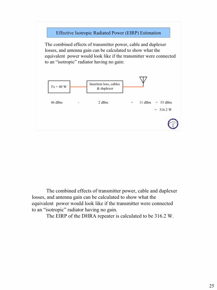
Effective Isotropic Radiated Power (EIRP) Estimation
The combined effects of transmitter power, cable and duplexer losses, and antenna gain can be calculated to show what theequivalent power would look like if the transmitter were connectedto an “isotropic” radiator having no gain:
Tx = 40 WInsertion loss, cables
& duplexer
46 dBm - 2 dBm + 11 dBm = 55 dBm
= 316.2 W
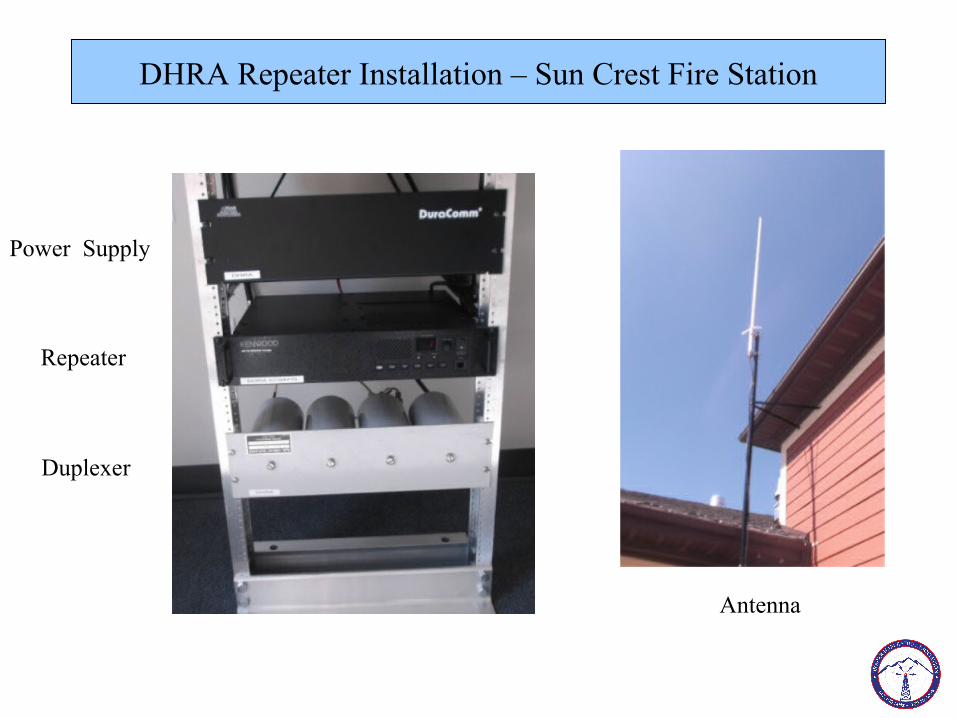
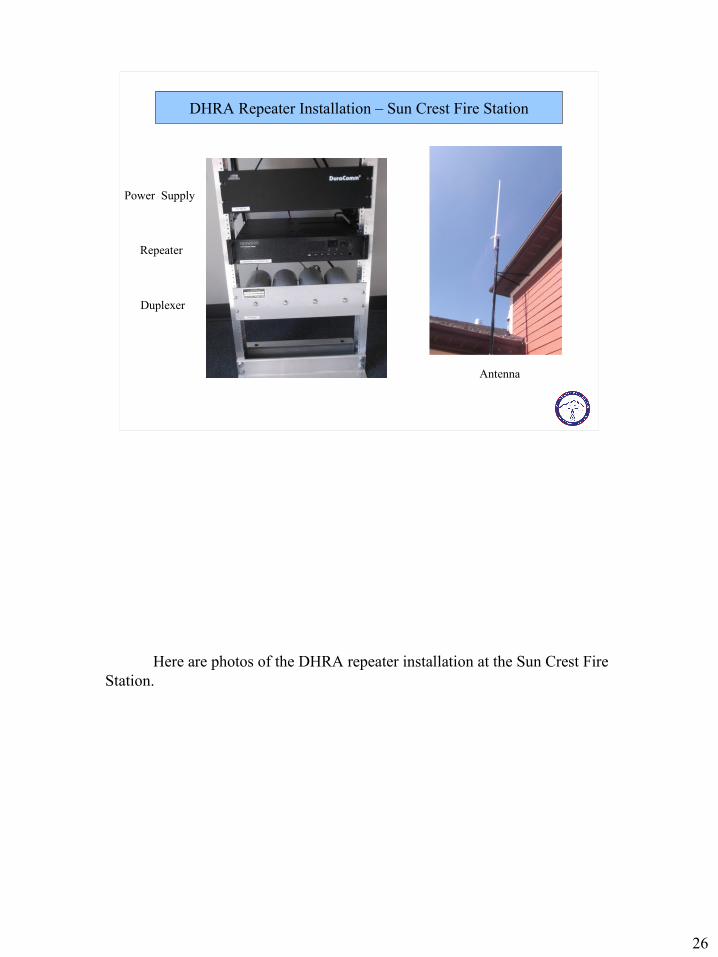
DHRA Repeater Installation – Sun Crest Fire Station
Power Supply
Repeater
Duplexer
Antenna

Fundamentals of Amateur Radio Repeaters
Presented By: Steve Decho, KE6FX
DHRA Meeting, April 24, 2014
• History
• Propagation & Antenna Basics
• Repeater System Design & Components
Agenda

History

• Origins in the Land Mobile service on the 1950’s
• Land Mobile ~ 2-way, dispatch (e.g taxi, delivery), public safety (police, fire)
• Line-of-sight radio bands – VHF and UHF
• Frequency Modulation the mode of choice
• Early Ham radios were obsolete land mobile radios retuned to ham bands
• Motorola, General Electric, RCA
History
The Ham radio VHF and UHF repeaters of today have their origins in the Land Mobile commercial radio service that predates the 1950’s. Land Mobile is a broad category that included what we consider as “two-way” radio. That would include all kinds of dispatch, such as taxis, delivery service, trucking, and many public safety services such as police, fire departments, and ambulance.
These services were set up on “line-of-sight” VHF and UHF frequencies. That is, the radio propagation does not usually extend beyond the horizon and the frequencies are too high to be reflected from the ionosphere and be heard over very long distances. This makes sense, given the localized nature of such land mobile services. The lower “HF” bands that are subject to ionospheric skip are dependent upon time of day, time of year, sunspot activity cannot be relied upon for 24/7/365 service.
Although Amplitude Modulation (AM) was tried, the industry standardized on Frequency Modulation (FM) as the mode of choice. FM offers superior immunity to noise, which is very prevalent in a mobile environment. Auto engine spark plugs, electrical power poles, street lighting, industrial motors, and weather all contribute to “static” and are inherently amplitude modulated. FM also gives a more stable volume level, since the volume does not vary with the amplitude of the received signal.
The first radios used for the VHF an UHF bands were converted land mobile units taken out of commercial service as trade-ins when newer models came out. Motorola, General Electric, and RCA dominated the market.
These radios were large, trunk-mounted units with usually only one receive and one transmit frequency. A “control head” and speaker were mounted under the dash, and a fat multi-conductor cable connected the control head to the radio. Single-ought cables connected the vehicle 12-volt battery and ground to the radio in the trunk. (The earliest mobiles ran on 6 VDC, before the automotive industry changed to 12 VDC.)
5
Propagation & Antenna Basics
Before we get into more specifics about the radios and frequency bands, let’s briefly review propagation and antennas as they relate to the VHF and UHF bands.

Propagation – Line of Sight
Height in Feet Distance in Miles5 2.750 8.7
200 17.3
2000 54.8
6000 94.9
Line of Sight VHF/UHF Distances
Here are some line-of-sight distances for various antenna heights above average terrain. Obstructions such as buildings or mountain ranges will block radio coverage in some directions. Specialized high-gain antennas can be used to extend radio coverage. My 447 mHz repeater on Mt. Disappointment (north of Pasadena, CA could hit Tijuana, Mexico, 130 miles to the south.
Frequency Bands
"450 or 70 cm Band" 420 - 450 MHz 450 - 470 MHz UHF- 220 - 222 MHz 222 - 225 MHz "220 Band"
"2 Meter Band" 144 - 148 MHz 151 - 174 MHz High BandLow Band 42 - 49.6 Mhz 50 - 54 Mhz "6 Meter Band"
VHF/UHF Communications Bands
D for dynamotor
The popular Amateur VHF and UHF bands are adjacent to existing land mobile bands (except for the Ham 220 MHz band. In the 60’s and 70’s, the radio manufacturers would surplus out older land mobile units taken in trade for new equipment, and Hams would buy up lots of Motorola, GE, or RCA units that were manufactured for the LM frequencies closest to the Ham frequencies. Modifications to the circuitry (adding capacitors, changing coils, etc.) were made, new crystals were purchased for the Ham frequency, and the units were retuned to the Ham band. It became common knowledge which units were easiest to convert, and there was plenty of expertise in the Ham community to help you get on the air.
Today, you simply go out and buy an off-the-shelf multi-band rig that has more channels, power, and features that we ever dreamed of in the old days!
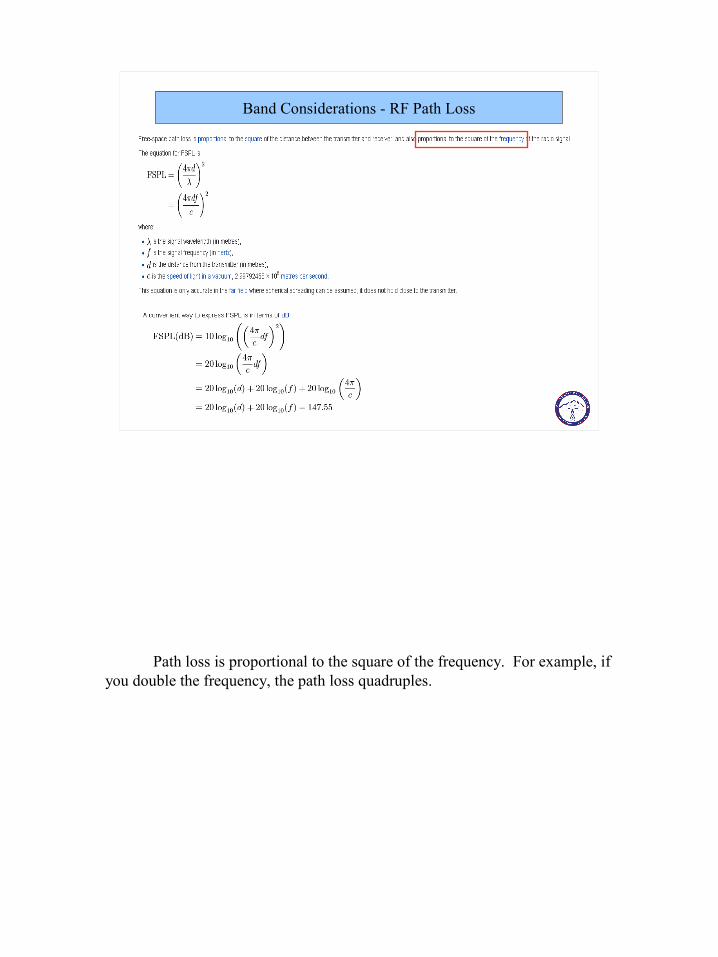
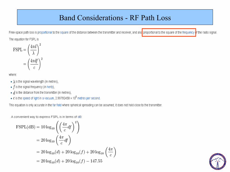
Band Considerations - RF Path Loss
Path loss is proportional to the square of the frequency. For example, if you double the frequency, the path loss quadruples.
9
UHF/450 Band 6.3 in
220 Band 12.6 in
High Band / 2 mtrs 19 in
Low Band / 6 mtrs 56 in
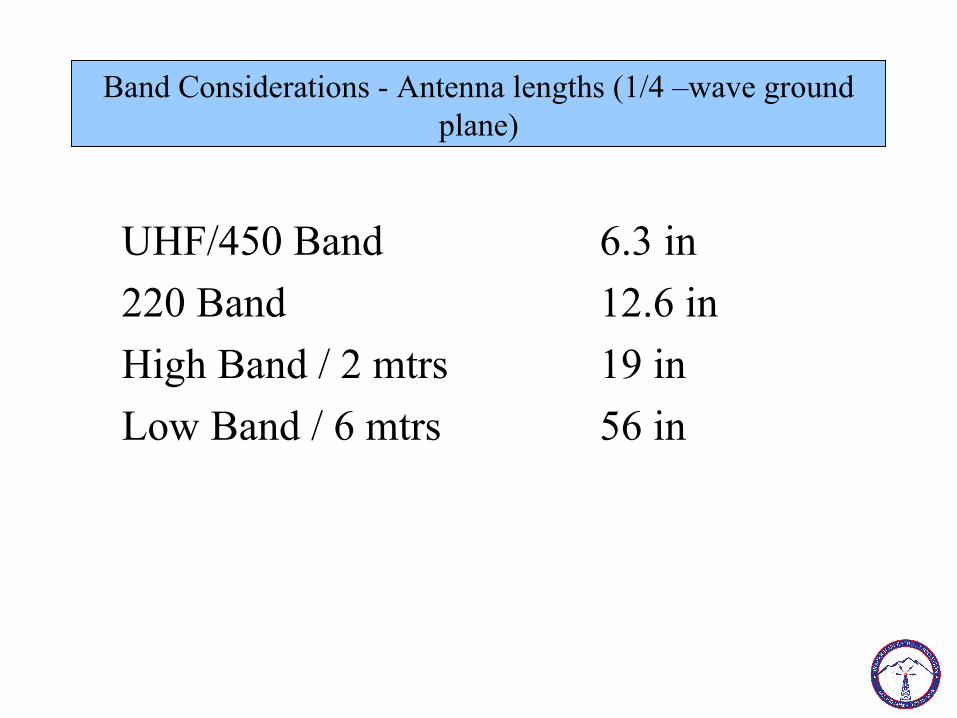
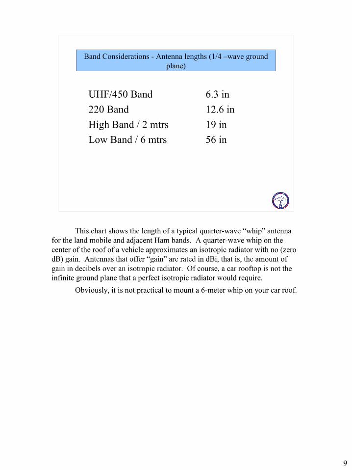
Band Considerations - Antenna lengths (1/4 –wave ground plane)
This chart shows the length of a typical quarter-wave “whip” antenna for the land mobile and adjacent Ham bands. A quarter-wave whip on the center of the roof of a vehicle approximates an isotropic radiator with no (zero dB) gain. Antennas that offer “gain” are rated in dBi, that is, the amount of gain in decibels over an isotropic radiator. Of course, a car rooftop is not the infinite ground plane that a perfect isotropic radiator would require.
Obviously, it is not practical to mount a 6-meter whip on your car roof.

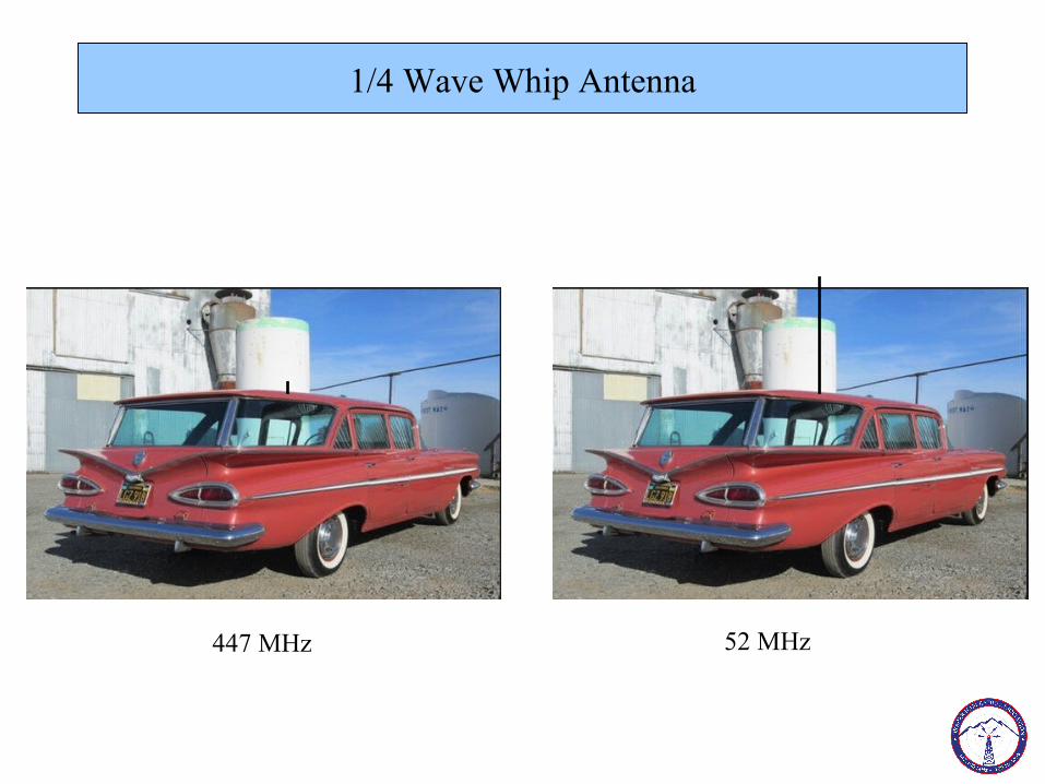
1/4 Wave Whip Antenna
447 MHz 52 MHz
A whip antenna for 447 or 2 meters is quite practical for vehicle roof mounting. Not so for 6 meters! A whip antenna assumes there is an infinite ground plane – the 59 Chevy wagon approximates that for UHF.
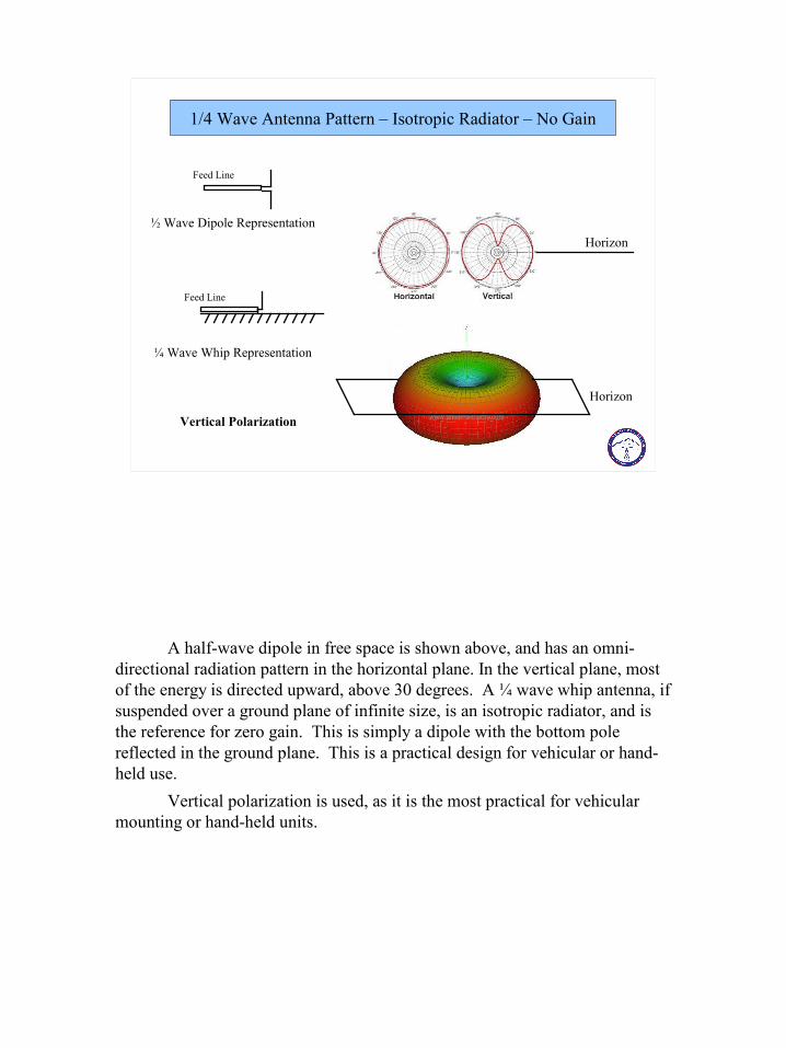
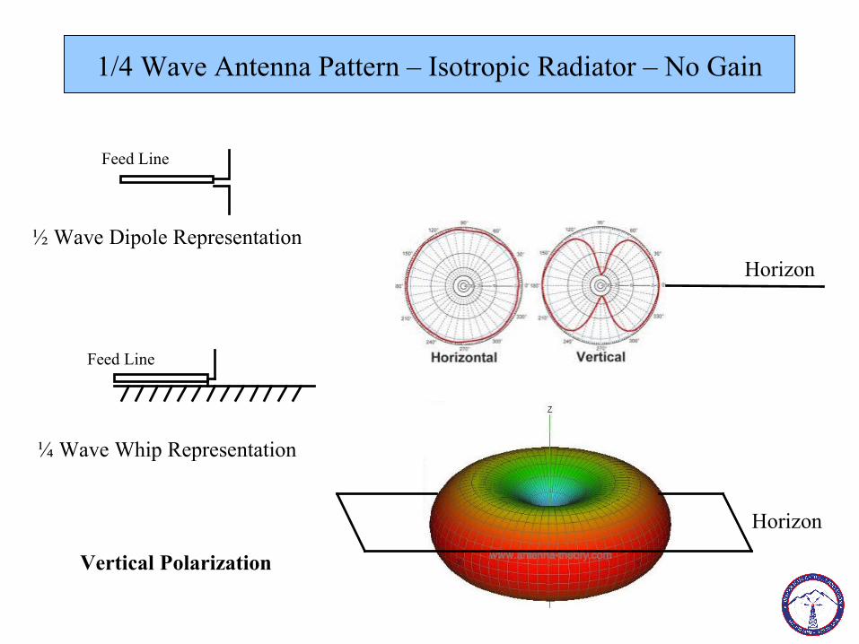
1/4 Wave Antenna Pattern – Isotropic Radiator – No Gain
Feed Line
Feed Line
½ Wave Dipole Representation
¼ Wave Whip Representation
Horizon
Vertical Polarization
Horizon
A half-wave dipole in free space is shown above, and has an omni-directional radiation pattern in the horizontal plane. In the vertical plane, most of the energy is directed upward, above 30 degrees. A ¼ wave whip antenna, if suspended over a ground plane of infinite size, is an isotropic radiator, and is the reference for zero gain. This is simply a dipole with the bottom pole reflected in the ground plane. This is a practical design for vehicular or hand-held use.
Vertical polarization is used, as it is the most practical for vehicular mounting or hand-held units.
12
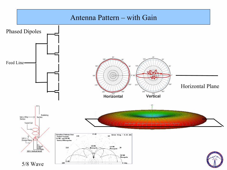
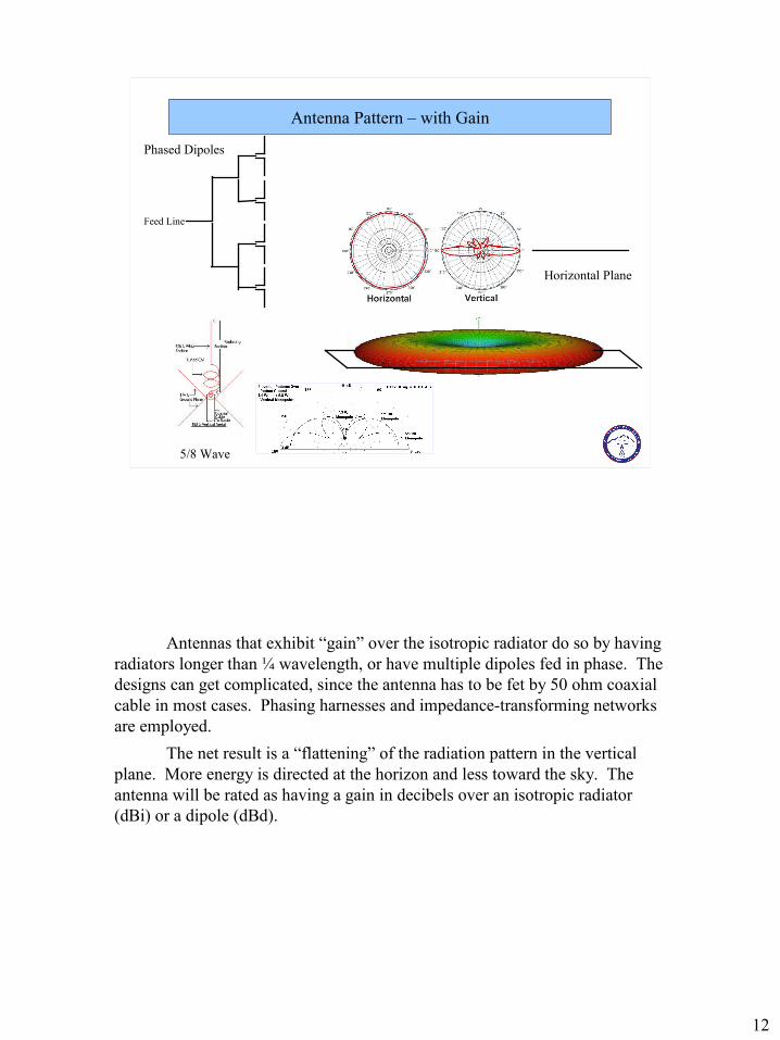
Antenna Pattern – with Gain
Feed Line
Phased Dipoles
5/8 Wave
Horizontal Plane
Antennas that exhibit “gain” over the isotropic radiator do so by having radiators longer than ¼ wavelength, or have multiple dipoles fed in phase. The designs can get complicated, since the antenna has to be fet by 50 ohm coaxial cable in most cases. Phasing harnesses and impedance-transforming networks are employed.
The net result is a “flattening” of the radiation pattern in the vertical plane. More energy is directed at the horizon and less toward the sky. The antenna will be rated as having a gain in decibels over an isotropic radiator (dBi) or a dipole (dBd).
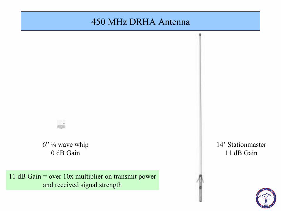
450 MHz DRHA Antenna
6” ¼ wave whip0 dB Gain
14’ Stationmaster11 dB Gain
11 dB Gain = over 10x multiplier on transmit powerand received signal strength
The Stationmaster antenna on the DHRA has 11 dB of gain over a dipole. It is an end-fed co-linear design, with 8 dipoles fed in series to achieve a “flattened” radiation pattern in the vertical plane.
Repeater System Design & Components
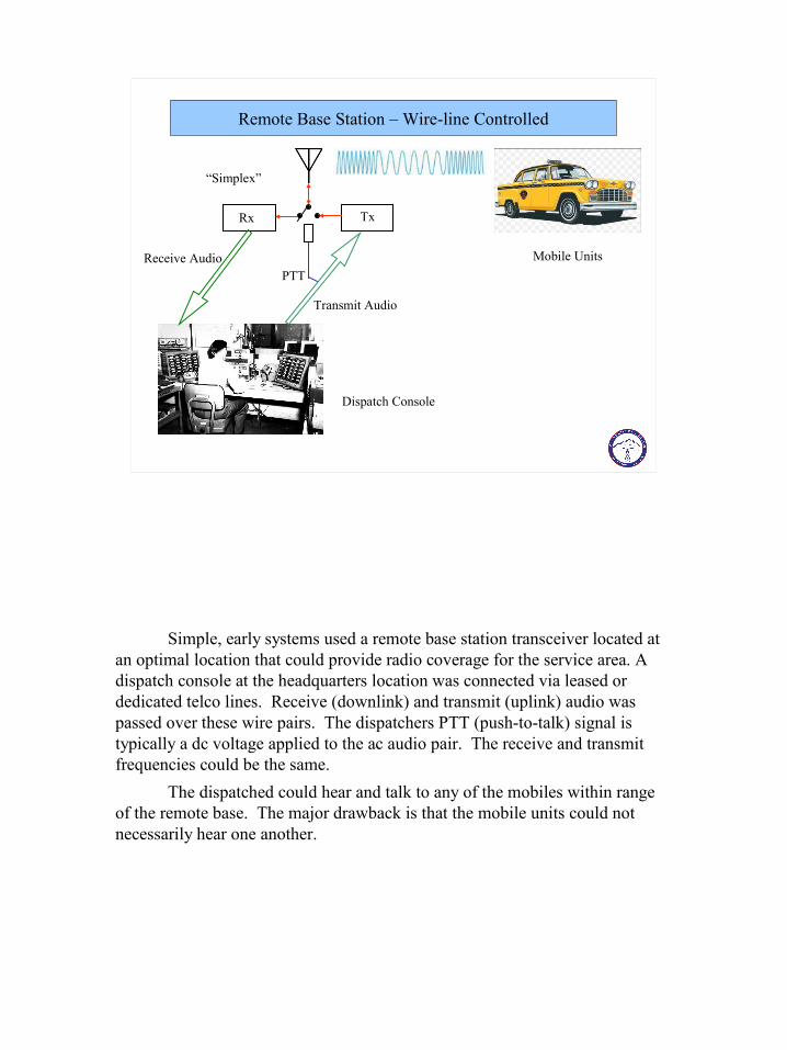
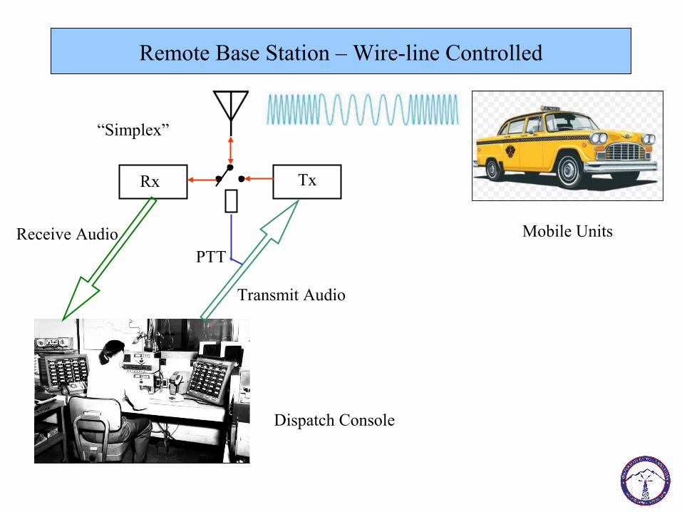
Remote Base Station – Wire-line Controlled
Rx Tx
Receive Audio
Transmit Audio
PTT
Mobile Units
Dispatch Console
“Simplex”
Simple, early systems used a remote base station transceiver located at an optimal location that could provide radio coverage for the service area. A dispatch console at the headquarters location was connected via leased or dedicated telco lines. Receive (downlink) and transmit (uplink) audio was passed over these wire pairs. The dispatchers PTT (push-to-talk) signal is typically a dc voltage applied to the ac audio pair. The receive and transmit frequencies could be the same.
The dispatched could hear and talk to any of the mobiles within range of the remote base. The major drawback is that the mobile units could not necessarily hear one another.

Repeater Configuration – Split Site
Rx Tx
Rx AudioMic input
PTT
Demodulator
Carrier Detector
Telco pair
The simplest detector is a Carrier Operated Relay (COR), a contact that closeswhenever the receive squelch is broken.
Coded Squelch methods require a special tone or tone sequence be transmitted on the uplink along with the voice traffic
Simultaneous receive and transmiton different frequencies
In order for the mobile users to hear one another, a repeater configuration is needed. The transceiver is split into separate receiver and transmitter functions, which operate independently and simultaneously. The dispatch function can now be performed from any location simply using a transceiver. The receive and transmit frequencies must now be different to allow full duplex operation without feedback or lock-up.
Here, the receiver and transmitter are in different physical locations. They are connected by wires conducting the receiver audio and a carrier detection signal that keys the transmitter when a mobile user’s uplink signal is detected. The minimum frequency difference between Rx and Tx depends on the physical antenna separation and the selectivity of the receivers involved. The mobiles operate in simplex mode, while the repeater is duplex. Split site is not very common nowadays; my first repeater was split between two different locations at the Mt. Wilson Observatory in California.
A Carrier Operated Relay (COR) is a contact that closes whenever the receiver squelch is broken. A weak or rapidly fading signal can cause the squelch to open and close rapidly, or “chatter”, so a delay timer is used to keep the PTT active for additional time after the squelch closes, thus protecting the transmitter from excessive keying.
Coded squelch methods protect against “chattering” or inadvertent keying. A sub-audible continuous tone or tone sequence must be encoded on the uplink, and detected by the repeater receiver, in order to key the transmitter. A “drop-out delay” timer is also used to reduce transmitter keying.
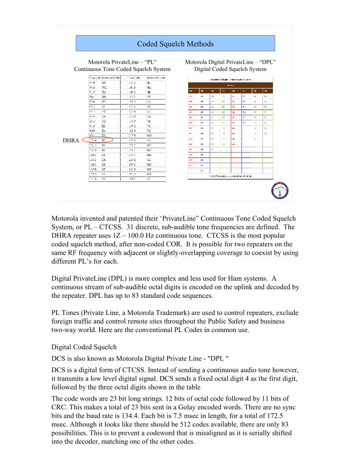
Coded Squelch Methods
Motorola PrivateLine – “PL”Continuous Tone Coded Squelch System
Motorola Digital PrivateLine – “DPL”Digital Coded Squelch System
DHRA
Motorola invented and patented their ‘PrivateLine” Continuous Tone Coded Squelch System, or PL – CTCSS. 31 discrete, sub-audible tone frequencies are defined. The DHRA repeater uses 1Z – 100.0 Hz continuous tone. CTCSS is the most popular coded squelch method, after non-coded COR. It is possible for two repeaters on the same RF frequency with adjacent or slightly-overlapping coverage to coexist by using different PL’s for each.
Digital PrivateLine (DPL) is more complex and less used for Ham systems. A continuous stream of sub-audible octal digits is encoded on the uplink and decoded by the repeater. DPL has up to 83 standard code sequences.
PL Tones (Private Line, a Motorola Trademark) are used to control repeaters, exclude foreign traffic and control remote sites throughout the Public Safety and business two-way world. Here are the conventional PL Codes in common use.
Digital Coded Squelch
DCS is also known as Motorola Digital Private Line - "DPL "
DCS is a digital form of CTCSS. Instead of sending a continuous audio tone however, it transmits a low level digital signal. DCS sends a fixed octal digit 4 as the first digit, followed by the three octal digits shown in the table
The code words are 23 bit long strings. 12 bits of octal code followed by 11 bits of CRC. This makes a total of 23 bits sent in a Golay encoded words. There are no sync bits and the baud rate is 134.4. Each bit is 7.5 msec in length, for a total of 172.5 msec. Although it looks like there should be 512 codes available, there are only 83 possibilities. This is to prevent a codeword that is misaligned as it is serially shifted into the decoder, matching one of the other codes.
Repeater Configuration – Single Site
Rx Tx
Rx AudioModulator
PTT
Demodulator
COR/PL/DPL
Duplexer
Controller
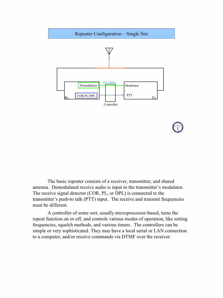
The basic repeater consists of a receiver, transmitter, and shared antenna. Demodulated receive audio is input to the transmitter’s modulator. The receive signal detector (COR, PL, or DPL) is connected to the transmitter’s push-to talk (PTT) input. The receive and transmit frequencies must be different.
A controller of some sort, usually microprocessor-based, turns the repeat function on or off, and controls various modes of operation, like setting frequencies, squelch methods, and various timers. The controllers can be simple or very sophisticated. They may have a local serial or LAN connection to a computer, and/or receive commands via DTMF over the receiver.

19
Repeater Configuration – Single Site
Rx Tx
Rx AudioModulator
PTT
Demodulator
COR/PL/DPL
Duplexer
Controller
Integrated Repeater Unit (e.g. Kenwood TKR-750)
When a common antenna is used for both receive and transmit, a duplexer must be used to isolate the receiver from the transmitter. The transmitter’s high output power will destroy the receiver’s sensitive input amplifiers otherwise, even if there is a large difference in frequency. The duplexer is a series of tunable band-pass and band-reject mechanical filters that allow the receiver and transmitter to each “see” the antenna, without seeing each other.
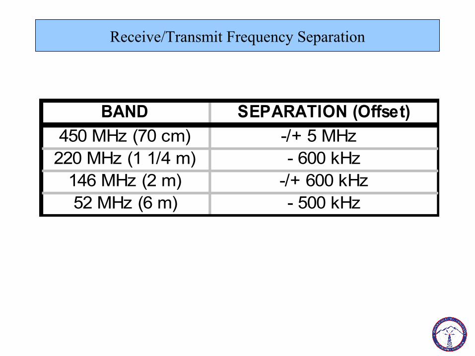
Receive/Transmit Frequency Separation
BAND SEPARATION (Offset)
450 MHz (70 cm) -/+ 5 MHz 220 MHz (1 1/4 m) - 600 kHz
146 MHz (2 m) -/+ 600 kHz52 MHz (6 m) - 500 kHz
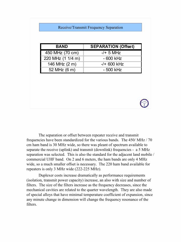
The separation or offset between repeater receive and transmit frequencies have been standardized for the various bands. The 450/ MHz / 70 cm ham band is 30 MHz wide, so there was pleant of spectrum available to separate the receive (uplink) and transmit (downlink) frequencies - a 5 MHz separation was selected. This is also the standard for the adjacent land mobile / commercial UHF band. On 2 and 6 meters, the ham bands are only 4 MHz wide, so a much smaller offset is necessary. The 220 ham band available for repeaters is only 3 MHz wide (222-225 MHz).
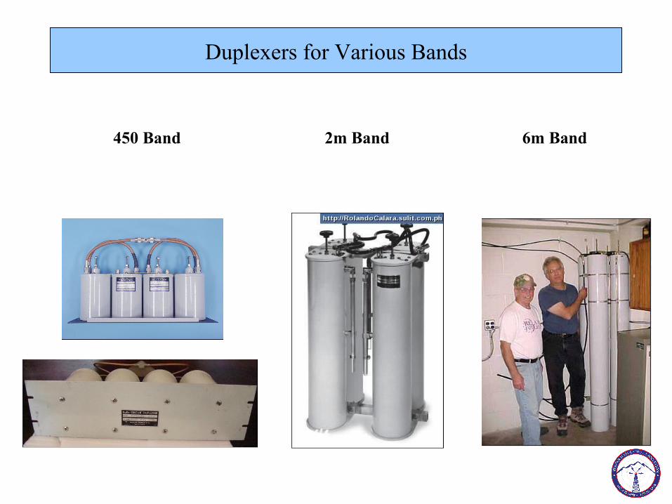
Duplexer costs increase dramatically as performance requirements (isolation, transmit power capacity) increase, an also with size and number of filters. The size of the filters increase as the frequency decreases, since the mechanical cavities are related to the quarter wavelength. They are also made of special alloys that have minimal temperature coefficient of expansion, since any minute change in dimension will change the frequency resonance of the filters.
Duplexers for Various Bands
450 Band 2m Band 6m Band
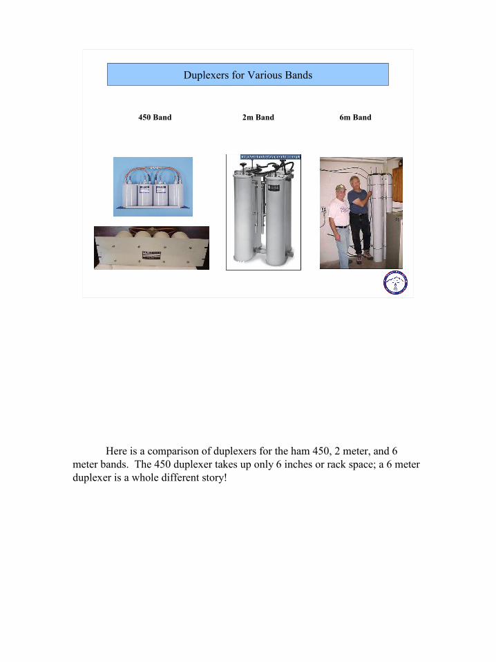
Here is a comparison of duplexers for the ham 450, 2 meter, and 6 meter bands. The 450 duplexer takes up only 6 inches or rack space; a 6 meter duplexer is a whole different story!
22
dBm Review
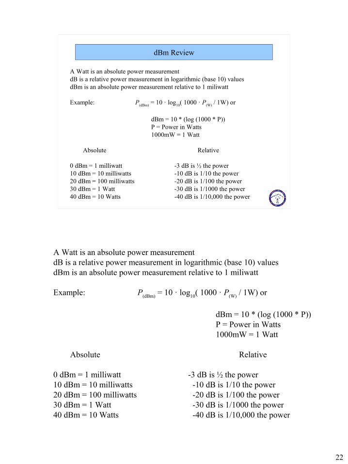
A Watt is an absolute power measurement dB is a relative power measurement in logarithmic (base 10) valuesdBm is an absolute power measurement relative to 1 miliwatt
Example: P(dBm) = 10 · log10( 1000 · P(W) / 1W) or
dBm = 10 * (log (1000 * P))P = Power in Watts1000mW = 1 Watt
Absolute Relative
0 dBm = 1 milliwatt -3 dB is ½ the power10 dBm = 10 milliwatts -10 dB is 1/10 the power20 dBm = 100 milliwatts -20 dB is 1/100 the power30 dBm = 1 Watt -30 dB is 1/1000 the power40 dBm = 10 Watts -40 dB is 1/10,000 the power
Duplexer Response Curve
Transmitter energy isattenuated over 100 dB at the receiver port
Receiver sensitivity is attenuated over 100 dB atThe transmit frequency
442.1 447.1
Here is the response curve for the Band Pass – Band Reject duplexer used in the DHRA repeater. It has over 100 dB of isolation between the receive and transmit frequencies.
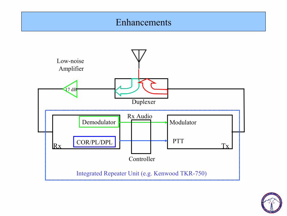
Enhancements
Rx Tx
Rx AudioModulator
PTT
Demodulator
COR/PL/DPL
Duplexer
Controller
Low-noise Amplifier
17 dB
Integrated Repeater Unit (e.g. Kenwood TKR-750)
A low-noise amplifier has been added to boost the level of received signals. Note that the LNA is downstream of the duplexer.
25
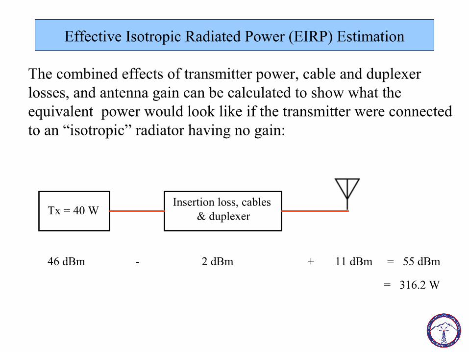
Effective Isotropic Radiated Power (EIRP) Estimation
The combined effects of transmitter power, cable and duplexer losses, and antenna gain can be calculated to show what theequivalent power would look like if the transmitter were connectedto an “isotropic” radiator having no gain:
Tx = 40 WInsertion loss, cables
& duplexer
46 dBm - 2 dBm + 11 dBm = 55 dBm
= 316.2 W
The combined effects of transmitter power, cable and duplexer losses, and antenna gain can be calculated to show what theequivalent power would look like if the transmitter were connectedto an “isotropic” radiator having no gain.
The EIRP of the DHRA repeater is calculated to be 316.2 W.
26
DHRA Repeater Installation – Sun Crest Fire Station
Power Supply
Repeater
Duplexer
Antenna
Here are photos of the DHRA repeater installation at the Sun Crest Fire Station.