ambr* engine for science missions - nasa · in-space propulsion technology (ispt) 6 design for...
TRANSCRIPT
AMBR* Engine for Science Missions
July, 2008
NASA In Space Propulsion Technology (ISPT) Program
*Advanced Material Bipropellant Rocket (AMBR)
https://ntrs.nasa.gov/search.jsp?R=20090001339 2018-06-03T20:27:32+00:00Z

2In-Space Propulsion Technology (ISPT)
Outline
Overview
Objectives
Benefits
Heritage
Results To-Date
Remaining Tasks

3In-Space Propulsion Technology (ISPT)
NRA High Temperature Bipropellant Thruster (AMBR)
Key Milestones/Upcoming EventsApproach
Objective
• Adopt operating conditions to allow the thruster to
run at higher temperatures and pressures
• Test a baseline engine for model development
• Evaluate materials and fabrication processes
• Develop advanced injector and chamber design
• Fabricate and test a prototype engine
• Environmental testing: life hotfire, vibe, and shock
tests
•Improve the bipropellant engine Isp
performance by fully exploiting the benefits
of advanced thrust chamber materials
•Goals* 335 seconds Isp with NTO/N2H4
* 1 hour operating (firing) time
* 200 lbf thrust
* 3-10 years mission life
• Kickoff Sept 2006
• Mission and System Analysis TIM Dec.
• Baseline Testing Feb. 2007
• Risk Mitigation Chamber Testing Nov.
• Prototype Engine Testing Sept. 2008
• Environmental Testing Nov.
4In-Space Propulsion Technology (ISPT)
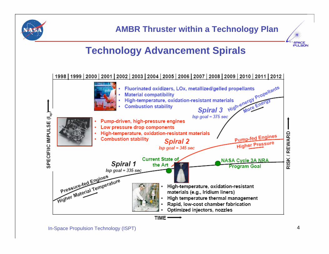
AMBR Thruster within a Technology Plan
Technology Advancement Spirals

5In-Space Propulsion Technology (ISPT)
Primary Goal
Design and test an Ir-lined Re storable bipropellant apogeeclass engine to demonstrate
• 335 seconds steady-state Isp with NTO/N2H4• 3-10 years mission life (by analysis & similarity)• 1 hour operating (firing) time• 200 lbf thrust
Secondary Goal
Investigate viability of alternate Ir/Re fabrication processes andother related material systemsDetermine whether alternate processes offer cost, producibility,and/or performance advantages over the baseline chemicalvapor deposition (CVD) Ir/Re fabrication process (El-Form hasbeen found to reduce manufacturing cost by 30% over CVD)
Goals for AMBR Thruster Development

6In-Space Propulsion Technology (ISPT)
Design for Higher Performance
Modify Aerojet’s state of the art engine design such thatthe chamber wall materials operate at their temperaturelimits while maintaining safety margins critical to missionintegrity• Optimized injector
• Optimized chamber/nozzle contour
• Reduced chamber emissivity
• Increased thermal resistance between injector and chamber
Change engine operating conditions (within missionconstraints), which will produce higher combustion gastemperatures• Higher feed pressure/lower internal pressure drop
• Higher/optimized mixture ratio
7In-Space Propulsion Technology (ISPT)
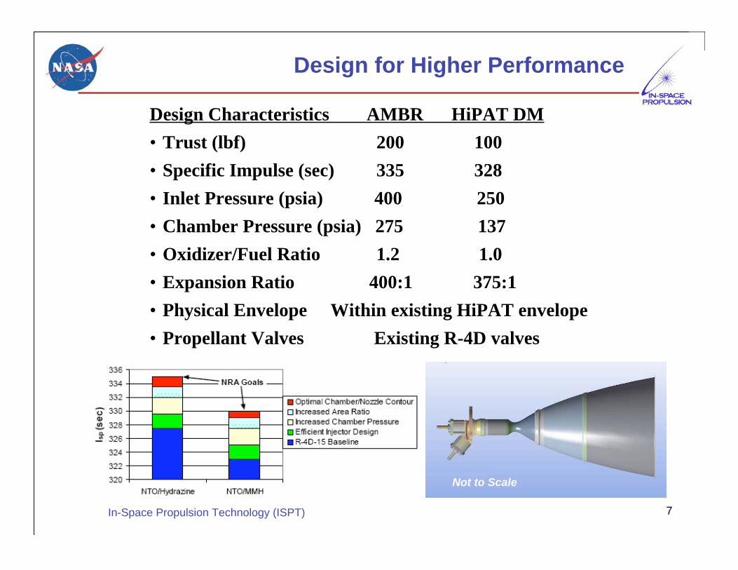
Design for Higher Performance
Design Characteristics AMBR HiPAT DM
• Trust (lbf) 200 100
• Specific Impulse (sec) 335 328
• Inlet Pressure (psia) 400 250
• Chamber Pressure (psia) 275 137
• Oxidizer/Fuel Ratio 1.2 1.0
• Expansion Ratio 400:1 375:1
• Physical Envelope Within existing HiPAT envelope
• Propellant Valves Existing R-4D valves
Not to Scale
8In-Space Propulsion Technology (ISPT)
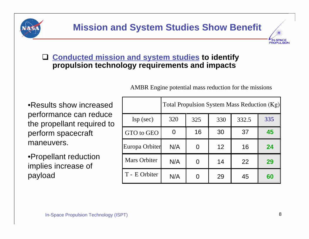
Mission and System Studies Show Benefit
Conducted mission and system studies to identifypropulsion technology requirements and impacts
•Results show increased
performance can reduce
the propellant required to
perform spacecraft
maneuvers.
•Propellant reduction
implies increase of
payload
Total Propulsion System Mass Reduction (Kg)
320 325 330 332.5 335
GTO to GEO 0 16 30 37 45
Europa Orbiter N/A 0 12 16 24
Mars Orbiter N/A 0 14 22 29
T - E Orbiter N/A 0 29 45 60
Isp (sec)
AMBR Engine potential mass reduction for the missions

9In-Space Propulsion Technology (ISPT)
Heritage
The AMBR technology is an improvementupon the existing HiPATTM engine
The HiPATTM engine is a member of theAerojet Corporation’s R-4D Family of thrusters
The R-4D family of thrusters carries theheritage: >1000 engines delivered, >650 flown,100% success rate
10In-Space Propulsion Technology (ISPT)
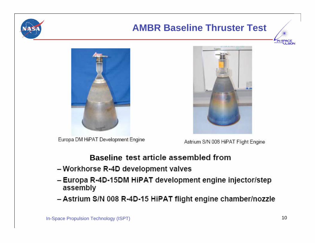
AMBR Baseline Thruster Test
Baseline

11In-Space Propulsion Technology (ISPT)
Thruster Installed and Fired
12In-Space Propulsion Technology (ISPT)
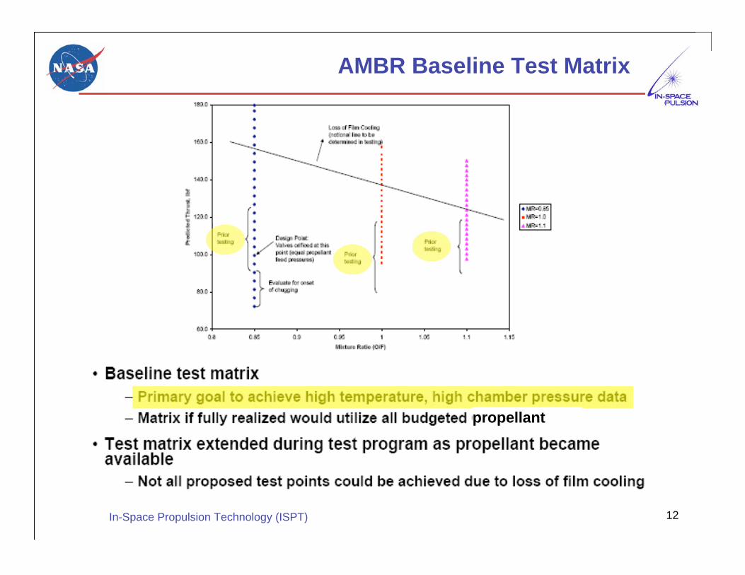
AMBR Baseline Test Matrix
propellant

13In-Space Propulsion Technology (ISPT)
Baseline Test Map

14In-Space Propulsion Technology (ISPT)
Baseline Test – Key Results Summary
4000 F--Mat’l
Capability3673 FTC
335 sec329 secIsp
275 psia217 psiaPC
New DesignTest Value
Data collected has been very important to the subsequentprototype design
15In-Space Propulsion Technology (ISPT)
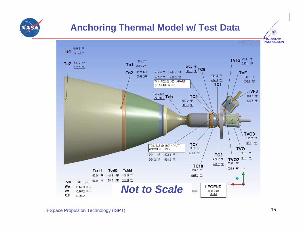
Anchoring Thermal Model w/ Test Data
Not to Scale
16In-Space Propulsion Technology (ISPT)
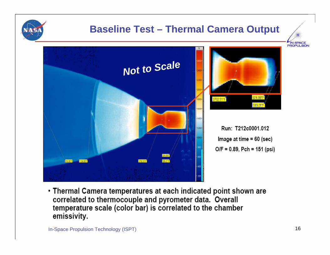
Baseline Test – Thermal Camera Output
Not to Scale

17In-Space Propulsion Technology (ISPT)
AMBR Thruster Design Detail
Defined internal chamber and nozzle contours
Finalized iridium layer thickness and an envelope thatwould contain the final rhenium thickness distribution• Using R-4D-15DM random vibration spectrum for structural
calculations
Evaluated design concepts for the injector chamberinterface and pre-combustor step assembly to accomplish• Optimization of thermal design
• Basic thermal model completed
• Anchoring thermal model to baseline engine test data
• Minimization of high cost materials
• Simplification of fabrication and construction
Performed additional injector development test with copperchamber to mitigate risk during the design phase• Injector performance and chamber length validated via C*
• Resonator design verified
• Goal of Isp 335 second is achievable

18In-Space Propulsion Technology (ISPT)
Selection of High Temperature Chamber Materials & Fabrication
Iridium coated Rhenium (Ir/Re) chamber selected
Assessed: Chemical Vapor Deposition (CVD), electroforming
(El-FormTM), Low Pressure Plasma Spray (LPPS) and Vacuum
Plasma Spray (VPS)
CVD is the incumbent process used to fabricate the R-4D-15
HiPATTM thrust chambers
El-Form has been used to fabricate an Ir/Re chamber for a
bipropellant engine
LPPS and VPS were dropped due to low technical maturity.
Figures of Merit used for the decision matrix were:Producibility
Cost – Recurring & nonrecurring
Schedule – Recurring & nonrecurring
Performance – Mechanical properties, thermal, oxidation
resistance, & mass
Heritage/Risk – Design & manufacturing
The El-Form process was down selected primarily due to the
low production cost

19In-Space Propulsion Technology (ISPT)
Chamber Materials Candidate Evaluation
Life Test Scheduled…

20In-Space Propulsion Technology (ISPT)
El-FormTM Chamber Fabrication Process
Graphite mandrel for electroforming
Ir Layer Applied to Mandrel with El-Form
Ir/Re Applied to Mandrel with El-Form
(prior to machining)
Completed EL-Form Ir/Re Nozzle
Hot-fire Test

21In-Space Propulsion Technology (ISPT)
Selection of Advanced Chamber Materials & Fabrication
CVD EL-Form
Present State ofthe art methodformanufacturingiridium/rheniumchamber
Manufacturingyield rate needsimprovement
The method usedto manufactureAMBR prototype
30% improvementon production cost(based on vendorquotations &invoice)
Iridiumrheniumchamber
Not to Scale

22In-Space Propulsion Technology (ISPT)
AMBR Thruster Chamber Undergoing Ultrasonic Testing
UT transducer
Chamber
Water TankNot to Scale

23In-Space Propulsion Technology (ISPT)
Validate core engine design characteristics usinga work horse chamber before committing to finalengine build
• Verify performance of injector design (via c*measurements)
• Verify resonator design (via accelerometermeasurements)
• Finalize chamber length (via c* measurements)
Risk Mitigation Test Objectives

24In-Space Propulsion Technology (ISPT)
Copper chamber with water cooling jacket• Used to shorten turnaround time between runs, not for active cooling
Bolt-together construction enables swapping injector
Flight-like valves and injector
Truncated nozzle eliminates expense of heat resistant materialsand fabrication plus thermal expansion mismatch with cooledchamber
Nozzle performance extrapolated from known engine data
Test Setup – Workhorse Chamber

25In-Space Propulsion Technology (ISPT)
Full scale flow pathsVariable length combustion chamber• 2.6, 3.1. 3.6 and 4.1”
Propellants• N2O4 Oxidizer and N2H4 Fuel
Injector• Flight-like titanium• Multiple unlike doublet• Fuel film cooling• Helmholtz resonators
Design nominal conditions• Chamber Pressure: 275 psia• Thrust: 170 to 210 pounds
No flow calibration restrictors• Pressure drop minimized• OF set by facility
Test Setup – Engine Configuration
26In-Space Propulsion Technology (ISPT)
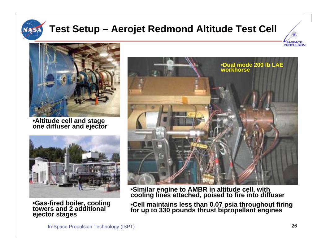
Test Setup – Aerojet Redmond Altitude Test Cell
•Altitude cell and stageone diffuser and ejector
•Gas-fired boiler, coolingtowers and 2 additionalejector stages
•Similar engine to AMBR in altitude cell, withcooling lines attached, poised to fire into diffuser
•Cell maintains less than 0.07 psia throughout firingfor up to 330 pounds thrust bipropellant engines
•Dual mode 200 lb LAEworkhorse

27In-Space Propulsion Technology (ISPT)
Test Instrumentation
Fuel Valve
OxidizerValve
Thermocouple ports
Three-axis accelerometer to
measure ignition oscillation and
damping for combustion stability
monitoringAdditional instruments/measurements:
•propellant inlet pressures
•engine chamber pressure
•propellant flow meters
Thermocouples located toanchor thermal model
28In-Space Propulsion Technology (ISPT)
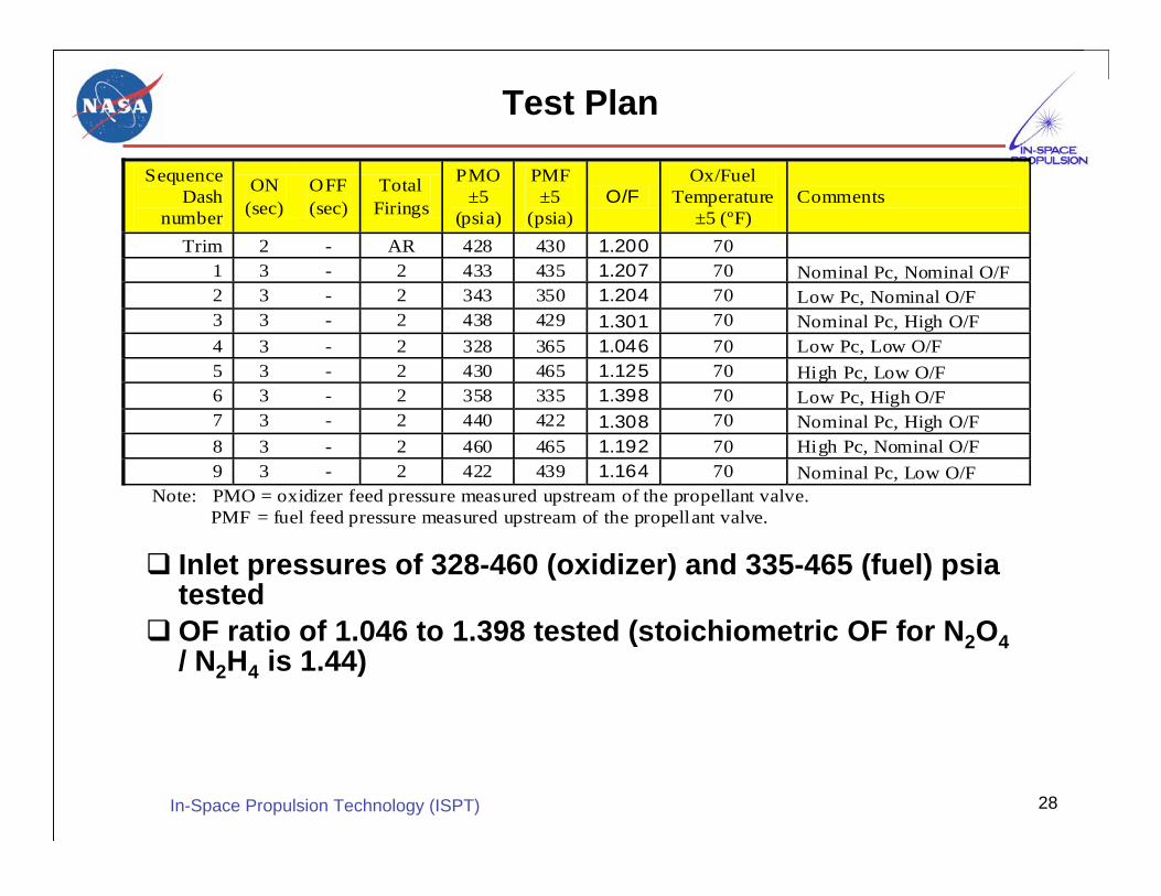
Inlet pressures of 328-460 (oxidizer) and 335-465 (fuel) psiatested
OF ratio of 1.046 to 1.398 tested (stoichiometric OF for N2O4
/ N2H4 is 1.44)
Test Plan
Sequence
Dash
number
ON
(sec)
OFF
(sec)
Total
Firings
PMO
±5
(psia)
PMF
±5
(psia)
O/F
Ox/Fuel
Temperature
±5 (ºF)
Comments
Trim 2 - AR 428 430 1.200 70
1 3 - 2 433 435 1.207 70 Nominal Pc, Nominal O/F
2 3 - 2 343 350 1.204 70 Low Pc, Nominal O/F
3 3 - 2 438 429 1.301 70 Nominal Pc, High O/F
4 3 - 2 328 365 1.046 70 Low Pc, Low O/F
5 3 - 2 430 465 1.125 70 High Pc, Low O/F
6 3 - 2 358 335 1.398 70 Low Pc, High O/F
7 3 - 2 440 422 1.308 70 Nominal Pc, High O/F
8 3 - 2 460 465 1.192 70 High Pc, Nominal O/F
9 3 - 2 422 439 1.164 70 Nominal Pc, Low O/F
Note: PMO = oxidizer feed pressure measured upstream of the propellant valve.
PMF = fuel feed pressure measured upstream of the propellant valve.

29In-Space Propulsion Technology (ISPT)
Characterize injector performance whilevarying:• Feed pressures
• Mixture ratio
• Chamber length
Demonstrate:• Fast response
• Stable ignition
• Steady-State injector operation (dynamic)
Performance goals:• 335 seconds Isp
Test Objectives

30In-Space Propulsion Technology (ISPT)
3.1 and 4.1 inch chambers tested
Maximum performance seen at OF ~1.200 in 4.1” chamber• C* = 5849 ft/s at design point
• Design inlet pressure 430 psia
• Max C* 5913 ft/sec = 1802 m/s
• Isp (est.) > 335 sec
Test Results
300
320
340
360
380
400
420
440
460
300 320 340 360 380 400 420 440 460
PMF (psia)
PM
O (
psia
)
3.1" Chamber
4.1" Chamber
5650
5700
5750
5800
5850
5900
5950
1.000 1.050 1.100 1.150 1.200 1.250 1.300 1.350 1.400 1.450
MR (O/F)
C*,
ft/
s3.1" chamber
4.1" Chamber
)(
0*
fo
tc
WW
gAPc
+=

31In-Space Propulsion Technology (ISPT)
Dynamics and Combustion Stability
Roughness approximately 3% peak-to-peak
Start response time to 90% thrust ~60 msec
Stop response time to 10% thrust ~30 msec
Accelerometer trace shows damping from start transientwithin 5 msec
Test Results (Continued)
-0.1 0
-0.0 8
-0.0 6
-0.0 4
-0.0 2
0.0 0
0.0 2
0.0 4
0.0 6
0.0 8
0.1 0
0.0 42 0 .04 3 0 .04 4 0.0 45 0.046 0.0 47 0.048 0 .04 9 0.0 5
Time [s e c ]
Ac
ce
lero
me
ter
Vo
lta
ge
[V
DC
]
Ch11 v
Ch12 v
Ch13 v
0
50
100
150
200
250
300
350
400
2 3 4 5 6 7 8 9 10
Time (sec)
Pre
ss
ure
(p
sia
)
Cha mber Pressure

32In-Space Propulsion Technology (ISPT)
Highlights of 2007 & Early 2008
Successful Baseline test laid foundation forAMBR engine design
Thermal data,
Chug information,
and pressure, MR, and thrust informationbeyond baseline engine operating envelopecollected for anchoring models
Engine performance target has been verifiedin the risk mitigation test
Prototype engine fabrication near completion
Preparation in progress to infuse AMBR thrusterinto planetary missions

33In-Space Propulsion Technology (ISPT)
Remaining Tasks
Complete AMBR fabrication (3rd Quarter 2008)
• Injector assembly, combustion chamber, nozzle,and nozzle extension
AMBR performance envelope testing (4th Quarter2008)
Environmental Testing (2008/2009)
• Vibration (Aerojet)
• Shock (JPL)
• Hotfire life test (Aerojet)