an intelligent web collaboration system for virtual
TRANSCRIPT

VEI- AN INTELLIGENT WEB COLLABORATIONSYSTEM FOR VIRTUAL ENGINEERING
by
Fuxin Sun
M.E., Pattern Recognition and Intelligent System (1999)
Tsinghua University
Submitted to the Department of Civil and Environment Engineeringin Partial fulfillment of the requirements for the Degree of
Master of Science
at the
Massachusetts Institute of Technology
June 2001
© 2001 Massachusetts Institute of TechnologyAll rights reserved
Signature of A uthor .................................... 1Department of Civil and Environment Engineering
May, 2001
Certified by ...............
Accepted by..............
.................'evin Amaratunga
Assistant Professor of Civil and E9,vironment EngineeringThesis Supervisor
...........Oral Buyukozturk
Chairman, Departmental Committee on Graduate Studies
MASSACHUSETTS INSTITUTEOF TECHNOLOGY
JUN 0 4 2001
LIBRARIES
BARKER


VEI- AN INTELLIGENT WEB COLLABORATIONSYSTEM FOR VIRTUAL ENGINEERING
by
Fuxin Sun
Submitted to the Department of Civil and Environment Engineering
On June, 2001 in Partial fulfillment of the requirements for the Degree of
Master of Science
ABSTRACT
With the globalization of world economics, more and more globally located teams are involved inthe procedure of engineering design. The teams have members working on the same project butliving around the world in different time zones and thus having different working hours. Thecollaborations among the team members are intensive and important to the success of the project.Traditional collaboration methods, such as mail, telephone and so on, cannot fulfill therequirements of fast and efficient collaborations among the team. Virtual Engineering Initiative isan intelligent web collaboration system, which is designed to meet the collaboration needs ofsuch teams. This thesis discusses the design and implementation of Virtual EngineeringInitiative.
Virtual Engineering Initiative has ten main components, which can be further classified into fourfunctional groups: video conferencing, information publishing, instant messaging, and meetingscheduling.
Video conferencing enable users to collaborate in a virtual conference room. Database backedweb publishing enables users to publish information published before, in and after. Web BasedDiscussion Boards, Email, News Group, BBS and Public Folder enable users share theirinformation when offline. Instant Messaging allows users to send messages to others in real time.By integrating commercialized systems from different vendors, Virtual Engineering Initiativeachieves high efficiency and stability.
Virtual Engineering Initiative provides Meeting Scheduler to save team members from the burdenof time-consuming meeting scheduling. Virtual Engineering Initiative chooses the distributedsystem as its meeting scheduling system structure and implements it as a software agent system.Meeting Scheduler adds an intelligent feature into the system by automating the procedure ofmeeting scheduling.
Virtual Engineering Initiative has been successfully used by the 42V Consortium as theircollaboration platform in the design procedure of a new electronic architecture.
Thesis Supervisor: Kevin AmaratungaTitle: Assistant Professor of Civil and Environment Engineering


ACKNOWLEDGEMENTS
I wish to express my sincere thanks to my advisor and thesis supervisor Professor Kevin
Amaratunga. He led me into the research of Virtual Engineering Initiative and gave me many
suggestions and supports, which are invaluable in my research.
I want to thank my officemates Julio Castrillon, JingSong Wu and Jayaprakash Pasala for
their kind help.
Fuxin Sun


TABLE OF CONTENTS
C hapter 1. Introduction ........................................................................................... 11
1.1 Elements of Collaboration.................................................................... 11
1.2 The traditional collaboration approach ............................................... 11
1.3 Web Collaboration ............................................................................... 11
1.4 Problem Statement of Virtual Engineering Initiative.............. 12
1.5 Objectives of Virtual Engineering Initiative ........................................ 13
1.6 Methodology of Virtual Engineering Initiative.................................... 13
1.7 Sum m ary ................................................................................................... 14
Chapter 2. Background.........................................................................................15
2.1 The 42V C onsortium ..................................................................................... 15
2.2 A Scenario: The Process of A Traditional Conference in The 42V
C onsortium ...................................................................................................... 15
2.3 What Does VEI Address In The Scenario?........................ . . . . . . . . . . . .. . . . . . . . . . . 16
2.3.1 Video Conferencing ............................................................................ 16
2.3.2 Information Publishing Before, During And After The Conference ... 17
2.3.3 Meeting Scheduling.............................................................................17
2.3.4 A Conference from the view of VEI...................................................... 17
2.4 Sum m ary ................................................................................................... 18
Chapter 3. The Architecture of Virtual Engineering Initiative ............................ 19
3.1 V ideo C onferencing ................................................................................... 19
3.1.1 Video Compression Standards .......................................................... 20
3.1.2 Real Time Protocol and Real Time Streaming Protocol....................21
3.1.3 Multicast vs. Unicast Video Conferencing ........................................ 22
3.1.4 The H.323 Standard - Video Conferencing Standard From ITU ..... 24
3.2 T. 120 - Standard for Data Sharing and Application Sharing ............... 25
3.3 W eb Publishing ........................................................................................ 26
3.3.1 Multimedia Database...........................................................................27
3.3.2 Data Warehousing ............................................................................... 27
7

3.3.3 Database Backed Web publishing...................................................... 27
3.4 Web Based Discussion Boards............................................................. 27
3.5 Other Information Publishing Methods.................................................. 27
3.6 Instant M essaging...................................................................................... 28
3.6.1 Instant Messaging vs. Personal Email............................................... 28
3.6.2 User Control in Instant Messaging.................................................... 29
3.7 Sum m ary ................................................................................................... 29
Chapter 4. The Approach of Virtual Engineering Initiative................................ 31
4.1 Microsoft Exchange 2000 Video Conferencing Server and NetMeeting for
Multicast Video Conferencing ........................................................................ 32
4.1.1 H.323 Video Conferencing Support in TAPI 3.0 by NetMeeting 3.01..32
4.1.2 IP Multicast Conferencing support in TAPI 3.0 ................................. 33
4.1.3 T.120 Data Conferencing Support in TAPI 3.0 by NetMeeting 3.01 .... 35
4.1.4 User Management in Video Conferencing......................................... 35
4.1.5 Real time data and application sharing ............................................... 36
4.1.6 Implementation of Multicast Video Conferencing in VEI..................36
4.1.7 A Typical Session of Multicast Video Conferencing in VEI..............37
4.2 Instant M essaging in V EI........................................................................... 40
4.2.1 Implementation of Instant Messaging ............................................... 40
4.2.2 A Typical Session of Instant Messaging in VEI ................................. 41
4.3 Offline Information Publishing in VEI ...................................................... 44
4.3.1 Web Publishing and Threaded Discussion.........................................44
4.3.2 Public Folder Sharing in VEI............................................................. 44
4.4 E m ail in V E I............................................................................................. 44
4 .5 Sum m ary ................................................................................................... . 45
Chapter 5. Distributed Meeting Scheduling System........................................... 47
5.1 Problem Statement of Meeting Scheduling...................................................47
5.1.1 What Is Meeting Scheduling in VEI? ................................................. 47
5.1.2 A Typical Meeting Scheduling Procedure ........................................ 47
5.1.3 Calendar M anagem ent......................................................................... 48
5.1.4 Communication Between Users ........................................................ 48
8

5.2 Centralized System and Distributed System................................................. 49
5.3 Sum m ary ................................................................................................... 51
Chapter 6. Meeting Scheduler -- Software Agent Approach of Meeting Scheduling
in V E I ...................................................................................................................... 5 3
6.1 User Case Diagram of Meeting Scheduler.................................................... 53
6.2 The Elements of Meeting Schedule Optimization .................................... 53
6.3 Representation of Time Preference (P)...................................................... 54
6.4 Conflict Handling...................................................................................... 56
6.5 Propagation Of Change Of The Meeting Schedule.................................... 56
6.6 Implementation of Meeting Scheduler in VEI........................................... 56
6.7 Sequence Diagram for Meeting Scheduler in VEI.................. 58
6.8 C onclusion .................................................................................................. 59
Chapter 7. Conclusion........................................................................................ 61
R EFER EN C E ...................................................................................................... 63
9

10

Chapter 1. Introduction
1.1 Elements of Collaboration
As defined in Webster's 7th Dictionary, collaboration is "to work jointly with othersespecially in an intellectual endeavor". Collaboration involves the exchange of informationand cooperation among the team. As for the view of the team member, he needs to presentthe whole team with the status of his own work, discussed his opinion about the task withothers, and adjust according to the action of the others. As for the team's view, in order to
do the above, the team needs to hold meetings for presenting the working status,discussing and adjusting work assignments. Some information could be exchanged offline,such as the proposal for the work assignment, the presentation material of current workstatus, the conclusion of the discussion, , etc. Some information has to be exchanged inreal time, such as the presentation and discussion on team meeting.
Summarizing the above, elements of collaboration can include:
* presenting working status by reports and other document formats.
* discussion in meetings0 decisions of the meetings in the format of meeting logs.
* management of member information" scheduling of meetings* message notes
1.2 The traditional collaboration approach
Before the introduction of the Internet, traditional collaboration involved regular meetingswhich every team member attended physically, team discussion over telephone, documentsexchange by mail, etc. To present working status, team members had to print out their
slides, travel to the meeting room (sometimes far way from where they are working), andshow the slides using projectors.
There are several limitations of traditional collaborations, including the high travelingexpense for team meetings, the inconvenience of talking via telephone without seeing eachother and the time consuming procedure of mail delivery. Furthermore, the collaborationdocumentations are stored in paper format, which is not easy to manage and search in later
use.
1.3 Web Collaboration
Web collaboration is a method that enables teams to exchange information and work
jointly over the Internet. Unlike normal web applications, such as web browsing, file
11

transferring, and video broadcasting, web collaboration emphasizes the sharing andexchange of information within the team, and most importantly, interaction among teammembers. Web collaboration is a result of the great improvement of the Internet.
The Internet has been improved to a new stage in recent years. The increase of networkbandwidth and convenient access make the transfer of information transferring faster andcheaper than before, compared with low bandwidth telephone networks, expensive privatenetworks and the inconvenience of mailing paper documents from one office to another.The faster and cheaper Internet connection makes real-time or near real-time informationexchange applicable, which is the most important requirement of web collaboration. Theway of communication within a team, especially communication over long distance, ischanging to web collaboration.
Web collaboration not only includes offline information exchange, such as email, filetransferring and web browsing, but also real-time information exchange, such as videoconferencing and application sharing. The web collaboration supports not only informationexchange between peers, i.e. personal email, but also information exchange among severalteam members such as multi-point data conferencing and multicast video conferencing.
The comparison in Table 1.1 shows that the web collaboration has advantages in speed,cost, security and document management over the traditional collaboration:
Table 1.1A Comparison of Web Collaboration and Traditional CollaborationWeb Collaboration Traditional Collaboration
Speed Documents are transferred in Documents are mailed in paperdigital format, i.e. email and format, usually takes hours toinstant message, which can be deliver.received within second.
Cost Online meeting enables team Regular meeting requires attendeesmembers attend the same meeting to attend the meeting physically. Itwhile they are at different takes team members days inlocations. traveling, which is expensive and
exhausting.Security Digital documents can be Documents are usually mailed in
encrypted before transferring and plain format.decrypted after receiving.
Document The documents used in Paper documents are not easy toManagement collaboration can be stored in index and search.
database, which is easy to manage.
1.4 Problem Statement of Virtual Engineering Initiative
Virtual Engineering Initiative is a web collaboration system designed to automate andassist collaboration among team members during the engineering procedure. The teamcould be globally located, which means the team members may work in different physicallocations. Collaborations within such a team are very intensive. Team members need tohold meetings to present the current working status, problems encountered, anddiscussions on possible solutions. Some team members might also exchange their opinions
12

peer-to-peer outside the meetings. For reference usage, the team also needs to manageseveral kinds of documents, such as proposals and reports, meeting discussions anddecisions, and so on. Every team member can access those documents easily.
But the fact that the team members work in different locations poses many problems forthe collaboration within the team. The team members cannot waste two days per weektraveling to attend a weekly team meeting, which is the primary format of collaborationwithin the whole team. The information exchange between two members cannot totallyrely on mail and telephone, since they are not fast and convenient enough. Documentmanagement within that team might also be a big problem. How can a team memberaccess the document he wants no matter when it is and where he is? How to maintain theconsistency of documents in the hand of different members?
Summarizing the above, there are three main problems that need to be addressed in theVirtual Engineering Initiative:
" meetings within a globally located team without the need of traveling.* real-time information exchange among team members.* document management to allow team members to access the document
conveniently.
1.5 Objectives of Virtual Engineering Initiative
By utilizing the technologies of collaboration on the Internet, the Virtual Engineering
Initiative can fulfill all the requirements of collaboration within a team listed in the abovesection. The Virtual Engineering Initiative is designed to meet the following requirements:
" video conferencing for a globally located consortium" real-time sharing* application sharing for real-time demos* information archiving and searching* instant messaging* user management to provide universal management for user identification and
access control* automating the procedure of meeting scheduling.
1.6 Methodology of Virtual Engineering Initiative
Virtual Engineering Initiative divides the whole web collaboration into seven subsystemsand integrates commercialized software systems to achieve the goal.
The subsystems are as follows:
* user management system: Microsoft Active Directory Server
" multicast video conferencing system: Microsoft Windows 2000 AdvancedServer and Professional, Microsoft Exchange 2000 Video Conferencing Serverand Microsoft NetMeeting
13

* multi-point document/data sharing systems: Lotus Domino Server integratedwith web server; Microsoft Exchange 2000 Server with Outlook as emailserver and client; Microsoft Exchange 2000 Server and NetMeeting as dataconferencing server and client
" application sharing system: Microsoft Exchange 2000 Server and NetMeetingas application sharing server and client
* information archiving system: Lotus Domino Server* instant Messaging: Microsoft Exchange 2000 Server and MSN Messager* automatic meeting scheduling: Microsoft Exchange 2000 Server and Outlook
and Software Agent Meeting Scheduler.
1.7 Summary
Virtual Engineering Initiative is an intelligent web collaboration system, which is designedto meet the collaboration needs in the procedure of engineering design. By integratingcommercialized systems from different vendors, Virtual Engineering Initiative achieveshigh efficiency and stability. Meeting Scheduler adds an intelligent feature into the systemby automating the procedure of meeting scheduling.
The thesis will give a detailed description of the background in chapter 2. In chapter 3, thearchitecture of the system will be discussed. Chapter 4 gives the system approach.Distributed Meeting Scheduling System will be discussed in Chapter 5 and Chapter 6.Chapter 7 is the conclusion of the thesis.
14

Chapter 2. Background
Virtual Engineering Initiative (VEI) is a web collaboration system designed to meet therequirements of a distributed team in engineering design. As an application in the 42VConsortium, VEI provides the consortium with the ability to collaborate in the wholeworking process.
2.1 The 42V Consortium
The 42V Consortium was founded to create a new 42-Volt architecture for cars of thefuture. The consortium includes 49 researchers and engineers from Daimler-Benz, Ford,MIT, Motorola, Siemens Automotive, Yazaki , etc. The members of the consortium areglobally located, seven members are in Europe, two members are in Japan and the othersare in eight different cities in U.S.A. There are intensive collaborations within theconsortium in the design of a new electronic architecture for cars, such as meetings,document exchanges, message calls, and so on. Traditional collaboration methods are notefficient enough for the 42V Consortium. It is too expensive not only in term of thetraveling time but also in term of the traveling expenses for all the members from differentcountries to come to the same conference room for a weekly meeting. It is also too timeconsuming to send documents from USA to Japan or Europe and wait for several daysbefore the comments come back in the same way. The consortium will also have hundredsof proposals and group discussions related to different subsystems in the 42V electricarchitecture, the paper documents in the traditional collaboration are too difficult to indexand search.
2.2 A Scenario: The Process of A Traditional Conference inThe 42V Consortium
After the consortium manager decides to hold a meeting to discuss a specific topic, hebegins to schedule the conference by choosing the date and location of the meeting andthen making a serial of calls to the potential participants. If all the participants accept thedate and location, the meeting schedule is settled; otherwise, the consortium managerneeds to choose another date or location and call the participants again. In most cases, thelocation is easy to be accepted, the date of the meeting needs to be negotiated for severaltimes.
After the date and location is settled, the manager will reserve the conference room andhotel and the participants need to book their ticket for the travel.
At the date of meeting, all the participants will come to the conference room. Approachesof current tasks will be presented by posting on the whiteBoards or projecting onto the
15
wall; printed materials will be prepared before the meeting and distributed to the audienceat the meeting.
The procedure of the meeting might be recorded and the presentations can be publishedtogether as the proceeding of the conference, which will be printed and sent to theparticipants later.
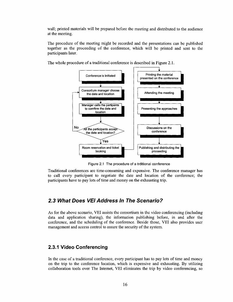
The whole procedure of a traditional conference is described in Figure 2.1.
Conference is Initiated
4,
Consortium manager choosethe date and location
4,Manager calls the partipants
to comfirm the date andlocation
iII
No I the participants accepthe date and location?
Yes
Room reservation and ticketbooking
Printing the materialpresented on the conference
Attending the meeting
Presenting the approaches
Discussions on theconference
Publishing and distributing theproceeding
Figure 2.1 The procedure of a trditional conference
Traditional conferences are time-consuming and expensive. The conference manager hasto call every participant to negotiate the date and location of the conference; theparticipants have to pay lots of time and money on the exhausting trip.
2.3 What Does VEI Address In The Scenario?
As for the above scenario, VEI assists the consortium in the video conferencing (includingdata and application sharing), the information publishing before, in and after theconference, and the scheduling of the conference. Beside those, VEI also provides usermanagement and access control to assure the security of the system.
2.3.1 Video Conferencing
In the case of a traditional conference, every participant has to pay lots of time and moneyon the trip to the conference location, which is expensive and exhausting. By utilizingcollaboration tools over The Internet, VEI eliminates the trip by video conferencing, so
16
i
that participants just need to access the Internet either in their offices or even from theirhomes. In video conferencing, every participant can send and receive video data to theothers at the same time and exchange information in a virtual conference hall.
2.3.2 Information Publishing Before, During And After TheConference
Meeting participants might want to publish information before, during and after theconference. Before the conference, a participant may publish his approach to theconference, so that every one can have some prior knowledge about what he is going topresent. During the meeting, the participant will present demos. After the conference, theproceedings including prominent presentations will be published and sent to theconference participants.
VEI supports online information publishing at any time. Conference participants canpublish their presentations and other referential materials whenever they are required.Moreover, VEI provides the management of the information published on everyconference. The Consortium on 42V project has had 27 online meetings in the period fromMar. 1999 to Jan. 2001. VEI provides browsing and searching on all the meetingdocuments. VEI also support threaded discussion related to the meeting.
2.3.3 Meeting Scheduling
To save the consortium manager from the efforts of calling each participant to find anacceptable meeting date, a software agent, Meeting Scheduler was provided for VEI. TheMeeting Scheduler can negotiate the meeting schedules automatically on behalf of its
users, the meeting participants. The Meeting Scheduler can find a near-optimized date fora specific conference.
2.3.4 A Conference from the view of VEI
Figure 2.2 illustrates the diagram of a conference from the view of VEI:
17

Conference is Initiated
Scheduling of the conferenceby Meeting Scheduler
information Publishing beforethe conference
Video Conferencing with dataand document and application
sharing
IIII
Information publishing afterthe conference
Further threaded discussions
Information archived andindexed
Figure 2.2 A conference from the view of Virtual Engineering Initiative
2.4 Summary
VEI is an intelligent collaboration system designed to meet the requirements of efficientcollaboration. As an application, VEI provides video conferencing, information publishingbefore, during and after the conference, and meeting scheduling to assist the 42VConsortium in its weekly meetings.
18
II
I

Chapter 3. The Architecture of Virtual EngineeringInitiative
Virtual Engineering Initiative has ten functional components; four of which are real timecollaboration subsystems, namely Video Conferencing, Data Sharing, Application Sharing,and Instant Messaging; four of which are offline collaboration subsystems, namelyDiscussion Boards , Email, Public Folder and Web Publishing; User Management andAccess Control, which provides user identification and access control for all the othersubsystems; and Meeting Scheduling, which automates the negotiation procedure whenscheduling video conferencing. Figure 3.1 gives the whole picture of the architecture ofVirtual Engineering Initiative.
Data Sharing(T.120)_
(T. 120)
Instant Messaging
-K
I-
- I
-H
-A
Meeting Scheduling i
User Management andAccess Control
-- - - - - - - - -
Offline Collaboration
Discussions Board
- I
KF
Email(SMTP, POP3)
Public Folder
Web Pulishing
Figure 3.1 The Architecture of Virtual Engineering Initiative
3.1 Video Conferencing
Video conferencing is one of the most important functional components in Virtual
Engineering Initiative. By means of video conferencing, users can hold virtual meetings as
if they are face to face in the same conference room.
To support video conferencing, VEI needs to have the ability to transfer streamed video
data in real-time. The data captured by a digital video camera consist of sequenced static
images, which are then compressed, encoded into stream video format and sent to the
19
Real Time Collaboration
Video Conferencing(H.323) I
I.
-I

receiver. The receiver decodes the data and displays the video after the streamed videodata are received.
The diagram of the above scheme is depicted in Figure 3.2.
Video Data Capturedby Digital Camera
Compressed andEncoded into Stream
Video Format I
Video Displayedin Real-time
Decoded andDecompresed from
Stream Video Format INetworl DeviceNetwor Device
Network Switch
Figure 3.2 The diagram of Video Conferencing
The quality of video is very much related to the compression method used during encodingand the protocol used when transferring data between the sender and the receiver. In thefollowing parts of this section, we will give a brief overview on both video compressionstandards used in video conferencing and real time data transfer protocols. We will alsodiscuss multicast and unicast video conferencing. At the end of this section, we will givean overview of the H.323 standard, the video conferencing standard chosen by VEI.
3.1.1 Video Compression Standards
Currently, the most important video compression standards used in video conferencing areH.261, H.263, MJPEG, MPEG1, MPEG2 and MPEG4[3].
H.261 is designed for face-to-face videophone applications and videoconferencing overISDN. The compression algorithm used in H.261 tends to optimise bandwidth usage bytrading picture quality against motion, e.g. a quickly-changing video will have a lowerquality than a relatively static video, so that H.261 can have the property of constant-bit-rate. H.261 supports two picture formats, which are common interchange formatCIF(352x288 ) and quarter common interchange format QCIF(176x144).
H.263 is designed to be used in a wide range of bitrates and especially targeted at betterlow-bit-rate communication, such as 28.8K modem connections[4]. H.263 improves theperformance and error recovery of H.261. H.263 supports three additional picture formats,
20
I I

which are sub-quarter common interchange format (SQCIF, 128x96), 4CIF(704x576), and
16CIF(1408x1 152). SQCIF is approximately half the resolution of QCIF. 4CIF and 16CIFare 4 and 16 times the resolution of CIF respectively.
The comparision of the five picture formats is summarised in Table 3.1[5].
Table 3.1 Comparison of the picture formats used in H.263/H.261
Picture H.261 H.263 Uncompressed bitrate (Mbit/s)
Format Support Support Grey 10Color Grey 3fpColor
SQCIF 128x96 Yes 1.0 1.5 3.0 4.4
QCIF 176x144 Yes Yes 2.0 3.0 6.1 9.1CIF 352x288 Optional Optional 8.1 12.2 24.3 36.54CIF 704x576 Optional 32.4 48.7 97.3 146.0
16CIF 1408x1152 Optional 129.8 194.6 389.3 583.9
MJPEG is an algorithm which uses JPEG to compress individual frames of a video
sequence, it can be interpreted as "Motion JPEG". But in fact, there is no commonly usedstandard for MJPEG, various vendors may have different implementations. At low bit rate,the quality of MJPEG may be poor but its latency is smaller than the other videocompression algorithms since MJPEG does not use inter-frame compression.
Like H.261, H.263 and MJPEG, MPEG-1 ad MPEG-2 are also DCT-based videocompression standards. While MPEG-i is designed to offer VHS quality video at CIF(352x288) resolution and 30 frames per second with a bandwidth of 1-1.5 Mbps, MPEG 2extends MPEG 1 to offer broadcast quality full-screen video and CD quality audio with the
bandwith of 4-15Mbps. Since they are more computational intensive and bandwidthcomsuming, then cannot be used in video conferencing over the Internet.
Unlike MPEG-i and MPEG-2, MPEG-4 is based on the segmentation of audiovisualscenes into AVOs or "audio/visual objects" which can be multiplexed for transmission
over heterogeneous networks, MPEG-4 also tends to provide a compression scheme for
low-bit-rate video conferencing.
Since VEI is targeted to globally located teams, whose members may have the Internetconnection using modems, VEI has to support low-bit-rate data transmission in video
conferencing, such as SQCIF, QCIF and CIF.
3.1.2 Real Time Protocol and Real Time Streaming Protocol
Real Time Protocol (RTP) is the Request for Comments (RFC) standard for transport of
real-time data, including audio and video, on the Internet. The services provided by RTP
include time reconstruction, loss detection, and security and content identification[ 14].
RTP consists of a data and a control part called RTCP. RTCP supports real-time
conferencing of groups of any size on The Internet. RTCP also support Multicast -to-
unicast translators for Multicast video conferencing[3].
21

Like RTP, Real Time Streaming Protocol (RTSP) is a communication protocol for controland delivery of real-time media over the The Internet. RTSP is submitted to the InternetEngineering Task Force (IETF) in October 1996 by RealNetworks and NetscapeCommunications Corporation and with support from over 40 leading media companies.RTSP defines the connection between streaming media clients and servers and provides astandard way for clients and servers from different vendors to stream media content. RTSPis built on top of The Internet Protocols, such as UDP, TCP/IP, RTP, SCP and IPMulticast.
There are three major existing commercial real time streaming video systems used in livevideo broadcasting, as listed in Table 3.2.
Table 3.2 Major Streaming 'ideo SystemsFile
Format Name Company Streaming Server Extension
RealAudio/RealVideo RealNetworks RealProducer RMstreamed content[2]Advanced Streaming Microsoft Windows Media ASFFormat Encoder
QuicktimeLive Apple QuickTimeQuicktime___ive__App__eStreaming Server QT
All of the three commercial streaming servers support multiple video compression codecs(Coding/Decoding), such as H.263, MPEG-1, and MPEG-2, but the formats of their videostreams are different so that their streams have to be played back by corresponding clients.All of the three streaming servers can directly encode video data from camera andbroadcast the stream out. But they are designed for simple broadcasting, i.e., one to manysingle direction broadcasting, so they are too heavy to support the intercommunications ofvideo conferencing, i.e., peer to peer or multiple to multiple bi-directional videocommunication. VEI cannot use any of the above video systems as its video conferencingsubsystem.
3.1.3 Multicast vs. Unicast Video Conferencing
Unicast, Broadcast and Multicast are three fundamental types of IPv4 transmissionservices. Unicast is designed to transmit a packet from one source to a single destination;Broadcast is used to send a packet from one source to an entire subnetwork; Multicast isdesigned to enable delivering data from one source to a set of hosts that have beenconfigured as members of a Multicast group in various scattered subnetworks[6]. Figure3.3 illustrates a brief comparison of the three transmission services.
22

Se er
~YF.. W on Ro ter
------ Subne rA
Router Router
Subnetwork B
Figure 3.3a Unicast. The packet is sent from one source to a single destination.
Desti tion
Dsiet ter - ' Router ----- Router
....... Subnetwork BSubnetwork A
Figure 3.3b Broadcast. The packets can only be received within the same subnetwork.The router always sends copies to all the nodes in its ntwrok.
Destination MulticasttG ro p A
Source in Iticast
---- d B6ter ---
in M61ticast Group A.1.
ne tion inMtist roup A
my-.Router --- Router
Subnetwork A Ouonetworn 5
Figure 3.3c Multicast. The packets can only be received by the destination computers within the same multicast group.The router makes copies if necessary.
Figure 3.3 The comparison of Unicast, Broadcast and Multicast
Considering that we are going to send a packet to a set of destinations in varioussubnetworks, we cannot use Broadcast since Broadcast can only send packets todestination within the same subnetwork. Since Unicast can only send packets from onesource to one destination, by Unicast the source has to send each destination one copy ofthe packet. Thus if there are 1000 destinations, the source has to send the same packet1000 times to the 1000 different destinations, which requires 1000 times the bandwidth oftransferring the original packet to a single destination. While, by Multicast, the source justsends the packet to the IP address of the Multicast group and the router will make copies ofthe packet if necessary. In this sense, Multicast is the combination of Unicast andBroadcast to archive the benefits of high efficiency while sending packet to clients indifferent subnets.
23
Destination

IP Multicast is a protocol for transmitting IP datagrams from one source to manydestinations in a local or wide-area network, which run the TCP/IP suite of protocols. IPMulticast enables Multicast Video Conferencing among multiple participants. In Multicastvideo conferencing, multiple users can send and receive video and audio data at the sametime, so that all the users are in a virtual conference room.
Currently, not all the routers support multicast. IP Multicast is only implemented in specialpurpose networks, no multicast video conferencing service available over the whole TheInternet. To construct a semipermanent IP multicast testbed to enable the deployment ofmulticast applications without waiting for the ubiquitous deployment of multicast-capablerouters in the The Internet, the Internet Multicast Backbone (MBONE) was formed in 1992by interconnecting an set of subnetworks and routers that support the delivery of IPmulticast traffic. The MBONE is a virtual network that is layered on top of sections of thephysical The Internet. It has grown from 40 subnets in four different countries in 1992 tomore than 2800 subnets in over 25 countries by April 1996.
With more and more multicast enabled routers equipped on The Internet, multicast videoconferencing can be deployed in a wider range than before. IP Multicast VideoConferencing is the only way to hold multi-user online meeting over heterogeneoussubnetworks, Virtual Engineering Initiative should have the support of IP Multicast VideoConferencing.
3.1.4 The H.323 Standard - Video Conferencing Standard FromITU
The H.232 standard is the Internet Telecommunications Union (ITU)'s standard formultimedia communication over networks that do not provide a guaranteed Quality ofService (QoS) [6]. Since H.323 support low-bit-rate VEI choose H.323 as its standard forvideo conferencing.
user Interfe3e AArch 0 icvieo tuo To20 f3ta .Equ lpment Equipmont Appliodwir"
$fsten) CULWGdr A kidi Crade le:Ca s
Figuwr 3.4 Th71cietueo H. 531
24

The architecture of H.323 is depicted in figure 3.4. The H.323 standard is based on the
Internet Engineering Task Force (IETF) Real-Time Protocol (RTP) and Real-Time ControlProtocol (RTCP), with additional protocols for call signaling, and data and audiovisualcommunications [4].
Users can connect with other people over the Internet and use varying products thatsupport H.323, just as people using different makes and models of telephones cancommunicate over Public Switched Telephone Network (PSTN) lines. By includingH.261, H.263, G.711 and G.723, the H.323 standard defines how audio and videoinformation is formatted and packaged for transmission over the network. Those standardaudio and video codecs encode and decode input/output from audio and video sources forcommunication between nodes.
H.225.0 is a standard that covers narrow-band telephone services defined in
H.200/A.V. 120-Series Recommendations. It describes how audio, video, data and controlinformation on a packet-based network can be managed to provide conversational services.It uses the packet format specified by The Internet Engineering Task Force (IETF), RTP,and RTCP specifications for logical framing, sequence numbering, and Error detection.The H.225.0 standard also includes registration, admission, and status (RAS) control,which is used to communicate with the gatekeeper. The gatekeeper controls H.323terminal, gateway, and MCU access to the local area network (LAN) by granting or
rejecting permission to H.323 connections.
The H.245 standard provides the call control mechanism that allows H.323-compatible
terminals to connect to each other. This standard specifies the signaling, flow control, and
channeling for messages, requests, and commands. H.323 ensures the interoperabilitybetween various vendors' H.323 clients.
The H.323 standard also specifies T.120 services for data communications and
conferencing within and next to an H.323 session. Most importantly, this T.120 supportmeans that data handling can occur either in conjunction with H.323 audio and video, or
separately.
3.2 T.120 - Standard for Data Sharing and Application Sharing
The T.120 standard is made up of a suite of communication and application protocols
developed and approved by the international computer and telecommunications industries.
Using these protocols, developers can create compatible products and services for real-
time, multipoint data connections and conferencing. The architecture of T. 120 is shown in
Figure 3.5. T.120 compatible programs can make connections, transmit and receive data,and collaborate using compatible data conferencing features, such as application sharing,whiteBoards conferencing, and file transfer. For multipoint data conferencing, the T.120
standard supports a variety of common topologies, including cascaded, star, and daisy-
chain connections.
25

Appfliation(s)(Uwmg bot Standard and Non-taodard Appfioaitn Prolocols}
Applicaions)Y(fWing Std App Protocois)
Mutipoint Fib Translor T.127'
Stil kmge Exchange T126
ITU-T StandardCAlicaIon ProtocobCa
NodecorAroler
-'dl
Appitcalon(s)(Vsin $4ti App Pt'otocots)
Nontandard AppOIcato*DPrtkis
Generic ApplicadonTomplmte (SAT) T.1211------------------------
I
Figure 3.5 The Architecture of T.120
VEI should also support T.120 in order to share data and application between the productsfrom different vendors.
3.3 Web Publishing
The participants need to publish their documents, simulation results and other approachesto the whole conference before the meeting, so that every one can get a brief overview onwhat they are going to present; During the meeting, participants may present material; afterthe conference, the materials presented during the meeting may be compiled into aproceeding and some further discussions will also be included.
Since the team might have a series of meetings for the same topic (such as battery jumpstart strategy), it is very important for Virtual Engineering Initiative to store and managethe time stamped documents in a similar manner to Data Warehousing.
26
Generic ApplicafionTe plate (GAT) T.121
I
I I

3.3.1 Multimedia Database
Since there are many different formats of files used in the conference presentations, e.g.,videos, word documents, powerpoint documents, etc., the database system of VEI needs todeal with multimedia information storage and provides the methods to retrieve multimediainformation efficiently.
3.3.2 Data Warehousing
In the case of the 42V Consortium, the documents stored in VEI's database are related tosimilar topics with different versions, which include how the strategy is proposed andrefined step by step. VEI's database needs to store those time stamped documents so thatsome knowledge capturing method can be developed based on that; in this sense, VEI'sdatabase acts as a Data Warehouse.
3.3.3 Database Backed Web publishing
With the development of the Internet, the web browser is more and more used as auniversal client for heterogeneous systems. VEI's database should be able to integrate withweb publishing easily, i.e., the content of the database can be accessed via the Internet byweb browsers with no need to install any additional software. So the content of thedatabase should be able to be created, published and modified using a web browser. Thedatabase might also have the tools to enable web developer to create a website easily.These require the database to be integrated firmly with the web server.
3.4 Web Based Discussion Boards
The database should also be able to store the discussion posted by the consortiummembers. Those discussions are usually threaded, i.e., they are segmented into severalsmall topics and each segment includes the original (first) post for the topic that creates thethread and the replying messages for the original post. In this way, the discussions arethreaded (sequenced) and clustered. The database should be able to store the posts and logthe modifications.
3.5 Other Information Publishing Methods
Email, Newsgroup, BBS and Public Folder are the other information publishing methodsused in VEI.
27

Email is a basic and widely used information publishing method. Participants can sendtheir presentation materials to the whole consortium by email. Email is not a real timecollaboration method, which means not every one is guaranteed to receive their email intime; the sender cannot make sure if his message is received successfully by all thereceivers in time neither.
News is widely used for discussion, but most news servers lack the ability to manageposted materials in the manner a database does; the user also needs to install a news clientto browse and post the message. In general, the user cannot modify the message after it isposted.
Bulletin Boards System (BBS) is another way for discussion; the users can post theirmessages and modify them later. But most BBS systems can only support text-formatmessages; videos, images and other formatted documents cannot be posted and viewed inBBS.
Public Folder is information storage to store the team calendar, team task list and teamcontact list, which can be shared within the whole team. Authorized team members cancreate and modify the items in the folder and the change can be synchronizedautomatically for all team members.
3.6 Instant Messaging
Instant messaging is an important real time collaboration method. Unlike email, InstantMessaging is real time, users can exchange messages without "delay"; unlike chat, email islight weight, users do not need to maintain a connection between each other as they do inchat.
3.6.1 Instant Messaging vs. Personal Email
Personal Email is a kind of "delayed" collaboration method. According to the protocol ofSMTP, Emails are cached in the sender's email client's "Out" folder until it is sent to theemail server. The email server will also cache the message until it is sent to another serveror the receiver when the network is idle. It is not guaranteed that the message can be sentout or received in a short time. In fact, some emails travel more than one week to reachtheir destination. Moreover, email is "delayed" also in that the message can only beretrieved after the email client checks it on the email server, the email server do not havethe ability to notify the user that a message is waiting. In some cases, it may take the servermore than one day to send a message through several email servers and find out that thereceiver's address is invalid.
Instant Message is a real time collaboration method. It is "non-cached". When the sendersends out a message, the message will be sent to the receiver immediately. And thereceiver will also display the message on the user's screen as soon as it receives themessage. If the message cannot be sent out, there will be an error message that pops upimmediately.
28

3.6.2 User Control in Instant Messaging
To use the feature of instant messaging, the sender and receiver need to know the IP
address of each other, so they need to log onto a Directory Server, which provides the
service for user registry and management. By the information from the Directory Server,an online user can get the status of the other user, which indicates if they are online, busyor offline. If a user does not want to let the other users know his current status, he can
request the system to hide his status or only release his status to selected users.
3.7 Summary
This chapter describes the architecture of VEI. There are ten main components in VEI,which can be further classified into four functional groups: video conferencing,information publishing, meeting scheduling and instant messaging. Video conferencingenable users to collaborate in a virtual conference room. Database backed web publishing
enables information published before, in and after conference easy to use and to manage.Web Based Discussion Boards, Email, News Group, BBS and Public Folder enable usersshare their information when offline.
29

30

Chapter 4. The Approach of Virtual EngineeringInitiative
Considering the stability issue, we build the backbone of Virtual Engineering Initiative byintegrating existing commercialized software systems. After comparing products fromseveral software vendors, we choose the systems from Microsoft and IBM.
The approach of Virtual Engineering Initiative is depicted in Figure 4.1. MicrosoftWindow 2000 Advanced Server is the server platform of VEI; Microsoft Active DirectoryServer is chosen as the user management system to provide user identification and accesscontrol for the other components of VEI; Microsoft Exchange 2000 Video ConferencingServer and Microsoft NetMeeting provides the function of multicast video conferencing;multi-point document/data sharing is supported by Microsoft Exchange 2000 Server withNetMeeting as data conferencing server and client; the application sharing system is builtusing Microsoft Exchange 2000 Server and NetMeeting; IBM Lotus Domino Server isused for information archiving and web publishing; Microsoft Exchange 2000 Server andMSN Messager are used for instant Messaging; and the Public Folder is stored onMicrosoft Exchange 2000 Server.
Real Time Collaboration
video conferencingServer: Mircrosoft Exchange 2000Server, Video Conferencing ServerClient: Microsoft NetMeeting 3.01
Data SharingServer:Microsoft Exchange 2000
ServerClient Microsoft NetMeeting 3.01,
Microsoft Outlook 2000
Application SharingServer:Microsoft Exchange 2000
ServerClient: Microsoft NetMeeting 3.01
u-gl- -i
IsatMessagingServer Microsoft Exchange 2000 ----Server with ILS service providerClient: Microsoft MSN Messager
Figure 4.1
Meeting SchedulingMeeting Scheduler Agent
User Managenent and AccessControl
Server: Microsoft Active DirectoryServer
Offline Collaboration
[Z Discussion Board
11K -
Server: IBM Lotus Domino ServerClient: Web Browser
Server: Microsoft Exchange 2000Server
Client: Microsoft Outlook 2000
II
Public FolderServer: Microsoft Exchange 2000
ServerClient: Microsoft Outlook 2000
Web Publishin
Server: IBM Lotus Domino ServerClient: Web Browser
The Approach of Virtual Engineering Initiative
I
In summary, there are seven subsystems in VEI:
S
0
unicast and multicast video conferencing systemreal time data and application sharing system
instant messaging systemuser management system
31
" meeting scheduling system" offline information publishing system (including web publishing, discussion
boards and public folder)" email system.
4.1 Microsoft Exchange 2000 Video Conferencing Serverand NetMeeting for Multicast Video Conferencing
We select Microsoft Exchange 2000 Video Conferencing Server and NetMeeting 3.01 asthe multicast video conferencing subsystem in VEI. The sub system supports TAPI(Telephony API) 3.0, which supports H.323 for video conferencing and T.120 for dataconferencing.
This section covers subsystems of Video Conferencing, DataSharing.
Call
R
TAPR Server
3rd Party Unimodem NDIS ProxyTSP
PBX Drdver Un To D 5.C
PBX Modem ATM/ASDN NIC
ca mo Diic
PcTAPI 3.0 (COM API) LDAP
H.323 IP Multcast Un mfodem H.323 IP MCMP MSP MS P
DirectShow Streaming Fifter Gaph
RT Coda
Winsock 2.0
TCP/1P
NIC
Sharing and Application
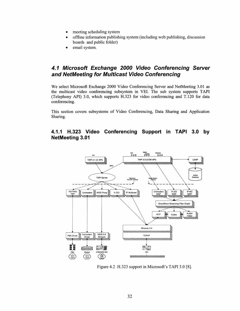
Figure 4.2 H.323 support in Microsoft's TAPI 3.0 [8].
32
4.1.1 H.323 Video ConferencingNetMeeting 3.01
Support in TAPI 3.0 by
R= - - ---- - -- - OMM

The H.323 Telephony Service Provider is the implementation of H.323 in TAPI 3.0. TheH.323 Telephony Service Provider allows TAPI-enabled applications to engage inmultimedia sessions with any H.323-compliant terminal on the local area network. Therelationship between TAPI 3.0 and H.323 is shown in Figure 4.2.
The architecture of H.323 Telephony Service Provider implemented by Microsoft is shownin Figure 4.3.
H.323 Conerncin Apliato
CN C~d C~.d cofrd
D~f LOAP-OrDk-h
Figure 4.3. Microsoft's H.323 Implementation in TAPI 3.0 [8].
4.1.2 IP Multicast Conferencing support in TAPI 3.0
33
Audl
Cwrw 4 S -,nlng W- Renckm SP-Wo"Gmph E3
CoCon
Sound Card Kmopn
C*"PbFtTP Fftw Codec Sound - -z
FNW
Whoook 2.0
Tcpnp

TAPI 3.0 supports IP Multicast Conferencing, which also requires support from Windows2000 as a multicast enabled platform. Figure 4.4 shows IP Multicast Conferencingarchitecture in TAPI 3.0.
cast Conferencing Appto
Colnml LDAPF T. k"
Figure 4.4 IP Multicast Conferencing in TAPI 3.0 [8].
SSL and SDP are used to ensure security in multicast video conferencing. The SessionDescription Protocol (SDP), which is used to describe the conference name, conferencepurpose, conference time, media type, media format, transport protocol, multicast addressand port, etc, is transferred using SSL between the video conferencing server and clients.The SDP Conference Key is used to encrypt the actual media stream before it is transferredusing RTP[9].
SDP Descriptor withConference Encryption Key LDAP
LayerIP
Layer
IEncryption Layer
Authentication: Windows NT Security SubsystemTransmission: Secure Sockets Layer (SSL)
(a) Distribution of SDP Conference Key
Media Stream
EnrytonLae
RPRTP Layer Layer
( SDP Conference Key)
(b) Encryption of Multicast Media Stream
Figure 4.5 Security in Multicast Video Conferencing [10].
34
RPC
TAPI Senvir
IP W.Alk"Y S-4- P(TSP) Media Skean,
Audo
DireolShoor Streanni; FAw Rarulanor SpeakeretGraph ON
N, Sound Card miawrierte
CaptureRTP Fifter
Fair
Wdmiock 2.0
TCPAP

4.1.3 T.120 Data Conferencing Support in TAPI 3.0 by NetMeeting3.01
Support for the T. 120 data conferencing standard also enables interoperability with otherT. 120-based products and services. The following features comprise multipoint dataconferencing:
Application sharing: A user can share a program running on one computer with otherparticipants in the conference. Participants can review the same data or information andsee the actions as the person sharing the application works on the program (for example,editing content or scrolling through information.) Participants can share Windows-basedapplications transparently without any special knowledge of the application capabilities.
The person sharing the application can choose to collaborate with other conferenceparticipants, and they can take turns editing or controlling the application. Only the personsharing the program needs to have the given application installed on their computer. Userscan also share their entire desktop to others in T. 120 data conferencing.
Shared ClipBoard The shared clipboard enables a user to exchange its contents with otherparticipants in a conference, using familiar cut, copy, and paste operations. For example, aparticipant can copy information from a local document and paste the contents into ashared application as part of group collaboration.
File Transfer: With the file transfer capability, a user can send a file in the background toone or all of the conference participants. When one user drags a file into the main window,the file is automatically sent to each person in the conference; they can then accept ordecline receipt. This file transfer capability is fully compliant with the T. 127 standard.
WhiteBoard: Multiple users can simultaneously collaborate using the whiteboard toreview, create, and update graphic information. The whiteboard is object-oriented (versuspixel-oriented), enabling participants to manipulate the contents by clicking and draggingwith the mouse. In addition, they can use a remote pointer or highlighting tool to point outspecific contents or sections of shared pages.
Chat: A user can type text messages to share common ideas or topics with otherconference participants or record meeting notes and action items as part of a collaborativeprocess. Participants in a conference can also use chat to communicate in the absence ofaudio support. A whisper feature lets a user have a separate, private conversation withanother person during a group chat session.
4.1.4 User Management in Video Conferencing
Microsoft Active Directory Server (ADS) is used in the Windows 2000 platform toprovide the universal user identification service. The Server manages user information,such as user name, password and so on. It also provides meeting information registry andaccess control in video conferencing via the Internet Locator Service (ILS) DynamicDirectory, which is a real-time server component in the Server.
35
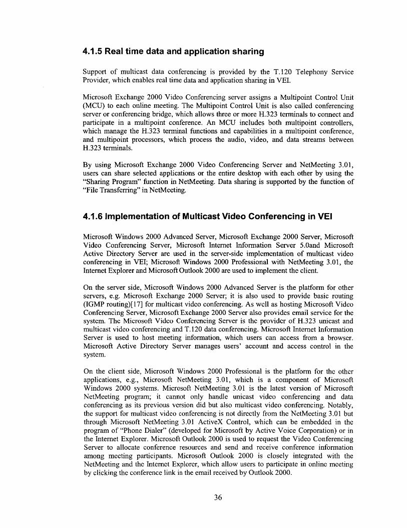
4.1.5 Real time data and application sharing
Support of multicast data conferencing is provided by the T.120 Telephony ServiceProvider, which enables real time data and application sharing in VEI.
Microsoft Exchange 2000 Video Conferencing server assigns a Multipoint Control Unit(MCU) to each online meeting. The Multipoint Control Unit is also called conferencingserver or conferencing bridge, which allows three or more H.323 terminals to connect andparticipate in a multipoint conference. An MCU includes both multipoint controllers,which manage the H.323 terminal functions and capabilities in a multipoint conference,and multipoint processors, which process the audio, video, and data streams betweenH.323 terminals.
By using Microsoft Exchange 2000 Video Conferencing Server and NetMeeting 3.01,users can share selected applications or the entire desktop with each other by using the"Sharing Program" function in NetMeeting. Data sharing is supported by the function of"File Transferring" in NetMeeting.
4.1.6 Implementation of Multicast Video Conferencing in VEI
Microsoft Windows 2000 Advanced Server, Microsoft Exchange 2000 Server, MicrosoftVideo Conferencing Server, Microsoft Internet Information Server 5.0and MicrosoftActive Directory Server are used in the server-side implementation of multicast videoconferencing in VEI; Microsoft Windows 2000 Professional with NetMeeting 3.01, theInternet Explorer and Microsoft Outlook 2000 are used to implement the client.
On the server side, Microsoft Windows 2000 Advanced Server is the platform for otherservers, e.g. Microsoft Exchange 2000 Server; it is also used to provide basic routing(IGMP routing)[ 17] for multicast video conferencing. As well as hosting Microsoft VideoConferencing Server, Microsoft Exchange 2000 Server also provides email service for thesystem. The Microsoft Video Conferencing Server is the provider of H.323 unicast andmulticast video conferencing and T. 120 data conferencing. Microsoft Internet InformationServer is used to host meeting information, which users can access from a browser.Microsoft Active Directory Server manages users' account and access control in thesystem.
On the client side, Microsoft Windows 2000 Professional is the platform for the otherapplications, e.g., Microsoft NetMeeting 3.01, which is a component of MicrosoftWindows 2000 systems. Microsoft NetMeeting 3.01 is the latest version of MicrosoftNetMeeting program; it cannot only handle unicast video conferencing and dataconferencing as its previous version did but also multicast video conferencing. Notably,the support for multicast video conferencing is not directly from the NetMeeting 3.01 butthrough Microsoft NetMeeting 3.01 ActiveX Control, which can be embedded in theprogram of "Phone Dialer" (developed for Microsoft by Active Voice Corporation) or inthe Internet Explorer. Microsoft Outlook 2000 is used to request the Video ConferencingServer to allocate conference resources and send and receive conference informationamong meeting participants. Microsoft Outlook 2000 is closely integrated with theNetMeeting and the Internet Explorer, which allow users to participate in online meetingby clicking the conference link in the email received by Outlook 2000.
36

The relationship of the above systems is illustrated in Figure 4.6.
(Platformfor otherservers and IGMP routing formulticast video coferencing) i(platform for other applications)
email clin41crosoft Exchante 200 Serer access control Microsoft Outlook 2000
tServer and platform for Vkdso Cordnci -- (Emall client and requests forServer) Microsoft Active Directory Server access conference resource allocation)- (User managmn and accesn 1
notiicton
access NetMeeting 3.01cont access control (Data and Video conferencing
Microsoft Exchange 2000 Videoprvd)Conferencing Server
(Date an deo Conferncng resource frnerequest conference -
management) Microsoft Internet Informat on Web basedserver -online
(Host for conference Information) Meeting Internet Explorer(Web browser and host for
Figure 4.6 The implementation of Multicast Video Conferencing in VEt
The configuration of the server is summarized as follows:1. create a domain for Windows 2000 Advanced Server,2. install Microsoft Active Directory Server, Microsoft Exchange 2000 Server,
Microsoft Internet Information Server on Windows 2000 Advanced Server,3. install Microsoft Exchange 2000 Video Conferencing Server on Windows
2000 Advanced Server,4. create users and store access control information for the users who will be the
video conferencing participants in Microsoft Active Directory Server,5. allocate IP resources for multicast video conferencing using Route And
Remote Service in Windows 2000 Advanced Server,6. create video conferencing resource in Exchange 2000 Video Conferencing
Server and assign the IP resource to it,7. create an email box for every user.
The configuration of the client is as follows:
1.2.
install Outlook 2000 on Windows 2000 Professional.create user profile on Outlook 2000 to log onto Exchange 2000 server usingthe account in Active Directory Server.
4.1.7 A Typical Session of Multicast Video Conferencing in VEI
Figure 4.7 illustrates a typical session of Multicast Video Conferencing implemented in
VEI:
37
Microsoft Windows ZW Professional - \

NetMeetingActiveX Control
Microsof OutlookPticipants2 0 NetMeeting
20Internet e ActiveX ControlExplorer -
InternetExplorer
Conferene 5 Micosoftr .WWW Server Microsoft Outlook
Microsoft Outlook 2
2000 3 Internet5 Explorer
6M f NetMMicrosoft change ActiveX
D2000 erver
Microsoft ActiveDirectory Server
Participant
eetingControl
Figure 4.7 A typical procedure of video conferencing in VEI
By using Microsoft Outlook 2000, the meeting initiator requestsMicrosoft Exchange 2000 Server Video Conferencing Server to allocatethe resources (virtual conferencing room) for the anticipated meetingand send notification to meeting participants (Figure 4.8).
Figure 4.8 Request for video conference by Microsoft Outlook 2000
After Microsoft Active Directory Server certifies the identification ofthe initiator, Exchange 2000 Video Conferencing Server allocates theresource for the meeting.
38
1.
2.

Exchange 2000 Server sends notification to all the meeting participants.Exchange 2000 Video Conferencing Server publishes conferenceinformation on Microsoft Internet Information Server (Figure 4.9).
Figure 4.9 Conference information published on Internet Information Server
Meeting participants attends the meeting on time by logging on to thevideo conferencing server using the Internet Explorer (Figure 4.10).
ul~n eu~~eweccould noe be established The )Aicrosoft Exchange muaicast client reqiresWzie2
60our higher and your network must be niuheicast enabled.
Figure 4.10. User logs onto Video Conferencing Server
Meeting participants transfer video streams and share data andapplications using the NetMeeting ActiveX Control embedded in theInternet Explorer (Figure 4.11).
39
3.4.
5.
6.

Figure 4.11. A multicast video conference participated in by three users
4.2 Instant Messaging in VEI
Instant Messaging is an important real time collaboration method. By using InstantMessaging, team members can obtain each other's online status, send short messages andinvite others to chat or attend an online meeting.
4.2.1 Implementation of Instant Messaging
In the implementation of Instant Messaging in VEI, Microsoft Windows 2000 AdvancedServer, Microsoft Exchange 2000 Server, and Microsoft Active Directory Server are usedon the server side; Microsoft MSN Messager is the client running on Windows 2000professional.
Microsoft MSN Messager provides the functions for online status checking, instantmessage exchange, and voice conversation. Microsoft MSN Messager is closely integratedwith Microsoft Exchange 2000 Server and Microsoft Active Directory Server, whichprovides the global directory service for Instant Messaging Service users.
The system diagram is shown in Figure 4.12.
40

Microsoft Windows 2000 Professional(platform for other applications)
Microsoft Windows 2000 Advanced Server(Platform for other servers)
Microsoft Active Directory Server access(User management and access control
control)
access control
Mlcrosoft Exchange 2000 Server(instant Message Store)
I-Log onto-
Figure 4.12 The implementation of Instant Messaging in VEI
The configuration of the server is summarized as follows:
1. create a domain for Windows 2000 Advanced Server,2. install Microsoft Active Directory Server and Microsoft Exchange 2000
Server on Windows 2000 Advanced Server,3. in Active Directory Server, create users and store access control information
for the users who will use the Instant Messaging Service,4. create instant message server in Exchange 2000 Server,5. assign instant message service for every user.
The configuration of the client is as follows:1. install Microsoft MSN Messager on Windows 2000 Professional,2. create user profile on Microsoft MSN Messager to log onto Exchange 2000
server using the account in Active Directory Server.
4.2.2 A Typical Session of Instant Messaging in VEI
Figure 4.13 illustrates a typical session of Instant Messaging implemented in VEI:
41
Microsoft MSN Messager
'11111 1 1

- users
Microsoft Active Microsoft xchangeDirectory Server 2000 server
userMicrosoft
Windows 2000 3
Advanced I
Server
-1 3
Microsoft xchange2000 .1erver
2
user
Microsoft ActiveDirectory Server
Figure 4.13 A typical session of Instant Messaging in VEI
1. Users log onto Microsoft Exchange 2000 Server using Microsoft MSNMessager (Figure 4.14).
Figure 4.14 User logs onto Exchange Server by MSN Messager
2. User checks other users' online status by querying Microsoft Exchange 2000Server and Microsoft Active Directory Server (Figure 4.15).
42

Figure 4.15. Check user's online status
3. Users exchange instant messages by Microsoft MSN Messager (Figure 4.16).
Figure 4.16. Exchange Instant Messages
43

4.3 Offline Information Publishing in VEI
Offline Information Publishing in VEI includes Web Publishing, Threaded DiscussionBoards and Public Folder Sharing.
After comparing Microsoft Exchange Server and IBM Lotus Domino Server [ 11][12][13],we choose IBM Lotus Domino Server for Web Publishing and Threaded DiscussionBoards, and Microsoft Exchange 2000 Server and Microsoft Outlook 2000 for PublicFolder sharing.
4.3.1 Web Publishing and Threaded Discussion
General information, such as the introduction of the consortium, is managed in the form ofstatic web pages. VEI's authorized users can upload documents, such as reports, meetingagendas and so on to the VEI website. These kinds of documents are stored in the databaseof IBM Lotus Domino Server.
IBM Lotus Domino Server has a web server backed with a powerful database. The LotusDomino Server provides templates for users to access database contents from its specificview and editor, Lotus Notes, or from a web browser directly. User can create documents,upload files and modify posted messages. IBM Lotus Domino Server itself provides usermanagement and access control. The Server records all the modifications with time tags.Each user's upload or post is one record in the Server's database. By indexing the databasecontent, the Server provides an easy way to search within all the posts by content orauthor.
IBM Lotus Domino Server also provides templates for threaded discussion. Threadeddiscussions are organized in the order of topic and time sequence.
4.3.2 Public Folder Sharing in VEI
Public Folder Sharing is an efficient tool for team members to share files and synchronizechanges of document in the form of team folder. By using Microsoft Outlook 2000, a usercan create a team folder easily on Microsoft Exchange 2000 Server and assign accesscontrol to other team colleagues to allow them to use the same folder.
The content in Public Folder can be any kind of document created by Microsoft Office2000.
4.4 Email in VEI
Email is the most frequently used collaboration tool in VEI. Microsoft Exchange 2000Server and Microsoft Outlook 2000 are used as the email server and email client.
44

4.5 Summary
Existing commercialized software systems from IBM and Microsoft are integrated toimplement VEI. In this way, VEI provides users multiple functionalities, not only inoffline but also in real time collaborations. Multicast video and data conferencing, instantmessaging, discussion boards and public folders are VEI's most important features.
45

46

Chapter 5. Distributed Meeting Scheduling System
5.1 Problem Statement of Meeting Scheduling
Before a conference, the meeting organizer needs to settle the meeting schedule. In atraditional conference it is always time-consuming for the meeting organizer to call everypotential participant to negotiate a feasible meeting schedule. We have built a distributedmeeting scheduling system to save the conference manager the burden.
5.1.1 What Is Meeting Scheduling in VEI?
Meeting scheduling is the procedure to find a time period for a meeting acceptable for allthe members in a group. There are three elements in meeting scheduling:
* a group of users (U = {u}). Some of the users can be required meeting
attendees (UR), the others can be optional users (UO).
* a meeting to be scheduled (M). The meeting has a length in time (Lm ) and
can only be allocated in s time period (TM ) .
* user s calendar information, which indicates a set of time slots({t, }) that can
be allocated for the meeting. Each t, has length (LM ) .
Thus, meeting scheduling in VEI is to find a time slot tM , which meets the following
constraints:
* t. has length LM0 t Me T
0 tM e {t,} for Vu c UR
5.1.2 A Typical Meeting Scheduling Procedure
In a typical procedure for scheduling a meeting, the meeting organizer might look in hiscalendar first and find a free date for the upcoming meeting, which seems to be acceptableto all the participants. Then the organizer may inform the participants and ask if the date ofthe meeting is in fact acceptable. Each participant will look in his own calendar to see if heis free during that period; if he is free, he will accept the meeting schedule and mark thatperiod as busy in his calendar; if not, he will reject the schedule and ask if the meeting canbe arranged for another period marked free in his calendar. If all the participants accept the
47
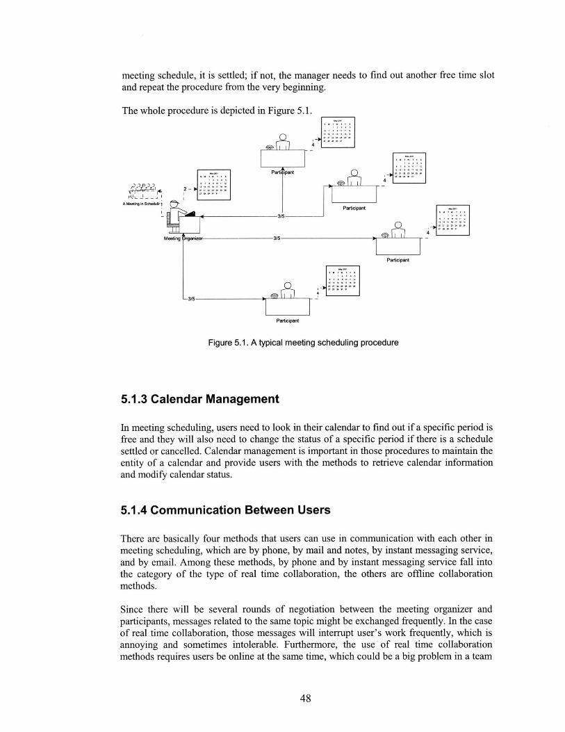
meeting schedule, it is settled; if not, the manager needs to find out another free time slotand repeat the procedure from the very beginning.
The whole procedure is depicted in Figure 5.1.
2 ,-Parts Ppant
A Meeig in Scledkiri Participant
4 -3/5
Participant
-3/ -
Participant
Figure 5.1. A typical meeting scheduling procedure
5.1.3 Calendar Management
In meeting scheduling, users need to look in their calendar to find out if a specific period isfree and they will also need to change the status of a specific period if there is a schedulesettled or cancelled. Calendar management is important in those procedures to maintain theentity of a calendar and provide users with the methods to retrieve calendar informationand modify calendar status.
5.1.4 Communication Between Users
There are basically four methods that users can use in communication with each other inmeeting scheduling, which are by phone, by mail and notes, by instant messaging service,and by email. Among these methods, by phone and by instant messaging service fall intothe category of the type of real time collaboration, the others are offline collaborationmethods.
Since there will be several rounds of negotiation between the meeting organizer andparticipants, messages related to the same topic might be exchanged frequently. In the caseof real time collaboration, those messages will interrupt user's work frequently, which isannoying and sometimes intolerable. Furthermore, the use of real time collaborationmethods requires users be online at the same time, which could be a big problem in a team
48
*~ ~ U L~ tr - -
whose members are in countries around the world with different time zones and differentworking hours.
In most cases, settling a meeting schedule is usually weeks ahead and not that urgent, sothe delay of offline collaboration methods is not a big issue. Offline collaboration is betterthan real time collaboration for communication between users in meeting scheduling.
5.2 Centralized System and Distributed System
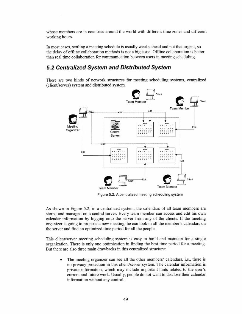
There are two kinds of network structures for meeting scheduling systems, centralized(client/server) system and distributed system.
Client
Team Member
- view_____ EtTeam
CentralServer
Client
Member
Edit
Edit
Client Edit
Team Member
0 2 Client
Team Member
Figure 5.2. A centralized meeting scheduling system
As shown in Figure 5.2, in a centralized system, the calendars of all team members arestored and managed on a central server. Every team member can access and edit his owncalendar information by logging onto the server from any of the clients. If the meetingorganizer is going to propose a new meeting, he can look in all the member's calendars onthe server and find an optimized time period for all the people.
This client/server meeting scheduling system is easy to build and maintain for a singleorganization. There is only one optimization in finding the best time period for a meeting.But there are also three main drawbacks in this centralized structure:
0 The meeting organizer can see all the other members' calendars, i.e., there isno privacy protection in this client/server system. The calendar information isprivate information, which may include important hints related to the user'scurrent and future work. Usually, people do not want to disclose their calendarinformation without any control.
49
MeetingOrganizerr
Edmet
-

* The system requires every user to access the central server with a relativelyhigh-speed network. Users need to access and edit their calendar informationin the central server frequently and the calendar information should be updatedquickly. A low speed network connection reduces the system performancedramatically.
0 In the case that a member is belonged to several groups, his calendarinformation has to be synchronized between several different servers. Thisalso makes the system more complicated.
Unlike a client/server system, a distributed system allows every user to manage his owncalendar independently. As shown in Figure 5.3, a distributed meeting scheduling systemis more like the natural structure illustrated in Figure 5.1.
Edit andlocal optimization
Ask for best fit time peroid Client
Team Member
.Edit and local >ptimization *-Return the best fit time period Team Member
Return the best fit time period dt and
2ocal -
Ask for best fit time period mization " " . " "
MeetingOrganizer
Retum the best fit time period
Return the beat fit time perod Edit and local optimization
Aak for best fit time period
-Ask for best it time period
Edit and local optimization CTeam Member
Team Member
Figure 5.3. A distributed meeting scheduling system
In the distributed meeting scheduling system, calendar information is stored and managedlocally for every team member, who does not need to publish his entire calendarinformation to others, even the meeting organizer. When a participant finds the proposedmeeting schedule does not fit him, he can give the meeting organizer additionalinformation about in what time periods he is free, or he can simply reject that meetingrequest. There is no central server in this case and nobody can get the other users' entirecalendar information.
The costs for using such a distributed meeting scheduling system are that additionaloptimization is required on every participant's side, more communication between meetingorganizer and participants is required and no global optimized solution is guaranteed.
50

Virtual Engineering Initiative is designed to support teams whose members are working indifferent countries all over the world. In the application of V42 Consortium, VEI has usersfrom several companies located in different countries. So it is very difficult to locate thecentral server to get a high speed connection between the clients and the server as requiredin the case of the centralized system; the distributed system design allows VEI's users tomanage their calendar information locally while protecting their privacy easily. Theadditional optimization and communication are handled by the system automaticallywithout interfering with users.
5.3 Summary
Traditional meeting scheduling is time consuming. A centralized meeting schedulingsystem cannot protect user's privacy and requires a high speed network connection fromeach client and the central server; a distributed system can solve the above problems easilybut requires more optimization and communication. VEI chooses the distributed system asits meeting scheduling system structure.
51

52

Chapter 6. Meeting Scheduler -- Software AgentApproach of Meeting Scheduling in VEI
Virtual Engineering Initiative is designed to support team whose members are working indifferent countries all over the world. Considering the low bandwidth network connectionand privacy constraints, VEI chooses the distributed system as its meeting schedulingsystem structure. VEI implements the system as a meeting scheduler with a software agentsystem. Every agent can manage the calendar information, optimize locally and negotiatemeeting schedules with others on behalf of its users.
6.1 User Case Diagram of Meeting Scheduler
The user case diagram of the Meeting Scheduler is illustrated in Figure 6.1. The MeetingScheduler interacts with its users to gather the information about the most desirablemeeting time configuration. After a user is invited to attend an online meeting, the MeetingScheduler acquires the user's calendar information from Calendar Storage and optimizeslocally to find the best time periods for the upcoming meeting. The result will be sent tothe meeting organizer through the email server.
User
Figure 6.1. User Case Diagram of Meeting Scheduler
6.2 The Elements of Meeting Schedule Optimization
In the problem of meeting scheduling explained in 5.1.1, we might find several free time
slots (t,,,) for a meeting request, which one should we assign the meeting to is the problem
of meeting schedule optimization.
53
Calendar Storage
Calendar nfrmation Storage
Meeting Scheduler
Ca meat(Calendar Information Management)
(Local Optimization insearching for free time slot)
(Communication with others using email)
Email Server
email exchange

By adding an additional parameter, the time preference, into 5.1.1, we obtain the elementsin meeting schedule optimization as follows,
* a group of users (U = {u}). Some of the users can be required meeting
attendees (UR ), the others can be optional users (UO ).
* a meeting to be scheduled (M). The meeting has a length in time (Lm) and
can only be allocated in s time period (TM ) .
* user's calendar information, which indicates a set of time slots( {t, }) that can
be allocated for the meeting. Each t, has length (LM).
" user's preference on the time slots (P = {p,1 })
The optimization of the meeting schedule is to find a time slot tM, which meets the
following constraints:
* tM has length LM
* tM Tm
StM G {t,} for Vu E UR
* tM = arg max {P}
6.3 Representation of Time Preference (P)
We use two values, static preference value p 0IL and dynamic preference value pltL to
calculate a user's time preference pL on a time slot t, .
The static preference value p 0tL is assigned for half an hour in a day of the week, the set
of preference values is PO , PO = {p 0 tL }. Since different meeting might have different
length (Lm), we can calculate the corresponding POt based on PO . For example, we
can simply average p0's in period tm to get the time preference.
If we have pOl 's on Monday from 9:00 to 11:00 as in Table 6.1,
Table 6.1 Static Time Preference On Monday Morningtime Mon 9:00-9:30am Mon 9:30- Mon 10:00- Mon 10:30-
10:00am 10:30am 11:00am
p0 tL 1 2 8 6
we can get PO, for LM = 60 min as in Table 6.2,
54
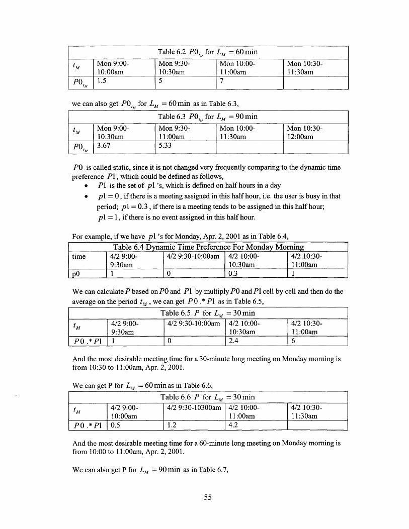
Table 6.2 POt for LM = 60 min
tM Mon 9:00- Mon 9:30- Mon 10:00- Mon 10:30-10:00am 10:30am 11:00am 11:30am
po,, 1.5 5 7
we can also get PO for LM = 60 min as in Table 6.3,
Table 6.3 PO,, for LM = 90 min
tM Mon 9:00- Mon 9:30- Mon 10:00- Mon 10:30-
____10:30am 1 1:00am j11:30amn 12:00amP0, 3.67 5.33
PO is called static, since it is not changed very frequently comparing to the dynamic timepreference P1, which could be defined as follows,
* P1 is the set of p 1 's, which is defined on half hours in a day
* pl = 0, if there is a meeting assigned in this half hour, i.e. the user is busy in that
period; pl = 0.3 , if there is a meeting tends to be assigned in this half hour;
pl = 1, if there is no event assigned in this half hour.
For example, if we have p1 's for Monday, Apr. 2, 2001 as in Table 6.4,
Table 6.4 Dynamic Time Preference For Monday Morningtime 4/2 9:00- 4/2 9:30-10:00am 4/2 10:00- 4/2 10:30-
9:30am 10:30am 11:00amp0 1 0 0.3 1
We can calculate P based on PO and P1 by multiply PO and P1 cell by cell and then do the
average on the period tM, we can get P 0 .* P1 as in Table 6.5,
Table 6.5 P for Lm = 30 min
tM 4/2 9:00- 4/2 9:30-10:00am 4/2 10:00- 4/2 10:30-9:30am 10:30am 11:00am
PO .*P 1 0 2.4 6
And the most desirable meeting time for a 30-minute long meeting on Monday morning isfrom 10:30 to 11:00am, Apr. 2, 2001.
We can get P for LM= 60minas in Table 6.6,
Table 6.6 P for LM = 30 min
tM 4/2 9:00- 4/2 9:30-10300am 4/2 10:00- 4/2 10:30-10:00am 11:00am 11:30am
P0 .* PI 0.5 1.2 4.2
And the most desirable meeting time for a 60-minute long meeting on Monday morning isfrom 10:00 to 11:00am, Apr. 2, 2001.
We can also get P for Lm = 90 min as in Table 6.7,
55

Table 6.7 P for LM = 90 min
tM 4/2 9:00- 4/2 9:30-11:00am 4/2 10:00- 4/2 10:30-10:30am 11:30am 12:00am
PO .*P1 1.33 2.8
And the most desirable meeting time for a 90-minute long meeting on Monday morning isfrom 9:30 to 11:00am, Apr. 2, 2001.
6.4 Conflict Handling
Users can also set a threshold for the time preference, such as pt = 5, which means if
PM < pt for a time period tM , then the meeting cannot be scheduled from t, so the forth
constraint in the meeting schedule optimization is modified to
t = arg max({p; p > pt})
In some cases, there will be no valid time slot tM found, i.e., there is no solution for
scheduling of current meeting. The scheduler can chOose to alter the schedule of settledmeetings to find out a solution or just reject the request for assigning time slots for thecurrent meeting. If all the required attendees accept the meeting request, the meeting canbe settled; if any of the required attendees rejects the meeting request, the meeting cannotbe settled even though all the optional attendees accept the request.
6.5 Propagation Of Change Of The Meeting Schedule
Sometimes, a meeting might be changed or cancelled after it has been assigned a timeperiod. So the meeting scheduler needs to propagate the change of schedule to the othersinvolved in the same event.
For the cancellation of a meeting, the meeting scheduler for the organizer just needs tosend out request for the participants to free the assigned time slots, which may affect theuser's ongoing meeting scheduling. For a change of the meeting schedule, it needs to askthe participants to free the assigned time slots first, and then begin a new round of meetingschedule negotiations.
6.6 Implementation of Meeting Scheduler in VEI
To simplify the implementation, we build Meeting Scheduler on top of Microsoft Outlook2000. Meeting Scheduler is programmed in Visual C++ embedded with Outlook 2000ActiveX control, through which Meeting Scheduler can easily manage the user's calendarinformation stored in Microsoft Exchange 2000 Server and communicate with others byemail.
56

The system diagram is depicted in Figure 6.2.
Microsoft Windows 20DO Professional(platform for other applications)
Meeting Schoduler(User Preference Management ad
Optimization and MessageGoneration)
Ebidded With
Microsoft Outlook 2000(Calendar Information Client
and Email Cleint)
access_-contrd
-Log onto
rosoft Windows 2000 Advanced Server(Platform for other servers)
Microsoft Active Directory Se(User Management and Access
Control)
access control
Microsoft Exchange 2000 Server(Calendar Information Store
and Email Server)
Figure 6.2 The implementation of Meeting Scheduler in VEI
The user can input his static time preference in Meeting Scheduler, as illustrated in Figure6.3. The static time preference values range from 0 to 7. The smaller the preference value,
Figure 6.3. The user inputs his static preference in Meeting Scheduler
57

the less desirable the user tends to assign a meeting in that half hour. The user's timepreference is stored as a journal item in Outlook 2000's Journal folder.
Figure 6.4 Negotiations on meeting time are stored as journal items in Outlook.
As illustrated in Figure 6.4, the negotiations of meeting scheduling are stored as a journalitem in Outlook 2000. The Meeting Scheduler can monitor its user's email box and filterout the emails for meeting request, which are placed through Outlook 2000, by checkingthe flag of olMeetingStatus[15][16]. Then the Meeting Scheduler retrieves the email,optimizes locally based on its user's calendar information and time preference. If themeeting request is accepted, the Meeting Scheduler will add the meeting into its user'scalendar, move the request into a specific folder and create a item in its user's Outlook2000's Journal folder for logging. If the request cannot be accepted, the Meeting Schedulerwill send a reject email to the initiator with its user's most desirable time slots attached.
6.7 Sequence Diagram for Meeting Scheduler in VEI
The sequence diagram for Meeting Scheduler is illustrated in Figure 6.5:
1. Meeting initiator requests to allocate an online meeting using Outlook 2000.2. Outlook 2000 asks Exchange 2000 Server to allocate resources for the online
meeting.3. Exchange 2000 Server allocates resources for the meeting, send notification to
the initiator, and sends email to the other meeting participants.4. The participant's Meeting Scheduler keeps monitoring the upcoming meeting
invitation through Outlook 2000.
58

5. The participant's Outlook 2000 retrieves the meeting invitation from itsExchange 2000 Server.
6. The participant's Meeting Scheduler retrieves its owner's calendar informationthrough Outlook 2000.
7. The participant's Outlook 2000 retrieves calendar information from itsExchange 2000 Server.
8. The participant's Meeting Scheduler optimizes based on its owner's calendarinformation and find out if the invitation is acceptable.
9. The participant's Meeting Scheduler sends "Accept" notification to theinitiator, and sends notification to its owner.
10. The participant's "Accept" notification is sent through his Outlook 2000 andExchange 2000 Server and initiator's Exchange 2000 Server.
11. The Initiator's Meeting Scheduler keeps monitoring the invitation replies fromparticipants.
12. The Initiator's Meeting Scheduler retrieves each participant's "Accept"notification by Outlook 2000.
13. The Initiator's Meeting Scheduler checks the reply and finds out that theinvitation is accepted, then it generates a notification to its owner to informhim that the meeting schedule is settled.
The Meeting scheduler is proactive, since it can monitor its user's coming email and filterout the information related to meeting schedule negotiation; it is intelligent, since it canfind the most desirable time slot for its user; it is cooperative, since it can negotiatemeeting schedules with others. Meeting Scheduler is a software agent system.
6.8 Conclusion
The design and implementation of Meeting Scheduler, a software agent system to solve themeeting-scheduling problem, is given in this chapter. Meeting Scheduler can find the mostdesirable time slot for a given meeting request and negotiate with other agents to find a
near-global-optimized solution on behalf of its users.
59

t ~ Meeting Scheduler Outlook 200 Exchange 2000 Server Exchange 2000 Server Outlook 200 Meeting Scheduler t
Meeting Organizer allocate Meeting resource Meeting Participant
request allocation of online meeting submit send email notification monitor emailinitiatemoioeal I emeeting request to meetin artici an cmenivglo
return allocated .meeting invitationprompt notification of allocation by email ~ meeting resourc ationT and modify
calendar information retrieveretrieve en dar ino
calendar informati )n"Jl........................
Operaion TOptimization
Operationsend optimization _ Accept
monior ceck eplyforresult to initiatormonitor check reply for send optimization send notificationinvitation reply meeting invitation result to initiatort we
accept retrieve Negotiation
retrieve invitation rep y invitation reply
check replyIie invitation is accepted.send notification to user
T
Figure 6.5. Sequence Diagram of Meeting Scheduler

Chapter 7. Conclusion
Virtual Engineering Initiative is an intelligent web collaboration system, which is designedto meet the collaboration needs of a globally located team in the procedure of engineeringdesign. The team might have members working on the same project but living around theworld with different time zones and thus having different working hours. Thecollaborations among the team members are intensive and important to the success of theproject. Virtual Engineering Initiative can fulfill the requirements of fast and efficientcollaborations among the team, whereas traditional collaboration methods, such as mail,telephone and so on, cannot.
Virtual Engineering Initiative has ten main components, which can be further classifiedinto four functional groups: video conferencing, information publishing, instant messagingand meeting scheduling. Video conferencing enable users to collaborate in a virtualconference room. Database backed web publishing enables users to publish informationbefore, in and after conference. Web Based Discussion Boards, Email, News Group, BBSand Public Folder enable users share their information when offline. Instant Messagingallows users to send messages to others in real time.
Existing commercialized software systems from IBM and Microsoft are integrated toimplement VEI. In this way, VEI provides users multiple functionalities, not only inoffline but also in real-time collaborations. Multicast video and data conferencing, instant
messaging, discussion boards and public folders are VEI's most important features.
As an application, VEI provides video conferencing, information publishing before, duringand after the conference, and meeting scheduling to assist the 42V Consortium in itsweekly meetings.
Traditional meeting scheduling is time consuming. A centralized meeting schedulingsystem cannot protect user's privacy and requires a high-speed network connection fromeach client and the central server; a distributed system can solve the above problems easilybut requires more optimization and communication. VEI chooses the distributed system asits meeting scheduling system structure and implements it as Meeting Scheduler. MeetingScheduler adds an intelligent feature into the system by automating the procedure ofmeeting scheduling.
The design and implementation of Meeting Scheduler, a software agent system to solve themeeting-scheduling problem, is given in this thesis. Meeting Scheduler can find the mostdesirable time slot for a given meeting request and negotiate with other agents to find anear-global-optimized solution on behalf of its users.
Virtual Engineering Initiative has been successfully used by the 42V Consortium as theircollaboration platform in the design procedure of a new electronic architecture.
The current Virtual Engineering Initiative system is mainly based on Microsoft Window2000 platform, clients have to be a Win-Intl system to participate in the collaboration. Thefuture work of this research might include expanding the system onto other platforms, suchas Macintosh, Linux and Unix; improving the sound quality in the video conferencing for
61

low bandwidth network connections; and exploring the scalability of VEI to serve largeteams.
62
REFERENCE
[1] DesGroseilliers/Rennecker, "MIT/Ford Virtual Engineering Initiative 42 VoltAdvanced Automotive Electrical Systems Virtual Meeting Minutes December 15, 1998,"http://auto.mit.edu/vei/play.nsf/d295e8432872a849852564f700203bfe/1 14b288ff4clced38825681 f0068a49e/$FILE/Dec_15_VirtualMeeting.pdf
[2] Real Networks, "Realplayer Top 5 issues,"http://service.real.com/help/faq/top5/rpfiletypes.html
[3] Jane Hunter, Varuni Witana, Mark Antoniades, "A Review of Video Streaming overthe The Internet," DSTC Technical Report TR97-10, August 1997
[4] Microsoft, "MS Windows NetMeeting 3 Resource Kit"
[5] P. Cherriman, L. Hanzo and R. Lucas, "ARQ-assisted H261 and H263-basedProgrammable Video Transceivers," Departmental Research Journal 1995/6 (online)
[6]Protocols.com, "H.323," http://www.protocols.com/pbook/h323.htm
[7] Chuck Semeria and Tom Maufer, "Introduction to IP Multicast Routing,"http://www.3com.com/nsc/501303.html
[8] Microsoft Corporation, "IP Telephony with TAPI 3.0 White Paper," April 1999,http://www.microsoft.com/technet/win2000/win2ksrv/technote/tapi30. asp
[9] Jon Crowcroft, Mark Handley, Ian Wakeman, "Internetworking Multimedia," UCLPress, 1998
[10] Jayaprakash Pasala, "Information Management In Virtual Engineering," 1999.6
[11] ZDLabs , "Microsoft Exchange 5.5 vs. Lotus Domino R5 POP and SMTPPerformance Test," Dec. 1999
[12] Microsoft Corporation, "A Comparison Between Exchange 2000 And Lotus Notes R5Microsoft Windows 2000 Integration,"http://www.microsoft.com/exchange/productioninfo/R5Winlntegration.htm
[13] Microsoft Exchange Server Production Group, "A Comparison to LotusNotes/Domino R5, collaboration and web allocations," Oct. 2000
[14] Chunlei Liu, "Multimedia Over IP,"http://www.cis.ohio-state.edu/-cliu/ipmultimedia/
[15]Mindy Martin, "Automating Microsoft Outlook 98," August 21, 19998

[16]Microsoft Corporation, "Microsoft Office 97/ Visual Basic Programmer's Guide,"Feb. 3, 1997
[17] Microsoft Corporation, "Microsoft Multicast IP & Windows Media TechnologiesDeployment," Jan. 17, 2000.
26- 64