an1809:minimal boot sequence for executing compiled c...
TRANSCRIPT
This document describes the procedures necessary to initialize a PowerPC™ processorsuccessfully and begin executing programs compiled using the embedded PowerPCapplication interface (EABI). The items discussed in this document have been tested forMPC603e™, MPC750, and MPC7400 microprocessors. The methods and source codepresented in this document may work unmodified on similar devices as well.
This document contains the following topics:
• Part I, “Overview,” provides a summary of the conditions and exceptions for the procedures described in this document.
• Part II, “Processor Initialization,” provides information on the general setup of the processor registers, caches, and MMU.
• Part III, “EABI Compliance,” discusses aspects of the EABI that apply directly to preparing to jump into a compiled C program.
• Part IV, “Sample Boot Sequence,” describes the basic operation of the boot sequence and the many options of configuration, explains in detail a sample configurable boot and how the code may be modified for use in different environments, and discusses the compilation procedure using the supporting GNU build environment.
• Part V, “Source Files,” contains the complete source code for the files ppcinit.S, ppcinit.h, reg_defs.h, ld.script, and Makefile.
• Part VI, “Revision History,” contains a table that lists the document revisions since its inception.
Part I Overview
The procedures discussed in this document perform only the minimum amount of worknecessary to execute a user program. The sample boot sequence is designed to run fromsystem reset. It does not contain exception handling facilities for other exceptions, althoughthe code is located so that it doesn’t interfere with exception space. This allows users who wishto provide exception handling to add exception code without modifying this source. Inaddition, this code only handles processor setup. It does not initialize any peripheral devicesbecause it is designed to be run on instruction set simulators, test cards, or small evaluationboards. No input/output interface is provided. Results are obtained by looking at data saved inmemory via hardware debuggers or simulator commands.
Application Note
AN1809Rev. 1.2, 11/2003
Minimal Boot Sequence for Executing Compiled C Programs on PowerPC™ Devices
Fre
esc
ale
Se
mic
on
du
cto
r, I
Freescale Semiconductor, Inc.
For More Information On This Product, Go to: www.freescale.com
nc
...
Minimal Boot Sequence for Executing Compiled C Programs on PowerPC™ Devices
General Initialization General Initialization
The sample boot sequence uses a memory management unit (MMU) to provide basic access protection forthe ROM and RAM regions of memory via block address translation (BAT). The more advanced features ofthe MMU, which provide support for paging and segmentation, are not utilized.
The sample boot sequence provided should be linked with a user program to create a ROM image. Thisimage is then loaded into a ROM device located at the default system reset vector. The sample boot sequencehandles the task of relocating the code and data from ROM to RAM where necessary and then allows theuser program to execute. Upon completion, the boot sequence saves timing information for the user codeand branches to the invalid opcode exception vector.
Part II Processor Initialization
This section describes the state of the processor at power-up, the MMU, the caches, and the EABI registerinitialization.
2.1 General Initialization
At power-up, the processor is in a minimal state, with most features, such as caching and address translation,disabled. External interrupts, the machine check exception, and floating-point exceptions are also disabled.On most systems, the processor starts up in big-endian mode with the exception prefix set to 0xFFF0_0000.This means that upon system reset (exception vector 0x0100), the processor executes code beginning at0xFFF0_0100.
The code located at the system reset vector must handle system initialization. Exception vectors for theprocessor are located at increments of 0x0000_0100 from the vector table start address. Because theinitialization code must fit between the allocated hard reset exception space between 0xFFF0_0100 and0xFFF0_01FF, it is customary for the reset code to branch to an address beyond the end of the exceptiontable’s allocated space and execute the instruction sequence located there. Addresses starting at0xFFF0_0100 and ending at 0xFFF0_3000 are reserved for the exception vector table.
A typical initialization sequence performs the necessary processor setup or hardware-specific initialization,and then enables exceptions. This includes external interrupts, the machine check exception, and floating-point exceptions. In addition, if the vector table is to be relocated once the hardware setup is complete, theexception prefix (IP) bit of the machine state register (MSR) must be changed to reflect the new location ofthe vector table (0x0000_0100 to 0x0000_3000).
2.2 Memory Management Unit
A boot program will need to set up the MMU if memory management is required. Using the MMU totranslate memory addresses allows the programmer to specify protections and access controls for individualregions of memory. For a minimal system with four or fewer memory regions, it is sufficient to use blockaddress translation (BAT) to perform a rudimentary mapping. For more complex systems, the segmentregisters and page tables need to be initialized. This document only addresses the minimal configurationusing the BAT registers.
The MMU information provided in this document is included for convenience and is not complete. For moreinformation about using BAT registers and the MMU, refer to
The Programming Environments Manual
.
When using the MMU to provide address translation via the BAT registers, each region of memory in thesystem should have an associated BAT mapping. These mappings allow the programmer to specify options
Fre
esc
ale
Se
mic
on
du
cto
r, I
Freescale Semiconductor, Inc.
For More Information On This Product, Go to: www.freescale.com
nc
...
Minimal Boot Sequence for Executing Compiled C Programs on PowerPC™ Devices
Memory Management Unit
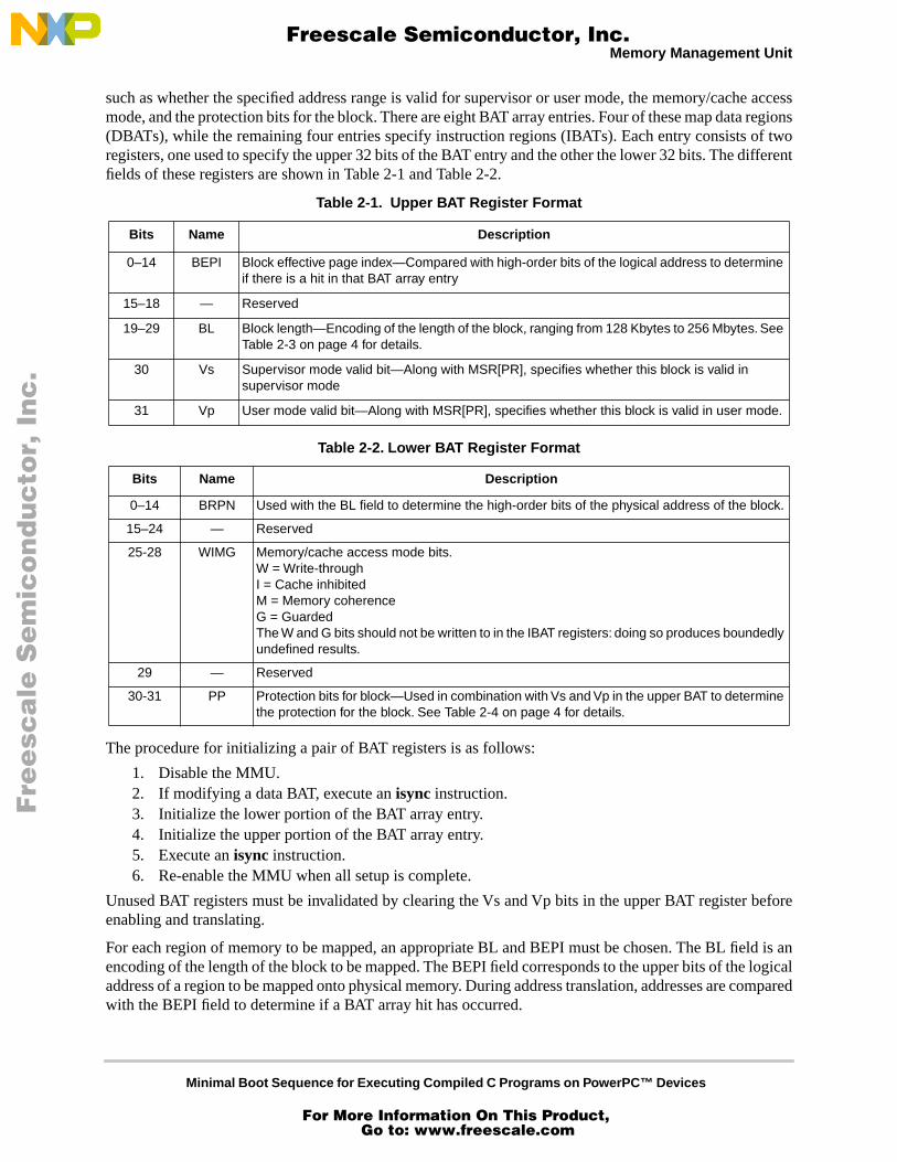
such as whether the specified address range is valid for supervisor or user mode, the memory/cache accessmode, and the protection bits for the block. There are eight BAT array entries. Four of these map data regions(DBATs), while the remaining four entries specify instruction regions (IBATs). Each entry consists of tworegisters, one used to specify the upper 32 bits of the BAT entry and the other the lower 32 bits. The differentfields of these registers are shown in Table 2-1 and Table 2-2.
The procedure for initializing a pair of BAT registers is as follows:
1. Disable the MMU.2. If modifying a data BAT, execute an
isync
instruction.3. Initialize the lower portion of the BAT array entry.4. Initialize the upper portion of the BAT array entry.5. Execute an
isync
instruction.6. Re-enable the MMU when all setup is complete.
Unused BAT registers must be invalidated by clearing the Vs and Vp bits in the upper BAT register beforeenabling and translating.
For each region of memory to be mapped, an appropriate BL and BEPI must be chosen. The BL field is anencoding of the length of the block to be mapped. The BEPI field corresponds to the upper bits of the logicaladdress of a region to be mapped onto physical memory. During address translation, addresses are comparedwith the BEPI field to determine if a BAT array hit has occurred.
Table 2-1. Upper BAT Register Format
Bits Name Description
0–14 BEPI Block effective page index—Compared with high-order bits of the logical address to determine if there is a hit in that BAT array entry
15–18 — Reserved
19–29 BL Block length—Encoding of the length of the block, ranging from 128 Kbytes to 256 Mbytes. See Table 2-3 on page 4 for details.
30 Vs Supervisor mode valid bit—Along with MSR[PR], specifies whether this block is valid in supervisor mode
31 Vp User mode valid bit—Along with MSR[PR], specifies whether this block is valid in user mode.
Table 2-2. Lower BAT Register Format
Bits Name Description
0–14 BRPN Used with the BL field to determine the high-order bits of the physical address of the block.
15–24 — Reserved
25-28 WIMG Memory/cache access mode bits.W = Write-throughI = Cache inhibitedM = Memory coherenceG = GuardedThe W and G bits should not be written to in the IBAT registers: doing so produces boundedly undefined results.
29 — Reserved
30-31 PP Protection bits for block—Used in combination with Vs and Vp in the upper BAT to determine the protection for the block. See Table 2-4 on page 4 for details.
Fre
esc
ale
Se
mic
on
du
cto
r, I
Freescale Semiconductor, Inc.
For More Information On This Product, Go to: www.freescale.com
nc
...
Minimal Boot Sequence for Executing Compiled C Programs on PowerPC™ Devices
Memory Management Unit Memory Management Unit
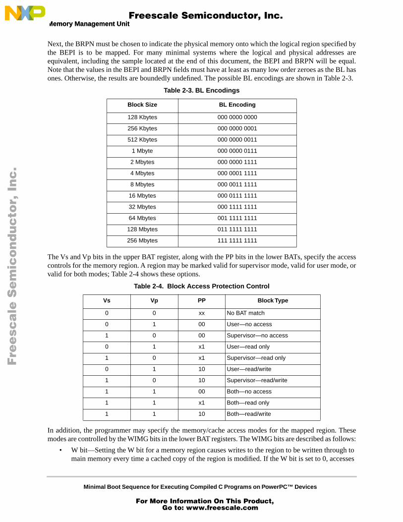
Next, the BRPN must be chosen to indicate the physical memory onto which the logical region specified bythe BEPI is to be mapped. For many minimal systems where the logical and physical addresses areequivalent, including the sample located at the end of this document, the BEPI and BRPN will be equal.Note that the values in the BEPI and BRPN fields must have at least as many low order zeroes as the BL hasones. Otherwise, the results are boundedly undefined. The possible BL encodings are shown in Table 2-3.
The Vs and Vp bits in the upper BAT register, along with the PP bits in the lower BATs, specify the accesscontrols for the memory region. A region may be marked valid for supervisor mode, valid for user mode, orvalid for both modes; Table 2-4 shows these options.
In addition, the programmer may specify the memory/cache access modes for the mapped region. Thesemodes are controlled by the WIMG bits in the lower BAT registers. The WIMG bits are described as follows:
• W bit—Setting the W bit for a memory region causes writes to the region to be written through to main memory every time a cached copy of the region is modified. If the W bit is set to 0, accesses
Table 2-3. BL Encodings
Block Size BL Encoding
128 Kbytes 000 0000 0000
256 Kbytes 000 0000 0001
512 Kbytes 000 0000 0011
1 Mbyte 000 0000 0111
2 Mbytes 000 0000 1111
4 Mbytes 000 0001 1111
8 Mbytes 000 0011 1111
16 Mbytes 000 0111 1111
32 Mbytes 000 1111 1111
64 Mbytes 001 1111 1111
128 Mbytes 011 1111 1111
256 Mbytes 111 1111 1111
Table 2-4. Block Access Protection Control
Vs Vp PP Block Type
0 0 xx No BAT match
0 1 00 User—no access
1 0 00 Supervisor—no access
0 1 x1 User—read only
1 0 x1 Supervisor—read only
0 1 10 User—read/write
1 0 10 Supervisor—read/write
1 1 00 Both—no access
1 1 x1 Both—read only
1 1 10 Both—read/write
Fre
esc
ale
Se
mic
on
du
cto
r, I
Freescale Semiconductor, Inc.
For More Information On This Product, Go to: www.freescale.com
nc
...
Minimal Boot Sequence for Executing Compiled C Programs on PowerPC™ Devices
Caches
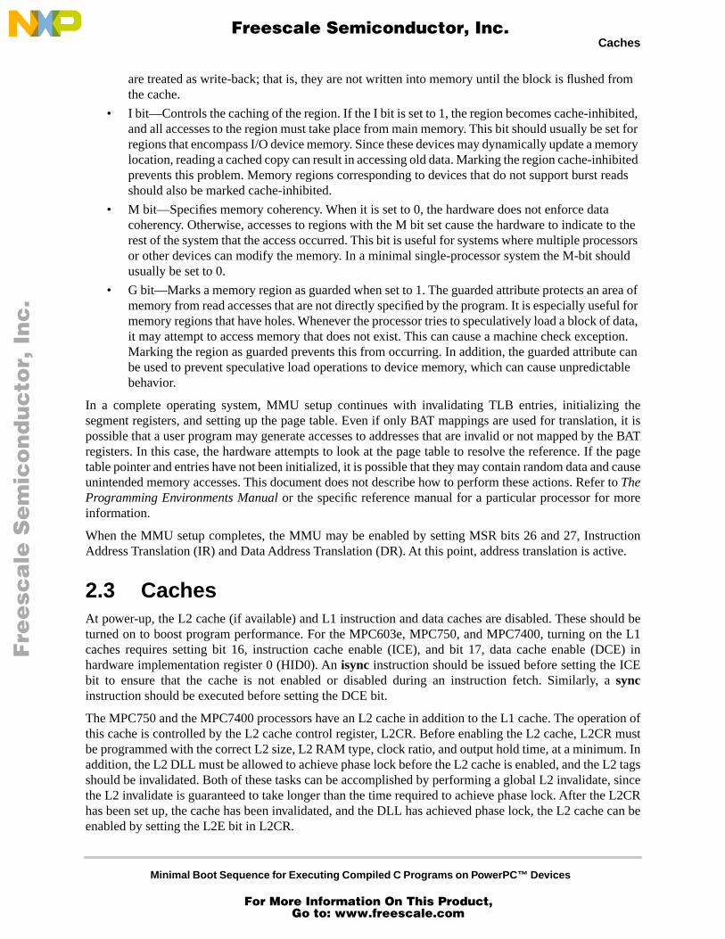
are treated as write-back; that is, they are not written into memory until the block is flushed from the cache.
• I bit—Controls the caching of the region. If the I bit is set to 1, the region becomes cache-inhibited, and all accesses to the region must take place from main memory. This bit should usually be set for regions that encompass I/O device memory. Since these devices may dynamically update a memory location, reading a cached copy can result in accessing old data. Marking the region cache-inhibited prevents this problem. Memory regions corresponding to devices that do not support burst reads should also be marked cache-inhibited.
• M bit—Specifies memory coherency. When it is set to 0, the hardware does not enforce data coherency. Otherwise, accesses to regions with the M bit set cause the hardware to indicate to the rest of the system that the access occurred. This bit is useful for systems where multiple processors or other devices can modify the memory. In a minimal single-processor system the M-bit should usually be set to 0.
• G bit—Marks a memory region as guarded when set to 1. The guarded attribute protects an area of memory from read accesses that are not directly specified by the program. It is especially useful for memory regions that have holes. Whenever the processor tries to speculatively load a block of data, it may attempt to access memory that does not exist. This can cause a machine check exception. Marking the region as guarded prevents this from occurring. In addition, the guarded attribute can be used to prevent speculative load operations to device memory, which can cause unpredictable behavior.
In a complete operating system, MMU setup continues with invalidating TLB entries, initializing thesegment registers, and setting up the page table. Even if only BAT mappings are used for translation, it ispossible that a user program may generate accesses to addresses that are invalid or not mapped by the BATregisters. In this case, the hardware attempts to look at the page table to resolve the reference. If the pagetable pointer and entries have not been initialized, it is possible that they may contain random data and causeunintended memory accesses. This document does not describe how to perform these actions. Refer to
TheProgramming Environments Manual
or the specific reference manual for a particular processor for moreinformation.
When the MMU setup completes, the MMU may be enabled by setting MSR bits 26 and 27, InstructionAddress Translation (IR) and Data Address Translation (DR). At this point, address translation is active.
2.3 Caches
At power-up, the L2 cache (if available) and L1 instruction and data caches are disabled. These should beturned on to boost program performance. For the MPC603e, MPC750, and MPC7400, turning on the L1caches requires setting bit 16, instruction cache enable (ICE), and bit 17, data cache enable (DCE) inhardware implementation register 0 (HID0). An
isync
instruction should be issued before setting the ICEbit to ensure that the cache is not enabled or disabled during an instruction fetch. Similarly, a
sync
instruction should be executed before setting the DCE bit.
The MPC750 and the MPC7400 processors have an L2 cache in addition to the L1 cache. The operation ofthis cache is controlled by the L2 cache control register, L2CR. Before enabling the L2 cache, L2CR mustbe programmed with the correct L2 size, L2 RAM type, clock ratio, and output hold time, at a minimum. Inaddition, the L2 DLL must be allowed to achieve phase lock before the L2 cache is enabled, and the L2 tagsshould be invalidated. Both of these tasks can be accomplished by performing a global L2 invalidate, sincethe L2 invalidate is guaranteed to take longer than the time required to achieve phase lock. After the L2CRhas been set up, the cache has been invalidated, and the DLL has achieved phase lock, the L2 cache can beenabled by setting the L2E bit in L2CR.
Fre
esc
ale
Se
mic
on
du
cto
r, I
Freescale Semiconductor, Inc.
For More Information On This Product, Go to: www.freescale.com
nc
...
Minimal Boot Sequence for Executing Compiled C Programs on PowerPC™ Devices
EABI Register Initialization EABI Register Initialization
Caution should be exercised when enabling the caches for certain hardware configurations. If there aredevices on the board that do not support burst reads, then the caches should not be enabled until the MMUhas been set up and enabled to mark these regions as cache-inhibited. Otherwise, the processor will attemptto burst read from these devices to fill the cache and possibly cause system errors. For these cases, the cachesshould be disabled whenever the MMU is disabled.
Note that simply enabling the caches is not sufficient to ensure that the caches will be used if the MMU isenabled. Memory regions where the user data resides should be mapped as non-cache-inhibited in order tomake use of the cache. See Section 2.2, “Memory Management Unit,” for more information on mappingmemory regions.
2.4 EABI Register Initialization
In order for user applications to run correctly, registers specified by the Embedded Application BinaryInterface (EABI) must be set up. This is handled by the __eabi() startup code and the code that executesprior to entry into main(). The sample boot sequence provides a simple __eabi() that initializes registersGPR2 and GPR13. GPR1 is initialized prior to the call to main() by the init sequence. Part III, “EABICompliance,” describes these registers and the other EABI register conventions in more detail.
Part III EABI Compliance
The EABI specifies the system interface for compiled programs. The EABI is based on the
System VApplication Binary Interface
and the
PowerPC™ Processor Supplement
. For general ABI documentation,refer to these documents, as well as the
PowerPC™ Embedded Application Binary Interface
. This documentonly includes aspects of the EABI that apply directly to preparing to jump into a compiled C program.
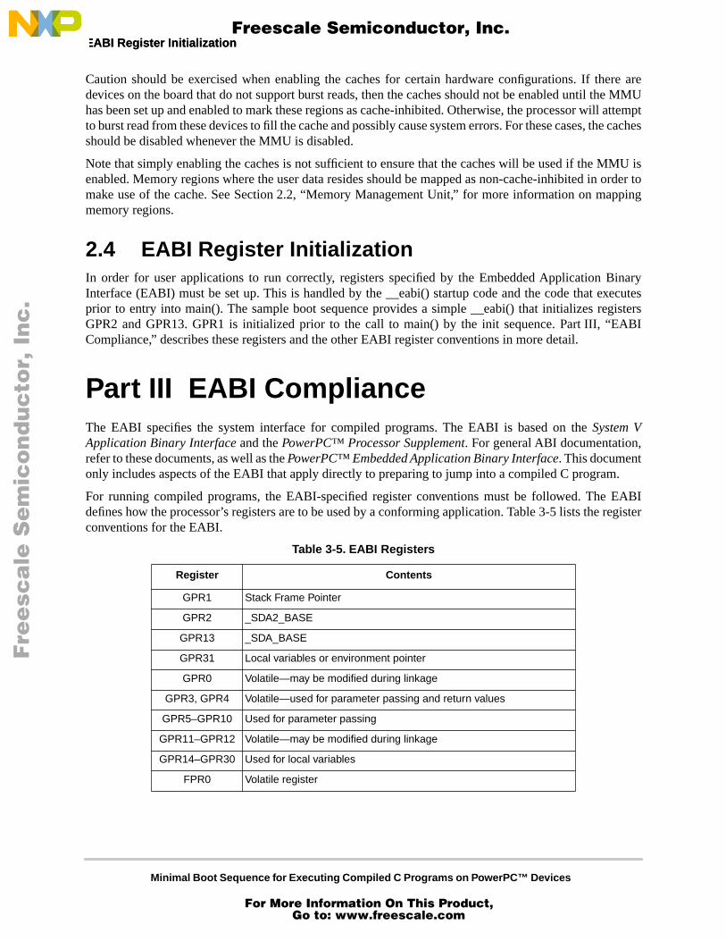
For running compiled programs, the EABI-specified register conventions must be followed. The EABIdefines how the processor’s registers are to be used by a conforming application. Table 3-5 lists the registerconventions for the EABI.
Table 3-5. EABI Registers
Register Contents
GPR1 Stack Frame Pointer
GPR2 _SDA2_BASE
GPR13 _SDA_BASE
GPR31 Local variables or environment pointer
GPR0 Volatile—may be modified during linkage
GPR3, GPR4 Volatile—used for parameter passing and return values
GPR5–GPR10 Used for parameter passing
GPR11–GPR12 Volatile—may be modified during linkage
GPR14–GPR30 Used for local variables
FPR0 Volatile register
Fre
esc
ale
Se
mic
on
du
cto
r, I
Freescale Semiconductor, Inc.
For More Information On This Product, Go to: www.freescale.com
nc
...

Minimal Boot Sequence for Executing Compiled C Programs on PowerPC™ Devices
EABI Register Initialization
The symbols _SDA_BASE and _SDA2_BASE are defined during linking. They specify the locations of thesmall data areas. A program must load these values into GPR13 and GPR2, respectively, before accessingprogram data.
The small data areas contain part of the data of the executable. They hold a number of variables that can beaccessed within a 16-bit signed offset of _SDA_BASE or _SDA2_BASE. References to these variables areperformed through references to GPR13 and GPR2 by the user program. Typically, the small data areascontain program variables that are less than or equal to 8 bytes in size, although this differs by compiler. Thevariables in SDA2 are read-only.
Before executing user code, the startup code must also set up the stack pointer in GPR1. This pointer mustbe 8-byte aligned for the EABI (as opposed to 16-byte aligned for ABI) and should point to the lowestallocated valid stack frame. The stack grows toward lower addresses, so its location should be selected sothat it does not grow into data or bss areas.
Much of the required EABI register setup is accomplished through a call to __eabi(). The user does not callthis function directly. Instead, the compiler inserts the call to __eabi() at the beginning of main() in the userprogram. Most compile environments provide an __eabi() function that is automatically linked with userprograms. Unfortunately, this standard __eabi() is often designed to work with a particular operating systemor environment. Because the processor is using the source in this application note, a minimal __eabi()function is supplied to handle these specific requirements.
The remainder of the registers are listed for completeness and are not modified by the minimal boot code.They may be modified by the user program.
Part IV Sample Boot Sequence
The sample boot sequence in this section completes minimal processor setup and executes a user program.It performs only processor setup (no peripheral devices), and leaves external interrupts disabled. It isdesigned for use with test cards, evaluation boards, or processor simulators where the developer can directlyview the contents of memory to verify correct program execution. This code sequence is designed to takethe place of the traditional crt0 module, as well as to provide hardware initialization normally performed bythe operating system.
The basic operation of the boot sequence is as follows:
1. Invalidate the BAT entries.2. If the processor has an L2, program L2CR and perform a global L2 invalidate.3. Set up the BAT registers to provide address translation and protection.4. Invalidate all TLB entries.5. Turn on address translation.6. Relocate the text, data, and bss sections from ROM to RAM.
FPR1 Volatile—used for parameter passing and return values
FPR2–FPR8 Volatile—used for parameter passing
FPR9–FPR13 Volatile registers
FPR14–FPR31 Used for local variables
Table 3-5. EABI Registers (continued)
Register Contents
Fre
esc
ale
Se
mic
on
du
cto
r, I
Freescale Semiconductor, Inc.
For More Information On This Product, Go to: www.freescale.com
nc
...

Minimal Boot Sequence for Executing Compiled C Programs on PowerPC™ Devices
Configurable Options Configurable Options
7. Enable the L1 and L2 caches, if present.8. Place the user code main entry address in SRR0.9. Put the MSR value for the user program into SRR1.10. Save the return address in the link register.11. Initialize the time base register to 0.12. Set up a stack pointer in GPR1 for the user program.13. Execute
rfi. This executes the user program by jumping to the address stored in SRR0. Before running the user code, a compiler-inserted call to __eabi() sets up EABI registers GPR2 and GPR13.
14. Save the time base register values into memory (useful for timing benchmarks).15. Branch to invalid op vector at 0xFFF0_0700 to indicate completion.
This procedure may be modified or configured to match the desired configuration.
4.1 Configurable Options
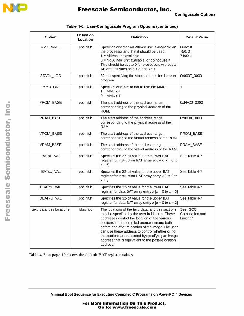
The design of the sample boot sequence allows it to be easily configurable. The many options defined in theheader files allow the user to choose how the code should execute. These options are summarized inTable 4-6.
Table 4-6. User-Configurable Program Options
OptionDefinition Location
Definition Default Value
USER_ENTRY ppcinit.h Specifies the name of the entry point in the user C program. Corresponds to main() but isn’t named main() due to possible compiler problems.
test_main
ICACHE_ON ppcinit.h Specifies whether to turn on the Instruction cache. 1 = icache on0 = icache off
1
DCACHE_ON ppcinit.h Specifies whether to turn on the data cache1 = dcache on0 = dcache off
1
L2CACHE_ENABLE ppcinit.h Specify whether to use the L2 cache.1 = L2 cache on0 = L2 cache offThis should be set to 0 for processors that don’t have an L2 cache, such as 603e
603e: 0750: 17400: 1
L2_INIT ppcinit.h L2CR configuration values with the L2E (L2 Enable) bit turned off. Specifies the appropriate L2 size, clock ratio, RAM type, and hold time. For the user’s convenience, #defines of the various options are provided in the file reg_defs.h. The default is set for a 0.5 MB burst RAM L2 cache with a clock divisor of 2 and a hold time of 0.5 nS.
(L2CR_L2SIZ_HM | L2CR_L2CLK_2 | L2CR_L2RAM_BURST | L2CR_L2OH_5)
L2_ENABLE ppcinit.h L2CR register value with L2 configuration values set and the L2 cache enabled (L2E set).
(L2_INIT | L2CR_L2E)
Fre
esc
ale
Se
mic
on
du
cto
r, I
Freescale Semiconductor, Inc.
For More Information On This Product, Go to: www.freescale.com
nc
...
Minimal Boot Sequence for Executing Compiled C Programs on PowerPC™ Devices
Configurable Options
Table 4-7 on page 10 shows the default BAT register values.
VMX_AVAIL ppcinit.h Specifies whether an AltiVec unit is available on the processor and that it should be used.1 = AltiVec unit available0 = No Altivec unit available, or do not use itThis should be set to 0 for processors without an AltiVec unit such as 603e and 750.
603e: 0750: 07400: 1
STACK_LOC ppcinit.h 32 bits specifying the stack address for the user program
0x0007_0000
MMU_ON ppcinit.h Specifies whether or not to use the MMU. 1 = MMU on0 = MMU off
1
PROM_BASE ppcinit.h The start address of the address range corresponding to the physical address of the ROM.
0xFFC0_0000
PRAM_BASE ppcinit.h The start address of the address range corresponding to the physical address of the RAM.
0x0000_0000
VROM_BASE ppcinit.h The start address of the address range corresponding to the virtual address of the ROM.
PROM_BASE
VRAM_BASE ppcinit.h The start address of the address range corresponding to the virtual address of the RAM.
PRAM_BASE
IBATxL_VAL ppcinit.h Specifies the 32-bit value for the lower BAT register for instruction BAT array entry x [x = 0 to x = 3]
See Table 4-7
IBATxU_VAL ppcinit.h Specifies the 32-bit value for the upper BAT register for instruction BAT array entry x [x = 0 to x = 3]
See Table 4-7
DBATxL_VAL ppcinit.h Specifies the 32-bit value for the lower BAT register for data BAT array entry x [x = 0 to x = 3]
See Table 4-7
DBATxU_VAL ppcinit.h Specifies the 32-bit value for the upper BAT register for data BAT array entry x [x = 0 to x = 3]
See Table 4-7
text, data, bss locations ld.script The locations of the text, data, and bss sections may be specified by the user in ld.script. These addresses control the location of the various sections in the compiled program image both before and after relocation of the image. The user can use these address to control whether or not the sections are relocated by specifying an image address that is equivalent to the post-relocation address.
See “GCC Compilation and Linking.”
Table 4-6. User-Configurable Program Options (continued)
OptionDefinition Location
Definition Default Value
Fre
esc
ale
Se
mic
on
du
cto
r, I
Freescale Semiconductor, Inc.
For More Information On This Product, Go to: www.freescale.com
nc
...

Minimal Boot Sequence for Executing Compiled C Programs on PowerPC™ Devices
Configurable Options Configurable Options
Each of these options can be configured in order to customize the boot sequence for a particular application.The configurable boot sequence contains #define statements that can be combined to easily create BAT entryvalues. For example, the default entry for the upper instruction BAT 1 specifies a 32-Mbyte block size, validuser mode, valid supervisor mode, with a BEPI of 0x0000_0000. This entry can be formed using the headerfile define statements as follows: IBAT1U_VAL = (VRAM_BASE | BAT_VALID_USER |BAT_VALID_SUPERVISOR | BAT_BL_32M). Refer to the source file for ppcinit.h at the end of thisdocument for details.
Table 4-7. Default BAT Register Values
Register Value Description Region
IBAT0L 0xFFC0_0022 BRPN = 1111 1111 1100 000WIMG = 0100 PP = 10 (read/write)
ROM
IBAT0U 0xFFC0_007F BEPI = 1111 1111 1100 000BL = 0000 0011 111 (4 Mbytes)Vs = 1 (valid for supervisor)Vp = 1 (valid for user)
ROM
IBAT1L 0x0000_0002 BRPN = 0000 0000 0000 000WIMG = 0000PP = 10 (read/write)
RAM
IBAT1U 0x0000_03FF BEPI = 0000 0000 0000 000BL = 0001 1111 111 (32 Mbytes)Vs = 1 (valid for supervisor)Vp = 1 (valid for user)
RAM
IBAT2L 0x0000_0000 BAT_NO_ACCESS NONE
IBAT2U 0x0000_0000 BAT_INVALID NONE
IBAT3L 0x0000_0000 BAT_NO_ACCESS NONE
IBAT3U 0x0000_0000 BAT_INVALID NONE
DBAT0L 0xFFC0_0022 BRPN = 1111 1111 1100 000WIMG = 0100PP = 10 (read/write)
ROM
DBAT0U 0xFFC0_007F BEPI = 1111 1111 1100 000BL = 0000 0011 111 (4 Mbytes)Vs = 1 (valid for supervisor)Vp = 1 (valid for user)
ROM
DBAT1L 0x0000_0002 BRPN = 0000 0000 0000 000WIMG = 0000 PP = 10 (read/write)
RAM
DBAT1U 0x0000_03FF BEPI = 0000 0000 0000 000BL = 0001 1111 111 (32 Mbytes)Vs = 1 (valid for supervisor)Vp = 1 (valid for user)
RAM
DBAT2L 0x0000_0000 BAT_NO_ACCESS NONE
DBAT2U 0x0000_0000 BAT_INVALID NONE
DBAT3L 0x0000_0000 BAT_NO_ACCESS NONE
DBAT3U 0x0000_0000 BAT_INVALID NONE
Fre
esc
ale
Se
mic
on
du
cto
r, I
Freescale Semiconductor, Inc.
For More Information On This Product, Go to: www.freescale.com
nc
...
Minimal Boot Sequence for Executing Compiled C Programs on PowerPC™ Devices
General Initialization
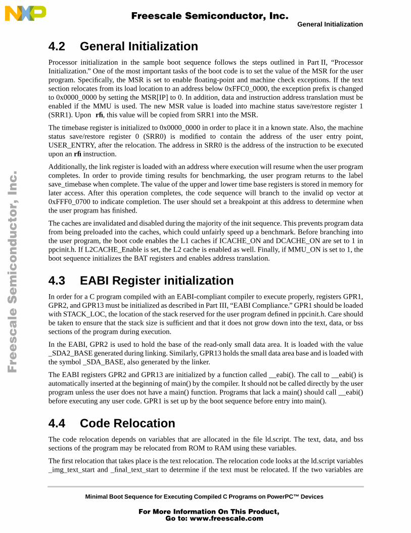
4.2 General Initialization
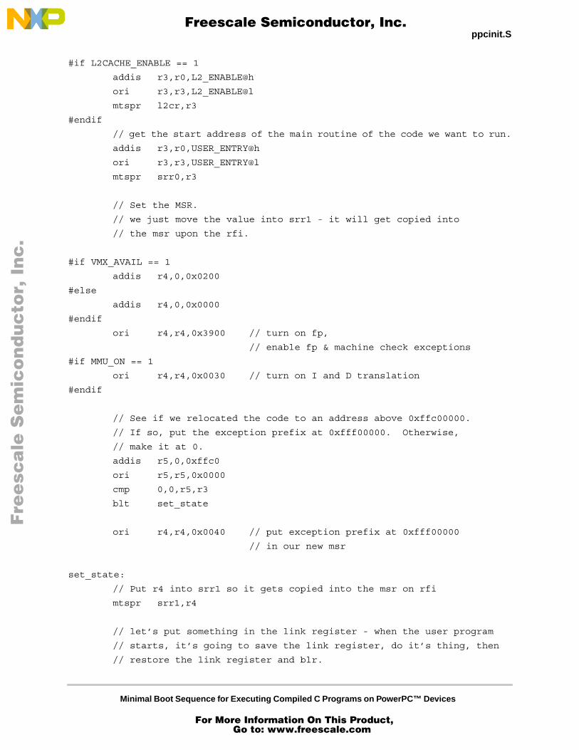
Processor initialization in the sample boot sequence follows the steps outlined in Part II, “ProcessorInitialization.” One of the most important tasks of the boot code is to set the value of the MSR for the userprogram. Specifically, the MSR is set to enable floating-point and machine check exceptions. If the textsection relocates from its load location to an address below 0xFFC0_0000, the exception prefix is changedto 0x0000_0000 by setting the MSR[IP] to 0. In addition, data and instruction address translation must beenabled if the MMU is used. The new MSR value is loaded into machine status save/restore register 1(SRR1). Upon
rfi
, this value will be copied from SRR1 into the MSR.
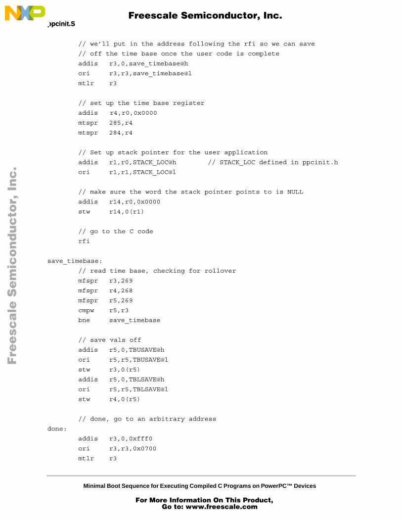
The timebase register is initialized to 0x0000_0000 in order to place it in a known state. Also, the machinestatus save/restore register 0 (SRR0) is modified to contain the address of the user entry point,USER_ENTRY, after the relocation. The address in SRR0 is the address of the instruction to be executedupon an
rfi
instruction.
Additionally, the link register is loaded with an address where execution will resume when the user programcompletes. In order to provide timing results for benchmarking, the user program returns to the labelsave_timebase when complete. The value of the upper and lower time base registers is stored in memory forlater access. After this operation completes, the code sequence will branch to the invalid op vector at0xFFF0_0700 to indicate completion. The user should set a breakpoint at this address to determine whenthe user program has finished.
The caches are invalidated and disabled during the majority of the init sequence. This prevents program datafrom being preloaded into the caches, which could unfairly speed up a benchmark. Before branching intothe user program, the boot code enables the L1 caches if ICACHE_ON and DCACHE_ON are set to 1 inppcinit.h. If L2CACHE_Enable is set, the L2 cache is enabled as well. Finally, if MMU_ON is set to 1, theboot sequence initializes the BAT registers and enables address translation.
4.3 EABI Register initialization
In order for a C program compiled with an EABI-compliant compiler to execute properly, registers GPR1,GPR2, and GPR13 must be initialized as described in Part III, “EABI Compliance.” GPR1 should be loadedwith STACK_LOC, the location of the stack reserved for the user program defined in ppcinit.h. Care shouldbe taken to ensure that the stack size is sufficient and that it does not grow down into the text, data, or bsssections of the program during execution.
In the EABI, GPR2 is used to hold the base of the read-only small data area. It is loaded with the value_SDA2_BASE generated during linking. Similarly, GPR13 holds the small data area base and is loaded withthe symbol _SDA_BASE, also generated by the linker.
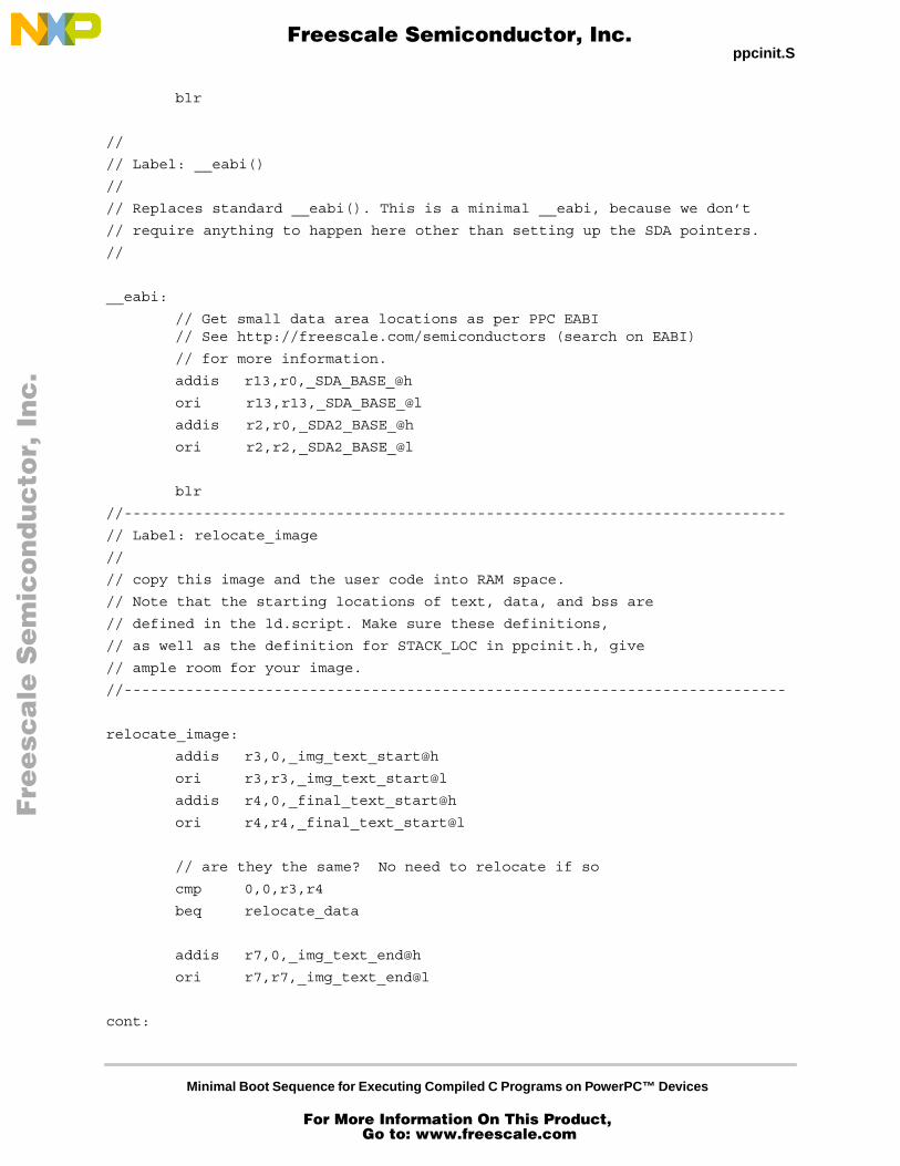
The EABI registers GPR2 and GPR13 are initialized by a function called __eabi(). The call to __eabi() isautomatically inserted at the beginning of main() by the compiler. It should not be called directly by the userprogram unless the user does not have a main() function. Programs that lack a main() should call __eabi()before executing any user code. GPR1 is set up by the boot sequence before entry into main().
4.4 Code Relocation
The code relocation depends on variables that are allocated in the file ld.script. The text, data, and bsssections of the program may be relocated from ROM to RAM using these variables.
The first relocation that takes place is the text relocation. The relocation code looks at the ld.script variables_img_text_start and _final_text_start to determine if the text must be relocated. If the two variables are
Fre
esc
ale
Se
mic
on
du
cto
r, I
Freescale Semiconductor, Inc.
For More Information On This Product, Go to: www.freescale.com
nc
...

Minimal Boot Sequence for Executing Compiled C Programs on PowerPC™ Devices
GCC Compilation and Linking GCC Compilation and Linking
equal, then no text relocation occurs. This typically speeds up execution in a simulated environment, andwhen the user program to be run is fairly simple. If the user program is large or performs large numbers ofiterations, execution may be speeded by moving the text from ROM to RAM if ROM accesses are slow.
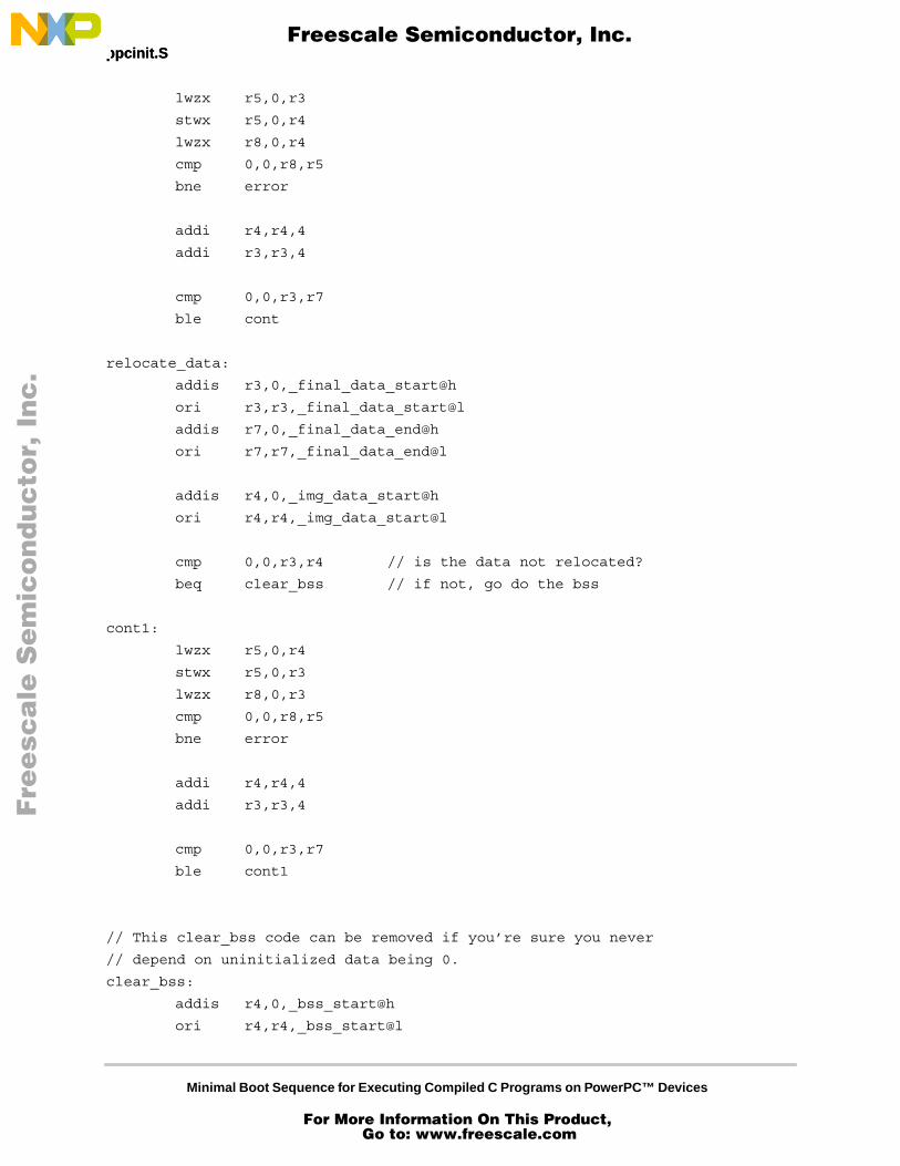
The start address of the section to be copied is stored in the symbol _img_text_start defined in ld.script. Thelength of the copy is determined using the symbol _img_text_end also defined in ld.script. The programstarts copying at _img_text_start and copies data to _final_text_start until it reaches the address_img_text_end.
Next, the data and bss sections may be relocated. For standard systems where the boot program exists in aread-only ROM, these sections must be moved so they can be modified by the user program. If the code isnot initially located in a ROM, or if the ROM is writeable, then these sections do not need to be relocated.The ROM image location of the data section is stored in the symbol _img_data_start, defined in ld.script. Itwill be relocated to the address defined in _final_data_start. If _img_data_start and _final_data_start are notequal, the relocation program starts copying from _img_data_start to _final_data_start. When the copy-toaddress is equal to _final_data_end, defined in ld.script, the copy is complete. If _img_data_start and_final_data_start are equal, the program skips the data copy.
The bss section is not actually copied since it only holds uninitialized data. Instead, the region starting at_bss_start and ending at _bss_end, both defined in ld.script, is initialized to all zeroes. This code may becommented out for programs which do not depend on zero-filled bss.
The user may control the ROM image and relocation addresses of the different sections by modifying thefile ld.script, as specified in Section 4.5, “GCC Compilation and Linking.”
4.5 GCC Compilation and Linking
The compilation and linking procedure for a standalone bootable program is fairly complex. The compiledprogram should not include standard libraries or startup code, and needs to be in a format that can be copiedinto a simulated or real ROM device or memory component. Most importantly, the code needs to be locatedat a specific absolute start point so that it begins execution on system reset. In addition, the executable needsto be built so that references to symbols and variables refer to the location of variables after the relocationto RAM (if any) has occurred. Most of this work is accomplished through the use of a linker script.
Note that this document refers to the target of the build as a “ROM image.” Whether this image is actuallyloaded into a ROM component or some other simulated or real memory device is implementationdependent.
The compilation procedure described in this application note uses the GNU cross-compiler version 2.8.1 (ldversion 2.9.1) which is free and publicly available from many different sources on the internet. The GNUmake utility and the GNU assembler and linker are also used. Other versions of the GNU tools may workas well.
The transition from .S and .c files to .o files is accomplished using gcc -c :
ppcinit.o: ppcinit.h ppcinit.S
$(CC) -c ppcinit.S
test.o: test.c
$(CC) -c test.c
$(CC) must be defined as the path to the cross-compiler. (See Part V, “Source Files,” Section 5.5,“Makefile.”) Note that the assembly source file is named
ppcinit.S as opposed to ppcinit.s. This causes thepreprocessor
to run and strip out the C++ style comments. In the makefile, all references to test should be
Fre
esc
ale
Se
mic
on
du
cto
r, I
Freescale Semiconductor, Inc.
For More Information On This Product, Go to: www.freescale.com
nc
...
Minimal Boot Sequence for Executing Compiled C Programs on PowerPC™ Devices
GCC Compilation and Linking
changed to match the name of the user program to be linked with the boot program. The build command fortest should be changed to specify the appropriate dependencies and build options.
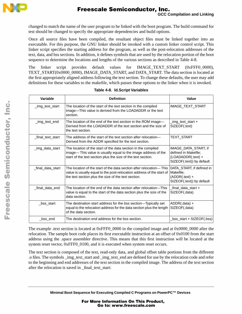
Once all source files have been compiled, the resultant object files must be linked together into anexecutable. For this purpose, the GNU linker should be invoked with a custom linker control script. Thislinker script specifies the starting address for the program, as well as the post-relocation addresses of thetext, data, and bss sections. In addition, it defines symbols that are used by the relocation portion of the bootsequence to determine the locations and lengths of the various sections as described in Table 4-8.
The linker script provides default values for IMAGE_TEXT_START (0xFFF0_0000),TEXT_START(0x0000_0000), IMAGE_DATA_START, and DATA_START. The data section is located atthe first appropriately aligned address following the text section. To change these defaults, the user may adddefinitions for these variables to the makefile, which passes these options to the linker when it is invoked.
The example .text section is located at 0xFFF0_0000 in the compiled image and at 0x0000_0000 after therelocation. The sample boot code places its first executable instruction at an offset of 0x0100 from the startaddress using the .space assembler directive. This means that this first instruction will be located at thesystem reset vector, 0xFFF0_0100, and it is executed when system reset occurs.
The text section is composed of the text, read-only data, and global offset table portions from the different.o files. The symbols _img_text_start and _img_text_end are defined for use by the relocation code and referto the beginning and end addresses of the text section in the compiled image. The address of the text sectionafter the relocation is saved in _final_text_start:
Table 4-8. ld.Script Variables
Variable Definition Value
_img_text_start The location of the start of the text section in the compiled image—This value is derived from the LOADADDR or the text section.
IMAGE_TEXT_START
_img_text_end The location of the end of the text section in the ROM image— Derived from the LOADADDR of the text section and the size of the text section.
_img_text_start + SIZEOF(.text)
_final_text_start The address of the start of the text section after relocation— Derived from the ADDR specified for the text section.
TEXT_START
_img_data_start The location of the start of the data section in the compiled image— This value is usually equal to the image address of the start of the text section plus the size of the text section.
IMAGE_DATA_START, if defined in Makefile; (LOADADDR(.text) + SIZEOF(.text)) by default
_final_data_start The location of the start of the data section after relocation— This value is usually equal to the post-relocation address of the start of the text section plus the size of the text section.
DATA_START, if defined in Makefile;(ADDR(.text) + SIZEOF(.text)) by default
_final_data_end The location of the end of the data section after relocation—This value is equal to the start of the data section plus the size of the data section.
_final_data_start + SIZEOF(.data)
_bss_start The destination start address for the bss section—Typically set equal to the relocation address for the data section plus the length of the data section.
ADDR(.data) + SIZEOF(.data)
_bss_end The destination end address for the bss section. _bss_start + SIZEOF(.bss)
Fre
esc
ale
Se
mic
on
du
cto
r, I
Freescale Semiconductor, Inc.
For More Information On This Product, Go to: www.freescale.com
nc
...
Minimal Boot Sequence for Executing Compiled C Programs on PowerPC™ Devices
GCC Compilation and Linking GCC Compilation and Linking
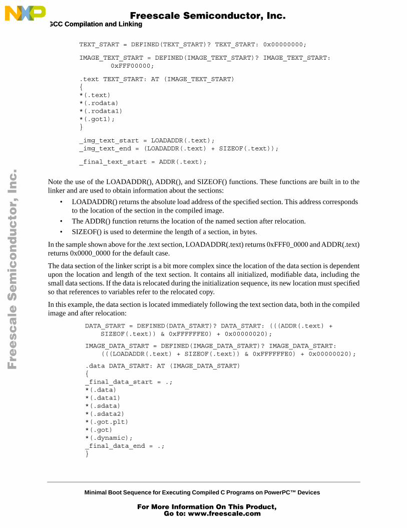
TEXT_START = DEFINED(TEXT_START)? TEXT_START: 0x00000000;
IMAGE_TEXT_START = DEFINED(IMAGE_TEXT_START)? IMAGE_TEXT_START:0xFFF00000;
.text TEXT_START: AT (IMAGE_TEXT_START){*(.text)*(.rodata)*(.rodata1)*(.got1);}
_img_text_start = LOADADDR(.text);_img_text_end = (LOADADDR(.text) + SIZEOF(.text));
_final_text_start = ADDR(.text);
Note the use of the LOADADDR(), ADDR(), and SIZEOF() functions. These functions are built in to thelinker and are used to obtain information about the sections:
• LOADADDR() returns the absolute load address of the specified section. This address corresponds to the location of the section in the compiled image.
• The ADDR() function returns the location of the named section after relocation.
• SIZEOF() is used to determine the length of a section, in bytes.
In the sample shown above for the .text section, LOADADDR(.text) returns 0xFFF0_0000 and ADDR(.text)returns 0x0000_0000 for the default case.
The data section of the linker script is a bit more complex since the location of the data section is dependentupon the location and length of the text section. It contains all initialized, modifiable data, including thesmall data sections. If the data is relocated during the initialization sequence, its new location must specifiedso that references to variables refer to the relocated copy.
In this example, the data section is located immediately following the text section data, both in the compiledimage and after relocation:
DATA_START = DEFINED(DATA_START)? DATA_START: (((ADDR(.text) + SIZEOF(.text)) & 0xFFFFFFE0) + 0x00000020);
IMAGE_DATA_START = DEFINED(IMAGE_DATA_START)? IMAGE_DATA_START:(((LOADADDR(.text) + SIZEOF(.text)) & 0xFFFFFFE0) + 0x00000020);
.data DATA_START: AT (IMAGE_DATA_START){_final_data_start = .;*(.data)*(.data1)*(.sdata)*(.sdata2)*(.got.plt) *(.got)*(.dynamic);_final_data_end = .;}
Fre
esc
ale
Se
mic
on
du
cto
r, I
Freescale Semiconductor, Inc.
For More Information On This Product, Go to: www.freescale.com
nc
...
Minimal Boot Sequence for Executing Compiled C Programs on PowerPC™ Devices
GCC Compilation and Linking
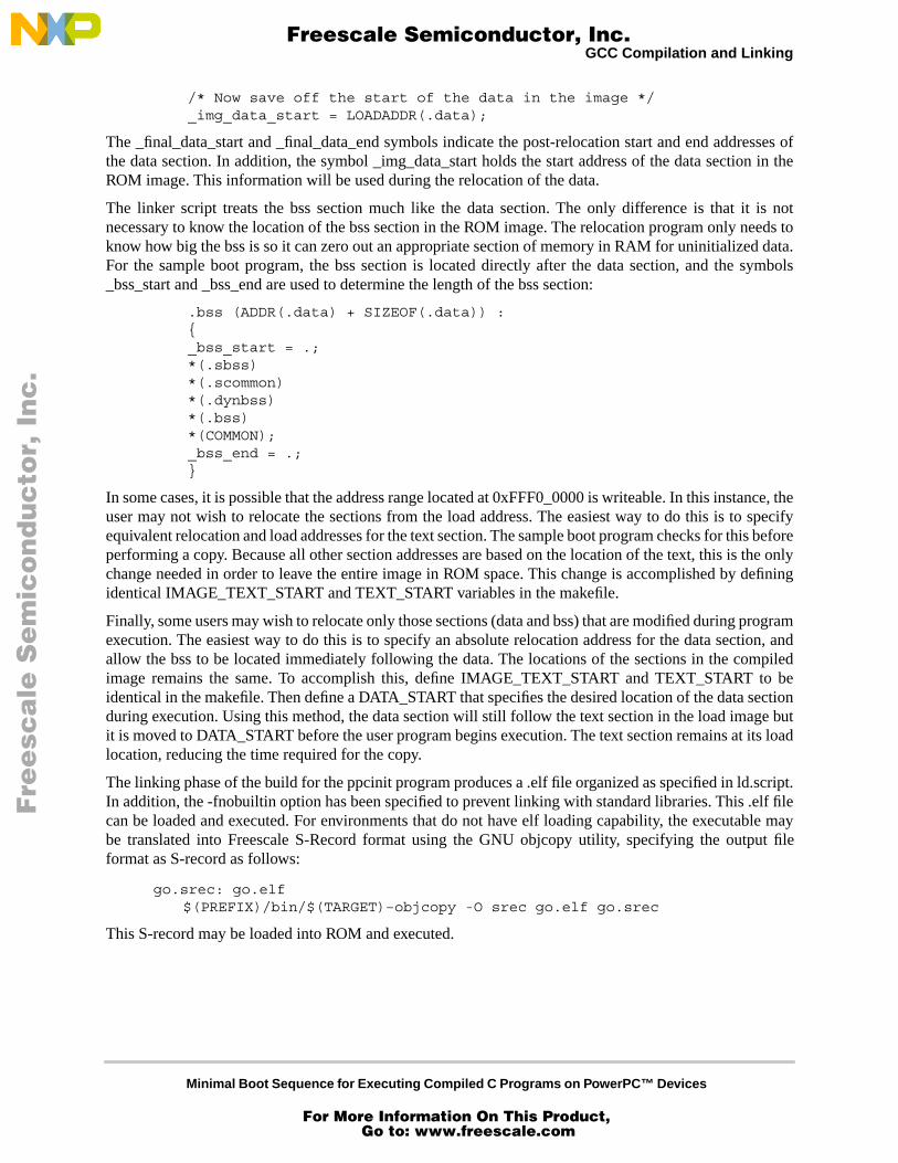
/* Now save off the start of the data in the image */_img_data_start = LOADADDR(.data);
The _final_data_start and _final_data_end symbols indicate the post-relocation start and end addresses ofthe data section. In addition, the symbol _img_data_start holds the start address of the data section in theROM image. This information will be used during the relocation of the data.
The linker script treats the bss section much like the data section. The only difference is that it is notnecessary to know the location of the bss section in the ROM image. The relocation program only needs toknow how big the bss is so it can zero out an appropriate section of memory in RAM for uninitialized data.For the sample boot program, the bss section is located directly after the data section, and the symbols_bss_start and _bss_end are used to determine the length of the bss section:
.bss (ADDR(.data) + SIZEOF(.data)) :{_bss_start = .;*(.sbss) *(.scommon)*(.dynbss)*(.bss)*(COMMON);_bss_end = .;}
In some cases, it is possible that the address range located at 0xFFF0_0000 is writeable. In this instance, theuser may not wish to relocate the sections from the load address. The easiest way to do this is to specifyequivalent relocation and load addresses for the text section. The sample boot program checks for this beforeperforming a copy. Because all other section addresses are based on the location of the text, this is the onlychange needed in order to leave the entire image in ROM space. This change is accomplished by definingidentical IMAGE_TEXT_START and TEXT_START variables in the makefile.
Finally, some users may wish to relocate only those sections (data and bss) that are modified during programexecution. The easiest way to do this is to specify an absolute relocation address for the data section, andallow the bss to be located immediately following the data. The locations of the sections in the compiledimage remains the same. To accomplish this, define IMAGE_TEXT_START and TEXT_START to beidentical in the makefile. Then define a DATA_START that specifies the desired location of the data sectionduring execution. Using this method, the data section will still follow the text section in the load image butit is moved to DATA_START before the user program begins execution. The text section remains at its loadlocation, reducing the time required for the copy.
The linking phase of the build for the ppcinit program produces a .elf file organized as specified in ld.script.In addition, the -fnobuiltin option has been specified to prevent linking with standard libraries. This .elf filecan be loaded and executed. For environments that do not have elf loading capability, the executable maybe translated into Freescale S-Record format using the GNU objcopy utility, specifying the output fileformat as S-record as follows:
go.srec: go.elf$(PREFIX)/bin/$(TARGET)–objcopy -O srec go.elf go.srec
This S-record may be loaded into ROM and executed.
Fre
esc
ale
Se
mic
on
du
cto
r, I
Freescale Semiconductor, Inc.
For More Information On This Product, Go to: www.freescale.com
nc
...
Minimal Boot Sequence for Executing Compiled C Programs on PowerPC™ Devices
Using the Sample Boot Sequence Using the Sample Boot Sequence
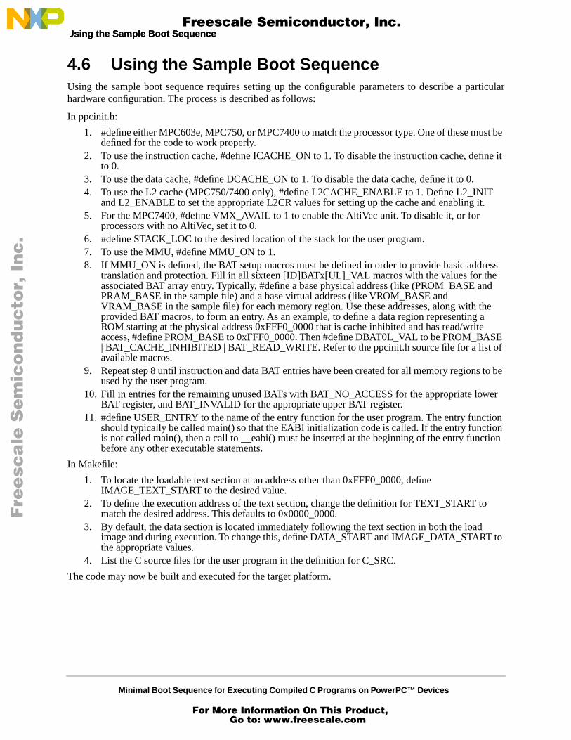
4.6 Using the Sample Boot Sequence
Using the sample boot sequence requires setting up the configurable parameters to describe a particularhardware configuration. The process is described as follows:
In ppcinit.h:
1. #define either MPC603e, MPC750, or MPC7400 to match the processor type. One of these must be defined for the code to work properly.
2. To use the instruction cache, #define ICACHE_ON to 1. To disable the instruction cache, define it to 0.
3. To use the data cache, #define DCACHE_ON to 1. To disable the data cache, define it to 0.4. To use the L2 cache (MPC750/7400 only), #define L2CACHE_ENABLE to 1. Define L2_INIT
and L2_ENABLE to set the appropriate L2CR values for setting up the cache and enabling it.5. For the MPC7400, #define VMX_AVAIL to 1 to enable the AltiVec unit. To disable it, or for
processors with no AltiVec, set it to 0.6. #define STACK_LOC to the desired location of the stack for the user program.7. To use the MMU, #define MMU_ON to 1. 8. If MMU_ON is defined, the BAT setup macros must be defined in order to provide basic address
translation and protection. Fill in all sixteen [ID]BATx[UL]_VAL macros with the values for the associated BAT array entry. Typically, #define a base physical address (like (PROM_BASE and PRAM_BASE in the sample file) and a base virtual address (like VROM_BASE and VRAM_BASE in the sample file) for each memory region. Use these addresses, along with the provided BAT macros, to form an entry. As an example, to define a data region representing a ROM starting at the physical address 0xFFF0_0000 that is cache inhibited and has read/write access, #define PROM_BASE to 0xFFF0_0000. Then #define DBAT0L_VAL to be PROM_BASE | BAT_CACHE_INHIBITED | BAT_READ_WRITE. Refer to the ppcinit.h source file for a list of available macros.
9. Repeat step 8 until instruction and data BAT entries have been created for all memory regions to be used by the user program.
10. Fill in entries for the remaining unused BATs with BAT_NO_ACCESS for the appropriate lower BAT register, and BAT_INVALID for the appropriate upper BAT register.
11. #define USER_ENTRY to the name of the entry function for the user program. The entry function should typically be called main() so that the EABI initialization code is called. If the entry function is not called main(), then a call to __eabi() must be inserted at the beginning of the entry function before any other executable statements.
In Makefile:
1. To locate the loadable text section at an address other than 0xFFF0_0000, define IMAGE_TEXT_START to the desired value.
2. To define the execution address of the text section, change the definition for TEXT_START to match the desired address. This defaults to 0x0000_0000.
3. By default, the data section is located immediately following the text section in both the load image and during execution. To change this, define DATA_START and IMAGE_DATA_START to the appropriate values.
4. List the C source files for the user program in the definition for C_SRC.
The code may now be built and executed for the target platform.
Fre
esc
ale
Se
mic
on
du
cto
r, I
Freescale Semiconductor, Inc.
For More Information On This Product, Go to: www.freescale.com
nc
...
Minimal Boot Sequence for Executing Compiled C Programs on PowerPC™ Devices
Limitations of the Sample Boot Sequence
4.7 Limitations of the Sample Boot SequenceThe sample boot sequence is intended to be used in a controlled environment and is designed to be asminimal as possible. As a result, there are some limitations to its design and use as follows:
1. The image should be built to be initially located at either 0xFFF0_0000 or 0x0000_0000.2. Memory is mapped via the BAT registers. The segment registers and page tables are not used.3. The segment registers, page table pointer, and page tables are not initialized. Care should be taken
to ensure that programs do not generate references to addresses in ranges not mapped by a BAT register. Doing so causes the processor to attempt to search the page table (whose location has not been defined and could point anywhere) for a translation. This could possibly result in reading/writing to random locations in memory.
4. No exception handling code is provided. With the exception of system reset, the exception vector locations contain the illegal opcode (0x0000_0000).
5. The code only initializes the processor; it does not initialize any peripheral devices and is not designed to be run in a system with a memory controller such as an Tundra Tsi106™ PowerPC host bridge. Additional code must be added to handle these situations.
6. Programs should avoid making stdio calls such as printf since there is no mechanism for handling these calls. The standard libraries are not linked with the user code since many of the functions in these libraries require specific platform support and therefore will not work when there is no OS running.
7. The sample sequence only performs setup necessary for standard C compiles. C++ programs and programs written in other languages may require additional support.
8. The sample boot sequence is designed to be minimal and to give the programmer as much control as possible. It does not use the standard __eabi() provided with the compiler. The standard __eabi() references symbols are not defined by the linking phase of the minimal boot and therefore will not link correctly.
9. The sample boot sequence has been tested with GNU compiler version 2.8.1 and the gnu linker version 2.9.1. It is possible and even likely that other versions will work as well.
10. The MPC7400 version of this code was designed to run on a model or chip revision at or greater than 2.9. Most production processors and models should be at or above this revision level. Previous chip revisions may require HID0, IABR, MSSCR0, and MSSCR1 to have special settings in order for some programs to run correctly. This application note does not provide source code to support these settings.
Part V Source FilesThe following sections contain the complete source code for the files ppcinit.S, ppcinit.h, ld.script, andmakefile.
5.1 ppcinit.S/*
// This file contains generic boot init code designed to be run on
// processor simulations that just need minimal setup.
//
// This code has also successfully been used to run processor-intensive
// benchmarks (written in C) from power-up on minimal hardware boards such as
// Excimer.
//
Fre
esc
ale
Se
mic
on
du
cto
r, I
Freescale Semiconductor, Inc.
For More Information On This Product, Go to: www.freescale.com
nc
...
Minimal Boot Sequence for Executing Compiled C Programs on PowerPC™ Devices
ppcinit.S ppcinit.S
// This code is designed to be run from Power-up or hard reset; running from
// soft reset may require additional operations such as cache invalidation,
// that are not supplied here.
//
// Once the hw init is complete, this code branches into the
// USER_ENTRY defined in the user code
//
// This code has been tested on the mpc603e, mpc750 and mpc7400/
// Architectural differences between processors with respect to cache
// types and sizes, cache management instructions, number of TLB
// entries, etc, may require changes to be made to this code before it may
// be used successfully on other processors.
//
// WARNING: If this code is run on a MAX! (MPC7400) processor
// earlier than rev 2.9, certain bits in HID0, IABR, MSSCR0, and
// MSSCR1 have to be set. Please refer to the processor errata if
// problems are encountered with this part.
*/
// NOTE: If you need to define variables, put them at the end! The _start
// symbol needs to be at hreset in order for this code to run automatically
// on hard reset.
#include "ppcinit.h"
.text
.global __eabi
.global _start
.space (0x0100) // locate at hreset vector
// this should now be located at the reset vector
_start:
b system_reset
.space (0x3000) // space past exception space
// here’s the real startup code, located outside the exception vector space
system_reset:
addis r0,0,0x0000
// from reset, the BATs are in an unknown state on most PPCs.
// Invalidate them all to avoid error states
mtspr ibat0u,r0
mtspr ibat1u,r0
mtspr ibat2u,r0
Fre
esc
ale
Se
mic
on
du
cto
r, I
Freescale Semiconductor, Inc.
For More Information On This Product, Go to: www.freescale.com
nc
...
Minimal Boot Sequence for Executing Compiled C Programs on PowerPC™ Devices
ppcinit.S
mtspr ibat3u,r0
isync
mtspr dbat0u,r0
mtspr dbat1u,r0
mtspr dbat2u,r0
mtspr dbat3u,r0
isync
// If there’s L2 cache we enable later, set it up and invalidate it.
// Don’t turn it on until after the ROM-RAM copy of the image so
// we don’t preload the caches (in case we’re going to run a benchmark).
#if L2CACHE_ENABLE == 1
addis r3,r0,L2_INIT@h
ori r3,r3,L2_INIT@l
mtspr l2cr,r3
// This invalidate serves two purposes.
// First, it invalidates the L2 cache.
// Second, it ensures that when this section of code has completed
// execution, the L2 DLL will have stabilized.
L2_invalidate:
#if defined(MPC7400) && defined(VMX_AVAIL)
.long 0x7e00066c // dssall instruction, not all compilers
// understand it yet. Actually, as
// long as this code is run from hard
// reset, before any data stream touch
// instructions, this instruction isn’t needed.
// I’m putting in for correctness in case
// someone cut-and-pastes this code into
// another application.
#endif
sync
oris r3, r3, 0x0020
mtspr l2cr, r3
sync
invalidate:
mfspr r3, l2cr
andi. r3, r3, 0x1
bne invalidate
// turn off the L2I global invalidate bit
mfspr r3, l2cr
Fre
esc
ale
Se
mic
on
du
cto
r, I
Freescale Semiconductor, Inc.
For More Information On This Product, Go to: www.freescale.com
nc
...
Minimal Boot Sequence for Executing Compiled C Programs on PowerPC™ Devices
ppcinit.S ppcinit.S
rlwinm r3,r3,0,11,9
mtspr l2cr, r3
#endif // L2CACHE_ENABLE
// Note MSR state at power-up:
// all exceptions disabled, address translation off,
// Exception prefix at 0xfff00000, FP disabled
#if MMU_ON == 1
// If the code specifies that we’re going to use the MMU, branch to
// to the setup function that handles setting up the BATs and
// invalidating TLB entries.
//
// NOTE: We’ve done nothing with the segment registers, so we need to
// be sure that all memory accessed by this code and by the user
// program is represented in the BATs. Otherwise, we might get
// some spurious translations.
bl setup_bats
sync
bl address_translation_on
sync
#endif
// relocate the text, data, and bss segments
bl relocate_image
// Note: This code is run from reset, so we assume that there is no
// data that needs to be flushed from the cache. This code only
// invalidates and enables the caches, it does not flush!
//
// Note: The caches are enabled *after* the relocation in order
// to help avoid cache preloading.
#if DCACHE_ON == 1
bl invalidate_and_enable_L1_dcache
#endif
#if ICACHE_ON == 1
bl invalidate_and_enable_L1_icache
#endif
Fre
esc
ale
Se
mic
on
du
cto
r, I
Freescale Semiconductor, Inc.
For More Information On This Product, Go to: www.freescale.com
nc
...
Minimal Boot Sequence for Executing Compiled C Programs on PowerPC™ Devices
ppcinit.S
#if L2CACHE_ENABLE == 1
addis r3,r0,L2_ENABLE@h
ori r3,r3,L2_ENABLE@l
mtspr l2cr,r3
#endif
// get the start address of the main routine of the code we want to run.
addis r3,r0,USER_ENTRY@h
ori r3,r3,USER_ENTRY@l
mtspr srr0,r3
// Set the MSR.
// we just move the value into srr1 - it will get copied into
// the msr upon the rfi.
#if VMX_AVAIL == 1
addis r4,0,0x0200
#else
addis r4,0,0x0000
#endif
ori r4,r4,0x3900 // turn on fp,
// enable fp & machine check exceptions
#if MMU_ON == 1
ori r4,r4,0x0030 // turn on I and D translation
#endif
// See if we relocated the code to an address above 0xffc00000.
// If so, put the exception prefix at 0xfff00000. Otherwise,
// make it at 0.
addis r5,0,0xffc0
ori r5,r5,0x0000
cmp 0,0,r5,r3
blt set_state
ori r4,r4,0x0040 // put exception prefix at 0xfff00000
// in our new msr
set_state:
// Put r4 into srr1 so it gets copied into the msr on rfi
mtspr srr1,r4
// let’s put something in the link register - when the user program
// starts, it’s going to save the link register, do it’s thing, then
// restore the link register and blr.
Fre
esc
ale
Se
mic
on
du
cto
r, I
Freescale Semiconductor, Inc.
For More Information On This Product, Go to: www.freescale.com
nc
...
Minimal Boot Sequence for Executing Compiled C Programs on PowerPC™ Devices
ppcinit.S ppcinit.S
// we’ll put in the address following the rfi so we can save
// off the time base once the user code is complete
addis r3,0,save_timebase@h
ori r3,r3,save_timebase@l
mtlr r3
// set up the time base register
addis r4,r0,0x0000
mtspr 285,r4
mtspr 284,r4
// Set up stack pointer for the user application
addis r1,r0,STACK_LOC@h // STACK_LOC defined in ppcinit.h
ori r1,r1,STACK_LOC@l
// make sure the word the stack pointer points to is NULL
addis r14,r0,0x0000
stw r14,0(r1)
// go to the C code
rfi
save_timebase:
// read time base, checking for rollover
mfspr r3,269
mfspr r4,268
mfspr r5,269
cmpw r5,r3
bne save_timebase
// save vals off
addis r5,0,TBUSAVE@h
ori r5,r5,TBUSAVE@l
stw r3,0(r5)
addis r5,0,TBLSAVE@h
ori r5,r5,TBLSAVE@l
stw r4,0(r5)
// done, go to an arbitrary address
done:
addis r3,0,0xfff0
ori r3,r3,0x0700
mtlr r3
Fre
esc
ale
Se
mic
on
du
cto
r, I
Freescale Semiconductor, Inc.
For More Information On This Product, Go to: www.freescale.com
nc
...
Minimal Boot Sequence for Executing Compiled C Programs on PowerPC™ Devices
ppcinit.S
blr
//
// Label: __eabi()
//
// Replaces standard __eabi(). This is a minimal __eabi, because we don’t
// require anything to happen here other than setting up the SDA pointers.
//
__eabi:
// Get small data area locations as per PPC EABI // See http://freescale.com/semiconductors (search on EABI)
// for more information.
addis r13,r0,_SDA_BASE_@h
ori r13,r13,_SDA_BASE_@l
addis r2,r0,_SDA2_BASE_@h
ori r2,r2,_SDA2_BASE_@l
blr
//---------------------------------------------------------------------------
// Label: relocate_image
//
// copy this image and the user code into RAM space.
// Note that the starting locations of text, data, and bss are
// defined in the ld.script. Make sure these definitions,
// as well as the definition for STACK_LOC in ppcinit.h, give
// ample room for your image.
//---------------------------------------------------------------------------
relocate_image:
addis r3,0,_img_text_start@h
ori r3,r3,_img_text_start@l
addis r4,0,_final_text_start@h
ori r4,r4,_final_text_start@l
// are they the same? No need to relocate if so
cmp 0,0,r3,r4
beq relocate_data
addis r7,0,_img_text_end@h
ori r7,r7,_img_text_end@l
cont:
Fre
esc
ale
Se
mic
on
du
cto
r, I
Freescale Semiconductor, Inc.
For More Information On This Product, Go to: www.freescale.com
nc
...
Minimal Boot Sequence for Executing Compiled C Programs on PowerPC™ Devices
ppcinit.S ppcinit.S
lwzx r5,0,r3
stwx r5,0,r4
lwzx r8,0,r4
cmp 0,0,r8,r5
bne error
addi r4,r4,4
addi r3,r3,4
cmp 0,0,r3,r7
ble cont
relocate_data:
addis r3,0,_final_data_start@h
ori r3,r3,_final_data_start@l
addis r7,0,_final_data_end@h
ori r7,r7,_final_data_end@l
addis r4,0,_img_data_start@h
ori r4,r4,_img_data_start@l
cmp 0,0,r3,r4 // is the data not relocated?
beq clear_bss // if not, go do the bss
cont1:
lwzx r5,0,r4
stwx r5,0,r3
lwzx r8,0,r3
cmp 0,0,r8,r5
bne error
addi r4,r4,4
addi r3,r3,4
cmp 0,0,r3,r7
ble cont1
// This clear_bss code can be removed if you’re sure you never
// depend on uninitialized data being 0.
clear_bss:
addis r4,0,_bss_start@h
ori r4,r4,_bss_start@l
Fre
esc
ale
Se
mic
on
du
cto
r, I
Freescale Semiconductor, Inc.
For More Information On This Product, Go to: www.freescale.com
nc
...
Minimal Boot Sequence for Executing Compiled C Programs on PowerPC™ Devices
ppcinit.S
addis r7,0,_bss_end@h
ori r7,r7,_bss_end@l
addis r5,0,0x0000
cont2:
stwx r5,0,r4
addi r4,r4,4
cmp 0,0,r4,r7
ble cont2
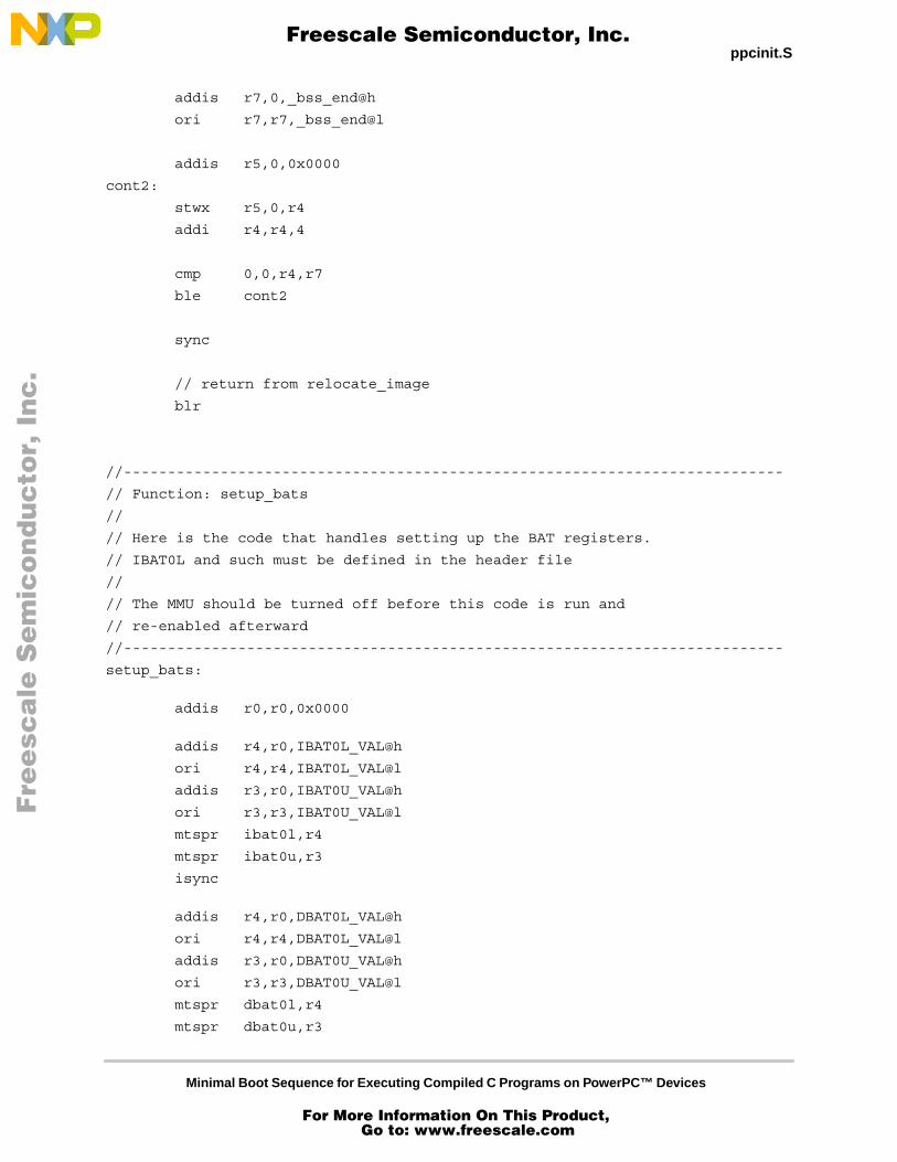
sync
// return from relocate_image
blr
//---------------------------------------------------------------------------
// Function: setup_bats
//
// Here is the code that handles setting up the BAT registers.
// IBAT0L and such must be defined in the header file
//
// The MMU should be turned off before this code is run and
// re-enabled afterward
//---------------------------------------------------------------------------
setup_bats:
addis r0,r0,0x0000
addis r4,r0,IBAT0L_VAL@h
ori r4,r4,IBAT0L_VAL@l
addis r3,r0,IBAT0U_VAL@h
ori r3,r3,IBAT0U_VAL@l
mtspr ibat0l,r4
mtspr ibat0u,r3
isync
addis r4,r0,DBAT0L_VAL@h
ori r4,r4,DBAT0L_VAL@l
addis r3,r0,DBAT0U_VAL@h
ori r3,r3,DBAT0U_VAL@l
mtspr dbat0l,r4
mtspr dbat0u,r3
Fre
esc
ale
Se
mic
on
du
cto
r, I
Freescale Semiconductor, Inc.
For More Information On This Product, Go to: www.freescale.com
nc
...
Minimal Boot Sequence for Executing Compiled C Programs on PowerPC™ Devices
ppcinit.S ppcinit.S
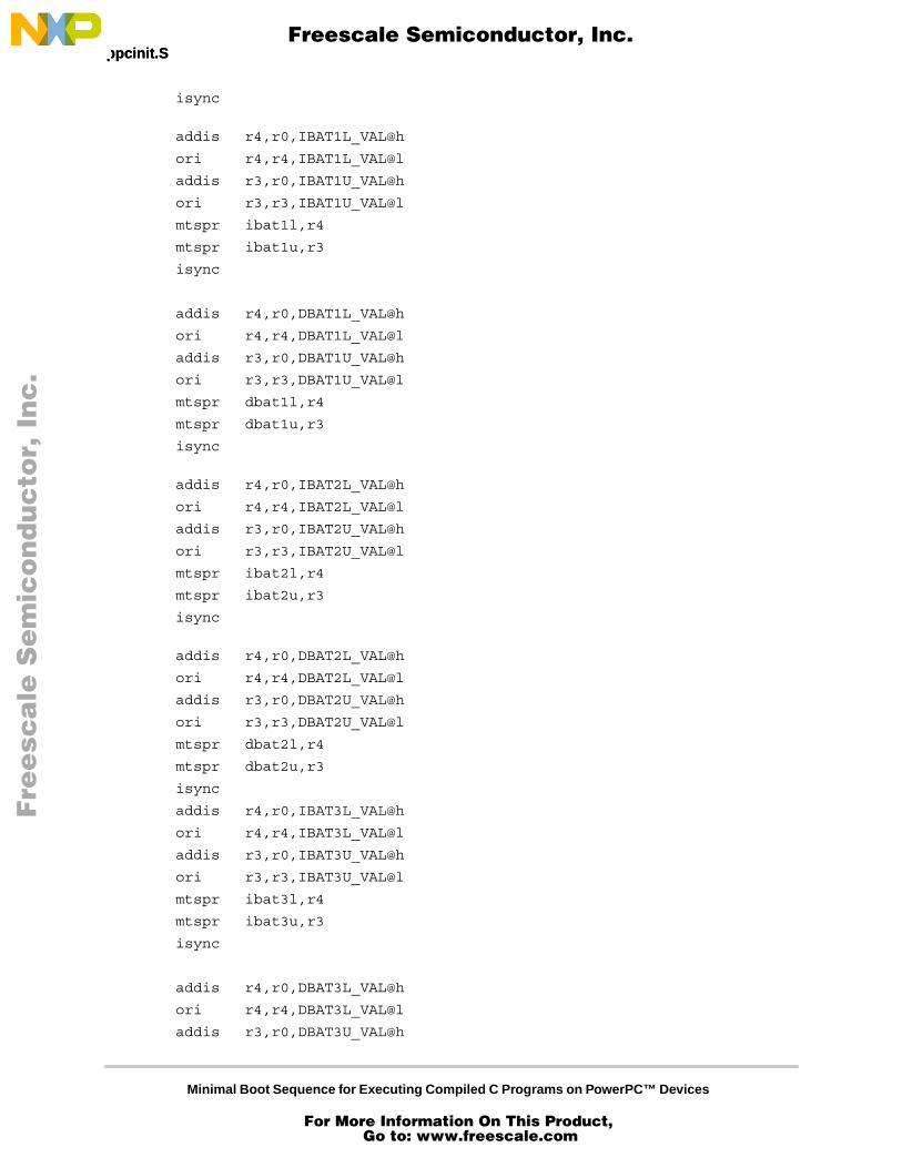
isync
addis r4,r0,IBAT1L_VAL@h
ori r4,r4,IBAT1L_VAL@l
addis r3,r0,IBAT1U_VAL@h
ori r3,r3,IBAT1U_VAL@l
mtspr ibat1l,r4
mtspr ibat1u,r3
isync
addis r4,r0,DBAT1L_VAL@h
ori r4,r4,DBAT1L_VAL@l
addis r3,r0,DBAT1U_VAL@h
ori r3,r3,DBAT1U_VAL@l
mtspr dbat1l,r4
mtspr dbat1u,r3
isync
addis r4,r0,IBAT2L_VAL@h
ori r4,r4,IBAT2L_VAL@l
addis r3,r0,IBAT2U_VAL@h
ori r3,r3,IBAT2U_VAL@l
mtspr ibat2l,r4
mtspr ibat2u,r3
isync
addis r4,r0,DBAT2L_VAL@h
ori r4,r4,DBAT2L_VAL@l
addis r3,r0,DBAT2U_VAL@h
ori r3,r3,DBAT2U_VAL@l
mtspr dbat2l,r4
mtspr dbat2u,r3
isync
addis r4,r0,IBAT3L_VAL@h
ori r4,r4,IBAT3L_VAL@l
addis r3,r0,IBAT3U_VAL@h
ori r3,r3,IBAT3U_VAL@l
mtspr ibat3l,r4
mtspr ibat3u,r3
isync
addis r4,r0,DBAT3L_VAL@h
ori r4,r4,DBAT3L_VAL@l
addis r3,r0,DBAT3U_VAL@h
Fre
esc
ale
Se
mic
on
du
cto
r, I
Freescale Semiconductor, Inc.
For More Information On This Product, Go to: www.freescale.com
nc
...
Minimal Boot Sequence for Executing Compiled C Programs on PowerPC™ Devices
ppcinit.S
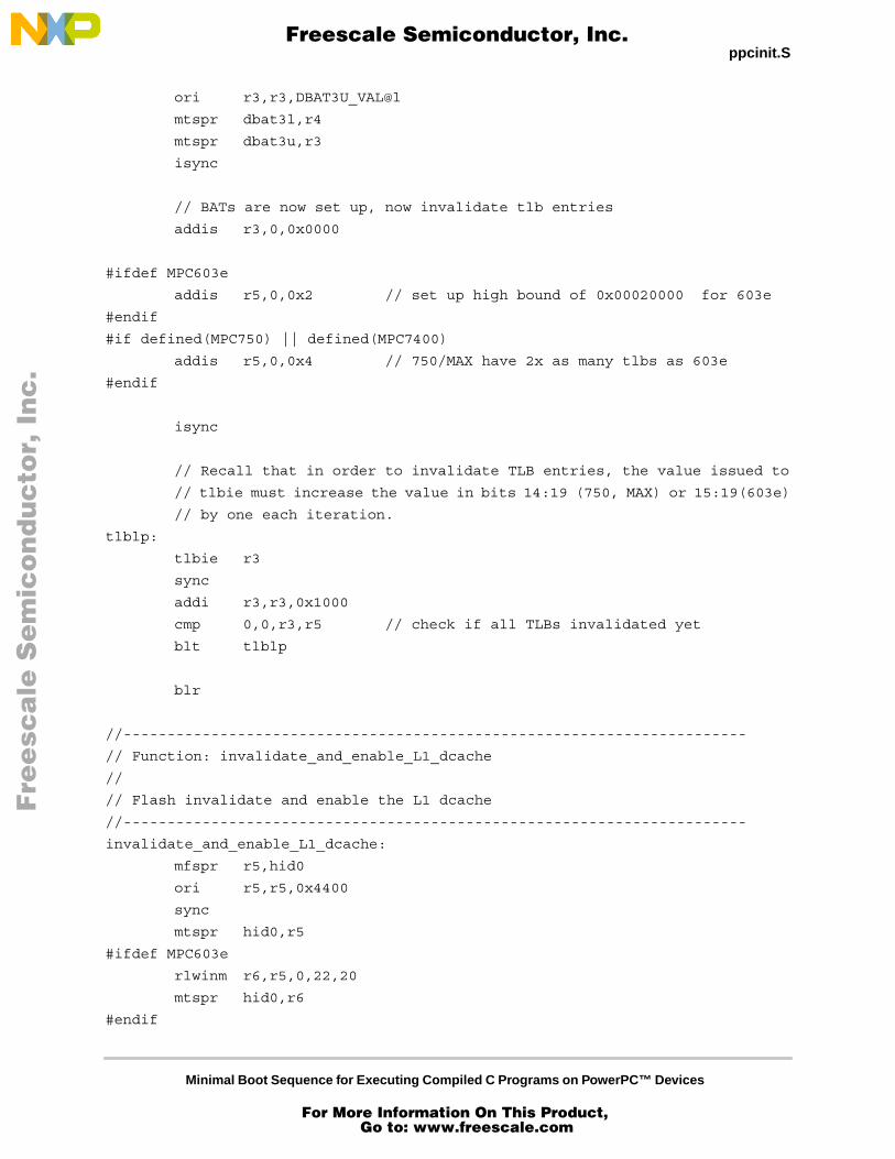
ori r3,r3,DBAT3U_VAL@l
mtspr dbat3l,r4
mtspr dbat3u,r3
isync
// BATs are now set up, now invalidate tlb entries
addis r3,0,0x0000
#ifdef MPC603e
addis r5,0,0x2 // set up high bound of 0x00020000 for 603e
#endif
#if defined(MPC750) || defined(MPC7400)
addis r5,0,0x4 // 750/MAX have 2x as many tlbs as 603e
#endif
isync
// Recall that in order to invalidate TLB entries, the value issued to
// tlbie must increase the value in bits 14:19 (750, MAX) or 15:19(603e)
// by one each iteration.
tlblp:
tlbie r3
sync
addi r3,r3,0x1000
cmp 0,0,r3,r5 // check if all TLBs invalidated yet
blt tlblp
blr
//-----------------------------------------------------------------------
// Function: invalidate_and_enable_L1_dcache
//
// Flash invalidate and enable the L1 dcache
//-----------------------------------------------------------------------
invalidate_and_enable_L1_dcache:
mfspr r5,hid0
ori r5,r5,0x4400
sync
mtspr hid0,r5
#ifdef MPC603e
rlwinm r6,r5,0,22,20
mtspr hid0,r6
#endif
Fre
esc
ale
Se
mic
on
du
cto
r, I
Freescale Semiconductor, Inc.
For More Information On This Product, Go to: www.freescale.com
nc
...
Minimal Boot Sequence for Executing Compiled C Programs on PowerPC™ Devices
ppcinit.S ppcinit.S
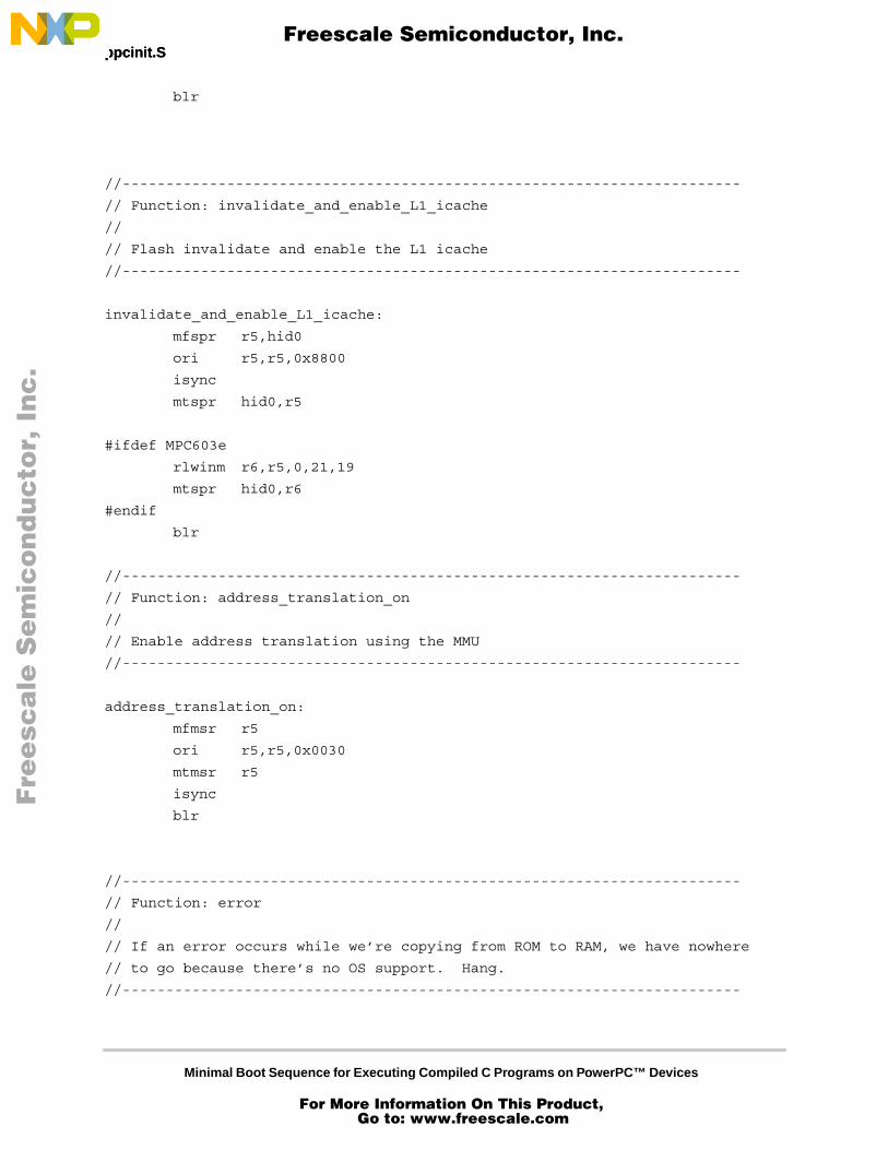
blr
//-----------------------------------------------------------------------
// Function: invalidate_and_enable_L1_icache
//
// Flash invalidate and enable the L1 icache
//-----------------------------------------------------------------------
invalidate_and_enable_L1_icache:
mfspr r5,hid0
ori r5,r5,0x8800
isync
mtspr hid0,r5
#ifdef MPC603e
rlwinm r6,r5,0,21,19
mtspr hid0,r6
#endif
blr
//-----------------------------------------------------------------------
// Function: address_translation_on
//
// Enable address translation using the MMU
//-----------------------------------------------------------------------
address_translation_on:
mfmsr r5
ori r5,r5,0x0030
mtmsr r5
isync
blr
//-----------------------------------------------------------------------
// Function: error
//
// If an error occurs while we’re copying from ROM to RAM, we have nowhere
// to go because there’s no OS support. Hang.
//-----------------------------------------------------------------------
Fre
esc
ale
Se
mic
on
du
cto
r, I
Freescale Semiconductor, Inc.
For More Information On This Product, Go to: www.freescale.com
nc
...
Minimal Boot Sequence for Executing Compiled C Programs on PowerPC™ Devices
ppcinit.h
error:
b error
//---------------------------------------------------------------------
//
// Define space for data items needed by this code
//
//---------------------------------------------------------------------
.data
/* save time base to use for benchmarking numbers */
TBUSAVE:
.double 0
TBLSAVE:
.double 0
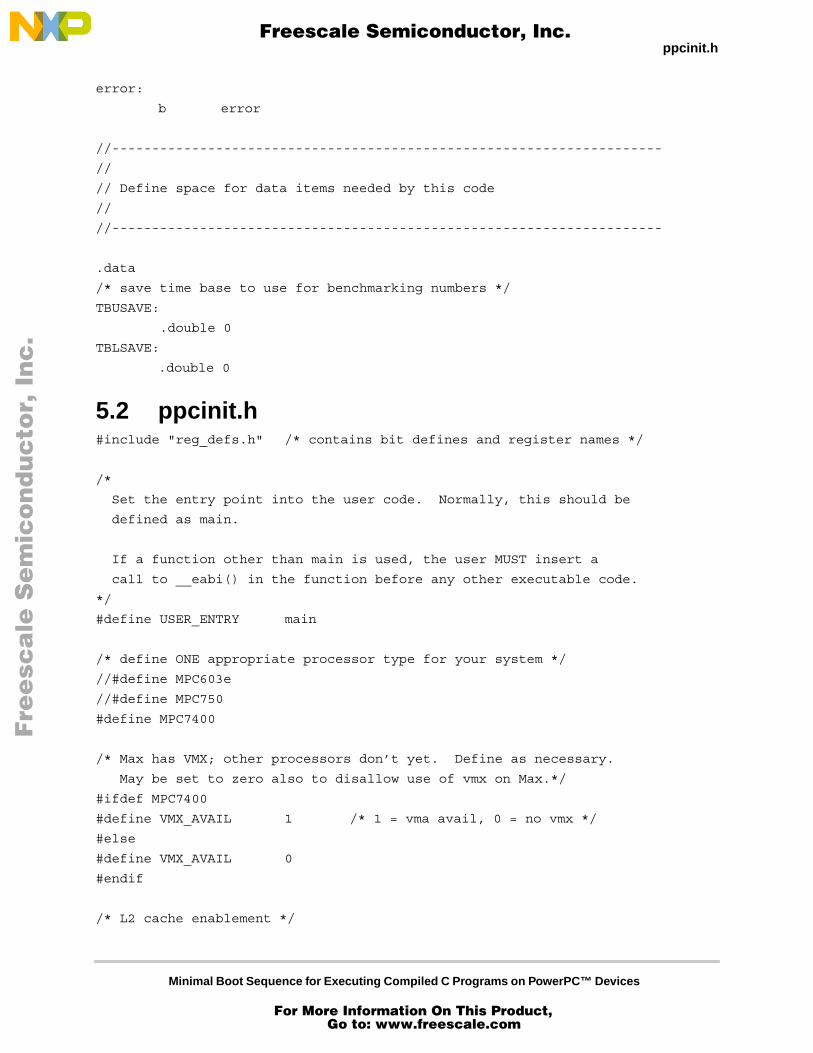
5.2 ppcinit.h#include "reg_defs.h" /* contains bit defines and register names */
/*
Set the entry point into the user code. Normally, this should be
defined as main.
If a function other than main is used, the user MUST insert a
call to __eabi() in the function before any other executable code.
*/
#define USER_ENTRY main
/* define ONE appropriate processor type for your system */
//#define MPC603e
//#define MPC750
#define MPC7400
/* Max has VMX; other processors don’t yet. Define as necessary.
May be set to zero also to disallow use of vmx on Max.*/
#ifdef MPC7400
#define VMX_AVAIL 1 /* 1 = vma avail, 0 = no vmx */
#else
#define VMX_AVAIL 0
#endif
/* L2 cache enablement */
Fre
esc
ale
Se
mic
on
du
cto
r, I
Freescale Semiconductor, Inc.
For More Information On This Product, Go to: www.freescale.com
nc
...

Minimal Boot Sequence for Executing Compiled C Programs on PowerPC™ Devices
ppcinit.h ppcinit.h
#ifdef MPC603e
#define L2CACHE_ENABLE 0 /* just note that there’s no L2 on 603e */
#else /* 750 or 7400 */
#define L2CACHE_ENABLE 1 /* default - L2 on for Max and Arthur */
/*
* L2_INIT is used to set up the L2 cache as follows:
* size = .5 MB
* clock ratio = div 2
* RAM type = burst SRAM
* Output Hold = 0.5ns
*
* These may need to be changed for your board. Refer to your board specs and your
* processor manual for more information on setting up the L2 cache
*/
#define L2_INIT (L2CR_L2SIZ_HM|L2CR_L2CLK_2|L2CR_L2RAM_BURST| L2CR_L2OH_5)
#define L2_ENABLE (L2_INIT | L2CR_L2E)
#endif
/* L1 Instruction and data caches on or off? */
#define ICACHE_ON 1
#define DCACHE_ON 1
/* Where should I put the stack? Upper and lower address bits
This number should be 16-byte aligned (PPC ABI) or 8-byte aligned (PPC EABI)
*/
#define STACK_LOC 0x00070000
/* Do we want to use the MMU’s address translation ability? */
#define MMU_ON 1
/*
If we’re using the MMU we need to set up the BAT registers.
Since we don’t have a nice operating system handling page
table entries and the like for us, the BATs provide the
easiest translation mechanism.
The User must define the bat mappings here. For unused BATs, specify the
BAT as INVALID and having NO_ACCESS as shown for bats 2 and 3 below.
This code maps everything, including the ROM and instruction space as
read-write because we’re in a simulator and might want to do something
Fre
esc
ale
Se
mic
on
du
cto
r, I
Freescale Semiconductor, Inc.
For More Information On This Product, Go to: www.freescale.com
nc
...
Minimal Boot Sequence for Executing Compiled C Programs on PowerPC™ Devices
reg_defs.h
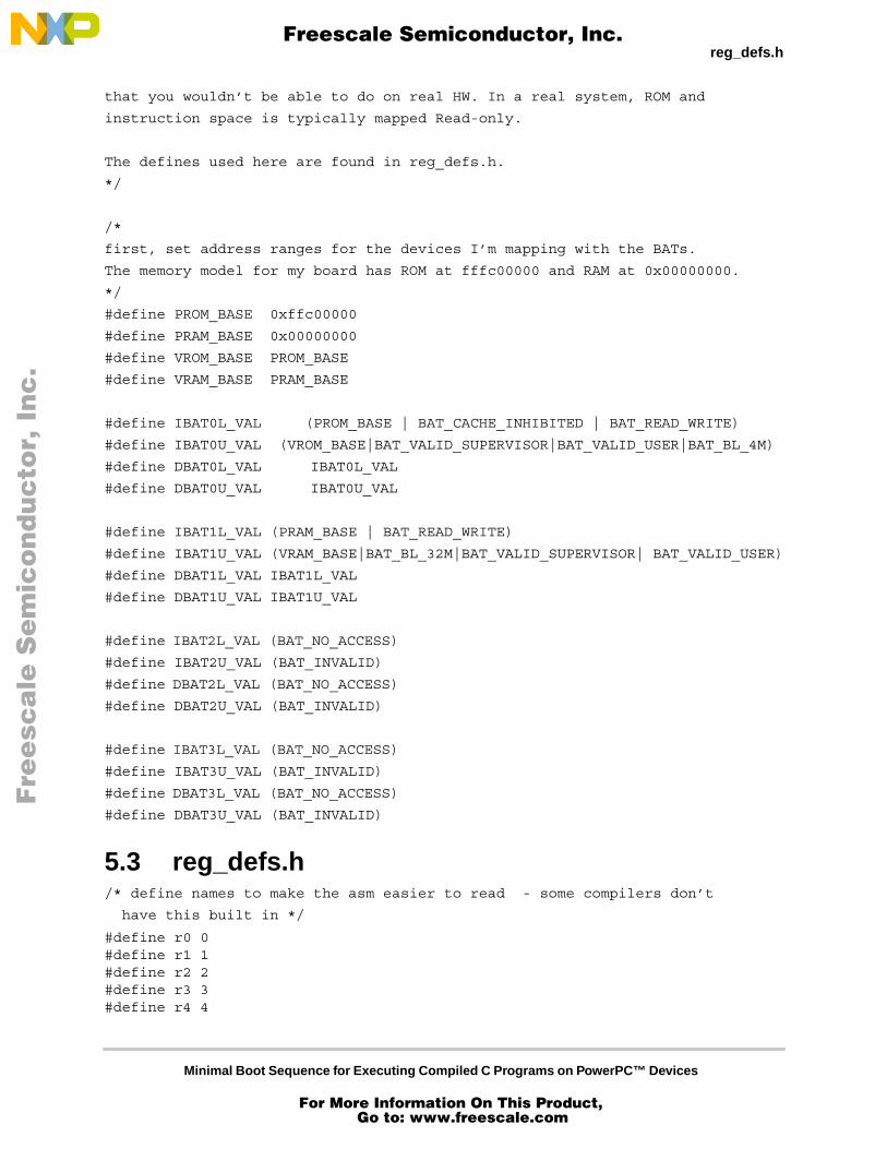
that you wouldn’t be able to do on real HW. In a real system, ROM and
instruction space is typically mapped Read-only.
The defines used here are found in reg_defs.h.
*/
/*
first, set address ranges for the devices I’m mapping with the BATs.
The memory model for my board has ROM at fffc00000 and RAM at 0x00000000.
*/
#define PROM_BASE 0xffc00000
#define PRAM_BASE 0x00000000
#define VROM_BASE PROM_BASE
#define VRAM_BASE PRAM_BASE
#define IBAT0L_VAL (PROM_BASE | BAT_CACHE_INHIBITED | BAT_READ_WRITE)
#define IBAT0U_VAL (VROM_BASE|BAT_VALID_SUPERVISOR|BAT_VALID_USER|BAT_BL_4M)
#define DBAT0L_VAL IBAT0L_VAL
#define DBAT0U_VAL IBAT0U_VAL
#define IBAT1L_VAL (PRAM_BASE | BAT_READ_WRITE)
#define IBAT1U_VAL (VRAM_BASE|BAT_BL_32M|BAT_VALID_SUPERVISOR| BAT_VALID_USER)
#define DBAT1L_VAL IBAT1L_VAL
#define DBAT1U_VAL IBAT1U_VAL
#define IBAT2L_VAL (BAT_NO_ACCESS)
#define IBAT2U_VAL (BAT_INVALID)
#define DBAT2L_VAL (BAT_NO_ACCESS)
#define DBAT2U_VAL (BAT_INVALID)
#define IBAT3L_VAL (BAT_NO_ACCESS)
#define IBAT3U_VAL (BAT_INVALID)
#define DBAT3L_VAL (BAT_NO_ACCESS)
#define DBAT3U_VAL (BAT_INVALID)
5.3 reg_defs.h/* define names to make the asm easier to read - some compilers don’t
have this built in */
#define r0 0#define r1 1#define r2 2#define r3 3#define r4 4
Fre
esc
ale
Se
mic
on
du
cto
r, I
Freescale Semiconductor, Inc.
For More Information On This Product, Go to: www.freescale.com
nc
...
Minimal Boot Sequence for Executing Compiled C Programs on PowerPC™ Devices
reg_defs.h reg_defs.h
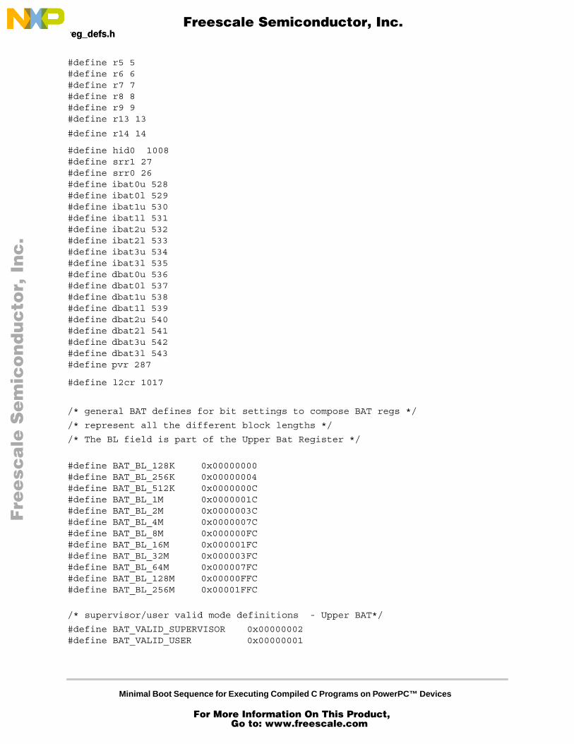
#define r5 5#define r6 6#define r7 7#define r8 8#define r9 9#define r13 13
#define r14 14
#define hid0 1008#define srr1 27#define srr0 26#define ibat0u 528#define ibat0l 529#define ibat1u 530#define ibat1l 531#define ibat2u 532#define ibat2l 533#define ibat3u 534#define ibat3l 535#define dbat0u 536#define dbat0l 537#define dbat1u 538#define dbat1l 539#define dbat2u 540#define dbat2l 541#define dbat3u 542#define dbat3l 543#define pvr 287
#define l2cr 1017
/* general BAT defines for bit settings to compose BAT regs */
/* represent all the different block lengths */
/* The BL field is part of the Upper Bat Register */
#define BAT_BL_128K 0x00000000#define BAT_BL_256K 0x00000004#define BAT_BL_512K 0x0000000C#define BAT_BL_1M 0x0000001C#define BAT_BL_2M 0x0000003C#define BAT_BL_4M 0x0000007C#define BAT_BL_8M 0x000000FC#define BAT_BL_16M 0x000001FC#define BAT_BL_32M 0x000003FC#define BAT_BL_64M 0x000007FC#define BAT_BL_128M 0x00000FFC#define BAT_BL_256M 0x00001FFC
/* supervisor/user valid mode definitions - Upper BAT*/
#define BAT_VALID_SUPERVISOR 0x00000002#define BAT_VALID_USER 0x00000001
Fre
esc
ale
Se
mic
on
du
cto
r, I
Freescale Semiconductor, Inc.
For More Information On This Product, Go to: www.freescale.com
nc
...
Minimal Boot Sequence for Executing Compiled C Programs on PowerPC™ Devices
ld.script
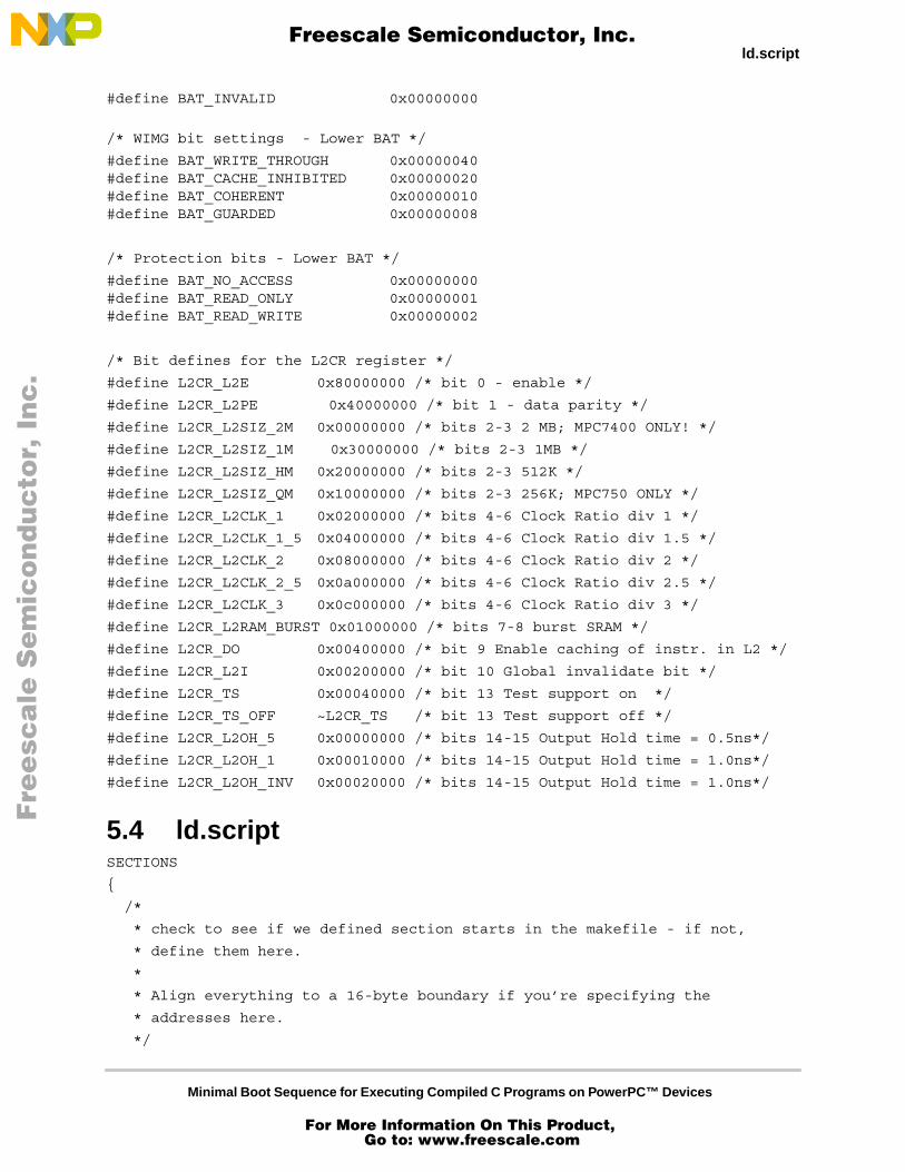
#define BAT_INVALID 0x00000000
/* WIMG bit settings - Lower BAT */
#define BAT_WRITE_THROUGH 0x00000040#define BAT_CACHE_INHIBITED 0x00000020#define BAT_COHERENT 0x00000010#define BAT_GUARDED 0x00000008
/* Protection bits - Lower BAT */
#define BAT_NO_ACCESS 0x00000000#define BAT_READ_ONLY 0x00000001#define BAT_READ_WRITE 0x00000002
/* Bit defines for the L2CR register */
#define L2CR_L2E 0x80000000 /* bit 0 - enable */
#define L2CR_L2PE 0x40000000 /* bit 1 - data parity */
#define L2CR_L2SIZ_2M 0x00000000 /* bits 2-3 2 MB; MPC7400 ONLY! */
#define L2CR_L2SIZ_1M 0x30000000 /* bits 2-3 1MB */
#define L2CR_L2SIZ_HM 0x20000000 /* bits 2-3 512K */
#define L2CR_L2SIZ_QM 0x10000000 /* bits 2-3 256K; MPC750 ONLY */
#define L2CR_L2CLK_1 0x02000000 /* bits 4-6 Clock Ratio div 1 */
#define L2CR_L2CLK_1_5 0x04000000 /* bits 4-6 Clock Ratio div 1.5 */
#define L2CR_L2CLK_2 0x08000000 /* bits 4-6 Clock Ratio div 2 */
#define L2CR_L2CLK_2_5 0x0a000000 /* bits 4-6 Clock Ratio div 2.5 */
#define L2CR_L2CLK_3 0x0c000000 /* bits 4-6 Clock Ratio div 3 */
#define L2CR_L2RAM_BURST 0x01000000 /* bits 7-8 burst SRAM */
#define L2CR_DO 0x00400000 /* bit 9 Enable caching of instr. in L2 */
#define L2CR_L2I 0x00200000 /* bit 10 Global invalidate bit */
#define L2CR_TS 0x00040000 /* bit 13 Test support on */
#define L2CR_TS_OFF ~L2CR_TS /* bit 13 Test support off */
#define L2CR_L2OH_5 0x00000000 /* bits 14-15 Output Hold time = 0.5ns*/
#define L2CR_L2OH_1 0x00010000 /* bits 14-15 Output Hold time = 1.0ns*/
#define L2CR_L2OH_INV 0x00020000 /* bits 14-15 Output Hold time = 1.0ns*/
5.4 ld.scriptSECTIONS
{
/*
* check to see if we defined section starts in the makefile - if not,
* define them here.
*
* Align everything to a 16-byte boundary if you’re specifying the
* addresses here.
*/
Fre
esc
ale
Se
mic
on
du
cto
r, I
Freescale Semiconductor, Inc.
For More Information On This Product, Go to: www.freescale.com
nc
...
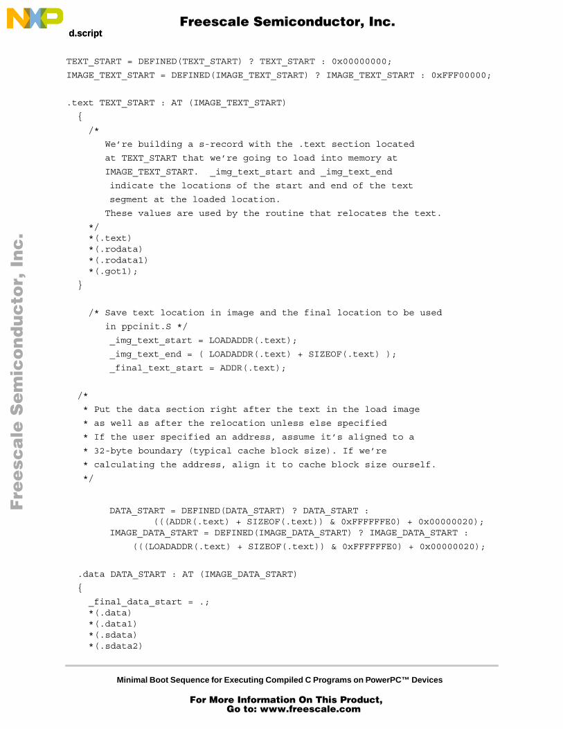
Minimal Boot Sequence for Executing Compiled C Programs on PowerPC™ Devices
ld.script ld.script
TEXT_START = DEFINED(TEXT_START) ? TEXT_START : 0x00000000;
IMAGE_TEXT_START = DEFINED(IMAGE_TEXT_START) ? IMAGE_TEXT_START : 0xFFF00000;
.text TEXT_START : AT (IMAGE_TEXT_START)
{
/*
We’re building a s-record with the .text section located
at TEXT_START that we’re going to load into memory at
IMAGE_TEXT_START. _img_text_start and _img_text_end
indicate the locations of the start and end of the text
segment at the loaded location.
These values are used by the routine that relocates the text.
*/ *(.text) *(.rodata) *(.rodata1) *(.got1);
}
/* Save text location in image and the final location to be used
in ppcinit.S */
_img_text_start = LOADADDR(.text);
_img_text_end = ( LOADADDR(.text) + SIZEOF(.text) );
_final_text_start = ADDR(.text);
/*
* Put the data section right after the text in the load image
* as well as after the relocation unless else specified
* If the user specified an address, assume it’s aligned to a
* 32-byte boundary (typical cache block size). If we’re
* calculating the address, align it to cache block size ourself.
*/
DATA_START = DEFINED(DATA_START) ? DATA_START : (((ADDR(.text) + SIZEOF(.text)) & 0xFFFFFFE0) + 0x00000020);
IMAGE_DATA_START = DEFINED(IMAGE_DATA_START) ? IMAGE_DATA_START :
(((LOADADDR(.text) + SIZEOF(.text)) & 0xFFFFFFE0) + 0x00000020);
.data DATA_START : AT (IMAGE_DATA_START)
{
_final_data_start = .; *(.data) *(.data1) *(.sdata) *(.sdata2)
Fre
esc
ale
Se
mic
on
du
cto
r, I
Freescale Semiconductor, Inc.
For More Information On This Product, Go to: www.freescale.com
nc
...
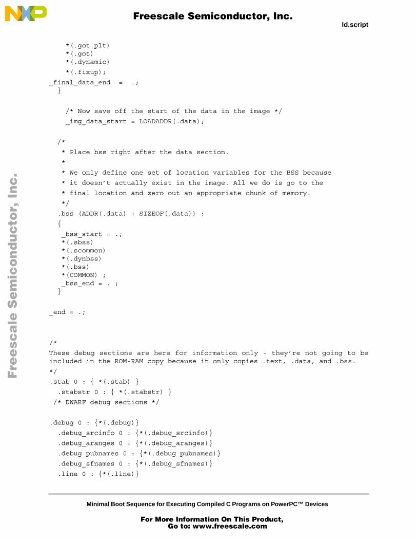
Minimal Boot Sequence for Executing Compiled C Programs on PowerPC™ Devices
ld.script
*(.got.plt) *(.got) *(.dynamic)
*(.fixup);
_final_data_end = .; }
/* Now save off the start of the data in the image */
_img_data_start = LOADADDR(.data);
/*
* Place bss right after the data section.
*
* We only define one set of location variables for the BSS because
* it doesn’t actually exist in the image. All we do is go to the
* final location and zero out an appropriate chunk of memory.
*/
.bss (ADDR(.data) + SIZEOF(.data)) :
{
_bss_start = .; *(.sbss) *(.scommon) *(.dynbss) *(.bss) *(COMMON) ; _bss_end = . ; }
_end = .;
/*
These debug sections are here for information only - they’re not going to beincluded in the ROM-RAM copy because it only copies .text, .data, and .bss.
*/
.stab 0 : { *(.stab) }
.stabstr 0 : { *(.stabstr) }
/* DWARF debug sections */
.debug 0 : {*(.debug)}
.debug_srcinfo 0 : {*(.debug_srcinfo)}
.debug_aranges 0 : {*(.debug_aranges)}
.debug_pubnames 0 : {*(.debug_pubnames)}
.debug_sfnames 0 : {*(.debug_sfnames)}
.line 0 : {*(.line)}
Fre
esc
ale
Se
mic
on
du
cto
r, I
Freescale Semiconductor, Inc.
For More Information On This Product, Go to: www.freescale.com
nc
...
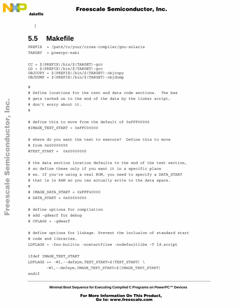
Minimal Boot Sequence for Executing Compiled C Programs on PowerPC™ Devices
Makefile Makefile
}
5.5 MakefilePREFIX = /path/to/your/cross-compiler/gnu-solaris
TARGET = powerpc-eabi
CC = $(PREFIX)/bin/$(TARGET)-gccLD = $(PREFIX)/bin/$(TARGET)-gccOBJCOPY = $(PREFIX)/bin/$(TARGET)-objcopyOBJDUMP = $(PREFIX)/bin/$(TARGET)-objdump
#
# Define locations for the text and data code sections. The bss
# gets tacked on to the end of the data by the linker script,
# don't worry about it.
#
# define this to move from the default of 0xFFF00000
#IMAGE_TEXT_START = 0xFFC00000
# where do you want the text to execute? Define this to move
# from 0x00000000
#TEXT_START = 0x00000000
# the data section location defaults to the end of the text section,
# so define these only if you want it in a specific place
# ex. If you're using a real ROM, you need to specify a DATA_START
# that is in RAM so you can actually write to the data space.
#
# IMAGE_DATA_START = 0xFFF40000
# DATA_START = 0x00050000
# define options for compilation
# add -gdwarf for debug
# CFLAGS = -gdwarf
# define options for linkage. Prevent the inclusion of standard start
# code and libraries.
LDFLAGS = -fno-builtin -nostartfiles -nodefaultlibs -T ld.script
ifdef IMAGE_TEXT_START
LDFLAGS += -Wl,--defsym,TEXT_START=$(TEXT_START) \
-Wl,--defsym,IMAGE_TEXT_START=$(IMAGE_TEXT_START)
endif
Fre
esc
ale
Se
mic
on
du
cto
r, I
Freescale Semiconductor, Inc.
For More Information On This Product, Go to: www.freescale.com
nc
...
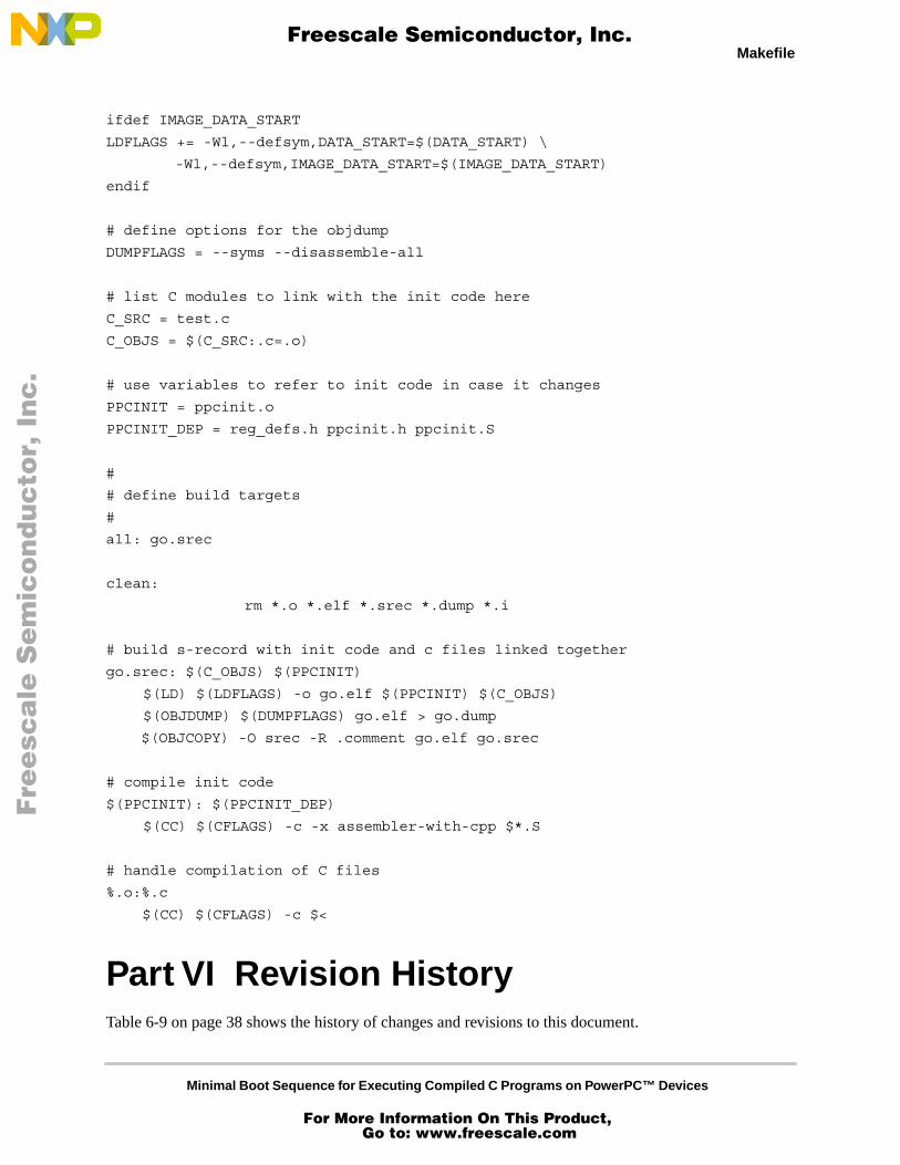
Minimal Boot Sequence for Executing Compiled C Programs on PowerPC™ Devices
Makefile
ifdef IMAGE_DATA_START
LDFLAGS += -Wl,--defsym,DATA_START=$(DATA_START) \
-Wl,--defsym,IMAGE_DATA_START=$(IMAGE_DATA_START)
endif
# define options for the objdump
DUMPFLAGS = --syms --disassemble-all
# list C modules to link with the init code here
C_SRC = test.c
C_OBJS = $(C_SRC:.c=.o)
# use variables to refer to init code in case it changes
PPCINIT = ppcinit.o
PPCINIT_DEP = reg_defs.h ppcinit.h ppcinit.S
#
# define build targets
#
all: go.srec
clean:
rm *.o *.elf *.srec *.dump *.i
# build s-record with init code and c files linked together
go.srec: $(C_OBJS) $(PPCINIT)
$(LD) $(LDFLAGS) -o go.elf $(PPCINIT) $(C_OBJS)
$(OBJDUMP) $(DUMPFLAGS) go.elf > go.dump
$(OBJCOPY) -O srec -R .comment go.elf go.srec
# compile init code
$(PPCINIT): $(PPCINIT_DEP)
$(CC) $(CFLAGS) -c -x assembler-with-cpp $*.S
# handle compilation of C files
%.o:%.c
$(CC) $(CFLAGS) -c $<
Part VI Revision HistoryTable 6-9 on page 38 shows the history of changes and revisions to this document.
Fre
esc
ale
Se
mic
on
du
cto
r, I
Freescale Semiconductor, Inc.
For More Information On This Product, Go to: www.freescale.com
nc
...
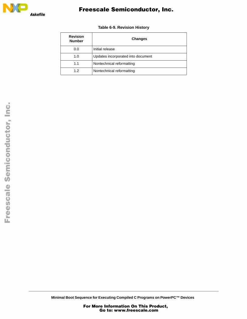
Minimal Boot Sequence for Executing Compiled C Programs on PowerPC™ Devices
Makefile Makefile
Table 6-9. Revision History
Revision Number
Changes
0.0 Initial release
1.0 Updates incorporated into document
1.1 Nontechnical reformatting
1.2 Nontechnical reformatting
Fre
esc
ale
Se
mic
on
du
cto
r, I
Freescale Semiconductor, Inc.
For More Information On This Product, Go to: www.freescale.com
nc
...
Minimal Boot Sequence for Executing Compiled C Programs on PowerPC™ Devices
Makefile
THIS PAGE INTENTIONALLY LEFT BLANK
Fre
esc
ale
Se
mic
on
du
cto
r, I
Freescale Semiconductor, Inc.
For More Information On This Product, Go to: www.freescale.com
nc
...
AN1809
Fre
esc
ale
Se
mic
on
du
cto
r, I
Freescale Semiconductor, Inc.
For More Information On This Product, Go to: www.freescale.com
nc
...