analele universitĂŢii anul xxi, nr. 2, 2014, issn …anale-ing.uem.ro/2014/227.pdf · the use of...
TRANSCRIPT
283
Emanoil Toma
The Use of Current Generators in Electrical Converter Drivesfor Stepper Motors
This paper presents some ways to realize electrical converters for step-per motor drives. The first part analyzes aspects for unipolar steppermotor and use of constant current generators. The second part presentcurrent sources based on peak limiting current trough the inductance ofmotor coil. A complete drive module for bipolar stepper motor was con-ceived and simulation results confirm their functionability.
Keywords: current limiting, micro-stepping, Pspice simulation.
1. Introduction
A stepper motor can be considered a digital electromechanical system whereineach electrical pulse input moves the rotor by a discrete angle called the stepangle and hence the name stepping motor.
Stepper motors are used in commercial and industrial applications because oftheir high reliability, low cost, high torque at low speeds and a simple constructionthat operates in almost every environment [2].
Using a stepper motor is possible to design applications in simple open-loopcontrol system. In this case mechanical actuated system, have low accelerationwith static loads.
Stepper motor haves the advantage of producing high torque at low speed.Stepper motor haves holding torque which allows keeping its position firmly whennot turning. Holding its position is useful for intended application where the motorwill be started and stopped. In this time the force of the mirror’s momentum actingagainst the motor remains present. The results will be unnecessary of brake mec-hanism.
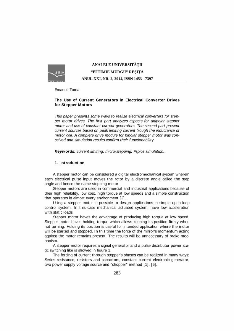
A stepper motor requires a signal generator and a pulse distributor power sta-tic switching like is showed in figure 1.
The forcing of current through stepper’s phases can be realized in many ways:Series resistance, resistors and capacitors, constant current electronic generator,two power supply voltage source and “chopper” method [1], [5].
ANALELE UNIVERSITĂŢII
“EFTIMIE MURGU” REŞIŢA
ANUL XXI, NR. 2, 2014, ISSN 1453 - 7397
284
TranslatorSwitch
Set
Stepper
Motor
Mechanical
Torque
Step
Direction
Figure 1. Stepper motor drive elements
2. Simulations for unipolar stepper motor drivers
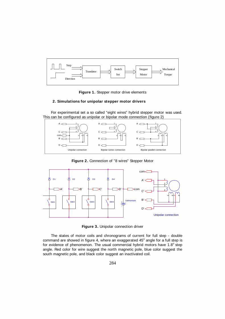
For experimental set a so called "eight wires" hybrid stepper motor was used.This can be configured as unipolar or bipolar mode connection (figure 2)
1
23
4
5 6 7 8
Unipolar connection
1
23
4
5 6 7 8
Bipolar series connection
1
23
4
5 6 7 8
Bipolar parallel connection
A
C
B
D
com
A
D
B
C
A
D
B
C
Figure 2. Connection of "8 wires" Stepper Motor
A' C'
D1 D2 D3 D4
SW1 SW2 SW3 SW4Valimentare
1
23
4
5 6 7 8
Unipolar connection
C'
A'
com
D'
B'
B' D' com
Figure 3. Unipolar connection driver
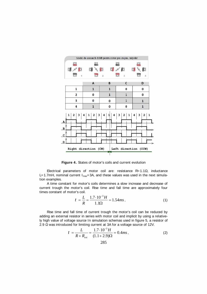
The states of motor coils and chronograms of current for full step - doublecommand are showed in figure 4, where an exaggerated 45o angle for a full step isfor evidence of phenomenon. The usual commercial hybrid motors have 1.8o stepangle. Red color for wire suggest the north magnetic pole, blue color suggest thesouth magnetic pole, and black color suggest an inactivated coil.
285
C
B
A
D
321 214 43 1 3 2 214 4 3 1
Right direction (CW) Left direction (CCW)
Figure 4. States of motor's coils and current evolution
Electrical parameters of motor coil are: resistance R=1.1Ω, inductanceL=1.7mH, nominal current Imax=3A, and these values was used in the next simula-tion examples.
A time constant for motor's coils determines a slow increase and decrease ofcurrent trough the motor's coil. Rise time and fall time are approximately fourtimes constant of motor's coil.
msH
R
L 54.11.1107.1 3
, (1)
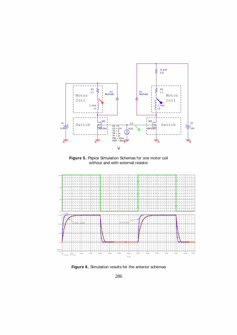
Rise time and fall time of current trough the motor's coil can be reduced byadding an external resistor in series with motor coil and implicit by using a relative-ly high value of voltage source In simulation schemas used in figure 5, a resistor of2.9 Ω was introduced for limiting current at 3A for a voltage source of 12V.
msH
RR
L
ext
4.0)9.21.1(
107.1 3
, (2)
286
0
VCDTD = 0
TF = 1nPW = 20msPER = 40ms
V1 = 0
TR = 1n
V2 = 12V
L11.7mH
R11.1
V1
3.3V
M1
IRFZ44
00
D1MUR405
L21.7mH
R21.1
V2
12V
0
M2
IRFZ44
0
D2MUR405
CD
R_EXT2.9
Motor MotorCoil Coil
Switch Switch
II
V
V
Figure 5. Pspice Simulation Schemas for one motor coilwithout and with external resistor
Ti me
0s 5ms 10ms 15ms 20ms 25ms 30ms 35ms 40ms 45ms 50ms 55ms 60ms 65ms 70msI ( L2) I ( L1)
-1. 0A
0A
1. 0A
2. 0A
3. 0A
SEL>>
wi t hout _R_EXT wi t h_R_EXT
V( CD)0V
4V
8V
12V
Figure 6. Simulation results for the anterior schemas

287
A voltage source with a series resistance begins to have a current source be-havior. Replacing the external resistor with a current source, power dissipated onhim can be reduced [1]. For unipolar motor with four phases is necessary only twoconstant current sources as shown in figure 7.
C'A'
D1 D3 D4
SW1 SW3 SW4V_low
1
23
4
5 6 7 8
Unipolar connection
com_1
A'
C'
B'
D'
D'
com_2
D2
SW2
B'
V_high
I1
I2
I1=I2=Inom
Figure 7. Constant current sources used for unipolar connection
Implementation of constant current source can be realized with operationalamplifier and power transistor like in figure 8, where V_REF can be obtained usinga reference voltage integrated circuit and a voltage divider.
0
V_HIGH
12V M1
IRFZ44
M3
IRFZ44
L1
1.7mHL3
1.7mH
R1
1.1
R3
1.1
0 0
+
- V+
V-
OUT
U1A
LF442/ON
D2
MUR810
D3MUR810
D1
MUR810
C1220N
0 0
COM1
0
V_REF0.3V
0
V_LOW
8V
A C
V1TD = 0
TF = 1nsPW = 20msPER = 40ms
V1 = 0
TR = 1ns
V2 = 12V
0
G1V3
TD = 0
TF = 1nsPW = 20msPER = 40ms
V1 = 12v
TR = 1ns
V2 = 0
0
G3
M4
IRF9540
R4
0.1
VV
V
VV
II
Figure 8. Electrical schema used for Pspice simulation of unipolar stepper motordrive using a constant current source (one pair of motor coils).
288
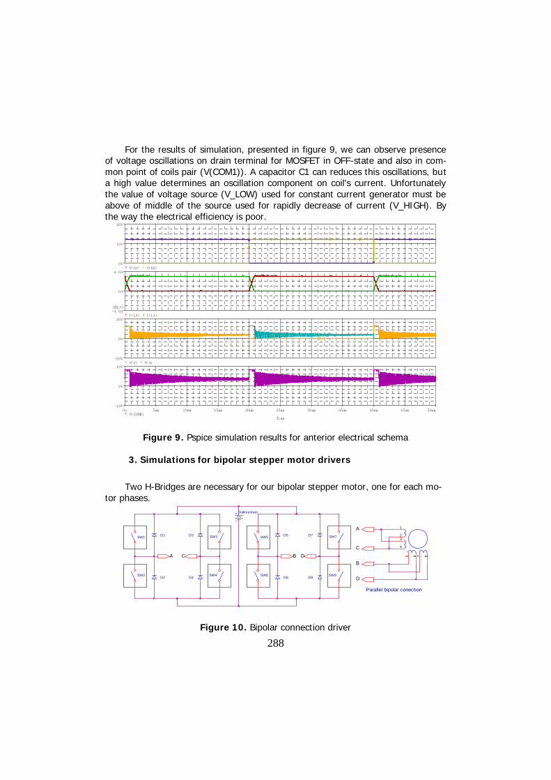
For the results of simulation, presented in figure 9, we can observe presenceof voltage oscillations on drain terminal for MOSFET in OFF-state and also in com-mon point of coils pair (V(COM1)). A capacitor C1 can reduces this oscillations, buta high value determines an oscillation component on coil's current. Unfortunatelythe value of voltage source (V_LOW) used for constant current generator must beabove of middle of the source used for rapidly decrease of current (V_HIGH). Bythe way the electrical efficiency is poor.
Ti me
0s 5ms 10ms 15ms 20ms 25ms 30ms 35ms 40ms 45ms 50msV( COM1)
-10V
0V
10VV( C) V( A)
-20V
0V
20VI ( L3) I ( L1)
-4. 0A
0A
4. 0A
SEL>>
V( G1) V( G3)0V
10V
20V
Figure 9. Pspice simulation results for anterior electrical schema
3. Simulations for bipolar stepper motor drivers
Two H-Bridges are necessary for our bipolar stepper motor, one for each mo-tor phases.
D5
D6
D7
D8
SW5
SW6
SW7
SW8
A BC D
D1
D2
D3
D4
SW1
SW2
SW3
SW4
Valimentare
1
23
4
5 6 7 8
Parallel bipolar conection
C
A
D
B
Figure 10. Bipolar connection driver

289
Parallel connection assures the great couple. The coil's resistance becomes0.55 Ω and inductance remains 1.7 mH. The bridge connection assures energy re-covering when the current decreases. For full step - double command the currentflow permanently trough the each coils. The limited value for our motor is neces-sary to be 4 A, not 2x3 amperes. The states of motor coils and current's chrono-grams are showed in figure 11. Red color for wire suggest the north magnetic poleand blue color suggest the south magnetic pole created by active coils.
1
B-D
A-C
432 21 143 24 3 3 21 14
Left direction (CCW)Right direction (CW)
Figure 11. States of motor's coils and current evolution
+
UH
-
0
0
.R
R
S
S
0
+
-
OUT
ComparatorU_REF
RS Latche
Current Sense
u=i
L R
D1
D2
D3
D4
SW1
SW2
SW3
SW4
Motor CoilDriver
Driver
Driver
Driver
S Q
R Q
PWM Clock
Figure 12. Peak current limiting principia schema for one phase of bipolar motor
290
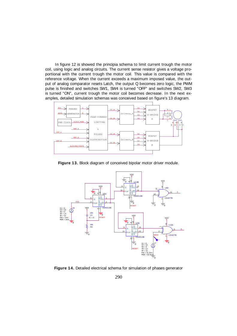
In figure 12 is showed the principia schema to limit current trough the motorcoil, using logic and analog circuits. The current sense resistor gives a voltage pro-portional with the current trough the motor coil. This value is compared with thereference voltage. When the current exceeds a maximum imposed value, the out-put of analog comparator resets Latch, the output Q becomes zero logic, the PWMpulse is finished and switches SW1, SW4 is turned "OFF" and switches SW2, SW3is turned "ON", current trough the motor coil becomes decrease. In the next ex-amples, detailed simulation schemas was conceived based on figure's 13 diagram.
H-BRIDGE
A
B
H-BRIDGE
G5MOSFET
G6
G7
G8
LIMITING
&
PULSES
DISTRIBUTION
PHASES 1
23
4
5 6 7 8
A
B'
A'
C'
C
B DD'PWM Clock CLOCK_PWM
GENERATOR
PAS A
SENS B
PEAK-CURRENT
REF_A
CRT_A
REF_B
CRT_B
BLOCARE_PUNTE
CD_1A
Drivers_A
CD_2A
CD_1B
Drivers_B
CD_2B
G1MOSFET
G2
G3
G4
Figure 13. Block diagram of conceived bipolar motor driver module.
VDD
SE
T8
D9
CLK11
Q13
Q12
VD
D14
VS
S7
RE
SE
T10
U2B
CD4013B
0
RESET
0
VDD
R810k
C210n
IC = 0
VDD
0
A
147
11
13
12
U8D
CD4077B
0
0
V
SENS
V7
TD = 0
TF = 1nPW = 31.5msPER = 62.5ms
V1 = 0
TR = 1n
V2 = 12
0
VDD
0
V6
TD = 0
TF = 1nPW = 1msPER = 2ms
V1 = 0
TR = 1n
V2 = 12
SE
T6
D5
CLK3
Q1
Q2
VD
D14
VS
S7
RE
SE
T4
U5A
CD4013B
0
VDD
PAS
0
B
147
3
1
2
U10A
CD4077B
0RESET
VDD
SE
T8
D9
CLK11
Q13
Q12
VD
D14
VS
S7
RE
SE
T10
U13B
CD4013B
0
RESET0
Figure 14. Detailed electrical schema for simulation of phases generator
291
In figure 13 we can observe the bipolar parallel configuration of our "eightwires" stepper motor with H-Bridge A and drivers A for one motor's coil and H-Bridge B and drivers B for another motor's coil. Five input-signals are necessary forour module: PAS is the signal for step, active on the rising slope. SENS is the signalfor direction of rotation, level "0" for clockwise (CW) direction and level "1" forcounterclockwise (CCW) direction. BLOCARE_PUNTE is signal for standby, the cur-rent trough the motor is cut-off when this signal is on level "0". The two signalsREF_A and REF_B, are the voltage references for peak current limiting techniquedescribed in figure 12. They are positive constant voltages for full-step double-command. These signals must be correlated with PAS signal when micro-steppingcommand is used. They can be easily obtained using a microcontroller and twodigital to analogue converters (DAC) [3, 4].
For simulation, two phase shifted sinusoidal signal and two precise rectifierswas used (figure 17).
Phases generator block, detailed in figure 14, creates signals for the twophases A and B, based on PAS and SENS signals. For CW direction the phase B isbehind the phase A and for CCW direction the phase B is before the phase A.
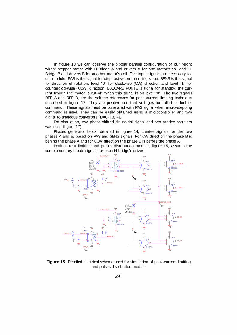
Peak-current limiting and pulses distribution module, figure 15, assures thecomplementary inputs signals for each H-bridge's driver.
0
BLOCARE_PUNTE
0
0
VDD
VDD
VDD
VDD
1
2
147
3
U15A
CD4081B
5
6
147
4
U16B
CD4081B
8
9
147
10
U16C
CD4081B
13
12
147
11
U16D
CD4081B
V8
TD = 42.5m
TF = 1nPW = 20msPER = 113.5ms
V1 = 12
TR = 1n
V2 = 0
0
CD_1A
CD_2A
CD_2B
CD_1B
V
V
V
V
V
0
R7
1k
A
C110nIC = 0
0
comp_ACRT_A
REF_A
OUT7
+2
-3
G1
V+
8V
-4
B/S6B
5U4
LM311
VDD
VDD
0
CLOCK_PWM
VEE
0
R61k
V5
TD = 0
TF = 1nPW = 0.2usPER = 50us
V1 = 0
TR = 1n
V2 = 12
SE
T6
D5
CLK3
Q1
Q2
VD
D14
VS
S7
RE
SE
T4
U9A
CD4013B
VDD
RESET_A
0
0
VDD
147
4
56
U17B
CD4077B
0
B
R10
1k
C310nIC = 0
0
comp_BCRT_B
REF_B
OUT7
+2
-3
G1
V+
8V
-4
B/S6B
5
U6
LM311
VDD
VDD
0
CLOCK_PWM
VEE
VDD
R111k
147
10
89
U17C
CD4077B
0
SE
T6
D5
CLK3
Q1
Q2
VD
D14
VS
S7
RE
SE
T4
U11A
CD4013B
RESET_B
VDD0
0
VDD
147
4
56
U12B
CD4077B
0
VDD
147
10
89
U14C
CD4077B
0
Figure 15. Detailed electrical schema used for simulation of peak-current limitingand pulses distribution module
292
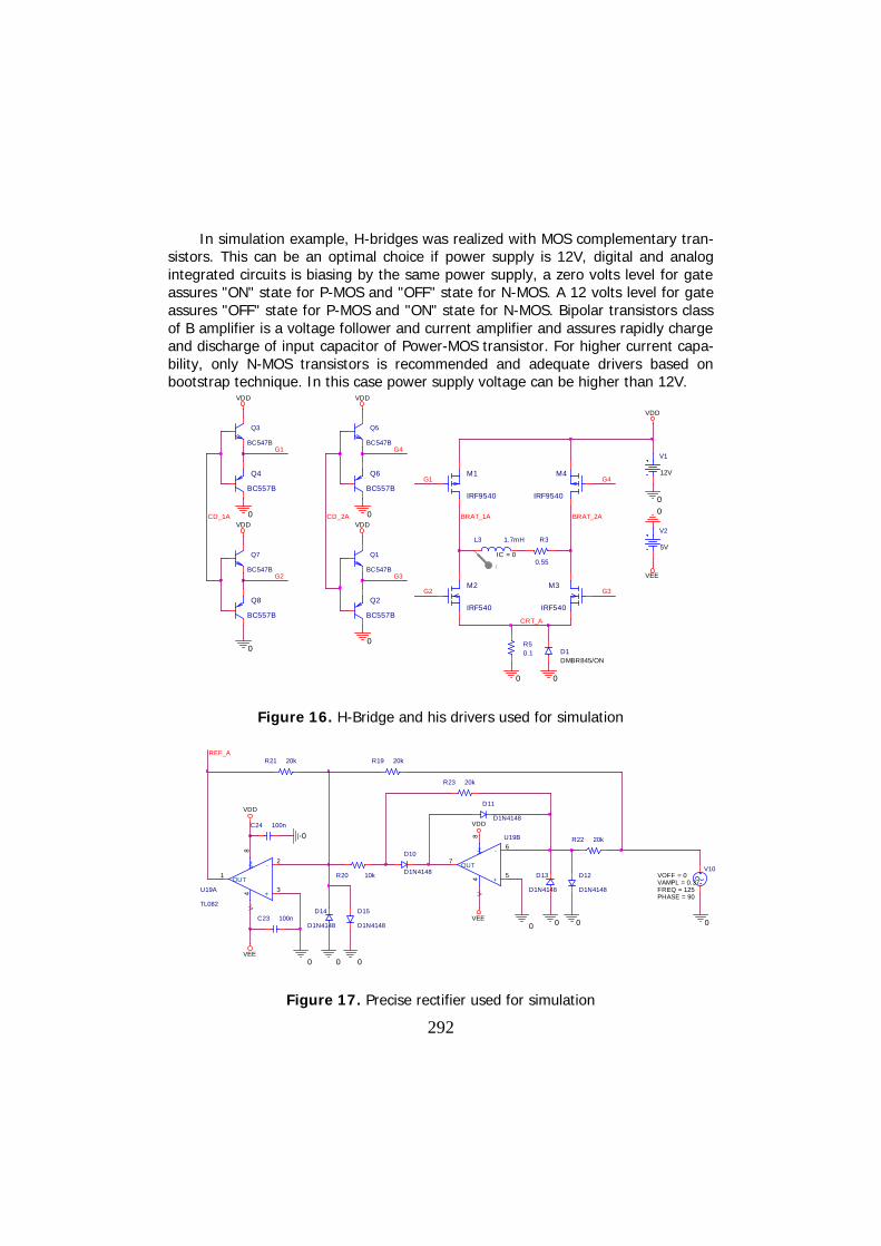
In simulation example, H-bridges was realized with MOS complementary tran-sistors. This can be an optimal choice if power supply is 12V, digital and analogintegrated circuits is biasing by the same power supply, a zero volts level for gateassures "ON" state for P-MOS and "OFF" state for N-MOS. A 12 volts level for gateassures "OFF" state for P-MOS and "ON" state for N-MOS. Bipolar transistors classof B amplifier is a voltage follower and current amplifier and assures rapidly chargeand discharge of input capacitor of Power-MOS transistor. For higher current capa-bility, only N-MOS transistors is recommended and adequate drivers based onbootstrap technique. In this case power supply voltage can be higher than 12V.
CD_1A CD_2A
I
Q5
BC547B
Q6
BC557B
VDD
G4
0
L3 1.7mH
IC = 0
R3
0.55
DMBR845/OND1
0
R50.1
0
BRAT_2ABRAT_1A
G4
CRT_A
G2 G3
G1
VDD
VEE
V2
5V
0
Q1
BC547B
Q2
BC557B
VDD
0
G3
Q3
BC547B
VDD
Q4
BC557B
0
G1V1
12V
0
M1
IRF9540
M4
IRF9540
M2
IRF540
M3
IRF540
Q7
BC547B
VDD
Q8
BC557B
G2
0
Figure 16. H-Bridge and his drivers used for simulation
V10
FREQ = 125VAMPL = 0.37VOFF = 0
PHASE = 90
0
D11
D1N4148
D10
D1N4148 D13
D1N4148
D14
D1N4148 0
R19 20k
R20 10k
R21 20k
VEE
VDD
C23 100n
+3
-2
V+
8V
-4
OUT1
U19A
TL082
+5
-6
V+
8V
-4
OUT7
U19B
VDD
VEE
R22 20k
R23 20k
0
0C24 100n
0
REF_A
00 0
D12
D1N4148
D15
D1N4148
Figure 17. Precise rectifier used for simulation

293
The results of simulation for conceived electrical schema is presented in figure18, where we can observe the sifting of phase B behind the phase A for logic level"1" of SENS signal and before for logic level "0". Sinusoidal waves for currenttrough motor's coils was obtained. Frequency of sinusoidal motor's current is 125Hz for the simulated example. Period of this wave is 8 ms. Four completely steps isexecuted during a sinus period. That implies a 2 ms duration for one step. A com-pletely revolution have 200 steps. Therefore a revolution duration is 400 ms. Thatimplies a speed of 150 RPM. For increase the motor speed is necessary to increasefrequency of reference voltage signals correlated with step signal. But for high fre-quency of sinusoidal current the inductive component of motor voltage becomespredominant.
)( motormotormotormotor LjRIU , (3)
For a speed of 140 RPM the inductive component of motor voltage is:
VLfIU 125.5107.1120242 3 , (4)
For 300 RPM, the inductive voltage component becomes 10.25 volts. Forhigher speed is necessary a higher voltage power supply and preferable N-MOStransistors H-bridges and drivers based on bootstrap technique.
Ti me
80ms 85ms 90ms 95ms 100ms 105ms 110ms 115ms 120ms 125ms 130ms 135ms 140msV( SENS)
0V
10V
20V
SEL>>
80ms 85ms 90ms 95ms 100ms 105ms 110ms 115ms 120ms 125ms 130ms 135ms 140ms
A B
I ( L4)-4. 0A
0A
4. 0AV( REF_A) V( REF_B)
-400mV
0V
400mVI ( L3)
-4. 0A
0A
4. 0A
Figure 18. Simulation results for current evolution trough the stepper motor'scoils for bipolar connection and rectified sinusoidal wave for reference voltage.
294
4. Conclusion
Using a stepper motor is possible to design applications in simple open-loopcontrol system. Stepper motor haves the advantage of producing high torque atlow speed. The time-constant of motor coil determines a slow increase and de-crease of current trough the motor's coil. That limits the maximum speed of motor.For increasing the maximum speed is necessary an external resistor, but electricalefficiency is poor. Using constant current sources the electrical efficiency increase.Linear current sources however have a small electrical efficiency.
Current sources based on chopped technique considerably improving the elec-trical efficiency. For the small motors drives there are many integrated circuits. Forbig motors drives are necessary to use discrete power MOS transistors. A completedrive module for bipolar stepper motor was conceived and simulation results con-firm their functionability. Also this module permits the control of sinusoidal currenttrhough the motor coils.
References
[1] Acarnley P.P., Stepping motors: a guide to modern theory and practice,4-th Edition, The Institution of Engineering and Technology, 2002.
[2] Aranjo B., Soori P.K., Talukder P., Stepper motor drives for robotic ap-plications , Power Engineering and Optimization Conference (PEDCO), 6-7June, Melaka, Malaysia, 2012, 361-366.
[3] Baluta G., Microstepping Mode for Stepper Motor Control, InternationalSymposium on Signals, Circuits and Systems, 12-13 July, Iasi, Romania,2007, Vol. 2, 1-4.
[4] Baluta G., Coteata M., Precision Microstepping System for Bipolar Step-per Motor Control, International Aegean Conference on Electrical Ma-chines and Power Electronics, 10-12 September, Bodrum, Turkey, 2007,259-264.
[5] Toma E., Simion C.M., Bogdan L., Improving of Stepper Motor Beha-viors Used on Cinematic Chain of Machine-Tools for Electrical DischargeMachining, Nonconventional Technologies Review, Volume XVII, no. 2,2013, 97-102.
Address:
As. Drd. Eng. Emanoil Toma, “Lucian Blaga” University of Sibiu, Str.Emil Cioran, nr. 4, 550024, Sibiu, [email protected]