analysis, comparison and study on mitigation of harmonics ... · analysis, comparison and study on...
TRANSCRIPT
Research ArticleVolume 4 Issue 1 - January 2018DOI: 10.19080/JOJMS.2018.04.555628
JOJ Material SciCopyright © All rights are reserved by Satish Karekar
Analysis, Comparison and Study on Mitigation of Harmonics by using Active and Passive Harmonics Filters by using MATLAB SimulationSatish Karekar*Department of Electrical Engineering, Chhattisgarh Swami Vivekan and Technical University, India
Submitted: January 27, 2017; Published: February 02, 2018
*Corresponding author: Satish Karekar, Department of Electrical Engineering, Chhattisgarh Swami Vivekanand Technical University, India; Email:
Introduction
In electrical power system distribution traditional equipment such as rotating machine produces harmonics due to uneven distribution of flux in air gap of rotating machine this tends to no sinusoidal voltage & current generation in rotating machine such as synchronous machine. When we talk about their traditional equipment like transformer overloading of transformer is a causes of harmonic generation [1]. Harmonic are problem arises due to use their Non-linear load. In electrical power system harmonics is a seen for long time but major of problems related to harmonics are come in frame from past few years. In electrical power system distribution traditional equipment such as rotating machine produces harmonics due to uneven distribution of flux in air gap of rotating machine this tends to no sinusoidal voltage & current generation in rotating machine such as synchronous machine. When we talk about their traditional equipment like transformer overloading of transformer is a causes of harmonic generation. Harmonics in Electrical power system is defined as voltage and current which is defined as multiple integers of power system fundamental frequency. Now most of loads are producing are producing except of incandescent bulb light the magnitude of harmonic are varies from load to load [2]. Now in recent days Electrical power quality in electrical energy system has become a major challenge to engineers to maintaining the
sinusoidal waveform in the device. If any distortion come in the waveforms is known as Harmonic Distortion in the system. In Harmonics are the sinusoidal waveform of currents and voltages having frequencies that there is an integer numbers of the frequency at which the supply power system is designed to operate. Harmonics are combined with their fundamental voltage and current can produce waveform distortion. In Harmonic (disturbance) distortion exists due to the non-linear characteristics of devices (system) and loads on the electric power system. Current distortion results as these voltages causes non-linear voltage drops across their system impedance (Z). When their industrial loads like as discharge lighting and electric arc furnaces can causes the harmonic distortion. Their effect of harmonics in the electrical power system includes the loss of data, overheating device or damage to sensitive equipment and more heating of capacitor banks. The Maximum frequency harmonics may also cause interference to nearby which telecommunication system [3].
All these above said problems and identified are severe for the electrical power system, so the harmonic mitigation is the important for both points of view of consumers and utilities end [4]. In Electrical Harmonic filtering technique by using passive filters and it is one of the most used and earliest technologies
JOJ Material Sci 4(1): JOJMS.MS.ID.555627 (2018) 001
Abstract
In this Paper Harmonics Distortion problems counter many of the conventional rules of Electric power system design and operation that consider only the fundamental frequency. The engineer is faced with unfamiliar phenomena that require their unfamiliar tools to analyse, study and unfamiliar equipment to solve. This paper is basically concerned with the Analysis and Study of Harmonics generated and Destroyed by Power Electronic Converters. The investigation and analysis of harmonics has been carried out using Fast Fourier Transform (FFT) to evaluate the Total Harmonic Distortion (THD) of the converters with and without filters. MATLAB/SIMULINK have been employed for their presenting the simulation results because it is well established and recognized simulation software for the power system. Next, the designing of Passive Filter (Single tuned), is carried out after a literature review and have been applied to the converters for harmonics mitigation. In the future, we would proceed to work on Active as well as Passive (combination types) Filters for Harmonics Mitigation. The harmonic distortion solution chosen was to design a passive filter to decrease the distortion by shifting the resonance point of the network. This Paper includes the method to design the passive filter and its impact on efficiency and energy usage.
Keywords: MATLAB software; FFT; Passive filter; Active filter
Abbreviations: FFT: Fast Fourier Transform; THD: Total Harmonic Distortion
How to cite this article: Satish Karekar. Analysis, Comparison and Study on Mitigation of Harmonics by using Active and Passive Harmonics Filters by using MATLAB Simulation. JOJ Material Sci. 2018; 4(1): 555628. DOI: 10.19080/JOJMS.2018.04.555628002
Juniper Online Journal Material Science
present in the system used to address the harmonics mitigation in system. The Passive filters has been used very widely uses because it is very simple and easier designing process and low cost factors. In their harmonics is sinusoidal waveform of currents or voltages having frequencies that are integer numbers of the frequency at which the supply power system is designed to operate. Harmonics are combined with their fundamental voltage and current can produce waveform distortion. In Harmonic (disturbance) distortion exists due to the non-linear characteristics of devices (system) and loads on the electric power system. Current distortion results as these voltages causes non-linear voltage drops across their system impedance. Industrial loads like electric arc furnaces and discharge lighting can cause harmonic distortion. The effect of harmonics in the power system includes the corruption and loss of data, overheating or damage to sensitive equipment and overheating of capacitor banks. The high frequency harmonics may also cause interference to nearby telecommunication system [5]. They supply Real and reactive power to the system while being highly effective in attenuating harmonic components. In Typically, Passive filter banks installed in medium-voltage systems are able to provide satisfactory to reduction in currents and voltages distortions after their planning and design the other solution is the application of active filters [5-7]. Harmonic current is isolated by using harmonic filters in order to protect the electrical equipment from getting damaged due to harmonic voltage distortion [6]. They are also be used to improving the electrical power factor. Harmonic distortion is a growing concern for many customers and for the overall power system due to increasing application of power electronics equipment. Harmonic distortion levels can be found throughout the complete harmonic spectrum, with the magnitudes of each individual harmonic component varying inversely with their position in the spectrum. Furthermore, the phase angle of each component is unique into itself. It is also common to use a single quantity, the total harmonic distortion (THD), as a measure of the magnitude of harmonic distortion. Passive filters exhibit the best relationship cost-benefit among all other mitigation techniques when dealing with low and medium voltage rectifier system [1-4].
Sources of Harmonics
The main sources of harmonics in electric power systems can be categorized as:
a) Magnetization nonlinearities of transformer
b) Rotating machines
c) Arcing devices
d) Semi-conductor based power supply
e) Inverter fed A.C drives
f) Thyristor controlled reactors
g) Phase controllers
h) A.C regulators
Passive Filter
The passive filter consists of elements like inductor, capacitor and resistor for their filtration purpose. Now this makes the passive filter configuration simple and easy to implement. The passive filter is connected with the electrical power distribution system and is series tuned and shunt tuned to present low impedance (Z) to particular harmonics so that these harmonics distortion are diverted from their normal flow path through the filter or is tuned to present high impedance to particular harmonics to stop them from affecting the circuit. The tuning depends on the configuration of the filter designed. The passive filter is a very good choice for constant loads and is a cost effective solution to harmonic reduction and power factor improvement. All these advantages can be lost if the input filter is not properly designed. An oversized input filter unnecessarily adds cost and volume to the design and compromises system performance Proposed Filter Connections This project explains how to design the optimal input filter for a two pulse diode rectifier application using optimization. For a two pulse diode rectifier circuit with low power rating, using a passive filter is best suited. In most of the cases a passive filter involves an RLC combination tuned (shunt and series) to serve the purpose. The proposed RLC filter approach to reduce line current and voltage harmonics generated by two diode rectifier. The simple passive-filter solution is the R-L-C passive filter equivalent circuit. The transfer functions of the filter [8-11].
MATLAB Simulation & Results
These passive filters block the flow of harmonic current and voltage into ac/dc mains, by providing large impedance path at certain harmonic distortion frequencies for which the filter is tuned. Moreover, the harmonic compensation is practically independent of the source impedance. But, passive filter like shunt and series filter suffer due to the reduction in dc link voltage and current due to the voltage drop across the passive filter components at both fundamental as well as fundamental harmonic frequencies. These passive filters block the flow of harmonic current and voltage into ac/dc mains, by providing large impedance path at certain harmonic distortion frequencies for which the filter is tuned. Moreover, the harmonic compensation is practically independent of the source impedance. But, passive filter like shunt and series filter suffer due to the reduction in dc link voltage and current due to the voltage drop across the passive filter components at both fundamental as well as fundamental harmonic frequencies.
The passive filters are used to mitigate power quality problems in ac-dc converter with R-C load. Moreover, apart from mitigating the current harmonics, the passive filters also provide reactive power compensation, thereby, further improving the system performance. Voltage and current source type of harmonic producing loads, generally, passive shunt filters
How to cite this article: Satish Karekar. Analysis, Comparison and Study on Mitigation of Harmonics by using Active and Passive Harmonics Filters by using MATLAB Simulation. JOJ Material Sci. 2018; 4(1): 555628. DOI: 10.19080/JOJMS.2018.04.555628003
Juniper Online Journal Material Science
and passive series filters are recommended. These filter apart from mitigating the current harmonics, also provide limited reactive power compensation and dc bus voltage regulation. The performance of these Passive filters depends heavily depends on the source impedance present in the system or device, as these filter act as sinks for the harmonic currents. On the other hand, for voltage source type harmonic producing loads, the use of the series passive filters is recommended.
Harmonic Filtering Techniques
a. Active Filtering Technique
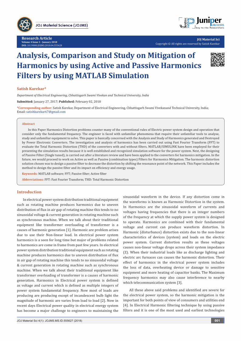
Figure 1: (a) Single- tuned (b) 1st order high-pass (c) 2nd order high-pass (d) 3rd order high-pass (e) C-type [3].
The more sophisticated active filtering concepts operate in a wide frequency range, adjusting their operation to the resultant harmonic spectrum. In this way, they are designed to inject harmonic currents to counterbalance existing harmonic components as they show up in the distribution system [3] (Figure 1).
b. Passive Filters
Passive filters are basically topologies or arrangements of R, L and C elements connected in different combinations to gain desired suppression of harmonics. They are also employed either to passive shunt and passive series the harmonic currents and voltage off the line or to block their flow between parts of the system by tuning the elements to create a resonance at a selected frequency. In passive harmonic filters, preventing the circulation of the unwanted harmonic currents in the power system can be achieved by the usage of a high series impedance to block them (series filter concept) or by diverting the harmonic currents to a low impedance shunt path (shunt filter concept). Series passive filters can be purely inductive type or LC tuned type. AC line reactor filter and DC-link inductor filter are the two purely inductive type filters. AC line reactors offer a considerable magnitude of inductance that alters the shape or form factor the current waveform drawn by the rectifier bridge. They make the current waveform less peaky and discontinuous, resulting in lower current harmonics [12-14].
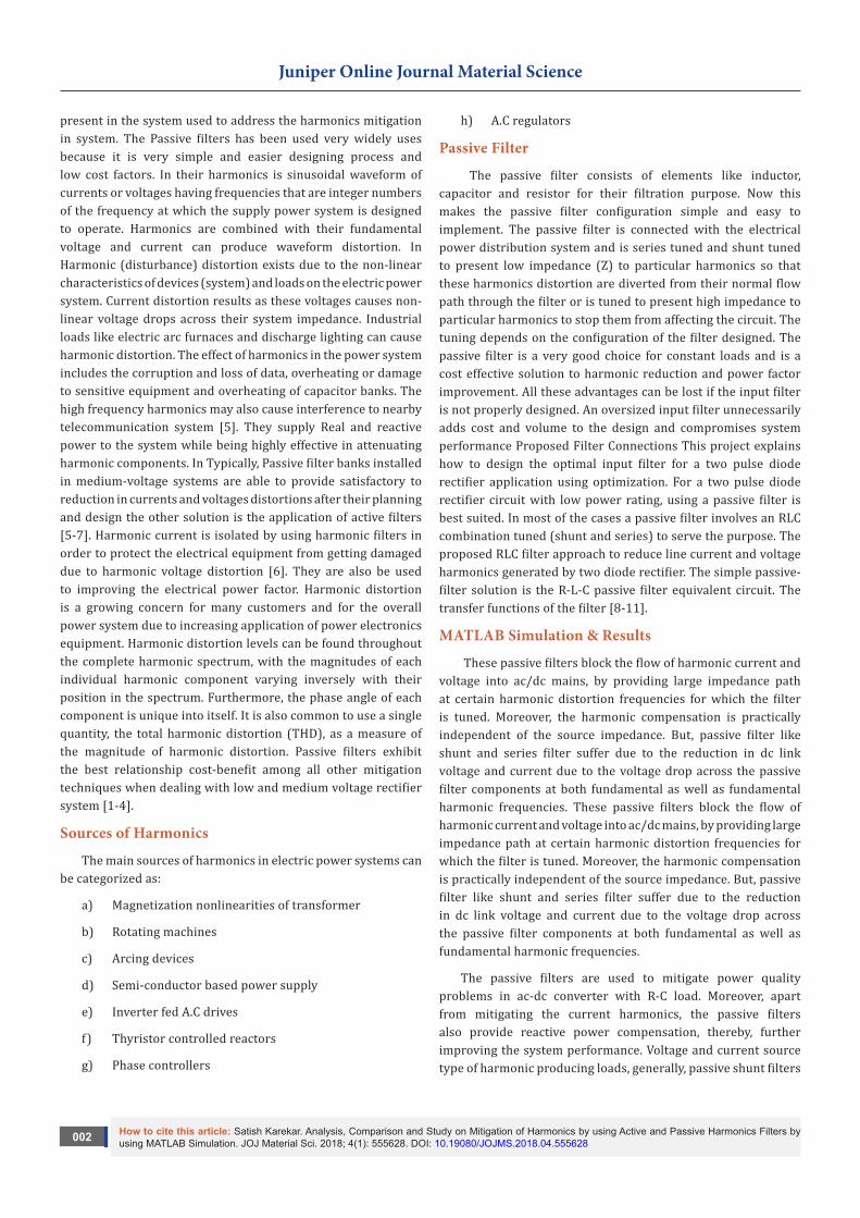
Figure 2: MATLAB based model without Passive Filters.
c. Case 1-Model Running without Harmonic Filters
In the Simulink model, the HVDC rectifier is built up from two 6-pulse thyristor bridges connected in series. The converter is also to connect to the electrical power system with an 11kVA
three-phase transformer (three windings). A 50kVAR resistive load is connected to the DC side through a 0.5H smoothing reactor as shown in Figures 2 & 3. d.
Case 2-Model Running with Double Tuned Harmonic Filters
How to cite this article: Satish Karekar. Analysis, Comparison and Study on Mitigation of Harmonics by using Active and Passive Harmonics Filters by using MATLAB Simulation. JOJ Material Sci. 2018; 4(1): 555628. DOI: 10.19080/JOJMS.2018.04.555628004
Juniper Online Journal Material Science
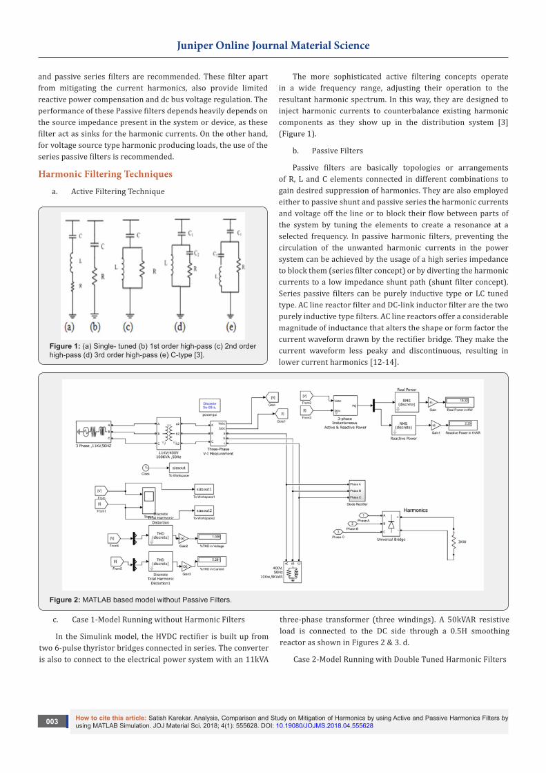
Figure 3: Voltage and Current Waveform without Filters.
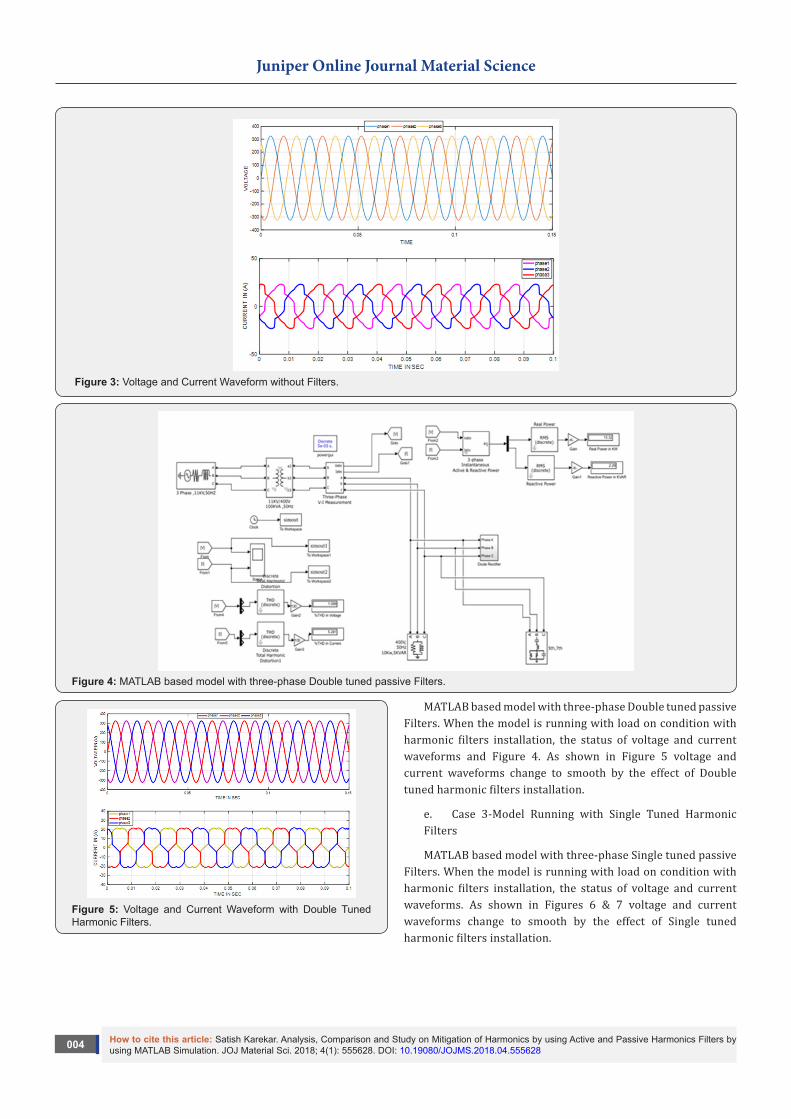
Figure 4: MATLAB based model with three-phase Double tuned passive Filters.
Figure 5: Voltage and Current Waveform with Double Tuned Harmonic Filters.
MATLAB based model with three-phase Double tuned passive Filters. When the model is running with load on condition with harmonic filters installation, the status of voltage and current waveforms and Figure 4. As shown in Figure 5 voltage and current waveforms change to smooth by the effect of Double tuned harmonic filters installation.
e. Case 3-Model Running with Single Tuned Harmonic Filters
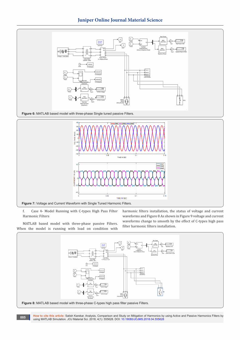
MATLAB based model with three-phase Single tuned passive Filters. When the model is running with load on condition with harmonic filters installation, the status of voltage and current waveforms. As shown in Figures 6 & 7 voltage and current waveforms change to smooth by the effect of Single tuned harmonic filters installation.
How to cite this article: Satish Karekar. Analysis, Comparison and Study on Mitigation of Harmonics by using Active and Passive Harmonics Filters by using MATLAB Simulation. JOJ Material Sci. 2018; 4(1): 555628. DOI: 10.19080/JOJMS.2018.04.555628005
Juniper Online Journal Material Science
Figure 6: MATLAB based model with three-phase Single tuned passive Filters.
Figure 7: Voltage and Current Waveform with Single Tuned Harmonic Filters.
f. Case 4- Model Running with C-types High Pass Filter Harmonic Filters
MATLAB based model with three-phase passive Filters. When the model is running with load on condition with
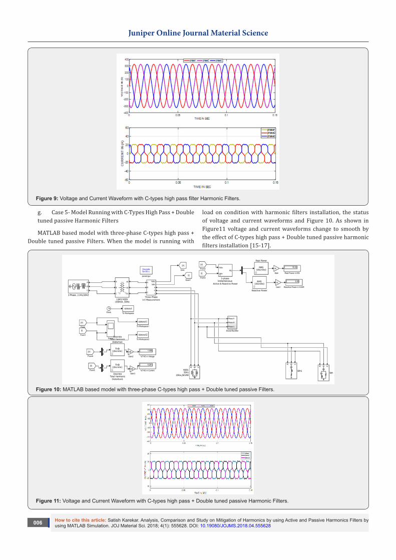
harmonic filters installation, the status of voltage and current waveforms and Figure 8 As shown in Figure 9 voltage and current waveforms change to smooth by the effect of C-types high pass filter harmonic filters installation.
Figure 8: MATLAB based model with three-phase C-types high pass filter passive Filters.
How to cite this article: Satish Karekar. Analysis, Comparison and Study on Mitigation of Harmonics by using Active and Passive Harmonics Filters by using MATLAB Simulation. JOJ Material Sci. 2018; 4(1): 555628. DOI: 10.19080/JOJMS.2018.04.555628006
Juniper Online Journal Material Science
Figure 9: Voltage and Current Waveform with C-types high pass filter Harmonic Filters.
g. Case 5- Model Running with C-Types High Pass + Double tuned passive Harmonic Filters
MATLAB based model with three-phase C-types high pass + Double tuned passive Filters. When the model is running with
load on condition with harmonic filters installation, the status of voltage and current waveforms and Figure 10. As shown in Figure11 voltage and current waveforms change to smooth by the effect of C-types high pass + Double tuned passive harmonic filters installation [15-17].
Figure 10: MATLAB based model with three-phase C-types high pass + Double tuned passive Filters.
Figure 11: Voltage and Current Waveform with C-types high pass + Double tuned passive Harmonic Filters.
How to cite this article: Satish Karekar. Analysis, Comparison and Study on Mitigation of Harmonics by using Active and Passive Harmonics Filters by using MATLAB Simulation. JOJ Material Sci. 2018; 4(1): 555628. DOI: 10.19080/JOJMS.2018.04.555628007
Juniper Online Journal Material Science
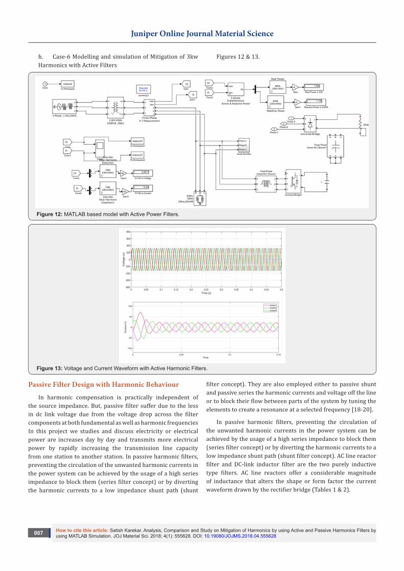
h. Case-6 Modelling and simulation of Mitigation of 3kw Harmonics with Active Filters
Figures 12 & 13.
Figure 12: MATLAB based model with Active Power Filters.
Figure 13: Voltage and Current Waveform with Active Harmonic Filters.
Passive Filter Design with Harmonic Behaviour
In harmonic compensation is practically independent of the source impedance. But, passive filter suffer due to the less in dc link voltage due from the voltage drop across the filter components at both fundamental as well as harmonic frequencies In this project we studies and discuss electricity or electrical power are increases day by day and transmits more electrical power by rapidly increasing the transmission line capacity from one station to another station. In passive harmonic filters, preventing the circulation of the unwanted harmonic currents in the power system can be achieved by the usage of a high series impedance to block them (series filter concept) or by diverting the harmonic currents to a low impedance shunt path (shunt
filter concept). They are also employed either to passive shunt and passive series the harmonic currents and voltage off the line or to block their flow between parts of the system by tuning the elements to create a resonance at a selected frequency [18-20].
In passive harmonic filters, preventing the circulation of the unwanted harmonic currents in the power system can be achieved by the usage of a high series impedance to block them (series filter concept) or by diverting the harmonic currents to a low impedance shunt path (shunt filter concept). AC line reactor filter and DC-link inductor filter are the two purely inductive type filters. AC line reactors offer a considerable magnitude of inductance that alters the shape or form factor the current waveform drawn by the rectifier bridge (Tables 1 & 2).
How to cite this article: Satish Karekar. Analysis, Comparison and Study on Mitigation of Harmonics by using Active and Passive Harmonics Filters by using MATLAB Simulation. JOJ Material Sci. 2018; 4(1): 555628. DOI: 10.19080/JOJMS.2018.04.555628008
Juniper Online Journal Material Science
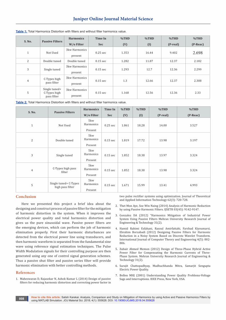
Table 1: Total Harmonics Distortion with filters and without filter harmonics value.
S. No. Passive FiltersHarmonics
W/o Filter
Time In
Sec
%THD
(V)
%THD
(I)
%THD
(P-real)
%THD
(P-Reac)
1 Not Used3kw Harmonics
present0.25 sec 1.353 16.44 9.402 2.698
2 Double tuned Double tuned 0.15 sec 1.282 11.87 12.37 2.182
3 Single tuned3kw Harmonics
present0.15 sec 1.293 12.7 12.36 2.299
4 C-Types high pass filter
3kw Harmonics
present0.15 sec 1.3 12.66 12.37 2.308
5Single tuned+ C-Types high
pass filter
3kw Harmonics
present0.15 sec 1.168 12.56 12.36 2.33
Table 2: Total Harmonics Distortion with filters and without filter harmonics value.
S. No. Passive FiltersHarmonics
W/o Filter
Time In
Sec
%THD
(V)
%THD
(I)
%THD
(P-real)
%THD
(P-Reac)
1 Not Used5kw
Harmonics
Present0.25 sec 1.861 18.28 14.00 3.527
2 Double tuned5kw
Harmonics
Present0.15 sec 1.819 17.72 13.98 3.197
3 Single tuned5kw
Harmonics
Present0.15 sec 1.852 18.38 13.97 3.324
4 C-Types high pass filter
5kw Harmonics
Present0.15 sec 1.852 18.38 13.98 3.324
5 Single tuned+ C-Types high pass filter
5kw Harmonics
Present0.15 sec 1.671 15.99 13.41 4.993
Conclusion
Here we presented this project a brief idea about the designing and construct process of passive filter for the mitigation of harmonic distortion in the system. When it improves the electrical power quality and total harmonics distortion and gives us the pure sinusoidal wave. Passive power filters are the emerging devices, which can perform the job of harmonic elimination properly. First their harmonic disturbances are detected from the electrical power line using transducers, and then harmonic waveform is separated from the fundamental sine wave using reference signal estimation techniques. The Pulse Width Modulation signals for their controlling purpose are then generated using any one of control signal generation schemes. Thus a passive shut filter and passive series filter will provide harmonic elimination with better controlling methods.
References1. Maheswaran D, Rajasekar N, Ashok Kumar L (2014) Design of passive
filters for reducing harmonic distortion and correcting power factor in
two pulse rectifier systems using optimization. Journal of Theoretical and Applied Information Technology 62(3): 720-728.
2. Thet Mon Aye, Soe Win Naing (2014) Analysis of Harmonic Reduction by using Passive Harmonic Filters. IJSETR 03(45): 9142-9147.
3. Gonzalez DA (2012) “Harmonics Mitigation of Industrial Power System Using Passive Filters Mehran University Research Journal of Engineering & Technology 31(2).
4. Hamid Rahimi Esfahani, Rasoul Amirfattahi, Farshad Kiyoumarsi, Ebrahim Borzabadi (2012) Designing Passive Filters for Harmonic Reduction in a Noisy System Based on Discrete Wavelet Transform. International Journal of Computer Theory and Engineering 4(5): 802-806.
5. Zubair Ahmed Memon (2012) Design of Three-Phase Hybrid Active Power Filter for Compensating the Harmonic Currents of Three-Phase System. Mehran University Research Journal of Engineering & Technology 31(2).
6. Surajit Chattopadhyay, Madhuchhanda Mitra, Samarjit Sengupta Electric Power Quality.
7. Bollen MHJ (2001) Understanding Power Quality Problems-Voltage Sags and Interruptions. IEEE Press, New York, USA.
How to cite this article: Satish Karekar. Analysis, Comparison and Study on Mitigation of Harmonics by using Active and Passive Harmonics Filters by using MATLAB Simulation. JOJ Material Sci. 2018; 4(1): 555628. DOI: 10.19080/JOJMS.2018.04.555628009
Juniper Online Journal Material Science
8. Mohan N, Undeland TM, Robbins WP (1989) Power Electronics-Converters, Applications, and Design. John Wiley & Sons, Inc, New York, USA.
9. Taylor JT, Huang Q (1997) Handbook of Electrical Filters. Boca Raton, Florida.
10. Yacamini R (1996) Power System Harmonics. 185-193.
11. Bose BK (1992) Modern Power Electronics Evolution, Technology and Applications. IEEE Industrial Electronics Society, New York, USA.
12. Akagi (1997) Control Strategy and site selection of a shunt active filter for damping of harmonies propagation in power distribution systems. IEEE Trans on Power Delivery 12(1): 354-363.
13. Harmonic analysis Russell Brown (2001) Department of Mathematics, University of Kentucky Lexington, Kentucky.
14. Ali I Maswood, Haque MH (2002) Harmonics Sources Effects and Mitigation Techniques. School of EEE, Nanyang Technological University Second International Conference on Electrical and Computer Engineering ICECE p: 26-28.
15. Bhattacharya S, Po-Tai Cheng, Divan DM (1997) Hybrid Solutions for improving Passive Filter Performance in high power Applications. IEEE Trans. on Industry Applications 33(3): 732-747.
16. Update of Harmonic Standard IEEE-519 (1991) IEEE Recommended Practices and Requirements for Harmonic Control in Power Systems.
17. Swamy MM (1995) Passive Harmonic Filter Systems for Variable Frequency Drives. US Patent no: 5,444,609.
18. Girgis AA (1989) Measurement and Characterization of Harmonic and High Frequency Distortion for a Large Industrial Load. IEEE Transactions on Power Delivery 70: 427-434.
19. Takahashi, Omura Y (1992) High power active filter using LC tuned filter. JIEE Trans Ind Appl D 112 (9): 823–828
20. Roger C Dugan, Mark F McGranaghan, Surya Santoso, H Wayne Beaty (2002) Electrical Power System Quality McGraw Hill pp. 324-425.
Your next submission with Juniper Publishers will reach you the below assets
• Quality Editorial service• Swift Peer Review• Reprints availability• E-prints Service• Manuscript Podcast for convenient understanding• Global attainment for your research• Manuscript accessibility in different formats
( Pdf, E-pub, Full Text, Audio) • Unceasing customer service
Track the below URL for one-step submission https://juniperpublishers.com/online-submission.php
This work is licensed under CreativeCommons Attribution 4.0 LicensDOI: 10.19080/JOJMS.2018.04.555628