journal of engineering mitigation of harmonics in a three-phase
TRANSCRIPT

International Journal of Engineering and Technology Volume 2 No. 5, May, 2012
ISSN: 2049-3444 © 2012 – IJET Publications UK. All rights reserved. 761
Mitigation of Harmonics in a Three-Phase, Four-Wire Distribution System
using a System of Shunt Passive Filters
Erwin Normanyo Department of Electrical and Electronic Engineering,
Faculty of Engineering, University of Mines and Technology, Tarkwa, Ghana
ABSTRACT
Three-phase four-wire distribution systems are very common and widely used in commercial and industrial installations and therefore
power systems harmonics is an area that merits a great deal of attention. Advancement in semiconductor devices has fuelled an increase
in the use of non-linear loads which are the main causes of harmonic distortion in three-phase, four-wire distribution systems. Mitigation
of harmonics in three-phase, four-wire electrical power distribution systems that supply balanced and unbalanced non-linear loads was
therefore conducted. Giving consideration to the 5th
and 7th
order harmonics, the mitigation system was modeled and simulated using
Matlab/Simulink. Three experiments were conducted for each order of harmonics. Simulation results showed that a better filtering ability
is obtained when the characteristic impedance of the shunt passive filter is small and also for a larger resonance frequency also gave
better filtering ability. Implementation of the developed model in a three-phase, four-wire power distribution systems promises an
absolute minimum of the harmonics content and thus improved harmonics-focused power quality. This paper proposes an approach to
compensate for harmonics in a three-phase four-wire power distribution system. The mitigation principle is described, and some
interesting filtering characteristics are discussed.
Keywords: Power distribution system, harmonics, shunt passive filter, total harmonic distortion (THD).
1. INTRODUCTION
Power quality (PQ) problems in power utility distribution
systems are not new. Advances in semiconductor device
technology have fuelled a revolution in power electronics over
the past decade, and there are indications that this trend will
continue. However, power electronics based equipments which
include adjustable-speed motor drives, electronic power
supplies, DC motor drives, battery chargers, electronic ballasts
are responsible for the rise in power quality related problems.
These nonlinear loads appear to be prime sources of harmonic
distortion in a power distribution system (Salam et al, 2006).
Power quality is an important problem that a power system has
to deal with to provide its consumers with reliable and
economical power supply. Three-phase, four-wire distribution
systems are very common and widely used in commercial and
industrial installations and therefore power systems harmonics
is an area that merits a great deal of attention. Today’s electric
power systems are connected to many non-linear loads. These
include static power converters, arc discharge devices,
electronic control equipment by way of semiconductor devices,
saturated magnetic devices and rotating machines. The
characteristics of these non-linear loads inevitably change the
sinusoidal nature of the a.c. power current, resulting in the flow
of harmonic current in the a.c. power system.
Harmonics are currents or voltages with frequencies that are
integer multiples of the fundamental power frequency. In
modern test equipment today harmonics can be measured up to
the 63rd
harmonic source. When harmonic frequencies are
prevalent, electrical power panels and transformers become
mechanically resonant to the magnetic fields generated by
higher frequency harmonics. Harmonic frequencies from the 3rd
to the 25th
are the most common range of frequencies measured
in electrical distribution systems (Ramos, 2007). According to
Ashok (2002), the effects of harmonics on distribution systems
could be summarised thus: cable heating and degradation of
dielectric strength; increase in copper losses and stray flux
losses in transformers; additional heating, losses and increased
dielectric stress in capacitor banks; improper relay operation;
noise and malfunctioning of control systems. Total Harmonic
Distortion (THD) can be used to describe voltage or current
distortion and thus harmonics. It is calculated using Equation
(1).
THD (%) =
(1)
where IDn is magnitude of the nth
harmonic as a percentage of
the fundamental.
International Journal of Engineering and Technology (IJET) – Volume 2 No. 5, May, 2012
ISSN: 2049-3444 © 2012 – IJET Publications UK. All rights reserved. 762
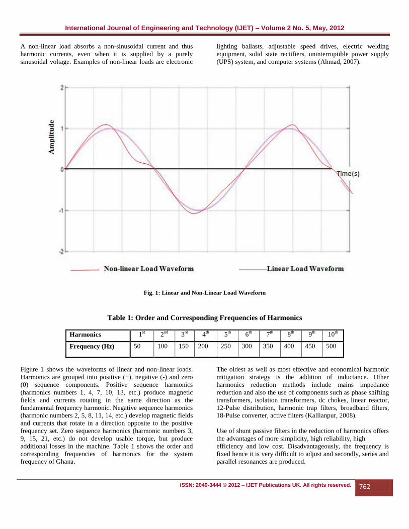
A non-linear load absorbs a non-sinusoidal current and thus
harmonic currents, even when it is supplied by a purely
sinusoidal voltage. Examples of non-linear loads are electronic
lighting ballasts, adjustable speed drives, electric welding
equipment, solid state rectifiers, uninterruptible power supply
(UPS) system, and computer systems (Ahmad, 2007).
Fig. 1: Linear and Non-Linear Load Waveform
Table 1: Order and Corresponding Frequencies of Harmonics
Harmonics 1st 2
nd 3
rd 4
th 5
th 6
th 7
th 8
th 9
th 10
th
Frequency (Hz) 50 100 150 200 250 300 350 400 450 500
Figure 1 shows the waveforms of linear and non-linear loads.
Harmonics are grouped into positive (+), negative (-) and zero
(0) sequence components. Positive sequence harmonics
(harmonics numbers 1, 4, 7, 10, 13, etc.) produce magnetic
fields and currents rotating in the same direction as the
fundamental frequency harmonic. Negative sequence harmonics
(harmonic numbers 2, 5, 8, 11, 14, etc.) develop magnetic fields
and currents that rotate in a direction opposite to the positive
frequency set. Zero sequence harmonics (harmonic numbers 3,
9, 15, 21, etc.) do not develop usable torque, but produce
additional losses in the machine. Table 1 shows the order and
corresponding frequencies of harmonics for the system
frequency of Ghana.
The oldest as well as most effective and economical harmonic
mitigation strategy is the addition of inductance. Other
harmonics reduction methods include mains impedance
reduction and also the use of components such as phase shifting
transformers, isolation transformers, dc chokes, linear reactor,
12-Pulse distribution, harmonic trap filters, broadband filters,
18-Pulse converter, active filters (Kallianpur, 2008).
Use of shunt passive filters in the reduction of harmonics offers
the advantages of more simplicity, high reliability, high
efficiency and low cost. Disadvantageously, the frequency is
fixed hence it is very difficult to adjust and secondly, series and
parallel resonances are produced.

International Journal of Engineering and Technology (IJET) – Volume 2 No. 5, May, 2012
ISSN: 2049-3444 © 2012 – IJET Publications UK. All rights reserved. 763
Efforts aimed at harmonics mitigation have been reported in the
recent literature. These include the transformer based methods:
use wye-zig-zag transformers to reduce triplen harmonic
currents in the neutral conductors of a three-phase 415/240V
distribution system (Omar et al, 2010); investigation of the
effects of harmonic distortion of load current and voltages on
distribution transformers using a K-FACTOR transformer
(Jayasinghe et al, 2003); analysis of harmonic distortion effects
and their mitigation in distribution systems introducing
effective techniques by the application of phase shifting
transformers (Attia et al, 2010). Ahmad (2007) employed four
selected passive mitigation devices namely wye-zigzag
transformer, neutral 3rd
harmonic blocking series filter, 3-phase
3rd
harmonic blocking series filter and a 3-phase 3rd
harmonic
trap shunt filter to mitigate triplen harmonic distortion in 3-
phase, 4-wire electrical distribution system. Another mitigation
technique employs artificial intelligence and algorithms: Pairoj
and Somyot (2010) employed cost function, Particle Swarm
Optimisation (PSO) using Artificial Neural Network (ANN) to
approximate the switching angles from sets of optimal angles
evolved by PSO in the design of a Pulse Width Modulation
(PWM) AC voltage controller minimising total Current
Harmonic Distortion (THDi); Ghiasi et al (2002) economically
determined the location and size of passive filters in distribution
networks using genetic algorithm; Du et al (2004) worked on an
optimal Total Harmonic Distortion (THD) control algorithm
with implementation using Altera FLEX 10K Field
Programmable Gate Array (FPGA) at 8 µs control resolution,
for cascaded H-bridges multilevel converter control with
unequal DC sources. Low order harmonics such as the 5th
,
7th
,11th
and 13th
are eliminated using elimination theory whilst
magnitudes and phases of residual higher harmonics are
computed and subtracted from the original output voltage
waveform to eliminate the higher harmonics. The Newton
climbing method was successfully used to eliminate higher
order harmonics whilst low order harmonics are dealt with
using either resultant theory applied to transcendental equations
(Du et al, 2005; 2006) or use reduced switching-frequency
active-harmonic-elimination method (Du et al, 2008). Active
power filter (APF) harmonics-elimination technologies were
reported by Key and Lai (2001) and Salam et al (2006). A
combined series active filter and shunt passive filters quite
different from the conventional shunt and series active power
filters to give better filtering characteristics and lower initial
and running costs (Mahalekshmi , 2010; Pinto et al, 2007;
Vijayakumar and Eswarlal, 2009).
Employed in harmonics suppression are mathematical modeling
or a simulation model (Degroote et al, 2007; Piel and
Carnovale, 2004). Huang (1997) employed a constant duty
cycle with sixth-order harmonic injection to suppress the
dominant fifth-order harmonics in the input currents. Caumes
et al (2005) investigated carrier-envelope phase effects in high-
order harmonic generation using a single-shot method.
Ortmeyer et al (2000) proposed a 5-step planning methodology
for distribution system harmonic filtering intended for use on
radial distribution systems with no large harmonic sources.
Mindykowski et al (2007) focused attention on the problems of
power quality in systems with varying frequency equipped with
passive harmonic filters where the main differences between the
ship system and land network were considered. Ray and
Hapeshis (2005) gave an overview of harmonic considerations
for designing industrial and commercial electric power
distribution systems.
Morán et al (2007) looked at different power quality problems
in distribution systems and their solutions with power
electronics based equipment. Shunt, hybrid and series active
power filters were described showing their compensation
characteristics and principles of operation. Different power
circuit topologies and control schemes for each type of active
power filter were analysed. Simulations and experimentals
proved the compensation characteristics of each topology with
the respective control scheme. Ryckaert et al (2004) discussed
the harmonic mitigation potential of a resistive shunt harmonic
impedance (SHI) installed between the middle and the end of
the feeder. Non-linear loads were concentrated in single nodes
whereas the linear loads were disconnected to obtain the worst
case for voltage distortion. Mansoor et al (2007) proposed an
LCL-filter-based hybrid active power filter topology for
harmonic mitigation of a 10/0.4kV residential distribution
system. It achieved better switching ripples attenuation and
significant improvement in the phase margin of the power stage
at higher frequency. Adaptive linear neural network
(ADALINE) is applied for individual harmonic component
extraction and the estimated signals are used for selective
harmonic elimination (SHE) purposes. Laboratory experiments
and field tests confirmed the feasibility and effectiveness of the
proposed system. Guesswork was taken out of harmonic
filtering by giving the theory of operation of various passive
harmonic mitigation techniques and demonstrating their typical
real life performance (Anon, 2005).
The objectives of this paper are to mitigate 5th
and 7th
order
harmonics in a three-phase four- wire power distribution
system, reduce power system losses due to harmonics and
propose a mitigation principle that will produce much better
filtering characteristics for a power system.
2. MATERIALS AND METHODS
A simulation approach is adopted in this study. For non-linear
loads, the shunt passive filter and the mitigation system were
determined using the concept of mitigation of the predominate
harmonic order in the system. An experimental set up was
created based on mitigation of the 5th
and 7th
order harmonics.
A simulation circuit diagram is developed by varying the filter
parameters in accordance with the experimental set up.
2.1 Materials
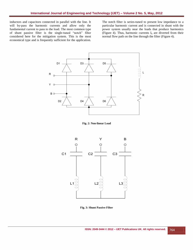
A six diode rectifier bridge is considered as the non-linear load
(Figure 2). The shunt passive filters (Figure 3) consist of
International Journal of Engineering and Technology (IJET) – Volume 2 No. 5, May, 2012
ISSN: 2049-3444 © 2012 – IJET Publications UK. All rights reserved. 764
inductors and capacitors connected in parallel with the line. It
will by-pass the harmonic currents and allow only the
fundamental current to pass to the load. The most common type
of shunt passive filter is the single-tuned “notch” filter
considered here for the mitigation system. This is the most
economical type and is frequently sufficient for the application.
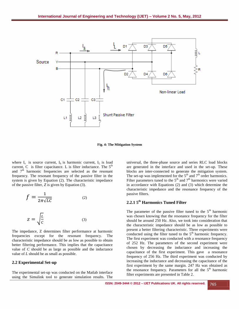
The notch filter is series-tuned to present low impedance to a
particular harmonic current and is connected in shunt with the
power system usually near the loads that produce harmonics
(Figure 4). Thus, harmonic currents Ih are diverted from their
normal flow path on the line through the filter (Figure 4).
Fig. 2: Non-linear Load
Fig. 3: Shunt Passive Filter
International Journal of Engineering and Technology (IJET) – Volume 2 No. 5, May, 2012
ISSN: 2049-3444 © 2012 – IJET Publications UK. All rights reserved. 765
Fig. 4: The Mitigation System
where Is is source current, Ih is harmonic current, IL is load
current, C is filter capacitance. L is filter inductance. The 5th
and 7th
harmonic frequencies are selected as the resonant
frequency. The resonant frequency of the passive filter in the
system is given by Equation (2). The characteristic impedance
of the passive filter, Z is given by Equation (3).
(2)
(3)
The impedance, Z determines filter performance at harmonic
frequencies except for the resonant frequency. The
characteristic impedance should be as low as possible to obtain
better filtering performance. This implies that the capacitance
value of C should be as large as possible and the inductance
value of L should be as small as possible.
2.2 Experimental Set-up
The experimental set-up was conducted on the Matlab interface
using the Simulink tool to generate simulation results. The
universal, the three-phase source and series RLC load blocks
are generated in the interface and used in the set-up. These
blocks are inter-connected to generate the mitigation system.
The set-up was implemented for the 5th
and 7th
order harmonics.
Filter parameters tuned to the 5th
and 7th
harmonics were varied
in accordance with Equations (2) and (3) which determine the
characteristic impedance and the resonance frequency of the
passive filters.
2.2.1 5th
Harmonics Tuned Filter
The parameter of the passive filter tuned to the 5th
harmonic
was chosen knowing that the resonance frequency for the filter
should be around 250 Hz. Also, we took into consideration that
the characteristic impedance should be as low as possible to
present a better filtering characteristic. Three experiments were
conducted using the filter tuned to the 5th harmonic frequency.
The first experiment was conducted with a resonance frequency
of 252 Hz. The parameters of the second experiment were
chosen by decreasing the inductance and increasing the
capacitance of the first experiment. This gave a resonance
frequency of 256 Hz. The third experiment was conducted by
increasing the inductance and decreasing the capacitance of the
first experiment by the same margin. 247 Hz was obtained as
the resonance frequency. Parameters for all the 5th
harmonic
filter experiments are presented in Table 2.

International Journal of Engineering and Technology (IJET) – Volume 2 No. 5, May, 2012
ISSN: 2049-3444 © 2012 – IJET Publications UK. All rights reserved. 766
2.2.2 7th
Harmonic Tuned Filter
Similarly, three experiments were conducted for the passive
filter parameters tuned to the 7th
harmonics taking cognisance of
a filter resonance frequency around 350 Hz. Also, low
characteristic impedance is required for a better filtering
characteristic. 356 Hz is the resonance frequency for the first
experiment. Similarly parameters of the second experiment are
chosen by decreasing the inductance and increasing the
capacitance of the first experiment. This is supposed to give a
resonance frequency of 364 Hz. Parameters for the last
experiment are chosen by increasing the inductance and
decreasing the capacitance of the first experiment by the same
margin as in the second experiment. The resonance frequency
was 348 Hz. Parameters for all the 7th
harmonics filter
experiments are presented in Table 3. The passive filter tuned
to the 7th
harmonic frequency is expected to offer less
impedance to the 11th
and 13th
harmonic components, compared
to that tuned to the 5th
harmonic frequency (Mindykwoski et al,
2007).
Table 2: System Parameters for 5th
Harmonic Filter
System Parameters First Experiment Second Experiment Third Experiment
Source frequency 50 Hz 50 Hz 50 Hz
Source voltage (phase to phase) 415 V 415 V 415 V
Source impedance 0.5 Ω and 1 mH 0.5 Ω and 1 mH 0.5 Ω and 1 mH
Passive filter impedance 100 µF and 4 mH 101.5 µF and 3.8
mH 98.5 µF and 4.2 mH
Passive filter resonance frequency 252 Hz 256 Hz 247 Hz
Passive filter characteristic impedance 6.32 Ω 6.12 Ω 6.53 Ω
Load impedance 10.6 Ω and 58.2 mH 10.6 Ω and 58.2 mH 10.6 Ω and 58.2 mH
Table 3: System Parameters for 7th
Harmonic Filter
System Parameters First Experiment Second Experiment Third Experiment
Source frequency 50 Hz 50 Hz 50 Hz
Source voltage (phase to phase) 415 V 415 V 415 V
Source impedance 0.5 Ω and 1 mH 0.5 Ω and 1 mH 0.5 Ω and 1 mH
Passive filter impedance 100 µF and 2 mH 100.5 µF and 1.9 mH 99.5 µF and 2.1 mH
Passive filter resonance frequency 356 Hz 364 Hz 348 Hz
Passive filter characteristic impedance 4.47 Ω 4.35 Ω 4.59 Ω
Load impedance 10.6 Ω and 58.2 mH 10.6 Ω and 58.2 mH 10.6 Ω and 58.2 mH
International Journal of Engineering and Technology (IJET) – Volume 2 No. 5, May, 2012
ISSN: 2049-3444 © 2012 – IJET Publications UK. All rights reserved. 767
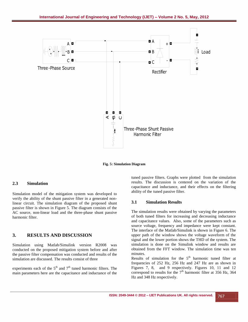
Fig. 5: Simulation Diagram
2.3 Simulation
Simulation model of the mitigation system was developed to
verify the ability of the shunt passive filter in a generated non-
linear circuit. The simulation diagram of the proposed shunt
passive filter is shown in Figure 5. The diagram consists of the
AC source, non-linear load and the three-phase shunt passive
harmonic filter.
3. RESULTS AND DISCUSSION
Simulation using Matlab/Simulink version R2008 was
conducted on the proposed mitigation system before and after
the passive filter compensation was conducted and results of the
simulation are discussed. The results consist of three
experiments each of the 5th
and 7th
tuned harmonic filters. The
main parameters here are the capacitance and inductance of the
tuned passive filters. Graphs were plotted from the simulation
results. The discussion is centered on the variation of the
capacitance and inductance, and their effects on the filtering
ability of the tuned passive filter.
3.1 Simulation Results
The simulation results were obtained by varying the parameters
of both tuned filters for increasing and decreasing inductance
and capacitance values. Also, some of the parameters such as
source voltage, frequency and impedance were kept constant.
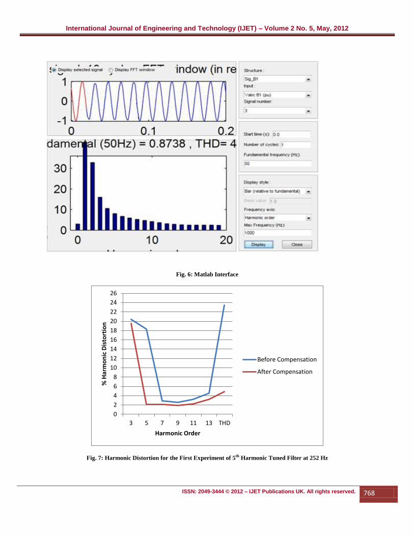
The interface of the Matlab/Simulink is shown in Figure 6. The
upper path of the window shows the voltage waveform of the
signal and the lower portion shows the THD of the system. The
simulation is done on the Simulink window and results are
obtained from the FFT window. The simulation time was ten
minutes.
Results of simulation for the 5th
harmonic tuned filter at
frequencies of 252 Hz, 256 Hz and 247 Hz are as shown in
Figures 7, 8, and 9 respectively. Figures 10, 11 and 12
correspond to results for the 7th
harmonic filter at 356 Hz, 364
Hz and 348 Hz respectively.
Three-Phase Source
A
B
C
Three-Phase Shunt Passive Harmonic Filter
A B C
Rectifier
A
B
C
+
-
Load
International Journal of Engineering and Technology (IJET) – Volume 2 No. 5, May, 2012
ISSN: 2049-3444 © 2012 – IJET Publications UK. All rights reserved. 768
Fig. 6: Matlab Interface
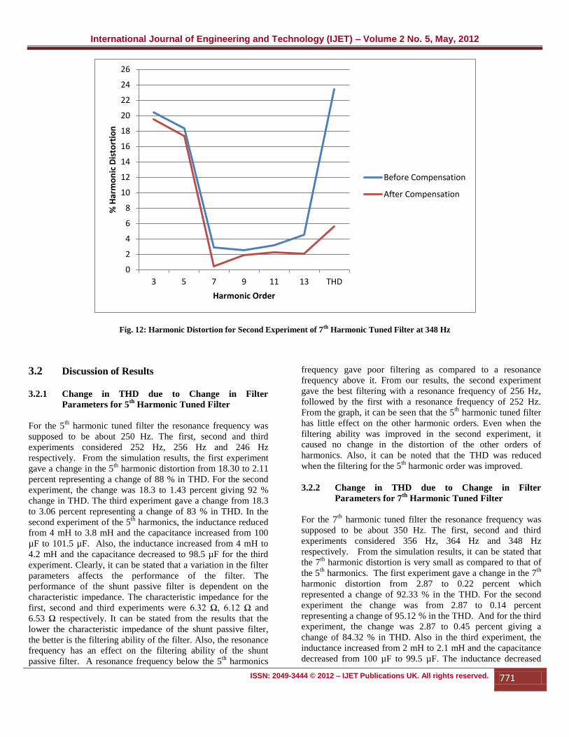
Fig. 7: Harmonic Distortion for the First Experiment of 5th Harmonic Tuned Filter at 252 Hz
0
2
4
6
8
10
12
14
16
18
20
22
24
26
3 5 7 9 11 13 THD
% H
arm
on
ic D
isto
rtio
n
Harmonic Order
Before Compensation
After Compensation

International Journal of Engineering and Technology (IJET) – Volume 2 No. 5, May, 2012
ISSN: 2049-3444 © 2012 – IJET Publications UK. All rights reserved. 769
Fig. 8: Harmonic Distortion for the Second Experiment of 5th Harmonic Tuned Filter at 256 Hz
Fig. 9: Harmonic Distortion for the Third Experiment of 5th Harmonic Tuned Filter at 247 Hz
0
2
4
6
8
10
12
14
16
18
20
22
24
26
3 5 7 9 11 13 THD
% H
arm
on
ic D
isto
rtio
n
Harmonic Order
Before Compensation
After Compensation
0
2
4
6
8
10
12
14
16
18
20
22
24
26
3 5 7 9 11 13 THD
% H
arm
on
ic D
isto
rtio
n
Harmonic Order
Before Compensation
After Compensation

International Journal of Engineering and Technology (IJET) – Volume 2 No. 5, May, 2012
ISSN: 2049-3444 © 2012 – IJET Publications UK. All rights reserved. 770
Fig. 10: Harmonic Distortion for the First Experiment of 7th Harmonic Tuned Filter at 356 Hz
Fig. 11: Harmonic Distortion for the Second Experiment of 7th Harmonic Tuned Filter at 364 Hz
0
2
4
6
8
10
12
14
16
18
20
22
24
26
3 5 7 9 11 13 THD
% H
arm
on
ic D
isto
rtio
n
Harmonic Order
Before Compensation
After Compensation
0
2
4
6
8
10
12
14
16
18
20
22
24
26
3 5 7 9 11 13 THD
% H
arm
on
ic D
isto
rtio
n
Harmonic Order
Before Compensation
After Compensation
International Journal of Engineering and Technology (IJET) – Volume 2 No. 5, May, 2012
ISSN: 2049-3444 © 2012 – IJET Publications UK. All rights reserved. 771
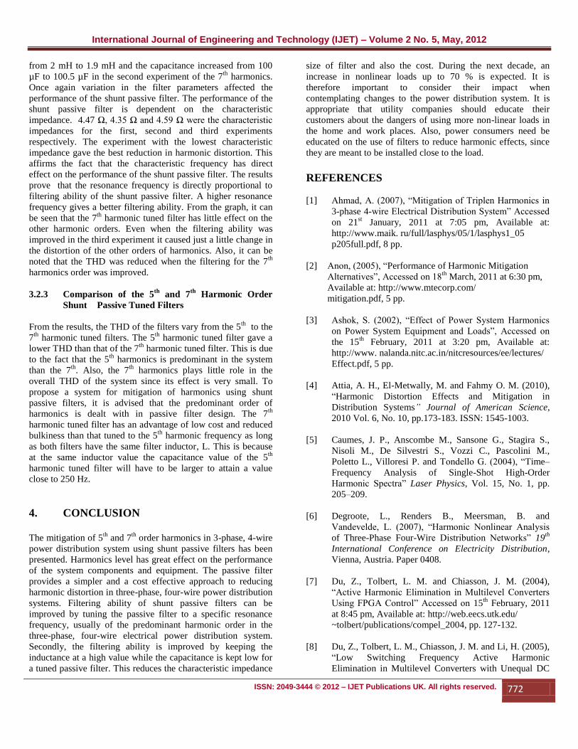
Fig. 12: Harmonic Distortion for Second Experiment of 7th Harmonic Tuned Filter at 348 Hz
3.2 Discussion of Results
3.2.1 Change in THD due to Change in Filter
Parameters for 5th
Harmonic Tuned Filter
For the 5th
harmonic tuned filter the resonance frequency was
supposed to be about 250 Hz. The first, second and third
experiments considered 252 Hz, 256 Hz and 246 Hz
respectively. From the simulation results, the first experiment
gave a change in the 5th
harmonic distortion from 18.30 to 2.11
percent representing a change of 88 % in THD. For the second
experiment, the change was 18.3 to 1.43 percent giving 92 %
change in THD. The third experiment gave a change from 18.3
to 3.06 percent representing a change of 83 % in THD. In the
second experiment of the 5th
harmonics, the inductance reduced
from 4 mH to 3.8 mH and the capacitance increased from 100
µF to 101.5 µF. Also, the inductance increased from 4 mH to
4.2 mH and the capacitance decreased to 98.5 µF for the third
experiment. Clearly, it can be stated that a variation in the filter
parameters affects the performance of the filter. The
performance of the shunt passive filter is dependent on the
characteristic impedance. The characteristic impedance for the
first, second and third experiments were 6.32 Ω, 6.12 Ω and
6.53 Ω respectively. It can be stated from the results that the
lower the characteristic impedance of the shunt passive filter,
the better is the filtering ability of the filter. Also, the resonance
frequency has an effect on the filtering ability of the shunt
passive filter. A resonance frequency below the 5th
harmonics
frequency gave poor filtering as compared to a resonance
frequency above it. From our results, the second experiment
gave the best filtering with a resonance frequency of 256 Hz,
followed by the first with a resonance frequency of 252 Hz.
From the graph, it can be seen that the 5th
harmonic tuned filter
has little effect on the other harmonic orders. Even when the
filtering ability was improved in the second experiment, it
caused no change in the distortion of the other orders of
harmonics. Also, it can be noted that the THD was reduced
when the filtering for the 5th
harmonic order was improved.
3.2.2 Change in THD due to Change in Filter
Parameters for 7th
Harmonic Tuned Filter
For the 7th
harmonic tuned filter the resonance frequency was
supposed to be about 350 Hz. The first, second and third
experiments considered 356 Hz, 364 Hz and 348 Hz
respectively. From the simulation results, it can be stated that
the 7th
harmonic distortion is very small as compared to that of
the 5th
harmonics. The first experiment gave a change in the 7th
harmonic distortion from 2.87 to 0.22 percent which
represented a change of 92.33 % in the THD. For the second
experiment the change was from 2.87 to 0.14 percent
representing a change of 95.12 % in the THD. And for the third
experiment, the change was 2.87 to 0.45 percent giving a
change of 84.32 % in THD. Also in the third experiment, the
inductance increased from 2 mH to 2.1 mH and the capacitance
decreased from 100 µF to 99.5 µF. The inductance decreased
0
2
4
6
8
10
12
14
16
18
20
22
24
26
3 5 7 9 11 13 THD
% H
arm
on
ic D
isto
rtio
n
Harmonic Order
Before Compensation
After Compensation
International Journal of Engineering and Technology (IJET) – Volume 2 No. 5, May, 2012
ISSN: 2049-3444 © 2012 – IJET Publications UK. All rights reserved. 772
from 2 mH to 1.9 mH and the capacitance increased from 100
µF to 100.5 µF in the second experiment of the 7th
harmonics.
Once again variation in the filter parameters affected the
performance of the shunt passive filter. The performance of the
shunt passive filter is dependent on the characteristic
impedance. 4.47 Ω, 4.35 Ω and 4.59 Ω were the characteristic
impedances for the first, second and third experiments
respectively. The experiment with the lowest characteristic
impedance gave the best reduction in harmonic distortion. This
affirms the fact that the characteristic frequency has direct
effect on the performance of the shunt passive filter. The results
prove that the resonance frequency is directly proportional to
filtering ability of the shunt passive filter. A higher resonance
frequency gives a better filtering ability. From the graph, it can
be seen that the 7th
harmonic tuned filter has little effect on the
other harmonic orders. Even when the filtering ability was
improved in the third experiment it caused just a little change in
the distortion of the other orders of harmonics. Also, it can be
noted that the THD was reduced when the filtering for the 7th
harmonics order was improved.
3.2.3 Comparison of the 5th
and 7th
Harmonic Order
Shunt Passive Tuned Filters
From the results, the THD of the filters vary from the 5th
to the
7th
harmonic tuned filters. The 5th
harmonic tuned filter gave a
lower THD than that of the 7th
harmonic tuned filter. This is due
to the fact that the 5th
harmonics is predominant in the system
than the 7th
. Also, the 7th
harmonics plays little role in the
overall THD of the system since its effect is very small. To
propose a system for mitigation of harmonics using shunt
passive filters, it is advised that the predominant order of
harmonics is dealt with in passive filter design. The 7th
harmonic tuned filter has an advantage of low cost and reduced
bulkiness than that tuned to the 5th
harmonic frequency as long
as both filters have the same filter inductor, L. This is because
at the same inductor value the capacitance value of the 5th
harmonic tuned filter will have to be larger to attain a value
close to 250 Hz.
4. CONCLUSION
The mitigation of 5
th and 7
th order harmonics in 3-phase, 4-wire
power distribution system using shunt passive filters has been
presented. Harmonics level has great effect on the performance
of the system components and equipment. The passive filter
provides a simpler and a cost effective approach to reducing
harmonic distortion in three-phase, four-wire power distribution
systems. Filtering ability of shunt passive filters can be
improved by tuning the passive filter to a specific resonance
frequency, usually of the predominant harmonic order in the
three-phase, four-wire electrical power distribution system.
Secondly, the filtering ability is improved by keeping the
inductance at a high value while the capacitance is kept low for
a tuned passive filter. This reduces the characteristic impedance
size of filter and also the cost. During the next decade, an
increase in nonlinear loads up to 70 % is expected. It is
therefore important to consider their impact when
contemplating changes to the power distribution system. It is
appropriate that utility companies should educate their
customers about the dangers of using more non-linear loads in
the home and work places. Also, power consumers need be
educated on the use of filters to reduce harmonic effects, since
they are meant to be installed close to the load.
REFERENCES
[1] Ahmad, A. (2007), “Mitigation of Triplen Harmonics in
3-phase 4-wire Electrical Distribution System” Accessed
on 21st January, 2011 at 7:05 pm, Available at:
http://www.maik. ru/full/lasphys/05/1/lasphys1_05
p205full.pdf, 8 pp.
[2] Anon, (2005), “Performance of Harmonic Mitigation
Alternatives”, Accessed on 18th
March, 2011 at 6:30 pm,
Available at: http://www.mtecorp.com/
mitigation.pdf, 5 pp.
[3] Ashok, S. (2002), “Effect of Power System Harmonics
on Power System Equipment and Loads”, Accessed on
the 15th
February, 2011 at 3:20 pm, Available at:
http://www. nalanda.nitc.ac.in/nitcresources/ee/lectures/
Effect.pdf, 5 pp.
[4] Attia, A. H., El-Metwally, M. and Fahmy O. M. (2010),
“Harmonic Distortion Effects and Mitigation in
Distribution Systems” Journal of American Science,
2010 Vol. 6, No. 10, pp.173-183. ISSN: 1545-1003.
[5] Caumes, J. P., Anscombe M., Sansone G., Stagira S.,
Nisoli M., De Silvestri S., Vozzi C., Pascolini M.,
Poletto L., Villoresi P. and Tondello G. (2004), “Time–
Frequency Analysis of Single-Shot High-Order
Harmonic Spectra” Laser Physics, Vol. 15, No. 1, pp.
205–209.
[6] Degroote, L., Renders B., Meersman, B. and
Vandevelde, L. (2007), “Harmonic Nonlinear Analysis
of Three-Phase Four-Wire Distribution Networks” 19th
International Conference on Electricity Distribution, Vienna, Austria. Paper 0408.
[7] Du, Z., Tolbert, L. M. and Chiasson, J. M. (2004),
“Active Harmonic Elimination in Multilevel Converters
Using FPGA Control” Accessed on 15th
February, 2011
at 8:45 pm, Available at: http://web.eecs.utk.edu/
~tolbert/publications/compel_2004, pp. 127-132.
[8] Du, Z., Tolbert, L. M., Chiasson, J. M. and Li, H. (2005),
“Low Switching Frequency Active Harmonic
Elimination in Multilevel Converters with Unequal DC
International Journal of Engineering and Technology (IJET) – Volume 2 No. 5, May, 2012
ISSN: 2049-3444 © 2012 – IJET Publications UK. All rights reserved. 773
Voltages”, Accessed on 25th
March, 2011 at 10:20 pm,
Available at: http://ieeexplore.ieee.org/stamp/stamp.js
p?arnumber=01518297, 8 pp.
[9] Du, Z., Tolbert, L. M. and Chiasson, J. N. (2006),
“Active Harmonic Elimination for Multilevel
Converters”, IEEE Transactions on Power Electronics,
Vol. 21, No. 2, pp. 459-469.
[10] Du, Z., Tolbert, L. M., Chiasson, J. N. and Ozpineci, B.
(2008), “Reduced Switching-Frequency Active
Harmonic Elimination for Multilevel Converters” IEEE
Transactions on Industrial Electronics, Vol. 55, No. 4,
pp. 1761-1770.
[11] Ghiasi, M., Rashtchi, V. and Hoseini, H., (2002),
“Optimum Location and Sizing of Passive Filters in
Distribution Networks using Genetic Algorithm”
Assessed on 25th
March, 2011 at 10:20 pm, Available at: http://eeeic.org/proc/papers/13.pdf, 6 pp.
[12] Huang, Q. (1997), “Harmonic Reduction in a Single-
Switch Three-Phase Boost Rectifier with Harmonic-
Injected PWM”, MSc Thesis, Virginia Polytechnic
Institute and State University, USA, Accesed on the 21st
January, 2011 at 8:00 pm, Available at:
http//citeseerx.Ist.psu .edu/viewdoc/download?doi=
10.1.1.9.9058&rep, 89 pp.
[13] Jayasinghe, N. R., Lucas, J. R. and Perera, K. B. I. M.
(2003), “Power System Harmonic Effects on Distribution
Transformers and New Design Considerations for K-
Factor Transformers”, IEE Sri Lanka Annual Sessions –
September 2003.
[14] Kallianpur, S. (2008), “Harmonic Reduction Methods”,
Accessed on 18th
March, 2011 at 9:00 am, Available at:
www.pacetoday.com.au/news/harmonic-reduction-
methods, 3 pp.
[15] Key, T. and Lai, J. (2001), “Costs and Benefits of
Harmonic Current Reduction for Switch Mode Power
Supplies in a Commercial Office Building”, Accessed on
15th
February, 2011 at 3:20 pm, Available at:
http://www.activeharmonicfilters.com/Contrac tors /pcs-
costsandbenefitsofharmoniccurrentreduction.pdf, 8pp.
[16] Mahalekshim T. (2010), “Current Harmonic
Compensation and Power Factor Improvement by Hybrid
Shunt Active Power Filter”, International Journal of
Computer Applications, Vol. 4, No.3, pp. 9-13.
[17] Mansoor, Han, Y., Yao, G., Li-Dan, Z. and Chen, C.
(2007), “Harmonic Mitigation of Residential Distribution
System using a Novel Hybrid Active Power Filter”,
WSEAS Transactions on Power Systems, Vol. 2, No.12,
pp. 255-260. ISSN: 1790-5060.
[18] Mindykowski, J., Tarasiuk, T. and Rupnik, P. (2007),
“Problems of Passive Filters Application in Systems with
Varying Frequency”, 9th
International Conference on
Electrical Power and Utilization. Barcelona, Spain. Vol.
11, No. 9, 4 pp.
[19] Morán, L. A., Juan, W., Dixon, J. W., Espinoza, J. R. and
Wallace, R. R. (2007), “Using Active Power Filters to
Improve Power Quality”, Accessed on 11th
March, 2011
at 11:05 am, Available at: http://web.ing.puc.cl/
~power/paperspdf/dixon/37a.pdf, 12 pp.
[20] Omar, R., Ahmad, A. and Sulaiman, M. (2010), “Triplen
Harmonics Mitigation in 3-Phase Four-Wire Electrical
Distribution System using Wye-Zig-Zag Transformers”,
Journal of Emerging Trends in Engineering and Applied
Sciences (JETEAS) Vol.1, No.1, pp. 72-78.
[21] Ortmeyer, T. H. and Hiyama, T. (2000) “Distribution
System Harmonic Filter Planning”, Accessed on 10th
March, 2011 at 2:45 pm, Available at:
http://www.calvin.edu/~pribeiro/IEEE/ieee_cd/chapter/
pdffiles, 7 pp.
[22] Pairoj, P. and Somyot, K. (2010), “Harmonic Reduction
Technique in PWM AC Voltage Controller using Particle
Swarm Optimization and Artificial Neural Network”,
Proceedings of the International Multi Conference of
Engineers and Computer Scientists, 2010, Vol. 2,
IMECS 2010, Hong Kong, 6 pp.
[23] Piel, J. K. and Carnovale, P. E. D. J. (2004), “Economic
and Electrical Benefits of Harmonic Reduction Methods
in Commercial Facilities”, Accessed on 18th
March,
20011 at 3:15 pm, Available at :
www.eaton.com/Electrical/idcplg?RevisionSelectionMet
hod, 12 pp.
[24] Pinto, J. G., Pregitzer, R., Monteiro, L. F. C., Conto, C.
and Afonso, J. C. (2007), “A Combined Series Active
Filter and Passive Filter for Harmonic Unbalances and
Flicker Compensation”, International Conference on
Power Engineering, Energy and Electrical Drives,
Setubal, Portugal, 12th
-14th
April, 2007, 10 pp.
[25] Ramos, V. A. (2007), “Treating Harmonics in Electrical
Distribution Systems”, Accessed on 15th
February, 2011
at 3:30 pm, Available at: http://www.cpccorp.com/
harmonic. Htm, 5 pp.
[26] Ray, L. and Hapeshis, L (2005), “ Power System
Harmonic Fundamental Considerations: Tips and Tools
for Reducing Harmonic Distortion in Electronic Drive

International Journal of Engineering and Technology (IJET) – Volume 2 No. 5, May, 2012
ISSN: 2049-3444 © 2012 – IJET Publications UK. All rights reserved. 774
Applications” Accessed on 18th
March, 2011 at 7:00 pm,
Available at: http://www.powerlogic .com/
literature/HarmonicConsiderationsDec05.pdf,5 pp.
[27] Ryckaert, W. R. A., Desmet, J. J. M. and Driesen J.
(2004), “The Influence on Harmonic Propagation of the
Resistive Shunt Harmonic Impedance Location along a
Distribution Feeder and the Influence of Distributed
Capacitors”, Accessed on 15th
March, 2011 at 12:30 pm,
Available at: http://www.esat.kuleuven.be/
electa/publications/fulltexts/pub 1263.pdf, 9 pp.
[28] Salam, Z., Cheng, T. P. and Jusoh, A. (2006),
“Harmonics Mitigation using Active Power Filter: A
Technological Review”, Department of Energy
Conversion, Faculty of Electrical Engineering,
University Technology, Malaysia, Vol. 8, No. 2,
pp.17‐26.
[29] Vijayakumar, M. and Eswarlal C. (2009), “Mitigation of
Harmonics in 3-phase Four Wire Distribution System- A
Combined System of Shunt Passive and Series Active
Filters” Proceedings of the International Conference on
Electrical Energy Systems and Power Electronics in
Emerging Economies, Chennai, India, pp. 512-518.
ISBN: 978-93-80043-15-9.