approach to integrate product conceptual design...
TRANSCRIPT

Approach to integrate product conceptual design information into a computer-aided design system
Victor H. Torres, Jose Rfos, Antonio Vizan and Jesus M. Perez
Abstract Commercial computer-aided design systems support the geometric definition of product, but they lack utilities to support initial design stages. Typical tasks such as customer need capture, functional requirement formalization, or design parameter definition are conducted in applications that, for instance, support "quality function deployment" and "failure modes and effects analysis" techniques. Such applications are noninteroperable with the computer-aided design systems, leading to discontinuous design information flows. This study addresses this issue and proposes a method to enhance the integration of design information generated in the early design stages into a commercial computer-aided design system. To demonstrate the feasibility of the approach adopted, a prototype application was developed and two case studies were executed.
Keywords Product information modeling, design information flow, computer-aided integrated design, knowledge-based engineering, product knowledge capture
Introduction
The execution of the design process using computer-aided systems requires a continuous flow of information along the different phases: conceptual, embodiment, and detailed. The literature shows that there is a lack of commercial tools supporting the conceptual design phase, and the systems support mainly the geometric modeling of products (Ameri and Dutta, 2005; Guerra-Zubiaga et a l , 2007; Wang et al., 2002). The reason behind this issue is the nature of the product knowledge during the conceptual phase, which mainly relates to design requirements and constraints (Wang et al., 2002).
Computer-aided design (CAD) tools should also support nongeometric information such as customer needs (CNs), requirements, functions, and constraints (Brunetti and Golob, 2000; Tay and Gu, 2002). The differences in the data structure of the software applications and their development environments are also an issue to integrate product information. Prasad (2000) proposed the concept of intelligent information system (IIS) as the way to pursue, which comprised the integration of the following elements: product lifecycle management (PLM)/CAD systems, knowledge management,
concurrent engineering, and computer-integrated manufacturing (CIM). The IIS concept comprises six levels of techniques, methods, and information enrichment. Level 2 (modeling and analysis tools) comprises techniques such as "quality function deployment" (QFD). Level 3 (predictive tools) comprises techniques such as "failure mode and effects analysis" (FMEA). Level 4 comprises the knowledge-based techniques, where the "Methodology and software tools Oriented to Knowledge-based engineering Applications" (MOKA) can be included.
If the information flow, from customer requirements, functional requirements, product functions, product design parameters (DPs) up to product key characteristics (KCs), could be integrated into a CAD
Department of Mechanical and Manufacturing Engineering, Universidad Politecnica de Madrid, Madrid, Spain
Corresponding author: Jose Rios, Department of Mechanical and Manufacturing Engineering, Universidad Politecnica de Madrid, Jose Gutierrez Abascal 2, 28006 Madrid, Spain. Email: [email protected]

system, then product KCs and product DPs could be traced back to the problem domain information, and they could be used in the development of knowledge-based applications (KBAs) to automate the product geometric definition. With such aim, the integration of information related to the following three techniques into a CAD system is proposed: QFD, axiomatic design (AD), and FMEA, together with product information captured as MOKA forms. The independence axiom and the information axiom proposed by the AD theory are out of scope of the proposed software development. The theoretical and methodological approach and the development framework were presented in the study by Torres et al. (2010). This article focuses on the definition of the information model to support a continuous information flow from conceptual design to detailed design and its implementation into a commercial CAD system. Figure 1 shows the proposed approach.
The next section presents a review of works dealing with product conceptual design information modeling and its integration in software applications. Section "Development methodology to integrate: QFD, AD, FMEA, and MOKA" presents a summary of the adopted methodological approach. Section "IIM" presents the proposed model to integrate the product
conceptual design information. Section "IIM implementation: prototype application" shows the implementation of such model into a prototype development created for a commercial CAD system. Sections "Methodology and case study discussion" and "Conclusions" present discussion and conclusions of this article, respectively.
Review of product conceptual design information modeling
The modeling of product conceptual design information requires considering design techniques that can be used along the conceptual design phase and the information flow from the problem definition phase up to the detailed design phase. Three basic techniques that can be used for that purpose are QFD, AD, and FMEA. The application of these techniques allows connecting customer requirements, functional requirements, product functions, product DPs, product function failures, and product key or critical characteristics, literature exists where the possible integration of such techniques is analyzed. Relevant references can be found in the studies by Prasad (2000) and Torres et al. (2010). Two case studies illustrating the connection of
Design Methodologies
QFD
FMEA
> '
Axiomatic Design (AD)
Mapped into
Illustration
-Product knowledge capture
Functional Product
Structure
CATIA Product
Structure
Constraint
Activity
Rule
Entity
Used to develop
MOKA ICARE Forms
Product
I Part
Feature
in Parameter
Related to
Microsoft Access DBMS
CATIA v5 KBE Environment (VBA-API)
7 Interface to store and retrieve data
Figure I . Top-level view of the proposed approach.
QFD: quality function deployment; FMEA: failure mode and effects analysis; MOKA: Methodology and software tools Oriented to
Knowledge-based engineering Applications; ICARE: Illustrations, Constraints, Activities, Rules, and Entities; DBMS: database management
system; VBA: Visual Basic for Applications; API: application programming interface; KBE: Knowledge Based Engineering.

the three techniques can be found in the studies by Torres et al. (2010) and Zheng et al. (2012).
Since the feasibility of an approach of integrating QFD, AD, and FMEA is shown in the literature, the first issue to analyze is whether information supporting such techniques is part of the product information models, and if so, whether such information was implemented into CAD systems. Tay and Gu (2002) combined product geometric information, in the form of two-dimensional (2D) drawings, with a database where AD concepts (functional requirements and DPs) were stored. The nongeometric information was modeled in a database schema that comprised the following entities: products, function, function-constraint, constraint, function-form, input-output, part-assembly, component-feature, feature-type, and component-constraint. The database schema was implemented into a relational database management system, and a link was created to the CAD system to show a 2D drawing representing the product. Ferrer et al. (2010) also proposed the conceptual integration of AD information, derived from the following four domains: customer, functional, physical, and process, within a CAD system, although no real implementation was reported. Zheng et al. (2010) aimed to integrate FMEA with computer-aided product and process development tools. To achieve such integration, they proposed an integrated information model (IIM) of product and process design with process FMEA. The integration of QFD and AD with FMEA was out of scope. The proposed model was structured into five parts, as follows: product card, part information, FMEA Knowledge, Process Information, and Machining Resource. In the part information section, the concepts modeled were as follows: part, feature, feature-face, and Key-Characteristic. The development allowed the designer marking product KC in the geometric model and to define the associated FMEA information. Bohm et al. (2008) developed a data schema to capture non-geometric design information and to create a design repository. The schema was structured into seven information units: artifact related, function related, failure related, physical related, performance related, sensory related, and media related. Some of the concepts defined in such schema were artifact, customer need, parameter, function-flow, failure, sad failure-data-info. In this case, both the integration of design information within a CAD system and continuous design information flow comprising QFD, AD, and FMEA were not addressed. Chang et al. (2008) focused on functional modeling of products by means of diagrams created using M-IDEF0 (a modified IDEF0 notation). The integration of QFD, AD, and FMEA concepts was out of scope. The graphical notation was supported by the definition of its corresponding ontology, the defined classes were function, flow, component, sad function-group. Initially proposed
by Gero (1990), the function-behavior-structure (FBS) model is one of the main approaches to represent product conceptual knowledge. Christophe et al. (2010) followed the FBS approach and used OMG Systems Modeling Language (OMG SysML) diagrams to represent product conceptual knowledge. SysML provides three main groups of diagrams: requirements, behavior, and structure. The diagrams to represent behavior are activity, sequence, state machine, and use. The diagrams to represent structure are block definition, internal block, parametric, and package. SysML provides the semantic for the different concepts supported by the language. For instance, the concept requirement is modeled with the following attributes: id, text, derived, derivedFrom, satisfiedBy, refinedBy, tracedTo, verifiedBy, and master (OMG, 2010).
As it was shown so far, different works aimed to integrate product conceptual nongeometric information into computer-aided applications. However, none of them proposed an information model or reported an implementation, where concepts from QFD, AD, and FMEA were integrated with the aim of achieving a continuous product design information flow.
The second issue to analyze is the representation of product knowledge to be used in the development of KBAs. KBAs are created to automate the design (the geometric modeling) of products and components and to guarantee that the obtained design is correct. MOKA methodology addresses this issue. MOKA provides the following five knowledge objects: Illustrations, Constraints, Activities, Rules, and Entities (ICARE). An Entity can be a Functional_Entity or a Structural_Entity {Part, Product, Assembly, and Feature). A Design_ Process is modeled by Activities. These objects are modeled in two ways, namely, "informal" way consists in forms to be filled by the designer and "formal" way consists in classes to be implemented in a software application to support the development of an intended KBA. Ammar-Khodja et al. (2008) used MOKA to support KBA development and to reuse of design knowledge. They proposed the enrichment of the MOKA objects, by including the concepts of resource, to consider tools and machines used in manufacturing processes, and function, to define design reasoning activities. Skarka (2007) implemented MOKA classes into Protege, used as repository of product knowledge, and used a commercial CAD system (CATIA v5) to create a KBA application to automate the product geometrical design.
The third issue to review is how commercial CAD applications integrate nongeometric product information. For instance, in CATIA V5, the product functional definition (PFD) module allows defining functional relationships among product components. It uses the following three concepts: subsystem, functional

object, and action. A product function optimization (PFO) module can be used to create a combined functional and physical view of the product and an interaction matrix of the different components. Such module is based on the theory of inventive problem solving (TRIZ) to help in the search for possible physical principles to improve the design. A systematic process to design a robot for biomass processing and the use of CATIA PFO for functional analysis optimization is reported by Starcevic et al. (2010). Similar functionalities can also be found in other commercial systems, for instance, NX Nastran Optimization and PTC Creo Behavioral Modeling Extension.
From the reviewed literature, it can be concluded that the integration of product conceptual design information into CAD systems is being addressed in several ways by different researchers. The product information models partially comprise the information used at the conceptual phase, but a continuous information flow based on integrating concepts from the three techniques, QFD, AD, and FMEA, is not reported. In this sense, this study can be seen as a first contribution to pursue such integration. The main contributions of this study are the proposal of an information model integrating concepts from the three techniques and the implementation of such model into a prototype application within a commercial CAD system.
Development methodology to integrate QFD, AD, FMEA, and MOKA
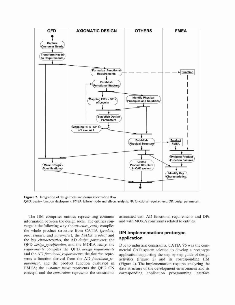
The objective of integrating the design techniques is to define the information flow that supports the design tasks in a chronological way along the design process, identifying the information inputs and outputs. The proposed methodology is based on an information flow (Figure 2) generated when executing the following steps (Torres et al., 2010):
• Use QFD to capture customer needs (CNs) and formalize them into requirements.
• Based on the AD theory, select the functional requirements (FRs), decompose them, and map them into DPs, creating the structural decomposition.
• Use FMEA to identify the DPs that are critical (KCs) to the product functionality by analyzing failures and effects.
• Along the process and in parallel to the three prior steps, MOKA ICARE forms are used to document relevant product information related to CNs, FRs, DPs, KCs, rules, and constraints. In addition, such information can then be used to develop KBAs to automate the product geometric design.
A first case study related to a clutch system was conducted to evaluate the suitability of the proposed conceptual approach (Torres et al., 2010). Ultimately, the objective was the implementation of such approach into a commercial CAD system. The implementation was carried out by means of a step-by-step tool to guide the designer along the different tasks. A second case study for an aircraft Y-bolt component was carried out to validate both the conceptual approach and its implementation (Zheng et al., 2012). The implementation required to define a mapping between the data structure supporting the information flow and the data structure of the CAD system. The product tree structure of the commercial CAD system supports the concepts: product, part, feature and parameter, and the hierarchical structural decomposition of DPs needed to be mapped into that structure. Figure 2 shows the design tools used in the methodological approach and its corresponding information flow.
Integrated Information Model (MM)
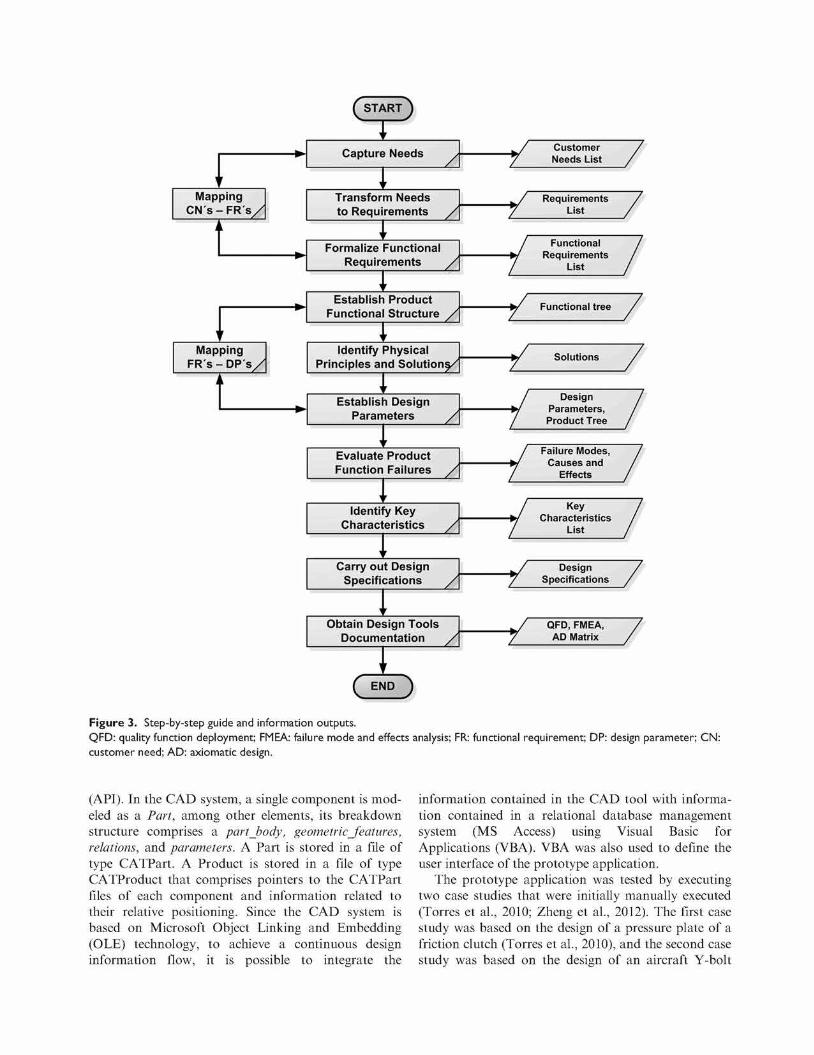
Prior to define the information model, a step-by-step guide of the tasks to be executed by the designer was defined. It shows the tasks to capture and define product information and its flow along the design process. Using UML notation, a use case was created to define the link between the design tools and the events flow along the design process. A UML activity diagram was also created to define inputs and outputs of each design tool (Figures 2 and 3).
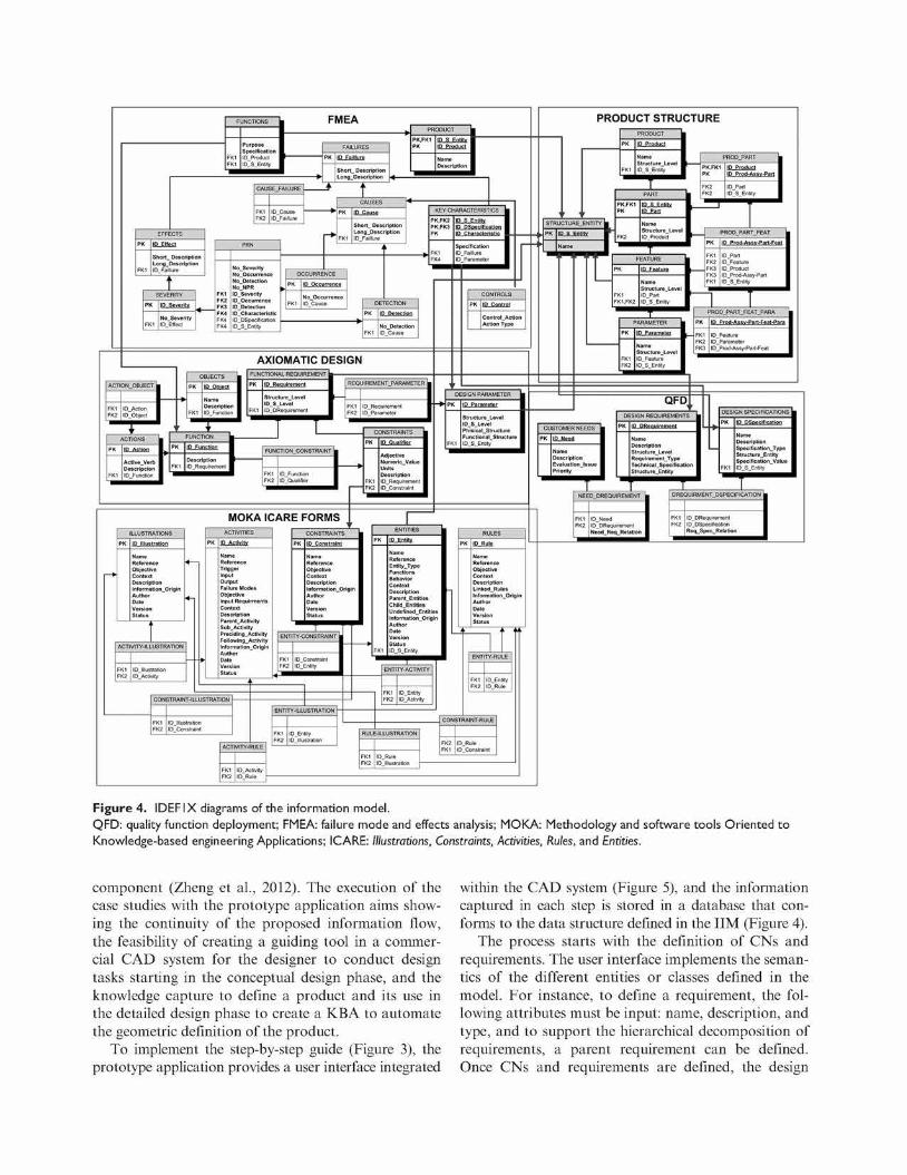
The documentation of product information by means of the MOKA ICARE forms runs in parallel with the execution of the different steps of the product design process. From the analysis of QFD, AD, FMEA, product breakdown structure, and MOKA, five units of information were defined. Each of them defines a static view or data schema: entities, attributes of each entity, and relationships between entities. The IDEF1X technique was used for their representation (Figure 4). From the initial five data schemas, an IIM was derived. The IIM allows keeping a continuous flow of information (Figure 3) by including the fundamental entities of each technique and their relationships. If needed, additional entities to fully support QFD and FMEA could be incorporated into the implementation. The IIM contains the following main entities (shaded boxes in Figure 4): product, part, feature, parameter, structure_entity, design _p ar ameter, functional Requirement, function, constraint, key^characteristics, entity, FMEA_product, customerjieeds, requirements, and design_specifications.
QFD
T f Capture A VCustomer Need^/
1 /Transform Needs\ \ t o Requirements/
' -\
/Make Design^
Is, deifications.
AXIOMATIC DESIGN
/Formalize Functional V Requirements J~
1 / " Establish "\ \£unctional Stucture
" /Mapping FR's - DP'sN V of Level n J
+ \
/Establish Design V Parameters J
/Mapping FR's - DP's\ V̂ of Level n+1 J*
OTHERS
f Identify Physical ^ VPrinciples and Solutions^
___. ' ^ \ ^ ( Establish "\ VPhysical Structure/
^ ^ \ f Create 7, ^ ~ 1 Product Structure I \ i n CAD systern/
— i ' -
i
FMEA
— — >• Function
— * • Product FMEA
* • 7
/Evaluate Product
Q
vi-uncuon i-anuresy
k. "
1 dentify Key•N aracteristics,
Figure 2. Integration of design tools and design information flow.
QFD: quality function deployment; FMEA: failure mode and effects analysis; FR: functional requirement; DP: design parameter.
The IIM comprises entities representing common information between the design tools. The entities converge in the following way: the structure_entity compiles the whole product structure from CATIA {product, part, feature, and parameter), the FMEA_product and the key characteristics, the AD design_parameter, the QFD design_specification, and the MOKA entity; the requirements compiles the QFD design_requirements and the AD functionalRequirements; the function represents a function derived from the AD functional Requirement, and the product function evaluated in FMEA; the customerjieeds represents the QFD CN concept; and the constraints represents the constraints
associated with AD functional requirements and DPs and with MOKA constraints related to entities.
IIM implementation: prototype application
Due to industrial constraints, CATIA V5 was the commercial CAD system selected to develop a prototype application supporting the step-by-step guide of design activities (Figure 2) and its corresponding IIM (Figure 4). The implementation requires analyzing the data structure of the development environment and its corresponding application programming interface
w
Mapping C N ' s - F R ' s /
i i
i ' Mapping
FR's - D P ' s /
i i
CSTART}
1 Capture Needs y
'' Transform Needs to Requirements /*
1 Formalize Functional
Requirements /
\' Establish Product
Functional Structure /
'' Identify Physical
Principles and Solutions/
'' Establish Design
Parameters /
'' Evaluate Product Function Failures /
' ' Identify Key
Characteristics /
* ' Carry out Design
Specifications /
i ' Obtain Design Tools
Documentation /
\
CE ' ID )
,J L_ ,_J z _
J ? tr *L_ tr *L_ J 1
\ J ' L_ J !_
, j 1L_ , A
L
Customer / Needs List /
Requirements / List /
•- •• • / Functional /
Requirements / List /
r» / Design /
Product Tree /
Failure Modes, / Causes and /
Effects /
„ 1 Key /
List /
' Design /
Specifications /
QFD, FMEA, / AD Matrix /
Figure 3. Step-by-step guide and information outputs. QFD: quality function deployment; FMEA: failure mode and effects analysis; FR: functional requirement; DP: design parameter; CN: customer need; AD: axiomatic design.
(API). In the CAD system, a single component is modeled as a Part, among other elements, its breakdown structure comprises a part_body, geometricJ'eatures, relations, and parameters. A Part is stored in a file of type CATPart. A Product is stored in a file of type CATProduct that comprises pointers to the CATPart files of each component and information related to their relative positioning. Since the CAD system is based on Microsoft Object Linking and Embedding (OLE) technology, to achieve a continuous design information flow, it is possible to integrate the
information contained in the CAD tool with information contained in a relational database management system (MS Access) using Visual Basic for Applications (VBA). VBA was also used to define the user interface of the prototype application.
The prototype application was tested by executing two case studies that were initially manually executed (Torres et al., 2010; Zheng et al., 2012). The first case study was based on the design of a pressure plate of a friction clutch (Torres et al., 2010), and the second case study was based on the design of an aircraft Y-bolt
FUNCTIONS
Purpose Specificatior ID_Product ID_S_Entity
FMEA
FAILURES
ID Falllure
CAUSE_FAILURE
Short_ Description Long_Description ID_Faillute
SEVERITY
; ID Severity
No_ Occurrence
ID_Severity ©Occurrence ID_D election ID Characteristic I D_D Specification ID_S_Entity
Short Descriptioi LongDescription IO_Fa ill Lire
OCCURRENCE
KEY CHARACTERISTICS
ID_DSpeciiication
Specification ID_Faillure IDPara meter
AXIOMATIC DESIGN
ACTION_OBJECT
AcIive_Verb Descripcion ID_Function
Descriptio ID_Functioi
FUNCTIONAL REQUIREMENT
lP_Requirement
Structure_Level ID_S_Level I D_D Requirement
REQUIREMENT_PARAMETER
FUNCTION_CONSTRAINT
MOKA ICARE FORMS ILLUSTRATIONS
PK ID Illustration
Objective Context Description I nformatio nOrig i r Author Date Version Status
ACTIVITY-ILLUSTRATION
PK ID Activity
Reference Trigger
Output Failure Modes Objective Input Requirments Content Description Parent_Activity Sub_Activity Preciding_Activity F ollowing_ Acti v ity InformationOrigin Author Date Version Status
CONSTRAINTS
Adjective Numeric, Value Units Description IDRequirement ID_Constraini
CONTROLS
PK ID Control
Co ntrol_ Action Action Type
DESIGN PARAMETER
St rocture_ Level ID_S_Level PhisicalStructure F u n ct iona l_Stru ct u re ID_S_Entily
CONSTRAINTS
PK ID Constraint
Reference Objective Context
InformationOrigir Author
ENTITY-CONSTRAINT
CONSTRAINT-ILLUSTRATION
ACTIVITY-RULE
ENTITY-ILLUSTRATION
Reference Entity_Type
Context Description ParentEntities Child_Entities Undefined_Entitie: InformationOrigir
Date Version Status ID_S_Entity
ENTITY-ACTIVITY
RULE-ILLUSTRATION
I D_l I lustration
Reference Objective Context
Linked Rules InformationOrigin Author
Version Status
ENTITY-RULE
CONSTRAINT-RULE
PRODUCT STRUCTURE
STRUCTURE_ENTITY L
PK ID S Entity P "
Name I
ID Prod-Assy-Part
Structure Level ID_Part ID_S_Entity
PROD_PART_FEAT
PK
FK1 FK? FK3 FK3 I-K1
ID Part ID Feature ID Product ID Prod-Assy-Part ID_S_Entity
Structure_Level ID_Feature ID_S_ Entity
PROD_PART_FEAT_PARA
PK ID Prod-Assv-Part-Feat-Para
FK1 ID Feature FK2 IDParameter FK3 ID_Prod-Assy-Part-Feat
QFD
CUSTOMER NEEDS
PK ID Need
Description Evaluationlssue Priority
DESIGN R E Q U I R E M E N T S
ID D R e o u i r e m e n t
S t r u c t u r e _ L e v e l R e q u i r e m e n t _ T y p e T e c h n i c a I S p ec i f i c a 11 o n S t r u c t u re_En t i t y
DESIGN SPECIFICATIONS
ID DSpec i f i ca t i on
D e s c r i p t i o n S pec i f i ca t i on_Ty pe S t r u c t u r e E n t i t y
Spec t f l ca t l on_Va lue ID_S_Enti ty
N E E D _ D R E Q U I R E M E N T DREQUIRMENT_DSPECIF ICAT ION
ID_DRequi rement I D_DSpecif l cation R e q S pe c_Re lat io n
Figure 4. IDEFIX diagrams of the information model. QFD: quality function deployment; FMEA: failure mode and effects analysis; MOKA: Methodology and software tools Oriented to Knowledge-based engineering Applications; ICARE: Illustrations, Constraints, Activities, Rules, and Entities.
component (Zheng et al., 2012). The execution of the case studies with the prototype application aims showing the continuity of the proposed information flow, the feasibility of creating a guiding tool in a commercial CAD system for the designer to conduct design tasks starting in the conceptual design phase, and the knowledge capture to define a product and its use in the detailed design phase to create a KBA to automate the geometric definition of the product.
To implement the step-by-step guide (Figure 3), the prototype application provides a user interface integrated
within the CAD system (Figure 5), and the information captured in each step is stored in a database that conforms to the data structure defined in the IIM (Figure 4).
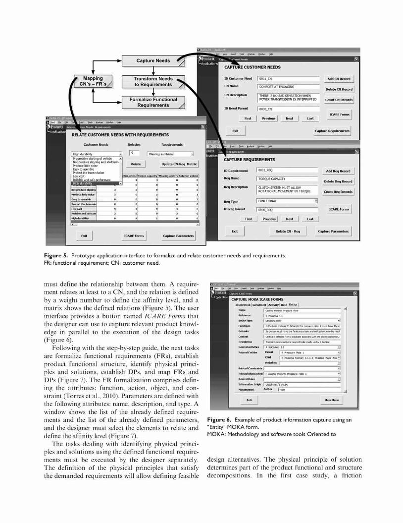
The process starts with the definition of CNs and requirements. The user interface implements the semantics of the different entities or classes defined in the model. For instance, to define a requirement, the following attributes must be input: name, description, and type, and to support the hierarchical decomposition of requirements, a parent requirement can be defined. Once CNs and requirements are defined, the design
Has
RELATE CUSTOMER NEEDS WITH REQUIREMENTS
Capture Needs
I Sew Insert Toe* An^re £ridow Help
Transform Needs to Requirements
I Formalize Functional
Requirements
| Wearing and fricion Progressive starting of vehicle Not produce slipping and shidderim Produce little noise Easy to asemble Protect the transmission Low cost Reliable and safe
WljjiKitclSHI Not produce slipping
Produce ittte nose
r.isy to asemble
Protect the transmis
Low cost
Reliable and safe pe
High durability
serformace ^ ^ H J
3J 3
0
°l 9I 3J o|
Relate Update CN-Req Matrix
rtJonof erte
l
0
3
0
0
0
3
9
9
Torque capacity
3
0
9
3
0
0
9
9
1
Wearing and fri.
0
0
9
0
0
0
3
3
9
Rotation volume
0
0
0
3
3
0
3
0
0
Capture Parameters
Took Analyze Window Help
CAPTURE CUST
ID Customer Need
CNName
CN Description
ID Need Parent
First
. Exit
DMER NEEDS
| 0001.CN
1 COMFORT AT ENGAGING
1 THERE IS NO BAD SENSATION WHEN POWER TRANSMISSION IS INTERRUPTED
| 0000_CN|
| Previous | Next | Last
Add CN Record
Delete CN Record
Count CN Records
ICARE Forms
Capture Requirements
CAPTURE REQUIREMENTS
ID Requirement | 0001_REQ
| TORQUE CAPACITY
CLUTCH SYSTEM MUST ALLOW ROTATIONAL MOVEMENT BY TORQUE
Add Req Record
Delete Req Record
Count Req Records
| FUNCTIONAL
| 0000_REQ
Relate CN - Req Capture Parameters
Figure 5. Prototype application interface to formalize and relate customer needs and requirements.
FR: functional requirement; C N : customer need.
must define the relationship between them. A requirement relates at least to a CN, and the relation is defined by a weight number to define the affinity level, and a matrix shows the defined relations (Figure 5). The user interface provides a button named ICARE Forms that the designer can use to capture relevant product knowledge in parallel to the execution of the design tasks (Figure 6).
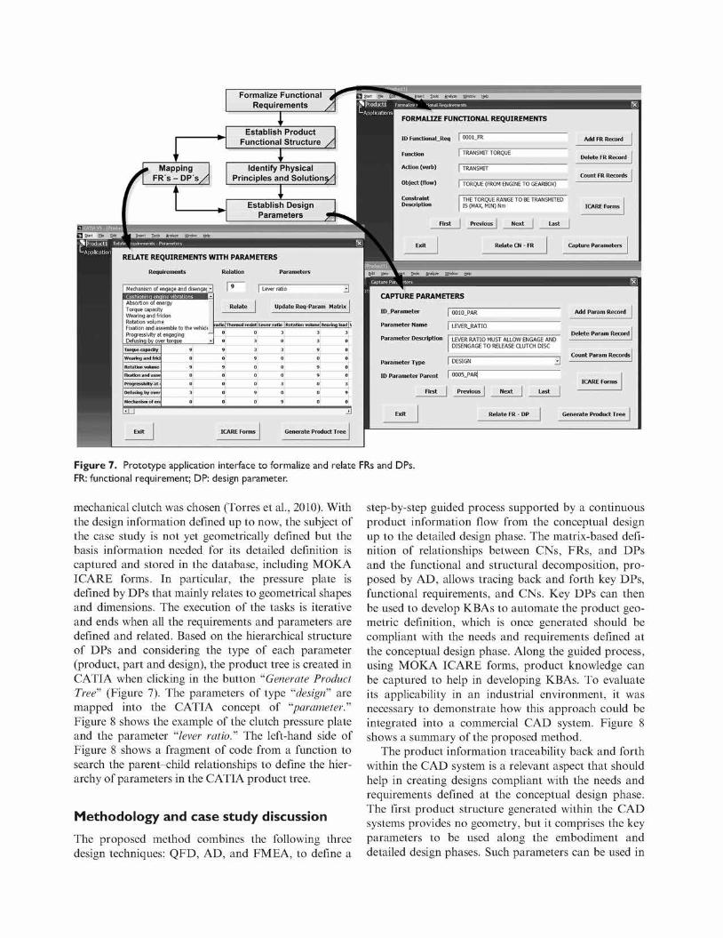
Following with the step-by-step guide, the next tasks are formalize functional requirements (FRs), establish product functional structure, identify physical principles and solutions, establish DPs, and map FRs and DPs (Figure 7). The FR formalization comprises defining the attributes: function, action, object, and constraint (Torres et al., 2010). Parameters are defined with the following attributes: name, description, and type. A window shows the list of the already defined requirements and the list of the already defined parameters, and the designer must select the elements to relate and define the affinity level (Figure 7).
The tasks dealing with identifying physical principles and solutions using the defined functional requirements must be executed by the designer separately. The definition of the physical principles that satisfy the demanded requirements will allow defining feasible
View Insert Xools Analyw Wjnd
CAPTURE MOKA ICARE FORMS I l lustration | Constraint | Activity j Rule Entity
Name
Reference
Entity Type
Functions
Behavior
Context
Description
Related Activities
Related Entities
Plate
E PCastlna 1
Is the base material to fabricate the pressure plate. It must have the ei
Its desiqn must have the fixation svstem and sefcenterria to be mad
Pressure plate castino. is aeometricaiv made up bv 4 bodies:
A SeEasrjna 1.1
Parent
ChM | E Preassure Plate 1
| E PCasCna Fulcrum 1 •
[. E PCasBna Plane Zonij^J
Undefined [""
Related Constraints
Related I hist rations
Related Rules
Information Origin
Management
I CasOna Preform Preassure Plate 1
| Clutch ABC 'sVALEO
Author I VTM
m
Figure 6. Example of product information capture using an
"Entity" M O K A fo rm.
M O K A : Methodology and software tools Or iented to
design alternatives. The physical principle of solution determines part of the product functional and structure decompositions, fn the first case study, a friction
Formalize Functional Requirements
FORMALIZE FUNCTIONAL REQUIREMENTS
RELATE REQUIREMENTS WITH PARAMETERS
Requirements Relation Parameters
Establish Product Functional Structure
Identify Physical Principles and Solutions/
Establish Design Parameters
ID Functional
Function
Action (verb)
Object (flow)
Constraint Description
.Req
First
0001_FR
TRANSMIT TORQUE
TRANSMIT
| TORQUE (FROM ENGINE TO GEARBOX)
THE TORQUE RANGE TO BE TRANSMITED IS (MAX, MIN) Nm
| Previous | Next | Last
Add FR Record
Delete FR Record
Count FR Records
ICARE Forms
Relate CN - FR Capture Parameters
Tools Analyze Wndow hjeb
Mechanism of engage and d jenga< -
Absortion of energy Torque capacity Wearing and fricion Rotation volume Fixation and assemble to the vehicle Progressivity at engaging Defusing by over torque
Torque capacity
Wearing and frici
Rotation volume
Fixation and asse
Progressivity at
Defusing by over
Mechanism of en<
9
0
9
0
0
3
D
[ ^
Relate
Lever ratio
Update Req-Param Matrix
radio | Thermal resist] Lever ratio | Rotation volumel Bearing load|\
0 0 3 3 3
0
9
0
9
0
0
0
0
± T ^
3
3
9
0
0
0
9
0
0
3
0
0
0
3
0
9
i
9
0
9
9
0
0
0
0
0
0
0
0
3
9
0
±1
Generate Product Tree
CAPTURE PARAMETERS
ID_Parameter | 0010_PAR
Parameter Name | LEVERJWTIO
Parameter Description LEVER RATIO MUST ALLOW ENGAGE AND DISENGAGE TO RELEASE CLUTCH DISC
Parameter Type I DESIGN
ID Parameter Parent I 0005_PAR|
First Previous
Add Param Record
Delete Param Record
Count Param Records
Exit Relate FR - DP Generate Product Tree
Figure 7. Prototype application interface to formalize and relate FRs and DPs.
FR: functional requirement; DP: design parameter.
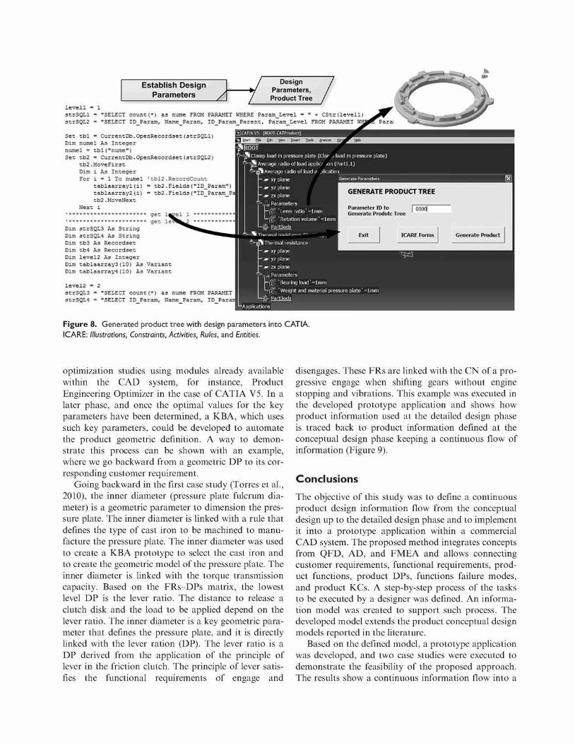
mechanical clutch was chosen (Torres et al., 2010). With the design information defined up to now, the subject of the case study is not yet geometrically defined but the basis information needed for its detailed definition is captured and stored in the database, including MOKA ICARE forms, fn particular, the pressure plate is defined by DPs that mainly relates to geometrical shapes and dimensions. The execution of the tasks is iterative and ends when all the requirements and parameters are defined and related. Based on the hierarchical structure of DPs and considering the type of each parameter (product, part and design), the product tree is created in CATf A when clicking in the button "Generate Product Tree" (Figure 7). The parameters of type "design" are mapped into the CATfA concept of "parameter." Figure 8 shows the example of the clutch pressure plate and the parameter "lever ratio." The left-hand side of Figure 8 shows a fragment of code from a function to search the parent-child relationships to define the hierarchy of parameters in the CATfA product tree.
Methodology and case study discussion
The proposed method combines the following three design techniques: QFD, AD, and FMEA, to define a
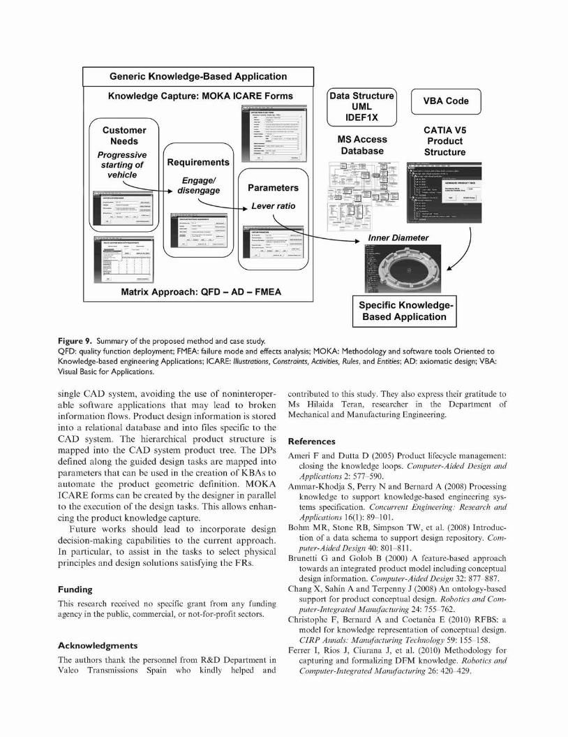
step-by-step guided process supported by a continuous product information flow from the conceptual design up to the detailed design phase. The matrix-based definition of relationships between CNs, FRs, and DPs and the functional and structural decomposition, proposed by AD, allows tracing back and forth key DPs, functional requirements, and CNs. Key DPs can then be used to develop KBAs to automate the product geometric definition, which is once generated should be compliant with the needs and requirements defined at the conceptual design phase. Along the guided process, using MOKA ICARE forms, product knowledge can be captured to help in developing KBAs. To evaluate its applicability in an industrial environment, it was necessary to demonstrate how this approach could be integrated into a commercial CAD system. Figure 8 shows a summary of the proposed method.
The product information traceability back and forth within the CAD system is a relevant aspect that should help in creating designs compliant with the needs and requirements defined at the conceptual design phase. The first product structure generated within the CAD systems provides no geometry, but it comprises the key parameters to be used along the embodiment and detailed design phases. Such parameters can be used in
Establish Design Parameters /
Design Parameters, Product Tree
levell = strSQLl strSQL2
"SELECT countC) as nume FROM PARAMET WHERE Param_Level = " + CStr (levell) "SELECT ID_Param, Name_Parara, ID_Param_Parent, Param_Level FROM PARAMET WH.
Sec tbl = CurrentDb.OpenRecordset(strSQLl) Dim numel As Integer numel = tbl ("nume") Set tb2 = CurrentDb.OpenRecordset(strSQL2)
tb2.MoveFirst Dim i A3 Integer For i • 1 To numel
tablaarrayl(i) tablaarray2(i) tb2.MoveNext
Next i
CATIA V5 - [ROOT.CATProductj
I Start Fde
IflOOT •»!p Clamp load in pressure p
riJiVlsMsTiEliS
tbl2.RecordCount tb2.Fields("ID_Parara") tb2.Fields ("ID_Param_Pal
" ********************** get la i********************** g e c i^j
Dim strSQL3 As String Dim strSQL4 As String Dim tb3 As Recordset Dim tb4 As Recordset Dim level2 As Integer Dim tablaarray3(10) As Variant Dim tablaarrayl(10) As Variant
level2 = 2 strSQL3 = "SELECT count(*) as nume FROM strSQL4 = "SELECT ID Param, Name Param, ID Para
tSl Average radio of load a plication
E ' "Rotation volume* =lmn
1 in pressure plate)
GENERATE PRODUCT TREE
Parameter ID to I oooo( Generate Produtc Tree
Generate Product
|— rfj>" "Bearing load"=lmm Mr "Weight and material pressure plate* =lmm
$-PartB
Figure 8. Generated product tree with design parameters into CATIA. ICAR.E: Illustrations, Constraints, Activities, Rules, and Entities.
optimization studies using modules already available within the CAD system, for instance, Product Engineering Optimizer in the case of CATIA V5. In a later phase, and once the optimal values for the key parameters have been determined, a KBA, which uses such key parameters, could be developed to automate the product geometric definition. A way to demonstrate this process can be shown with an example, where we go backward from a geometric DP to its corresponding customer requirement.
Going backward in the first case study (Torres et al., 2010), the inner diameter (pressure plate fulcrum diameter) is a geometric parameter to dimension the pressure plate. The inner diameter is linked with a rule that defines the type of cast iron to be machined to manufacture the pressure plate. The inner diameter was used to create a KBA prototype to select the cast iron and to create the geometric model of the pressure plate. The inner diameter is linked with the torque transmission capacity. Based on the FRs-DPs matrix, the lowest level DP is the lever ratio. The distance to release a clutch disk and the load to be applied depend on the lever ratio. The inner diameter is a key geometric parameter that defines the pressure plate, and it is directly linked with the lever ration (DP). The lever ratio is a DP derived from the application of the principle of lever in the friction clutch. The principle of lever satisfies the functional requirements of engage and
disengages. These FRs are linked with the CN of a progressive engage when shifting gears without engine stopping and vibrations. This example was executed in the developed prototype application and shows how product information used at the detailed design phase is traced back to product information defined at the conceptual design phase keeping a continuous flow of information (Figure 9).
Conclusions
The objective of this study was to define a continuous product design information flow from the conceptual design up to the detailed design phase and to implement it into a prototype application within a commercial CAD system. The proposed method integrates concepts from QFD, AD, and FMEA and allows connecting customer requirements, functional requirements, product functions, product DPs, functions failure modes, and product KCs. A step-by-step process of the tasks to be executed by a designer was defined. An information model was created to support such process. The developed model extends the product conceptual design models reported in the literature.
Based on the defined model, a prototype application was developed, and two case studies were executed to demonstrate the feasibility of the proposed approach. The results show a continuous information flow into a
Generic Knowledge-Based Application
Knowledge Capture: MOKA ICARE Forms
Customer Needs
Progressive starting of
vehicle Requirements
Matrix Approach: QFD - AD - FMEA
Data Structure UML
IDEF1X
VBA Code
MS Access Database
CATIA V5 Product
Structure
§c Specific Knowledge-Based Application
Figure 9. Summary of the proposed method and case study. QFD: quality function deployment; FMEA: failure mode and effects analysis; MOKA: Methodology and software tools Oriented to Knowledge-based engineering Applications; ICARE: Illustrations, Constraints, Activities, Rules, and Entities; AD: axiomatic design; VBA: Visual Basic for Applications.
single C A D system, avoiding the use of noninteroper-able software applications that may lead to broken information flows. Product design information is stored into a relational database and into files specific to the CAD system. The hierarchical product structure is mapped into the C A D system product tree. The DPs defined along the guided design tasks are mapped into parameters that can be used in the creation of KBAs to automate the product geometric definition. M O K A ICARE forms can be created by the designer in parallel to the execution of the design tasks. This allows enhancing the product knowledge capture.
Future works should lead to incorporate design decision-making capabilities to the current approach. In particular, to assist in the tasks to select physical principles and design solutions satisfying the FRs.
Funding
This research received no specific grant from any funding agency in the public, commercial, or not-for-profit sectors.
Acknowledgments
The authors thank the personnel from R&D Department in Valeo Transmissions Spain who kindly helped and
contributed to this study. They also express their gratitude to Ms Hilaida Teran, researcher in the Department of Mechanical and Manufacturing Engineering.
References
Ameri F and Dutta D (2005) Product lifecycle management: closing the knowledge loops. Computer-Aided Design and Applications 2: 577-590.
Ammar-Khodja S, Perry N and Bernard A (2008) Processing knowledge to support knowledge-based engineering systems specification. Concurrent Engineering: Research and Applications 16(1): 89-101.
Bohm MR, Stone RB, Simpson TW, et al. (2008) Introduction of a data schema to support design repository. Computer-Aided Design 40: 801-811.
Brunetti G and Golob B (2000) A feature-based approach towards an integrated product model including conceptual design information. Computer-Aided Design 32: 877-887.
Chang X, Sahin A and Terpenny J (2008) An ontology-based support for product conceptual design. Robotics and Computer-Integrated Manufacturing 24: 755-762.
Christophe F, Bernard A and Coetanea E (2010) RFBS: a model for knowledge representation of conceptual design. CIRP Annals: Manufacturing Technology 59: 155-158.
Ferrer I, Rios J, Ciurana J, et al. (2010) Methodology for capturing and formalizing DFM knowledge. Robotics and Computer-Integrated Manufacturing 26: 420^-29.

Gero JS (1990) Design prototypes: a knowledge representation schema for design. Al Magazine 11(4): 26-36.
Guerra-Zubiaga DA, Rios-Soltero EF, Ramon-Raygoza ED, et al. (2007) PLM tools taxonomy to support the design process. In: Proceedings of international conference on comprehensive product realization, June 18-20, Beijing, China.
OMG (2010) OMG Systems Modeling Language (SysML). Available at: http://www.omg.org/spec/SysML/L2/
Prasad B (2000) Converting computer-integrated manufacturing into an intelligent information system by combining CIM with concurrent engineering and knowledge management. Industrial Management &Data Systems 100(7): 301-316.
Skarka W (2007) Application of MOKA methodology in generative model creation using CATIA. Engineering Applications of Artificial Intelligence 20: 677-690.
Starcevic N, Raiff T, Bux M, et al. (2010) Computer-aided strategic optimization of a robot for biomass processing. Biosystems Engineering 105: 13-24.
Tay F and Gu J (2002) Product modeling for conceptual design support. Computers in Industry 48: 143-155.
Torres V, Rios J, Vizan A, et al. (2010) Integration of design tools and knowledge capture into a CAD system: a case study. Concurrent Engineering: Research and Applications 18(4): 311-324.
Wang L, Shen W, Xie H, et al. (2002) Collaborative conceptual design—state of the art and future trends. Computer-Aided Design 34: 981-996.
Zheng LY, Liu Q and McMahon CA (2010) Integration of process FMEA with product and process design based on key characteristics. Advances in Soft Computing 66: 1673-1686.
Zheng P, Torres VH, Rios J, et al. (2012) Integration of conceptual design and MOKA into CATIA V5: a knowledge-based application for an aircraft Y-bolt component. In: Proceedings of the international conference on frontiers of manufacturing and design science (ICFMD 2012), December 11-13, Hong Kong, China.
Biographies
^**v Victor H. Torres is a PhD student at Polytechnic University of Madrid in the Department of Mechanical and Manufacturing Engineering. He has an MSc degree in Manufacturing Systems. During his PhD studies, he has
' made research practicum at R&D Department in Valeo Transmissions Spain and at Airbus Spain through Atos i s _ ^ C Origin SAE. His research interests include design methodologies and tools, KBE, CAD systems, and concurrent | ^ ^ | engineering.
Jose Rios is a senior lecturer in the Department of Mechanical and Manufacturing Engineering at Polytechnic University of Madrid. He has been involved in research projects related to manufacturing planning, CAD/CAM,
k information modeling, KBE, and design integration. He has collaborated with different companies in the aeronautical, automotive, and die and mould-making sectors. Along his professional career, he held a Visiting Research position at Penn State University (USA) and a Research Fellow position at Cranfield University (UK).
Antonio Vizan is a professor in the Department of Mechanical and Manufacturing Engineering at Polytechnic University of Madrid. He leads research and collaboration with companies and national research centers in the areas of design and production. He held a position of Head of the Department of Mechanical and Manufacturing Engineering and Vice Director of the Spanish Association for Robotics and Automation of Production. His research interest relates to machining process optimization, micromachining, injection molding, and concurrent engineering.
Jesus M. Perez is a professor in the Department of Mechanical and Manufacturing Engineering at Polytechnic University of Madrid. He has led research projects and publication studies in topics related to forming processes, dimensional metrology, process improvement and control, quality, and instrumentation. He held a position of Vice Director for Research in the Industrial Engineering School. His areas of interest include improvement of manufacturing processes, quality control and instrumentation, and concurrent engineering.