architecture and design - vmware · architecture and design thevmware validated design architecture...
TRANSCRIPT
Architecture and DesignModified on 30 OCT 2018VMware Validated Design 4.3VMware Validated Design for Software-Defined DataCenter 4.3
Architecture and Design
VMware, Inc. 2
You can find the most up-to-date technical documentation on the VMware website at:
https://docs.vmware.com/
If you have comments about this documentation, submit your feedback to
Copyright © 2016–2018 VMware, Inc. All rights reserved. Copyright and trademark information.
VMware, Inc.3401 Hillview Ave.Palo Alto, CA 94304www.vmware.com
Contents
About VMware Validated Design Architecture and Design 4
Updated Information 5
1 Architecture Overview 6
Infrastructure Architecture 8
Virtual Infrastructure Architecture 18
Operations Management Architecture 26
Cloud Management Architecture 43
Business Continuity Architecture 51
2 Detailed Design 55
Physical Infrastructure Design 56
Virtual Infrastructure Design 78
Operations Management Design 170
Cloud Management Design 238
Business Continuity Design 279
VMware, Inc. 3
About VMware Validated DesignArchitecture and Design
TheVMware Validated Design Architecture and Design document contains a validated model of theSoftware-Defined Data Center (SDDC) and provides a detailed design of each management componentof the SDDC stack.
Chapter 1 Architecture Overview discusses the building blocks and the main principles of each SDDCmanagement layer. Chapter 2 Detailed Design provides the available design options according to thedesign objective, and a set of design decisions to justify selecting the path for building each SDDCcomponent.
Intended AudienceVMware Validated Design Architecture and Design is intended for cloud architects, infrastructureadministrators and cloud administrators who are familiar with and want to use VMware software to deployin a short time and manage an SDDC that meets the requirements for capacity, scalability, backup andrestore, and extensibility for disaster recovery support.
Required VMware SoftwareVMware Validated Design Architecture and Design is compliant and validated with certain productversions. See VMware Validated Design Release Notes for more information about supported productversions.
VMware, Inc. 4
Updated Information
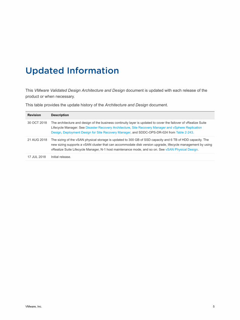
This VMware Validated Design Architecture and Design document is updated with each release of theproduct or when necessary.
This table provides the update history of the Architecture and Design document.
Revision Description
30 OCT 2018 The architecture and design of the business continuity layer is updated to cover the failover of vRealize SuiteLifecycle Manager. See Disaster Recovery Architecture, Site Recovery Manager and vSphere ReplicationDesign, Deployment Design for Site Recovery Manager, and SDDC-OPS-DR-024 from Table 2‑243.
21 AUG 2018 The sizing of the vSAN physical storage is updated to 300 GB of SSD capacity and 6 TB of HDD capacity. Thenew sizing supports a vSAN cluster that can accommodate disk version upgrade, lifecycle management by usingvRealize Suite Lifecycle Manager, N-1 host maintenance mode, and so on. See vSAN Physical Design.
17 JUL 2018 Initial release.
VMware, Inc. 5
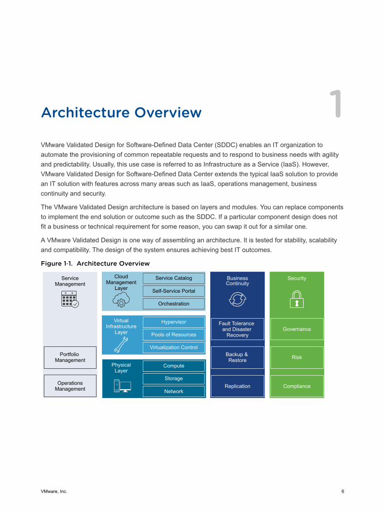
Architecture Overview 1VMware Validated Design for Software-Defined Data Center (SDDC) enables an IT organization toautomate the provisioning of common repeatable requests and to respond to business needs with agilityand predictability. Usually, this use case is referred to as Infrastructure as a Service (IaaS). However,VMware Validated Design for Software-Defined Data Center extends the typical IaaS solution to providean IT solution with features across many areas such as IaaS, operations management, businesscontinuity and security.
The VMware Validated Design architecture is based on layers and modules. You can replace componentsto implement the end solution or outcome such as the SDDC. If a particular component design does notfit a business or technical requirement for some reason, you can swap it out for a similar one.
A VMware Validated Design is one way of assembling an architecture. It is tested for stability, scalabilityand compatibility. The design of the system ensures achieving best IT outcomes.
Figure 1‑1. Architecture Overview
ServiceManagement
Portfolio Management
OperationsManagement
CloudManagement
Layer
Service Catalog
Self-Service Portal
Orchestration
BusinessContinuity
Fault Tolerance and Disaster
Recovery
Backup & Restore
Hypervisor
Pools of Resources
Virtualization Control
VirtualInfrastructure
Layer
Compute
Storage
Network
PhysicalLayer
Security
Replication Compliance
Risk
Governance
VMware, Inc. 6
Physical LayerThe lowest layer of the solution is the physical layer which consists of the compute, network and storagecomponents. The compute component contains the x86-based servers that run the management, edgeand tenant workloads. This design provides some guidance about the physical capabilities that arerequired to run this architecture. However, you select a specific type or brand of hardware according toVMware Compatibility Guide.
Virtual Infrastructure LayerThe virtual infrastructure layer is on top of the physical layer components. The virtual infrastructure layercontrols the access to the underlying physical infrastructure, and controls and allocates resources to themanagement and tenant workloads. The management workloads consist of elements in the virtualinfrastructure layer itself, together with elements in the cloud management, service management,business continuity and security layers.
Cloud Management LayerThe cloud management layer is the top layer of the stack. Service consumption occurs at this layer.
This layer requests resources and orchestrates the actions of the lower layers from a user interface orapplication programming interface (API).
Service Management LayerWhen building any type of IT infrastructure, you use portfolio and operations management for continuousday-to-day service delivery. The service management area of this architecture focuses on operationsmanagement, in particular lifecycle management, monitoring, alerting, and log management.
Operations Management LayerThe architecture of the operations management layer includes management components that providesupport for the main types of operations in an SDDC.
In the operations management layer, you monitor the underlying physical infrastructure and the virtualmanagement and tenant workloads in real-time. Information is collected in the form of structured data(metrics) and unstructured data (logs). The operations management layer also retrieves the SDDCtopology, that is physical and virtual compute, networking, and storage resources, which are key inintelligent and dynamic operational management. The operations management layer consists primarily ofmonitoring and logging functionality.
Architecture and Design
VMware, Inc. 7
Business Continuity LayerAn enterprise-ready system must contain elements to support business continuity by providing databackup, restoration, and disaster recovery. If data loss occurs, the right elements must be in place toprevent permanent loss of business critical data. This design provides guidance on how to operatebackup and restore functions, and includes run books with detailed information on how to fail overcomponents in the event of a disaster.
Security LayerAll systems must be secure by design. A secure design reduces risk and increases compliance whileproviding a governance structure. The security layer outlines the operations and setup that you mustprovide to implement an SDDC that is resilient to both internal and external threats.
This chapter includes the following topics:
n Infrastructure Architecture
n Virtual Infrastructure Architecture
n Operations Management Architecture
n Cloud Management Architecture
n Business Continuity Architecture
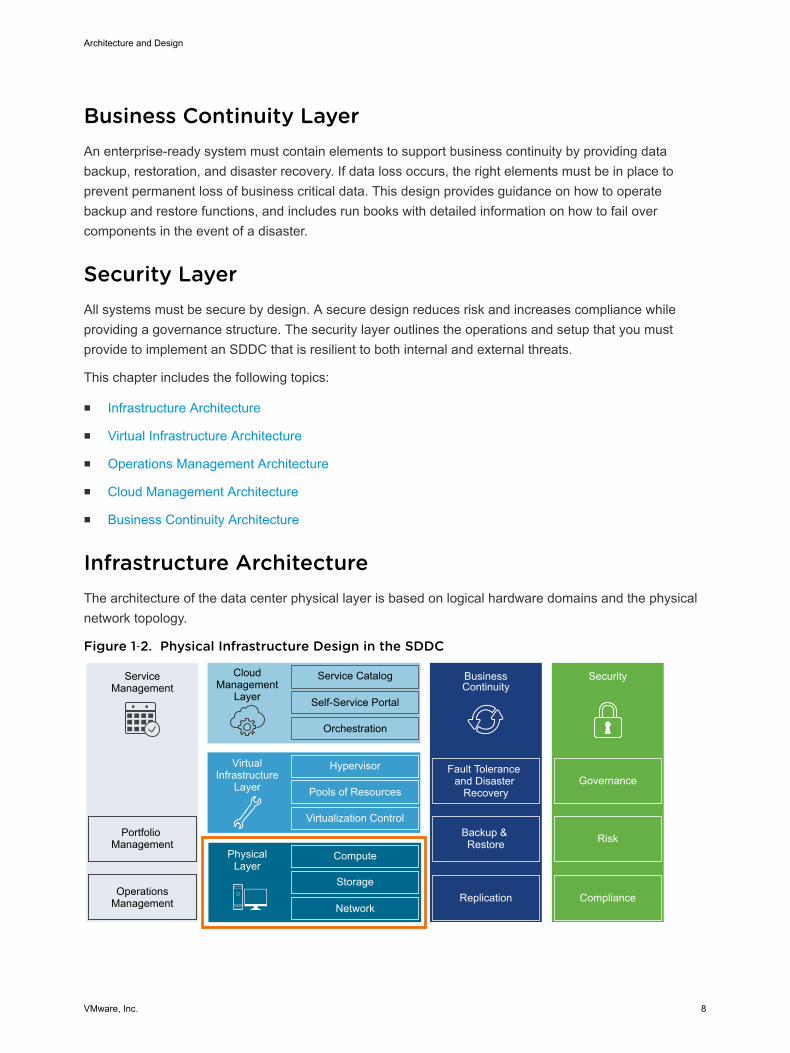
Infrastructure Architecture The architecture of the data center physical layer is based on logical hardware domains and the physicalnetwork topology.
Figure 1‑2. Physical Infrastructure Design in the SDDC
ServiceManagement
Portfolio Management
OperationsManagement
CloudManagement
Layer
Service Catalog
Self-Service Portal
Orchestration
BusinessContinuity
Fault Tolerance and Disaster
Recovery
Backup & Restore
Hypervisor
Pools of Resources
Virtualization Control
VirtualInfrastructure
Layer
Compute
Storage
Network
PhysicalLayer
Security
Replication Compliance
Risk
Governance
Architecture and Design
VMware, Inc. 8
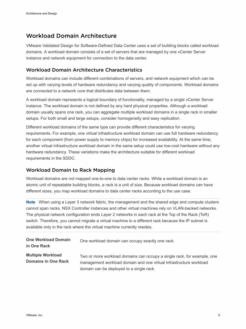
Workload Domain Architecture VMware Validated Design for Software-Defined Data Center uses a set of building blocks called workloaddomains. A workload domain consists of a set of servers that are managed by one vCenter Serverinstance and network equipment for connection to the data center.
Workload Domain Architecture CharacteristicsWorkload domains can include different combinations of servers, and network equipment which can beset up with varying levels of hardware redundancy and varying quality of components. Workload domainsare connected to a network core that distributes data between them.
A workload domain represents a logical boundary of functionality, managed by a single vCenter Serverinstance. The workload domain is not defined by any hard physical properties. Although a workloaddomain usually spans one rack, you can aggregate multiple workload domains in a single rack in smallersetups. For both small and large setups, consider homogeneity and easy replication .
Different workload domains of the same type can provide different characteristics for varyingrequirements. For example, one virtual infrastructure workload domain can use full hardware redundancyfor each component (from power supply to memory chips) for increased availability. At the same time,another virtual infrastructure workload domain in the same setup could use low-cost hardware without anyhardware redundancy. These variations make the architecture suitable for different workloadrequirements in the SDDC.
Workload Domain to Rack MappingWorkload domains are not mapped one-to-one to data center racks. While a workload domain is anatomic unit of repeatable building blocks, a rack is a unit of size. Because workload domains can havedifferent sizes, you map workload domains to data center racks according to the use case.
Note When using a Layer 3 network fabric, the management and the shared edge and compute clusterscannot span racks. NSX Controller instances and other virtual machines rely on VLAN-backed networks.The physical network configuration ends Layer 2 networks in each rack at the Top of the Rack (ToR)switch. Therefore, you cannot migrate a virtual machine to a different rack because the IP subnet isavailable only in the rack where the virtual machine currently resides.
One Workload Domainin One Rack
One workload domain can occupy exactly one rack.
Multiple WorkloadDomains in One Rack
Two or more workload domains can occupy a single rack, for example, onemanagement workload domain and one virtual infrastructure workloaddomain can be deployed to a single rack.
Architecture and Design
VMware, Inc. 9
Single WorkloadDomain Across MultipleRacks
A single workload domain can stretch across multiple adjacent racks. Forexample, a virtual infrastructure workload domain that has more ESXi hoststhan a single rack can support.
Stretched WorkloadDomain AcrossAvailability Zones
A cluster in a single workload domain can span across two availabilityzones by using vSAN stretched clustering.
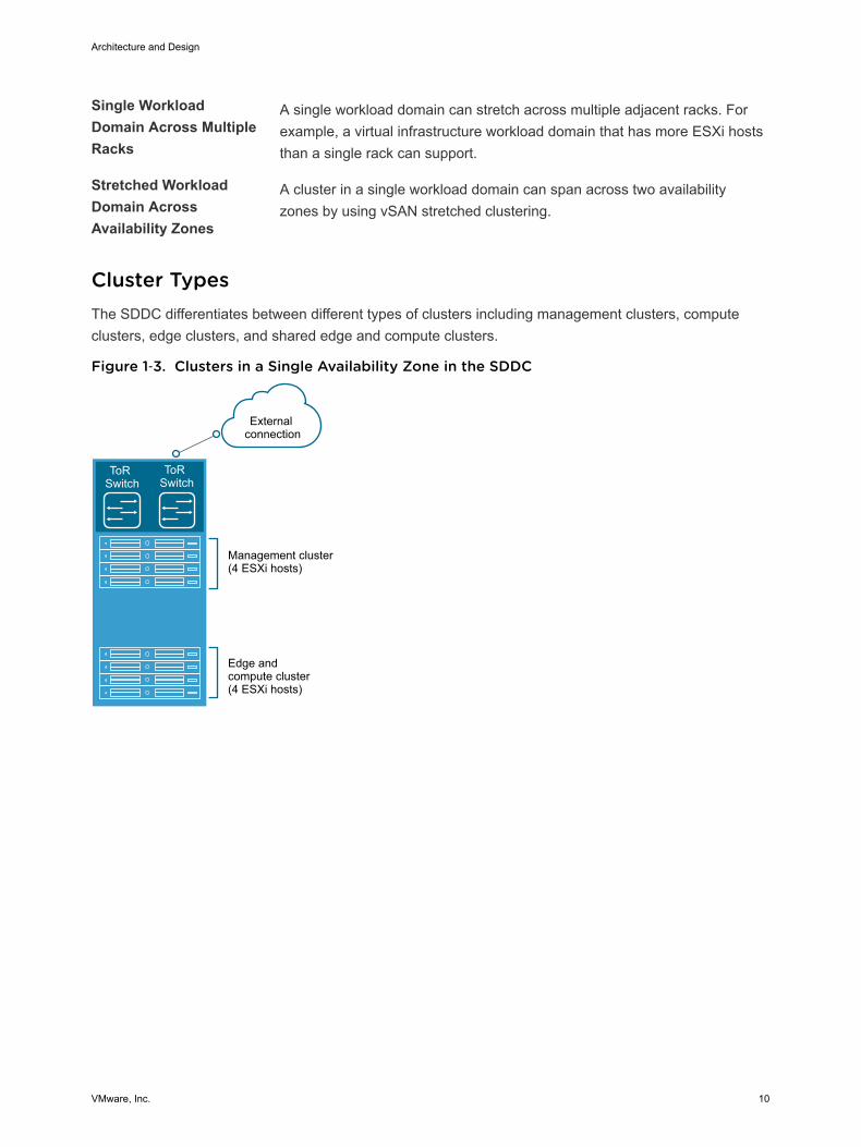
Cluster Types The SDDC differentiates between different types of clusters including management clusters, computeclusters, edge clusters, and shared edge and compute clusters.
Figure 1‑3. Clusters in a Single Availability Zone in the SDDC
ToR Switch
ToR Switch
Management cluster(4 ESXi hosts)
Edge and compute cluster(4 ESXi hosts)
External connection
Architecture and Design
VMware, Inc. 10

Figure 1‑4. Clusters in Two Availability Zones in the SDDC
Availability Zone 1
Management cluster(4 ESXi hosts)
Еdge andcompute cluster(4 ESXi hosts)
ToR Switch
ToR Switch
Stretchedmanagement clusterAvailability Zone 1(4 ESXi hosts)
Stretched sharededge andcompute clusterAvailability Zone 1(4 ESXi hosts)
External connection
External connection
External connection
ToR Switch
ToR Switch
Stretchedmanagement clusterAvailability Zone 2(4 ESXi hosts)
Stretched sharededge and compute clusterAvailability Zone 2(4 ESXi hosts)
ToR Switch
ToR Switch
Availability Zone 2
Region A Region B
Management ClusterThe management cluster lives in the management workload domain and runs the virtual machines thatmanage the SDDC. These virtual machines host vCenter Server, vSphere Update Manager, NSXManager, NSX Controller, vRealize Operations Manager, vRealize Automation, vRealize Log Insight, andother management components. Because the management cluster contains critical infrastructure,consider implementing a basic level of hardware redundancy for this cluster.
Management cluster components must not have tenant-specific addressing.
Shared Edge and Compute ClusterThe shared edge and compute cluster is the first cluster in the virtual infrastructure workload domain andhosts the tenant virtual machines (sometimes referred to as workloads or payloads). This shared clusteralso runs the required NSX services to enable North-South routing between the SDDC tenant virtualmachines and the external network, and east-west routing inside the SDDC. As the SDDC expands, youcan add more compute-only clusters to support a mix of different types of workloads for different types ofService Level Agreements (SLAs).
Compute ClusterCompute clusters live in a virtual infrastructure workload domain and host the SDDC tenant workloads.An SDDC can contain different types of compute clusters and provide separate compute pools fordifferent types of SLAs.
Architecture and Design
VMware, Inc. 11
External StorageExternal storage provides non-vSAN storage using NFS, iSCSI or Fiber Channel. Different types ofstorage can provide different levels of SLA, ranging from just a bunch of disks (JBODs) using IDE driveswith minimal to no redundancy, to fully redundant enterprise-class storage arrays.
Physical Network Architecture VMware Validated Design for Software-Defined Data Center can use most physical network architectures.In an SDDC, you consider Layer 2 or Layer 3 transport, using quality of service tags for prioritized traffichandling on the network devices, NIC configuration on the physical servers, and VLAN port modes onboth physical servers and network equipment.
Network Transport You can implement the switch fabric at the physical layer of an SDDC by providing Layer 2 or Layer 3transport services. For a scalable and vendor-neutral data center network, use a Layer 3 transport.
VMware Validated Design supports both Layer 2 and Layer 3 transports. When you decide whether to useLayer 2 or Layer 3, consider the following factors:
n NSX ECMP Edge devices establish Layer 3 routing adjacency with the first upstream Layer 3 deviceto provide equal cost routing for management and workload traffic.
n The investment you have today in your current physical network infrastructure.
n The benefits and drawbacks for both Layer 2 and Layer 3 designs.
Benefits and Drawbacks of Layer 2 Transport
A design using Layer 2 transport has these considerations:
n In a design that uses Layer 2 transport, top of rack switches and upstream Layer 3 devices, such ascore switches or routers, form a switched fabric.
n The upstream Layer 3 devices end each VLAN and provide default gateway functionality.
n Uplinks from the top of rack switch to the upstream Layer 3 devices are 802.1Q trunks carrying allrequired VLANs.
Using a Layer 2 transport has the following benefits and drawbacks:
Table 1‑1. Benefits and Drawbacks of Layer 2 Transport
Characteristic Description
Benefits n More design freedom.n You can span VLANs, which can be useful in some circumstances.
Drawbacks n The size of such a deployment is limited because the fabric elements haveto share a limited number of VLANs.
n You might have to rely on a specialized data center switching fabric productfrom a single vendor.
Architecture and Design
VMware, Inc. 12
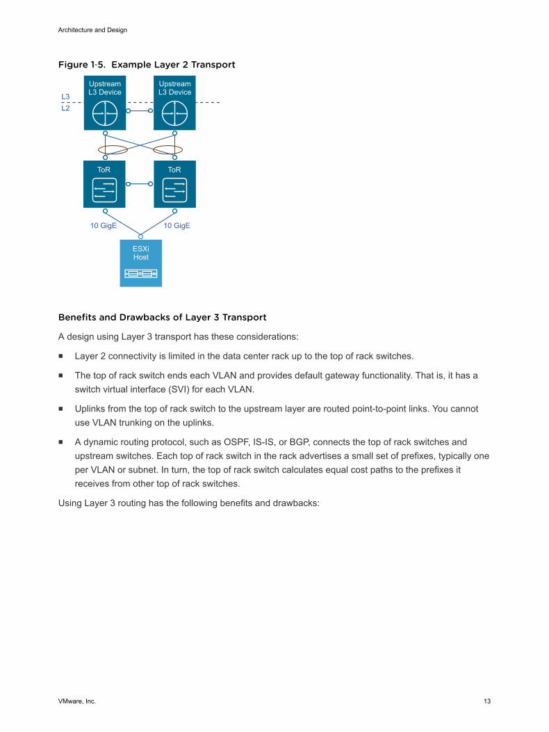
Figure 1‑5. Example Layer 2 Transport
ToR ToR
ESXiHost
Upstream L3 DeviceL3
10 GigE 10 GigE
L2
Upstream L3 Device
Benefits and Drawbacks of Layer 3 Transport
A design using Layer 3 transport has these considerations:
n Layer 2 connectivity is limited in the data center rack up to the top of rack switches.
n The top of rack switch ends each VLAN and provides default gateway functionality. That is, it has aswitch virtual interface (SVI) for each VLAN.
n Uplinks from the top of rack switch to the upstream layer are routed point-to-point links. You cannotuse VLAN trunking on the uplinks.
n A dynamic routing protocol, such as OSPF, IS-IS, or BGP, connects the top of rack switches andupstream switches. Each top of rack switch in the rack advertises a small set of prefixes, typically oneper VLAN or subnet. In turn, the top of rack switch calculates equal cost paths to the prefixes itreceives from other top of rack switches.
Using Layer 3 routing has the following benefits and drawbacks:
Architecture and Design
VMware, Inc. 13

Table 1‑2. Benefits and Drawbacks of Layer 3 Transport
Characteristic Description
Benefits n You can select from many Layer 3 capable switch products for the physicalswitching fabric.
n You can mix switches from different vendors because of the generalinteroperability between the implementation of OSPF, IS-IS or BGP.
n This approach is typically more cost effective because it uses only thebasic functionality of the physical switches.
Drawbacks n VLANs are restricted to a single rack. The restriction can affect vSphereFault Tolerance and storage networks.
To overcome this limitation, use Layer 2 bridging in NSX.
Figure 1‑6. Example Layer 3 Transport
ToR
L3
ESXiHost
UpstreamSwitch
UpstreamSwitch
WAN/MPLSInternet
WAN/MPLSInternet
ToR
L2
10 GigE10 GigE
Infrastructure Network Architecture An important goal of network virtualization is to provide a virtual-to-physical network abstraction.
To implement a virtual-to-physical network abstraction, the physical fabric must provide a robust IPtransport with the following characteristics:
n Simplicity
n Scalability
n High bandwidth
n Fault-tolerant transport
n Support for different levels of quality of service (QoS)
Architecture and Design
VMware, Inc. 14
Simplicity and Scalability
Simplicity and scalability are the first and most critical requirements for networking.
Simplicity
Switch configuration in a data center must be simple. General or global configuration such as AAA,SNMP, syslog, NTP, and others should be replicated line by line, independent of the position of theswitches. A central management capability to configure all switches at once is an alternative.
Restrict configurations that are unique to the switches such as multi-chassis link aggregation groups,VLAN IDs, and dynamic routing protocol configuration.
Scalability
Scalability factors include, but are not limited to, the following:
n Number of racks supported in a fabric.
n Amount of bandwidth between any two racks in a data center.
n Number of paths between racks.
The total number of ports available across all switches and the oversubscription that is acceptabledetermine the number of racks supported in a fabric. Different racks might host different types ofinfrastructure, which can result in different bandwidth requirements.
n Racks with IP storage systems might receive or source more traffic than other racks.
n Compute racks, such as racks hosting hypervisors with virtual machines, might have differentbandwidth requirements than shared edge and compute racks, which provide connectivity to theoutside world.
Link speed and number of links vary to satisfy different bandwidth demands. You can modify them foreach rack.
Quality of Service Differentiation
Virtualized environments carry different types of traffic, including tenant, storage and management traffic,across the switching infrastructure. Each traffic type has different characteristics and has differentdemands on the physical switching infrastructure.
n Management traffic, although typically low in volume, is critical for controlling physical and virtualnetwork state.
n IP storage traffic is typically high in volume and generally remains in the boundaries of a data center.
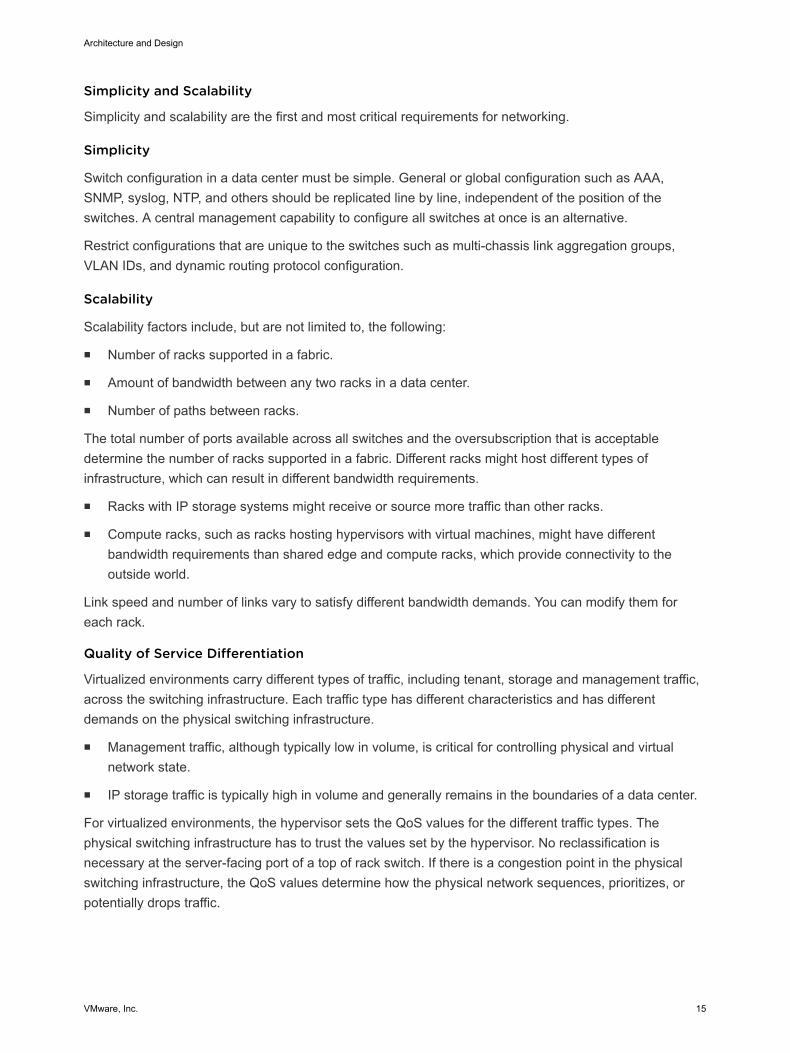
For virtualized environments, the hypervisor sets the QoS values for the different traffic types. Thephysical switching infrastructure has to trust the values set by the hypervisor. No reclassification isnecessary at the server-facing port of a top of rack switch. If there is a congestion point in the physicalswitching infrastructure, the QoS values determine how the physical network sequences, prioritizes, orpotentially drops traffic.
Architecture and Design
VMware, Inc. 15
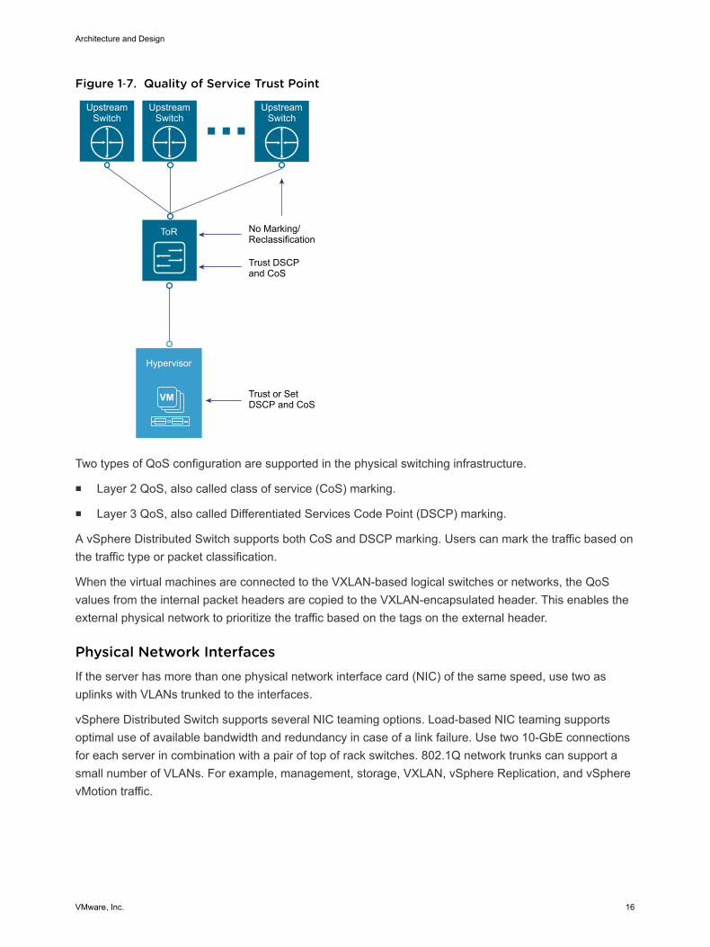
Figure 1‑7. Quality of Service Trust Point
VM
ToR
Trust or Set DSCP and CoS
Trust DSCP and CoS
Hypervisor
No Marking/Reclassification
Upstream Switch
Upstream Switch
Upstream Switch
Two types of QoS configuration are supported in the physical switching infrastructure.
n Layer 2 QoS, also called class of service (CoS) marking.
n Layer 3 QoS, also called Differentiated Services Code Point (DSCP) marking.
A vSphere Distributed Switch supports both CoS and DSCP marking. Users can mark the traffic based onthe traffic type or packet classification.
When the virtual machines are connected to the VXLAN-based logical switches or networks, the QoSvalues from the internal packet headers are copied to the VXLAN-encapsulated header. This enables theexternal physical network to prioritize the traffic based on the tags on the external header.
Physical Network Interfaces If the server has more than one physical network interface card (NIC) of the same speed, use two asuplinks with VLANs trunked to the interfaces.
vSphere Distributed Switch supports several NIC teaming options. Load-based NIC teaming supportsoptimal use of available bandwidth and redundancy in case of a link failure. Use two 10-GbE connectionsfor each server in combination with a pair of top of rack switches. 802.1Q network trunks can support asmall number of VLANs. For example, management, storage, VXLAN, vSphere Replication, and vSpherevMotion traffic.
Architecture and Design
VMware, Inc. 16
Availability Zones and Regions In an SDDC, availability zones are collections of infrastructure components. Each availability zone isisolated from other availability zones to prevent the propagation of failure or outage across the datacenter. Regions support disaster recovery solutions and you can place workloads closer to yourcustomers. Usually, multiple availability zones form a single region.
This VMware Validated Design uses two regions, with the option to use one or two availability zones inRegion A and single availability zone in Region B. You can expand the design to include multipleavailability zones.
Figure 1‑8. Availability Zones and Regions
AvailabilityZone 1
AvailabilityZone 1
AvailabilityZone 2
FutureAvailability
ZoneFuture
AvailabilityZone
Region B: LAXRegion A: SFO
Availability Zones In a region, each availability zone is isolated from the other availability zones to prevent reproducingfailure or outage across zone boundaries.
Using multiple availability zones provides high availability through redundancy.
Architecture and Design
VMware, Inc. 17

Table 1‑3. Characteristics of Availability Zones
Availability Zone Characteristic Description
Outage prevention You avoid outages and improve SLAs. An outage that is caused by external factors, suchas power supply, cooling, and physical integrity, affects only one zone. These factors donot cause outage in other zones except in the case of major disasters.
Reliability Each availability zone runs on its own physically distinct, independent infrastructure, andis engineered to be highly reliable. Each zone should have independent power, cooling,network, and security. Do not share common points of failures in a physical data center,like generators and cooling equipment, across availability zones. Additionally, thesezones should be physically separate so that even uncommon disasters affect only onezone.
Availability zones are either two distinct data centers in a metro distance, or two safety orfire sectors (data halls) in the same large-scale data center.
Distance between zones Multiple availability zones belong to a single region. The physical distance betweenavailability zones is short enough to offer low, single-digit latency (less than 5 ms) andlarge bandwidth (10 Gbps) between the zones.
You can operate workloads across multiple availability zones in the same region as if theywere part of a single virtual data center. This architecture supports high availability that issuitable for mission critical applications.
If the distance between two locations of equipment becomes too large, these locationscan no longer function as two availability zones in the same region and must be treatedas separate regions.
Regions By using multiple regions, you can place workloads closer to your customers. For example, you canoperate one region on the US East Coast and one region on the US West Coast, or operate a region inEurope and another region in the US.
Using regions has the following advantages:
n Support disaster recovery solutions. One region can be the primary site and another region can bethe recovery site.
n Address data privacy laws and restrictions in certain countries by storing tenant data in a region in thesame country.
The distance between regions can be large. The latency between regions must be less than 150 ms.
This validated design uses two example regions: Region A, in San Francisco (SFO), and Region B, in LosAngeles (LAX).
Virtual Infrastructure Architecture The virtual infrastructure is the foundation of SDDC. It contains the software-defined infrastructure,software-defined networking and software-defined storage. The virtual infrastructure layer runs theoperations management layer and the Cloud Management Platform.
Architecture and Design
VMware, Inc. 18
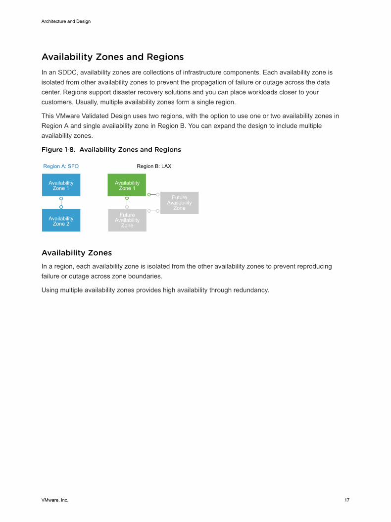
In the virtual infrastructure layer, access to the underlying physical infrastructure is controlled andallocated to the management and tenant workloads. The virtual infrastructure layer consists of thehypervisors on the physical hosts and the control of these hypervisors. The management components ofthe SDDC consist of elements in the virtual management layer itself, along with elements in the cloudmanagement layer, or in the operations management, business continuity, or security areas.
Figure 1‑9. Virtual Infrastructure Layer in the SDDC
ServiceManagement
Portfolio Management
OperationsManagement
CloudManagement
Layer
Service Catalog
Self-Service Portal
Orchestration
BusinessContinuity
Fault Tolerance and Disaster
Recovery
Backup & Restore
Hypervisor
Pools of Resources
Virtualization Control
VirtualInfrastructure
Layer
Compute
Storage
Network
PhysicalLayer
Security
Replication Compliance
Risk
Governance
Virtual Infrastructure Overview The SDDC virtual infrastructure consists of two regions. Each region includes a management workloaddomain that contains the management cluster and a virtual infrastructure workload domain that containsthe shared edge and compute cluster. Clusters in Region A can use two availability zones.
Architecture and Design
VMware, Inc. 19
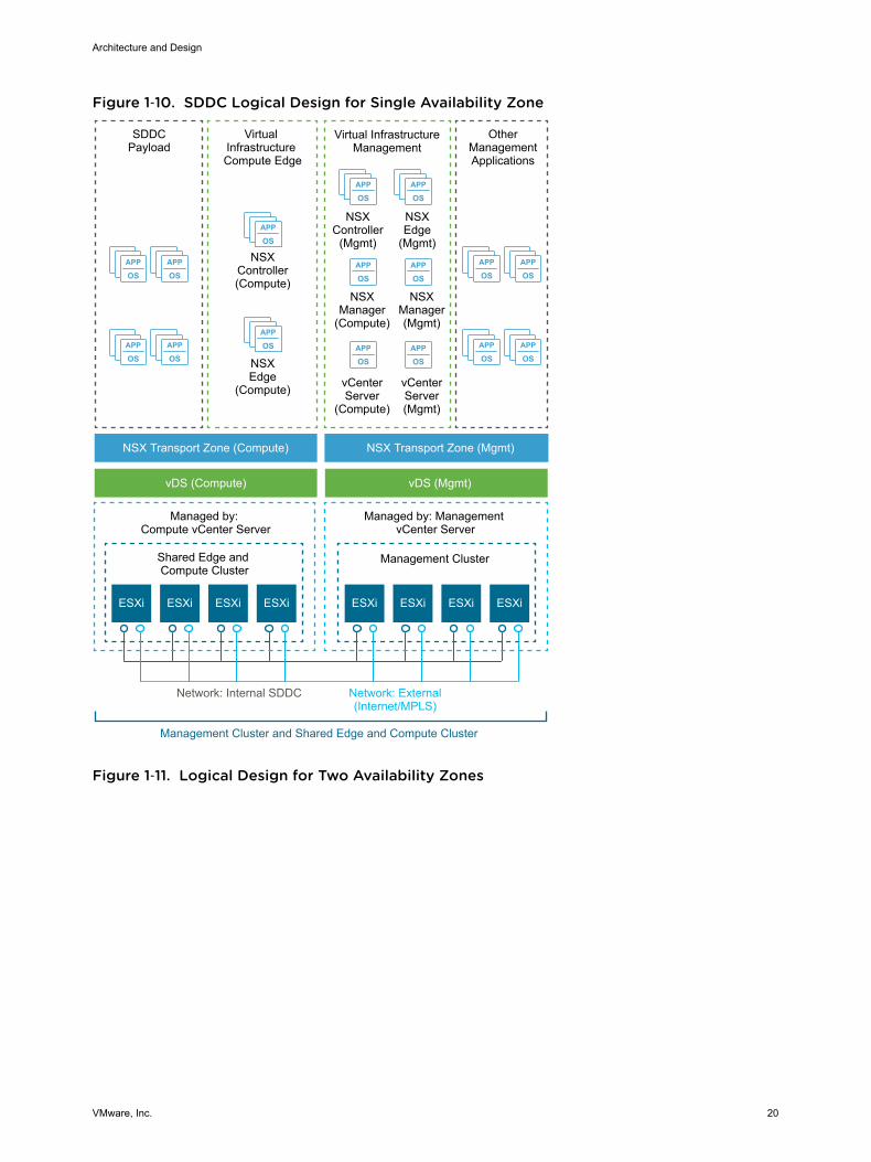
Figure 1‑10. SDDC Logical Design for Single Availability Zone
APP
OSAPP
OS
APP
OSAPP
OS
APP
OSAPP
OS
APP
OSAPP
OS
APP
OS
APP
OS
APP
OSAPP
OS
APP
OSAPP
OS
APP
OSAPP
OS
Virtual InfrastructureManagement
NSXController
(Mgmt)
OtherManagementApplications
NSXEdge
(Mgmt)
NSXManager(Mgmt)
NSXManager
(Compute)
NSXEdge
(Compute)
NSXController(Compute)
ESXi ESXi ESXi ESXi ESXi ESXi
SDDCPayload
Virtual Infrastructure Compute Edge
NSX Transport Zone (Compute)
vDS (Compute) vDS (Mgmt)
NSX Transport Zone (Mgmt)
Shared Edge and Compute Cluster
Management Cluster
Managed by: Compute vCenter Server
Managed by: Management vCenter Server
Network: External(Internet/MPLS)
Network: Internal SDDC
Management Cluster and Shared Edge and Compute Cluster
vCenterServer(Mgmt)
vCenterServer
(Compute)
ESXiESXi
Figure 1‑11. Logical Design for Two Availability Zones
Architecture and Design
VMware, Inc. 20

APP
OS
APP
OSAPP
OSAPP
OS
APP
OSAPP
OS
APP
OS
APP
OS
APP
OSAPP
OS
APP
OS
APP
OS
APP
OS
APP
OSAPP
OS
APP
OSAPP
OS
APP
OS
APP
OS
APP
OS
APP
OSAPP
OSAPP
OSAPP
OS
ESXi ESXi
Virtual InfrastructureCompute Edge
NSXPrimary Edge
(Compute)
NSXController(Compute)
ESXi
SDDC Payload
NSX Transport Zone (Compute)
vDS (Compute)
Stretched Shared Edge and Compute Cluster
Stretched Management Cluster
Managed by: Compute vCenter
Server
Managed by: Management vCenter Server
External Network (Internet/MPLS/DC Interconnect)
Availability Zone InternalSDDC Fabrics
Availability Zone 1 - Management and Shared Edge and Compute Clusters
ESXi
Virtual InfrastructureManagement
NSXController
(Mgmt)
NSXPrimary Edge
(Mgmt)
NSXManager(Mgmt)
NSXManager
(Compute)
vCenterServer(Mgmt)
vCenterServer
(Compute)
Availability Zone 2 (Secondary) - Management and Shared Edge and Compute Clusters
OtherManagementApplications
ESXiESXi ESXiESXi
ESXiESXi ESXiESXiESXiESXi ESXiESXi
NSX Transport Zone (Compute)
vDS (Compute)
NSX Transport Zone (Mgmt)
vDS (Mgmt)
NSX Transport Zone (Mgmt)
vDS (Mgmt)
Virtual InfrastructureCompute Edge
NSXSecondary Edge
(Compute)
SDDC Payload Virtual InfrastructureManagement
NSXSecondary Edge
(Mgmt)
OtherManagementApplications
Architecture and Design
VMware, Inc. 21
Management ClusterThe management cluster runs the virtual machines that manage the SDDC. These virtual machines hostvCenter Server, vSphere Update Manager, NSX Manager, NSX Controllers, vRealize OperationsManager, vRealize Log Insight, vRealize Automation, Site Recovery Manager, and other managementcomponents. All management, monitoring, and infrastructure services are provisioned to a vSpherecluster which provides high availability for these critical services. Permissions on the management clusterlimit access only to administrators. This limitation protects the virtual machines that are running themanagement, monitoring, and infrastructure services from unauthorized access.
Shared Edge and Compute ClusterThe shared edge and compute cluster runs the following components:
n NSX services that are required for north-south routing between the SDDC tenant workloads and theexternal network, and east-west routing in the SDDC.
n Tenant workloads.
As the SDDC expands, you can add more compute-only clusters to support a mix of different types ofworkloads for different types of SLAs.
Network Virtualization Components VMware NSX for vSphere creates the network virtualization layer in the SDDC architecture. The NSX forvSphere platform consists of several components that are relevant to the network virtualization design.
NSX for vSphere PlatformAll virtual networks are created on top of the network virtualization layer, which is an abstraction betweenthe physical and virtual networks. Creating this network virtualization layer requires the followingcomponents:
n vCenter Server
n NSX Manager
n NSX Controllers
n NSX logical switch
Architecture and Design
VMware, Inc. 22
These components are separated in different planes to create communications boundaries and provideisolation of workload data from system control messages.
Data plane The data plane handles the workload data only. NSX logical switchessegregate unrelated workload data. The data is carried over designatedtransport networks in the physical network. NSX logical switch, distributedrouting, and distributed firewall are also implemented in the data plane.
Control plane The control plane handles network virtualization control messages. Controlmessages are used to set up networking attributes on NSX logical switchinstances, and to configure and manage disaster recovery and distributedfirewall components on each ESXi host. Carry over control planecommunication on secure physical networks (VLANs) that are isolated fromthe transport networks used for the data plane.
Management plane The network virtualization orchestration occurs in the management plane.In this layer, cloud management platforms such as vRealize Automationcan request, consume, and destroy networking resources for virtualworkloads. The cloud management platform directs requests to vCenterServer to create and manage virtual machines, and to NSX Manager toconsume networking resources.
Network Virtualization Services Network virtualization services include logical switches, logical routers, logical firewalls, and othercomponents of NSX for vSphere.
Logical SwitchesNSX logical switches create logically abstracted segments to which tenant virtual machines can connect.A single logical switch is mapped to a unique VXLAN segment ID and is distributed across the ESXihypervisors within a transport zone. This logical switch configuration provides support for line-rateswitching in the hypervisor without creating constraints of VLAN sprawl or spanning tree issues.
Universal Distributed Logical RouterUniversal distributed logical router (UDLR) in NSX for vSphere performs routing operations in thevirtualized space (between VMs, on VXLAN- or VLAN-backed port groups). UDLR has the followingfeatures:
n High performance, low overhead first hop routing
n Scaling the number of hosts
n Support for up to 1,000 logical interfaces (LIFs) on each distributed logical router
Architecture and Design
VMware, Inc. 23
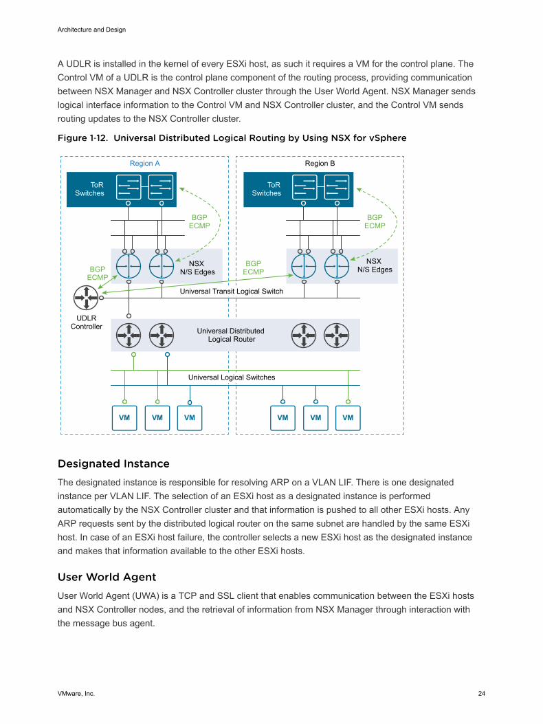
A UDLR is installed in the kernel of every ESXi host, as such it requires a VM for the control plane. TheControl VM of a UDLR is the control plane component of the routing process, providing communicationbetween NSX Manager and NSX Controller cluster through the User World Agent. NSX Manager sendslogical interface information to the Control VM and NSX Controller cluster, and the Control VM sendsrouting updates to the NSX Controller cluster.
Figure 1‑12. Universal Distributed Logical Routing by Using NSX for vSphere
Region A
Universal Transit Logical Switch
Universal Distributed Logical Router
Universal Logical Switches
NSX N/S Edges
UDLRController
BGPECMP
BGPECMPBGP
ECMP
NSX N/S Edges
BGPECMP
Region B
ToRSwitches
ToRSwitches
Designated InstanceThe designated instance is responsible for resolving ARP on a VLAN LIF. There is one designatedinstance per VLAN LIF. The selection of an ESXi host as a designated instance is performedautomatically by the NSX Controller cluster and that information is pushed to all other ESXi hosts. AnyARP requests sent by the distributed logical router on the same subnet are handled by the same ESXihost. In case of an ESXi host failure, the controller selects a new ESXi host as the designated instanceand makes that information available to the other ESXi hosts.
User World AgentUser World Agent (UWA) is a TCP and SSL client that enables communication between the ESXi hostsand NSX Controller nodes, and the retrieval of information from NSX Manager through interaction withthe message bus agent.
Architecture and Design
VMware, Inc. 24
Edge Services GatewayWhile the UDLR provides VM-to-VM or east-west routing, the NSX Edge services gateway providesNorth-South connectivity, by peering with upstream top of rack switches, thereby enabling tenants toaccess public networks.
Logical FirewallNSX Logical Firewall provides security mechanisms for dynamic virtual data centers.
n The Distributed Firewall allows you to segment virtual data center entities like virtual machines.Segmentation can be based on VM names and attributes, user identity, vCenter Server objects likedata centers, and ESXi hosts, or can be based on traditional networking attributes like IPaddresses, port groups, and so on.
n The Edge Firewall component helps you meet important perimeter security requirements, such asbuilding DMZs based on IP/VLAN constructs, tenant-to-tenant isolation in multi-tenant virtual datacenters, Network Address Translation (NAT), partner (extranet) VPNs, and user-based SSL VPNs.
The Flow Monitoring feature displays network activity between virtual machines at the application protocollevel. You can use this information to audit network traffic, define and refine firewall policies, and identifythreats to your network.
Logical Virtual Private Networks (VPNs)SSL VPN-Plus allows remote users to access private corporate applications. IPSec VPN offers site-to-siteconnectivity between an NSX Edge instance and remote sites. L2 VPN allows you to extend yourdatacenter by allowing virtual machines to retain network connectivity across geographical boundaries.
Logical Load BalancerThe NSX Edge load balancer enables network traffic to follow multiple paths to a specific destination. Itdistributes incoming service requests evenly among multiple servers in such a way that the loaddistribution is transparent to users. Load balancing thus helps in achieving optimal resource utilization,improving throughput, reducing response time, and avoiding overload. NSX Edge provides load balancingup to Layer 7.
Service ComposerService Composer helps you provision and assign network and security services to applications in avirtual infrastructure. You map these services to a security group, and the services are applied to thevirtual machines in the security group.
NSX ExtensibilityVMware partners integrate their solutions with the NSX for vSphere platform to enable an integratedexperience across the entire SDDC. Data center operators can provision complex, multi-tier virtualnetworks in seconds, independent of the underlying network topology or components.
Architecture and Design
VMware, Inc. 25
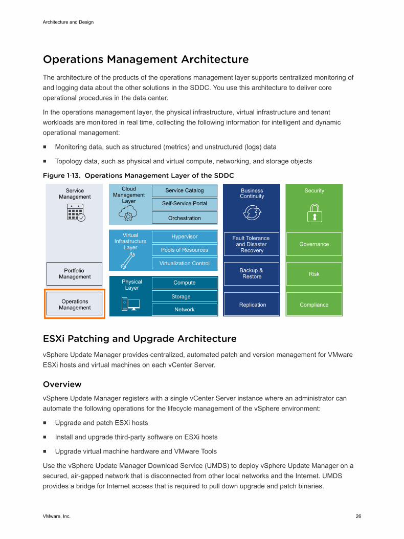
Operations Management Architecture The architecture of the products of the operations management layer supports centralized monitoring ofand logging data about the other solutions in the SDDC. You use this architecture to deliver coreoperational procedures in the data center.
In the operations management layer, the physical infrastructure, virtual infrastructure and tenantworkloads are monitored in real time, collecting the following information for intelligent and dynamicoperational management:
n Monitoring data, such as structured (metrics) and unstructured (logs) data
n Topology data, such as physical and virtual compute, networking, and storage objects
Figure 1‑13. Operations Management Layer of the SDDC
ServiceManagement
Portfolio Management
OperationsManagement
CloudManagement
Layer
Service Catalog
Self-Service Portal
Orchestration
BusinessContinuity
Fault Tolerance and Disaster
Recovery
Backup & Restore
Hypervisor
Pools of Resources
Virtualization Control
VirtualInfrastructure
Layer
Compute
Storage
Network
PhysicalLayer
Security
Replication Compliance
Risk
Governance
ESXi Patching and Upgrade Architecture vSphere Update Manager provides centralized, automated patch and version management for VMwareESXi hosts and virtual machines on each vCenter Server.
OverviewvSphere Update Manager registers with a single vCenter Server instance where an administrator canautomate the following operations for the lifecycle management of the vSphere environment:
n Upgrade and patch ESXi hosts
n Install and upgrade third-party software on ESXi hosts
n Upgrade virtual machine hardware and VMware Tools
Use the vSphere Update Manager Download Service (UMDS) to deploy vSphere Update Manager on asecured, air-gapped network that is disconnected from other local networks and the Internet. UMDSprovides a bridge for Internet access that is required to pull down upgrade and patch binaries.
Architecture and Design
VMware, Inc. 26
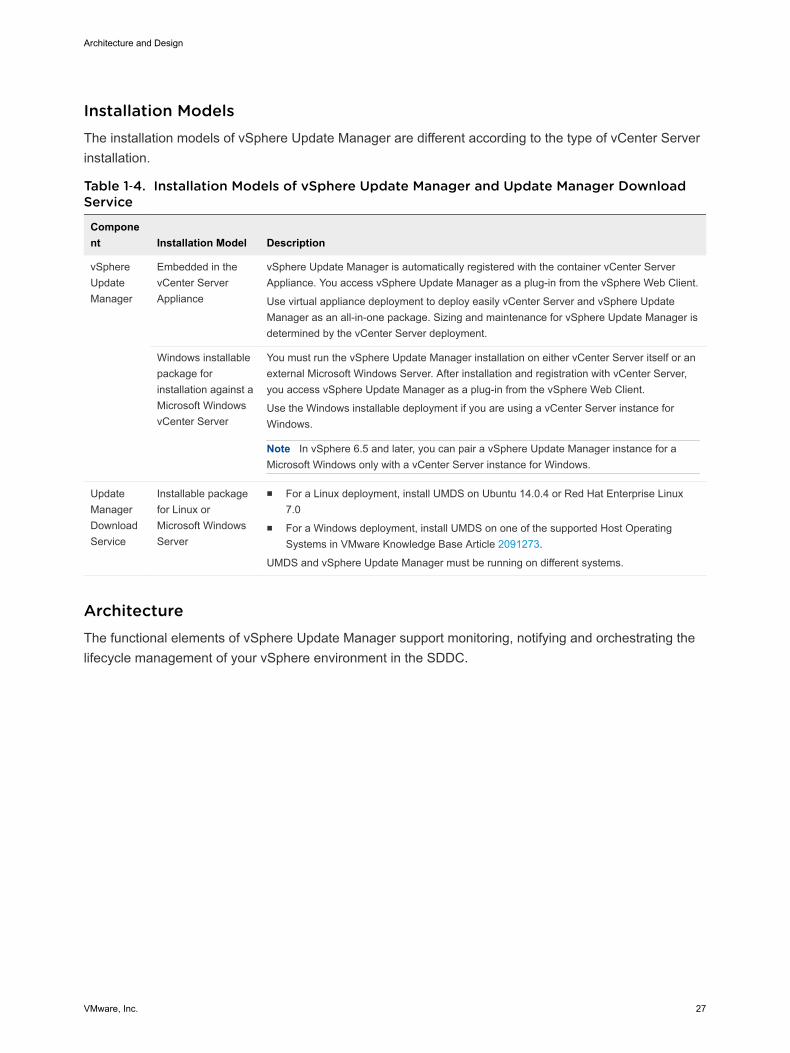
Installation ModelsThe installation models of vSphere Update Manager are different according to the type of vCenter Serverinstallation.
Table 1‑4. Installation Models of vSphere Update Manager and Update Manager DownloadService
Component Installation Model Description
vSphereUpdateManager
Embedded in thevCenter ServerAppliance
vSphere Update Manager is automatically registered with the container vCenter ServerAppliance. You access vSphere Update Manager as a plug-in from the vSphere Web Client.
Use virtual appliance deployment to deploy easily vCenter Server and vSphere UpdateManager as an all-in-one package. Sizing and maintenance for vSphere Update Manager isdetermined by the vCenter Server deployment.
Windows installablepackage forinstallation against aMicrosoft WindowsvCenter Server
You must run the vSphere Update Manager installation on either vCenter Server itself or anexternal Microsoft Windows Server. After installation and registration with vCenter Server,you access vSphere Update Manager as a plug-in from the vSphere Web Client.
Use the Windows installable deployment if you are using a vCenter Server instance forWindows.
Note In vSphere 6.5 and later, you can pair a vSphere Update Manager instance for aMicrosoft Windows only with a vCenter Server instance for Windows.
UpdateManagerDownloadService
Installable packagefor Linux orMicrosoft WindowsServer
n For a Linux deployment, install UMDS on Ubuntu 14.0.4 or Red Hat Enterprise Linux7.0
n For a Windows deployment, install UMDS on one of the supported Host OperatingSystems in VMware Knowledge Base Article 2091273.
UMDS and vSphere Update Manager must be running on different systems.
ArchitectureThe functional elements of vSphere Update Manager support monitoring, notifying and orchestrating thelifecycle management of your vSphere environment in the SDDC.
Architecture and Design
VMware, Inc. 27
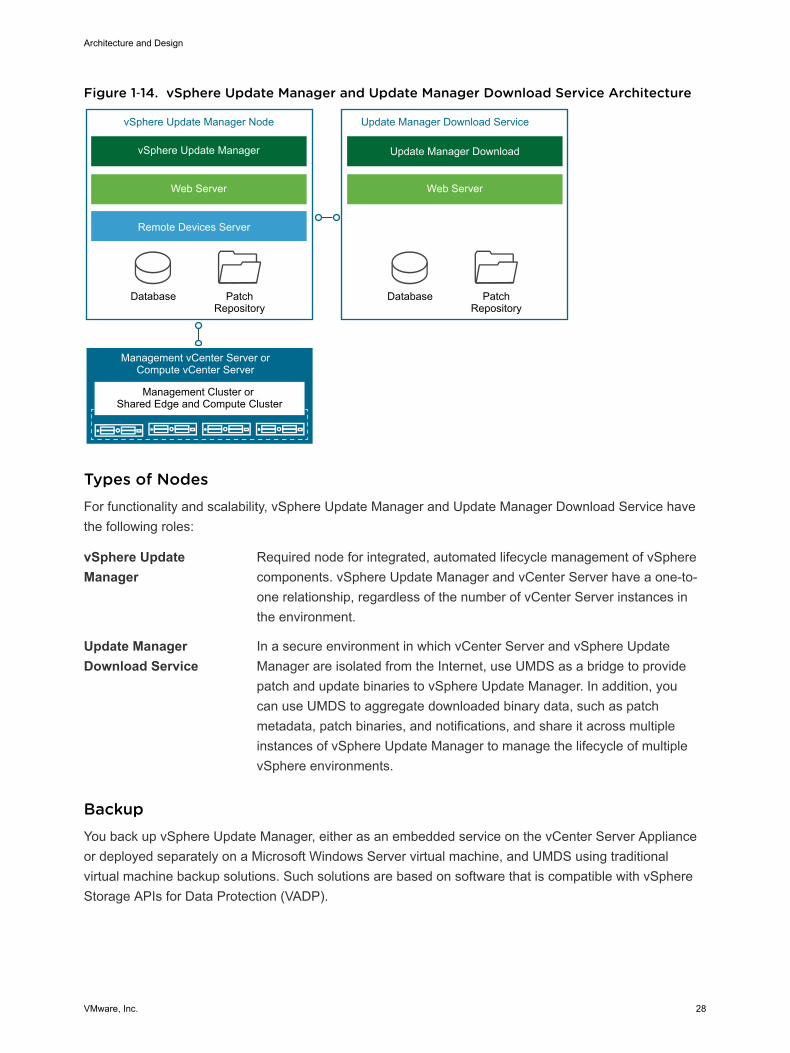
Figure 1‑14. vSphere Update Manager and Update Manager Download Service Architecture
Management Cluster or Shared Edge and Compute Cluster
PatchRepository
PatchRepository
vSphere Update Manager
Web Server
Remote Devices Server
Database
vSphere Update Manager Node
Update Manager Download
Web Server
Database
Update Manager Download Service
Management vCenter Server orCompute vCenter Server
Types of NodesFor functionality and scalability, vSphere Update Manager and Update Manager Download Service havethe following roles:
vSphere UpdateManager
Required node for integrated, automated lifecycle management of vSpherecomponents. vSphere Update Manager and vCenter Server have a one-to-one relationship, regardless of the number of vCenter Server instances inthe environment.
Update ManagerDownload Service
In a secure environment in which vCenter Server and vSphere UpdateManager are isolated from the Internet, use UMDS as a bridge to providepatch and update binaries to vSphere Update Manager. In addition, youcan use UMDS to aggregate downloaded binary data, such as patchmetadata, patch binaries, and notifications, and share it across multipleinstances of vSphere Update Manager to manage the lifecycle of multiplevSphere environments.
BackupYou back up vSphere Update Manager, either as an embedded service on the vCenter Server Applianceor deployed separately on a Microsoft Windows Server virtual machine, and UMDS using traditionalvirtual machine backup solutions. Such solutions are based on software that is compatible with vSphereStorage APIs for Data Protection (VADP).
Architecture and Design
VMware, Inc. 28
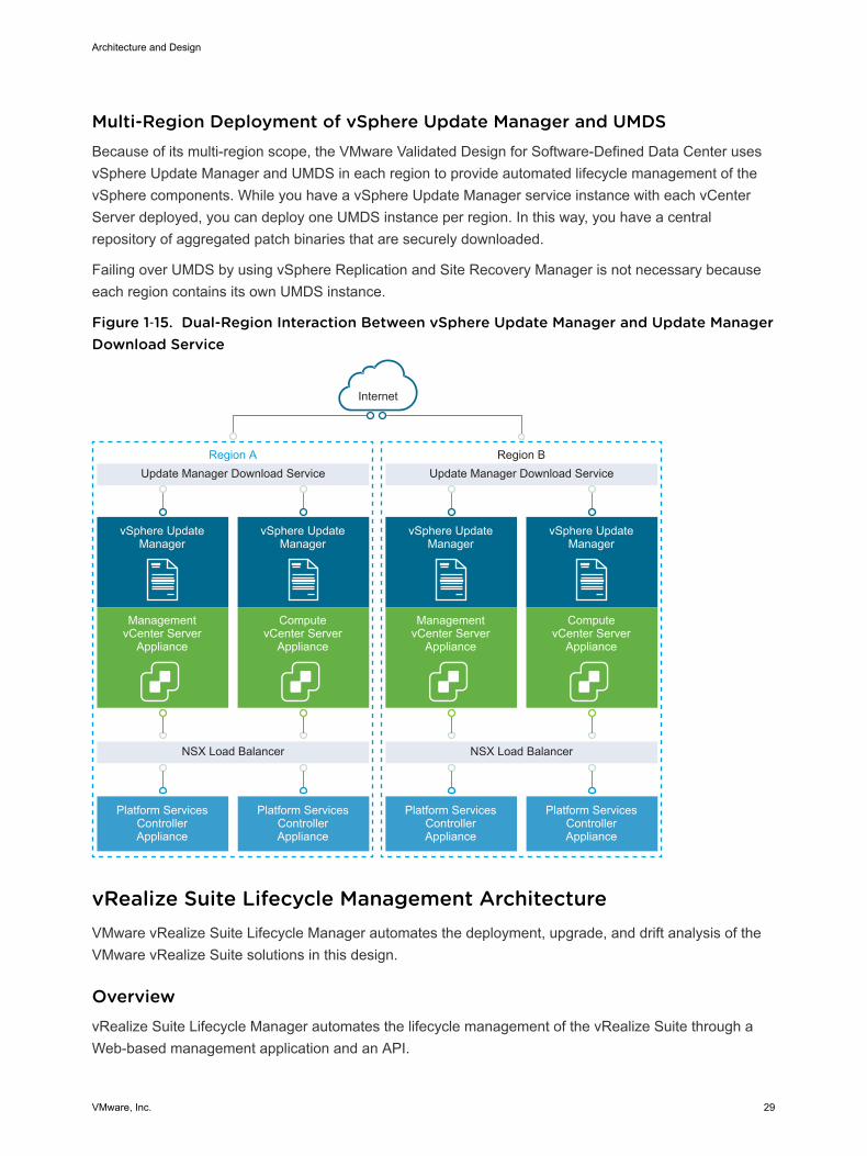
Multi-Region Deployment of vSphere Update Manager and UMDSBecause of its multi-region scope, the VMware Validated Design for Software-Defined Data Center usesvSphere Update Manager and UMDS in each region to provide automated lifecycle management of thevSphere components. While you have a vSphere Update Manager service instance with each vCenterServer deployed, you can deploy one UMDS instance per region. In this way, you have a centralrepository of aggregated patch binaries that are securely downloaded.
Failing over UMDS by using vSphere Replication and Site Recovery Manager is not necessary becauseeach region contains its own UMDS instance.
Figure 1‑15. Dual-Region Interaction Between vSphere Update Manager and Update ManagerDownload Service
Update Manager Download Service
NSX Load Balancer
Platform Services Controller Appliance
Platform Services Controller Appliance
vSphere UpdateManager
ManagementvCenter Server
Appliance
vSphere UpdateManager
ComputevCenter Server
Appliance
Internet
Region AUpdate Manager Download Service
NSX Load Balancer
Platform Services Controller Appliance
Platform Services Controller Appliance
vSphere UpdateManager
ManagementvCenter Server
Appliance
vSphere UpdateManager
ComputevCenter Server
Appliance
Region B
vRealize Suite Lifecycle Management Architecture VMware vRealize Suite Lifecycle Manager automates the deployment, upgrade, and drift analysis of theVMware vRealize Suite solutions in this design.
OverviewvRealize Suite Lifecycle Manager automates the lifecycle management of the vRealize Suite through aWeb-based management application and an API.
Architecture and Design
VMware, Inc. 29
The vRealize Suite Lifecycle Manager solution supports the deployment and upgrade of followingvRealize Suite products:
n vRealize Operations Manager
n vRealize Log Insight
n vRealize Automation (with embedded vRealize Orchestrator)
n vRealize Business for Cloud
DeploymentvRealize Suite Lifecycle Manager is available as a pre-configured virtual appliance in OVA format. Youcan access vRealize Lifecycle Manager using a Web-based application and a REST API.
After you deploy vRealize Suite Lifecycle Manager, you register one or more vCenter Server instanceswith it. Next, an administrator can automate the following operations for the lifecycle management of thevRealize Suite.
Similarly to the vSphere Update Manager Download Service, vRealize Suite Lifecycle Manager providesa bridge for Internet access that is required to download product binaries for install and upgrade from MyVMware and content from the VMware Marketplace.
Lifecycle Management FeaturesvRealize Suite Lifecycle Manager provides the following features for management of multi-productenvironments:
n Manage a vRealize Suite product repository (installation and upgrade).
n Create environments
n Deployment and management of VMware Marketplace content
n Support existing vRealize Suite-based environments.
n Analyze the configuration drift in environments.
n Scale environments out.
n Upgrade environments.
ArchitecturevRealize Suite Lifecycle Manager contains the functional elements that collaborate to orchestrate thelifecycle management operations of the vRealize Suite environment in this VMware Validated Design.
Architecture and Design
VMware, Inc. 30
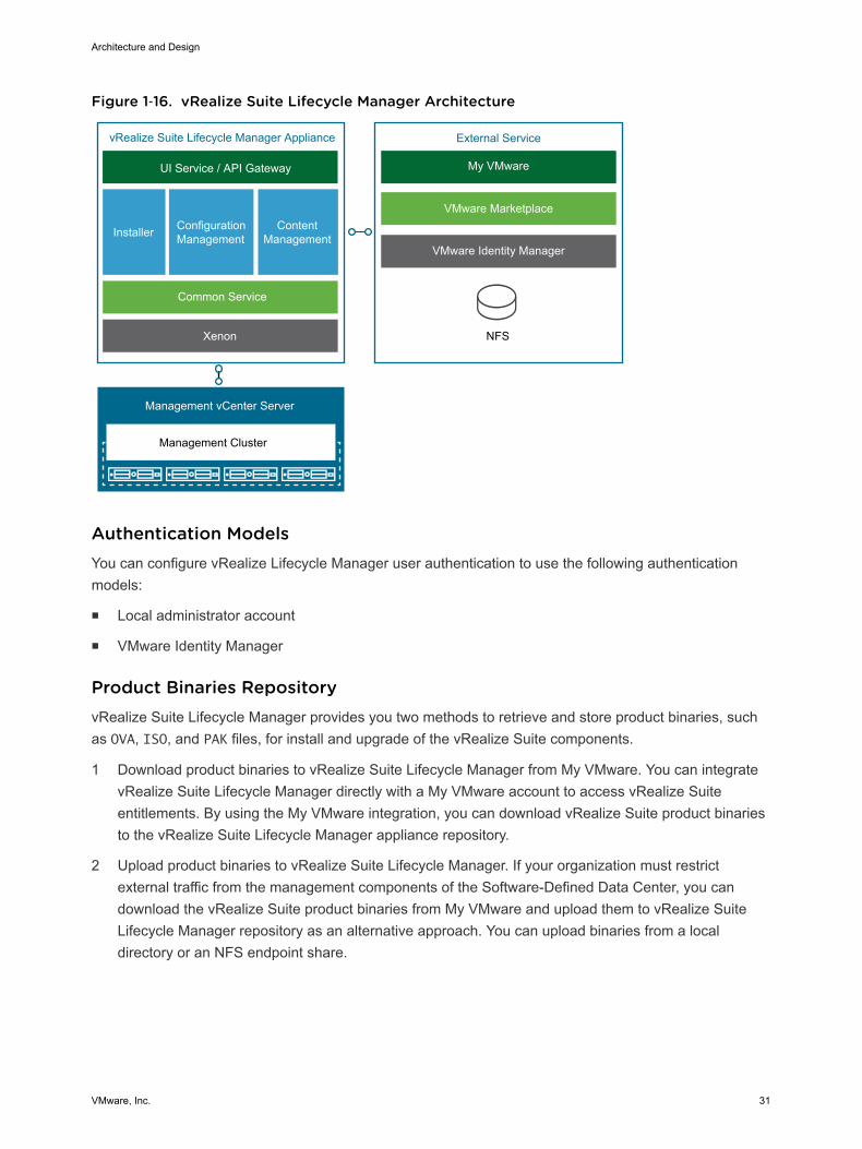
Figure 1‑16. vRealize Suite Lifecycle Manager Architecture
ConfigurationManagementInstaller Content
Management
Management vCenter Server
Xenon NFS
Common Service
UI Service / API Gateway
vRealize Suite Lifecycle Manager Appliance External Service
My VMware
VMware Marketplace
VMware Identity Manager
Management Cluster
Authentication ModelsYou can configure vRealize Lifecycle Manager user authentication to use the following authenticationmodels:
n Local administrator account
n VMware Identity Manager
Product Binaries RepositoryvRealize Suite Lifecycle Manager provides you two methods to retrieve and store product binaries, suchas OVA, ISO, and PAK files, for install and upgrade of the vRealize Suite components.
1 Download product binaries to vRealize Suite Lifecycle Manager from My VMware. You can integratevRealize Suite Lifecycle Manager directly with a My VMware account to access vRealize Suiteentitlements. By using the My VMware integration, you can download vRealize Suite product binariesto the vRealize Suite Lifecycle Manager appliance repository.
2 Upload product binaries to vRealize Suite Lifecycle Manager. If your organization must restrictexternal traffic from the management components of the Software-Defined Data Center, you candownload the vRealize Suite product binaries from My VMware and upload them to vRealize SuiteLifecycle Manager repository as an alternative approach. You can upload binaries from a localdirectory or an NFS endpoint share.
Architecture and Design
VMware, Inc. 31
Marketplace IntegrationBy using vRealize Suite Lifecycle Manager, you can deploy vRealize Operations management packs,vRealize Log Insight content packs, and vRealize Automation blueprints and OVA files directly from theVMware Marketplace.
BackupThe vRealize Suite Lifecycle Manager virtual appliance is backed up using traditional virtual machinebackup solutions that are compatible with VMware vSphere Storage APIs – Data Protection (VADP).
Multi-Region Deployment of vRealize Suite Lifecycle ManagerThe scope of this design can cover both single region, multiple regions, and availability zones.
In a multi-region implementation, VMware Validated Design for Software-Defined Data Center implementsa vRealize Suite Lifecycle Manager setup in multiple regions by using the following configuration:
n A single vRealize Suite Lifecycle Manager virtual appliance is replicated by vSphere Replication andrecovered by Site Recovery Manager so that you can fail it over across regions in the event ofplanned migration or disaster recovery event.
n The vRealize Suite Lifecycle Manager instance manages the deployment, upgrade, and configurationdrift analysis of the vRealize products across all regions.
In a multi-availability zone implementation, which is a subset of the multi-region design, vRealize SuiteLifecycle Manager continues to provide lifecycle services for the vRealize Suite based deployments in allregions of the SDDC. The virtual appliance of vRealize Suite Lifecycle Manager resides in AvailabilityZone 1 in Region A. If this zone becomes compromised, the instance it brought back online in AvailabilityZone 2.
Monitoring Architecture vRealize Operations Manager tracks and analyzes the operation of multiple data sources in the SDDC byusing specialized analytic algorithms. These algorithms help vRealize Operations Manager learn andpredict the behavior of every object it monitors. Users access this information by using views, reports, anddashboards.
DeploymentvRealize Operations Manager is available as a pre-configured virtual appliance in OVF. By using thevirtual appliance, you can easily create vRealize Operations Manager nodes with pre-defined identicalsizes.
You deploy the OVF file of the virtual appliance once for each node. After node deployment, you accessthe product to set up cluster nodes according to their role and log in to configure the installation.
Architecture and Design
VMware, Inc. 32
Deployment ModelsYou can deploy vRealize Operations Manager as a virtual appliance in one of the following configurations:
n Standalone node
n Cluster of one master and at least one data node, and optionally a group of remote collector nodes.
You can establish high availability by using an external load balancer.
The compute and storage resources of the vRealize Log Insight instances can scale up as growthdemands.
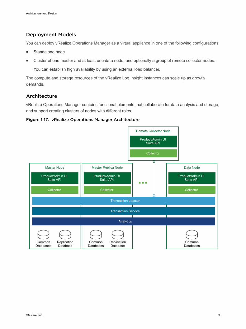
ArchitecturevRealize Operations Manager contains functional elements that collaborate for data analysis and storage,and support creating clusters of nodes with different roles.
Figure 1‑17. vRealize Operations Manager Architecture
Remote Collector Node
Product/Admin UISuite API
Collector
Master Node
Product/Admin UISuite API
CommonDatabases
ReplicationDatabase
Collector
Data Node
Product/Admin UISuite API
CommonDatabases
Collector
Master Replica Node
Product/Admin UISuite API
CommonDatabases
ReplicationDatabase
Collector
Transaction Locator
Transaction Service
Analytics
Architecture and Design
VMware, Inc. 33
Types of NodesFor high availability and scalability, you can deploy several vRealize Operations Manager instances in acluster to track, analyze, and predict the operation of monitored systems. Cluster nodes can have eitherof the following roles.
Master Node Required initial node in the cluster. In large-scale environments, managesall other nodes. In small-scale environments, the master node is the singlestandalone vRealize Operations Manager node.
Master Replica Node Optional. Enables high availability of the master node.
Data Node Optional. Enables scale-out of vRealize Operations Manager in largerenvironments. Data nodes have adapters installed to perform collection andanalysis. Data nodes also host vRealize Operations Manager managementpacks.
Remote Collector Node Overcomes data collection issues across the enterprise network, such aslimited network performance. You can also use remote collector nodes tooffload data collection from the other types of nodes.
Remote collector nodes only gather statistics about inventory objects andforward collected data to the data nodes. Remote collector nodes do notstore data or perform analysis.
The master and master replica nodes are data nodes that have extended capabilities.
Types of Node Groups
Analytics Cluster Tracks, analyzes, and predicts the operation of monitored systems.Consists of a master node, data nodes, and optionally of a master replicanode.
Remote CollectorGroup
Because it consists of remote collector nodes, only collects diagnosticsdata without storage or analysis. A vRealize Operations Managerdeployment can contain several collector groups.
Use collector groups to achieve adapter resiliency in cases where thecollector experiences network interruption or becomes unavailable.
Application Functional Components The functional components of a vRealize Operations Manager instance interact with each other toanalyze diagnostics data from the data center and visualize the result in the Web user interface.
Architecture and Design
VMware, Inc. 34
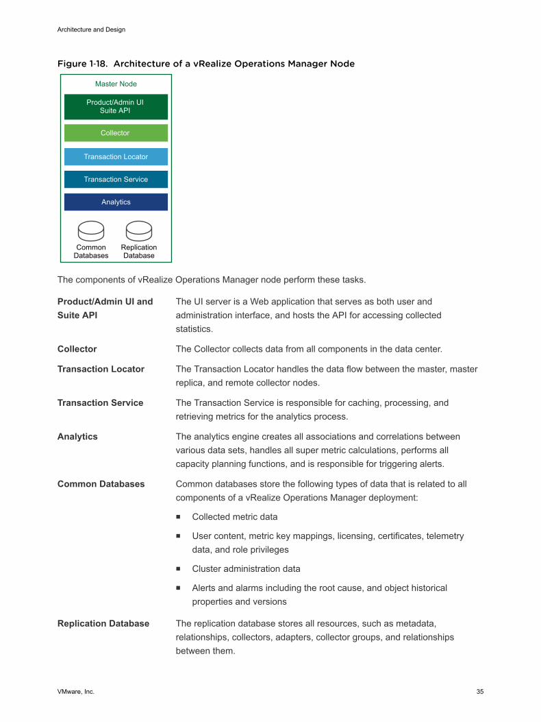
Figure 1‑18. Architecture of a vRealize Operations Manager Node
Master Node
Product/Admin UISuite API
CommonDatabases
ReplicationDatabase
Collector
Transaction Locator
Transaction Service
Analytics
The components of vRealize Operations Manager node perform these tasks.
Product/Admin UI andSuite API
The UI server is a Web application that serves as both user andadministration interface, and hosts the API for accessing collectedstatistics.
Collector The Collector collects data from all components in the data center.
Transaction Locator The Transaction Locator handles the data flow between the master, masterreplica, and remote collector nodes.
Transaction Service The Transaction Service is responsible for caching, processing, andretrieving metrics for the analytics process.
Analytics The analytics engine creates all associations and correlations betweenvarious data sets, handles all super metric calculations, performs allcapacity planning functions, and is responsible for triggering alerts.
Common Databases Common databases store the following types of data that is related to allcomponents of a vRealize Operations Manager deployment:
n Collected metric data
n User content, metric key mappings, licensing, certificates, telemetrydata, and role privileges
n Cluster administration data
n Alerts and alarms including the root cause, and object historicalproperties and versions
Replication Database The replication database stores all resources, such as metadata,relationships, collectors, adapters, collector groups, and relationshipsbetween them.
Architecture and Design
VMware, Inc. 35
Authentication SourcesYou can configure vRealize Operations Manager user authentication to use one or more of the followingauthentication sources:
n vCenter Single Sign-On
n VMware Identity Manager
n OpenLDAP via LDAP
n Active Directory via LDAP
Management PacksManagement packs contain extensions and third-party integration software. They add dashboards, alertdefinitions, policies, reports, and other content to the inventory of vRealize Operations Manager. You canlearn more details about and download management packs from VMware Solutions Exchange.
BackupYou back up each vRealize Operations Manager node using traditional virtual machine backup solutionsthat are compatible with VMware vSphere Storage APIs – Data Protection (VADP).
Multi-Region vRealize Operations Manager DeploymentThe scope of this validated design can cover both multiple regions and availability zones.
VMware Validated Design for Software-Defined Data Center implements a large-scale vRealizeOperations Manager deployment across multiple regions by using the following configuration:
n Load-balanced analytics cluster that runs multiple nodes is protected by Site Recovery Manager tofail over across regions
n Multiple remote collector nodes that are assigned to a remote collector group in each region to handledata coming from management solutions
In a multi-availability zone implementation, which is a super-set of the multi-region design, vRealizeOperations Manager continues to provide monitoring of the solutions in all regions of the SDDC. Allcomponents of vRealize Operations Manager reside in Availability Zone 1 in Region A. If this zonebecomes compromised, all nodes are brought up in Availability Zone 2.
Logging Architecture vRealize Log Insight provides real-time log management and log analysis with machine learning-basedintelligent grouping, high-performance searching, and troubleshooting across physical, virtual, and cloudenvironments.
Architecture and Design
VMware, Inc. 36
OverviewvRealize Log Insight collects data from ESXi hosts using the syslog protocol. vRealize Log Insight has thefollowing capabilities:
n Connects to other VMware products, like vCenter Server, to collect events, tasks, and alarm data.
n Integrates with vRealize Operations Manager to send notification events and enable launch incontext.
n Functions as a collection and analysis point for any system that is capable of sending syslog data.
To collect additional logs, you can install an ingestion agent on Linux or Windows servers, or you can usethe pre-installed agent on certain VMware products. Using pre-installed agents is useful for customapplication logs and operating systems that do not natively support the syslog protocol, such as Windows.
DeploymentvRealize Log Insight is available as a pre-configured virtual appliance in OVF. By using the virtualappliance, you can easily create vRealize Log Insight nodes with pre-defined identical sizes.
You deploy the OVF file of the virtual appliance once for each node. After node deployment, you accessthe product to set up cluster nodes according to their role and log in to configure the installation.
Deployment ModelsYou can deploy vRealize Log Insight as a virtual appliance in one of the following configurations:
n Standalone node
n Cluster of one master and at least two worker nodes. You can establish high availability by using theintegrated load balancer (ILB).
The compute and storage resources of the vRealize Log Insight instances can scale-up as growthdemands.
ArchitectureThe architecture of vRealize Log Insight in the SDDC enables several channels for the collection of logmessages.
Architecture and Design
VMware, Inc. 37
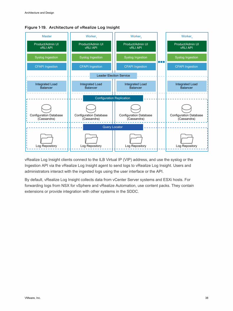
Figure 1‑19. Architecture of vRealize Log Insight
Master
Product/Admin UIvRLI API
Integrated Load Balancer
Configuration Database(Cassandra)
Log Repository
Leader Election Service
Configuration Replication
Query Locator
Syslog Ingestion
CFAPI Ingestion
Worker1
Product/Admin UIvRLI API
Integrated Load Balancer
Configuration Database(Cassandra)
Log Repository
Syslog Ingestion
CFAPI Ingestion
Worker2
Product/Admin UIvRLI API
Integrated Load Balancer
Configuration Database(Cassandra)
Log Repository
Syslog Ingestion
CFAPI Ingestion
Workern
Product/Admin UIvRLI API
Integrated Load Balancer
Configuration Database(Cassandra)
Log Repository
Syslog Ingestion
CFAPI Ingestion
vRealize Log Insight clients connect to the ILB Virtual IP (VIP) address, and use the syslog or theIngestion API via the vRealize Log Insight agent to send logs to vRealize Log Insight. Users andadministrators interact with the ingested logs using the user interface or the API.
By default, vRealize Log Insight collects data from vCenter Server systems and ESXi hosts. Forforwarding logs from NSX for vSphere and vRealize Automation, use content packs. They containextensions or provide integration with other systems in the SDDC.
Architecture and Design
VMware, Inc. 38
Types of NodesFor functionality, high availability and scalability, vRealize Log Insight supports the following types ofnodes which have inherent roles:
Master Node Required initial node in the cluster. In standalone mode, the master node isresponsible for all activities, including queries and log ingestion. The masternode also handles operations that are related to the lifecycle of a cluster,such as performing upgrades and addition or removal of worker nodes. In ascaled-out and highly available environment, the master node still performslifecycle operations such as addition or removal of worker nodes. However,it functions as a generic worker about queries and log ingestion activities.
The master node stores logs locally. If the master node is down, the logsstored on it become unavailable.
Worker Node Optional. This component enables scale-out in larger environments. As youadd and configure more worker nodes in a vRealize Log Insight cluster forhigh availability (HA), queries and log ingestion activities are delegated toall available nodes. You must have at least two worker nodes to form acluster with the master node.
The worker node stores logs locally. If any of the worker nodes is down, thelogs on the worker become unavailable.
Integrated LoadBalancer (ILB)
In cluster mode, the ILB is the centralized entry point which ensures thatvRealize Log Insight accepts incoming ingestion traffic. As nodes areadded to the vRealize Log Insight instance to form a cluster, the ILB featuresimplifies the configuration for high availability. The ILB balances theincoming traffic fairly among the available vRealize Log Insight nodes.
The ILB runs on one of the cluster nodes at all times. In environments thatcontain several nodes, an election process determines the leader of thecluster. Periodically, the ILB performs a health check to determine whetherre-election is required. If the node that hosts the ILB Virtual IP (VIP)address stops responding, the VIP address is failed over to another node inthe cluster via an election process.
All queries against data are directed to the ILB. The ILB delegates queriesto a query master for the duration of the query. The query master queries allnodes, both master and worker nodes, for data and then sends theaggregated data back to the client.
Use the ILB for administrative activities unless you are performingadministrative activities on individual nodes. The Web user interface of theILB presents data from the master and from the worker nodes in a scaled-out cluster in a unified display(single pane of glass).
Architecture and Design
VMware, Inc. 39
Application Functional ComponentsThe functional components of a vRealize Log Insight instance interact with each other to perform thefollowing operations:
n Analyze logging data that is ingested from the components of a data center
n Visualize the results in a Web browser, or support results query using API calls.
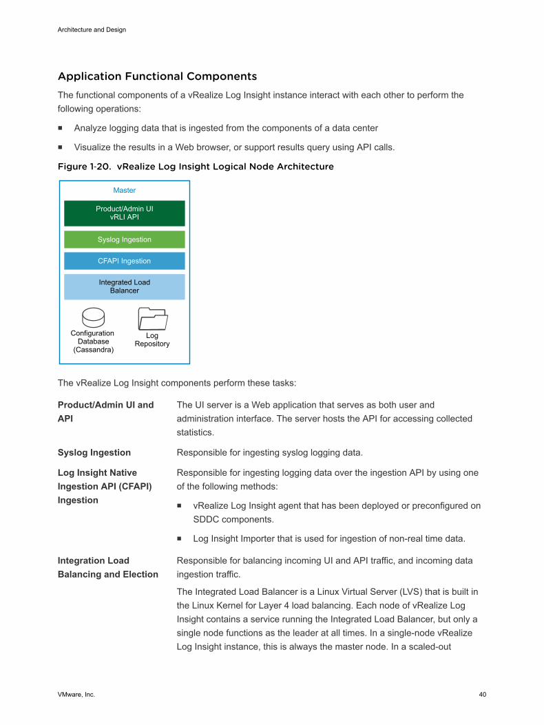
Figure 1‑20. vRealize Log Insight Logical Node Architecture
Master
Product/Admin UIvRLI API
Integrated Load Balancer
Configuration Database
(Cassandra)
LogRepository
Syslog Ingestion
CFAPI Ingestion
The vRealize Log Insight components perform these tasks:
Product/Admin UI andAPI
The UI server is a Web application that serves as both user andadministration interface. The server hosts the API for accessing collectedstatistics.
Syslog Ingestion Responsible for ingesting syslog logging data.
Log Insight NativeIngestion API (CFAPI)Ingestion
Responsible for ingesting logging data over the ingestion API by using oneof the following methods:
n vRealize Log Insight agent that has been deployed or preconfigured onSDDC components.
n Log Insight Importer that is used for ingestion of non-real time data.
Integration LoadBalancing and Election
Responsible for balancing incoming UI and API traffic, and incoming dataingestion traffic.
The Integrated Load Balancer is a Linux Virtual Server (LVS) that is built inthe Linux Kernel for Layer 4 load balancing. Each node of vRealize LogInsight contains a service running the Integrated Load Balancer, but only asingle node functions as the leader at all times. In a single-node vRealizeLog Insight instance, this is always the master node. In a scaled-out
Architecture and Design
VMware, Inc. 40
vRealize Log Insight cluster, this role can be inherited by any of theavailable nodes during the election process. The leader periodicallyperforms health checks to determine whether a re-election process isrequired for the cluster.
Configuration Database Stores configuration information about the vRealize Log Insight nodes andcluster. The information that is stored in the database is periodicallyreplicated to all available vRealize Log Insight nodes.
Log Repository Stores logging data that is ingested in vRealize Log Insight. The loggingrepository is local to each node and not replicated. If a node is offline orremoved, the logging data which is stored on that node becomesinaccessible. In environments where an ILB is configured, incoming loggingdata is evenly distributed across all available nodes.
When a query arrives from the ILB, the vRealize Log Insight node holdingthe ILB leader role delegates the query to any of the available nodes in thecluster.
Authentication ModelsYou can configure vRealize Log Insight user authentication to utilize one or more of the followingauthentication models:
n Microsoft Active Directory
n Local Accounts
n VMware Identity Manager
Content PacksContent packs help add valuable troubleshooting information in to vRealize Log Insight. They providestructure and meaning to raw logging data that is collected from either a vRealize Log Insight agent,vRealize Log Insight Importer or a syslog stream. They add vRealize Log Insight agent configurations,providing out-of-the-box parsing capabilities for standard logging directories and logging formats, alongwith dashboards, extracted fields, alert definitions, query lists, and saved queries from the logging datarelated to a specific product in vRealize Log Insight. Visit Log Insight Content Pack Marketplace or theVMware Solutions Exchange.
Integration with vRealize Operations ManagerThe integration of vRealize Log Insight with vRealize Operations Manager provides data from multiplesources to a central place for monitoring the SDDC. The integration has the following advantages:
n vRealize Log Insight sends notification events to vRealize Operations Manager.
Architecture and Design
VMware, Inc. 41
n vRealize Operations Manager can provide the inventory map of any vSphere object to vRealize LogInsight. In this way, you can view log messages from vRealize Log Insight in the vRealize OperationsManager Web user interface, taking you either directly to the object itself or to the location of theobject within the environment.
n Access to the vRealize Log Insight user interface is embedded in the vRealize Operations Manageruser interface .
ArchivingvRealize Log Insight supports data archiving on an NFS shared storage that the vRealize Log Insightnodes can access. However, vRealize Log Insight does not manage the NFS mount used for archivingpurposes. vRealize Log Insight also does not perform cleanup of the archival files.
The NFS mount for archiving can run out of free space or become unavailable for a period of time greaterthan the retention period of the virtual appliance. In that case, vRealize Log Insight stops ingesting newdata until the NFS mount has enough free space or becomes available, or until archiving is disabled. Ifarchiving is enabled, system notifications from vRealize Log Insight sends you an email when the NFSmount is about to run out of space or is unavailable.
BackupYou back up each vRealize Log Insight cluster using traditional virtual machine backup solutions that arecompatible with VMware vSphere Storage APIs – Data Protection (VADP).
Multi-Region vRealize Log Insight DeploymentThe scope of this validated design can cover both multiple regions and availability zones.
In a multi-region implementation, vRealize Log Insight provides a separate logging infrastructure in eachregion of the SDDC. Using vRealize Log Insight across multiple regions requires the followingconfiguration:
n Cluster in each region.
n Event forwarding to other vRealize Log Insight deployments across regions in the SDDC.
In a multi-availabilty zone implementation, which is a sub-set of the multi-region design, vRealize Loginsight continues to provide a logging infrastructure in all regions of the SDDC. All components of thevRealize Log Insight cluster reside in Availability Zone 1 within Region A. If this zone becomescompromised, all nodes are brought up in the Availability Zone 2.
Failover by using vSphere Replication or disaster recovery by using Site Recovery Manager is notnecessary. The event forwarding feature adds tags to log messages that identify the source region. Eventfiltering prevents looping messages between the regions.
Architecture and Design
VMware, Inc. 42
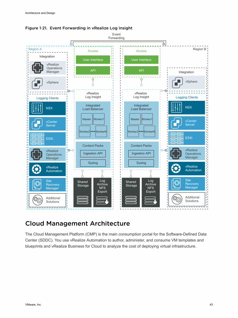
Figure 1‑21. Event Forwarding in vRealize Log Insight
Region A
EventForwarding
Integration
IntegratedLoad Balancer
vSphere
Access
User Interface
API
vRealizeOperationsManager
Content Packs
Syslog
Ingestion API
IntegratedLoad Balancer
Content Packs
Syslog
Ingestion API
Shared Storage
LogArchive
NFSExport
Region B
vRealize Log Insight
vRealize Log Insight
Integration
vSphere
Access
User Interface
API
vRealizeOperationsManager
Logging Clients
vCenter Server
ESXi
NSX
vRealizeAutomation
AdditionalSolutions
Shared Storage
LogArchive
NFSExport
Master Worker1
Worker2 WorkerN
Master Worker1
Worker2 WorkerN
SiteRecoveryManager
vRealizeOperationsManager
Logging Clients
vCenter Server
ESXi
NSX
vRealizeAutomation
AdditionalSolutions
SiteRecoveryManager
Cloud Management Architecture The Cloud Management Platform (CMP) is the main consumption portal for the Software-Defined DataCenter (SDDC). You use vRealize Automation to author, administer, and consume VM templates andblueprints and vRealize Business for Cloud to analyze the cost of deploying virtual infrastructure.
Architecture and Design
VMware, Inc. 43
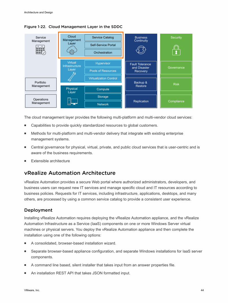
Figure 1‑22. Cloud Management Layer in the SDDC
ServiceManagement
Portfolio Management
OperationsManagement
CloudManagement
Layer
Service Catalog
Self-Service Portal
Orchestration
BusinessContinuity
Fault Tolerance and Disaster
Recovery
Backup & Restore
Hypervisor
Pools of Resources
Virtualization Control
VirtualInfrastructure
Layer
Compute
Storage
Network
PhysicalLayer
Security
Replication Compliance
Risk
Governance
The cloud management layer provides the following multi-platform and multi-vendor cloud services:
n Capabilities to provide quickly standardized resources to global customers.
n Methods for multi-platform and multi-vendor delivery that integrate with existing enterprisemanagement systems.
n Central governance for physical, virtual, private, and public cloud services that is user-centric and isaware of the business requirements.
n Extensible architecture
vRealize Automation Architecture vRealize Automation provides a secure Web portal where authorized administrators, developers, andbusiness users can request new IT services and manage specific cloud and IT resources according tobusiness policies. Requests for IT services, including infrastructure, applications, desktops, and manyothers, are processed by using a common service catalog to provide a consistent user experience.
DeploymentInstalling vRealize Automation requires deploying the vRealize Automation appliance, and the vRealizeAutomation Infrastructure as a Service (IaaS) components on one or more Windows Server virtualmachines or physical servers. You deploy the vRealize Automation appliance and then complete theinstallation using one of the following options:
n A consolidated, browser-based installation wizard.
n Separate browser-based appliance configuration, and separate Windows installations for IaaS servercomponents.
n A command line based, silent installer that takes input from an answer properties file.
n An installation REST API that takes JSON formatted input.
Architecture and Design
VMware, Inc. 44
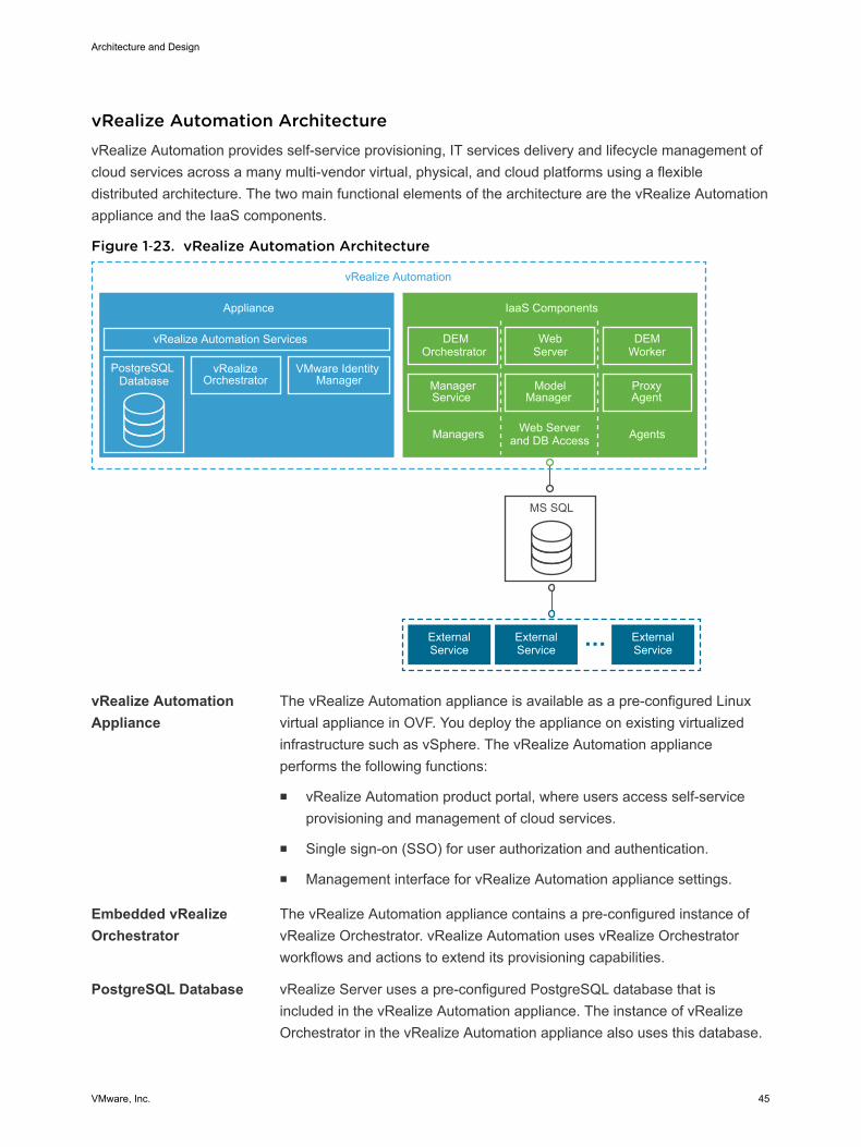
vRealize Automation ArchitecturevRealize Automation provides self-service provisioning, IT services delivery and lifecycle management ofcloud services across a many multi-vendor virtual, physical, and cloud platforms using a flexibledistributed architecture. The two main functional elements of the architecture are the vRealize Automationappliance and the IaaS components.
Figure 1‑23. vRealize Automation Architecture
ModelManager
ProxyAgent
vRealize Automation
Appliance
vRealize Automation Services
PostgreSQL Database
vRealizeOrchestrator
VMware Identity Manager
IaaS Components
MS SQL
ExternalService
ExternalService
ExternalService
DEMOrchestrator
WebServer
DEMWorker
ManagerService
Managers Web Serverand DB Access Agents
vRealize AutomationAppliance
The vRealize Automation appliance is available as a pre-configured Linuxvirtual appliance in OVF. You deploy the appliance on existing virtualizedinfrastructure such as vSphere. The vRealize Automation applianceperforms the following functions:
n vRealize Automation product portal, where users access self-serviceprovisioning and management of cloud services.
n Single sign-on (SSO) for user authorization and authentication.
n Management interface for vRealize Automation appliance settings.
Embedded vRealizeOrchestrator
The vRealize Automation appliance contains a pre-configured instance ofvRealize Orchestrator. vRealize Automation uses vRealize Orchestratorworkflows and actions to extend its provisioning capabilities.
PostgreSQL Database vRealize Server uses a pre-configured PostgreSQL database that isincluded in the vRealize Automation appliance. The instance of vRealizeOrchestrator in the vRealize Automation appliance also uses this database.
Architecture and Design
VMware, Inc. 45
Infrastructure as aService
vRealize Automation IaaS part consists of one or more Microsoft WindowsServer instances that work together to model and provision systems inprivate, public, or hybrid cloud infrastructures.
Model Manager vRealize Automation uses models to facilitate integration with externalsystems and databases. The models implement business logic used by theDistributed Execution Manager (DEM).
The Model Manager provides services and utilities for persisting,versioning, securing, and distributing model elements. The Model Manageris hosted on one of the IaaS Web servers and communicates with DEMs,the Microsoft SQL Server database, and the product interface Web site.
IaaS Web Server The IaaS Web server provides infrastructure administration and serviceauthoring to the vRealize Automation product interface. The web servercomponent communicates with the Manager Service, which providesupdates from the DEM, SQL Server database, and agents.
Manager Service The Manager Service is Windows service that coordinates thecommunication between IaaS DEMs, the SQL Server database, agents,and SMTP. The Manager Service communicates with the Web serverthrough the Model Manager, and must be run under a domain account withadministrator privileges on all IaaS Windows Server instances.
Distributed ExecutionManager Orchestrator
A Distributed Execution Manager (DEM) performs the business logic ofcustom models, interacting with the database and with external databasesand systems as required. A DEM orchestrator is responsible for monitoringDEM worker instances, pre-processing workflows for execution, andscheduling workflows.
Distributed ExecutionManager Worker
The IaaS DEM worker performs provisioning and de-provisioning tasksinitiated by the vRealize Automation portal. DEM workers alsocommunicate with specific infrastructure endpoints.
Proxy Agents vRealize Automation IaaS uses agents to integrate with external systemsand to manage information among vRealize Automation components. Forexample, a vSphere proxy agent sends commands to and collects datafrom an ESXi host about the virtual machines that you provisioned fromvRealize Automation.
VMware IdentityManager
VMware Identity Manager is the main identity provider for vRealizeAutomation. VMware Identity Manager manages user authentication, roles,permissions, and overall access to vRealize Automation using federatedidentity brokering. The following authentication methods are supported invRealize Automation using VMware Identity Manager:
n User name-password providing single-factor password authenticationwith basic Active Directory configuration or for local users
Architecture and Design
VMware, Inc. 46
n Kerberos
n Smart Card / Certificate
n RSA SecurID
n RADIUS
n RSA Adaptive Authentication
n SAML Authentication
Deployment ModelYou can deploy vRealize Automation in one of the following configurations:
n Small deployment for up to 10,000 managed virtual machines
n vRealize Automation appliance, potentially behind a load balancer
n IaaS node
n Microsoft SQL Server
n Medium deployment for up to 30,000 managed virtual machines
n 3 vRealize Automation appliances behind a load balancer
n 2 IaaS Web/Manager servers behind a load balancer
n 2 IaaS DEM servers
n 2 IaaS proxy agents
n Microsoft SQL Server
n Large deployment for up to 50,000 managed virtual machine
n 3 vRealize Automation appliances behind a load balancer
n 2 IaaS Web servers behind a load balancer
n 2 IaaS Manager servers behind a load balancer
n 2 IaaS DEM servers
n 2 IaaS proxy agents
n Microsoft SQL Server
To address future growth of tenant workloads beyond 10,000 virtual machines without more operationaloverhead, this design implements a large deployment of vRealize Automation.
Multi-Region vRealize Automation DeploymentThe scope of this validated design can cover both multiple regions and availability zones.
The scope of the VMware Validated Design includes vRealize Automation appliance large-scaledistributed deployment designed for a complete and highly available cloud management solution thatincludes:
Architecture and Design
VMware, Inc. 47
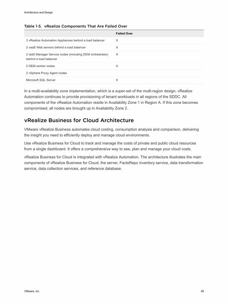
Table 1‑5. vRealize Components That Are Failed Over
Failed Over
3 vRealize Automation Appliances behind a load balancer X
2 vaaS Web servers behind a load balancer X
2 IaaS Manager Service nodes (including DEM orchestrator)behind a load balancer
X
2 DEM worker nodes X
2 vSphere Proxy Agent nodes
Microsoft SQL Server X
In a multi-availability zone implementation, which is a super-set of the multi-region design, vRealizeAutomation continues to provide provisioning of tenant workloads in all regions of the SDDC. Allcomponents of the vRealize Automation reside in Availability Zone 1 in Region A. If this zone becomescompromised, all nodes are brought up in Availability Zone 2.
vRealize Business for Cloud Architecture VMware vRealize Business automates cloud costing, consumption analysis and comparison, deliveringthe insight you need to efficiently deploy and manage cloud environments.
Use vRealize Business for Cloud to track and manage the costs of private and public cloud resourcesfrom a single dashboard. It offers a comprehensive way to see, plan and manage your cloud costs.
vRealize Business for Cloud is integrated with vRealize Automation. The architecture illustrates the maincomponents of vRealize Business for Cloud, the server, FactsRepo inventory service, data transformationservice, data collection services, and reference database.
Architecture and Design
VMware, Inc. 48
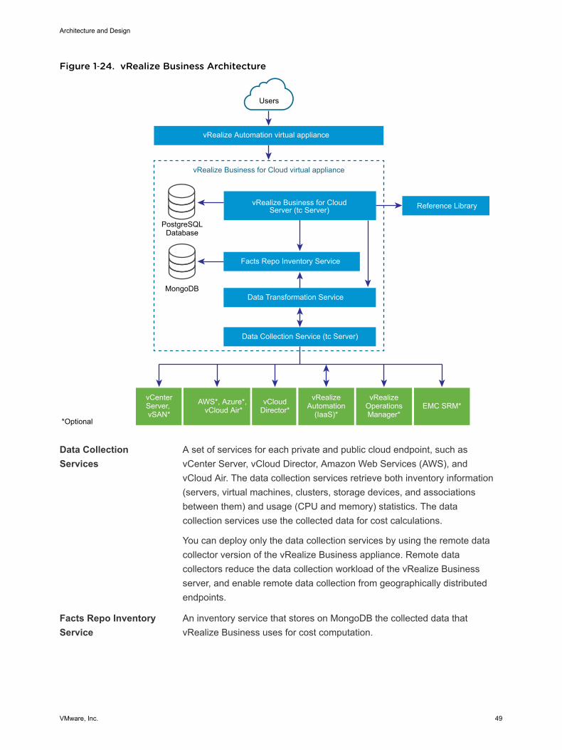
Figure 1‑24. vRealize Business Architecture
vRealize Business for Cloud virtual appliance
vRealize Automation virtual appliance
Users
vRealize Business for CloudServer (tc Server)
Facts Repo Inventory Service
PostgreSQLDatabase
Reference Library
MongoDBData Transformation Service
Data Collection Service (tc Server)
*Optional
vCenterServer, vSAN*
AWS*, Azure*, vCloud Air*
vCloudDirector*
vRealizeAutomation
(IaaS)*
vRealizeOperations Manager*
EMC SRM*
Data CollectionServices
A set of services for each private and public cloud endpoint, such asvCenter Server, vCloud Director, Amazon Web Services (AWS), andvCloud Air. The data collection services retrieve both inventory information(servers, virtual machines, clusters, storage devices, and associationsbetween them) and usage (CPU and memory) statistics. The datacollection services use the collected data for cost calculations.
You can deploy only the data collection services by using the remote datacollector version of the vRealize Business appliance. Remote datacollectors reduce the data collection workload of the vRealize Businessserver, and enable remote data collection from geographically distributedendpoints.
Facts Repo InventoryService
An inventory service that stores on MongoDB the collected data thatvRealize Business uses for cost computation.
Architecture and Design
VMware, Inc. 49
Data TransformationService
A service that converts source-specific data from the data collectionservices into data structures for consumption by the FactsRepo inventoryservice. The data transformation service serves as is a single point ofaggregation of data from all data collectors.
vRealize BusinessServer
A Web application that runs on Pivotal tc Server. vRealize Business hasmultiple data collection services that run periodically, collecting inventoryinformation and statistics, which are stored in a PostgreSQL database.Data that is collected from the data collection services is used for costcalculations.
Reference Database A database that is responsible for providing default, out-of-the-box costs foreach of the supported cost drivers. The reference database is updatedautomatically or manually, and you can download the latest data set andimport it into vRealize Business. The new values affect cost calculation.The reference data used depends on the currency you select at the time ofinstallation.
Important You cannot change the currency configuration after you deployvRealize Business for Cloud.
CommunicationBetween Server andReference Database
The reference database is a compressed and encrypted file, which you candownload and install manually or update automatically. You can update themost current version of reference database.
Other Sources ofInformation
These information sources are optional. You use them only if installed andconfigured. The sources include vRealize Automation, vCloud Director,vRealize Operations Manager, Amazon Web Services (AWS), MicrosoftAzure, vCloud Air, and EMC Storage Resource Manager (SRM).
Operational ModelvRealize Business for Cloud continuously collects data from external sources, and periodically updatesthe Facts Repo inventory service. You can view the collected data using the vRealize Businessdashboard or generate a report. Data synchronization and updates occur at regular intervals. You canalso manually trigger the data collection process when inventory changes occur. For example, inresponse to the initialization of the system, or addition of a cloud account.
BackupYou back up each vRealize Business node using traditional virtual machine backup solutions that arecompatible with VMware vSphere Storage APIs – Data Protection (VADP).
Multi-Region vRealize Business DeploymentThe scope of this validated design can cover both multiple regions and availability zones.
Architecture and Design
VMware, Inc. 50
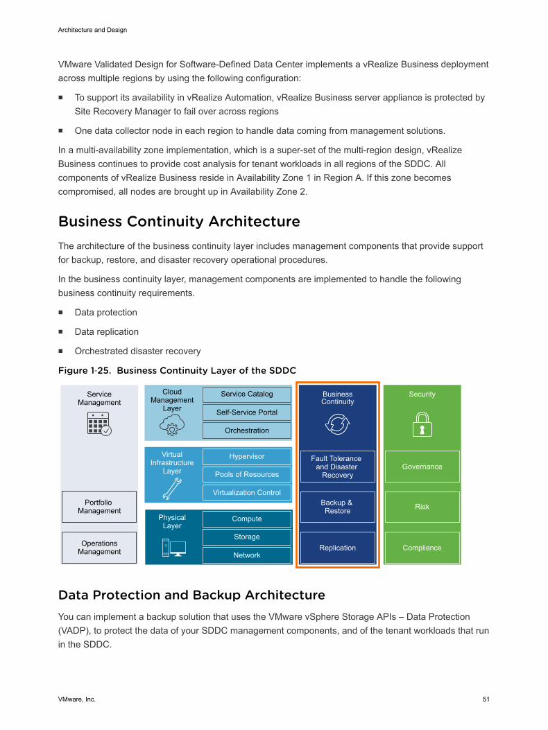
VMware Validated Design for Software-Defined Data Center implements a vRealize Business deploymentacross multiple regions by using the following configuration:
n To support its availability in vRealize Automation, vRealize Business server appliance is protected bySite Recovery Manager to fail over across regions
n One data collector node in each region to handle data coming from management solutions.
In a multi-availability zone implementation, which is a super-set of the multi-region design, vRealizeBusiness continues to provide cost analysis for tenant workloads in all regions of the SDDC. Allcomponents of vRealize Business reside in Availability Zone 1 in Region A. If this zone becomescompromised, all nodes are brought up in Availability Zone 2.
Business Continuity Architecture The architecture of the business continuity layer includes management components that provide supportfor backup, restore, and disaster recovery operational procedures.
In the business continuity layer, management components are implemented to handle the followingbusiness continuity requirements.
n Data protection
n Data replication
n Orchestrated disaster recovery
Figure 1‑25. Business Continuity Layer of the SDDC
ServiceManagement
Portfolio Management
OperationsManagement
CloudManagement
Layer
Service Catalog
Self-Service Portal
Orchestration
BusinessContinuity
Fault Tolerance and Disaster
Recovery
Backup & Restore
Hypervisor
Pools of Resources
Virtualization Control
VirtualInfrastructure
Layer
Compute
Storage
Network
PhysicalLayer
Security
Replication Compliance
Risk
Governance
Data Protection and Backup Architecture You can implement a backup solution that uses the VMware vSphere Storage APIs – Data Protection(VADP), to protect the data of your SDDC management components, and of the tenant workloads that runin the SDDC.
Architecture and Design
VMware, Inc. 51
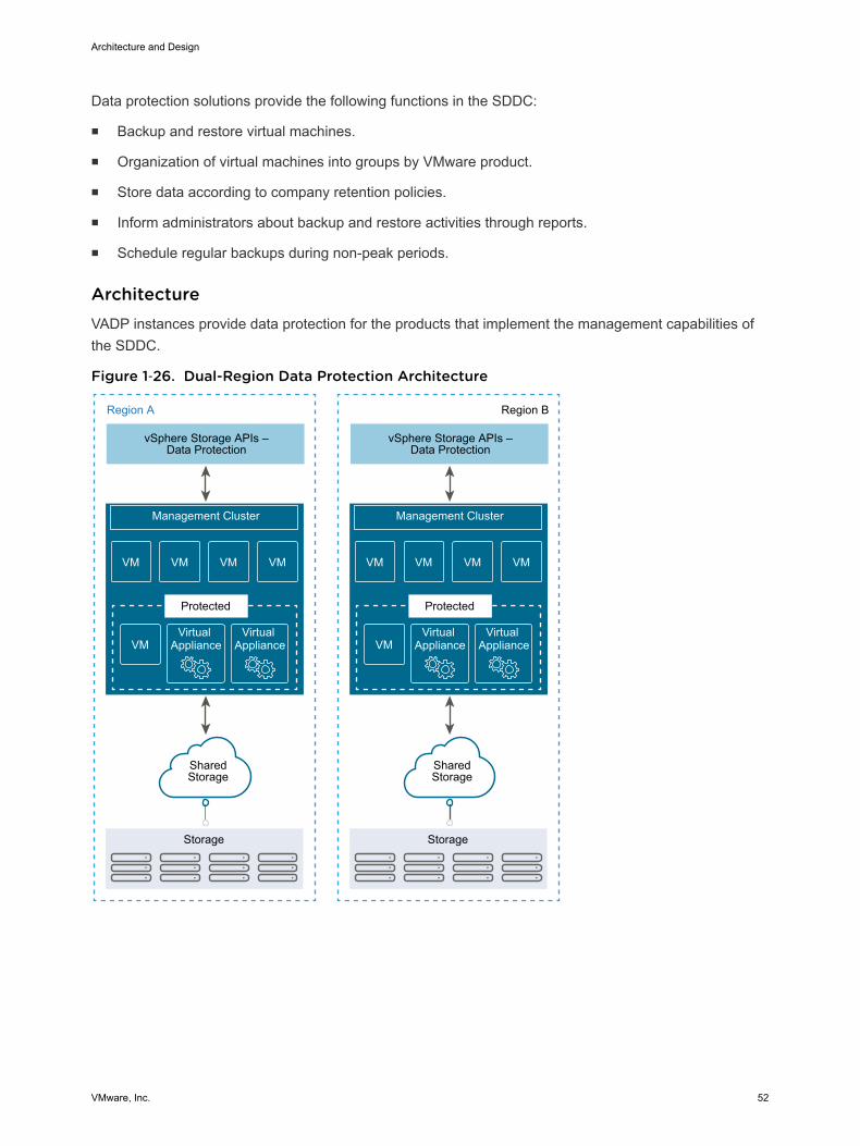
Data protection solutions provide the following functions in the SDDC:
n Backup and restore virtual machines.
n Organization of virtual machines into groups by VMware product.
n Store data according to company retention policies.
n Inform administrators about backup and restore activities through reports.
n Schedule regular backups during non-peak periods.
ArchitectureVADP instances provide data protection for the products that implement the management capabilities ofthe SDDC.
Figure 1‑26. Dual-Region Data Protection Architecture
VMVMVMVM
VMVirtual
ApplianceVirtual
Appliance
VMVMVMVM
VMVirtual
ApplianceVirtual
Appliance
vSphere Storage APIs –Data Protection
Management Cluster
Storage
Region A Region B
Protected
SharedStorage
vSphere Storage APIs –Data Protection
Management Cluster
Storage
Protected
SharedStorage
Architecture and Design
VMware, Inc. 52
Multi-Region Data Protection DeploymentBecause of its multi-region scope, the VMware Validated Design for Software-Defined Data Centersupports the deployment of a VADP-compatible backup solution in the management cluster for eachregion. To provide recovery of a number of SDDC management components, you configure backup jobs.The VADP-compatible backup solution stores the backups of the management virtual appliances on asecondary storage according to a defined schedule.
Disaster Recovery ArchitectureYou use Site Recovery Manager in conjunction with vSphere Replication and their constructs toimplement cross-region disaster recovery for the workloads of the management products in the SDDC. Toavoid outage reproduction in the protected region, use stretched storage clusters and implement anarchitecture with multiple availability zones.
ArchitectureDisaster recovery that is based on Site Recovery Manager has the following main elements:
Dual-regionconfiguration
All protected virtual machines are initially located in Region A which isconsidered as the protected region, and are recovered in Region B which isconsidered as the recovery region. In a typical Site RecoveryManager installation, the protected region provides business-critical datacenter services. The recovery region is an alternative infrastructure towhich Site Recovery Manager can relocate these services.
Replication of virtualmachine data
n Array-based replication. When you use array-based replication, one ormore storage arrays at the protected region replicate data to peerarrays at the recovery region. To use array-based replication with SiteRecovery Manager, you must configure replication first on the storagearray and install a storage specific adapter before you canconfigure Site Recovery Manager to use it.
n vSphere Replication. You configure vSphere Replication on virtualmachines independently of Site Recovery Manager. Replication doesnot occur at the storage array level. The replication source and targetstorage can be any storage device.
You can configure vSphere Replication to use the multiple-point-in-timesnapshot feature enabling more flexibility for data recovery of protectedvirtual machines on the recovery region.
Architecture and Design
VMware, Inc. 53
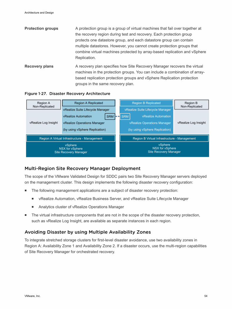
Protection groups A protection group is a group of virtual machines that fail over together atthe recovery region during test and recovery. Each protection groupprotects one datastore group, and each datastore group can containmultiple datastores. However, you cannot create protection groups thatcombine virtual machines protected by array-based replication and vSphereReplication.
Recovery plans A recovery plan specifies how Site Recovery Manager recovers the virtualmachines in the protection groups. You can include a combination of array-based replication protection groups and vSphere Replication protectiongroups in the same recovery plan.
Figure 1‑27. Disaster Recovery Architecture
Region A Non-Replicated
vRealize Log Insight
Region A Virtual Infrastructure - Management
vSphere NSX for vSphere
Site Recovery Manager
Region B Non-Replicated
vRealize Log Insight
Region B Replicated
vRealize Suite Lifecycle Manager
vRealize Automation
vRealize Operations Manager
(by using vSphere Replication)
SRM
Region A Replicated
SRM
vRealize Suite Lifecycle Manager
vRealize Automation
vRealize Operations Manager
(by using vSphere Replication)
Region B Virtual Infrastructure - Management
vSphereNSX for vSphere
Site Recovery Manager
Multi-Region Site Recovery Manager DeploymentThe scope of the VMware Validated Design for SDDC pairs two Site Recovery Manager servers deployedon the management cluster. This design implements the following disaster recovery configuration:
n The following management applications are a subject of disaster recovery protection:
n vRealize Automation, vRealize Business Server, and vRealize Suite Lifecycle Manager
n Analytics cluster of vRealize Operations Manager
n The virtual infrastructure components that are not in the scope of the disaster recovery protection,such as vRealize Log Insight, are available as separate instances in each region.
Avoiding Disaster by using Multiple Availability ZonesTo integrate stretched storage clusters for first-level disaster avoidance, use two availability zones inRegion A: Availability Zone 1 and Availability Zone 2. If a disaster occurs, use the multi-region capabilitiesof Site Recovery Manager for orchestrated recovery.
Architecture and Design
VMware, Inc. 54
Detailed Design 2The Software-Defined Data Center (SDDC) detailed design considers both physical and virtualinfrastructure design. It includes numbered design decisions, and the justification and implications of eachdecision.
This design provides two design options for availability zone setup. In certain areas, configurations anddesign decision alternatives are specific to a single availability zone setup and to a multiple availabilityzone setup.
Physical InfrastructureDesign
Focuses on the three main aspects of any data center: compute, storage,and network. In this section, you find information about availability zonesand regions. The section also provides details on the rack and clusterconfiguration, and on physical ESXi hosts and the associated storage andnetwork configurations.
Virtual InfrastructureDesign
Provides details on the core virtualization software configuration. Thissection has information on the ESXi hypervisor, vCenter Server, the virtualnetwork design including VMware NSX, and on software-defined storagefor VMware vSAN. This section also includes details on business continuity(backup and restore) and on disaster recovery.
OperationsInfrastructure Design
Explains how to architect, install, and configure vRealize Suite LifecycleManager, vSphere Update Manager, vRealize Operations Manager,vRealize Log Insight for lifecycle and service management.
Cloud ManagementPlatform Design
Contains information on the consumption and orchestration layer of theSDDC stack, which uses vRealize Automation, vRealize Orchestrator, andvRealize Business. IT organizations can use the fully distributed andscalable architecture to streamline their provisioning and decommissioningoperations.
This chapter includes the following topics:
n Physical Infrastructure Design
n Virtual Infrastructure Design
n Operations Management Design
VMware, Inc. 55
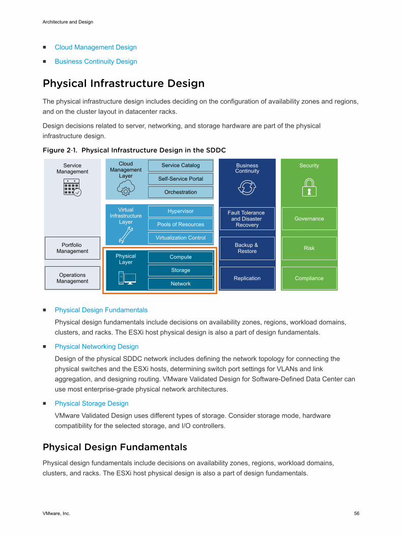
n Cloud Management Design
n Business Continuity Design
Physical Infrastructure Design The physical infrastructure design includes deciding on the configuration of availability zones and regions,and on the cluster layout in datacenter racks.
Design decisions related to server, networking, and storage hardware are part of the physicalinfrastructure design.
Figure 2‑1. Physical Infrastructure Design in the SDDC
ServiceManagement
Portfolio Management
OperationsManagement
CloudManagement
Layer
Service Catalog
Self-Service Portal
Orchestration
BusinessContinuity
Fault Tolerance and Disaster
Recovery
Backup & Restore
Hypervisor
Pools of Resources
Virtualization Control
VirtualInfrastructure
Layer
Compute
Storage
Network
PhysicalLayer
Security
Replication Compliance
Risk
Governance
n Physical Design Fundamentals
Physical design fundamentals include decisions on availability zones, regions, workload domains,clusters, and racks. The ESXi host physical design is also a part of design fundamentals.
n Physical Networking Design
Design of the physical SDDC network includes defining the network topology for connecting thephysical switches and the ESXi hosts, determining switch port settings for VLANs and linkaggregation, and designing routing. VMware Validated Design for Software-Defined Data Center canuse most enterprise-grade physical network architectures.
n Physical Storage Design
VMware Validated Design uses different types of storage. Consider storage mode, hardwarecompatibility for the selected storage, and I/O controllers.
Physical Design Fundamentals Physical design fundamentals include decisions on availability zones, regions, workload domains,clusters, and racks. The ESXi host physical design is also a part of design fundamentals.
Architecture and Design
VMware, Inc. 56

Availability Zones and Regions Availability zones and regions have different purposes. Availability zones protect against failures ofindividual hosts. Regions provide disaster recovery of the entire SDDC. This design deploys a protectedregion with one or two availability zones and recovery region with a single availability zone.
Availability zones An availability zone is the fault domain of the SDDC. Multiple availabilityzones can provide continuous availability of an SDDC, minimize down timeof services and improve SLAs.
Regions Regions provide disaster recovery across different SDDC instances. Eachregion is a separate SDDC instance. The regions have a similar physicallayer and virtual infrastructure designs but different naming.
The SDDC in this validated design contains two regions.
The identifiers follow United Nations Code for Trade and Transport Locations(UN/LOCODE) and alsocontain a numeric instance ID.
Table 2‑1. Availability Zones and Regions in SDDC
RegionAvailability Zone andRegion Identifier Region-Specific Domain Name Region Description
A SFO01 sfo01.rainpole.local Availability Zone 1 in San Francisco, CA, USAbased data center
A SFO02 sfo01.rainpole.local Availability Zone 2 in San Francisco, CA, USAbased data center
B LAX01 lax01.rainpole.local Los Angeles, CA, USA based data center
Table 2‑2. Design Decisions оn Availability Zones and Regions
Decision ID Design Decision Design Justification Design Implication
SDDC-PHY-001
In Region A, deploy one ortwo availability zones tosupport all SDDCmanagement componentsand their SLAs.
Supports all SDDC managementand compute components for aregion.
n Using a single availability zone resultsin limited redundancy of the overallsolution.
n The single availability zone canbecome a single point of failure andprevent high-availability designsolutions in a region.
Supports stretched clusters andapplication-aware failover forhigh availability between twophysical locations.
Implementing two availability zonesincreases the solution footprint and cancomplicate the operational procedures.
Architecture and Design
VMware, Inc. 57
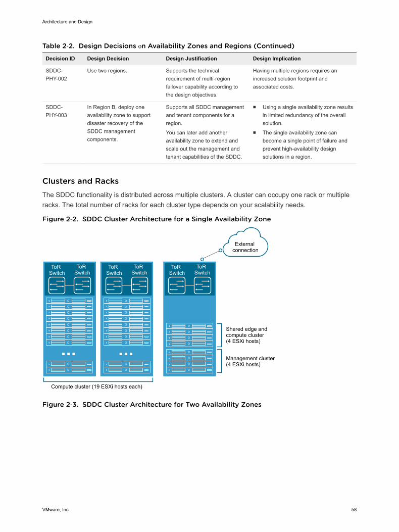
Table 2‑2. Design Decisions оn Availability Zones and Regions (Continued)
Decision ID Design Decision Design Justification Design Implication
SDDC-PHY-002
Use two regions. Supports the technicalrequirement of multi-regionfailover capability according tothe design objectives.
Having multiple regions requires anincreased solution footprint andassociated costs.
SDDC-PHY-003
In Region B, deploy oneavailability zone to supportdisaster recovery of theSDDC managementcomponents.
Supports all SDDC managementand tenant components for aregion.
You can later add anotheravailability zone to extend andscale out the management andtenant capabilities of the SDDC.
n Using a single availability zone resultsin limited redundancy of the overallsolution.
n The single availability zone canbecome a single point of failure andprevent high-availability designsolutions in a region.
Clusters and Racks The SDDC functionality is distributed across multiple clusters. A cluster can occupy one rack or multipleracks. The total number of racks for each cluster type depends on your scalability needs.
Figure 2‑2. SDDC Cluster Architecture for a Single Availability Zone
ToR Switch
ToR Switch
ToR Switch
ToR Switch
Compute cluster (19 ESXi hosts each)
Shared edge andcompute cluster(4 ESXi hosts)
Management cluster(4 ESXi hosts)
External connection
ToR Switch
ToR Switch
Figure 2‑3. SDDC Cluster Architecture for Two Availability Zones
Architecture and Design
VMware, Inc. 58
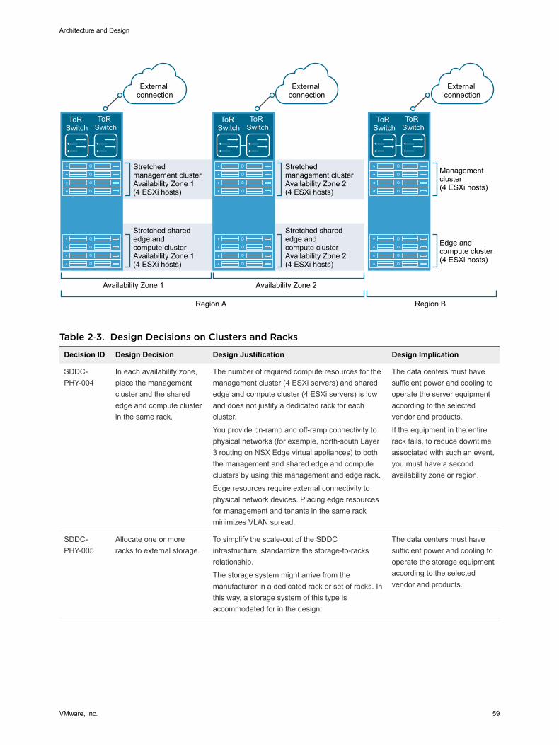
Availability Zone 1
Management cluster(4 ESXi hosts)
Еdge andcompute cluster(4 ESXi hosts)
ToR Switch
ToR Switch
Stretchedmanagement clusterAvailability Zone 1(4 ESXi hosts)
Stretched sharededge andcompute clusterAvailability Zone 1(4 ESXi hosts)
External connection
External connection
External connection
ToR Switch
ToR Switch
Stretchedmanagement clusterAvailability Zone 2(4 ESXi hosts)
Stretched sharededge and compute clusterAvailability Zone 2(4 ESXi hosts)
ToR Switch
ToR Switch
Availability Zone 2
Region A Region B
Table 2‑3. Design Decisions on Clusters and Racks
Decision ID Design Decision Design Justification Design Implication
SDDC-PHY-004
In each availability zone,place the managementcluster and the sharededge and compute clusterin the same rack.
The number of required compute resources for themanagement cluster (4 ESXi servers) and sharededge and compute cluster (4 ESXi servers) is lowand does not justify a dedicated rack for eachcluster.
You provide on-ramp and off-ramp connectivity tophysical networks (for example, north-south Layer3 routing on NSX Edge virtual appliances) to boththe management and shared edge and computeclusters by using this management and edge rack.
Edge resources require external connectivity tophysical network devices. Placing edge resourcesfor management and tenants in the same rackminimizes VLAN spread.
The data centers must havesufficient power and cooling tooperate the server equipmentaccording to the selectedvendor and products.
If the equipment in the entirerack fails, to reduce downtimeassociated with such an event,you must have a secondavailability zone or region.
SDDC-PHY-005
Allocate one or moreracks to external storage.
To simplify the scale-out of the SDDCinfrastructure, standardize the storage-to-racksrelationship.
The storage system might arrive from themanufacturer in a dedicated rack or set of racks. Inthis way, a storage system of this type isaccommodated for in the design.
The data centers must havesufficient power and cooling tooperate the storage equipmentaccording to the selectedvendor and products.
Architecture and Design
VMware, Inc. 59
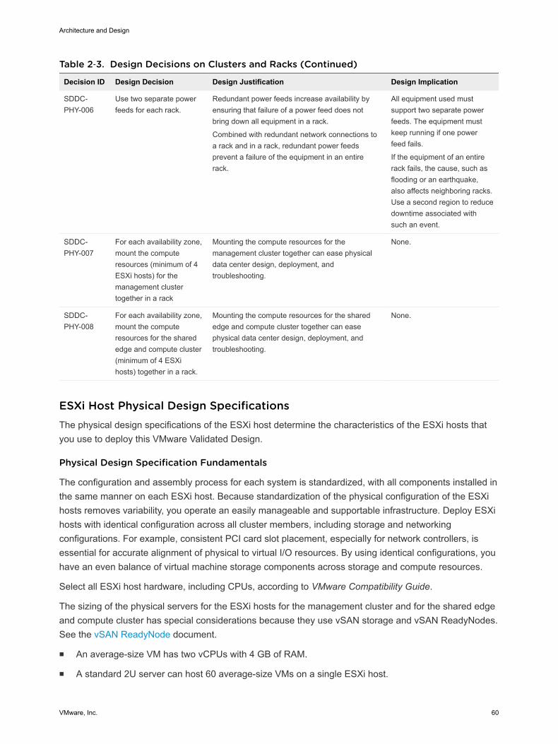
Table 2‑3. Design Decisions on Clusters and Racks (Continued)
Decision ID Design Decision Design Justification Design Implication
SDDC-PHY-006
Use two separate powerfeeds for each rack.
Redundant power feeds increase availability byensuring that failure of a power feed does notbring down all equipment in a rack.
Combined with redundant network connections toa rack and in a rack, redundant power feedsprevent a failure of the equipment in an entirerack.
All equipment used mustsupport two separate powerfeeds. The equipment mustkeep running if one powerfeed fails.
If the equipment of an entirerack fails, the cause, such asflooding or an earthquake,also affects neighboring racks.Use a second region to reducedowntime associated withsuch an event.
SDDC-PHY-007
For each availability zone,mount the computeresources (minimum of 4ESXi hosts) for themanagement clustertogether in a rack
Mounting the compute resources for themanagement cluster together can ease physicaldata center design, deployment, andtroubleshooting.
None.
SDDC-PHY-008
For each availability zone,mount the computeresources for the sharededge and compute cluster(minimum of 4 ESXihosts) together in a rack.
Mounting the compute resources for the sharededge and compute cluster together can easephysical data center design, deployment, andtroubleshooting.
None.
ESXi Host Physical Design Specifications The physical design specifications of the ESXi host determine the characteristics of the ESXi hosts thatyou use to deploy this VMware Validated Design.
Physical Design Specification Fundamentals
The configuration and assembly process for each system is standardized, with all components installed inthe same manner on each ESXi host. Because standardization of the physical configuration of the ESXihosts removes variability, you operate an easily manageable and supportable infrastructure. Deploy ESXihosts with identical configuration across all cluster members, including storage and networkingconfigurations. For example, consistent PCI card slot placement, especially for network controllers, isessential for accurate alignment of physical to virtual I/O resources. By using identical configurations, youhave an even balance of virtual machine storage components across storage and compute resources.
Select all ESXi host hardware, including CPUs, according to VMware Compatibility Guide.
The sizing of the physical servers for the ESXi hosts for the management cluster and for the shared edgeand compute cluster has special considerations because they use vSAN storage and vSAN ReadyNodes.See the vSAN ReadyNode document.
n An average-size VM has two vCPUs with 4 GB of RAM.
n A standard 2U server can host 60 average-size VMs on a single ESXi host.
Architecture and Design
VMware, Inc. 60
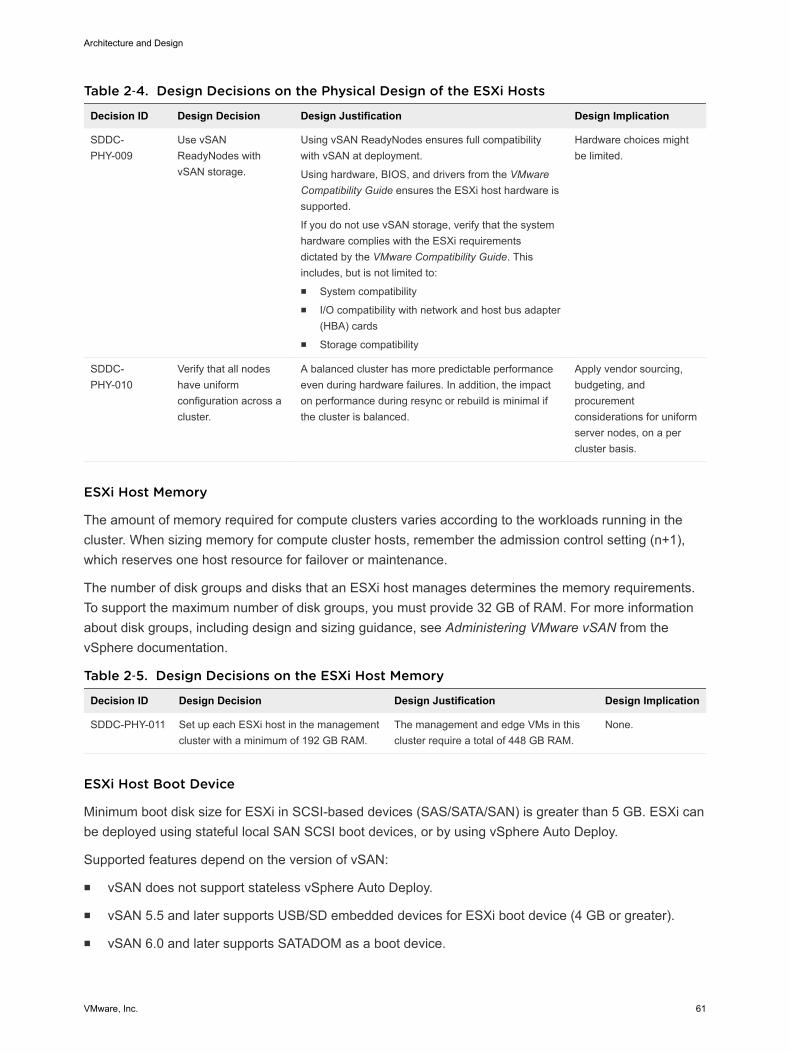
Table 2‑4. Design Decisions on the Physical Design of the ESXi Hosts
Decision ID Design Decision Design Justification Design Implication
SDDC-PHY-009
Use vSANReadyNodes withvSAN storage.
Using vSAN ReadyNodes ensures full compatibilitywith vSAN at deployment.
Using hardware, BIOS, and drivers from the VMwareCompatibility Guide ensures the ESXi host hardware issupported.
If you do not use vSAN storage, verify that the systemhardware complies with the ESXi requirementsdictated by the VMware Compatibility Guide. Thisincludes, but is not limited to:n System compatibilityn I/O compatibility with network and host bus adapter
(HBA) cardsn Storage compatibility
Hardware choices mightbe limited.
SDDC-PHY-010
Verify that all nodeshave uniformconfiguration across acluster.
A balanced cluster has more predictable performanceeven during hardware failures. In addition, the impacton performance during resync or rebuild is minimal ifthe cluster is balanced.
Apply vendor sourcing,budgeting, andprocurementconsiderations for uniformserver nodes, on a percluster basis.
ESXi Host Memory
The amount of memory required for compute clusters varies according to the workloads running in thecluster. When sizing memory for compute cluster hosts, remember the admission control setting (n+1),which reserves one host resource for failover or maintenance.
The number of disk groups and disks that an ESXi host manages determines the memory requirements.To support the maximum number of disk groups, you must provide 32 GB of RAM. For more informationabout disk groups, including design and sizing guidance, see Administering VMware vSAN from thevSphere documentation.
Table 2‑5. Design Decisions on the ESXi Host Memory
Decision ID Design Decision Design Justification Design Implication
SDDC-PHY-011 Set up each ESXi host in the managementcluster with a minimum of 192 GB RAM.
The management and edge VMs in thiscluster require a total of 448 GB RAM.
None.
ESXi Host Boot Device
Minimum boot disk size for ESXi in SCSI-based devices (SAS/SATA/SAN) is greater than 5 GB. ESXi canbe deployed using stateful local SAN SCSI boot devices, or by using vSphere Auto Deploy.
Supported features depend on the version of vSAN:
n vSAN does not support stateless vSphere Auto Deploy.
n vSAN 5.5 and later supports USB/SD embedded devices for ESXi boot device (4 GB or greater).
n vSAN 6.0 and later supports SATADOM as a boot device.
Architecture and Design
VMware, Inc. 61
See VMware vSAN Design and Sizing Guide to select the option that best fits your hardware.
Physical Networking Design Design of the physical SDDC network includes defining the network topology for connecting the physicalswitches and the ESXi hosts, determining switch port settings for VLANs and link aggregation, anddesigning routing. VMware Validated Design for Software-Defined Data Center can use most enterprise-grade physical network architectures.
Switch Types and Network Connectivity Follow best practices for physical switches, switch connectivity, setup of VLANs and subnets, and accessport settings.
Top of Rack Physical Switches
When configuring top of rack (ToR) switches, consider the following best practices.
n Configure redundant physical switches to enhance availability.
n Configure switch ports that connect to ESXi hosts manually as trunk ports. Virtual switches arepassive devices and do not support trunking protocols, such as Dynamic Trunking Protocol (DTP).
n Modify the Spanning Tree Protocol (STP) on any port that is connected to an ESXi NIC to reduce thetime it takes to transition ports over to the forwarding state, for example, using the Trunk PortFastfeature on a Cisco physical switch.
n Provide DHCP or DHCP Helper capabilities on all VLANs that are used by the management andVXLAN VMkernel ports. This setup simplifies the configuration by using DHCP to assign IP addressbased on the IP subnet in use.
n Configure jumbo frames on all switch ports, inter-switch link (ISL) and switched virtual interfaces(SVIs).
Top of Rack Connectivity and Network Settings
Each ESXi host is connected redundantly to the SDDC network fabric ToR switches by using two 10 GbEports. Configure the ToR switches to provide all necessary VLANs via an 802.1Q trunk. These redundantconnections use features of vSphere Distributed Switch and NSX for vSphere to guarantee no physicalinterface is overrun and redundant paths are used as long as they are available.
This Validated Design does not use hardware-based link aggregation. However, it is a valid design optionand is supported by VMware. If you use hardware-based link aggregation, check vendor firmwareversions and VMware product documentation to verify support requirements. See VMware CloudFoundation documentation for a VMware validated and supported design using hardware-based linkaggregation.
Architecture and Design
VMware, Inc. 62
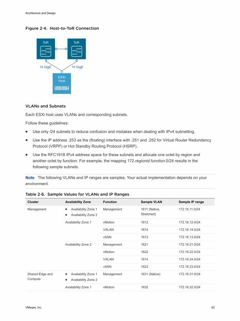
Figure 2‑4. Host-to-ToR Connection
ToR ToR
ESXiHost
10 GigE 10 GigE
VLANs and Subnets
Each ESXi host uses VLANs and corresponding subnets.
Follow these guidelines:
n Use only /24 subnets to reduce confusion and mistakes when dealing with IPv4 subnetting.
n Use the IP address .253 as the (floating) interface with .251 and .252 for Virtual Router RedundancyProtocol (VRPP) or Hot Standby Routing Protocol (HSRP).
n Use the RFC1918 IPv4 address space for these subnets and allocate one octet by region andanother octet by function. For example, the mapping 172.regionid.function.0/24 results in thefollowing sample subnets.
Note The following VLANs and IP ranges are samples. Your actual implementation depends on yourenvironment.
Table 2‑6. Sample Values for VLANs and IP Ranges
Cluster Availability Zone Function Sample VLAN Sample IP range
Management n Availability Zone 1n Availability Zone 2
Management 1611 (Native,Stretched)
172.16.11.0/24
Availability Zone 1 vMotion 1612 172.16.12.0/24
VXLAN 1614 172.16.14.0/24
vSAN 1613 172.16.13.0/24
Availability Zone 2 Management 1621 172.16.21.0/24
vMotion 1622 172.16.22.0/24
VXLAN 1614 172.16.24.0/24
vSAN 1623 172.16.23.0/24
Shared Edge andCompute
n Availability Zone 1n Availability Zone 2
Management 1631 (Native) 172.16.31.0/24
Availability Zone 1 vMotion 1632 172.16.32.0/24
Architecture and Design
VMware, Inc. 63
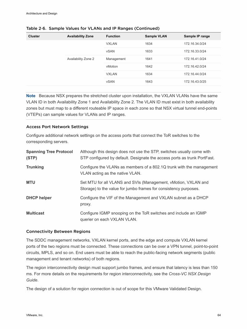
Table 2‑6. Sample Values for VLANs and IP Ranges (Continued)
Cluster Availability Zone Function Sample VLAN Sample IP range
VXLAN 1634 172.16.34.0/24
vSAN 1633 172.16.33.0/24
Availability Zone 2 Management 1641 172.16.41.0/24
vMotion 1642 172.16.42.0/24
VXLAN 1634 172.16.44.0/24
vSAN 1643 172.16.43.0/25
Note Because NSX prepares the stretched cluster upon installation, the VXLAN VLANs have the sameVLAN ID in both Availability Zone 1 and Availability Zone 2. The VLAN ID must exist in both availabilityzones but must map to a different routeable IP space in each zone so that NSX virtual tunnel end-points(VTEPs) can sample values for VLANs and IP ranges.
Access Port Network Settings
Configure additional network settings on the access ports that connect the ToR switches to thecorresponding servers.
Spanning Tree Protocol(STP)
Although this design does not use the STP, switches usually come withSTP configured by default. Designate the access ports as trunk PortFast.
Trunking Configure the VLANs as members of a 802.1Q trunk with the managementVLAN acting as the native VLAN.
MTU Set MTU for all VLANS and SVIs (Management, vMotion, VXLAN andStorage) to the value for jumbo frames for consistency purposes.
DHCP helper Configure the VIF of the Management and VXLAN subnet as a DHCPproxy.
Multicast Configure IGMP snooping on the ToR switches and include an IGMPquerier on each VXLAN VLAN.
Connectivity Between Regions
The SDDC management networks, VXLAN kernel ports, and the edge and compute VXLAN kernelports of the two regions must be connected. These connections can be over a VPN tunnel, point-to-pointcircuits, MPLS, and so on. End users must be able to reach the public-facing network segments (publicmanagement and tenant networks) of both regions.
The region interconnectivity design must support jumbo frames, and ensure that latency is less than 150ms. For more details on the requirements for region interconnectivity, see the Cross-VC NSX DesignGuide.
The design of a solution for region connection is out of scope for this VMware Validated Design.
Architecture and Design
VMware, Inc. 64
Physical Network Design Decisions The physical network design decisions determine the physical layout and use of VLANs. They alsoinclude decisions on jumbo frames and on other network-related requirements such as DNS and NTP.
Physical Network Design Decisions
Routing protocols Base the selection of the external routing protocol on your currentimplementation or on available expertise among the IT staff. Considerperformance requirements. Possible options are OSPF, BGP, and IS-IS.Although each routing protocol has a complex set of advantages anddisadvantages, this validated design utilizes BGP as its routing protocol.
DHCP proxy Set the DHCP proxy to point to a DHCP server by IPv4 address. See theVMware Validated Design Planning and Preparation document for detailson the DHCP server.
Table 2‑7. Design Decisions on the Physical Network
Decision ID Design Decision Design Justification Design Implication
SDDC-PHY-NET-001
Implement the following physicalnetwork architecture:n One 10-GbE port on each
ToR switch for ESXi hostuplinks
n No EtherChannel (LAG/vPC)configuration for ESXi hostuplinks
n Layer 3 device with BGP andIGMP support
n Guarantees availability during a switchfailure.
n Provides compatibility with vSphere hostprofiles because they do not store link-aggregation settings.
n Supports BGP as the dynamic routingprotocol in the SDDC.
n Provides compatibility with NSX hybridmode replication because it requiresIGMP.
Hardware choices mightbe limited.
Requires dynamic routingprotocol configuration inthe physical networkingstack.
SDDC-PHY-NET-002
Use a physical network that isconfigured for BGP routingadjacency.
This design uses BGP as its routingprotocol. Supports flexibility in networkdesign for routing multi-site and multi-tenancy workloads.
Requires BGPconfiguration in thephysical networking stack.
SDDC-PHY-NET-003
Use two ToR switches for eachrack.
This design uses two 10-GbE links to eachserver and provides redundancy andreduces the overall design complexity.
Requires two ToRswitches per rack whichcan increase costs.
SDDC-PHY-NET-004
Use VLANs to segment physicalnetwork functions.
n Supports physical network connectivitywithout requiring many NICs.
n Isolates the different network functionsof the SDDC so that you can havedifferentiated services and prioritizedtraffic as needed.
Requires uniformconfiguration andpresentation on all thetrunks made available tothe ESXi hosts.
Additional Design Decisions
Additional design decisions deal with static IP addresses, DNS records, and the required NTP timesource.
Architecture and Design
VMware, Inc. 65
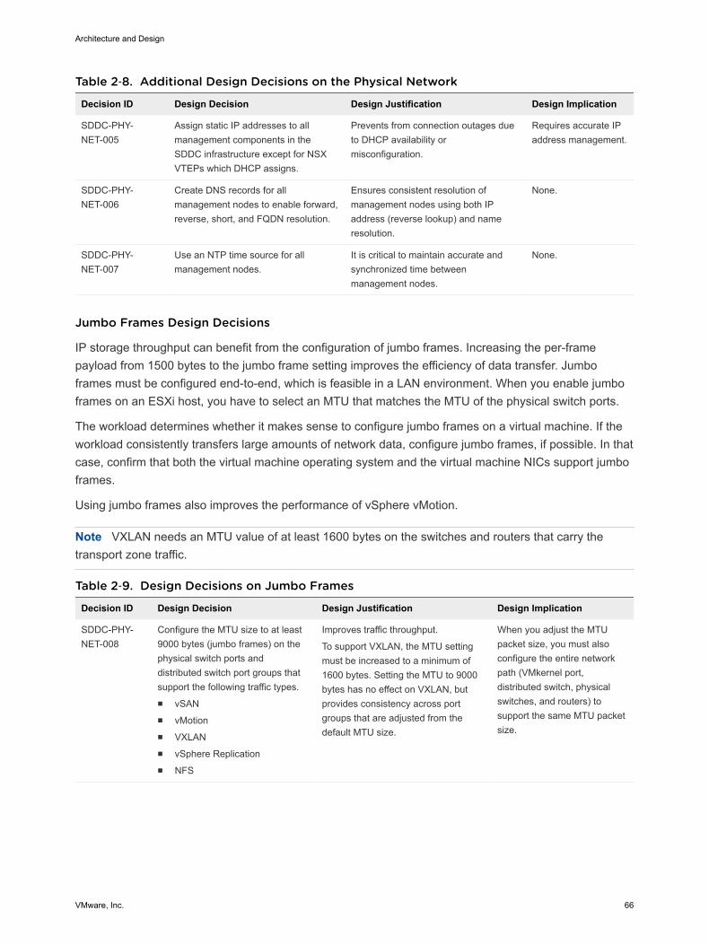
Table 2‑8. Additional Design Decisions on the Physical Network
Decision ID Design Decision Design Justification Design Implication
SDDC-PHY-NET-005
Assign static IP addresses to allmanagement components in theSDDC infrastructure except for NSXVTEPs which DHCP assigns.
Prevents from connection outages dueto DHCP availability ormisconfiguration.
Requires accurate IPaddress management.
SDDC-PHY-NET-006
Create DNS records for allmanagement nodes to enable forward,reverse, short, and FQDN resolution.
Ensures consistent resolution ofmanagement nodes using both IPaddress (reverse lookup) and nameresolution.
None.
SDDC-PHY-NET-007
Use an NTP time source for allmanagement nodes.
It is critical to maintain accurate andsynchronized time betweenmanagement nodes.
None.
Jumbo Frames Design Decisions
IP storage throughput can benefit from the configuration of jumbo frames. Increasing the per-framepayload from 1500 bytes to the jumbo frame setting improves the efficiency of data transfer. Jumboframes must be configured end-to-end, which is feasible in a LAN environment. When you enable jumboframes on an ESXi host, you have to select an MTU that matches the MTU of the physical switch ports.
The workload determines whether it makes sense to configure jumbo frames on a virtual machine. If theworkload consistently transfers large amounts of network data, configure jumbo frames, if possible. In thatcase, confirm that both the virtual machine operating system and the virtual machine NICs support jumboframes.
Using jumbo frames also improves the performance of vSphere vMotion.
Note VXLAN needs an MTU value of at least 1600 bytes on the switches and routers that carry thetransport zone traffic.
Table 2‑9. Design Decisions on Jumbo Frames
Decision ID Design Decision Design Justification Design Implication
SDDC-PHY-NET-008
Configure the MTU size to at least9000 bytes (jumbo frames) on thephysical switch ports anddistributed switch port groups thatsupport the following traffic types.n vSANn vMotionn VXLANn vSphere Replicationn NFS
Improves traffic throughput.
To support VXLAN, the MTU settingmust be increased to a minimum of1600 bytes. Setting the MTU to 9000bytes has no effect on VXLAN, butprovides consistency across portgroups that are adjusted from thedefault MTU size.
When you adjust the MTUpacket size, you must alsoconfigure the entire networkpath (VMkernel port,distributed switch, physicalswitches, and routers) tosupport the same MTU packetsize.
Architecture and Design
VMware, Inc. 66
Physical Storage Design VMware Validated Design uses different types of storage. Consider storage mode, hardware compatibilityfor the selected storage, and I/O controllers.
All functional testing and validation of the design is on vSAN. Although VMware Validated Design usesvSAN, in particular for the clusters running management components, you can use any supported storagesolution.
If you select a storage solution other than vSAN, you must take into account that all the design,deployment, and Day-2 guidance in VMware Validated Design applies under the context of vSAN andadjust appropriately.
Your storage design must match or exceed the capacity and performance capabilities of the vSANconfiguration in the design. For multiple availability zones, the vSAN configuration includes vSANstretched cluster.
vSAN Physical Design This design uses VMware vSAN to implement software-defined storage for the management clusters. Byusing vSAN, you have a high level of control on the storage subsystem.
vSAN is a hyper-converged storage software that is fully integrated with the hypervisor. vSAN creates acluster of server hard disk drives and solid state drives, and presents a flash-optimized, highly-resilient,shared storage datastore to ESXi hosts and virtual machines. By using vSAN storage policies, you cancontrol capacity, performance, and availability on a per virtual machine basis.
Requirements and Dependencies
The software-defined storage module has the following requirements and options.
Architecture and Design
VMware, Inc. 67
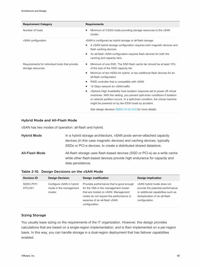
Requirement Category Requirements
Number of hosts n Minimum of 3 ESXi hosts providing storage resources to the vSANcluster.
vSAN configuration vSAN is configured as hybrid storage or all-flash storage. n A vSAN hybrid storage configuration requires both magnetic devices and
flash caching devices.n An all-flash vSAN configuration requires flash devices for both the
caching and capacity tiers.
Requirements for individual hosts that providestorage resources
n Minimum of one SSD. The SSD flash cache tier should be at least 10%of the size of the HDD capacity tier.
n Minimum of two HDDs for hybrid, or two additional flash devices for anall-flash configuration
n RAID controller that is compatible with vSAN. n 10 Gbps network for vSAN traffic.n vSphere High Availability host isolation response set to power off virtual
machines. With this setting, you prevent split-brain conditions if isolationor network partition occurs. In a split-brain condition, the virtual machinemight be powered on by two ESXi hosts by accident.
See design decision SDDC-VI-VC-012 for more details.
Hybrid Mode and All-Flash Mode
vSAN has two modes of operation: all-flash and hybrid.
Hybrid Mode In a hybrid storage architecture, vSAN pools server-attached capacitydevices (in this case magnetic devices) and caching devices, typicallySSDs or PCI-e devices, to create a distributed shared datastore.
All-Flash Mode All-flash storage uses flash-based devices (SSD or PCI-e) as a write cachewhile other flash-based devices provide high endurance for capacity anddata persistence.
Table 2‑10. Design Decisions on the vSAN Mode
Decision ID Design Decision Design Justification Design Implication
SDDC-PHY-STO-001
Configure vSAN in hybridmode in the managementcluster.
Provides performance that is good enoughfor the VMs in the management clusterthat are hosted on vSAN. Managementnodes do not require the performance orexpense of an all-flash vSANconfiguration.
vSAN hybrid mode does notprovide the potential performanceor additional capabilities such asdeduplication of an all-flashconfiguration.
Sizing Storage
You usually base sizing on the requirements of the IT organization. However, this design providescalculations that are based on a single-region implementation, and is then implemented on a per-regionbasis. In this way, you can handle storage in a dual-region deployment that has failover capabilitiesenabled.
Architecture and Design
VMware, Inc. 68
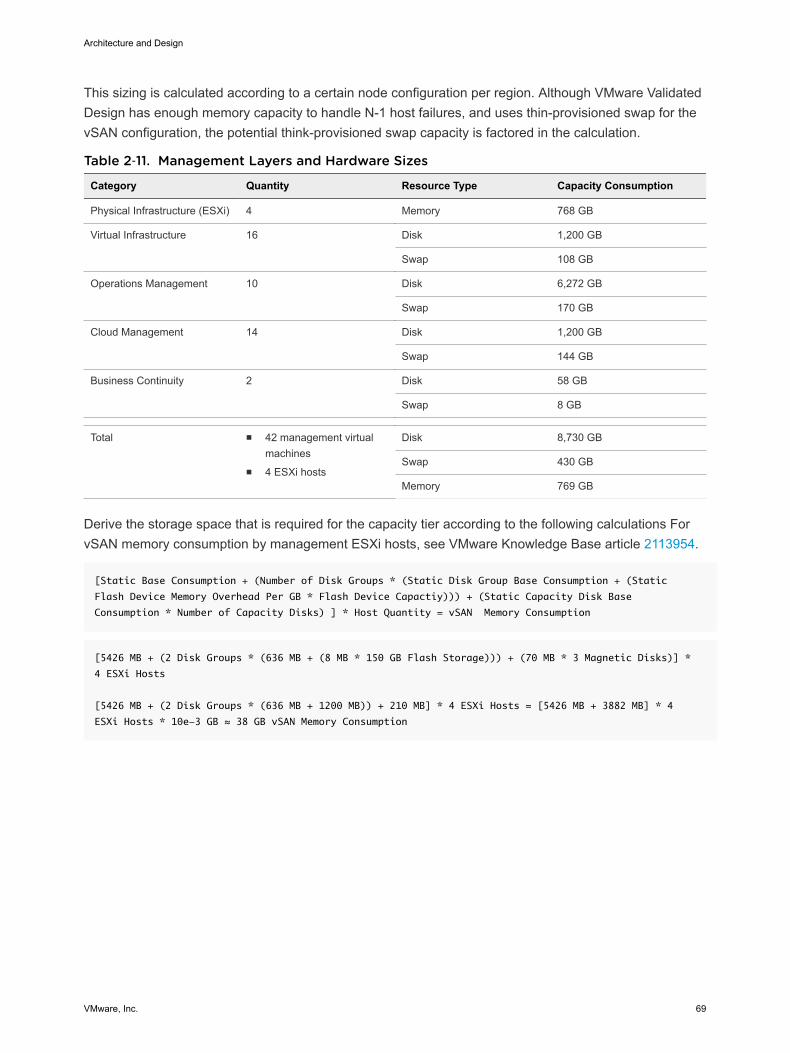
This sizing is calculated according to a certain node configuration per region. Although VMware ValidatedDesign has enough memory capacity to handle N-1 host failures, and uses thin-provisioned swap for thevSAN configuration, the potential think-provisioned swap capacity is factored in the calculation.
Table 2‑11. Management Layers and Hardware Sizes
Category Quantity Resource Type Capacity Consumption
Physical Infrastructure (ESXi) 4 Memory 768 GB
Virtual Infrastructure 16 Disk 1,200 GB
Swap 108 GB
Operations Management 10 Disk 6,272 GB
Swap 170 GB
Cloud Management 14 Disk 1,200 GB
Swap 144 GB
Business Continuity 2 Disk 58 GB
Swap 8 GB
Total n 42 management virtualmachines
n 4 ESXi hosts
Disk 8,730 GB
Swap 430 GB
Memory 769 GB
Derive the storage space that is required for the capacity tier according to the following calculations ForvSAN memory consumption by management ESXi hosts, see VMware Knowledge Base article 2113954.
[Static Base Consumption + (Number of Disk Groups * (Static Disk Group Base Consumption + (Static
Flash Device Memory Overhead Per GB * Flash Device Capactiy))) + (Static Capacity Disk Base
Consumption * Number of Capacity Disks) ] * Host Quantity = vSAN Memory Consumption
[5426 MB + (2 Disk Groups * (636 MB + (8 MB * 150 GB Flash Storage))) + (70 MB * 3 Magnetic Disks)] *
4 ESXi Hosts
[5426 MB + (2 Disk Groups * (636 MB + 1200 MB)) + 210 MB] * 4 ESXi Hosts = [5426 MB + 3882 MB] * 4
ESXi Hosts * 10e-3 GB ≈ 38 GB vSAN Memory Consumption
Architecture and Design
VMware, Inc. 69
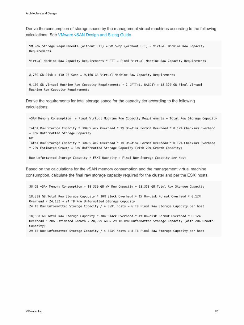
Derive the consumption of storage space by the management virtual machines according to the followingcalculations. See VMware vSAN Design and Sizing Guide.
VM Raw Storage Requirements (without FTT) + VM Swap (without FTT) = Virtual Machine Raw Capacity
Requirements
Virtual Machine Raw Capacity Requirements * FTT = Final Virtual Machine Raw Capacity Requirements
8,730 GB Disk + 430 GB Swap = 9,160 GB Virtual Machine Raw Capacity Requirements
9,160 GB Virtual Machine Raw Capacity Requirements * 2 (FTT=1, RAID1) = 18,320 GB Final Virtual
Machine Raw Capacity Requirements
Derive the requirements for total storage space for the capacity tier according to the followingcalculations:
vSAN Memory Consumption + Final Virtual Machine Raw Capacity Requirements = Total Raw Storage Capacity
Total Raw Storage Capacity * 30% Slack Overhead * 1% On-disk Format Overhead * 0.12% Checksum Overhead
= Raw Unformatted Storage Capacity
OR
Total Raw Storage Capacity * 30% Slack Overhead * 1% On-disk Format Overhead * 0.12% Checksum Overhead
* 20% Estimated Growth = Raw Unformatted Storage Capacity (with 20% Growth Capacity)
Raw Unformatted Storage Capacity / ESXi Quantity = Final Raw Storage Capacity per Host
Based on the calculations for the vSAN memory consumption and the management virtual machineconsumption, calculate the final raw storage capacity required for the cluster and per the ESXi hosts.
38 GB vSAN Memory Consumption + 18,320 GB VM Raw Capactiy = 18,358 GB Total Raw Storage Capacity
18,358 GB Total Raw Storage Capacity * 30% Slack Overhead * 1% On-disk Format Overhead * 0.12%
Overhead ≈ 24,132 ≈ 24 TB Raw Unformatted Storage Capacity
24 TB Raw Unformatted Storage Capacity / 4 ESXi hosts ≈ 6 TB Final Raw Storage Capacity per host
18,358 GB Total Raw Storage Capacity * 30% Slack Overhead * 1% On-disk Format Overhead * 0.12%
Overhead * 20% Estimated Growth ≈ 28,959 GB ≈ 29 TB Raw Unformatted Storage Capacity (with 20% Growth
Capacity)
29 TB Raw Unformatted Storage Capacity / 4 ESXi hosts ≈ 8 TB Final Raw Storage Capacity per host
Architecture and Design
VMware, Inc. 70
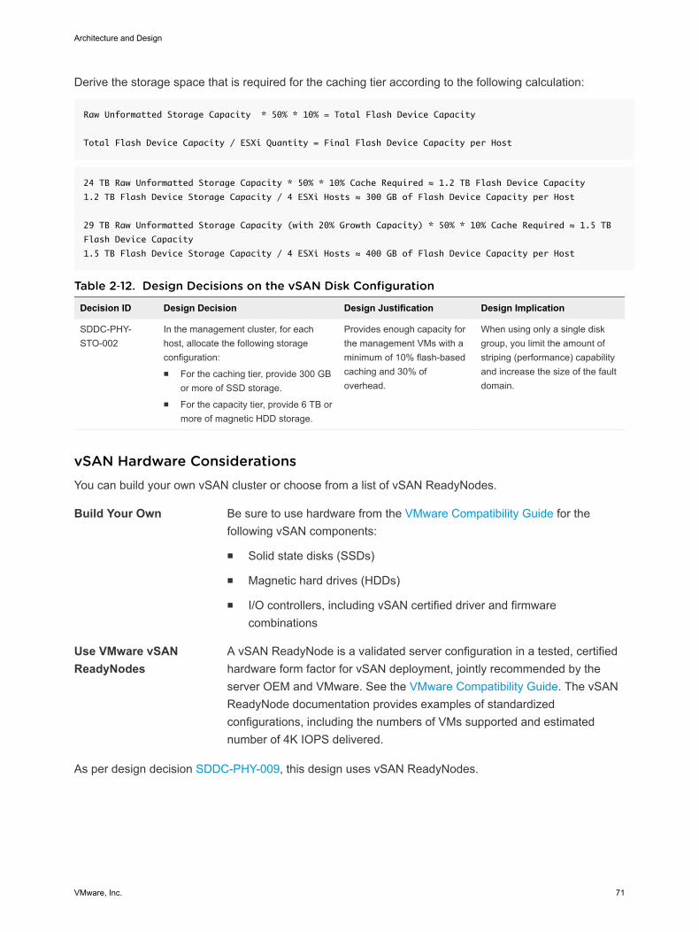
Derive the storage space that is required for the caching tier according to the following calculation:
Raw Unformatted Storage Capacity * 50% * 10% = Total Flash Device Capacity
Total Flash Device Capacity / ESXi Quantity = Final Flash Device Capacity per Host
24 TB Raw Unformatted Storage Capacity * 50% * 10% Cache Required ≈ 1.2 TB Flash Device Capacity
1.2 TB Flash Device Storage Capacity / 4 ESXi Hosts ≈ 300 GB of Flash Device Capacity per Host
29 TB Raw Unformatted Storage Capacity (with 20% Growth Capacity) * 50% * 10% Cache Required ≈ 1.5 TB
Flash Device Capacity
1.5 TB Flash Device Storage Capacity / 4 ESXi Hosts ≈ 400 GB of Flash Device Capacity per Host
Table 2‑12. Design Decisions on the vSAN Disk Configuration
Decision ID Design Decision Design Justification Design Implication
SDDC-PHY-STO-002
In the management cluster, for eachhost, allocate the following storageconfiguration:n For the caching tier, provide 300 GB
or more of SSD storage.n For the capacity tier, provide 6 TB or
more of magnetic HDD storage.
Provides enough capacity forthe management VMs with aminimum of 10% flash-basedcaching and 30% ofoverhead.
When using only a single diskgroup, you limit the amount ofstriping (performance) capabilityand increase the size of the faultdomain.
vSAN Hardware Considerations You can build your own vSAN cluster or choose from a list of vSAN ReadyNodes.
Build Your Own Be sure to use hardware from the VMware Compatibility Guide for thefollowing vSAN components:
n Solid state disks (SSDs)
n Magnetic hard drives (HDDs)
n I/O controllers, including vSAN certified driver and firmwarecombinations
Use VMware vSANReadyNodes
A vSAN ReadyNode is a validated server configuration in a tested, certifiedhardware form factor for vSAN deployment, jointly recommended by theserver OEM and VMware. See the VMware Compatibility Guide. The vSANReadyNode documentation provides examples of standardizedconfigurations, including the numbers of VMs supported and estimatednumber of 4K IOPS delivered.
As per design decision SDDC-PHY-009, this design uses vSAN ReadyNodes.
Architecture and Design
VMware, Inc. 71
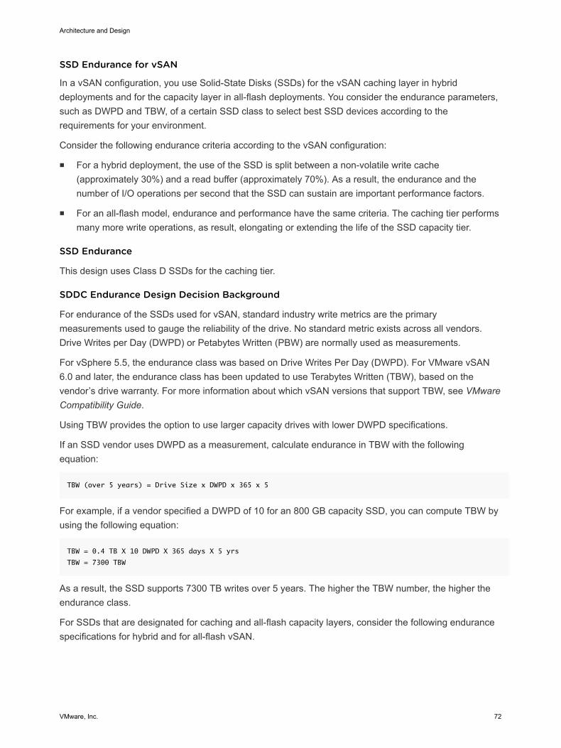
SSD Endurance for vSAN
In a vSAN configuration, you use Solid-State Disks (SSDs) for the vSAN caching layer in hybriddeployments and for the capacity layer in all-flash deployments. You consider the endurance parameters,such as DWPD and TBW, of a certain SSD class to select best SSD devices according to therequirements for your environment.
Consider the following endurance criteria according to the vSAN configuration:
n For a hybrid deployment, the use of the SSD is split between a non-volatile write cache(approximately 30%) and a read buffer (approximately 70%). As a result, the endurance and thenumber of I/O operations per second that the SSD can sustain are important performance factors.
n For an all-flash model, endurance and performance have the same criteria. The caching tier performsmany more write operations, as result, elongating or extending the life of the SSD capacity tier.
SSD Endurance
This design uses Class D SSDs for the caching tier.
SDDC Endurance Design Decision Background
For endurance of the SSDs used for vSAN, standard industry write metrics are the primarymeasurements used to gauge the reliability of the drive. No standard metric exists across all vendors.Drive Writes per Day (DWPD) or Petabytes Written (PBW) are normally used as measurements.
For vSphere 5.5, the endurance class was based on Drive Writes Per Day (DWPD). For VMware vSAN6.0 and later, the endurance class has been updated to use Terabytes Written (TBW), based on thevendor’s drive warranty. For more information about which vSAN versions that support TBW, see VMwareCompatibility Guide.
Using TBW provides the option to use larger capacity drives with lower DWPD specifications.
If an SSD vendor uses DWPD as a measurement, calculate endurance in TBW with the followingequation:
TBW (over 5 years) = Drive Size x DWPD x 365 x 5
For example, if a vendor specified a DWPD of 10 for an 800 GB capacity SSD, you can compute TBW byusing the following equation:
TBW = 0.4 TB X 10 DWPD X 365 days X 5 yrs
TBW = 7300 TBW
As a result, the SSD supports 7300 TB writes over 5 years. The higher the TBW number, the higher theendurance class.
For SSDs that are designated for caching and all-flash capacity layers, consider the following endurancespecifications for hybrid and for all-flash vSAN.
Architecture and Design
VMware, Inc. 72
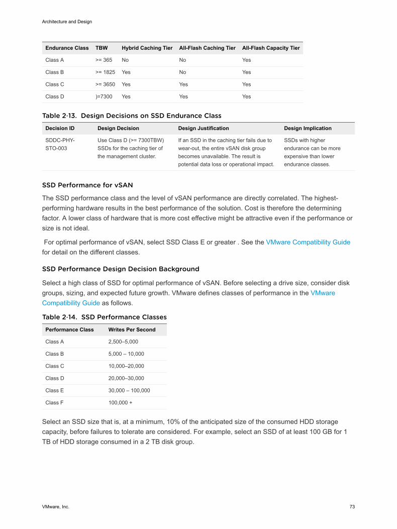
Endurance Class TBW Hybrid Caching Tier All-Flash Caching Tier All-Flash Capacity Tier
Class A >= 365 No No Yes
Class B >= 1825 Yes No Yes
Class C >= 3650 Yes Yes Yes
Class D )=7300 Yes Yes Yes
Table 2‑13. Design Decisions on SSD Endurance Class
Decision ID Design Decision Design Justification Design Implication
SDDC-PHY-STO-003
Use Class D (>= 7300TBW)SSDs for the caching tier ofthe management cluster.
If an SSD in the caching tier fails due towear-out, the entire vSAN disk groupbecomes unavailable. The result ispotential data loss or operational impact.
SSDs with higherendurance can be moreexpensive than lowerendurance classes.
SSD Performance for vSAN
The SSD performance class and the level of vSAN performance are directly correlated. The highest-performing hardware results in the best performance of the solution. Cost is therefore the determiningfactor. A lower class of hardware that is more cost effective might be attractive even if the performance orsize is not ideal.
For optimal performance of vSAN, select SSD Class E or greater . See the VMware Compatibility Guidefor detail on the different classes.
SSD Performance Design Decision Background
Select a high class of SSD for optimal performance of vSAN. Before selecting a drive size, consider diskgroups, sizing, and expected future growth. VMware defines classes of performance in the VMwareCompatibility Guide as follows.
Table 2‑14. SSD Performance Classes
Performance Class Writes Per Second
Class A 2,500–5,000
Class B 5,000 – 10,000
Class C 10,000–20,000
Class D 20,000–30,000
Class E 30,000 – 100,000
Class F 100,000 +
Select an SSD size that is, at a minimum, 10% of the anticipated size of the consumed HDD storagecapacity, before failures to tolerate are considered. For example, select an SSD of at least 100 GB for 1TB of HDD storage consumed in a 2 TB disk group.
Architecture and Design
VMware, Inc. 73
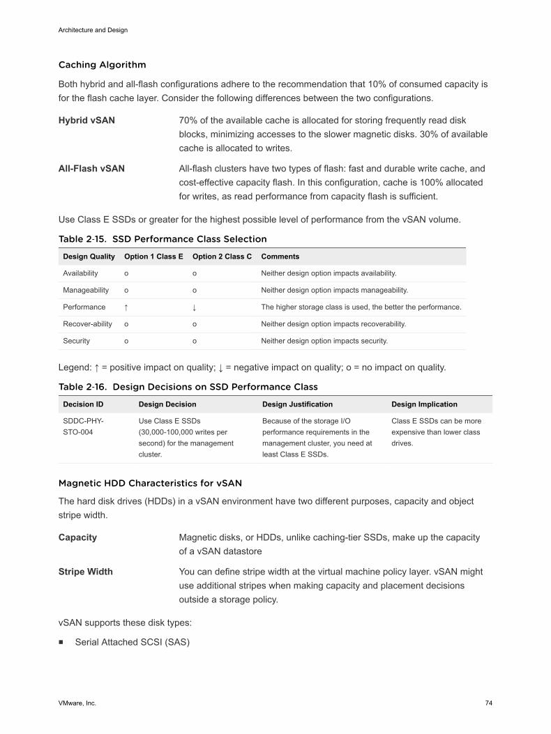
Caching Algorithm
Both hybrid and all-flash configurations adhere to the recommendation that 10% of consumed capacity isfor the flash cache layer. Consider the following differences between the two configurations.
Hybrid vSAN 70% of the available cache is allocated for storing frequently read diskblocks, minimizing accesses to the slower magnetic disks. 30% of availablecache is allocated to writes.
All-Flash vSAN All-flash clusters have two types of flash: fast and durable write cache, andcost-effective capacity flash. In this configuration, cache is 100% allocatedfor writes, as read performance from capacity flash is sufficient.
Use Class E SSDs or greater for the highest possible level of performance from the vSAN volume.
Table 2‑15. SSD Performance Class Selection
Design Quality Option 1 Class E Option 2 Class C Comments
Availability o o Neither design option impacts availability.
Manageability o o Neither design option impacts manageability.
Performance ↑ ↓ The higher storage class is used, the better the performance.
Recover-ability o o Neither design option impacts recoverability.
Security o o Neither design option impacts security.
Legend: ↑ = positive impact on quality; ↓ = negative impact on quality; o = no impact on quality.
Table 2‑16. Design Decisions on SSD Performance Class
Decision ID Design Decision Design Justification Design Implication
SDDC-PHY-STO-004
Use Class E SSDs(30,000-100,000 writes persecond) for the managementcluster.
Because of the storage I/Operformance requirements in themanagement cluster, you need atleast Class E SSDs.
Class E SSDs can be moreexpensive than lower classdrives.
Magnetic HDD Characteristics for vSAN
The hard disk drives (HDDs) in a vSAN environment have two different purposes, capacity and objectstripe width.
Capacity Magnetic disks, or HDDs, unlike caching-tier SSDs, make up the capacityof a vSAN datastore
Stripe Width You can define stripe width at the virtual machine policy layer. vSAN mightuse additional stripes when making capacity and placement decisionsoutside a storage policy.
vSAN supports these disk types:
n Serial Attached SCSI (SAS)
Architecture and Design
VMware, Inc. 74
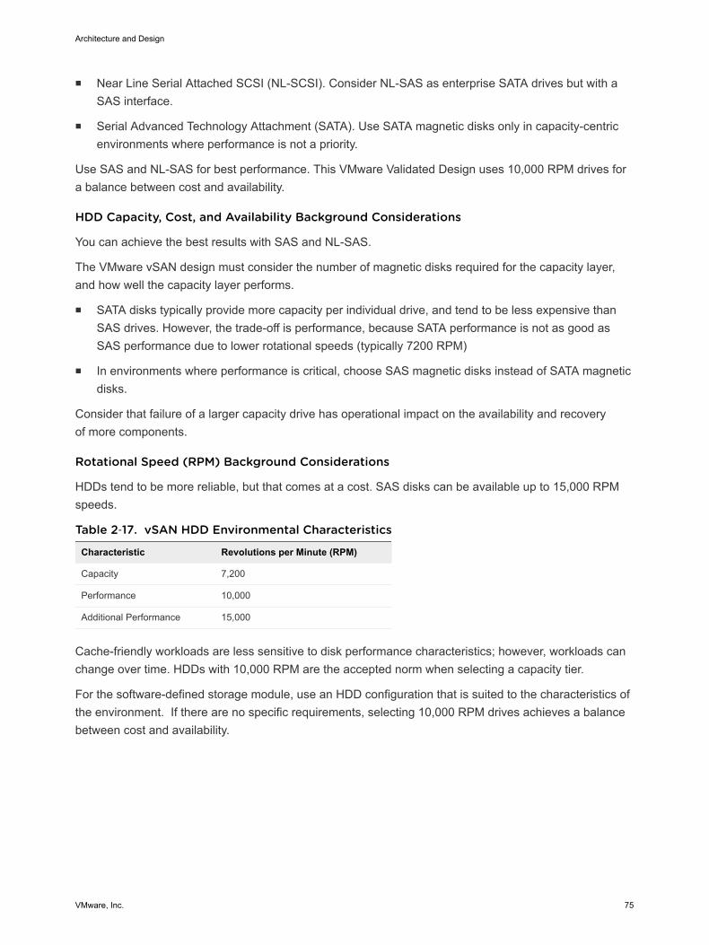
n Near Line Serial Attached SCSI (NL-SCSI). Consider NL-SAS as enterprise SATA drives but with aSAS interface.
n Serial Advanced Technology Attachment (SATA). Use SATA magnetic disks only in capacity-centricenvironments where performance is not a priority.
Use SAS and NL-SAS for best performance. This VMware Validated Design uses 10,000 RPM drives fora balance between cost and availability.
HDD Capacity, Cost, and Availability Background Considerations
You can achieve the best results with SAS and NL-SAS.
The VMware vSAN design must consider the number of magnetic disks required for the capacity layer,and how well the capacity layer performs.
n SATA disks typically provide more capacity per individual drive, and tend to be less expensive thanSAS drives. However, the trade-off is performance, because SATA performance is not as good asSAS performance due to lower rotational speeds (typically 7200 RPM)
n In environments where performance is critical, choose SAS magnetic disks instead of SATA magneticdisks.
Consider that failure of a larger capacity drive has operational impact on the availability and recoveryof more components.
Rotational Speed (RPM) Background Considerations
HDDs tend to be more reliable, but that comes at a cost. SAS disks can be available up to 15,000 RPMspeeds.
Table 2‑17. vSAN HDD Environmental Characteristics
Characteristic Revolutions per Minute (RPM)
Capacity 7,200
Performance 10,000
Additional Performance 15,000
Cache-friendly workloads are less sensitive to disk performance characteristics; however, workloads canchange over time. HDDs with 10,000 RPM are the accepted norm when selecting a capacity tier.
For the software-defined storage module, use an HDD configuration that is suited to the characteristics ofthe environment. If there are no specific requirements, selecting 10,000 RPM drives achieves a balancebetween cost and availability.
Architecture and Design
VMware, Inc. 75
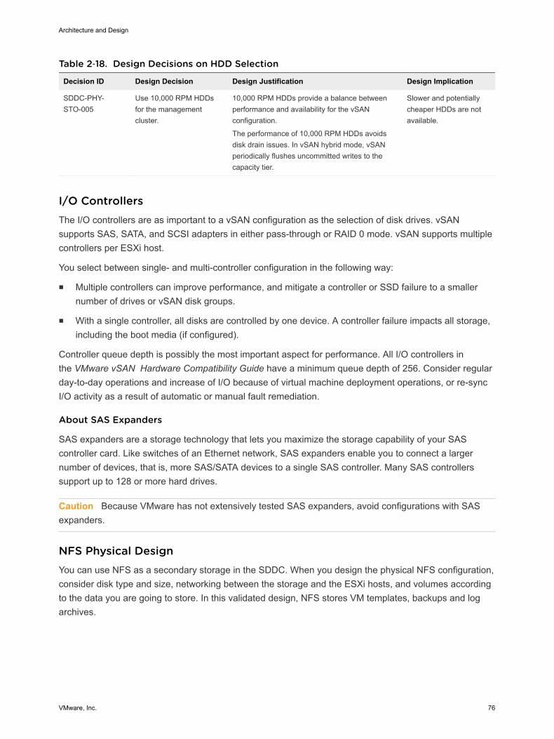
Table 2‑18. Design Decisions on HDD Selection
Decision ID Design Decision Design Justification Design Implication
SDDC-PHY-STO-005
Use 10,000 RPM HDDsfor the managementcluster.
10,000 RPM HDDs provide a balance betweenperformance and availability for the vSANconfiguration.
The performance of 10,000 RPM HDDs avoidsdisk drain issues. In vSAN hybrid mode, vSANperiodically flushes uncommitted writes to thecapacity tier.
Slower and potentiallycheaper HDDs are notavailable.
I/O Controllers The I/O controllers are as important to a vSAN configuration as the selection of disk drives. vSANsupports SAS, SATA, and SCSI adapters in either pass-through or RAID 0 mode. vSAN supports multiplecontrollers per ESXi host.
You select between single- and multi-controller configuration in the following way:
n Multiple controllers can improve performance, and mitigate a controller or SSD failure to a smallernumber of drives or vSAN disk groups.
n With a single controller, all disks are controlled by one device. A controller failure impacts all storage,including the boot media (if configured).
Controller queue depth is possibly the most important aspect for performance. All I/O controllers inthe VMware vSAN Hardware Compatibility Guide have a minimum queue depth of 256. Consider regularday-to-day operations and increase of I/O because of virtual machine deployment operations, or re-syncI/O activity as a result of automatic or manual fault remediation.
About SAS Expanders
SAS expanders are a storage technology that lets you maximize the storage capability of your SAScontroller card. Like switches of an Ethernet network, SAS expanders enable you to connect a largernumber of devices, that is, more SAS/SATA devices to a single SAS controller. Many SAS controllerssupport up to 128 or more hard drives.
Caution Because VMware has not extensively tested SAS expanders, avoid configurations with SASexpanders.
NFS Physical Design You can use NFS as a secondary storage in the SDDC. When you design the physical NFS configuration,consider disk type and size, networking between the storage and the ESXi hosts, and volumes accordingto the data you are going to store. In this validated design, NFS stores VM templates, backups and logarchives.
Architecture and Design
VMware, Inc. 76
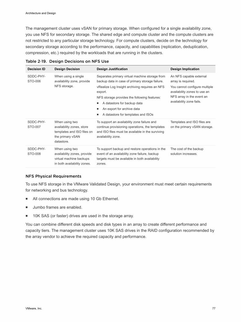
The management cluster uses vSAN for primary storage. When configured for a single availability zone,you use NFS for secondary storage. The shared edge and compute cluster and the compute clusters arenot restricted to any particular storage technology. For compute clusters, decide on the technology forsecondary storage according to the performance, capacity, and capabilities (replication, deduplication,compression, etc.) required by the workloads that are running in the clusters.
Table 2‑19. Design Decisions on NFS Use
Decision ID Design Decision Design Justification Design Implication
SDDC-PHY-STO-006
When using a singleavailability zone, provideNFS storage.
Separates primary virtual machine storage frombackup data in case of primary storage failure.
vRealize Log Insight archiving requires an NFSexport.
NFS storage provides the following features:n A datastore for backup datan An export for archive datan A datastore for templates and ISOs
An NFS capable externalarray is required.
You cannot configure multipleavailability zones to use anNFS array in the event anavailability zone fails.
SDDC-PHY-STO-007
When using twoavailability zones, storetemplates and ISO files onthe primary vSANdatastore.
To support an availability zone failure andcontinue provisioning operations, the templatesand ISO files must be available in the survivingavailability zone.
Templates and ISO files areon the primary vSAN storage.
SDDC-PHY-STO-008
When using twoavailability zones, providevirtual machine backupsin both availability zones.
To support backup and restore operations in theevent of an availability zone failure, backuptargets must be available in both availabilityzones.
The cost of the backupsolution increases.
NFS Physical Requirements
To use NFS storage in the VMware Validated Design, your environment must meet certain requirementsfor networking and bus technology.
n All connections are made using 10 Gb Ethernet.
n Jumbo frames are enabled.
n 10K SAS (or faster) drives are used in the storage array.
You can combine different disk speeds and disk types in an array to create different performance andcapacity tiers. The management cluster uses 10K SAS drives in the RAID configuration recommended bythe array vendor to achieve the required capacity and performance.
Architecture and Design
VMware, Inc. 77
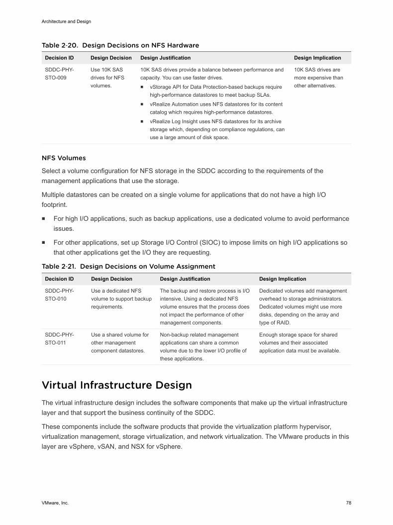
Table 2‑20. Design Decisions on NFS Hardware
Decision ID Design Decision Design Justification Design Implication
SDDC-PHY-STO-009
Use 10K SASdrives for NFSvolumes.
10K SAS drives provide a balance between performance andcapacity. You can use faster drives.n vStorage API for Data Protection-based backups require
high-performance datastores to meet backup SLAs.n vRealize Automation uses NFS datastores for its content
catalog which requires high-performance datastores.n vRealize Log Insight uses NFS datastores for its archive
storage which, depending on compliance regulations, canuse a large amount of disk space.
10K SAS drives aremore expensive thanother alternatives.
NFS Volumes
Select a volume configuration for NFS storage in the SDDC according to the requirements of themanagement applications that use the storage.
Multiple datastores can be created on a single volume for applications that do not have a high I/Ofootprint.
n For high I/O applications, such as backup applications, use a dedicated volume to avoid performanceissues.
n For other applications, set up Storage I/O Control (SIOC) to impose limits on high I/O applications sothat other applications get the I/O they are requesting.
Table 2‑21. Design Decisions on Volume Assignment
Decision ID Design Decision Design Justification Design Implication
SDDC-PHY-STO-010
Use a dedicated NFSvolume to support backuprequirements.
The backup and restore process is I/Ointensive. Using a dedicated NFSvolume ensures that the process doesnot impact the performance of othermanagement components.
Dedicated volumes add managementoverhead to storage administrators.Dedicated volumes might use moredisks, depending on the array andtype of RAID.
SDDC-PHY-STO-011
Use a shared volume forother managementcomponent datastores.
Non-backup related managementapplications can share a commonvolume due to the lower I/O profile ofthese applications.
Enough storage space for sharedvolumes and their associatedapplication data must be available.
Virtual Infrastructure Design The virtual infrastructure design includes the software components that make up the virtual infrastructurelayer and that support the business continuity of the SDDC.
These components include the software products that provide the virtualization platform hypervisor,virtualization management, storage virtualization, and network virtualization. The VMware products in thislayer are vSphere, vSAN, and NSX for vSphere.
Architecture and Design
VMware, Inc. 78
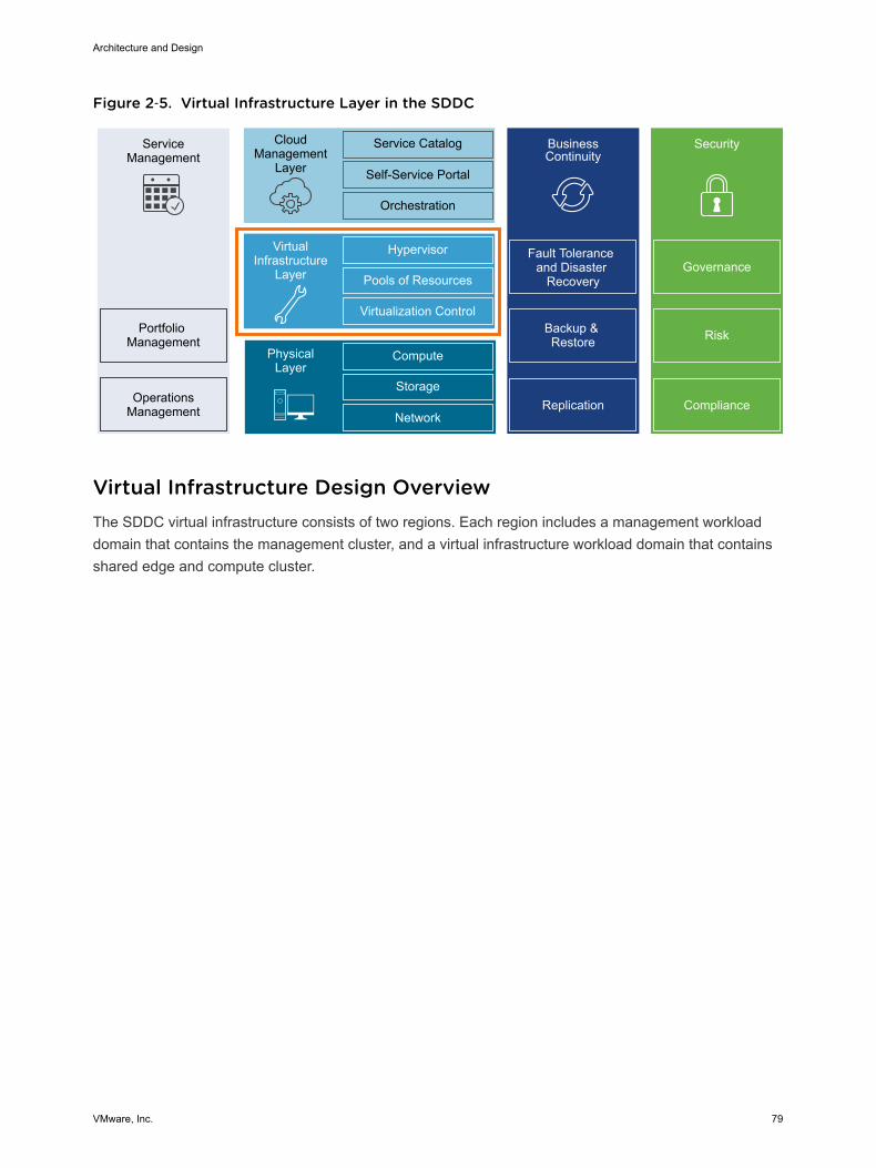
Figure 2‑5. Virtual Infrastructure Layer in the SDDC
ServiceManagement
Portfolio Management
OperationsManagement
CloudManagement
Layer
Service Catalog
Self-Service Portal
Orchestration
BusinessContinuity
Fault Tolerance and Disaster
Recovery
Backup & Restore
Hypervisor
Pools of Resources
Virtualization Control
VirtualInfrastructure
Layer
Compute
Storage
Network
PhysicalLayer
Security
Replication Compliance
Risk
Governance
Virtual Infrastructure Design OverviewThe SDDC virtual infrastructure consists of two regions. Each region includes a management workloaddomain that contains the management cluster, and a virtual infrastructure workload domain that containsshared edge and compute cluster.
Architecture and Design
VMware, Inc. 79
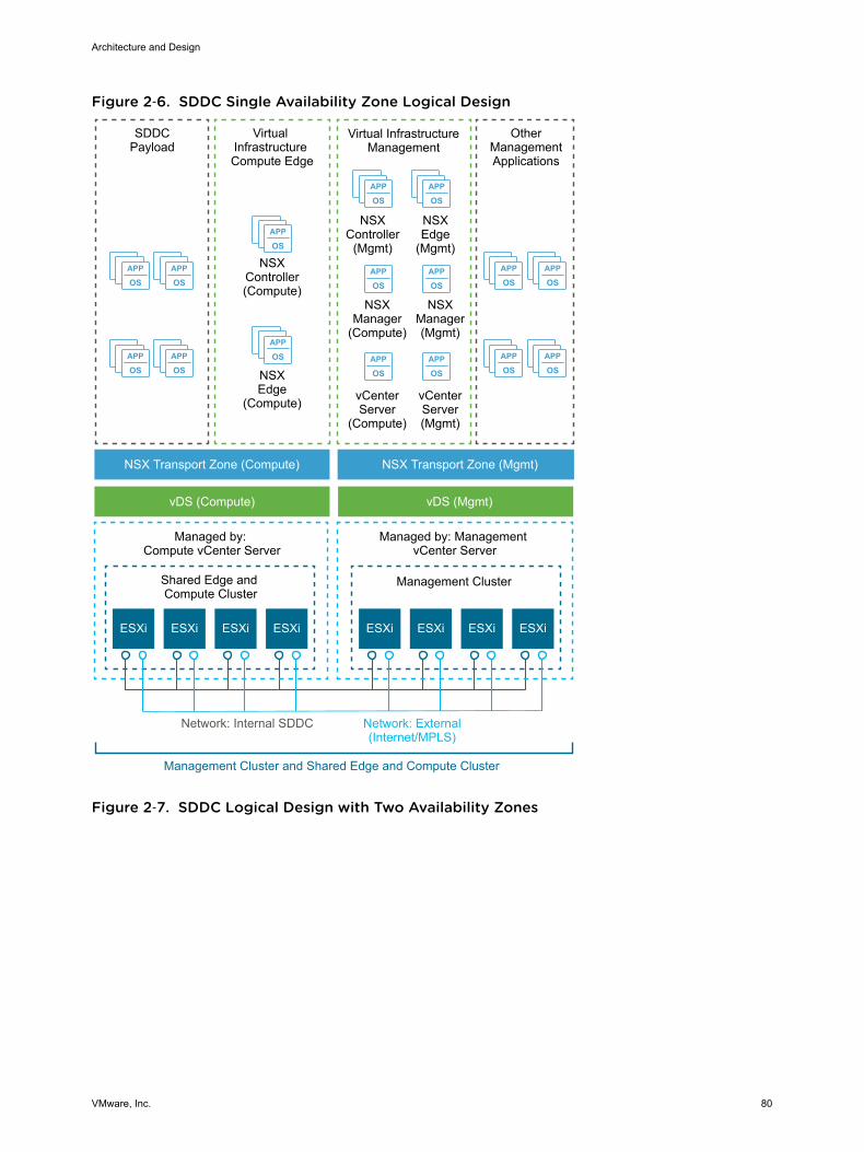
Figure 2‑6. SDDC Single Availability Zone Logical Design
APP
OSAPP
OS
APP
OSAPP
OS
APP
OSAPP
OS
APP
OSAPP
OS
APP
OS
APP
OS
APP
OSAPP
OS
APP
OSAPP
OS
APP
OSAPP
OS
Virtual InfrastructureManagement
NSXController
(Mgmt)
OtherManagementApplications
NSXEdge
(Mgmt)
NSXManager(Mgmt)
NSXManager
(Compute)
NSXEdge
(Compute)
NSXController(Compute)
ESXi ESXi ESXi ESXi ESXi ESXi
SDDCPayload
Virtual Infrastructure Compute Edge
NSX Transport Zone (Compute)
vDS (Compute) vDS (Mgmt)
NSX Transport Zone (Mgmt)
Shared Edge and Compute Cluster
Management Cluster
Managed by: Compute vCenter Server
Managed by: Management vCenter Server
Network: External(Internet/MPLS)
Network: Internal SDDC
Management Cluster and Shared Edge and Compute Cluster
vCenterServer(Mgmt)
vCenterServer
(Compute)
ESXi ESXi
Figure 2‑7. SDDC Logical Design with Two Availability Zones
Architecture and Design
VMware, Inc. 80
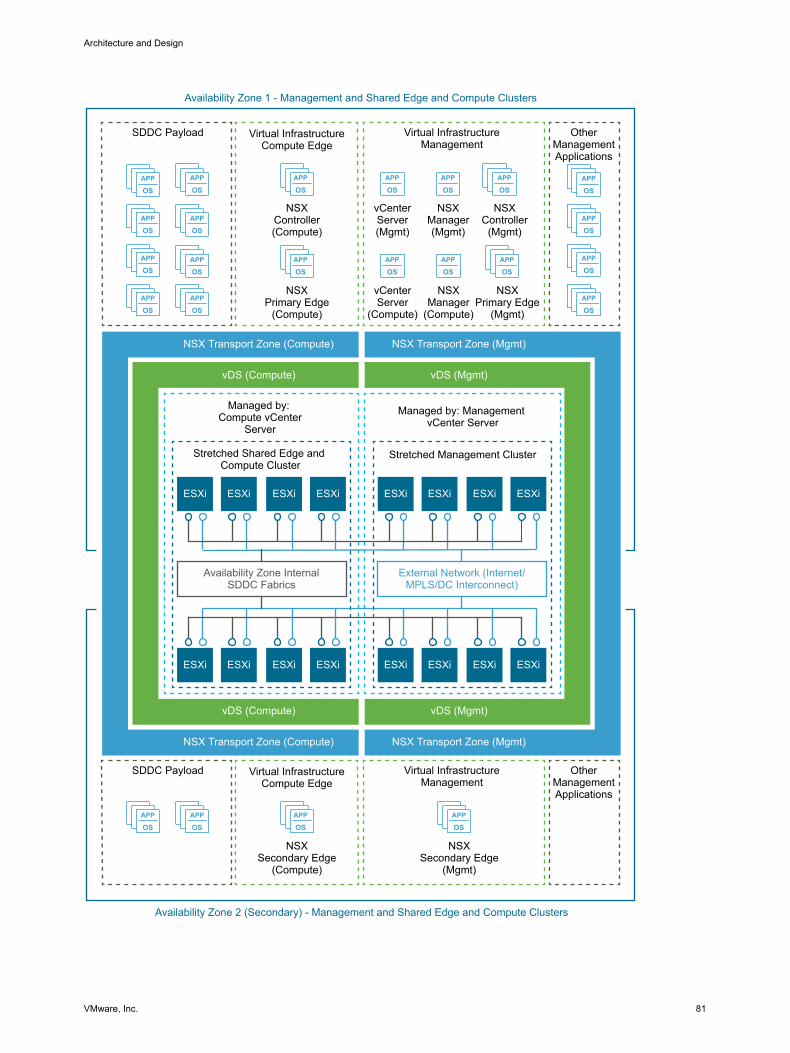
APP
OS
APP
OSAPP
OSAPP
OS
APP
OSAPP
OS
APP
OS
APP
OS
APP
OSAPP
OS
APP
OS
APP
OS
APP
OS
APP
OSAPP
OS
APP
OSAPP
OS
APP
OS
APP
OS
APP
OS
APP
OSAPP
OSAPP
OSAPP
OS
ESXi ESXi
Virtual InfrastructureCompute Edge
NSXPrimary Edge
(Compute)
NSXController(Compute)
ESXi
SDDC Payload
NSX Transport Zone (Compute)
vDS (Compute)
Stretched Shared Edge and Compute Cluster
Stretched Management Cluster
Managed by: Compute vCenter
Server
Managed by: Management vCenter Server
External Network (Internet/MPLS/DC Interconnect)
Availability Zone InternalSDDC Fabrics
Availability Zone 1 - Management and Shared Edge and Compute Clusters
ESXi
Virtual InfrastructureManagement
NSXController
(Mgmt)
NSXPrimary Edge
(Mgmt)
NSXManager(Mgmt)
NSXManager
(Compute)
vCenterServer(Mgmt)
vCenterServer
(Compute)
Availability Zone 2 (Secondary) - Management and Shared Edge and Compute Clusters
OtherManagementApplications
ESXiESXi ESXiESXi
ESXiESXi ESXiESXiESXiESXi ESXiESXi
NSX Transport Zone (Compute)
vDS (Compute)
NSX Transport Zone (Mgmt)
vDS (Mgmt)
NSX Transport Zone (Mgmt)
vDS (Mgmt)
Virtual InfrastructureCompute Edge
NSXSecondary Edge
(Compute)
SDDC Payload Virtual InfrastructureManagement
NSXSecondary Edge
(Mgmt)
OtherManagementApplications
Architecture and Design
VMware, Inc. 81
Management ClusterThe management cluster runs the virtual machines that manage the SDDC. These virtual machines hostvCenter Server, NSX Manager, NSX Controller, vRealize Operations, vRealize Log Insight, vRealizeAutomation, Site Recovery Manager and other shared management components. All management,monitoring, and infrastructure services are provisioned to a vSphere cluster which provides highavailability for these critical services. Permissions on the management cluster limit access to onlyadministrators. This protects the virtual machines running the management, monitoring, and infrastructureservices.
Shared Edge and Compute ClusterThe virtual infrastructure design uses a shared edge and compute cluster. The shared cluster combinesthe characteristics of typical edge and compute clusters into a single cluster. It is possible to separatethese in the future if required.
This cluster provides the following main functions:
n Supports on-ramp and off-ramp connectivity to physical networks
n Connects with VLANs in the physical world
n Hosts the SDDC tenant virtual machines
The shared edge and compute cluster connects the virtual networks (overlay networks) provided by NSXfor vSphere and the external networks. An SDDC can mix different types of compute-only clusters andprovide separate compute pools for different types of SLAs.
ESXi Design For the design of the configuration of the ESXi hosts, consider boot options, user access, and the virtualmachine swap configuration.
ESXi Hardware RequirementsFor the ESXi hardware requirements, see Physical Design Fundamentals.
ESXi Manual Install and Boot OptionsYou can install or boot ESXi from the following storage systems:
SATA disk drives SATA disk drives connected behind supported SAS controllers or supportedon-board SATA controllers.
Serial-attached SCSI(SAS) disk drives
Supported for ESXi installation
SAN Dedicated SAN disk on Fibre Channel or iSCSI.
Architecture and Design
VMware, Inc. 82
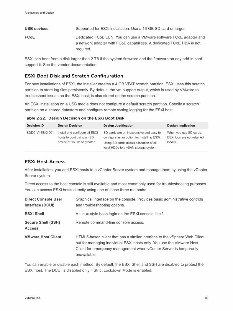
USB devices Supported for ESXi installation. Use a 16-GB SD card or larger.
FCoE Dedicated FCoE LUN. You can use a VMware software FCoE adapter anda network adapter with FCoE capabilities. A dedicated FCoE HBA is notrequired.
ESXi can boot from a disk larger than 2 TB if the system firmware and the firmware on any add-in cardsupport it. See the vendor documentation.
ESXi Boot Disk and Scratch ConfigurationFor new installations of ESXi, the installer creates a 4 GB VFAT scratch partition. ESXi uses this scratchpartition to store log files persistently. By default, the vm-support output, which is used by VMware totroubleshoot issues on the ESXi host, is also stored on the scratch partition.
An ESXi installation on a USB media does not configure a default scratch partition. Specify a scratchpartition on a shared datastore and configure remote syslog logging for the ESXi host.
Table 2‑22. Design Decision on the ESXi Boot Disk
Decision ID Design Decision Design Justification Design Implication
SDDC-VI-ESXi-001 Install and configure all ESXihosts to boot using an SDdevice of 16 GB or greater.
SD cards are an inexpensive and easy toconfigure as an option for installing ESXi.
Using SD cards allows allocation of alllocal HDDs to a vSAN storage system.
When you use SD cards,ESXi logs are not retainedlocally.
ESXi Host AccessAfter installation, you add ESXi hosts to a vCenter Server system and manage them by using the vCenterServer system.
Direct access to the host console is still available and most commonly used for troubleshooting purposes.You can access ESXi hosts directly using one of these three methods:
Direct Console UserInterface (DCUI)
Graphical interface on the console. Provides basic administrative controlsand troubleshooting options.
ESXi Shell A Linux-style bash login on the ESXi console itself.
Secure Shell (SSH)Access
Remote command-line console access.
VMware Host Client HTML5-based client that has a similar interface to the vSphere Web Clientbut for managing individual ESXi hosts only. You use the VMware HostClient for emergency management when vCenter Server is temporarilyunavailable
You can enable or disable each method. By default, the ESXi Shell and SSH are disabled to protect theESXi host. The DCUI is disabled only if Strict Lockdown Mode is enabled.
Architecture and Design
VMware, Inc. 83
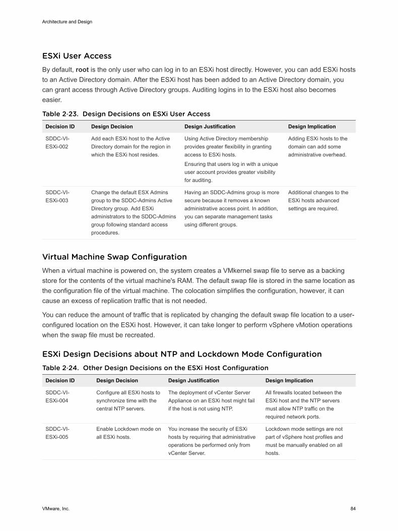
ESXi User AccessBy default, root is the only user who can log in to an ESXi host directly. However, you can add ESXi hoststo an Active Directory domain. After the ESXi host has been added to an Active Directory domain, youcan grant access through Active Directory groups. Auditing logins in to the ESXi host also becomeseasier.
Table 2‑23. Design Decisions on ESXi User Access
Decision ID Design Decision Design Justification Design Implication
SDDC-VI-ESXi-002
Add each ESXi host to the ActiveDirectory domain for the region inwhich the ESXi host resides.
Using Active Directory membershipprovides greater flexibility in grantingaccess to ESXi hosts.
Ensuring that users log in with a uniqueuser account provides greater visibilityfor auditing.
Adding ESXi hosts to thedomain can add someadministrative overhead.
SDDC-VI-ESXi-003
Change the default ESX Adminsgroup to the SDDC-Admins ActiveDirectory group. Add ESXiadministrators to the SDDC-Adminsgroup following standard accessprocedures.
Having an SDDC-Admins group is moresecure because it removes a knownadministrative access point. In addition,you can separate management tasksusing different groups.
Additional changes to theESXi hosts advancedsettings are required.
Virtual Machine Swap ConfigurationWhen a virtual machine is powered on, the system creates a VMkernel swap file to serve as a backingstore for the contents of the virtual machine's RAM. The default swap file is stored in the same location asthe configuration file of the virtual machine. The colocation simplifies the configuration, however, it cancause an excess of replication traffic that is not needed.
You can reduce the amount of traffic that is replicated by changing the default swap file location to a user-configured location on the ESXi host. However, it can take longer to perform vSphere vMotion operationswhen the swap file must be recreated.
ESXi Design Decisions about NTP and Lockdown Mode ConfigurationTable 2‑24. Other Design Decisions on the ESXi Host Configuration
Decision ID Design Decision Design Justification Design Implication
SDDC-VI-ESXi-004
Configure all ESXi hosts tosynchronize time with thecentral NTP servers.
The deployment of vCenter ServerAppliance on an ESXi host might failif the host is not using NTP.
All firewalls located between theESXi host and the NTP serversmust allow NTP traffic on therequired network ports.
SDDC-VI-ESXi-005
Enable Lockdown mode onall ESXi hosts.
You increase the security of ESXihosts by requiring that administrativeoperations be performed only fromvCenter Server.
Lockdown mode settings are notpart of vSphere host profiles andmust be manually enabled on allhosts.
Architecture and Design
VMware, Inc. 84
vCenter Server Design The vCenter Server design includes the design for both vCenter Server and Platform Services Controller.Determine the number of instances, their size, networking configuration, cluster layout, redundancy, andsecurity configuration.
A Platform Services Controller groups a set of infrastructure services including vCenter Single Sign-On,License service, Lookup Service, and VMware Certificate Authority (VMCA). You can deploy the PlatformServices Controller and the associated vCenter Server system on the same virtual machine(vCenterServer with an embedded Platform Services Controller) or on different virtual machines (vCenter Serverwith an external Platform Services Controller).
n vCenter Server Deployment
A vCenter Server deployment can consist of one or several vCenter Server and Platform ServicesController instances according to the scale, number of virtual machines and continuity requirementsfor your environment.
n vCenter Server Networking
As specified in the physical networking design, all vCenter Server systems must use static IPaddresses and host names. The IP addresses must have valid internal DNS registration includingreverse name resolution.
n vCenter Server Redundancy
Protecting the vCenter Server system is important because it is the central point of management andmonitoring for the SDDC. You protect vCenter Server according to the maximum downtime toleratedand whether failover automation is required.
n vCenter Server Appliance Sizing
You size resources and storage for the Management vCenter Server Appliance and the ComputevCenter Server Appliance to provide enough resources for accommodating the expected number ofmanagement virtual machines in the SDDC.
n vSphere Cluster Design
The cluster design must consider the workloads that the cluster handles. Different cluster types inthis design have different characteristics.
n vCenter Server Customization
vCenter Server supports a set of customization options, including monitoring, virtual machine faulttolerance, and so on.
n Use of TLS Certificates in vCenter Server
By default, vSphere uses TLS/SSL certificates that are signed by VMCA (VMware CertificateAuthority). These certificates are not trusted by end-user devices or browsers.
Architecture and Design
VMware, Inc. 85
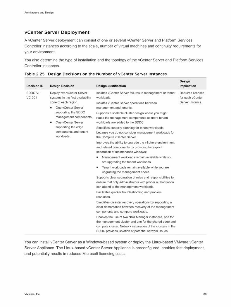
vCenter Server Deployment A vCenter Server deployment can consist of one or several vCenter Server and Platform ServicesController instances according to the scale, number of virtual machines and continuity requirements foryour environment.
You also determine the type of installation and the topology of the vCenter Server and Platform ServicesController instances.
Table 2‑25. Design Decisions on the Number of vCenter Server Instances
Decision ID Design Decision Design JustificationDesignImplication
SDDC-VI-VC-001
Deploy two vCenter Serversystems in the first availabilityzone of each region.n One vCenter Server
supporting the SDDCmanagement components.
n One vCenter Serversupporting the edgecomponents and tenantworkloads.
Isolates vCenter Server failures to management or tenantworkloads.
Isolates vCenter Server operations betweenmanagement and tenants.
Supports a scalable cluster design where you mightreuse the management components as more tenantworkloads are added to the SDDC.
Simplifies capacity planning for tenant workloadsbecause you do not consider management workloads forthe Compute vCenter Server.
Improves the ability to upgrade the vSphere environmentand related components by providing for explicitseparation of maintenance windows:n Management workloads remain available while you
are upgrading the tenant workloadsn Tenant workloads remain available while you are
upgrading the management nodes
Supports clear separation of roles and responsibilities toensure that only administrators with proper authorizationcan attend to the management workloads.
Facilitates quicker troubleshooting and problemresolution.
Simplifies disaster recovery operations by supporting aclear demarcation between recovery of the managementcomponents and compute workloads.
Enables the use of two NSX Manager instances, one forthe management cluster and one for the shared edge andcompute cluster. Network separation of the clusters in theSDDC provides isolation of potential network issues.
Requires licensesfor each vCenterServer instance.
You can install vCenter Server as a Windows-based system or deploy the Linux-based VMware vCenterServer Appliance. The Linux-based vCenter Server Appliance is preconfigured, enables fast deployment,and potentially results in reduced Microsoft licensing costs.
Architecture and Design
VMware, Inc. 86
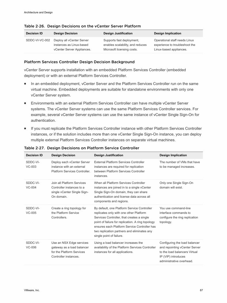
Table 2‑26. Design Decisions on the vCenter Server Platform
Decision ID Design Decision Design Justification Design Implication
SDDC-VI-VC-002 Deploy all vCenter Serverinstances as Linux-basedvCenter Server Appliances.
Supports fast deployment,enables scalability, and reducesMicrosoft licensing costs.
Operational staff needs Linuxexperience to troubleshoot theLinux-based appliances.
Platform Services Controller Design Decision Background
vCenter Server supports installation with an embedded Platform Services Controller (embeddeddeployment) or with an external Platform Services Controller.
n In an embedded deployment, vCenter Server and the Platform Services Controller run on the samevirtual machine. Embedded deployments are suitable for standalone environments with only onevCenter Server system.
n Environments with an external Platform Services Controller can have multiple vCenter Serversystems. The vCenter Server systems can use the same Platform Services Controller services. Forexample, several vCenter Server systems can use the same instance of vCenter Single Sign-On forauthentication.
n If you must replicate the Platform Services Controller instance with other Platform Services Controllerinstances, or if the solution includes more than one vCenter Single Sign-On instance, you can deploymultiple external Platform Services Controller instances on separate virtual machines.
Table 2‑27. Design Decisions on Platform Service Controller
Decision ID Design Decision Design Justification Design Implication
SDDC-VI-VC-003
Deploy each vCenter Serverinstance with an externalPlatform Services Controller.
External Platform Services Controllerinstances are required for replicationbetween Platform Services Controllerinstances.
The number of VMs that haveto be managed increases.
SDDC-VI-VC-004
Join all Platform ServicesController instances to asingle vCenter Single Sign-On domain.
When all Platform Services Controllerinstances are joined in to a single vCenterSingle Sign-On domain, they can shareauthentication and license data across allcomponents and regions.
Only one Single Sign-Ondomain will exist.
SDDC-VI-VC-005
Create a ring topology forthe Platform ServiceControllers.
By default, one Platform Service Controllerreplicates only with one other PlatformServices Controller, that creates a singlepoint of failure for replication. A ring topologyensures each Platform Service Controller hastwo replication partners and eliminates anysingle point of failure.
You use command-lineinterface commands toconfigure the ring replicationtopology.
SDDC-VI-VC-006
Use an NSX Edge servicesgateway as a load balancerfor the Platform ServicesController instances.
Using a load balancer increases theavailability of the Platform Services Controllerinstances for all applications.
Configuring the load balancerand repointing vCenter Serverto the load balancers VirtualIP (VIP) introducesadministrative overhead.
Architecture and Design
VMware, Inc. 87
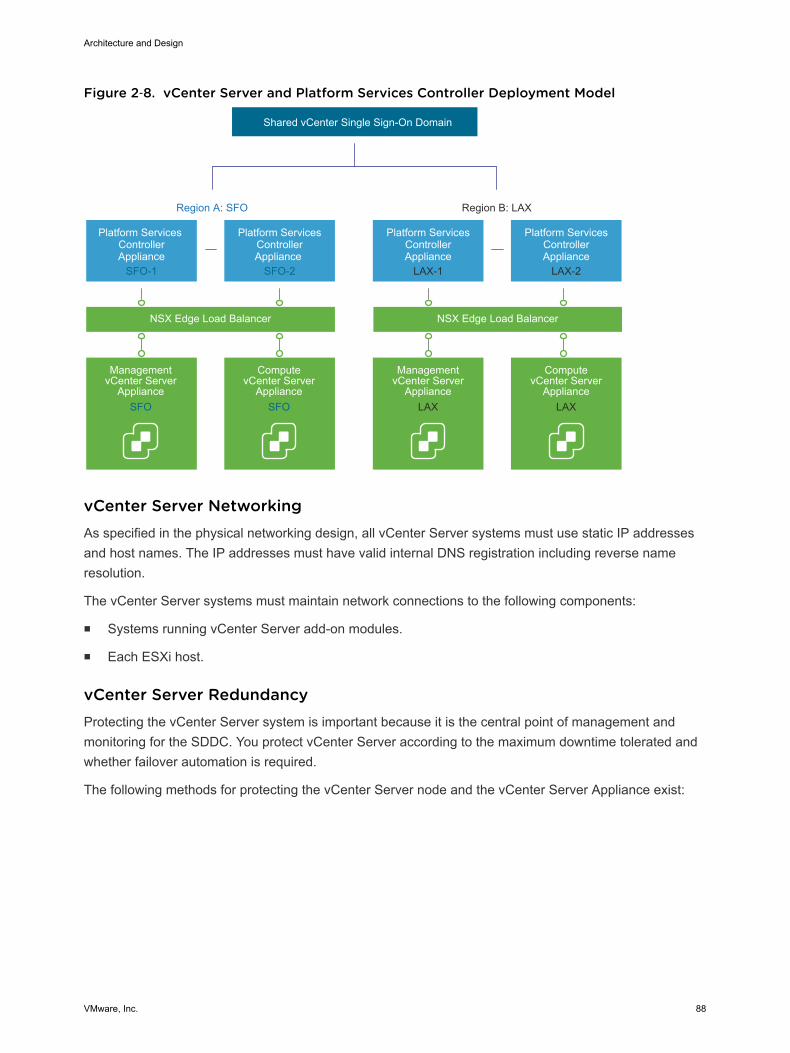
Figure 2‑8. vCenter Server and Platform Services Controller Deployment Model
Region A: SFO Region B: LAX
Platform Services ControllerAppliance
SFO-1
Management vCenter Server
Appliance
Shared vCenter Single Sign-On Domain
Platform ServicesControllerAppliance
SFO-2
NSX Edge Load Balancer NSX Edge Load Balancer
ComputevCenter Server
Appliance
Platform ServicesControllerAppliance
LAX-2
ComputevCenter Server
Appliance
Platform ServicesControllerAppliance
LAX-1
Management vCenter Server
Appliance LAX LAXSFO SFO
vCenter Server Networking As specified in the physical networking design, all vCenter Server systems must use static IP addressesand host names. The IP addresses must have valid internal DNS registration including reverse nameresolution.
The vCenter Server systems must maintain network connections to the following components:
n Systems running vCenter Server add-on modules.
n Each ESXi host.
vCenter Server Redundancy Protecting the vCenter Server system is important because it is the central point of management andmonitoring for the SDDC. You protect vCenter Server according to the maximum downtime tolerated andwhether failover automation is required.
The following methods for protecting the vCenter Server node and the vCenter Server Appliance exist:
Architecture and Design
VMware, Inc. 88
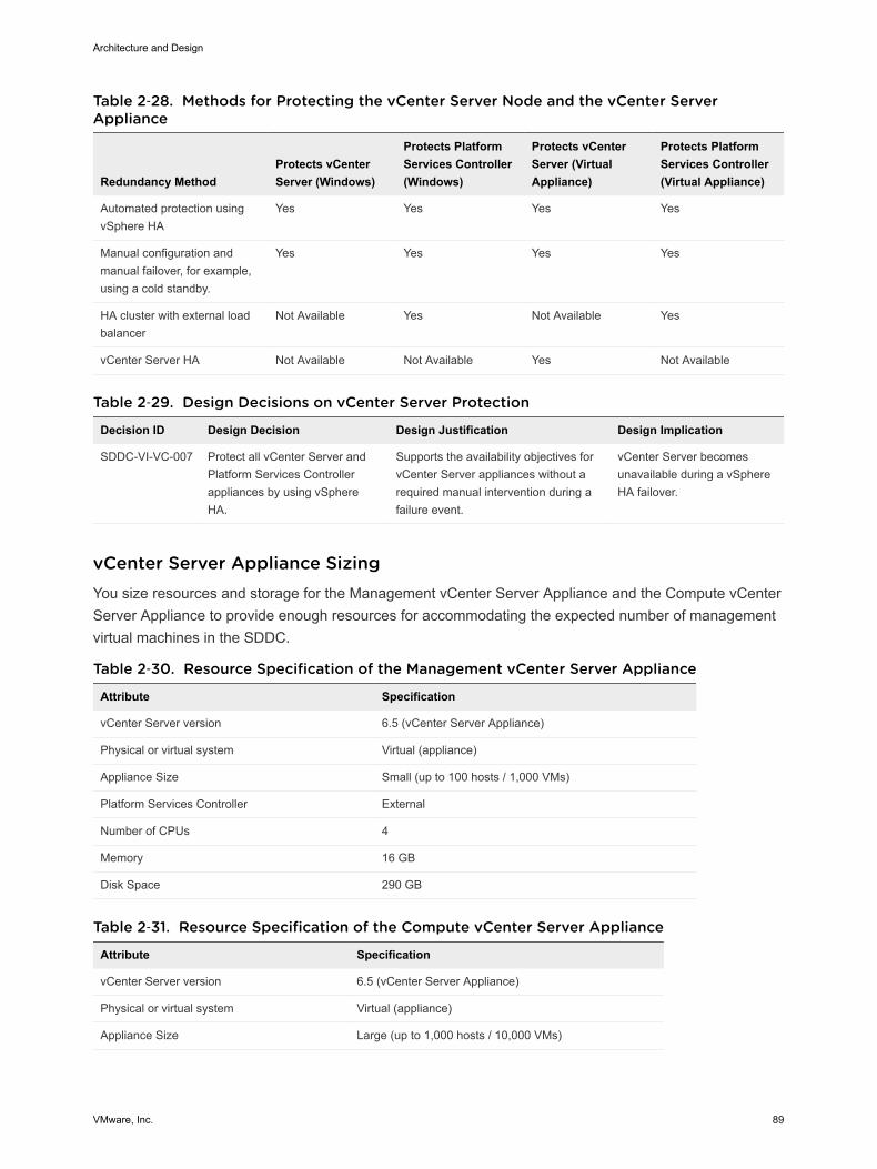
Table 2‑28. Methods for Protecting the vCenter Server Node and the vCenter ServerAppliance
Redundancy MethodProtects vCenterServer (Windows)
Protects PlatformServices Controller(Windows)
Protects vCenterServer (VirtualAppliance)
Protects PlatformServices Controller(Virtual Appliance)
Automated protection usingvSphere HA
Yes Yes Yes Yes
Manual configuration andmanual failover, for example,using a cold standby.
Yes Yes Yes Yes
HA cluster with external loadbalancer
Not Available Yes Not Available Yes
vCenter Server HA Not Available Not Available Yes Not Available
Table 2‑29. Design Decisions on vCenter Server Protection
Decision ID Design Decision Design Justification Design Implication
SDDC-VI-VC-007 Protect all vCenter Server andPlatform Services Controllerappliances by using vSphereHA.
Supports the availability objectives forvCenter Server appliances without arequired manual intervention during afailure event.
vCenter Server becomesunavailable during a vSphereHA failover.
vCenter Server Appliance Sizing You size resources and storage for the Management vCenter Server Appliance and the Compute vCenterServer Appliance to provide enough resources for accommodating the expected number of managementvirtual machines in the SDDC.
Table 2‑30. Resource Specification of the Management vCenter Server Appliance
Attribute Specification
vCenter Server version 6.5 (vCenter Server Appliance)
Physical or virtual system Virtual (appliance)
Appliance Size Small (up to 100 hosts / 1,000 VMs)
Platform Services Controller External
Number of CPUs 4
Memory 16 GB
Disk Space 290 GB
Table 2‑31. Resource Specification of the Compute vCenter Server Appliance
Attribute Specification
vCenter Server version 6.5 (vCenter Server Appliance)
Physical or virtual system Virtual (appliance)
Appliance Size Large (up to 1,000 hosts / 10,000 VMs)
Architecture and Design
VMware, Inc. 89
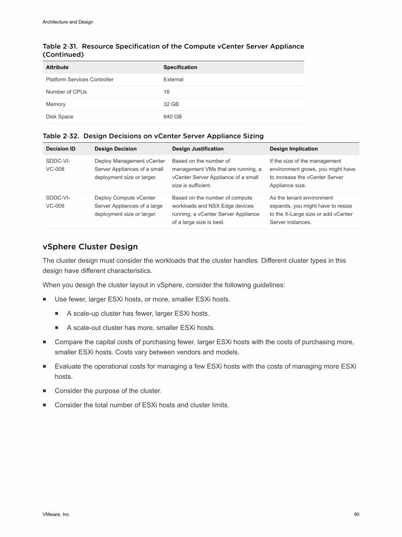
Table 2‑31. Resource Specification of the Compute vCenter Server Appliance(Continued)
Attribute Specification
Platform Services Controller External
Number of CPUs 16
Memory 32 GB
Disk Space 640 GB
Table 2‑32. Design Decisions on vCenter Server Appliance Sizing
Decision ID Design Decision Design Justification Design Implication
SDDC-VI-VC-008
Deploy Management vCenterServer Appliances of a smalldeployment size or larger.
Based on the number ofmanagement VMs that are running, avCenter Server Appliance of a smallsize is sufficient.
If the size of the managementenvironment grows, you might haveto increase the vCenter ServerAppliance size.
SDDC-VI-VC-009
Deploy Compute vCenterServer Appliances of a largedeployment size or larger.
Based on the number of computeworkloads and NSX Edge devicesrunning, a vCenter Server Applianceof a large size is best.
As the tenant environmentexpands, you might have to resizeto the X-Large size or add vCenterServer instances.
vSphere Cluster Design The cluster design must consider the workloads that the cluster handles. Different cluster types in thisdesign have different characteristics.
When you design the cluster layout in vSphere, consider the following guidelines:
n Use fewer, larger ESXi hosts, or more, smaller ESXi hosts.
n A scale-up cluster has fewer, larger ESXi hosts.
n A scale-out cluster has more, smaller ESXi hosts.
n Compare the capital costs of purchasing fewer, larger ESXi hosts with the costs of purchasing more,smaller ESXi hosts. Costs vary between vendors and models.
n Evaluate the operational costs for managing a few ESXi hosts with the costs of managing more ESXihosts.
n Consider the purpose of the cluster.
n Consider the total number of ESXi hosts and cluster limits.
Architecture and Design
VMware, Inc. 90
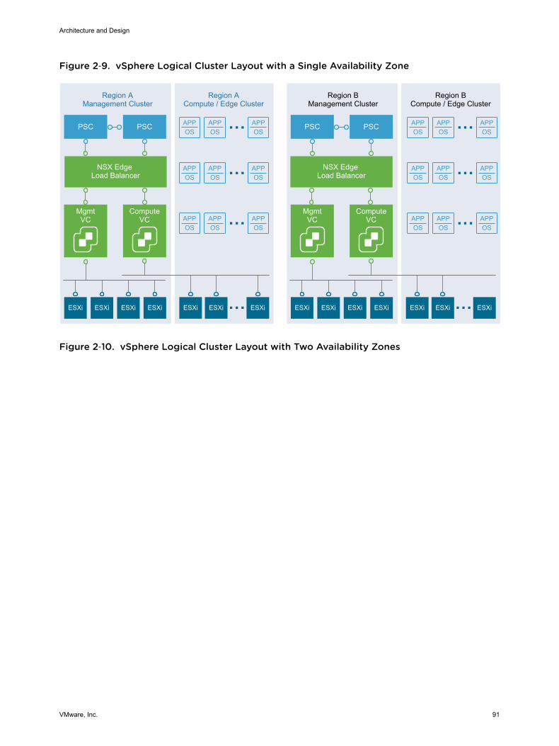
Figure 2‑9. vSphere Logical Cluster Layout with a Single Availability Zone
APPOS
APPOS
APPOS
APPOS
APPOS
APPOS
APPOS
APPOS
APPOS
APPOS
APPOS
APPOS
APPOS
APPOS
APPOS
APPOS
APPOS
APPOS
MgmtVC
Region AManagement Cluster
ESXi ESXi ESXi ESXi ESXi ESXi ESXi
Region ACompute / Edge Cluster
Region BManagement Cluster
Region BCompute / Edge Cluster
PSC
NSX Edge Load Balancer
NSX Edge Load Balancer
ComputeVC
PSC
MgmtVC
ESXi ESXi ESXi ESXi ESXi ESXi ESXi
PSC
ComputeVC
PSC
Figure 2‑10. vSphere Logical Cluster Layout with Two Availability Zones
Architecture and Design
VMware, Inc. 91
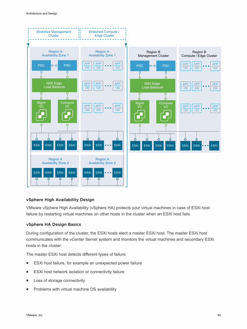
APPOS
APPOS
APPOS
APPOS
APPOS
APPOS
APPOS
APPOS
APPOS
APPOS
APPOS
APPOS
APPOS
APPOS
APPOS
APPOS
APPOS
APPOS
MgmtVC
Region AAvailability Zone 1
ESXi ESXi ESXi ESXi ESXi ESXi ESXi
Region AAvailability Zone 1
Region BManagement Cluster
Region BCompute / Edge Cluster
PSC
NSX Edge Load Balancer
NSX Edge Load Balancer
ComputeVC
PSC
MgmtVC
ESXi ESXi ESXi ESXi ESXi ESXi ESXi
PSC
ComputeVC
PSC
ESXi ESXi ESXi ESXi ESXi ESXi ESXi
Region AAvailability Zone 2
Region AAvailability Zone 2
Stretched ManagementCluster
Stretched Compute / Edge Cluster
vSphere High Availability Design
VMware vSphere High Availability (vSphere HA) protects your virtual machines in case of ESXi hostfailure by restarting virtual machines on other hosts in the cluster when an ESXi host fails.
vSphere HA Design Basics
During configuration of the cluster, the ESXi hosts elect a master ESXi host. The master ESXi hostcommunicates with the vCenter Server system and monitors the virtual machines and secondary ESXihosts in the cluster.
The master ESXi host detects different types of failure:
n ESXi host failure, for example an unexpected power failure
n ESXi host network isolation or connectivity failure
n Loss of storage connectivity
n Problems with virtual machine OS availability
Architecture and Design
VMware, Inc. 92
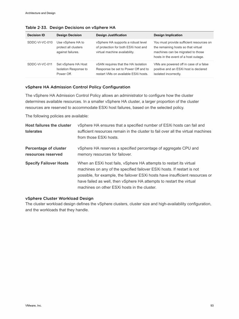
Table 2‑33. Design Decisions on vSphere HA
Decision ID Design Decision Design Justification Design Implication
SDDC-VI-VC-010 Use vSphere HA toprotect all clustersagainst failures.
vSphere HA supports a robust levelof protection for both ESXi host andvirtual machine availability.
You must provide sufficient resources onthe remaining hosts so that virtualmachines can be migrated to thosehosts in the event of a host outage.
SDDC-VI-VC-011 Set vSphere HA HostIsolation Response toPower Off.
vSAN requires that the HA IsolationResponse be set to Power Off and torestart VMs on available ESXi hosts.
VMs are powered off in case of a falsepositive and an ESXi host is declaredisolated incorrectly.
vSphere HA Admission Control Policy Configuration
The vSphere HA Admission Control Policy allows an administrator to configure how the clusterdetermines available resources. In a smaller vSphere HA cluster, a larger proportion of the clusterresources are reserved to accommodate ESXi host failures, based on the selected policy.
The following policies are available:
Host failures the clustertolerates
vSphere HA ensures that a specified number of ESXi hosts can fail andsufficient resources remain in the cluster to fail over all the virtual machinesfrom those ESXi hosts.
Percentage of clusterresources reserved
vSphere HA reserves a specified percentage of aggregate CPU andmemory resources for failover.
Specify Failover Hosts When an ESXi host fails, vSphere HA attempts to restart its virtualmachines on any of the specified failover ESXi hosts. If restart is notpossible, for example, the failover ESXi hosts have insufficient resources orhave failed as well, then vSphere HA attempts to restart the virtualmachines on other ESXi hosts in the cluster.
vSphere Cluster Workload Design The cluster workload design defines the vSphere clusters, cluster size and high-availability configuration,and the workloads that they handle.
Architecture and Design
VMware, Inc. 93
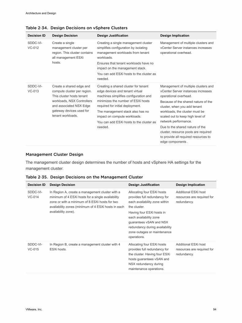
Table 2‑34. Design Decisions on vSphere Clusters
Decision ID Design Decision Design Justification Design Implication
SDDC-VI-VC-012
Create a singlemanagement cluster perregion. This cluster containsall management ESXihosts.
Creating a single management clustersimplifies configuration by isolatingmanagement workloads from tenantworkloads.
Ensures that tenant workloads have noimpact on the management stack.
You can add ESXi hosts to the cluster asneeded.
Management of multiple clusters andvCenter Server instances increasesoperational overhead.
SDDC-VI-VC-013
Create a shared edge andcompute cluster per region.This cluster hosts tenantworkloads, NSX Controllersand associated NSX Edgegateway devices used fortenant workloads.
Creating a shared cluster for tenantedge devices and tenant virtualmachines simplifies configuration andminimizes the number of ESXi hostsrequired for initial deployment.
The management stack also has noimpact on compute workloads.
You can add ESXi hosts to the cluster asneeded.
Management of multiple clusters andvCenter Server instances increasesoperational overhead.
Because of the shared nature of thecluster, when you add tenantworkloads, the cluster must bescaled out to keep high level ofnetwork performance.
Due to the shared nature of thecluster, resource pools are requiredto provide all required resources toedge components .
Management Cluster Design
The management cluster design determines the number of hosts and vSphere HA settings for themanagement cluster.
Table 2‑35. Design Decisions on the Management Cluster
Decision ID Design Decision Design Justification Design Implication
SDDC-VI-VC-014
In Region A, create a management cluster with aminimum of 4 ESXi hosts for a single availabilityzone or with a minimum of 8 ESXi hosts for twoavailability zones (minimum of 4 ESXi hosts in eachavailability zone).
Allocating four ESXi hostsprovides full redundancy foreach availability zone withinthe cluster.
Having four ESXi hosts ineach availability zoneguarantees vSAN and NSXredundancy during availabilityzone outages or maintenanceoperations.
Additional ESXi hostresources are required forredundancy.
SDDC-VI-VC-015
In Region B, create a management cluster with 4ESXi hosts.
Allocating four ESXi hostsprovides full redundancy forthe cluster. Having four ESXihosts guarantees vSAN andNSX redundancy duringmaintenance operations.
Additional ESXi hostresources are required forredundancy.
Architecture and Design
VMware, Inc. 94
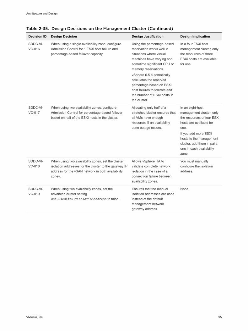
Table 2‑35. Design Decisions on the Management Cluster (Continued)
Decision ID Design Decision Design Justification Design Implication
SDDC-VI-VC-016
When using a single availability zone, configureAdmission Control for 1 ESXi host failure andpercentage-based failover capacity.
Using the percentage-basedreservation works well insituations where virtualmachines have varying andsometime significant CPU ormemory reservations.
vSphere 6.5 automaticallycalculates the reservedpercentage based on ESXihost failures to tolerate andthe number of ESXi hosts inthe cluster.
In a four ESXi hostmanagement cluster, onlythe resources of threeESXi hosts are availablefor use.
SDDC-VI-VC-017
When using two availability zones, configureAdmission Control for percentage-based failoverbased on half of the ESXi hosts in the cluster.
Allocating only half of astretched cluster ensures thatall VMs have enoughresources if an availabilityzone outage occurs.
In an eight-hostmanagement cluster, onlythe resources of four ESXihosts are available foruse.
If you add more ESXihosts to the managementcluster, add them in pairs,one in each availabilityzone.
SDDC-VI-VC-018
When using two availability zones, set the clusterisolation addresses for the cluster to the gateway IPaddress for the vSAN network in both availabilityzones.
Allows vSphere HA tovalidate complete networkisolation in the case of aconnection failure betweenavailability zones.
You must manuallyconfigure the isolationaddress.
SDDC-VI-VC-019
When using two availability zones, set theadvanced cluster settingdas.usedefaultisolationaddress to false.
Ensures that the manualisolation addresses are usedinstead of the defaultmanagement networkgateway address.
None.
Architecture and Design
VMware, Inc. 95
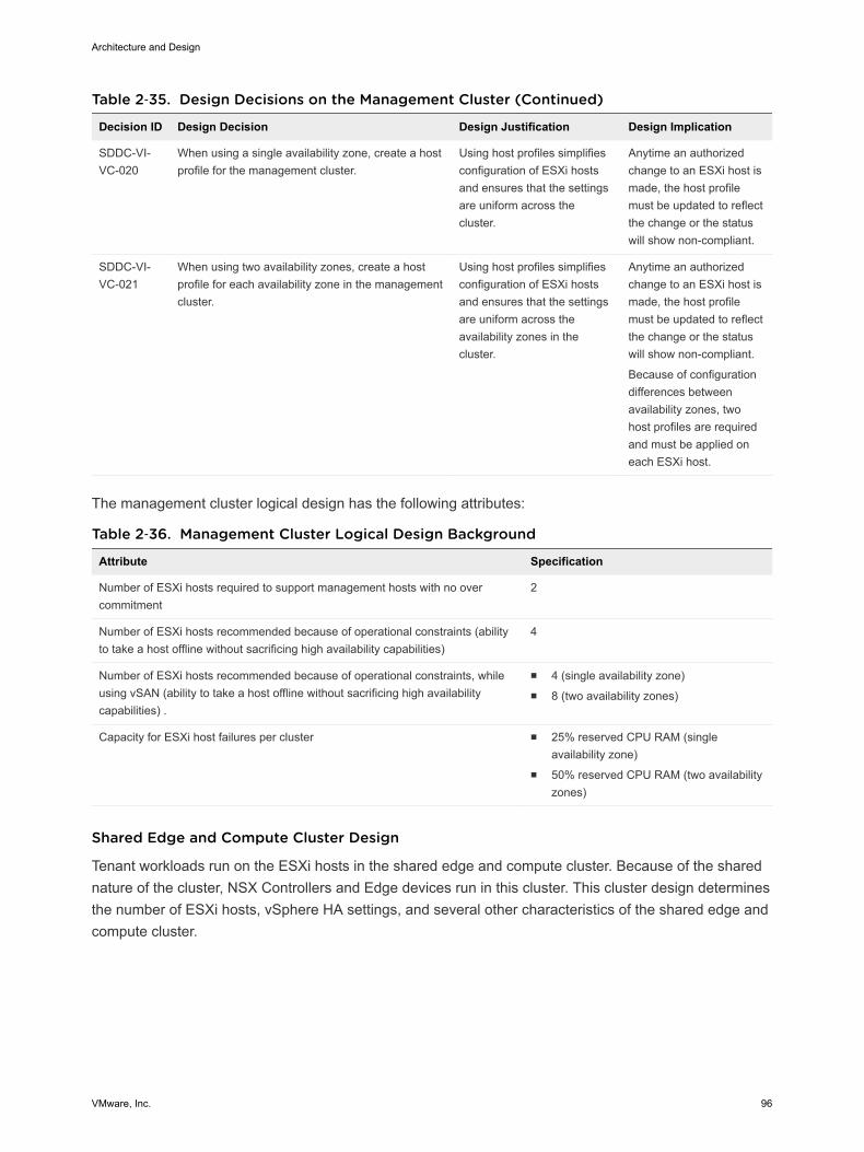
Table 2‑35. Design Decisions on the Management Cluster (Continued)
Decision ID Design Decision Design Justification Design Implication
SDDC-VI-VC-020
When using a single availability zone, create a hostprofile for the management cluster.
Using host profiles simplifiesconfiguration of ESXi hostsand ensures that the settingsare uniform across thecluster.
Anytime an authorizedchange to an ESXi host ismade, the host profilemust be updated to reflectthe change or the statuswill show non-compliant.
SDDC-VI-VC-021
When using two availability zones, create a hostprofile for each availability zone in the managementcluster.
Using host profiles simplifiesconfiguration of ESXi hostsand ensures that the settingsare uniform across theavailability zones in thecluster.
Anytime an authorizedchange to an ESXi host ismade, the host profilemust be updated to reflectthe change or the statuswill show non-compliant.
Because of configurationdifferences betweenavailability zones, twohost profiles are requiredand must be applied oneach ESXi host.
The management cluster logical design has the following attributes:
Table 2‑36. Management Cluster Logical Design Background
Attribute Specification
Number of ESXi hosts required to support management hosts with no overcommitment
2
Number of ESXi hosts recommended because of operational constraints (abilityto take a host offline without sacrificing high availability capabilities)
4
Number of ESXi hosts recommended because of operational constraints, whileusing vSAN (ability to take a host offline without sacrificing high availabilitycapabilities) .
n 4 (single availability zone)n 8 (two availability zones)
Capacity for ESXi host failures per cluster n 25% reserved CPU RAM (singleavailability zone)
n 50% reserved CPU RAM (two availabilityzones)
Shared Edge and Compute Cluster Design
Tenant workloads run on the ESXi hosts in the shared edge and compute cluster. Because of the sharednature of the cluster, NSX Controllers and Edge devices run in this cluster. This cluster design determinesthe number of ESXi hosts, vSphere HA settings, and several other characteristics of the shared edge andcompute cluster.
Architecture and Design
VMware, Inc. 96
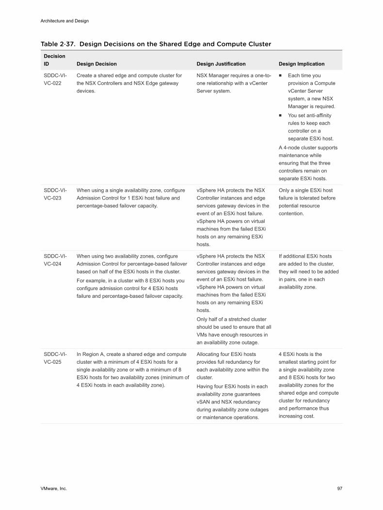
Table 2‑37. Design Decisions on the Shared Edge and Compute Cluster
DecisionID Design Decision Design Justification Design Implication
SDDC-VI-VC-022
Create a shared edge and compute cluster forthe NSX Controllers and NSX Edge gatewaydevices.
NSX Manager requires a one-to-one relationship with a vCenterServer system.
n Each time youprovision a ComputevCenter Serversystem, a new NSXManager is required.
n You set anti-affinityrules to keep eachcontroller on aseparate ESXi host.
A 4-node cluster supportsmaintenance whileensuring that the threecontrollers remain onseparate ESXi hosts.
SDDC-VI-VC-023
When using a single availability zone, configureAdmission Control for 1 ESXi host failure andpercentage-based failover capacity.
vSphere HA protects the NSXController instances and edgeservices gateway devices in theevent of an ESXi host failure.vSphere HA powers on virtualmachines from the failed ESXihosts on any remaining ESXihosts.
Only a single ESXi hostfailure is tolerated beforepotential resourcecontention.
SDDC-VI-VC-024
When using two availability zones, configureAdmission Control for percentage-based failoverbased on half of the ESXi hosts in the cluster.
For example, in a cluster with 8 ESXi hosts youconfigure admission control for 4 ESXi hostsfailure and percentage-based failover capacity.
vSphere HA protects the NSXController instances and edgeservices gateway devices in theevent of an ESXi host failure.vSphere HA powers on virtualmachines from the failed ESXihosts on any remaining ESXihosts.
Only half of a stretched clustershould be used to ensure that allVMs have enough resources inan availability zone outage.
If additional ESXi hostsare added to the cluster,they will need to be addedin pairs, one in eachavailability zone.
SDDC-VI-VC-025
In Region A, create a shared edge and computecluster with a minimum of 4 ESXi hosts for asingle availability zone or with a minimum of 8ESXi hosts for two availability zones (minimum of4 ESXi hosts in each availability zone).
Allocating four ESXi hostsprovides full redundancy foreach availability zone within thecluster.
Having four ESXi hosts in eachavailability zone guaranteesvSAN and NSX redundancyduring availability zone outagesor maintenance operations.
4 ESXi hosts is thesmallest starting point fora single availability zoneand 8 ESXi hosts for twoavailability zones for theshared edge and computecluster for redundancyand performance thusincreasing cost.
Architecture and Design
VMware, Inc. 97
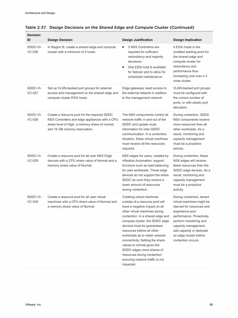
Table 2‑37. Design Decisions on the Shared Edge and Compute Cluster (Continued)
DecisionID Design Decision Design Justification Design Implication
SDDC-VI-VC-026
In Region B, create a shared edge and computecluster with a minimum of 4 hosts.
n 3 NSX Controllers arerequired for sufficientredundancy and majoritydecisions.
n One ESXi host is availablefor failover and to allow forscheduled maintenance.
4 ESXi hosts is thesmallest starting point forthe shared edge andcompute cluster forredundancy andperformance thusincreasing cost over a 3node cluster.
SDDC-VI-VC-027
Set up VLAN-backed port groups for externalaccess and management on the shared edge andcompute cluster ESXi hosts.
Edge gateways need access tothe external network in additionto the management network.
VLAN-backed port groupsmust be configured withthe correct number ofports, or with elastic portallocation.
SDDC-VI-VC-028
Create a resource pool for the required SDDCNSX Controllers and edge appliances with a CPUshare level of High, a memory share of normal,and 16 GB memory reservation.
The NSX components control allnetwork traffic in and out of theSDDC and update routeinformation for inter-SDDCcommunication. In a contentionsituation, these virtual machinesmust receive all the resourcesrequired.
During contention, SDDCNSX components receivemore resources than allother workloads. As aresult, monitoring andcapacity managementmust be a proactiveactivity.
SDDC-VI-VC-029
Create a resource pool for all user NSX Edgedevices with a CPU share value of Normal and amemory share value of Normal.
NSX edges for users, created byvRealize Automation, supportfunctions such as load balancingfor user workloads. These edgedevices do not support the entireSDDC as such they receive alower amount of resourcesduring contention.
During contention, theseNSX edges will receivefewer resources than theSDDC edge devices. As aresult, monitoring andcapacity managementmust be a proactiveactivity.
SDDC-VI-VC-030
Create a resource pool for all user virtualmachines with a CPU share value of Normal anda memory share value of Normal.
Creating virtual machinesoutside of a resource pool willhave a negative impact on allother virtual machines duringcontention. In a shared edge andcompute cluster, the SDDC edgedevices must be guaranteedresources before all otherworkloads as to retain networkconnectivity. Setting the sharevalues to normal gives theSDDC edges more shares ofresources during contentionensuring network traffic is notimpacted.
During contention, tenantvirtual machines might bestarved for resources andexperience poorperformance. Proactivelyperform monitoring andcapacity management,add capacity or dedicatean edge cluster beforecontention occurs.
Architecture and Design
VMware, Inc. 98
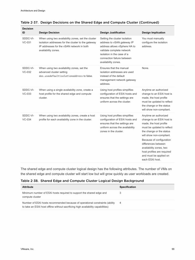
Table 2‑37. Design Decisions on the Shared Edge and Compute Cluster (Continued)
DecisionID Design Decision Design Justification Design Implication
SDDC-VI-VC-031
When using two availability zones, set the clusterisolation addresses for the cluster to the gatewayIP addresses for the vSAN network in bothavailability zones.
Setting the cluster isolationaddress to vSAN gateway IPaddress allows vSphere HA tovalidate complete networkisolation in the case of aconnection failure betweenavailability zones.
You must manuallyconfigure the isolationaddress.
SDDC-VI-VC-032
When using two availability zones, set theadvanced cluster settingdas.usedefaultisolationaddress to false.
Ensures that the manualisolation addresses are usedinstead of the defaultmanagement network gatewayaddress.
None.
SDDC-VI-VC-033
When using a single availability zone, create ahost profile for the shared edge and computecluster.
Using host profiles simplifiesconfiguration of ESXi hosts andensures that the settings areuniform across the cluster.
Anytime an authorizedchange to an ESXi host ismade, the host profilemust be updated to reflectthe change or the statuswill show non-compliant.
SDDC-VI-VC-034
When using two availability zones, create a hostprofile for each availability zone in the cluster.
Using host profiles simplifiesconfiguration of ESXi hosts andensures that the settings areuniform across the availabilityzones in the cluster.
Anytime an authorizedchange to an ESXi host ismade, the host profilemust be updated to reflectthe change or the statuswill show non-compliant.
Because of configurationdifferences betweenavailability zones, twohost profiles are requiredand must be applied oneach ESXi host.
The shared edge and compute cluster logical design has the following attributes. The number of VMs onthe shared edge and compute cluster will start low but will grow quickly as user workloads are created.
Table 2‑38. Shared Edge and Compute Cluster Logical Design Background
Attribute Specification
Minimum number of ESXi hosts required to support the shared edge andcompute cluster
3
Number of ESXi hosts recommended because of operational constraints (abilityto take an ESXi host offline without sacrificing high availability capabilities)
4
Architecture and Design
VMware, Inc. 99
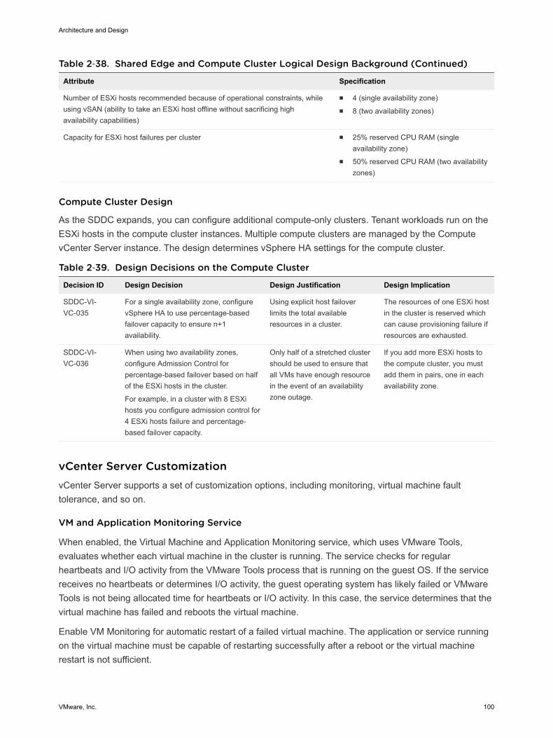
Table 2‑38. Shared Edge and Compute Cluster Logical Design Background (Continued)
Attribute Specification
Number of ESXi hosts recommended because of operational constraints, whileusing vSAN (ability to take an ESXi host offline without sacrificing highavailability capabilities)
n 4 (single availability zone)n 8 (two availability zones)
Capacity for ESXi host failures per cluster n 25% reserved CPU RAM (singleavailability zone)
n 50% reserved CPU RAM (two availabilityzones)
Compute Cluster Design
As the SDDC expands, you can configure additional compute-only clusters. Tenant workloads run on theESXi hosts in the compute cluster instances. Multiple compute clusters are managed by the ComputevCenter Server instance. The design determines vSphere HA settings for the compute cluster.
Table 2‑39. Design Decisions on the Compute Cluster
Decision ID Design Decision Design Justification Design Implication
SDDC-VI-VC-035
For a single availability zone, configurevSphere HA to use percentage-basedfailover capacity to ensure n+1availability.
Using explicit host failoverlimits the total availableresources in a cluster.
The resources of one ESXi hostin the cluster is reserved whichcan cause provisioning failure ifresources are exhausted.
SDDC-VI-VC-036
When using two availability zones,configure Admission Control forpercentage-based failover based on halfof the ESXi hosts in the cluster.
For example, in a cluster with 8 ESXihosts you configure admission control for4 ESXi hosts failure and percentage-based failover capacity.
Only half of a stretched clustershould be used to ensure thatall VMs have enough resourcein the event of an availabilityzone outage.
If you add more ESXi hosts tothe compute cluster, you mustadd them in pairs, one in eachavailability zone.
vCenter Server Customization vCenter Server supports a set of customization options, including monitoring, virtual machine faulttolerance, and so on.
VM and Application Monitoring Service
When enabled, the Virtual Machine and Application Monitoring service, which uses VMware Tools,evaluates whether each virtual machine in the cluster is running. The service checks for regularheartbeats and I/O activity from the VMware Tools process that is running on the guest OS. If the servicereceives no heartbeats or determines I/O activity, the guest operating system has likely failed or VMwareTools is not being allocated time for heartbeats or I/O activity. In this case, the service determines that thevirtual machine has failed and reboots the virtual machine.
Enable VM Monitoring for automatic restart of a failed virtual machine. The application or service runningon the virtual machine must be capable of restarting successfully after a reboot or the virtual machinerestart is not sufficient.
Architecture and Design
VMware, Inc. 100

Table 2‑40. Design Decisions on Monitoring and Startup Order Configuration for VirtualMachines
Decision ID Design Decision Design Justification Design Implication
SDDC-VI-VC-037 Enable VM Monitoring for eachcluster.
VM Monitoring provides in-guestprotection for most VM workloads.
None.
SDDC-VI-VC-038 Create virtual machine groups foruse in startup rules in themanagement and shared edgeand compute clusters.
By creating virtual machine groups,you can use rules to configure thestartup order of the SDDCmanagement components.
Creating the groups is amanual task and addsadministrative overhead.
SDDC-VI-VC-039 Create virtual machine rules tospecify the startup order of theSDDC management components.
Rules enforce the startup order ofvirtual machine groups, hence, thestartup order of the SDDCmanagement components.
Creating the rules is amanual task and addsadministrative overhead.
VMware vSphere Distributed Resource Scheduling (DRS)
vSphere Distributed Resource Scheduling provides load balancing of a cluster by migrating workloadsfrom heavily loaded ESXi hosts to less utilized ESXi hosts in the cluster. vSphere DRS supports manualand automatic modes.
Manual Recommendations are made but an administrator needs to confirm thechanges.
Automatic Automatic management can be set to five different levels. At the lowestsetting, workloads are placed automatically at power-on and only migratedto fulfill certain criteria, such as entering maintenance mode. At the highestlevel, any migration that would provide a slight improvement in balancing isperformed.
When using two availability zones, enable vSphere DRS to create VM/Host group affinity rules for initialplacement of VMs and impacting read locality. In this way, you avoid unnecessary vSphere vMotionmigration of VMs between availability zones. Because the stretched cluster is still a single cluster,vSphere DRS is unaware that it stretches across different physical locations. As result, it might decide tomove virtual machines between them. By using VM/Host group affinity rules, you can pin virtual machinesto an availability zone. If a virtual machine, VM1, that resides in availability zone 1 moves freely acrossavailability zones, VM1 could end up on availability zone 2. Because vSAN stretched clusters implementread locality, the cache on availability zone 1 is warm whereas the cache in availability zone 2 is cold.This may impact the performance of VM1 until the cache in availability zone 2 has been warmed.
Architecture and Design
VMware, Inc. 101
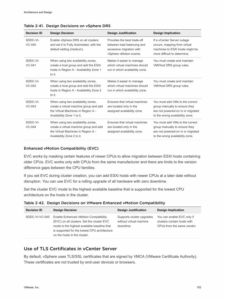
Table 2‑41. Design Decisions on vSphere DRS
Decision ID Design Decision Design Justification Design Implication
SDDC-VI-VC-040
Enable vSphere DRS on all clustersand set it to Fully Automated, with thedefault setting (medium).
Provides the best trade-offbetween load balancing andexcessive migration withvSphere vMotion events.
If a vCenter Server outageoccurs, mapping from virtualmachines to ESXi hosts might bemore difficult to determine.
SDDC-VI-VC-041
When using two availability zones,create a host group and add the ESXihosts in Region A - Availability Zone 1to it.
Makes it easier to managewhich virtual machines shouldrun in which availability zone.
You must create and maintainVM/Host DRS group rules.
SDDC-VI-VC-042
When using two availability zones,create a host group and add the ESXihosts in Region A - Availability Zone 2to it.
Makes it easier to managewhich virtual machines shouldrun in which availability zone.
You must create and maintainVM/Host DRS group rules.
SDDC-VI-VC-043
When using two availability zones,create a virtual machine group and addthe Virtual Machines in Region A -Availability Zone 1 to it.
Ensures that virtual machinesare located only in theassigned availability zone.
You must add VMs to the correctgroup manually to ensure theyare not powered-on in or migratedto the wrong availability zone.
SDDC-VI-VC-044
When using two availability zones,create a virtual machine group and addthe Virtual Machines in Region A -Availability Zone 2 to it.
Ensures that virtual machinesare located only in theassigned availability zone.
You must add VMs to the correctgroup manually to ensure theyare not powered-on in or migratedto the wrong availability zone.
Enhanced vMotion Compatibility (EVC)
EVC works by masking certain features of newer CPUs to allow migration between ESXi hosts containingolder CPUs. EVC works only with CPUs from the same manufacturer and there are limits to the versiondifference gaps between the CPU families.
If you set EVC during cluster creation, you can add ESXi hosts with newer CPUs at a later date withoutdisruption. You can use EVC for a rolling upgrade of all hardware with zero downtime.
Set the cluster EVC mode to the highest available baseline that is supported for the lowest CPUarchitecture on the hosts in the cluster.
Table 2‑42. Design Decisions on VMware Enhanced vMotion Compatibility
Decision ID Design Decision Design Justification Design Implication
SDDC-VI-VC-045 Enable Enhanced vMotion Compatibility(EVC) on all clusters. Set the cluster EVCmode to the highest available baseline thatis supported for the lowest CPU architectureon the hosts in the cluster.
Supports cluster upgradeswithout virtual machinedowntime.
You can enable EVC only ifclusters contain hosts withCPUs from the same vendor.
Use of TLS Certificates in vCenter Server By default, vSphere uses TLS/SSL certificates that are signed by VMCA (VMware Certificate Authority).These certificates are not trusted by end-user devices or browsers.
Architecture and Design
VMware, Inc. 102
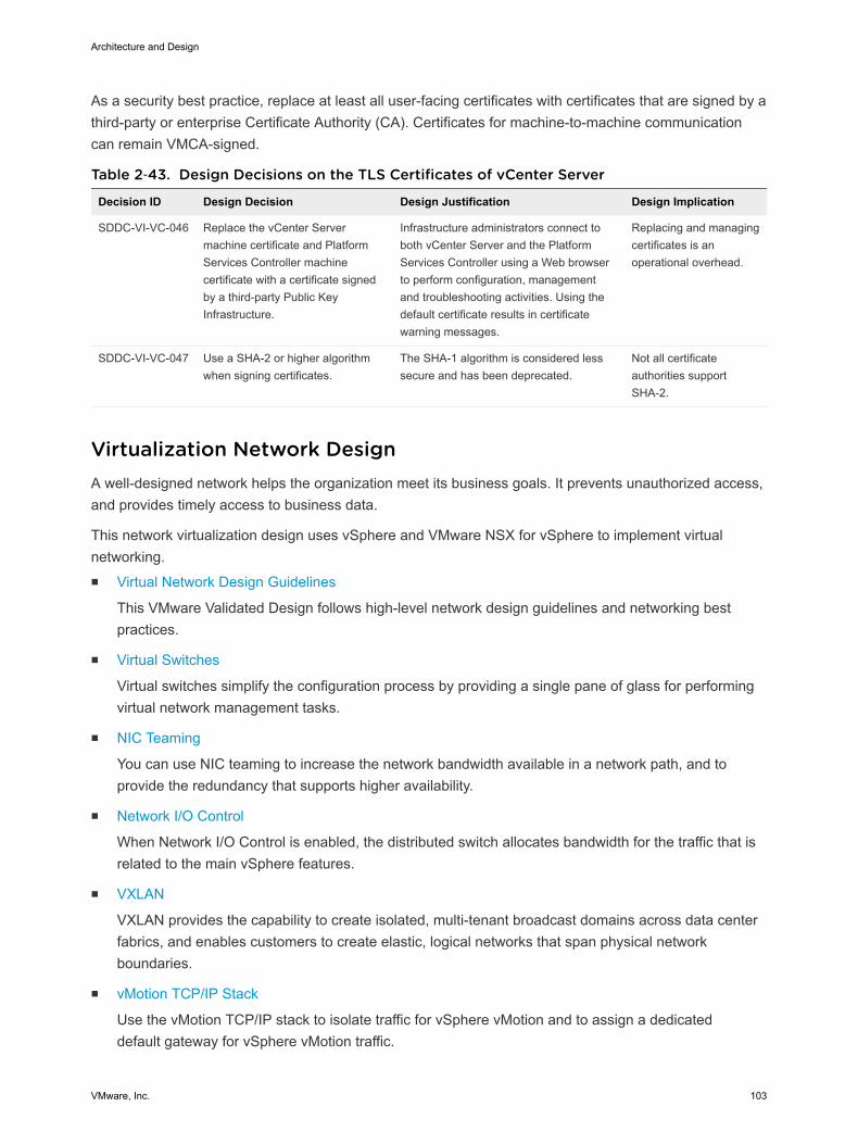
As a security best practice, replace at least all user-facing certificates with certificates that are signed by athird-party or enterprise Certificate Authority (CA). Certificates for machine-to-machine communicationcan remain VMCA-signed.
Table 2‑43. Design Decisions on the TLS Certificates of vCenter Server
Decision ID Design Decision Design Justification Design Implication
SDDC-VI-VC-046 Replace the vCenter Servermachine certificate and PlatformServices Controller machinecertificate with a certificate signedby a third-party Public KeyInfrastructure.
Infrastructure administrators connect toboth vCenter Server and the PlatformServices Controller using a Web browserto perform configuration, managementand troubleshooting activities. Using thedefault certificate results in certificatewarning messages.
Replacing and managingcertificates is anoperational overhead.
SDDC-VI-VC-047 Use a SHA-2 or higher algorithmwhen signing certificates.
The SHA-1 algorithm is considered lesssecure and has been deprecated.
Not all certificateauthorities supportSHA-2.
Virtualization Network Design A well-designed network helps the organization meet its business goals. It prevents unauthorized access,and provides timely access to business data.
This network virtualization design uses vSphere and VMware NSX for vSphere to implement virtualnetworking.n Virtual Network Design Guidelines
This VMware Validated Design follows high-level network design guidelines and networking bestpractices.
n Virtual Switches
Virtual switches simplify the configuration process by providing a single pane of glass for performingvirtual network management tasks.
n NIC Teaming
You can use NIC teaming to increase the network bandwidth available in a network path, and toprovide the redundancy that supports higher availability.
n Network I/O Control
When Network I/O Control is enabled, the distributed switch allocates bandwidth for the traffic that isrelated to the main vSphere features.
n VXLAN
VXLAN provides the capability to create isolated, multi-tenant broadcast domains across data centerfabrics, and enables customers to create elastic, logical networks that span physical networkboundaries.
n vMotion TCP/IP Stack
Use the vMotion TCP/IP stack to isolate traffic for vSphere vMotion and to assign a dedicateddefault gateway for vSphere vMotion traffic.
Architecture and Design
VMware, Inc. 103

Virtual Network Design Guidelines This VMware Validated Design follows high-level network design guidelines and networking bestpractices.
Design Goals
The high-level design goals apply regardless of your environment.
n Meet diverse needs. The network must meet the diverse needs of many different entities in anorganization. These entities include applications, services, storage, administrators, and users.
n Reduce costs. Reducing costs is one of the simpler goals to achieve in the vSphere infrastructure.Server consolidation alone reduces network costs by reducing the number of required network portsand NICs, but a more efficient network design is desirable. For example, configuring two 10-GbENICs with VLANs might be more cost effective than configuring a dozen 1-GbE NICs on separatephysical networks.
n Improve performance. You can achieve performance improvement and decrease the time that isrequired to perform maintenance by providing sufficient bandwidth, which reduces contention andlatency.
n Improve availability. A well-designed network improves availability, usually by providing networkredundancy.
n Support security. A well-designed network supports an acceptable level of security through controlledaccess and isolation, where required.
n Enhance infrastructure functionality. You can configure the network to support vSphere features suchas vSphere vMotion, vSphere High Availability, and vSphere Fault Tolerance.
Best Practices
Follow networking best practices throughout your environment.
n Separate network services from one another to achieve greater security and better performance.
n Use Network I/O Control and traffic shaping to guarantee bandwidth to critical virtual machines.During network contention, these critical virtual machines will receive a higher percentage of thebandwidth.
n Separate network services on a single vSphere Distributed Switch by attaching them to port groupswith different VLAN IDs.
n Keep vSphere vMotion traffic on a separate network.
When a migration using vSphere vMotion occurs, the contents of the memory of the guest operatingsystem is transmitted over the network. You can place vSphere vMotion on a separate network byusing a dedicated vSphere vMotion VLAN.
n When using pass-through devices with Linux kernel version 2.6.20 or an earlier guest OS, avoid MSIand MSI-X modes. These modes have significant performance impact.
Architecture and Design
VMware, Inc. 104
n For best performance, use VMXNET3 virtual machine NICs.
n Ensure that physical network adapters that are connected to the same vSphere Standard Switch orvSphere Distributed Switch, are also connected to the same physical network.
Network Segmentation and VLANs
Separating different types of traffic is required to reduce contention and latency, and for access security.
High latency on any network can negatively affect performance. Some components are more sensitive tohigh latency than others. For example, reducing latency is important on the IP storage and the vSphereFault Tolerance logging network because latency on these networks can negatively affect theperformance of multiple virtual machines.
According to the application or service, high latency on specific virtual machine networks can alsonegatively affect performance. Use information gathered from the current state analysis and frominterviews with key stakeholder and SMEs to determine which workloads and networks are especiallysensitive to high latency.
Virtual Networks
Determine the number of networks or VLANs that are required depending on the type of traffic.
n vSphere operational traffic.
n Management
n vMotion
n vSAN
n NFS Storage
n vSphere Replication
n VXLAN
n Traffic that supports the services and applications in the organization.
Virtual Switches Virtual switches simplify the configuration process by providing a single pane of glass for performingvirtual network management tasks.
Architecture and Design
VMware, Inc. 105
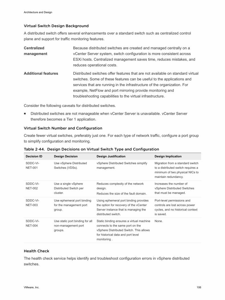
Virtual Switch Design Background
A distributed switch offers several enhancements over a standard switch such as centralized controlplane and support for traffic monitoring features.
Centralizedmanagement
Because distributed switches are created and managed centrally on avCenter Server system, switch configuration is more consistent acrossESXi hosts. Centralized management saves time, reduces mistakes, andreduces operational costs.
Additional features Distributed switches offer features that are not available on standard virtualswitches. Some of these features can be useful to the applications andservices that are running in the infrastructure of the organization. Forexample, NetFlow and port mirroring provide monitoring andtroubleshooting capabilities to the virtual infrastructure.
Consider the following caveats for distributed switches.
n Distributed switches are not manageable when vCenter Server is unavailable. vCenter Servertherefore becomes a Tier 1 application.
Virtual Switch Number and Configuration
Create fewer virtual switches, preferably just one. For each type of network traffic, configure a port groupto simplify configuration and monitoring.
Table 2‑44. Design Decisions on Virtual Switch Type and Configuration
Decision ID Design Decision Design Justification Design Implication
SDDC-VI-NET-001
Use vSphere DistributedSwitches (VDSs).
vSphere Distributed Switches simplifymanagement.
Migration from a standard switchto a distributed switch requires aminimum of two physical NICs tomaintain redundancy.
SDDC-VI-NET-002
Use a single vSphereDistributed Switch percluster.
Reduces complexity of the networkdesign.
Reduces the size of the fault domain.
Increases the number ofvSphere Distributed Switchesthat must be managed.
SDDC-VI-NET-003
Use ephemeral port bindingfor the management portgroup.
Using ephemeral port binding providesthe option for recovery of the vCenterServer instance that is managing thedistributed switch.
Port-level permissions andcontrols are lost across powercycles, and no historical contextis saved.
SDDC-VI-NET-004
Use static port binding for allnon-management portgroups.
Static binding ensures a virtual machineconnects to the same port on thevSphere Distributed Switch. This allowsfor historical data and port levelmonitoring .
None.
Health Check
The health check service helps identify and troubleshoot configuration errors in vSphere distributedswitches.
Architecture and Design
VMware, Inc. 106
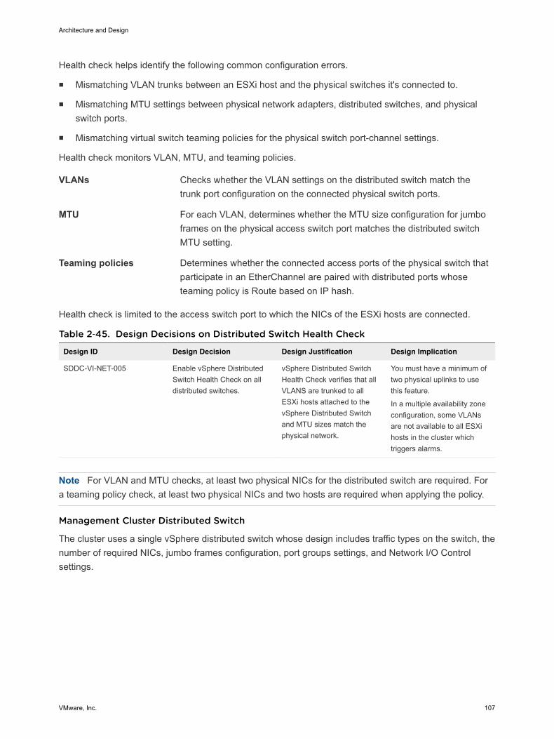
Health check helps identify the following common configuration errors.
n Mismatching VLAN trunks between an ESXi host and the physical switches it's connected to.
n Mismatching MTU settings between physical network adapters, distributed switches, and physicalswitch ports.
n Mismatching virtual switch teaming policies for the physical switch port-channel settings.
Health check monitors VLAN, MTU, and teaming policies.
VLANs Checks whether the VLAN settings on the distributed switch match thetrunk port configuration on the connected physical switch ports.
MTU For each VLAN, determines whether the MTU size configuration for jumboframes on the physical access switch port matches the distributed switchMTU setting.
Teaming policies Determines whether the connected access ports of the physical switch thatparticipate in an EtherChannel are paired with distributed ports whoseteaming policy is Route based on IP hash.
Health check is limited to the access switch port to which the NICs of the ESXi hosts are connected.
Table 2‑45. Design Decisions on Distributed Switch Health Check
Design ID Design Decision Design Justification Design Implication
SDDC-VI-NET-005 Enable vSphere DistributedSwitch Health Check on alldistributed switches.
vSphere Distributed SwitchHealth Check verifies that allVLANS are trunked to allESXi hosts attached to thevSphere Distributed Switchand MTU sizes match thephysical network.
You must have a minimum oftwo physical uplinks to usethis feature.
In a multiple availability zoneconfiguration, some VLANsare not available to all ESXihosts in the cluster whichtriggers alarms.
Note For VLAN and MTU checks, at least two physical NICs for the distributed switch are required. Fora teaming policy check, at least two physical NICs and two hosts are required when applying the policy.
Management Cluster Distributed Switch
The cluster uses a single vSphere distributed switch whose design includes traffic types on the switch, thenumber of required NICs, jumbo frames configuration, port groups settings, and Network I/O Controlsettings.
Architecture and Design
VMware, Inc. 107
Table 2‑46. Virtual Switch for the Management Cluster
vSphere DistributedSwitch Name Function
Network I/OControl
Number ofPhysical NIC Ports MTU
sfo01-m01-vds01 n ESXi Managementn Network IP Storage (NFS)n vSANn vSphere vMotionn VXLAN Tunnel Endpoint (VTEP)n vSphere Replication/vSphere Replication
NFCn Uplinks (2) for ECMP
Enabled 2 9000
Table 2‑47. Configuration Settings of the Management Port Group
Parameter Setting
Failover detection Link status only
Notify switches Enabled
Failback Yes
Failover order Active uplinks: Uplink1, Uplink2
Figure 2‑11. Network Switch Design for Management ESXi Hosts
Architecture and Design
VMware, Inc. 108
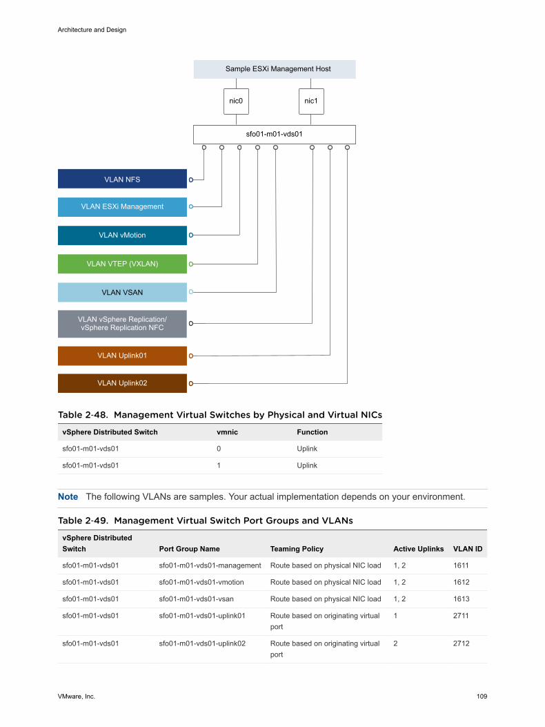
nic0 nic1
VLAN VSAN
VLAN ESXi Management
VLAN vMotion
VLAN VTEP (VXLAN)
Sample ESXi Management Host
VLAN vSphere Replication/vSphere Replication NFC
sfo01-m01-vds01
VLAN NFS
VLAN Uplink01
VLAN Uplink02
Table 2‑48. Management Virtual Switches by Physical and Virtual NICs
vSphere Distributed Switch vmnic Function
sfo01-m01-vds01 0 Uplink
sfo01-m01-vds01 1 Uplink
Note The following VLANs are samples. Your actual implementation depends on your environment.
Table 2‑49. Management Virtual Switch Port Groups and VLANs
vSphere DistributedSwitch Port Group Name Teaming Policy Active Uplinks VLAN ID
sfo01-m01-vds01 sfo01-m01-vds01-management Route based on physical NIC load 1, 2 1611
sfo01-m01-vds01 sfo01-m01-vds01-vmotion Route based on physical NIC load 1, 2 1612
sfo01-m01-vds01 sfo01-m01-vds01-vsan Route based on physical NIC load 1, 2 1613
sfo01-m01-vds01 sfo01-m01-vds01-uplink01 Route based on originating virtualport
1 2711
sfo01-m01-vds01 sfo01-m01-vds01-uplink02 Route based on originating virtualport
2 2712
Architecture and Design
VMware, Inc. 109
Table 2‑49. Management Virtual Switch Port Groups and VLANs (Continued)
vSphere DistributedSwitch Port Group Name Teaming Policy Active Uplinks VLAN ID
sfo01-m01-vds01 sfo01-m01-vds01-nfs Route based on physical NIC load 1, 2 1615
sfo01-m01-vds01 sfo01-m01-vds01-replication Route based on physical NIC load 1, 2 1616
sfo01-m01-vds01 sfo02-m01-vds01-management Route based on physical NIC load 1, 2 1621
sfo01-m01-vds01 sfo02-m01-vds01-vmotion Route based on physical NIC load 1, 2 1622
sfo01-m01-vds01 sfo02-m01-vds01-vsan Route based on physical NIC load 1, 2 1623
sfo01-m01-vds01 sfo02-m01-vds01-uplink01 Route based on originating port 1 2721
sfo01-m01-vds01 sfo02-m01-vds01-uplink02 Route based on originating port 2 2722
sfo01-m01-vds01 sfo02-m01-vds01-nfs Route based on physical NIC load 1, 2 1625
sfo01-m01-vds01 sfo02-m01-vds01-replication Route based on physical NIC load 1, 2 1626
sfo01-m01-vds01 Auto Generated (NSX VTEP) Route based on SRC-ID 1, 2 1614
Table 2‑50. Management VMkernel Adapters
vSphere DistributedSwitch Network Label Connected Port Group Enabled Services MTU
sfo01-m01-vds01 Management sfo01-m01-vds01-management Management Traffic 1500 (Default)
sfo01-m01-vds01 vMotion sfo01-m01-vds01-vmotion vMotion Traffic 9000
sfo01-m01-vds01 vSAN sfo01-m01-vds01-vsan vSAN 9000
sfo01-m01-vds01 NFS sfo01-m01-vds01-nfs - 9000
sfo01-m01-vds01 Replication sfo01-m01-vds01-replication vSphere Replication traffic
vSphere Replication NFCtraffic
9000
sfo01-m01-vds01 Management sfo02-m01-vds01-management Management Traffic 1500 (Default)
sfo01-m01-vds01 vMotion sfo02-m01-vds01-vmotion vMotion Traffic 9000
sfo01-m01-vds01 vSAN sfo02-m01-vds01-vsan vSAN 9000
sfo01-m01-vds01 NFS sfo02-m01-vds01-nfs - 9000
sfo01-m01-vds01 Replication sfo02-m01-vds01-replication vSphere Replication trafficvSphere Replication NFCtraffic
9000
sfo01-m01-vds01 VTEP Auto-generated (NSX VTEP) - 9000
For more information on the physical network design specifications, see Physical Networking Design.
Shared Edge and Compute Cluster Distributed Switches
The shared edge and compute cluster uses a single vSphere distributed switch whose design includestraffic types on the switch, number of required NICs, jumbo frames configuration, port groups settings,and Network I/O Control settings.
Architecture and Design
VMware, Inc. 110
Table 2‑51. Virtual Switch for the Shared Edge and Compute Cluster
vSphere Distributed SwitchName Function Network I/O Control
Number of Physical NICPorts MTU
sfo01-w01-vds01 n ESXi Managementn Network IP Storage (NFS)n vSphere vMotionn VXLAN Tunnel Endpoint (VTEP)n Uplinks (2) to enable ECMPn vSAN
Enabled 2 9000
Table 2‑52. Configuration Settings of the Shared Edge and Compute Port Groups
Parameter Setting
Failover detection Link status only
Notify switches Enabled
Failback Yes
Failover order Active uplinks: Uplink1, Uplink2
Network Switch Design for Shared Edge and Compute ESXi Hosts
When you design the switch configuration on the ESXi hosts, consider the physical NIC layout andphysical network attributes.
Architecture and Design
VMware, Inc. 111
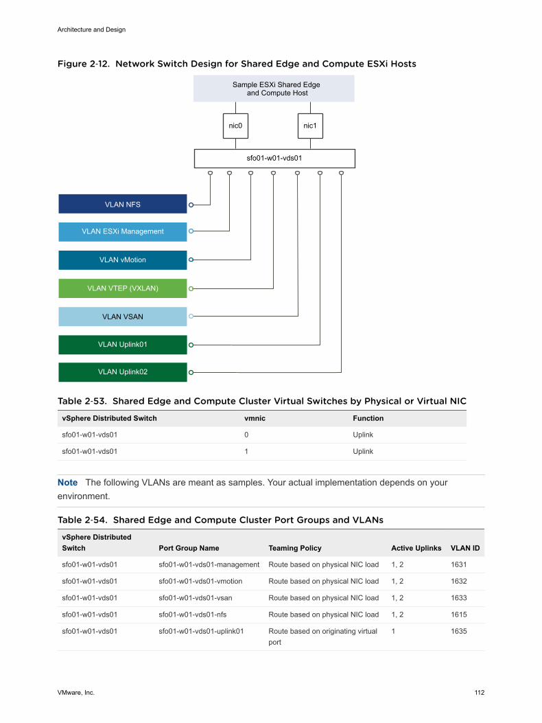
Figure 2‑12. Network Switch Design for Shared Edge and Compute ESXi Hosts
nic0 nic1
VLAN VSAN
VLAN ESXi Management
VLAN vMotion
VLAN VTEP (VXLAN)
Sample ESXi Shared Edge and Compute Host
sfo01-w01-vds01
VLAN NFS
VLAN Uplink01
VLAN Uplink02
Table 2‑53. Shared Edge and Compute Cluster Virtual Switches by Physical or Virtual NIC
vSphere Distributed Switch vmnic Function
sfo01-w01-vds01 0 Uplink
sfo01-w01-vds01 1 Uplink
Note The following VLANs are meant as samples. Your actual implementation depends on yourenvironment.
Table 2‑54. Shared Edge and Compute Cluster Port Groups and VLANs
vSphere DistributedSwitch Port Group Name Teaming Policy Active Uplinks VLAN ID
sfo01-w01-vds01 sfo01-w01-vds01-management Route based on physical NIC load 1, 2 1631
sfo01-w01-vds01 sfo01-w01-vds01-vmotion Route based on physical NIC load 1, 2 1632
sfo01-w01-vds01 sfo01-w01-vds01-vsan Route based on physical NIC load 1, 2 1633
sfo01-w01-vds01 sfo01-w01-vds01-nfs Route based on physical NIC load 1, 2 1615
sfo01-w01-vds01 sfo01-w01-vds01-uplink01 Route based on originating virtualport
1 1635
Architecture and Design
VMware, Inc. 112
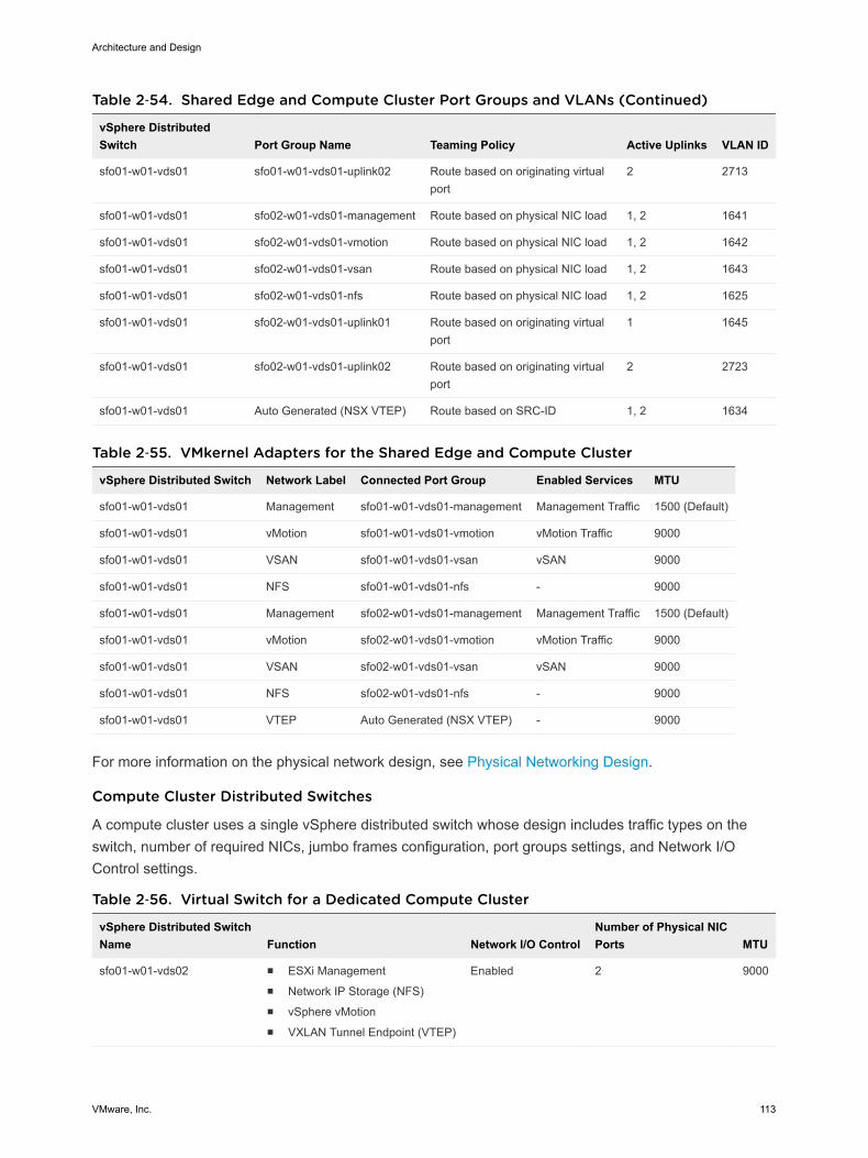
Table 2‑54. Shared Edge and Compute Cluster Port Groups and VLANs (Continued)
vSphere DistributedSwitch Port Group Name Teaming Policy Active Uplinks VLAN ID
sfo01-w01-vds01 sfo01-w01-vds01-uplink02 Route based on originating virtualport
2 2713
sfo01-w01-vds01 sfo02-w01-vds01-management Route based on physical NIC load 1, 2 1641
sfo01-w01-vds01 sfo02-w01-vds01-vmotion Route based on physical NIC load 1, 2 1642
sfo01-w01-vds01 sfo02-w01-vds01-vsan Route based on physical NIC load 1, 2 1643
sfo01-w01-vds01 sfo02-w01-vds01-nfs Route based on physical NIC load 1, 2 1625
sfo01-w01-vds01 sfo02-w01-vds01-uplink01 Route based on originating virtualport
1 1645
sfo01-w01-vds01 sfo02-w01-vds01-uplink02 Route based on originating virtualport
2 2723
sfo01-w01-vds01 Auto Generated (NSX VTEP) Route based on SRC-ID 1, 2 1634
Table 2‑55. VMkernel Adapters for the Shared Edge and Compute Cluster
vSphere Distributed Switch Network Label Connected Port Group Enabled Services MTU
sfo01-w01-vds01 Management sfo01-w01-vds01-management Management Traffic 1500 (Default)
sfo01-w01-vds01 vMotion sfo01-w01-vds01-vmotion vMotion Traffic 9000
sfo01-w01-vds01 VSAN sfo01-w01-vds01-vsan vSAN 9000
sfo01-w01-vds01 NFS sfo01-w01-vds01-nfs - 9000
sfo01-w01-vds01 Management sfo02-w01-vds01-management Management Traffic 1500 (Default)
sfo01-w01-vds01 vMotion sfo02-w01-vds01-vmotion vMotion Traffic 9000
sfo01-w01-vds01 VSAN sfo02-w01-vds01-vsan vSAN 9000
sfo01-w01-vds01 NFS sfo02-w01-vds01-nfs - 9000
sfo01-w01-vds01 VTEP Auto Generated (NSX VTEP) - 9000
For more information on the physical network design, see Physical Networking Design.
Compute Cluster Distributed Switches
А compute cluster uses a single vSphere distributed switch whose design includes traffic types on theswitch, number of required NICs, jumbo frames configuration, port groups settings, and Network I/OControl settings.
Table 2‑56. Virtual Switch for a Dedicated Compute Cluster
vSphere Distributed SwitchName Function Network I/O Control
Number of Physical NICPorts MTU
sfo01-w01-vds02 n ESXi Managementn Network IP Storage (NFS)n vSphere vMotionn VXLAN Tunnel Endpoint (VTEP)
Enabled 2 9000
Architecture and Design
VMware, Inc. 113
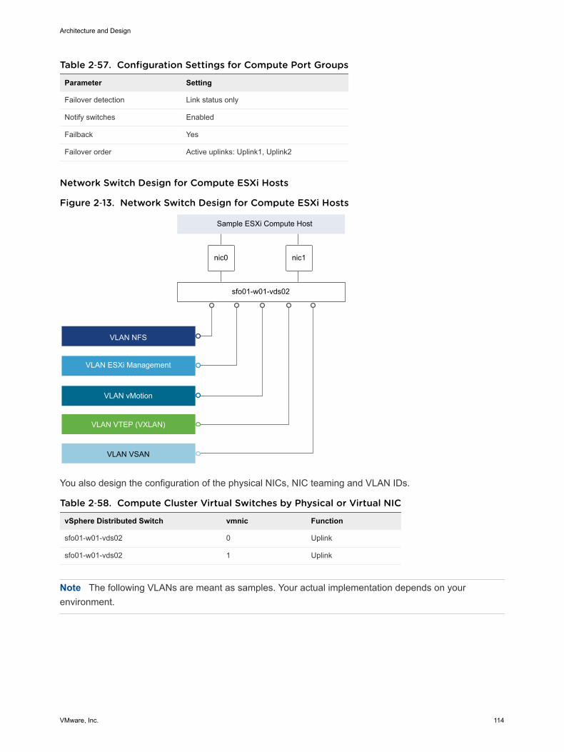
Table 2‑57. Configuration Settings for Compute Port Groups
Parameter Setting
Failover detection Link status only
Notify switches Enabled
Failback Yes
Failover order Active uplinks: Uplink1, Uplink2
Network Switch Design for Compute ESXi Hosts
Figure 2‑13. Network Switch Design for Compute ESXi Hosts
nic0 nic1
VLAN VSAN
VLAN ESXi Management
VLAN vMotion
VLAN VTEP (VXLAN)
Sample ESXi Compute Host
VLAN NFS
sfo01-w01-vds02
You also design the configuration of the physical NICs, NIC teaming and VLAN IDs.
Table 2‑58. Compute Cluster Virtual Switches by Physical or Virtual NIC
vSphere Distributed Switch vmnic Function
sfo01-w01-vds02 0 Uplink
sfo01-w01-vds02 1 Uplink
Note The following VLANs are meant as samples. Your actual implementation depends on yourenvironment.
Architecture and Design
VMware, Inc. 114
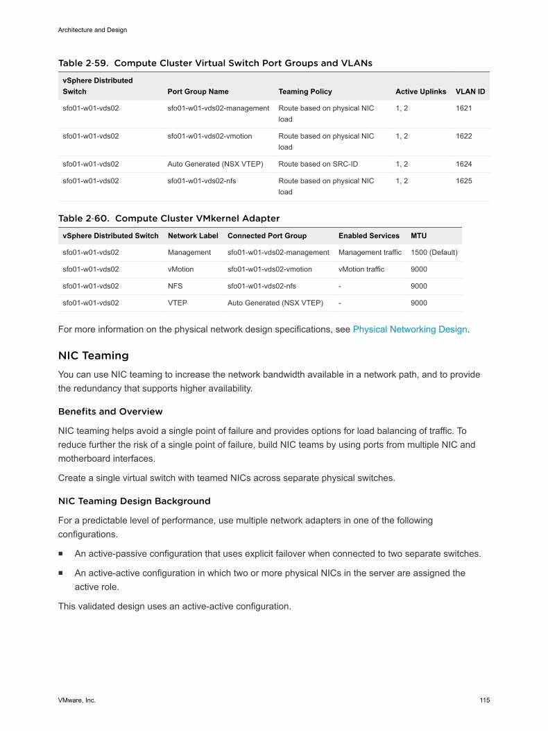
Table 2‑59. Compute Cluster Virtual Switch Port Groups and VLANs
vSphere DistributedSwitch Port Group Name Teaming Policy Active Uplinks VLAN ID
sfo01-w01-vds02 sfo01-w01-vds02-management Route based on physical NICload
1, 2 1621
sfo01-w01-vds02 sfo01-w01-vds02-vmotion Route based on physical NICload
1, 2 1622
sfo01-w01-vds02 Auto Generated (NSX VTEP) Route based on SRC-ID 1, 2 1624
sfo01-w01-vds02 sfo01-w01-vds02-nfs Route based on physical NICload
1, 2 1625
Table 2‑60. Compute Cluster VMkernel Adapter
vSphere Distributed Switch Network Label Connected Port Group Enabled Services MTU
sfo01-w01-vds02 Management sfo01-w01-vds02-management Management traffic 1500 (Default)
sfo01-w01-vds02 vMotion sfo01-w01-vds02-vmotion vMotion traffic 9000
sfo01-w01-vds02 NFS sfo01-w01-vds02-nfs - 9000
sfo01-w01-vds02 VTEP Auto Generated (NSX VTEP) - 9000
For more information on the physical network design specifications, see Physical Networking Design.
NIC Teaming You can use NIC teaming to increase the network bandwidth available in a network path, and to providethe redundancy that supports higher availability.
Benefits and Overview
NIC teaming helps avoid a single point of failure and provides options for load balancing of traffic. Toreduce further the risk of a single point of failure, build NIC teams by using ports from multiple NIC andmotherboard interfaces.
Create a single virtual switch with teamed NICs across separate physical switches.
NIC Teaming Design Background
For a predictable level of performance, use multiple network adapters in one of the followingconfigurations.
n An active-passive configuration that uses explicit failover when connected to two separate switches.
n An active-active configuration in which two or more physical NICs in the server are assigned theactive role.
This validated design uses an active-active configuration.
Architecture and Design
VMware, Inc. 115
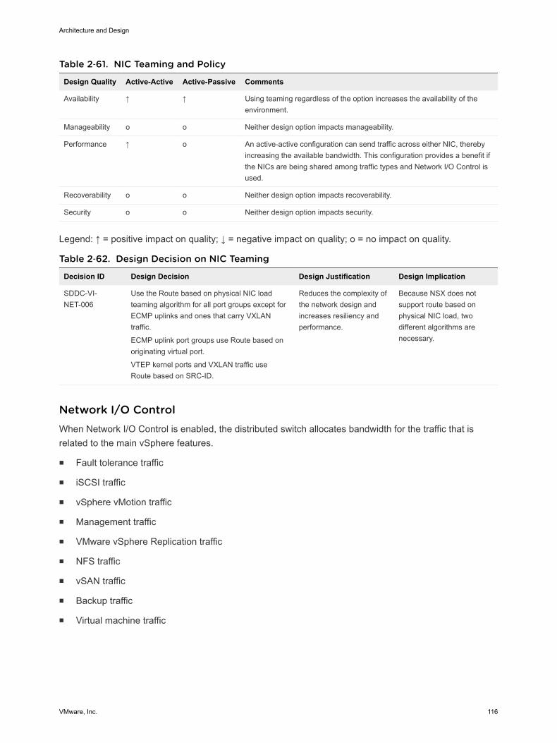
Table 2‑61. NIC Teaming and Policy
Design Quality Active-Active Active-Passive Comments
Availability ↑ ↑ Using teaming regardless of the option increases the availability of theenvironment.
Manageability o o Neither design option impacts manageability.
Performance ↑ o An active-active configuration can send traffic across either NIC, therebyincreasing the available bandwidth. This configuration provides a benefit ifthe NICs are being shared among traffic types and Network I/O Control isused.
Recoverability o o Neither design option impacts recoverability.
Security o o Neither design option impacts security.
Legend: ↑ = positive impact on quality; ↓ = negative impact on quality; o = no impact on quality.
Table 2‑62. Design Decision on NIC Teaming
Decision ID Design Decision Design Justification Design Implication
SDDC-VI-NET-006
Use the Route based on physical NIC loadteaming algorithm for all port groups except forECMP uplinks and ones that carry VXLANtraffic.
ECMP uplink port groups use Route based onoriginating virtual port.
VTEP kernel ports and VXLAN traffic useRoute based on SRC-ID.
Reduces the complexity ofthe network design andincreases resiliency andperformance.
Because NSX does notsupport route based onphysical NIC load, twodifferent algorithms arenecessary.
Network I/O Control When Network I/O Control is enabled, the distributed switch allocates bandwidth for the traffic that isrelated to the main vSphere features.
n Fault tolerance traffic
n iSCSI traffic
n vSphere vMotion traffic
n Management traffic
n VMware vSphere Replication traffic
n NFS traffic
n vSAN traffic
n Backup traffic
n Virtual machine traffic
Architecture and Design
VMware, Inc. 116

Network I/O Control Heuristics
The following heuristics can help with design decisions for Network I/O Control.
Shares and Limits When you use bandwidth allocation, consider using shares instead of limits.Limits impose hard limits on the amount of bandwidth used by a traffic floweven when network bandwidth is available.
Limits on NetworkResource Pools
Consider imposing limits on a given network resource pool. For example, ifyou put a limit on vSphere vMotion traffic, you can benefit in situationswhere multiple vSphere vMotion data transfers, initiated on different ESXihosts at the same time, result in oversubscription at the physical networklevel. By limiting the available bandwidth for vSphere vMotion at the ESXihost level, you can prevent performance degradation for other traffic.
Teaming Policy When you use Network I/O Control, use Route based on physical NIC loadteaming as a distributed switch teaming policy to maximize the networkingcapacity utilization. With load-based teaming, traffic might move amonguplinks, and reordering of packets at the receiver can result occasionally.
Traffic Shaping Use distributed port groups to apply configuration policies to different traffictypes. Traffic shaping can help in situations where multiple vSpherevMotion migrations initiated on different ESXi hosts converge on the samedestination ESXi host. The actual limit and reservation also depend on thetraffic shaping policy for the distributed port group where the adapter isconnected to.
How Network I/O Control Works
Network I/O Control enforces the share value specified for the different traffic types when a networkcontention occurs. Network I/O Control applies the share values set to each traffic type. As a result, lessimportant traffic, as defined by the share percentage, is throttled, granting access to more networkresources to more important traffic types.
Network I/O Control also supports reservation of bandwidth for system traffic based on the capacity of thephysical adapters on an ESXi host, and enables fine-grained resource control at the virtual machinenetwork adapter level. Resource control is similar to the model for CPU and memory reservations invSphere DRS.
Network I/O Control Design Decisions
Based on the heuristics, this design has the following decisions.
Architecture and Design
VMware, Inc. 117
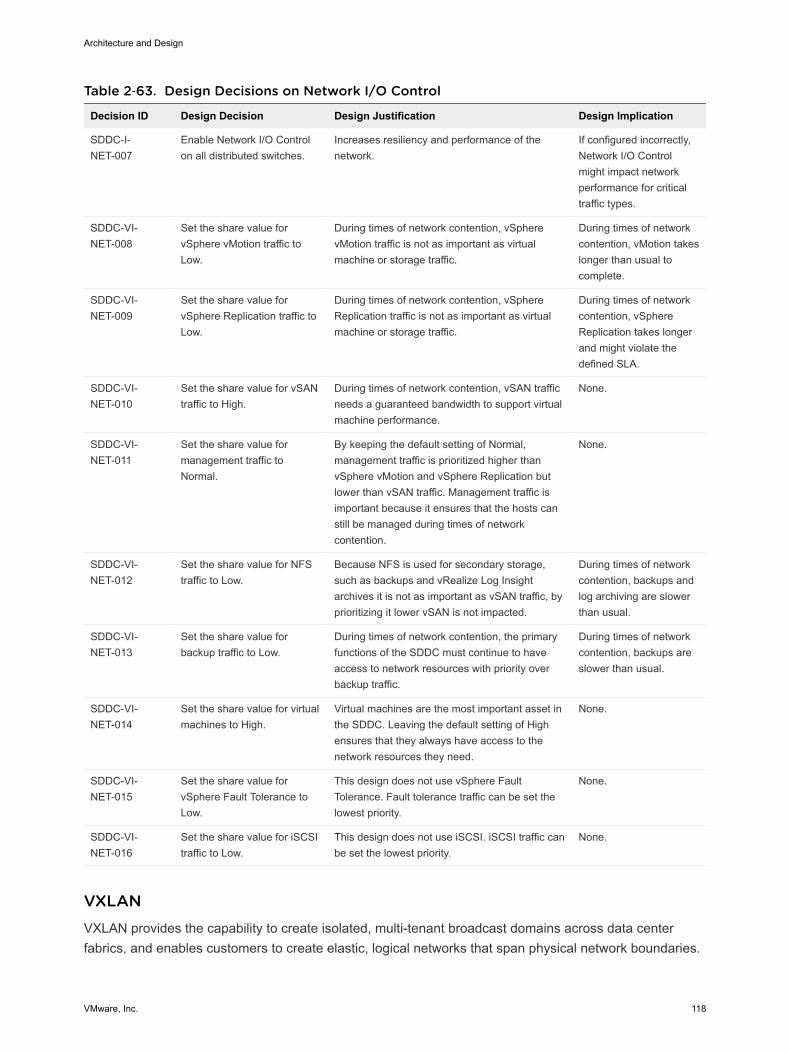
Table 2‑63. Design Decisions on Network I/O Control
Decision ID Design Decision Design Justification Design Implication
SDDC-I-NET-007
Enable Network I/O Controlon all distributed switches.
Increases resiliency and performance of thenetwork.
If configured incorrectly,Network I/O Controlmight impact networkperformance for criticaltraffic types.
SDDC-VI-NET-008
Set the share value forvSphere vMotion traffic toLow.
During times of network contention, vSpherevMotion traffic is not as important as virtualmachine or storage traffic.
During times of networkcontention, vMotion takeslonger than usual tocomplete.
SDDC-VI-NET-009
Set the share value forvSphere Replication traffic toLow.
During times of network contention, vSphereReplication traffic is not as important as virtualmachine or storage traffic.
During times of networkcontention, vSphereReplication takes longerand might violate thedefined SLA.
SDDC-VI-NET-010
Set the share value for vSANtraffic to High.
During times of network contention, vSAN trafficneeds a guaranteed bandwidth to support virtualmachine performance.
None.
SDDC-VI-NET-011
Set the share value formanagement traffic toNormal.
By keeping the default setting of Normal,management traffic is prioritized higher thanvSphere vMotion and vSphere Replication butlower than vSAN traffic. Management traffic isimportant because it ensures that the hosts canstill be managed during times of networkcontention.
None.
SDDC-VI-NET-012
Set the share value for NFStraffic to Low.
Because NFS is used for secondary storage,such as backups and vRealize Log Insightarchives it is not as important as vSAN traffic, byprioritizing it lower vSAN is not impacted.
During times of networkcontention, backups andlog archiving are slowerthan usual.
SDDC-VI-NET-013
Set the share value forbackup traffic to Low.
During times of network contention, the primaryfunctions of the SDDC must continue to haveaccess to network resources with priority overbackup traffic.
During times of networkcontention, backups areslower than usual.
SDDC-VI-NET-014
Set the share value for virtualmachines to High.
Virtual machines are the most important asset inthe SDDC. Leaving the default setting of Highensures that they always have access to thenetwork resources they need.
None.
SDDC-VI-NET-015
Set the share value forvSphere Fault Tolerance toLow.
This design does not use vSphere FaultTolerance. Fault tolerance traffic can be set thelowest priority.
None.
SDDC-VI-NET-016
Set the share value for iSCSItraffic to Low.
This design does not use iSCSI. iSCSI traffic canbe set the lowest priority.
None.
VXLAN VXLAN provides the capability to create isolated, multi-tenant broadcast domains across data centerfabrics, and enables customers to create elastic, logical networks that span physical network boundaries.
Architecture and Design
VMware, Inc. 118
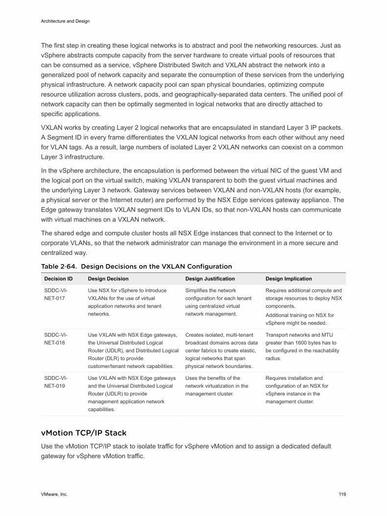
The first step in creating these logical networks is to abstract and pool the networking resources. Just asvSphere abstracts compute capacity from the server hardware to create virtual pools of resources thatcan be consumed as a service, vSphere Distributed Switch and VXLAN abstract the network into ageneralized pool of network capacity and separate the consumption of these services from the underlyingphysical infrastructure. A network capacity pool can span physical boundaries, optimizing computeresource utilization across clusters, pods, and geographically-separated data centers. The unified pool ofnetwork capacity can then be optimally segmented in logical networks that are directly attached tospecific applications.
VXLAN works by creating Layer 2 logical networks that are encapsulated in standard Layer 3 IP packets.A Segment ID in every frame differentiates the VXLAN logical networks from each other without any needfor VLAN tags. As a result, large numbers of isolated Layer 2 VXLAN networks can coexist on a commonLayer 3 infrastructure.
In the vSphere architecture, the encapsulation is performed between the virtual NIC of the guest VM andthe logical port on the virtual switch, making VXLAN transparent to both the guest virtual machines andthe underlying Layer 3 network. Gateway services between VXLAN and non-VXLAN hosts (for example,a physical server or the Internet router) are performed by the NSX Edge services gateway appliance. TheEdge gateway translates VXLAN segment IDs to VLAN IDs, so that non-VXLAN hosts can communicatewith virtual machines on a VXLAN network.
The shared edge and compute cluster hosts all NSX Edge instances that connect to the Internet or tocorporate VLANs, so that the network administrator can manage the environment in a more secure andcentralized way.
Table 2‑64. Design Decisions on the VXLAN Configuration
Decision ID Design Decision Design Justification Design Implication
SDDC-VI-NET-017
Use NSX for vSphere to introduceVXLANs for the use of virtualapplication networks and tenantnetworks.
Simplifies the networkconfiguration for each tenantusing centralized virtualnetwork management.
Requires additional compute andstorage resources to deploy NSXcomponents.
Additional training on NSX forvSphere might be needed.
SDDC-VI-NET-018
Use VXLAN with NSX Edge gateways,the Universal Distributed LogicalRouter (UDLR), and Distributed LogicalRouter (DLR) to providecustomer/tenant network capabilities.
Creates isolated, multi-tenantbroadcast domains across datacenter fabrics to create elastic,logical networks that spanphysical network boundaries.
Transport networks and MTUgreater than 1600 bytes has tobe configured in the reachabilityradius.
SDDC-VI-NET-019
Use VXLAN with NSX Edge gatewaysand the Universal Distributed LogicalRouter (UDLR) to providemanagement application networkcapabilities.
Uses the benefits of thenetwork virtualization in themanagement cluster.
Requires installation andconfiguration of an NSX forvSphere instance in themanagement cluster.
vMotion TCP/IP Stack Use the vMotion TCP/IP stack to isolate traffic for vSphere vMotion and to assign a dedicated defaultgateway for vSphere vMotion traffic.
Architecture and Design
VMware, Inc. 119
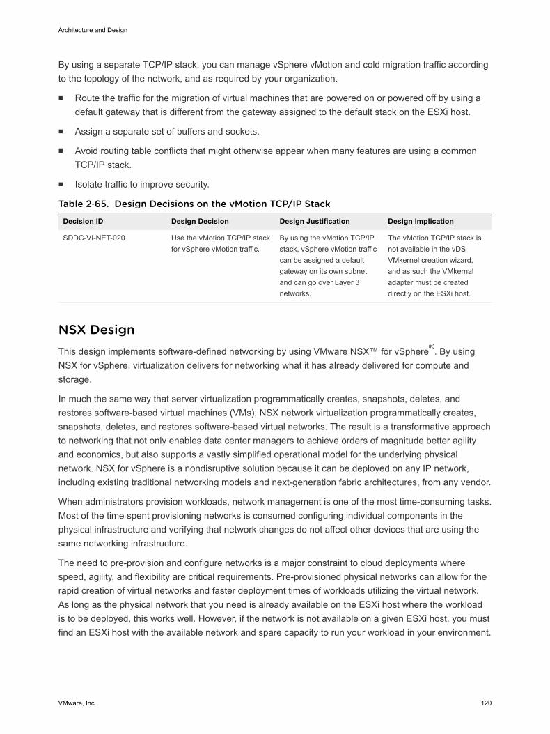
By using a separate TCP/IP stack, you can manage vSphere vMotion and cold migration traffic accordingto the topology of the network, and as required by your organization.
n Route the traffic for the migration of virtual machines that are powered on or powered off by using adefault gateway that is different from the gateway assigned to the default stack on the ESXi host.
n Assign a separate set of buffers and sockets.
n Avoid routing table conflicts that might otherwise appear when many features are using a commonTCP/IP stack.
n Isolate traffic to improve security.
Table 2‑65. Design Decisions on the vMotion TCP/IP Stack
Decision ID Design Decision Design Justification Design Implication
SDDC-VI-NET-020 Use the vMotion TCP/IP stackfor vSphere vMotion traffic.
By using the vMotion TCP/IPstack, vSphere vMotion trafficcan be assigned a defaultgateway on its own subnetand can go over Layer 3networks.
The vMotion TCP/IP stack isnot available in the vDSVMkernel creation wizard,and as such the VMkernaladapter must be createddirectly on the ESXi host.
NSX Design This design implements software-defined networking by using VMware NSX™ for vSphere®. By usingNSX for vSphere, virtualization delivers for networking what it has already delivered for compute andstorage.
In much the same way that server virtualization programmatically creates, snapshots, deletes, andrestores software-based virtual machines (VMs), NSX network virtualization programmatically creates,snapshots, deletes, and restores software-based virtual networks. The result is a transformative approachto networking that not only enables data center managers to achieve orders of magnitude better agilityand economics, but also supports a vastly simplified operational model for the underlying physicalnetwork. NSX for vSphere is a nondisruptive solution because it can be deployed on any IP network,including existing traditional networking models and next-generation fabric architectures, from any vendor.
When administrators provision workloads, network management is one of the most time-consuming tasks.Most of the time spent provisioning networks is consumed configuring individual components in thephysical infrastructure and verifying that network changes do not affect other devices that are using thesame networking infrastructure.
The need to pre-provision and configure networks is a major constraint to cloud deployments wherespeed, agility, and flexibility are critical requirements. Pre-provisioned physical networks can allow for therapid creation of virtual networks and faster deployment times of workloads utilizing the virtual network.As long as the physical network that you need is already available on the ESXi host where the workloadis to be deployed, this works well. However, if the network is not available on a given ESXi host, you mustfind an ESXi host with the available network and spare capacity to run your workload in your environment.
Architecture and Design
VMware, Inc. 120

To get around this bottleneck, you decouple virtual networks from their physical counterparts. Decoupling,in turn, requires that you can programmatically recreate all physical networking attributes that arerequired by workloads in the virtualized environment. Because network virtualization supports the creationof virtual networks without modification of the physical network infrastructure, it allows more rapid networkprovisioning.
NSX for vSphere Design NSX Manager and vCenter Server have a one-to-one relationship. Per region, this design uses twovCenter Server instances and two NSX instances connected to them.
Table 2‑66. Design Decisions on the Instances of NSX for vSphere
DecisionID Design Decision Design Justification
DesignImplications
SDDC-VI-SDN-001
Use two separate NSX instancesper region. One instance is tied tothe Management vCenter Server,and the other instance is tied to theCompute vCenter Server.
Software-defined networking (SDN) capabilities offeredby NSX, such as load balancing and firewalls, arecrucial for the compute/edge layer to support the cloudmanagement platform operations, and also for themanagement applications in the management stackthat need these capabilities.
You must installand perform initialconfiguration ofmultiple NSXinstancesseparately.
SDDC-VI-SDN-002
Pair NSX Manager instances in aprimary-secondary relationshipacross regions for bothmanagement and computeworkloads.
NSX can extend the logical boundaries of thenetworking and security services across regions. As aresult, workloads can be live-migrated and failed overbetween regions without reconfiguring the network andsecurity constructs.
You must considerthat you can pairup to eight NSXManagerinstances.
Architecture and Design
VMware, Inc. 121
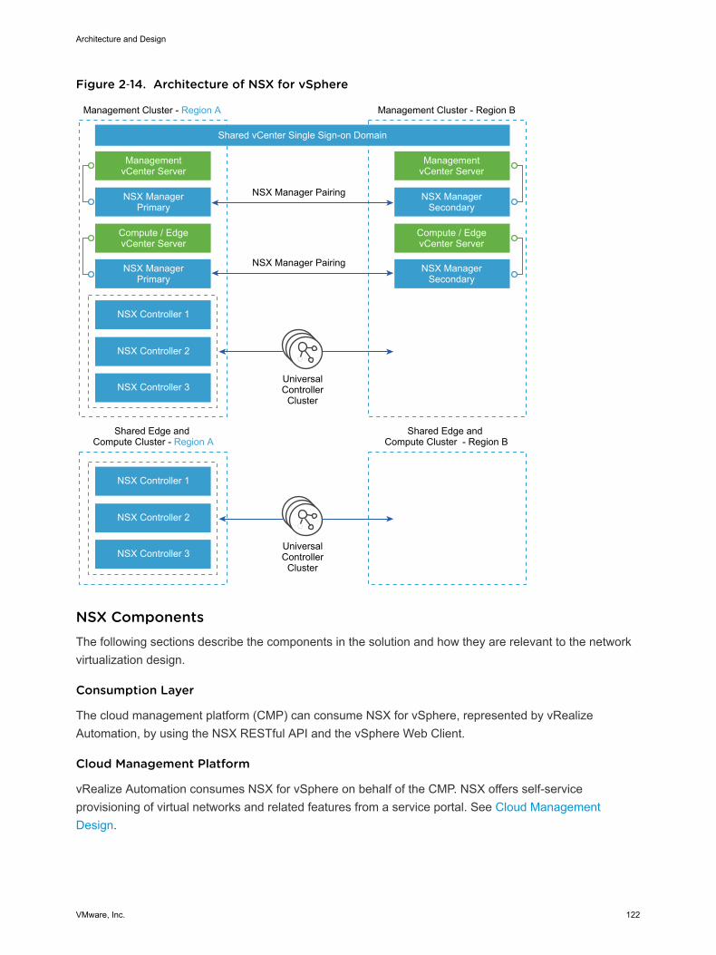
Figure 2‑14. Architecture of NSX for vSphere
UniversalController
Cluster
UniversalController
Cluster
Management Cluster - Region A
Shared Edge and Compute Cluster - Region A
Shared Edge and Compute Cluster - Region B
Shared vCenter Single Sign-on Domain
NSX Manager Pairing
NSX Manager Pairing
ManagementvCenter Server
NSX ManagerPrimary
NSX ManagerPrimary
NSX Controller 1
NSX Controller 2
NSX Controller 3
NSX Controller 1
NSX Controller 2
NSX Controller 3
Compute / EdgevCenter Server
Management Cluster - Region B
ManagementvCenter Server
NSX ManagerSecondary
NSX ManagerSecondary
Compute / EdgevCenter Server
NSX Components The following sections describe the components in the solution and how they are relevant to the networkvirtualization design.
Consumption Layer
The cloud management platform (CMP) can consume NSX for vSphere, represented by vRealizeAutomation, by using the NSX RESTful API and the vSphere Web Client.
Cloud Management Platform
vRealize Automation consumes NSX for vSphere on behalf of the CMP. NSX offers self-serviceprovisioning of virtual networks and related features from a service portal. See Cloud ManagementDesign.
Architecture and Design
VMware, Inc. 122
API
NSX for vSphere offers a powerful management interface through its REST API.
n A client can read an object by making an HTTP GET request to the resource URL of the object.
n A client can write (create or modify) an object using an HTTP PUT or POST request that includes anew or changed XML document for the object.
n A client can delete an object with an HTTP DELETE request.
vSphere Web Client
The NSX Manager component provides a networking and security plug-in in the vSphere Web Client. Thisplug-in provides an interface for using virtualized networking from NSX Manager for users with sufficientprivileges.
Table 2‑67. Design Decisions on the NSX Consumption Method
DecisionID Design Decision Design Justification Design Implications
SDDC-VI-SDN-003
For the shared edge and computecluster NSX instance, end-useraccess is accomplished by usingvRealize Automation services.Administrators use both thevSphere Web Client and the NSXREST API.
vRealize Automation services are used for thecustomer-facing portal. The vSphere WebClient consumes NSX for vSphere resourcesthrough the Network and Security plug-in. TheNSX REST API offers the potential of scriptingrepeating actions and operations.
Customers typicallyinteract only indirectly withNSX from the vRealizeAutomation portal.Administrators interactwith NSX from thevSphere Web Client andAPI.
SDDC-VI-SDN-004
For the management cluster NSXinstance, consumption is only byprovider staff using the vSphereWeb Client and the API.
Ensures that infrastructure components are notmodified by tenants or non-provider staff.
Tenants do not haveaccess to themanagement stackworkloads.
NSX Manager
NSX Manager provides the centralized management plane for NSX for vSphere and has a one-to-onemapping to vCenter Server workloads.
NSX Manager performs the following functions.
n Provides the single point of configuration and the REST API entry-points for NSX in a vSphereenvironment.
n Deploys NSX Controller clusters, Edge distributed routers, and Edge service gateways in the form ofOVF appliances, guest introspection services, and so on.
n Prepares ESXi hosts for NSX by installing VXLAN, distributed routing and firewall kernel modules,and the User World Agent (UWA).
n Communicates with NSX Controller clusters over REST and with ESXi hosts over the RabbitMQmessage bus. This internal message bus is specific to NSX for vSphere and does not require setup ofadditional services.
Architecture and Design
VMware, Inc. 123
n Generates certificates for the NSX Controller instances and ESXi hosts to secure control planecommunications with mutual authentication.
NSX Controller
An NSX Controller performs the following functions.
n Provides the control plane to distribute VXLAN and logical routing information to ESXi hosts.
n Includes nodes that are clustered for scale-out and high availability.
n Slices network information across cluster nodes for redundancy.
n Removes requirement of VXLAN Layer 3 multicast in the physical network.
n Provides ARP suppression of broadcast traffic in VXLAN networks.
NSX control plane communication occurs over the management network.
Table 2‑68. Design Decisions on the NSX Controller Instances
DecisionID Design Decision Design Justification Design Implications
SDDC-VI-SDN-005
Deploy NSX Controller instances in Universal Clustermode with three members to provide high availabilityand scale. Provision these three nodes through theprimary NSX Manager instance.
The high availability ofNSX Controllerreduces the downtimeperiod in case offailure of one physicalESXi host.
The secondary NSX Managerdoes not deploy controllers.
The controllers from the primaryNSX Manager manage allsecondary resources.
NSX Virtual Switch
The NSX data plane consists of the NSX virtual switch. This virtual switch is based on the vSphereDistributed Switch (VDS) with additional components to enable rich services. The add-on NSXcomponents include kernel modules (VIBs) which run within the hypervisor kernel and provide servicessuch as distributed logical router (DLR) and distributed firewall (DFW), and VXLAN capabilities.
The NSX virtual switch abstracts the physical network and provides access-level switching in thehypervisor. It is central to network virtualization because it enables logical networks that are independentof physical constructs such as VLAN. Using an NSX virtual switch includes several benefits.
n Supports overlay networking and centralized network configuration. Overlay networking enables thefollowing capabilities.
n Facilitates massive scale of hypervisors.
n Because the NSX virtual switch is based on VDS, it provides a comprehensive toolkit for trafficmanagement, monitoring, and troubleshooting within a virtual network through features such as portmirroring, NetFlow/IPFIX, configuration backup and restore, network health check, QoS, and more.
Architecture and Design
VMware, Inc. 124
Logical Switching
NSX logical switches create logically abstracted segments to which tenant virtual machines can beconnected. A single logical switch is mapped to a unique VXLAN segment and is distributed across theESXi hypervisors within a transport zone. The logical switch allows line-rate switching in the hypervisorwithout the constraints of VLAN sprawl or spanning tree issues.
Distributed Logical Router
The NSX distributed logical router (DLR) is optimized for forwarding in the virtualized space, that is,forwarding between VMs on VXLAN- or VLAN-backed port groups. DLR has the following characteristics.
n High performance, low overhead first hop routing
n Scales with number of ESXi hosts
n Up to 1,000 Logical Interfaces (LIFs) on each DLR
Distributed Logical Router Control Virtual Machine
The distributed logical router control virtual machine is the control plane component of the routingprocess, providing communication between NSX Manager and the NSX Controller cluster through theUser World Agent (UWA). NSX Manager sends logical interface information to the control virtual machineand the NSX Controller cluster, and the control virtual machine sends routing updates to the NSXController cluster.
User World Agent
The User World Agent (UWA) is a TCP (SSL) client that facilitates communication between the ESXihosts and the NSX Controller instances as well as the retrieval of information from the NSX Manager viainteraction with the message bus agent.
VXLAN Tunnel Endpoint
VXLAN Tunnel Endpoints (VTEPs) are instantiated within the vSphere Distributed Switch to which theESXi hosts that are prepared for NSX for vSphere are connected. VTEPs are responsible forencapsulating VXLAN traffic as frames in UDP packets and for the corresponding decapsulation. VTEPstake the form of one or more VMkernel ports with IP addresses and are used both to exchange packetswith other VTEPs and to join IP multicast groups via Internet Group Membership Protocol (IGMP). If youuse multiple VTEPs, then you must select a teaming method.
Edge Services Gateway
The NSX Edge services gateways (ESGs) primary function is north/south communication, but it alsooffers support for Layer 2, Layer 3, perimeter firewall, load balancing and other services such as SSL-VPN and DHCP-relay.
Architecture and Design
VMware, Inc. 125
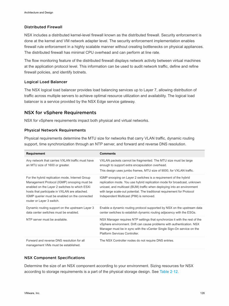
Distributed Firewall
NSX includes a distributed kernel-level firewall known as the distributed firewall. Security enforcement isdone at the kernel and VM network adapter level. The security enforcement implementation enablesfirewall rule enforcement in a highly scalable manner without creating bottlenecks on physical appliances.The distributed firewall has minimal CPU overhead and can perform at line rate.
The flow monitoring feature of the distributed firewall displays network activity between virtual machinesat the application protocol level. This information can be used to audit network traffic, define and refinefirewall policies, and identify botnets.
Logical Load Balancer
The NSX logical load balancer provides load balancing services up to Layer 7, allowing distribution oftraffic across multiple servers to achieve optimal resource utilization and availability. The logical loadbalancer is a service provided by the NSX Edge service gateway.
NSX for vSphere Requirements NSX for vSphere requirements impact both physical and virtual networks.
Physical Network Requirements
Physical requirements determine the MTU size for networks that carry VLAN traffic, dynamic routingsupport, time synchronization through an NTP server, and forward and reverse DNS resolution.
Requirement Comments
Any network that carries VXLAN traffic must havean MTU size of 1600 or greater.
VXLAN packets cannot be fragmented. The MTU size must be largeenough to support extra encapsulation overhead.
This design uses jumbo frames, MTU size of 9000, for VXLAN traffic.
For the hybrid replication mode, Internet GroupManagement Protocol (IGMP) snooping must beenabled on the Layer 2 switches to which ESXihosts that participate in VXLAN are attached.IGMP querier must be enabled on the connectedrouter or Layer 3 switch.
IGMP snooping on Layer 2 switches is a requirement of the hybridreplication mode. You use hybrid replication mode for broadcast, unknownunicast, and multicast (BUM) traffic when deploying into an environmentwith large scale-out potential. The traditional requirement for ProtocolIndependent Multicast (PIM) is removed.
Dynamic routing support on the upstream Layer 3data center switches must be enabled.
Enable a dynamic routing protocol supported by NSX on the upstream datacenter switches to establish dynamic routing adjacency with the ESGs.
NTP server must be available. NSX Manager requires NTP settings that synchronize it with the rest of thevSphere environment. Drift can cause problems with authentication. NSXManager must be in sync with the vCenter Single Sign-On service on thePlatform Services Controller.
Forward and reverse DNS resolution for allmanagement VMs must be established.
The NSX Controller nodes do not require DNS entries.
NSX Component Specifications
Determine the size of an NSX component according to your environment. Sizing resources for NSXaccording to storage requirements is a part of the physical storage design. See Table 2‑12.
Architecture and Design
VMware, Inc. 126
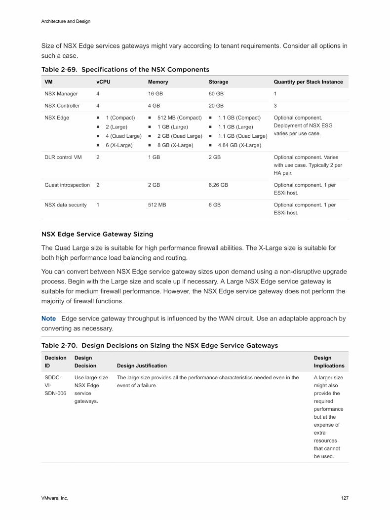
Size of NSX Edge services gateways might vary according to tenant requirements. Consider all options insuch a case.
Table 2‑69. Specifications of the NSX Components
VM vCPU Memory Storage Quantity per Stack Instance
NSX Manager 4 16 GB 60 GB 1
NSX Controller 4 4 GB 20 GB 3
NSX Edge n 1 (Compact)n 2 (Large)n 4 (Quad Large)n 6 (X-Large)
n 512 MB (Compact)n 1 GB (Large)n 2 GB (Quad Large)n 8 GB (X-Large)
n 1.1 GB (Compact)n 1.1 GB (Large)n 1.1 GB (Quad Large)n 4.84 GB (X-Large)
Optional component.Deployment of NSX ESGvaries per use case.
DLR control VM 2 1 GB 2 GB Optional component. Varieswith use case. Typically 2 perHA pair.
Guest introspection 2 2 GB 6.26 GB Optional component. 1 perESXi host.
NSX data security 1 512 MB 6 GB Optional component. 1 perESXi host.
NSX Edge Service Gateway Sizing
The Quad Large size is suitable for high performance firewall abilities. The X-Large size is suitable forboth high performance load balancing and routing.
You can convert between NSX Edge service gateway sizes upon demand using a non-disruptive upgradeprocess. Begin with the Large size and scale up if necessary. A Large NSX Edge service gateway issuitable for medium firewall performance. However, the NSX Edge service gateway does not perform themajority of firewall functions.
Note Edge service gateway throughput is influenced by the WAN circuit. Use an adaptable approach byconverting as necessary.
Table 2‑70. Design Decisions on Sizing the NSX Edge Service Gateways
DecisionID
DesignDecision Design Justification
DesignImplications
SDDC-VI-SDN-006
Use large-sizeNSX Edgeservicegateways.
The large size provides all the performance characteristics needed even in theevent of a failure.
A larger sizemight alsoprovide therequiredperformancebut at theexpense ofextraresourcesthat cannotbe used.
Architecture and Design
VMware, Inc. 127
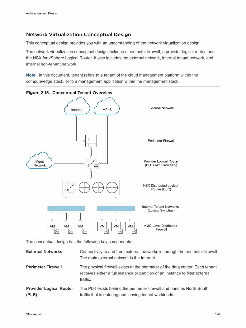
Network Virtualization Conceptual Design This conceptual design provides you with an understanding of the network virtualization design.
The network virtualization conceptual design includes a perimeter firewall, a provider logical router, andthe NSX for vSphere Logical Router. It also includes the external network, internal tenant network, andinternal non-tenant network.
Note In this document, tenant refers to a tenant of the cloud management platform within thecompute/edge stack, or to a management application within the management stack.
Figure 2‑15. Conceptual Tenant Overview
VM VMVM VM VMVM
Internet MPLS
MgmtNetwork
External Network
Perimeter Firewall
Provider Logical Router(PLR) with Firewalling
NSX Distributed Logical Router (DLR)
Internal Tenant Networks (Logical Switches)
vNIC-Level Distributed Firewall
The conceptual design has the following key components.
External Networks Connectivity to and from external networks is through the perimeter firewall.The main external network is the Internet.
Perimeter Firewall The physical firewall exists at the perimeter of the data center. Each tenantreceives either a full instance or partition of an instance to filter externaltraffic.
Provider Logical Router(PLR)
The PLR exists behind the perimeter firewall and handles North-Southtraffic that is entering and leaving tenant workloads.
Architecture and Design
VMware, Inc. 128
NSX Distributed LogicalRouter (DLR)
This logical router is optimized for forwarding in the virtualized space, thatis, between VMs, on VXLAN port groups or VLAN-backed port groups.
Management Network The management network is a VLAN-backed network that supports allmanagement components such as vCenter Server, Platform ServicesController, NSX Manager and NSX Controllers, and Update ManagerDownload Service (UMDS).
In a dual-region environment, this network also handles Site RecoveryManager traffic.
Internal Non-TenantNetwork
A single management network, which sits behind the perimeter firewall butnot behind the PLR. Enables customers to manage the tenantenvironments.
Internal TenantNetworks
Connectivity for the main tenant workload. These networks are connectedto a DLR, which sits behind the PLR. These networks take the form ofVXLAN-based NSX for vSphere logical switches. Tenant virtual machineworkloads will be directly attached to these networks.
Cluster Design for NSX for vSphere Following the vSphere design, the NSX for vSphere design consists of a management stack and acompute/edge stack in each region.
Architecture and Design
VMware, Inc. 129
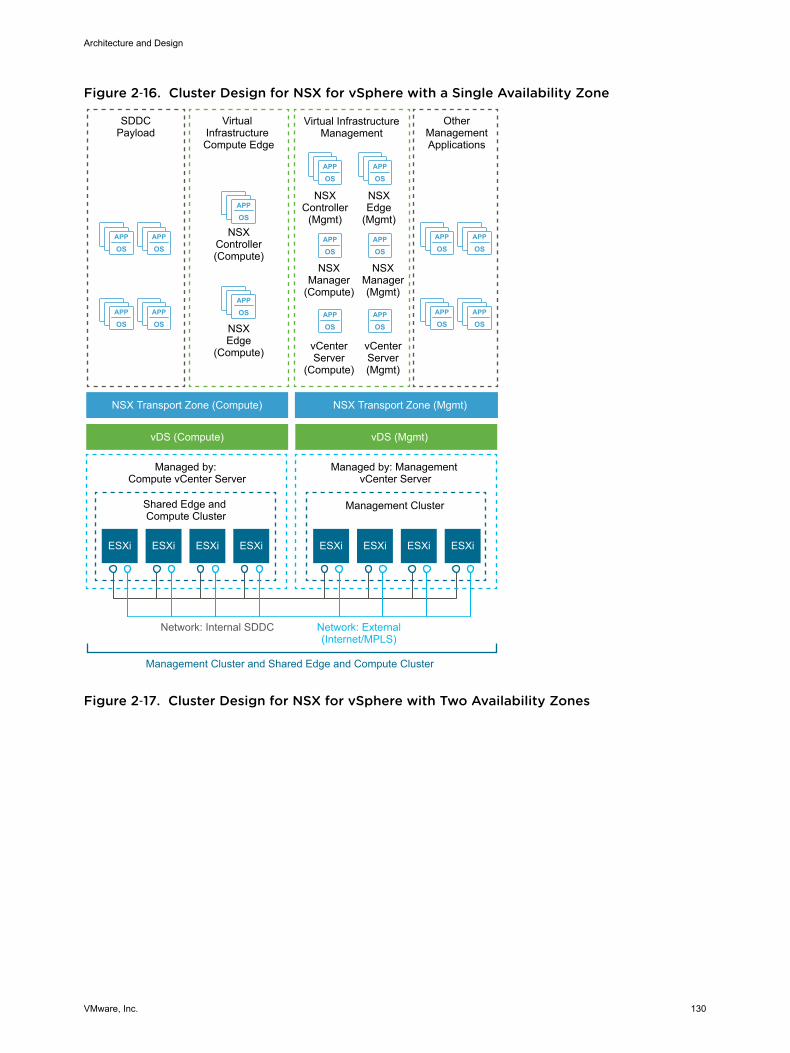
Figure 2‑16. Cluster Design for NSX for vSphere with a Single Availability Zone
APP
OSAPP
OS
APP
OSAPP
OS
APP
OSAPP
OS
APP
OSAPP
OS
APP
OS
APP
OS
APP
OSAPP
OS
APP
OSAPP
OS
APP
OSAPP
OS
Virtual InfrastructureManagement
NSXController
(Mgmt)
OtherManagementApplications
NSXEdge
(Mgmt)
NSXManager(Mgmt)
NSXManager
(Compute)
NSXEdge
(Compute)
NSXController(Compute)
ESXi ESXi ESXi ESXi ESXi ESXi
SDDCPayload
Virtual Infrastructure Compute Edge
NSX Transport Zone (Compute)
vDS (Compute) vDS (Mgmt)
NSX Transport Zone (Mgmt)
Shared Edge and Compute Cluster
Management Cluster
Managed by: Compute vCenter Server
Managed by: Management vCenter Server
Network: External(Internet/MPLS)
Network: Internal SDDC
Management Cluster and Shared Edge and Compute Cluster
vCenterServer(Mgmt)
vCenterServer
(Compute)
ESXi ESXi
Figure 2‑17. Cluster Design for NSX for vSphere with Two Availability Zones
Architecture and Design
VMware, Inc. 130
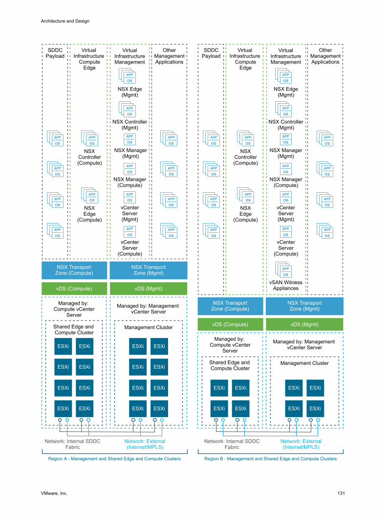
APP
OS
APP
OS
APP
OS
APP
OSAPP
OS
APP
OS
APP
OS
APP
OS
ESXi
APP
OS
APP
OS
APP
OS
APP
OS
APP
OS
APP
OS
APP
OS
APP
OS
APP
OS
APP
OS
APP
OS
APP
OS
APP
OS
APP
OS
APP
OS
APP
OS
APP
OS
APP
OS
APP
OS
APP
OS
APP
OSAPP
OS
APP
OS
APP
OS
APP
OS
VirtualInfrastructureManagement
NSX Controller(Mgmt)
OtherManagementApplications
NSX Edge(Mgmt)
NSX Manager(Mgmt)
NSX Manager(Compute)
NSXEdge
(Compute)
NSXController(Compute)
ESXi
ESXi ESXi
SDDCPayload
Virtual Infrastructure
ComputeEdge
NSX TransportZone (Compute)
vDS (Compute) vDS (Mgmt)
NSX TransportZone (Mgmt)
Shared Edge and Compute Cluster
Management Cluster
Managed by: Compute vCenter
Server
Managed by: Management vCenter Server
Network: External(Internet/MPLS)
Network: Internal SDDCFabric
Region A - Management and Shared Edge and Compute Clusters
vCenterServer(Mgmt)
vCenterServer
(Compute)
ESXiESXi
ESXi ESXi
ESXiESXi
ESXi ESXi
ESXiESXi
ESXi ESXi
ESXi
VirtualInfrastructureManagement
NSX Controller(Mgmt)
OtherManagementApplications
NSX Edge(Mgmt)
NSX Manager(Mgmt)
NSX Manager(Compute)
NSXEdge
(Compute)
NSXController(Compute)
ESXi
ESXi ESXi
SDDCPayload
Virtual Infrastructure
ComputeEdge
NSX TransportZone (Compute)
vDS (Compute) vDS (Mgmt)
NSX TransportZone (Mgmt)
Shared Edge and Compute Cluster
Management Cluster
Managed by: Compute vCenter
Server
Managed by: Management vCenter Server
Network: External(Internet/MPLS)
Network: Internal SDDCFabric
Region B - Management and Shared Edge and Compute Clusters
vCenterServer(Mgmt)
vCenterServer
(Compute)
ESXiESXi
ESXi ESXi
vSAN WitnessAppliances
Architecture and Design
VMware, Inc. 131
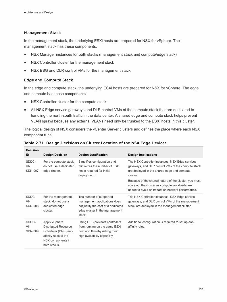
Management Stack
In the management stack, the underlying ESXi hosts are prepared for NSX for vSphere. Themanagement stack has these components.
n NSX Manager instances for both stacks (management stack and compute/edge stack)
n NSX Controller cluster for the management stack
n NSX ESG and DLR control VMs for the management stack
Edge and Compute Stack
In the edge and compute stack, the underlying ESXi hosts are prepared for NSX for vSphere. The edgeand compute has these components.
n NSX Controller cluster for the compute stack.
n All NSX Edge service gateways and DLR control VMs of the compute stack that are dedicated tohandling the north-south traffic in the data center. A shared edge and compute stack helps preventVLAN sprawl because any external VLANs need only be trunked to the ESXi hosts in this cluster.
The logical design of NSX considers the vCenter Server clusters and defines the place where each NSXcomponent runs.
Table 2‑71. Design Decisions on Cluster Location of the NSX Edge Devices
DecisionID Design Decision Design Justification Design Implications
SDDC-VI-SDN-007
For the compute stack,do not use a dedicatededge cluster.
Simplifies configuration andminimizes the number of ESXihosts required for initialdeployment.
The NSX Controller instances, NSX Edge servicesgateways, and DLR control VMs of the compute stackare deployed in the shared edge and computecluster.
Because of the shared nature of the cluster, you mustscale out the cluster as compute workloads areadded to avoid an impact on network performance.
SDDC-VI-SDN-008
For the managementstack, do not use adedicated edgecluster.
The number of supportedmanagement applications doesnot justify the cost of a dedicatededge cluster in the managementstack.
The NSX Controller instances, NSX Edge servicegateways, and DLR control VMs of the managementstack are deployed in the management cluster.
SDDC-VI-SDN-009
Apply vSphereDistributed ResourceScheduler (DRS) anti-affinity rules to theNSX components inboth stacks.
Using DRS prevents controllersfrom running on the same ESXihost and thereby risking theirhigh availability capability.
Additional configuration is required to set up anti-affinity rules.
Architecture and Design
VMware, Inc. 132
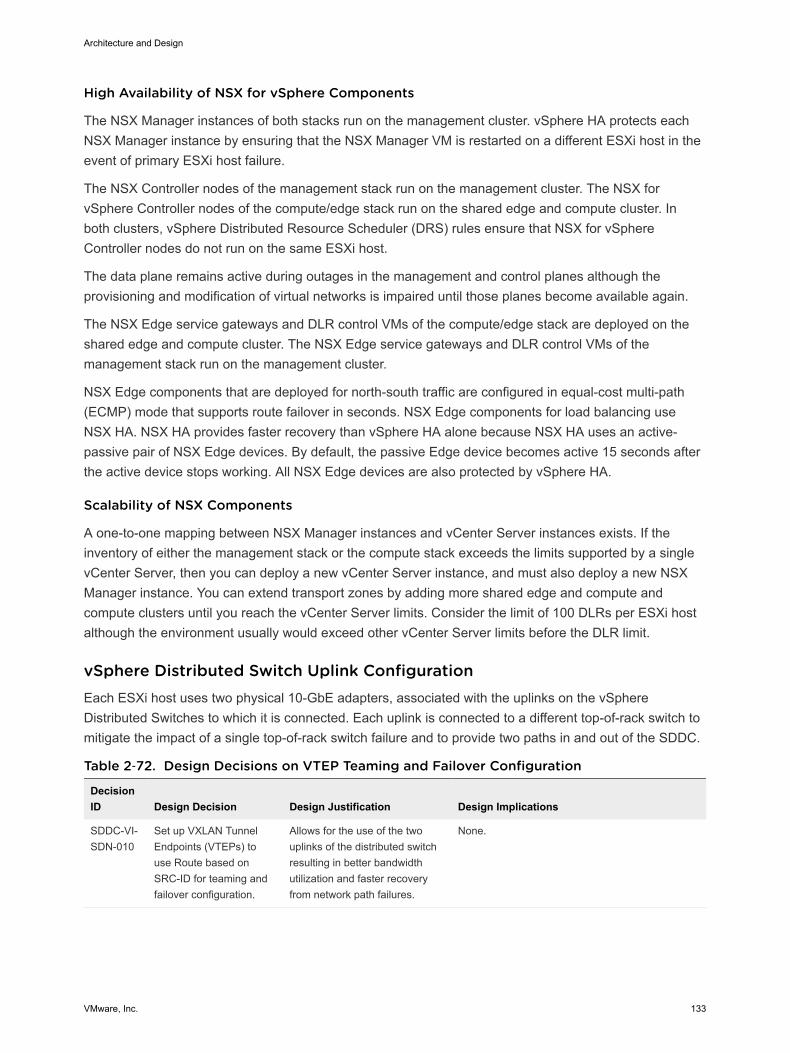
High Availability of NSX for vSphere Components
The NSX Manager instances of both stacks run on the management cluster. vSphere HA protects eachNSX Manager instance by ensuring that the NSX Manager VM is restarted on a different ESXi host in theevent of primary ESXi host failure.
The NSX Controller nodes of the management stack run on the management cluster. The NSX forvSphere Controller nodes of the compute/edge stack run on the shared edge and compute cluster. Inboth clusters, vSphere Distributed Resource Scheduler (DRS) rules ensure that NSX for vSphereController nodes do not run on the same ESXi host.
The data plane remains active during outages in the management and control planes although theprovisioning and modification of virtual networks is impaired until those planes become available again.
The NSX Edge service gateways and DLR control VMs of the compute/edge stack are deployed on theshared edge and compute cluster. The NSX Edge service gateways and DLR control VMs of themanagement stack run on the management cluster.
NSX Edge components that are deployed for north-south traffic are configured in equal-cost multi-path(ECMP) mode that supports route failover in seconds. NSX Edge components for load balancing useNSX HA. NSX HA provides faster recovery than vSphere HA alone because NSX HA uses an active-passive pair of NSX Edge devices. By default, the passive Edge device becomes active 15 seconds afterthe active device stops working. All NSX Edge devices are also protected by vSphere HA.
Scalability of NSX Components
A one-to-one mapping between NSX Manager instances and vCenter Server instances exists. If theinventory of either the management stack or the compute stack exceeds the limits supported by a singlevCenter Server, then you can deploy a new vCenter Server instance, and must also deploy a new NSXManager instance. You can extend transport zones by adding more shared edge and compute andcompute clusters until you reach the vCenter Server limits. Consider the limit of 100 DLRs per ESXi hostalthough the environment usually would exceed other vCenter Server limits before the DLR limit.
vSphere Distributed Switch Uplink Configuration Each ESXi host uses two physical 10-GbE adapters, associated with the uplinks on the vSphereDistributed Switches to which it is connected. Each uplink is connected to a different top-of-rack switch tomitigate the impact of a single top-of-rack switch failure and to provide two paths in and out of the SDDC.
Table 2‑72. Design Decisions on VTEP Teaming and Failover Configuration
DecisionID Design Decision Design Justification Design Implications
SDDC-VI-SDN-010
Set up VXLAN TunnelEndpoints (VTEPs) touse Route based onSRC-ID for teaming andfailover configuration.
Allows for the use of the twouplinks of the distributed switchresulting in better bandwidthutilization and faster recoveryfrom network path failures.
None.
Architecture and Design
VMware, Inc. 133
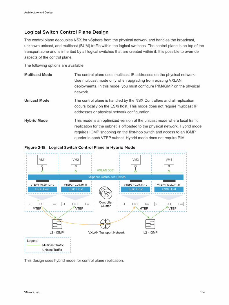
Logical Switch Control Plane Design The control plane decouples NSX for vSphere from the physical network and handles the broadcast,unknown unicast, and multicast (BUM) traffic within the logical switches. The control plane is on top of thetransport zone and is inherited by all logical switches that are created within it. It is possible to overrideaspects of the control plane.
The following options are available.
Multicast Mode The control plane uses multicast IP addresses on the physical network.Use multicast mode only when upgrading from existing VXLANdeployments. In this mode, you must configure PIM/IGMP on the physicalnetwork.
Unicast Mode The control plane is handled by the NSX Controllers and all replicationoccurs locally on the ESXi host. This mode does not require multicast IPaddresses or physical network configuration.
Hybrid Mode This mode is an optimized version of the unicast mode where local trafficreplication for the subnet is offloaded to the physical network. Hybrid moderequires IGMP snooping on the first-hop switch and access to an IGMPquerier in each VTEP subnet. Hybrid mode does not require PIM.
Figure 2‑18. Logical Switch Control Plane in Hybrid Mode
VM1 VM2
vSphere Distributed Switch
ESXi Host
VXLAN 5001
VTEP1 10.20.10.10
ESXi HostVTEP2 10.20.10.11
VM3
ESXi HostVTEP3 10.20.11.10
VM4
ESXi HostVTEP4 10.20.11.11
MTEP VTEP MTEP VTEP
L2 - IGMP L2 - IGMP
Multicast TrafficUnicast Traffic
ControllerCluster
Legend:
VXLAN Transport Network
This design uses hybrid mode for control plane replication.
Architecture and Design
VMware, Inc. 134
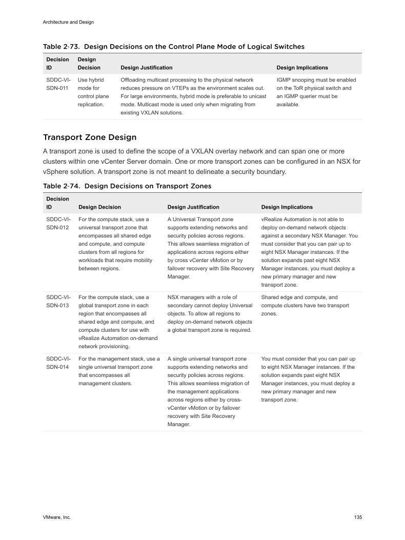
Table 2‑73. Design Decisions on the Control Plane Mode of Logical Switches
DecisionID
DesignDecision Design Justification Design Implications
SDDC-VI-SDN-011
Use hybridmode forcontrol planereplication.
Offloading multicast processing to the physical networkreduces pressure on VTEPs as the environment scales out.For large environments, hybrid mode is preferable to unicastmode. Multicast mode is used only when migrating fromexisting VXLAN solutions.
IGMP snooping must be enabledon the ToR physical switch andan IGMP querier must beavailable.
Transport Zone Design A transport zone is used to define the scope of a VXLAN overlay network and can span one or moreclusters within one vCenter Server domain. One or more transport zones can be configured in an NSX forvSphere solution. A transport zone is not meant to delineate a security boundary.
Table 2‑74. Design Decisions on Transport Zones
DecisionID Design Decision Design Justification Design Implications
SDDC-VI-SDN-012
For the compute stack, use auniversal transport zone thatencompasses all shared edgeand compute, and computeclusters from all regions forworkloads that require mobilitybetween regions.
A Universal Transport zonesupports extending networks andsecurity policies across regions.This allows seamless migration ofapplications across regions eitherby cross vCenter vMotion or byfailover recovery with Site RecoveryManager.
vRealize Automation is not able todeploy on-demand network objectsagainst a secondary NSX Manager. Youmust consider that you can pair up toeight NSX Manager instances. If thesolution expands past eight NSXManager instances, you must deploy anew primary manager and newtransport zone.
SDDC-VI-SDN-013
For the compute stack, use aglobal transport zone in eachregion that encompasses allshared edge and compute, andcompute clusters for use withvRealize Automation on-demandnetwork provisioning.
NSX managers with a role ofsecondary cannot deploy Universalobjects. To allow all regions todeploy on-demand network objectsa global transport zone is required.
Shared edge and compute, andcompute clusters have two transportzones.
SDDC-VI-SDN-014
For the management stack, use asingle universal transport zonethat encompasses allmanagement clusters.
A single universal transport zonesupports extending networks andsecurity policies across regions.This allows seamless migration ofthe management applicationsacross regions either by cross-vCenter vMotion or by failoverrecovery with Site RecoveryManager.
You must consider that you can pair upto eight NSX Manager instances. If thesolution expands past eight NSXManager instances, you must deploy anew primary manager and newtransport zone.
Architecture and Design
VMware, Inc. 135
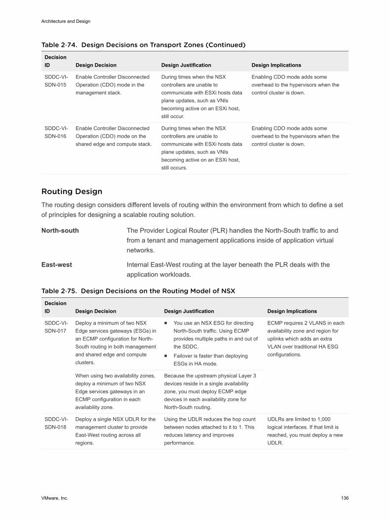
Table 2‑74. Design Decisions on Transport Zones (Continued)
DecisionID Design Decision Design Justification Design Implications
SDDC-VI-SDN-015
Enable Controller DisconnectedOperation (CDO) mode in themanagement stack.
During times when the NSXcontrollers are unable tocommunicate with ESXi hosts dataplane updates, such as VNIsbecoming active on an ESXi host,still occur.
Enabling CDO mode adds someoverhead to the hypervisors when thecontrol cluster is down.
SDDC-VI-SDN-016
Enable Controller DisconnectedOperation (CDO) mode on theshared edge and compute stack.
During times when the NSXcontrollers are unable tocommunicate with ESXi hosts dataplane updates, such as VNIsbecoming active on an ESXi host,still occurs.
Enabling CDO mode adds someoverhead to the hypervisors when thecontrol cluster is down.
Routing Design The routing design considers different levels of routing within the environment from which to define a setof principles for designing a scalable routing solution.
North-south The Provider Logical Router (PLR) handles the North-South traffic to andfrom a tenant and management applications inside of application virtualnetworks.
East-west Internal East-West routing at the layer beneath the PLR deals with theapplication workloads.
Table 2‑75. Design Decisions on the Routing Model of NSX
DecisionID Design Decision Design Justification Design Implications
SDDC-VI-SDN-017
Deploy a minimum of two NSXEdge services gateways (ESGs) inan ECMP configuration for North-South routing in both managementand shared edge and computeclusters.
n You use an NSX ESG for directingNorth-South traffic. Using ECMPprovides multiple paths in and out ofthe SDDC.
n Failover is faster than deployingESGs in HA mode.
ECMP requires 2 VLANS in eachavailability zone and region foruplinks which adds an extraVLAN over traditional HA ESGconfigurations.
When using two availability zones,deploy a minimum of two NSXEdge services gateways in anECMP configuration in eachavailability zone.
Because the upstream physical Layer 3devices reside in a single availabilityzone, you must deploy ECMP edgedevices in each availability zone forNorth-South routing.
SDDC-VI-SDN-018
Deploy a single NSX UDLR for themanagement cluster to provideEast-West routing across allregions.
Using the UDLR reduces the hop countbetween nodes attached to it to 1. Thisreduces latency and improvesperformance.
UDLRs are limited to 1,000logical interfaces. If that limit isreached, you must deploy a newUDLR.
Architecture and Design
VMware, Inc. 136
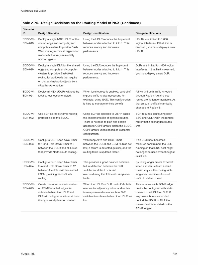
Table 2‑75. Design Decisions on the Routing Model of NSX (Continued)
DecisionID Design Decision Design Justification Design Implications
SDDC-VI-SDN-019
Deploy a single NSX UDLR for theshared edge and compute, andcompute clusters to provide East-West routing across all regions forworkloads that require mobilityacross regions.
Using the UDLR reduces the hop countbetween nodes attached to it to 1. Thisreduces latency and improvesperformance.
UDLRs are limited to 1,000logical interfaces. If that limit isreached , you must deploy a newUDLR.
SDDC-VI-SDN-020
Deploy a single DLR for the sharededge and compute and computeclusters to provide East-Westrouting for workloads that requireon demand network objects fromvRealize Automation.
Using the DLR reduces the hop countbetween nodes attached to it to 1. Thisreduces latency and improvesperformance.
DLRs are limited to 1,000 logicalinterfaces. If that limit is reached,you must deploy a new DLR.
SDDC-VI-SDN-021
Deploy all NSX UDLRs without thelocal egress option enabled.
When local egress is enabled, control ofingress traffic is also necessary, forexample, using NAT). This configurationis hard to manage for little benefit.
All North-South traffic is routedthrough Region A until thoseroutes are no longer available. Atthat time, all traffic dynamicallychanges to Region B.
SDDC-VI-SDN-022
Use BGP as the dynamic routingprotocol inside the SDDC.
Using BGP as opposed to OSPF easesthe implementation of dynamic routing.There is no need to plan and designaccess to OSPF area 0 inside the SDDC.OSPF area 0 varies based on customerconfiguration.
BGP requires configuring eachESG and UDLR with the remoterouter that it exchanges routeswith.
SDDC-VI-SDN-023
Configure BGP Keep Alive Timerto 1 and Hold Down Timer to 3between the UDLR and all ESGsthat provide North-South routing.
With Keep Alive and Hold Timersbetween the UDLR and ECMP ESGs setlow, a failure is detected quicker, and therouting table is updated faster.
If an ESXi host becomesresource constrained, the ESGrunning on that ESXi host mightno longer be used even though itis still up.
SDDC-VI-SDN-024
Configure BGP Keep Alive Timerto 4 and Hold Down Timer to 12between the ToR switches and allESGs providing North-Southrouting.
This provides a good balance betweenfailure detection between the ToRswitches and the ESGs andoverburdening the ToRs with keep alivetraffic.
By using longer timers to detectwhen a router is dead, a deadrouter stays in the routing tablelonger and continues to sendtraffic to a dead router.
SDDC-VI-SDN-025
Create one or more static routeson ECMP enabled edges forsubnets behind the UDLR andDLR with a higher admin cost thanthe dynamically learned routes.
When the UDLR or DLR control VM failsover router adjacency is lost and routesfrom upstream devices such as ToRswitches to subnets behind the UDLR arelost.
This requires each ECMP edgedevice be configured with staticroutes to the UDLR or DLR. Ifany new subnets are addedbehind the UDLR or DLR theroutes must be updated on theECMP edges.
Architecture and Design
VMware, Inc. 137

Table 2‑75. Design Decisions on the Routing Model of NSX (Continued)
DecisionID Design Decision Design Justification Design Implications
SDDC-VI-SDN-026
Disable Graceful Restart on allECMP Edges and Logical RouterControl Virtual Machines.
Graceful Restart maintains theforwarding table which in turn will forwardpackets to a down neighbor even afterthe BGP timers have expired causingloss of traffic.
None.
SDDC-VI-SDN-027
In the management and sharededge and compute clusters, do notcreate anti-affinity rules to separateECMP edges and Logical Routercontrol virtual machines.
n Because these clusters contain fourhosts, creating an anti-affinity rulethat contains four virtual machinesresults in not being able to entermaintenance mode to perform lifecycle activities.
n During a host failure, vSphere HAcannot restart the virtual machinebecause of the anti-affinity rule.
If the active Logical Routercontrol virtual machine and anECMP edge reside on the samehost and that host fails, a deadpath in the routing table appearsuntil the standby Logical Routercontrol virtual machine starts itsrouting process and updates therouting tables.
To avoid this situation, add anadditional host to the cluster andcreate an anti-affinity rule to keepthese virtual machinesseparated.
Transit Network and Dynamic Routing
Dedicated networks are needed to facilitate traffic between the universal dynamic routers and edgegateways, and to facilitate traffic between edge gateways and the top of rack switches. These networksare used for exchanging routing tables and for carrying transit traffic.
Architecture and Design
VMware, Inc. 138
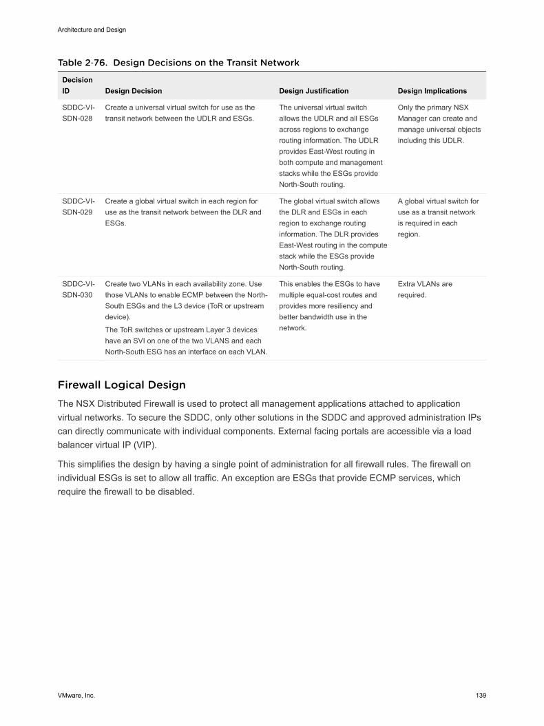
Table 2‑76. Design Decisions on the Transit Network
DecisionID Design Decision Design Justification Design Implications
SDDC-VI-SDN-028
Create a universal virtual switch for use as thetransit network between the UDLR and ESGs.
The universal virtual switchallows the UDLR and all ESGsacross regions to exchangerouting information. The UDLRprovides East-West routing inboth compute and managementstacks while the ESGs provideNorth-South routing.
Only the primary NSXManager can create andmanage universal objectsincluding this UDLR.
SDDC-VI-SDN-029
Create a global virtual switch in each region foruse as the transit network between the DLR andESGs.
The global virtual switch allowsthe DLR and ESGs in eachregion to exchange routinginformation. The DLR providesEast-West routing in the computestack while the ESGs provideNorth-South routing.
A global virtual switch foruse as a transit networkis required in eachregion.
SDDC-VI-SDN-030
Create two VLANs in each availability zone. Usethose VLANs to enable ECMP between the North-South ESGs and the L3 device (ToR or upstreamdevice).
The ToR switches or upstream Layer 3 deviceshave an SVI on one of the two VLANS and eachNorth-South ESG has an interface on each VLAN.
This enables the ESGs to havemultiple equal-cost routes andprovides more resiliency andbetter bandwidth use in thenetwork.
Extra VLANs arerequired.
Firewall Logical Design The NSX Distributed Firewall is used to protect all management applications attached to applicationvirtual networks. To secure the SDDC, only other solutions in the SDDC and approved administration IPscan directly communicate with individual components. External facing portals are accessible via a loadbalancer virtual IP (VIP).
This simplifies the design by having a single point of administration for all firewall rules. The firewall onindividual ESGs is set to allow all traffic. An exception are ESGs that provide ECMP services, whichrequire the firewall to be disabled.
Architecture and Design
VMware, Inc. 139
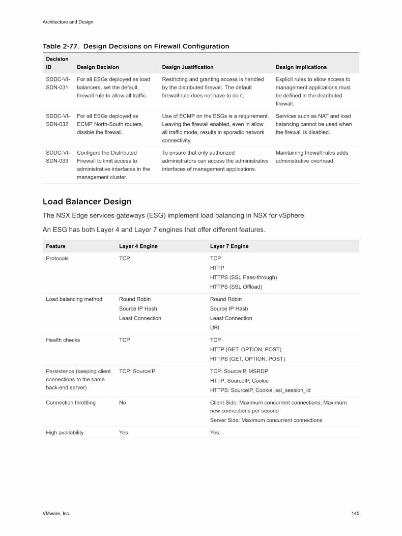
Table 2‑77. Design Decisions on Firewall Configuration
DecisionID Design Decision Design Justification Design Implications
SDDC-VI-SDN-031
For all ESGs deployed as loadbalancers, set the defaultfirewall rule to allow all traffic.
Restricting and granting access is handledby the distributed firewall. The defaultfirewall rule does not have to do it.
Explicit rules to allow access tomanagement applications mustbe defined in the distributedfirewall.
SDDC-VI-SDN-032
For all ESGs deployed asECMP North-South routers,disable the firewall.
Use of ECMP on the ESGs is a requirement.Leaving the firewall enabled, even in allowall traffic mode, results in sporadic networkconnectivity.
Services such as NAT and loadbalancing cannot be used whenthe firewall is disabled.
SDDC-VI-SDN-033
Configure the DistributedFirewall to limit access toadministrative interfaces in themanagement cluster.
To ensure that only authorizedadministrators can access the administrativeinterfaces of management applications.
Maintaining firewall rules addsadministrative overhead.
Load Balancer Design The NSX Edge services gateways (ESG) implement load balancing in NSX for vSphere.
An ESG has both Layer 4 and Layer 7 engines that offer different features.
Feature Layer 4 Engine Layer 7 Engine
Protocols TCP TCP
HTTP
HTTPS (SSL Pass-through)
HTTPS (SSL Offload)
Load balancing method Round Robin
Source IP Hash
Least Connection
Round Robin
Source IP Hash
Least Connection
URI
Health checks TCP TCP
HTTP (GET, OPTION, POST)
HTTPS (GET, OPTION, POST)
Persistence (keeping clientconnections to the sameback-end server)
TCP: SourceIP TCP: SourceIP, MSRDP
HTTP: SourceIP, Cookie
HTTPS: SourceIP, Cookie, ssl_session_id
Connection throttling No Client Side: Maximum concurrent connections, Maximumnew connections per second
Server Side: Maximum concurrent connections
High availability Yes Yes
Architecture and Design
VMware, Inc. 140
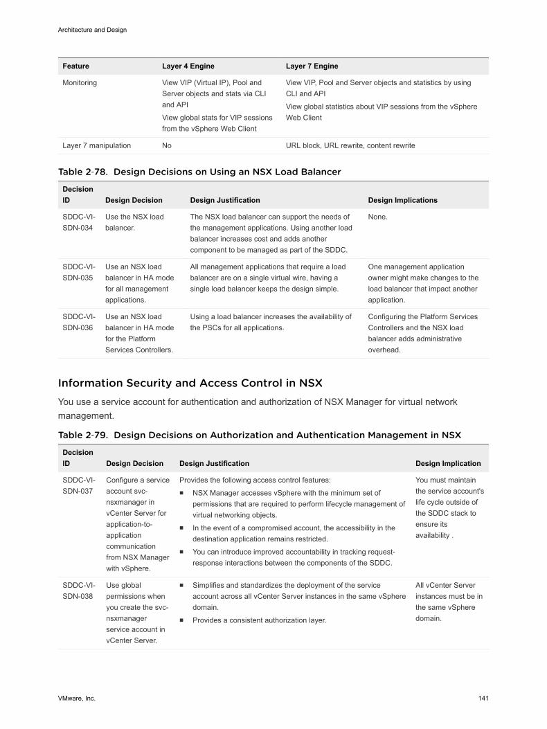
Feature Layer 4 Engine Layer 7 Engine
Monitoring View VIP (Virtual IP), Pool andServer objects and stats via CLIand API
View global stats for VIP sessionsfrom the vSphere Web Client
View VIP, Pool and Server objects and statistics by usingCLI and API
View global statistics about VIP sessions from the vSphereWeb Client
Layer 7 manipulation No URL block, URL rewrite, content rewrite
Table 2‑78. Design Decisions on Using an NSX Load Balancer
DecisionID Design Decision Design Justification Design Implications
SDDC-VI-SDN-034
Use the NSX loadbalancer.
The NSX load balancer can support the needs ofthe management applications. Using another loadbalancer increases cost and adds anothercomponent to be managed as part of the SDDC.
None.
SDDC-VI-SDN-035
Use an NSX loadbalancer in HA modefor all managementapplications.
All management applications that require a loadbalancer are on a single virtual wire, having asingle load balancer keeps the design simple.
One management applicationowner might make changes to theload balancer that impact anotherapplication.
SDDC-VI-SDN-036
Use an NSX loadbalancer in HA modefor the PlatformServices Controllers.
Using a load balancer increases the availability ofthe PSCs for all applications.
Configuring the Platform ServicesControllers and the NSX loadbalancer adds administrativeoverhead.
Information Security and Access Control in NSX You use a service account for authentication and authorization of NSX Manager for virtual networkmanagement.
Table 2‑79. Design Decisions on Authorization and Authentication Management in NSX
DecisionID Design Decision Design Justification Design Implication
SDDC-VI-SDN-037
Configure a serviceaccount svc-nsxmanager invCenter Server forapplication-to-applicationcommunicationfrom NSX Managerwith vSphere.
Provides the following access control features:n NSX Manager accesses vSphere with the minimum set of
permissions that are required to perform lifecycle management ofvirtual networking objects.
n In the event of a compromised account, the accessibility in thedestination application remains restricted.
n You can introduce improved accountability in tracking request-response interactions between the components of the SDDC.
You must maintainthe service account'slife cycle outside ofthe SDDC stack toensure itsavailability .
SDDC-VI-SDN-038
Use globalpermissions whenyou create the svc-nsxmanagerservice account invCenter Server.
n Simplifies and standardizes the deployment of the serviceaccount across all vCenter Server instances in the same vSpheredomain.
n Provides a consistent authorization layer.
All vCenter Serverinstances must be inthe same vSpheredomain.
Architecture and Design
VMware, Inc. 141
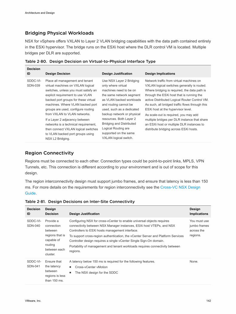
Bridging Physical Workloads NSX for vSphere offers VXLAN to Layer 2 VLAN bridging capabilities with the data path contained entirelyin the ESXi hypervisor. The bridge runs on the ESXi host where the DLR control VM is located. Multiplebridges per DLR are supported.
Table 2‑80. Design Decision on Virtual-to-Physical Interface Type
DecisionID Design Decision Design Justification Design Implications
SDDC-VI-SDN-039
Place all management and tenantvirtual machines on VXLAN logicalswitches, unless you must satisfy anexplicit requirement to use VLANbacked port groups for these virtualmachines. Where VLAN backed portgroups are used, configure routingfrom VXLAN to VLAN networks.
If a Layer 2 adjacency betweennetworks is a technical requirement,then connect VXLAN logical switchesto VLAN backed port groups usingNSX L2 Bridging.
Use NSX Layer 2 Bridgingonly where virtualmachines need to be onthe same network segmentas VLAN backed workloadsand routing cannot beused, such as a dedicatedbackup network or physicalresources. Both Layer 2Bridging and DistributedLogical Routing aresupported on the sameVXLAN logical switch.
Network traffic from virtual machines onVXLAN logical switches generally is routed.Where bridging is required, the data path isthrough the ESXi host that is running theactive Distributed Logical Router Control VM.As such, all bridged traffic flows through thisESXi host at the hypervisor level.
As scale-out is required, you may addmultiple bridges per DLR instance that sharean ESXi host or multiple DLR instances todistribute bridging across ESXi hosts.
Region Connectivity Regions must be connected to each other. Connection types could be point-to-point links, MPLS, VPNTunnels, etc. This connection is different according to your environment and is out of scope for thisdesign.
The region interconnectivity design must support jumbo frames, and ensure that latency is less than 150ms. For more details on the requirements for region interconnectivity see the Cross-VC NSX DesignGuide.
Table 2‑81. Design Decisions on Inter-Site Connectivity
DecisionID
DesignDecision Design Justification
DesignImplications
SDDC-VI-SDN-040
Provide aconnectionbetweenregions that iscapable ofroutingbetween eachcluster.
Configuring NSX for cross-vCenter to enable universal objects requiresconnectivity between NSX Manager instances, ESXi host VTEPs, and NSXControllers to ESXi hosts management interface.
To support cross-region authentication, the vCenter Server and Platform ServicesController design requires a single vCenter Single Sign-On domain.
Portability of management and tenant workloads requires connectivity betweenregions.
You must usejumbo framesacross theregions.
SDDC-VI-SDN-041
Ensure thatthe latencybetweenregions is lessthan 150 ms.
A latency below 150 ms is required for the following features.n Cross-vCenter vMotionn The NSX design for the SDDC
None.
Architecture and Design
VMware, Inc. 142
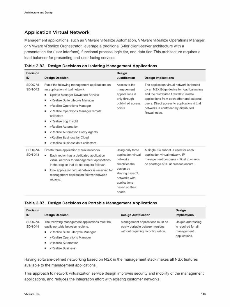
Application Virtual Network Management applications, such as VMware vRealize Automation, VMware vRealize Operations Manager,or VMware vRealize Orchestrator, leverage a traditional 3-tier client-server architecture with apresentation tier (user interface), functional process logic tier, and data tier. This architecture requires aload balancer for presenting end-user facing services.
Table 2‑82. Design Decisions on Isolating Management Applications
DecisionID Design Decision
DesignJustification Design Implications
SDDC-VI-SDN-042
Place the following management applications onan application virtual network.n Update Manager Download Servicen vRealize Suite Lifecyle Managern vRealize Operations Managern vRealize Operations Manager remote
collectorsn vRealize Log Insightn vRealize Automationn vRealize Automation Proxy Agentsn vRealize Business for Cloudn vRealize Business data collectors
Access to themanagementapplications isonly throughpublished accesspoints.
The application virtual network is frontedby an NSX Edge device for load balancingand the distributed firewall to isolateapplications from each other and externalusers. Direct access to application virtualnetworks is controlled by distributedfirewall rules.
SDDC-VI-SDN-043
Create three application virtual networks.n Each region has a dedicated application
virtual network for management applicationsin that region that do not require failover.
n One application virtual network is reserved formanagement application failover betweenregions.
Using only threeapplication virtualnetworkssimplifies thedesign bysharing Layer 2networks withapplicationsbased on theirneeds.
A single /24 subnet is used for eachapplication virtual network. IPmanagement becomes critical to ensureno shortage of IP addresses occurs.
Table 2‑83. Design Decisions on Portable Management Applications
DecisionID Design Decision Design Justification
DesignImplications
SDDC-VI-SDN-044
The following management applications must beeasily portable between regions.n vRealize Suite Lifecycle Managern vRealize Operations Managern vRealize Automationn vRealize Business
Management applications must beeasily portable between regionswithout requiring reconfiguration.
Unique addressingis required for allmanagementapplications.
Having software-defined networking based on NSX in the management stack makes all NSX featuresavailable to the management applications.
This approach to network virtualization service design improves security and mobility of the managementapplications, and reduces the integration effort with existing customer networks.
Architecture and Design
VMware, Inc. 143
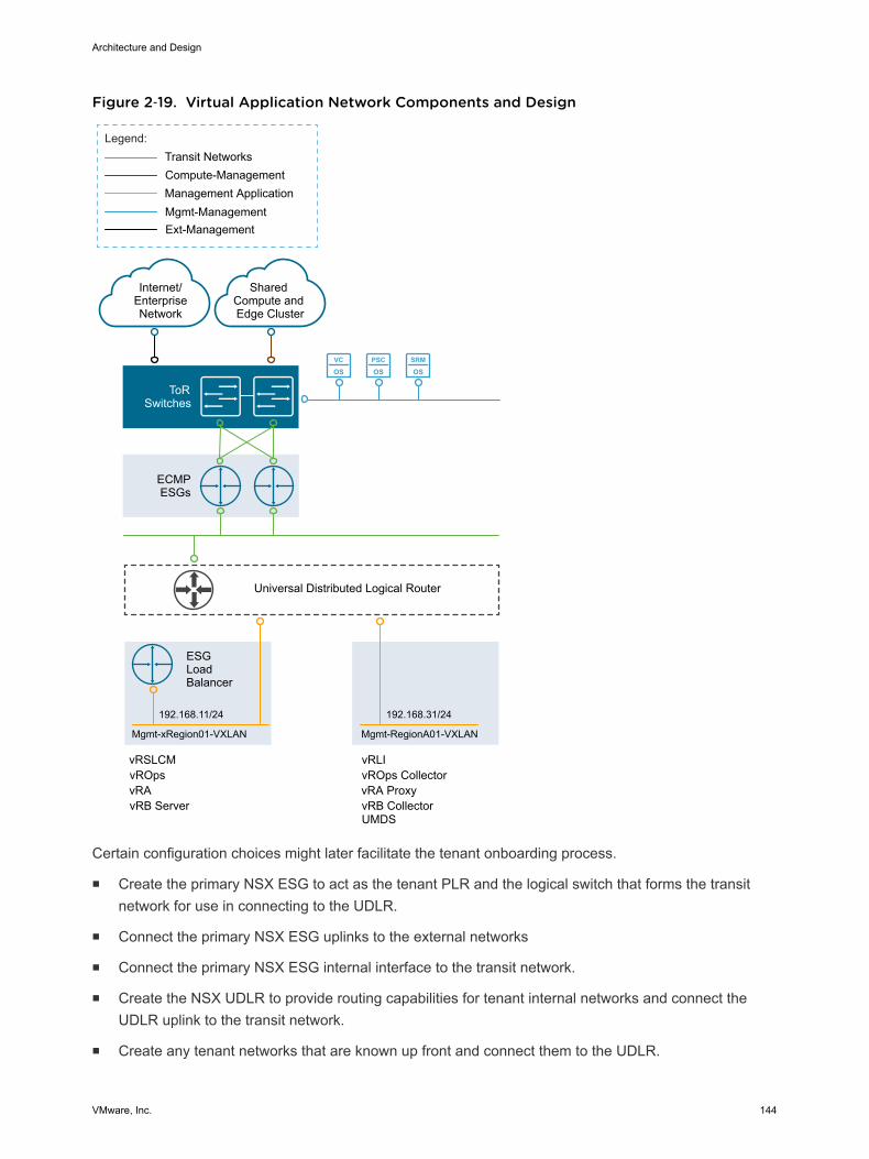
Figure 2‑19. Virtual Application Network Components and Design
VC
OSPSC
OSSRM
OS
ECMPESGs
ToRSwitches
Internet/EnterpriseNetwork
Mgmt-Management
Compute-Management
Legend:
Shared Compute and Edge Cluster
192.168.11/24
Transit Networks
Management Application
vRAvROps
Universal Distributed Logical Router
ESGLoadBalancer
Mgmt-xRegion01-VXLAN
192.168.31/24
Mgmt-RegionA01-VXLAN
Ext-Management
vRB Server
vRLIvRSLCMvROps CollectorvRA Proxy
UMDSvRB Collector
Certain configuration choices might later facilitate the tenant onboarding process.
n Create the primary NSX ESG to act as the tenant PLR and the logical switch that forms the transitnetwork for use in connecting to the UDLR.
n Connect the primary NSX ESG uplinks to the external networks
n Connect the primary NSX ESG internal interface to the transit network.
n Create the NSX UDLR to provide routing capabilities for tenant internal networks and connect theUDLR uplink to the transit network.
n Create any tenant networks that are known up front and connect them to the UDLR.
Architecture and Design
VMware, Inc. 144
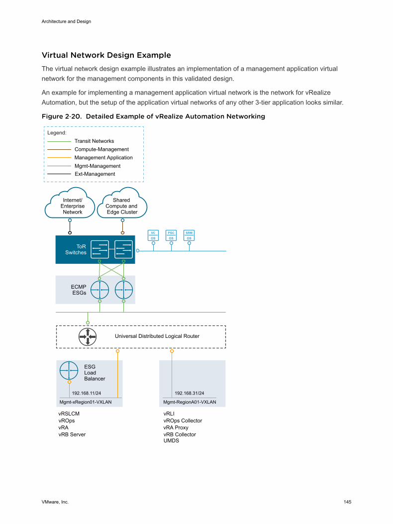
Virtual Network Design Example The virtual network design example illustrates an implementation of a management application virtualnetwork for the management components in this validated design.
An example for implementing a management application virtual network is the network for vRealizeAutomation, but the setup of the application virtual networks of any other 3-tier application looks similar.
Figure 2‑20. Detailed Example of vRealize Automation Networking
VC
OSPSC
OSSRM
OS
ECMPESGs
ToRSwitches
Internet/EnterpriseNetwork
Mgmt-Management
Compute-Management
Legend:
Shared Compute and Edge Cluster
192.168.11/24
Transit Networks
Management Application
vRAvROps
Universal Distributed Logical Router
ESGLoadBalancer
Mgmt-xRegion01-VXLAN
192.168.31/24
Mgmt-RegionA01-VXLAN
Ext-Management
vRB Server
vRLIvRSLCMvROps CollectorvRA Proxy
UMDSvRB Collector
Architecture and Design
VMware, Inc. 145
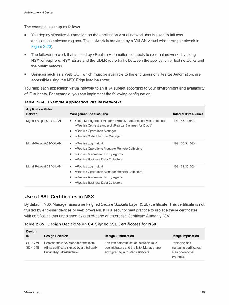
The example is set up as follows.
n You deploy vRealize Automation on the application virtual network that is used to fail overapplications between regions. This network is provided by a VXLAN virtual wire (orange network in Figure 2‑20).
n The failover network that is used by vRealize Automation connects to external networks by usingNSX for vSphere. NSX ESGs and the UDLR route traffic between the application virtual networks andthe public network.
n Services such as a Web GUI, which must be available to the end users of vRealize Automation, areaccessible using the NSX Edge load balancer.
You map each application virtual network to an IPv4 subnet according to your environment and availabilityof IP subnets. For example, you can implement the following configuration:
Table 2‑84. Example Application Virtual Networks
Application VirtualNetwork Management Applications Internal IPv4 Subnet
Mgmt-xRegion01-VXLAN n Cloud Management Platform (vRealize Automation with embeddedvRealize Orchestrator, and vRealize Business for Cloud)
n vRealize Operations Managern vRealize Suite Lifecycle Manager
192.168.11.0/24
Mgmt-RegionA01-VXLAN n vRealize Log Insightn vRealize Operations Manager Remote Collectorsn vRealize Automation Proxy Agentsn vRealize Business Data Collectors
192.168.31.0/24
Mgmt-RegionB01-VXLAN n vRealize Log Insightn vRealize Operations Manager Remote Collectorsn vRealize Automation Proxy Agentsn vRealize Business Data Collectors
192.168.32.0/24
Use of SSL Certificates in NSX By default, NSX Manager uses a self-signed Secure Sockets Layer (SSL) certificate. This certificate is nottrusted by end-user devices or web browsers. It is a security best practice to replace these certificateswith certificates that are signed by a third-party or enterprise Certificate Authority (CA).
Table 2‑85. Design Decisions on CA-Signed SSL Certificates for NSX
DesignID Design Decision Design Justification Design Implication
SDDC-VI-SDN-045
Replace the NSX Manager certificatewith a certificate signed by a third-partyPublic Key Infrastructure.
Ensures communication between NSXadministrators and the NSX Manager areencrypted by a trusted certificate.
Replacing andmanaging certificatesis an operationaloverhead.
Architecture and Design
VMware, Inc. 146
Shared Storage Design The shared storage design includes the design for vSAN and NFS storage storage.
Well-designed shared storage provides the basis for an SDDC and has the following benefits.
n Prevents unauthorized access to business data.
n Protects data from hardware and software failures.
n Protects data from malicious or accidental corruption.
Follow these guidelines when designing shared storage for your environment.
n Optimize the storage design to meet the diverse needs of applications, services, administrators, andusers.
n Strategically align business applications and the storage infrastructure to reduce costs, boostperformance, improve availability, provide security, and enhance functionality.
n Provide multiple tiers of storage to match application data access to application requirements.
n Design each tier of storage with different performance, capacity, and availability characteristics.Because not every application requires expensive, high-performance, highly available storage,designing different storage tiers reduces cost.
Shared Storage Platform You can choose between traditional storage, VMware vSphere Virtual Volumes, and VMware vSANstorage.
Storage Types
Traditional Storage Fibre Channel, NFS, and iSCSI are mature and viable options to supportvirtual machine needs.
VMware vSAN Storage vSAN is a software-based distributed storage platform that combines thecompute and storage resources of VMware ESXi hosts. When you designand size a vSAN cluster, hardware choices are more limited than fortraditional storage.
VMware vSphere VirtualVolumes
This design does not leverage VMware vSphere Virtual Volumes becausenot all storage arrays have the same vSphere Virtual Volume feature setsenabled.
Traditional Storage and vSAN Storage
Fibre Channel, NFS, and iSCSI are mature and viable options to support virtual machine needs.
Your decision to implement one technology or another can be based on performance and functionality,and on considerations like the following:
n The organization’s current in-house expertise and installation base
Architecture and Design
VMware, Inc. 147
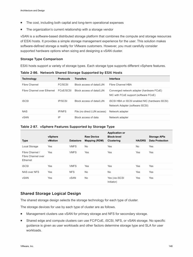
n The cost, including both capital and long-term operational expenses
n The organization’s current relationship with a storage vendor
vSAN is a software-based distributed storage platform that combines the compute and storage resourcesof ESXi hosts. It provides a simple storage management experience for the user. This solution makessoftware-defined storage a reality for VMware customers. However, you must carefully considersupported hardware options when sizing and designing a vSAN cluster.
Storage Type Comparison
ESXi hosts support a variety of storage types. Each storage type supports different vSphere features.
Table 2‑86. Network Shared Storage Supported by ESXi Hosts
Technology Protocols Transfers Interface
Fibre Channel FC/SCSI Block access of data/LUN Fibre Channel HBA
Fibre Channel over Ethernet FCoE/SCSI Block access of data/LUN Converged network adapter (hardware FCoE)
NIC with FCoE support (software FCoE)
iSCSI IP/SCSI Block access of data/LUN iSCSI HBA or iSCSI enabled NIC (hardware iSCSI)
Network Adapter (software iSCSI)
NAS IP/NFS File (no direct LUN access) Network adapter
vSAN IP Block access of data Network adapter
Table 2‑87. vSphere Features Supported by Storage Type
TypevSpherevMotion Datastore
Raw DeviceMapping (RDM)
Application orBlock-levelClustering HA/DRS
Storage APIsData Protection
Local Storage Yes VMFS No Yes No Yes
Fibre Channel /Fibre Channel overEthernet
Yes VMFS Yes Yes Yes Yes
iSCSI Yes VMFS Yes Yes Yes Yes
NAS over NFS Yes NFS No No Yes Yes
vSAN Yes vSAN No Yes (via iSCSIInitiator)
Yes Yes
Shared Storage Logical Design The shared storage design selects the storage technology for each type of cluster.
The storage devices for use by each type of cluster are as follows.
n Management clusters use vSAN for primary storage and NFS for secondary storage.
n Shared edge and compute clusters can use FC/FCoE, iSCSI, NFS, or vSAN storage. No specificguidance is given as user workloads and other factors determine storage type and SLA for userworkloads.
Architecture and Design
VMware, Inc. 148
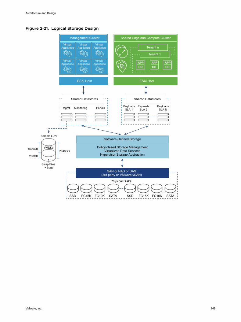
Figure 2‑21. Logical Storage Design
Virtual Appliance
Virtual Appliance
Virtual Appliance
Virtual Appliance
Virtual Appliance
Virtual Appliance APP
OSAPPOS
APPOS
Tenant n
Management Cluster Shared Edge and Compute Cluster
Tenant 1
ESXi Host ESXi Host
Shared Datastores
Mgmt Monitoring Portals
Shared Datastores
PayloadsSLA 1
PayloadsSLA 2
PayloadsSLA N
Software-Defined Storage
Policy-Based Storage ManagementVirtualized Data Services
Hypervisor Storage Abstraction
SAN or NAS or DAS(3rd party or VMware vSAN)
Physical Disks
SSD FC15K FC10K SATA SSD FC15K FC10K SATA
VMDKs
Swap Files + Logs
1500GB
200GB
2048GB
Sample LUN
Architecture and Design
VMware, Inc. 149
Table 2‑88. Design Decisions on Storage Type
Decision ID Design Decision Design JustificationDesignImplication
SDDC-VI-Storage-001
When using a single availability zone inthe management cluster, use vSANand NFS shared storage:n Use vSAN as the primary shared
storage platform.n Use NFS as the secondary shared
storage platform for themanagement cluster.
By using vSAN as the primary shared storage solution,you can take advantage of more cost-effective localstorage.
NFS is primarily for archiving and to maintain historicaldata. Using NFS provides large, low-cost volumes thatyou can flexibly expand regularly according to capacityneeds.
The use oftwo differentstoragetechnologiesincreases thecomplexityandoperationaloverhead.
You cannotconfiguremultipleavailabilityzones to usean NFS arrayin the eventan availabilityzone fails.
SDDC-VI-Storage-002
In all clusters, ensure that at least 20%of free space is always available on allnon-vSAN datastores.
If a datastore runs out of free space, applications andservices in the SDDC, including but not limited to theNSX Edge core network services, the provisioningportal, and backup, fail.
Monitoringand capacitymanagementmust beproactiveoperations.
Storage Tiering
Not all application workloads have the same storage requirements. Storage tiering allows for thesedifferences by creating multiple levels of storage with varying degrees of performance, reliability and cost,depending on the application workload needs.
Today’s enterprise-class storage arrays contain multiple drive types and protection mechanisms. Thestorage, server, and application administrators face challenges when selecting the correct storageconfiguration for each application being deployed in the environment. Virtualization can make thisproblem more challenging by consolidating many different application workloads onto a small number oflarge devices.
The most mission-critical data typically represents the smallest amount of data and offline data representsthe largest amount. Details differ for different organizations.
To determine the storage tier for application data, determine the storage characteristics of the applicationor service.
n I/O operations per second (IOPS) requirements
n Megabytes per second (MBps) requirements
n Capacity requirements
n Availability requirements
Architecture and Design
VMware, Inc. 150
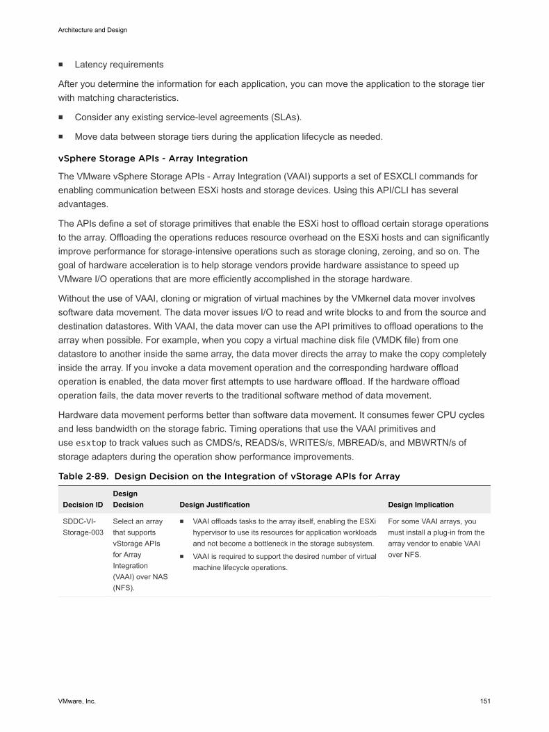
n Latency requirements
After you determine the information for each application, you can move the application to the storage tierwith matching characteristics.
n Consider any existing service-level agreements (SLAs).
n Move data between storage tiers during the application lifecycle as needed.
vSphere Storage APIs - Array Integration
The VMware vSphere Storage APIs - Array Integration (VAAI) supports a set of ESXCLI commands forenabling communication between ESXi hosts and storage devices. Using this API/CLI has severaladvantages.
The APIs define a set of storage primitives that enable the ESXi host to offload certain storage operationsto the array. Offloading the operations reduces resource overhead on the ESXi hosts and can significantlyimprove performance for storage-intensive operations such as storage cloning, zeroing, and so on. Thegoal of hardware acceleration is to help storage vendors provide hardware assistance to speed upVMware I/O operations that are more efficiently accomplished in the storage hardware.
Without the use of VAAI, cloning or migration of virtual machines by the VMkernel data mover involvessoftware data movement. The data mover issues I/O to read and write blocks to and from the source anddestination datastores. With VAAI, the data mover can use the API primitives to offload operations to thearray when possible. For example, when you copy a virtual machine disk file (VMDK file) from onedatastore to another inside the same array, the data mover directs the array to make the copy completelyinside the array. If you invoke a data movement operation and the corresponding hardware offloadoperation is enabled, the data mover first attempts to use hardware offload. If the hardware offloadoperation fails, the data mover reverts to the traditional software method of data movement.
Hardware data movement performs better than software data movement. It consumes fewer CPU cyclesand less bandwidth on the storage fabric. Timing operations that use the VAAI primitives anduse esxtop to track values such as CMDS/s, READS/s, WRITES/s, MBREAD/s, and MBWRTN/s ofstorage adapters during the operation show performance improvements.
Table 2‑89. Design Decision on the Integration of vStorage APIs for Array
Decision IDDesignDecision Design Justification Design Implication
SDDC-VI-Storage-003
Select an arraythat supportsvStorage APIsfor ArrayIntegration(VAAI) over NAS(NFS).
n VAAI offloads tasks to the array itself, enabling the ESXihypervisor to use its resources for application workloadsand not become a bottleneck in the storage subsystem.
n VAAI is required to support the desired number of virtualmachine lifecycle operations.
For some VAAI arrays, youmust install a plug-in from thearray vendor to enable VAAIover NFS.
Architecture and Design
VMware, Inc. 151
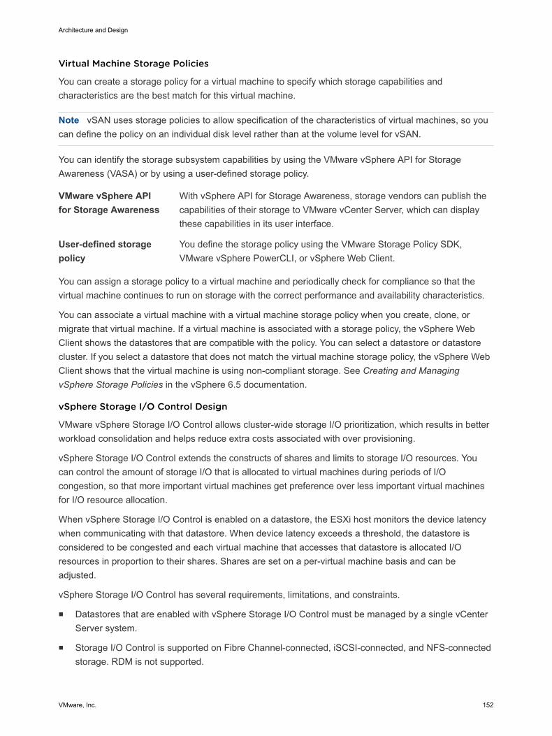
Virtual Machine Storage Policies
You can create a storage policy for a virtual machine to specify which storage capabilities andcharacteristics are the best match for this virtual machine.
Note vSAN uses storage policies to allow specification of the characteristics of virtual machines, so youcan define the policy on an individual disk level rather than at the volume level for vSAN.
You can identify the storage subsystem capabilities by using the VMware vSphere API for StorageAwareness (VASA) or by using a user-defined storage policy.
VMware vSphere APIfor Storage Awareness
With vSphere API for Storage Awareness, storage vendors can publish thecapabilities of their storage to VMware vCenter Server, which can displaythese capabilities in its user interface.
User-defined storagepolicy
You define the storage policy using the VMware Storage Policy SDK,VMware vSphere PowerCLI, or vSphere Web Client.
You can assign a storage policy to a virtual machine and periodically check for compliance so that thevirtual machine continues to run on storage with the correct performance and availability characteristics.
You can associate a virtual machine with a virtual machine storage policy when you create, clone, ormigrate that virtual machine. If a virtual machine is associated with a storage policy, the vSphere WebClient shows the datastores that are compatible with the policy. You can select a datastore or datastorecluster. If you select a datastore that does not match the virtual machine storage policy, the vSphere WebClient shows that the virtual machine is using non-compliant storage. See Creating and ManagingvSphere Storage Policies in the vSphere 6.5 documentation.
vSphere Storage I/O Control Design
VMware vSphere Storage I/O Control allows cluster-wide storage I/O prioritization, which results in betterworkload consolidation and helps reduce extra costs associated with over provisioning.
vSphere Storage I/O Control extends the constructs of shares and limits to storage I/O resources. Youcan control the amount of storage I/O that is allocated to virtual machines during periods of I/Ocongestion, so that more important virtual machines get preference over less important virtual machinesfor I/O resource allocation.
When vSphere Storage I/O Control is enabled on a datastore, the ESXi host monitors the device latencywhen communicating with that datastore. When device latency exceeds a threshold, the datastore isconsidered to be congested and each virtual machine that accesses that datastore is allocated I/Oresources in proportion to their shares. Shares are set on a per-virtual machine basis and can beadjusted.
vSphere Storage I/O Control has several requirements, limitations, and constraints.
n Datastores that are enabled with vSphere Storage I/O Control must be managed by a single vCenterServer system.
n Storage I/O Control is supported on Fibre Channel-connected, iSCSI-connected, and NFS-connectedstorage. RDM is not supported.
Architecture and Design
VMware, Inc. 152
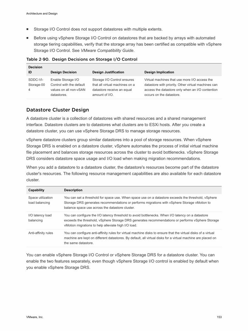
n Storage I/O Control does not support datastores with multiple extents.
n Before using vSphere Storage I/O Control on datastores that are backed by arrays with automatedstorage tiering capabilities, verify that the storage array has been certified as compatible with vSphereStorage I/O Control. See VMware Compatibility Guide.
Table 2‑90. Design Decisions on Storage I/O Control
DecisionID Design Decision Design Justification Design Implication
SDDC-VI-Storage-004
Enable Storage I/OControl with the defaultvalues on all non-vSANdatastores.
Storage I/O Control ensuresthat all virtual machines on adatastore receive an equalamount of I/O.
Virtual machines that use more I/O access thedatastore with priority. Other virtual machines canaccess the datastore only when an I/O contentionoccurs on the datastore.
Datastore Cluster Design A datastore cluster is a collection of datastores with shared resources and a shared managementinterface. Datastore clusters are to datastores what clusters are to ESXi hosts. After you create adatastore cluster, you can use vSphere Storage DRS to manage storage resources.
vSphere datastore clusters group similar datastores into a pool of storage resources. When vSphereStorage DRS is enabled on a datastore cluster, vSphere automates the process of initial virtual machinefile placement and balances storage resources across the cluster to avoid bottlenecks. vSphere StorageDRS considers datastore space usage and I/O load when making migration recommendations.
When you add a datastore to a datastore cluster, the datastore's resources become part of the datastorecluster's resources. The following resource management capabilities are also available for each datastorecluster.
Capability Description
Space utilizationload balancing
You can set a threshold for space use. When space use on a datastore exceeds the threshold, vSphereStorage DRS generates recommendations or performs migrations with vSphere Storage vMotion tobalance space use across the datastore cluster.
I/O latency loadbalancing
You can configure the I/O latency threshold to avoid bottlenecks. When I/O latency on a datastoreexceeds the threshold, vSphere Storage DRS generates recommendations or performs vSphere StoragevMotion migrations to help alleviate high I/O load.
Anti-affinity rules You can configure anti-affinity rules for virtual machine disks to ensure that the virtual disks of a virtualmachine are kept on different datastores. By default, all virtual disks for a virtual machine are placed onthe same datastore.
You can enable vSphere Storage I/O Control or vSphere Storage DRS for a datastore cluster. You canenable the two features separately, even though vSphere Storage I/O control is enabled by default whenyou enable vSphere Storage DRS.
Architecture and Design
VMware, Inc. 153
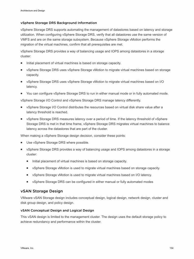
vSphere Storage DRS Background Information
vSphere Storage DRS supports automating the management of datastores based on latency and storageutilization. When configuring vSphere Storage DRS, verify that all datastores use the same version ofVMFS and are on the same storage subsystem. Because vSphere Storage vMotion performs themigration of the virtual machines, confirm that all prerequisites are met.
vSphere Storage DRS provides a way of balancing usage and IOPS among datastores in a storagecluster:
n Initial placement of virtual machines is based on storage capacity.
n vSphere Storage DRS uses vSphere Storage vMotion to migrate virtual machines based on storagecapacity.
n vSphere Storage DRS uses vSphere Storage vMotion to migrate virtual machines based on I/Olatency.
n You can configure vSphere Storage DRS to run in either manual mode or in fully automated mode.
vSphere Storage I/O Control and vSphere Storage DRS manage latency differently.
n vSphere Storage I/O Control distributes the resources based on virtual disk share value after alatency threshold is reached.
n vSphere Storage DRS measures latency over a period of time. If the latency threshold of vSphereStorage DRS is met in that time frame, vSphere Storage DRS migrates virtual machines to balancelatency across the datastores that are part of the cluster.
When making a vSphere Storage design decision, consider these points:
n Use vSphere Storage DRS where possible.
n vSphere Storage DRS provides a way of balancing usage and IOPS among datastores in a storagecluster:
n Initial placement of virtual machines is based on storage capacity.
n vSphere Storage vMotion is used to migrate virtual machines based on storage capacity.
n vSphere Storage vMotion is used to migrate virtual machines based on I/O latency.
n vSphere Storage DRS can be configured in either manual or fully automated modes
vSAN Storage Design VMware vSAN Storage design includes conceptual design, logical design, network design, cluster anddisk group design, and policy design.
vSAN Conceptual Design and Logical Design
This vSAN design is limited to the management cluster. The design uses the default storage policy toachieve redundancy and performance within the cluster.
Architecture and Design
VMware, Inc. 154
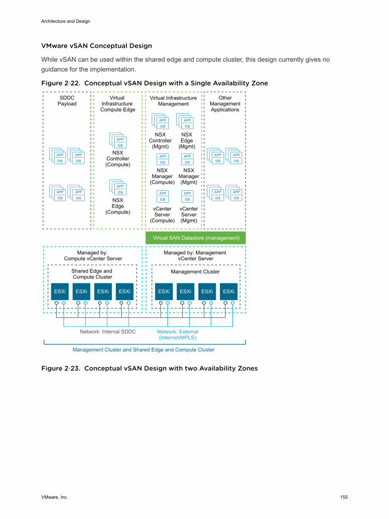
VMware vSAN Conceptual Design
While vSAN can be used within the shared edge and compute cluster, this design currently gives noguidance for the implementation.
Figure 2‑22. Conceptual vSAN Design with a Single Availability Zone
APP
OSAPP
OS
APP
OSAPP
OS
APP
OSAPP
OS
APP
OSAPP
OS
APP
OS
APP
OS
APP
OSAPP
OS
APP
OSAPP
OS
APP
OSAPP
OS
ESXi ESXi
Virtual InfrastructureManagement
NSXController
(Mgmt)
OtherManagementApplications
NSXEdge
(Mgmt)
NSXManager(Mgmt)
NSXManager
(Compute)
NSXEdge
(Compute)
NSXController(Compute)
ESXi ESXi ESXi ESXi ESXi ESXi
SDDCPayload
Virtual Infrastructure Compute Edge
Virtual SAN Datastore (management)
Shared Edge and Compute Cluster
Management Cluster
Managed by: Compute vCenter Server
Managed by: Management vCenter Server
Network: External(Internet/MPLS)
Network: Internal SDDC
Management Cluster and Shared Edge and Compute Cluster
vCenterServer(Mgmt)
vCenterServer
(Compute)
Figure 2‑23. Conceptual vSAN Design with two Availability Zones
Architecture and Design
VMware, Inc. 155
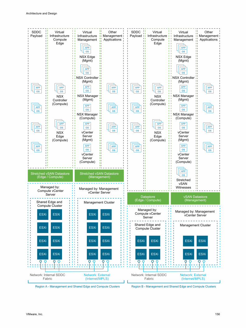
APP
OS
APP
OS
APP
OS
APP
OSAPP
OS
APP
OS
APP
OS
APP
OS
ESXi
APP
OS
APP
OS
APP
OS
APP
OS
APP
OS
APP
OS
APP
OS
APP
OS
APP
OS
APP
OS
APP
OS
APP
OSAPP
OS
APP
OS
APP
OS
APP
OSAPP
OS
APP
OS
APP
OS
APP
OS
APP
OS
APP
OS
APP
OS
APP
OS
APP
OS
VirtualInfrastructureManagement
NSX Controller(Mgmt)
OtherManagementApplications
NSX Edge(Mgmt)
NSX Manager(Mgmt)
NSX Manager(Compute)
NSXEdge
(Compute)
NSXController(Compute)
ESXi
ESXi ESXi
SDDCPayload
Virtual Infrastructure
ComputeEdge
Stretched vSAN Datastore(Edge / Compute)
Stretched vSAN Datastore(Management)
Shared Edge and Compute Cluster
Management Cluster
Managed by: Compute vCenter
Server
Managed by: Management vCenter Server
Network: External(Internet/MPLS)
Network: Internal SDDCFabric
Region A - Management and Shared Edge and Compute Clusters
vCenterServer(Mgmt)
vCenterServer
(Compute)
ESXiESXi
ESXi ESXi
ESXiESXi
ESXi ESXi
ESXiESXi
ESXi ESXi
ESXi
VirtualInfrastructureManagement
NSX Controller(Mgmt)
OtherManagementApplications
NSX Edge(Mgmt)
NSX Manager(Mgmt)
NSX Manager(Compute)
NSXEdge
(Compute)
NSXController(Compute)
ESXi
ESXi ESXi
SDDCPayload
Virtual Infrastructure
ComputeEdge
Datastore(Edge / Compute)
vSAN Datastore(Management)
Shared Edge and Compute Cluster
Management Cluster
Managed by: Compute vCenter
Server
Managed by: Management vCenter Server
Network: External(Internet/MPLS)
Network: Internal SDDCFabric
Region B - Management and Shared Edge and Compute Clusters
vCenterServer(Mgmt)
vCenterServer
(Compute)
ESXiESXi
ESXi ESXi
StretchedvSAN
Witnesses
Architecture and Design
VMware, Inc. 156
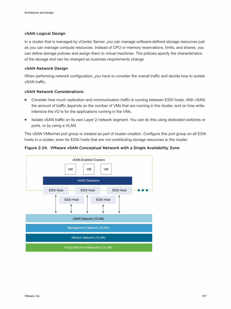
vSAN Logical Design
In a cluster that is managed by vCenter Server, you can manage software-defined storage resources justas you can manage compute resources. Instead of CPU or memory reservations, limits, and shares, youcan define storage policies and assign them to virtual machines. The policies specify the characteristicsof the storage and can be changed as business requirements change.
vSAN Network Design
When performing network configuration, you have to consider the overall traffic and decide how to isolatevSAN traffic.
vSAN Network Considerations
n Consider how much replication and communication traffic is running between ESXi hosts. With vSAN,the amount of traffic depends on the number of VMs that are running in the cluster, and on how write-intensive the I/O is for the applications running in the VMs.
n Isolate vSAN traffic on its own Layer 2 network segment. You can do this using dedicated switches orports, or by using a VLAN.
The vSAN VMkernel port group is created as part of cluster creation. Configure this port group on all ESXihosts in a cluster, even for ESXi hosts that are not contributing storage resources to the cluster.
Figure 2‑24. VMware vSAN Conceptual Network with a Single Availability Zone
VM VM VM
ESXi Host ESXi Host ESXi Host
ESXi Host ESXi Host
vSAN Datastore
vSAN-Enabled Clusters
vSAN Network (VLAN)
Management Network (VLAN)
vMotion Network (VLAN)
Virtual Machine Network(s) (VLAN)
Architecture and Design
VMware, Inc. 157
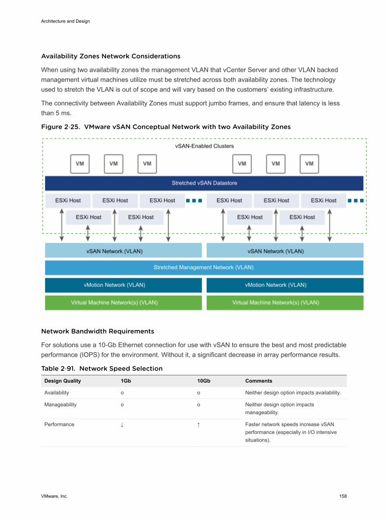
Availability Zones Network Considerations
When using two availability zones the management VLAN that vCenter Server and other VLAN backedmanagement virtual machines utilize must be stretched across both availability zones. The technologyused to stretch the VLAN is out of scope and will vary based on the customers’ existing infrastructure.
The connectivity between Availability Zones must support jumbo frames, and ensure that latency is lessthan 5 ms.
Figure 2‑25. VMware vSAN Conceptual Network with two Availability Zones
Network Bandwidth Requirements
For solutions use a 10-Gb Ethernet connection for use with vSAN to ensure the best and most predictableperformance (IOPS) for the environment. Without it, a significant decrease in array performance results.
Table 2‑91. Network Speed Selection
Design Quality 1Gb 10Gb Comments
Availability o o Neither design option impacts availability.
Manageability o o Neither design option impactsmanageability.
Performance ↓ ↑ Faster network speeds increase vSANperformance (especially in I/O intensivesituations).
Architecture and Design
VMware, Inc. 158
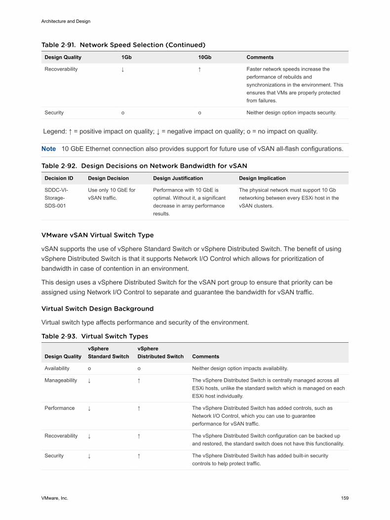
Table 2‑91. Network Speed Selection (Continued)
Design Quality 1Gb 10Gb Comments
Recoverability ↓ ↑ Faster network speeds increase theperformance of rebuilds andsynchronizations in the environment. Thisensures that VMs are properly protectedfrom failures.
Security o o Neither design option impacts security.
Legend: ↑ = positive impact on quality; ↓ = negative impact on quality; o = no impact on quality.
Note 10 GbE Ethernet connection also provides support for future use of vSAN all-flash configurations.
Table 2‑92. Design Decisions on Network Bandwidth for vSAN
Decision ID Design Decision Design Justification Design Implication
SDDC-VI-Storage-SDS-001
Use only 10 GbE forvSAN traffic.
Performance with 10 GbE isoptimal. Without it, a significantdecrease in array performanceresults.
The physical network must support 10 Gbnetworking between every ESXi host in thevSAN clusters.
VMware vSAN Virtual Switch Type
vSAN supports the use of vSphere Standard Switch or vSphere Distributed Switch. The benefit of usingvSphere Distributed Switch is that it supports Network I/O Control which allows for prioritization ofbandwidth in case of contention in an environment.
This design uses a vSphere Distributed Switch for the vSAN port group to ensure that priority can beassigned using Network I/O Control to separate and guarantee the bandwidth for vSAN traffic.
Virtual Switch Design Background
Virtual switch type affects performance and security of the environment.
Table 2‑93. Virtual Switch Types
Design QualityvSphereStandard Switch
vSphereDistributed Switch Comments
Availability o o Neither design option impacts availability.
Manageability ↓ ↑ The vSphere Distributed Switch is centrally managed across allESXi hosts, unlike the standard switch which is managed on eachESXi host individually.
Performance ↓ ↑ The vSphere Distributed Switch has added controls, such asNetwork I/O Control, which you can use to guaranteeperformance for vSAN traffic.
Recoverability ↓ ↑ The vSphere Distributed Switch configuration can be backed upand restored, the standard switch does not have this functionality.
Security ↓ ↑ The vSphere Distributed Switch has added built-in securitycontrols to help protect traffic.
Architecture and Design
VMware, Inc. 159
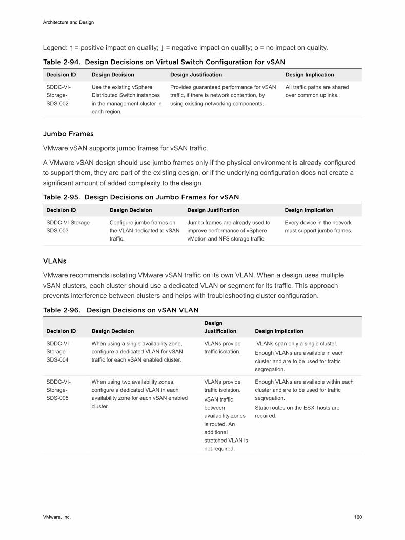
Legend: ↑ = positive impact on quality; ↓ = negative impact on quality; o = no impact on quality.
Table 2‑94. Design Decisions on Virtual Switch Configuration for vSAN
Decision ID Design Decision Design Justification Design Implication
SDDC-VI-Storage-SDS-002
Use the existing vSphereDistributed Switch instancesin the management cluster ineach region.
Provides guaranteed performance for vSANtraffic, if there is network contention, byusing existing networking components.
All traffic paths are sharedover common uplinks.
Jumbo Frames
VMware vSAN supports jumbo frames for vSAN traffic.
A VMware vSAN design should use jumbo frames only if the physical environment is already configuredto support them, they are part of the existing design, or if the underlying configuration does not create asignificant amount of added complexity to the design.
Table 2‑95. Design Decisions on Jumbo Frames for vSAN
Decision ID Design Decision Design Justification Design Implication
SDDC-VI-Storage-SDS-003
Configure jumbo frames onthe VLAN dedicated to vSANtraffic.
Jumbo frames are already used toimprove performance of vSpherevMotion and NFS storage traffic.
Every device in the networkmust support jumbo frames.
VLANs
VMware recommends isolating VMware vSAN traffic on its own VLAN. When a design uses multiplevSAN clusters, each cluster should use a dedicated VLAN or segment for its traffic. This approachprevents interference between clusters and helps with troubleshooting cluster configuration.
Table 2‑96. Design Decisions on vSAN VLAN
Decision ID Design DecisionDesignJustification Design Implication
SDDC-VI-Storage-SDS-004
When using a single availability zone,configure a dedicated VLAN for vSANtraffic for each vSAN enabled cluster.
VLANs providetraffic isolation.
VLANs span only a single cluster.
Enough VLANs are available in eachcluster and are to be used for trafficsegregation.
SDDC-VI-Storage-SDS-005
When using two availability zones,configure a dedicated VLAN in eachavailability zone for each vSAN enabledcluster.
VLANs providetraffic isolation.
vSAN trafficbetweenavailability zonesis routed. Anadditionalstretched VLAN isnot required.
Enough VLANs are available within eachcluster and are to be used for trafficsegregation.
Static routes on the ESXi hosts arerequired.
Architecture and Design
VMware, Inc. 160
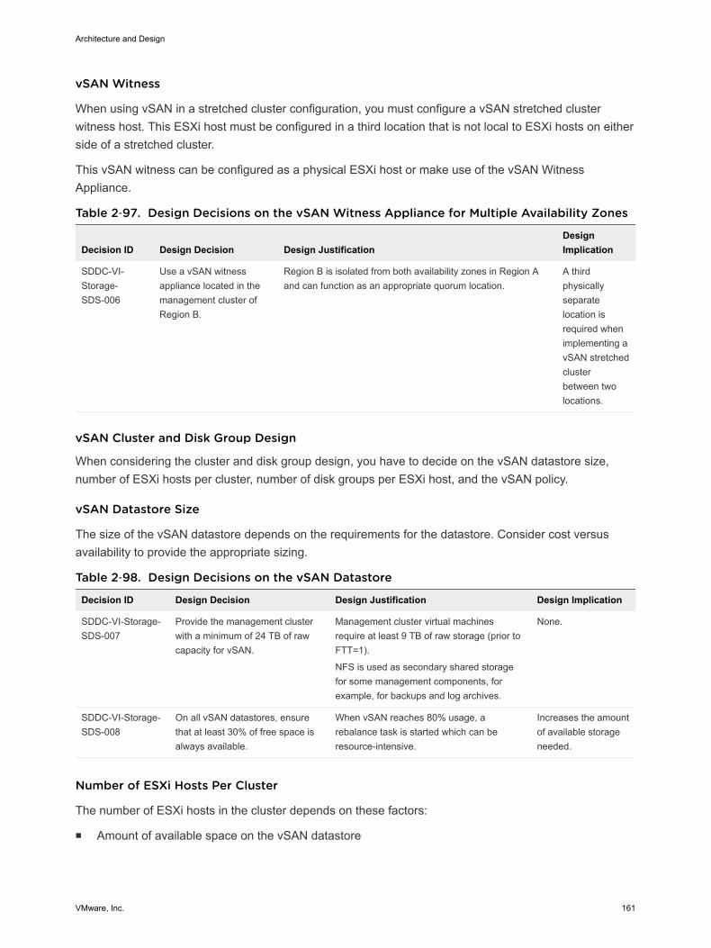
vSAN Witness
When using vSAN in a stretched cluster configuration, you must configure a vSAN stretched clusterwitness host. This ESXi host must be configured in a third location that is not local to ESXi hosts on eitherside of a stretched cluster.
This vSAN witness can be configured as a physical ESXi host or make use of the vSAN WitnessAppliance.
Table 2‑97. Design Decisions on the vSAN Witness Appliance for Multiple Availability Zones
Decision ID Design Decision Design JustificationDesignImplication
SDDC-VI-Storage-SDS-006
Use a vSAN witnessappliance located in themanagement cluster ofRegion B.
Region B is isolated from both availability zones in Region Aand can function as an appropriate quorum location.
A thirdphysicallyseparatelocation isrequired whenimplementing avSAN stretchedclusterbetween twolocations.
vSAN Cluster and Disk Group Design
When considering the cluster and disk group design, you have to decide on the vSAN datastore size,number of ESXi hosts per cluster, number of disk groups per ESXi host, and the vSAN policy.
vSAN Datastore Size
The size of the vSAN datastore depends on the requirements for the datastore. Consider cost versusavailability to provide the appropriate sizing.
Table 2‑98. Design Decisions on the vSAN Datastore
Decision ID Design Decision Design Justification Design Implication
SDDC-VI-Storage-SDS-007
Provide the management clusterwith a minimum of 24 TB of rawcapacity for vSAN.
Management cluster virtual machinesrequire at least 9 TB of raw storage (prior toFTT=1).
NFS is used as secondary shared storagefor some management components, forexample, for backups and log archives.
None.
SDDC-VI-Storage-SDS-008
On all vSAN datastores, ensurethat at least 30% of free space isalways available.
When vSAN reaches 80% usage, arebalance task is started which can beresource-intensive.
Increases the amountof available storageneeded.
Number of ESXi Hosts Per Cluster
The number of ESXi hosts in the cluster depends on these factors:
n Amount of available space on the vSAN datastore
Architecture and Design
VMware, Inc. 161
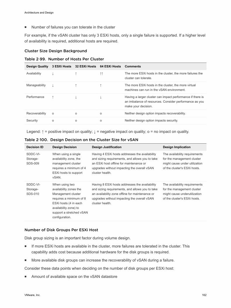
n Number of failures you can tolerate in the cluster
For example, if the vSAN cluster has only 3 ESXi hosts, only a single failure is supported. If a higher levelof availability is required, additional hosts are required.
Cluster Size Design Background
Table 2‑99. Number of Hosts Per Cluster
Design Quality 3 ESXi Hosts 32 ESXi Hosts 64 ESXi Hosts Comments
Availability ↓ ↑ ↑↑ The more ESXi hosts in the cluster, the more failures thecluster can tolerate.
Manageability ↓ ↑ ↑ The more ESXi hosts in the cluster, the more virtualmachines can run in the vSAN environment.
Performance ↑ ↓ ↓ Having a larger cluster can impact performance if there isan imbalance of resources. Consider performance as youmake your decision.
Recoverability o o o Neither design option impacts recoverability.
Security o o o Neither design option impacts security.
Legend: ↑ = positive impact on quality; ↓ = negative impact on quality; o = no impact on quality.
Table 2‑100. Design Decision on the Cluster Size for vSAN
Decision ID Design Decision Design Justification Design Implication
SDDC-VI-Storage-SDS-009
When using a singleavailability zone, themanagement clusterrequires a minimum of 4ESXi hosts to supportvSAN.
Having 4 ESXi hosts addresses the availabilityand sizing requirements, and allows you to takean ESXi host offline for maintenance orupgrades without impacting the overall vSANcluster health.
The availability requirementsfor the management clustermight cause under utilizationof the cluster's ESXi hosts.
SDDC-VI-Storage-SDS-010
When using twoavailability zones theManagement clusterrequires a minimum of 8ESXi hosts (4 in eachavailability zone) tosupport a stretched vSANconfiguration.
Having 8 ESXi hosts addresses the availabilityand sizing requirements, and allows you to takean availability zone offline for maintenance orupgrades without impacting the overall vSANcluster health.
The availability requirementsfor the management clustermight cause underutilizationof the cluster's ESXi hosts.
Number of Disk Groups Per ESXi Host
Disk group sizing is an important factor during volume design.
n If more ESXi hosts are available in the cluster, more failures are tolerated in the cluster. Thiscapability adds cost because additional hardware for the disk groups is required.
n More available disk groups can increase the recoverability of vSAN during a failure.
Consider these data points when deciding on the number of disk groups per ESXi host:
n Amount of available space on the vSAN datastore
Architecture and Design
VMware, Inc. 162
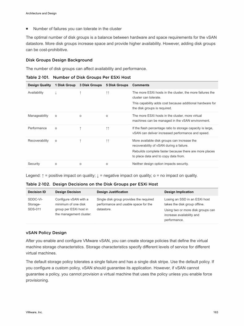
n Number of failures you can tolerate in the cluster
The optimal number of disk groups is a balance between hardware and space requirements for the vSANdatastore. More disk groups increase space and provide higher availability. However, adding disk groupscan be cost-prohibitive.
Disk Groups Design Background
The number of disk groups can affect availability and performance.
Table 2‑101. Number of Disk Groups Per ESXi Host
Design Quality 1 Disk Group 3 Disk Groups 5 Disk Groups Comments
Availability ↓ ↑ ↑↑ The more ESXi hosts in the cluster, the more failures thecluster can tolerate.
This capability adds cost because additional hardware forthe disk groups is required.
Manageability o o o The more ESXi hosts in the cluster, more virtualmachines can be managed in the vSAN environment.
Performance o ↑ ↑↑ If the flash percentage ratio to storage capacity is large,vSAN can deliver increased performance and speed.
Recoverability o ↑ ↑↑ More available disk groups can increase therecoverability of vSAN during a failure.
Rebuilds complete faster because there are more placesto place data and to copy data from.
Security o o o Neither design option impacts security.
Legend: ↑ = positive impact on quality; ↓ = negative impact on quality; o = no impact on quality.
Table 2‑102. Design Decisions on the Disk Groups per ESXi Host
Decision ID Design Decision Design Justification Design Implication
SDDC-VI-Storage-SDS-011
Configure vSAN with aminimum of one diskgroup per ESXi host inthe management cluster.
Single disk group provides the requiredperformance and usable space for thedatastore.
Losing an SSD in an ESXi hosttakes the disk group offline.
Using two or more disk groups canincrease availability andperformance.
vSAN Policy Design
After you enable and configure VMware vSAN, you can create storage policies that define the virtualmachine storage characteristics. Storage characteristics specify different levels of service for differentvirtual machines.
The default storage policy tolerates a single failure and has a single disk stripe. Use the default policy. Ifyou configure a custom policy, vSAN should guarantee its application. However, if vSAN cannotguarantee a policy, you cannot provision a virtual machine that uses the policy unless you enable forceprovisioning.
Architecture and Design
VMware, Inc. 163
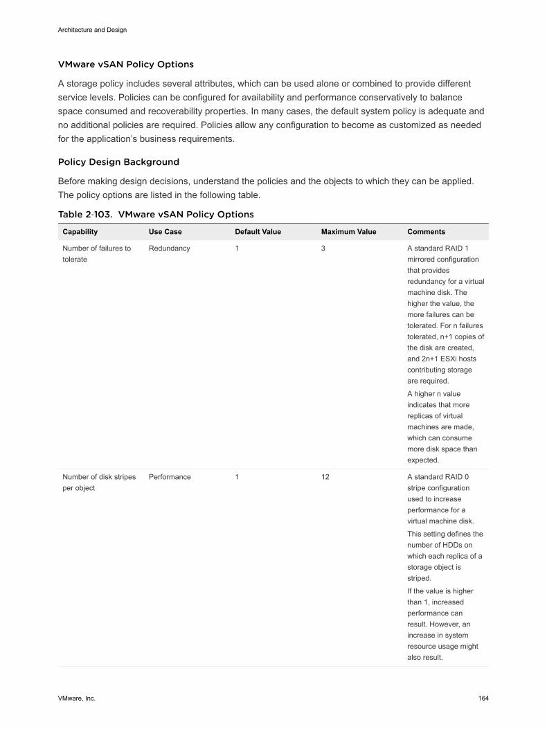
VMware vSAN Policy Options
A storage policy includes several attributes, which can be used alone or combined to provide differentservice levels. Policies can be configured for availability and performance conservatively to balancespace consumed and recoverability properties. In many cases, the default system policy is adequate andno additional policies are required. Policies allow any configuration to become as customized as neededfor the application’s business requirements.
Policy Design Background
Before making design decisions, understand the policies and the objects to which they can be applied.The policy options are listed in the following table.
Table 2‑103. VMware vSAN Policy Options
Capability Use Case Default Value Maximum Value Comments
Number of failures totolerate
Redundancy 1 3 A standard RAID 1mirrored configurationthat providesredundancy for a virtualmachine disk. Thehigher the value, themore failures can betolerated. For n failurestolerated, n+1 copies ofthe disk are created,and 2n+1 ESXi hostscontributing storageare required.
A higher n valueindicates that morereplicas of virtualmachines are made,which can consumemore disk space thanexpected.
Number of disk stripesper object
Performance 1 12 A standard RAID 0stripe configurationused to increaseperformance for avirtual machine disk.
This setting defines thenumber of HDDs onwhich each replica of astorage object isstriped.
If the value is higherthan 1, increasedperformance canresult. However, anincrease in systemresource usage mightalso result.
Architecture and Design
VMware, Inc. 164
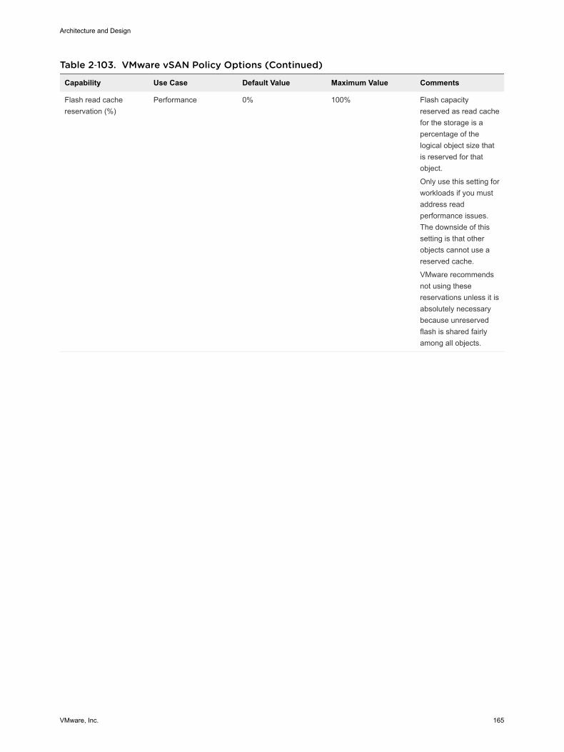
Table 2‑103. VMware vSAN Policy Options (Continued)
Capability Use Case Default Value Maximum Value Comments
Flash read cachereservation (%)
Performance 0% 100% Flash capacityreserved as read cachefor the storage is apercentage of thelogical object size thatis reserved for thatobject.
Only use this setting forworkloads if you mustaddress readperformance issues.The downside of thissetting is that otherobjects cannot use areserved cache.
VMware recommendsnot using thesereservations unless it isabsolutely necessarybecause unreservedflash is shared fairlyamong all objects.
Architecture and Design
VMware, Inc. 165

Table 2‑103. VMware vSAN Policy Options (Continued)
Capability Use Case Default Value Maximum Value Comments
Object spacereservation (%)
Thick provisioning 0% 100% The percentage of thestorage object that willbe thick provisionedupon VM creation. Theremainder of thestorage will be thinprovisioned.
This setting is useful ifa predictable amountof storage will alwaysbe filled by an object,cutting back onrepeatable disk growthoperations for all butnew or non-predictablestorage use.
Force provisioning Override policy No - Force provisioningforces provisioning tooccur even if thecurrently availablecluster resourcescannot satisfy thecurrent policy.
Force provisioning isuseful in case of aplanned expansion ofthe vSAN cluster,during whichprovisioning of VMsmust continue. VMwarevSAN automaticallytries to bring the objectinto compliance asresources becomeavailable.
By default, policies are configured based on application requirements. However, they are applieddifferently depending on the object.
Table 2‑104. Object Policy Defaults
Object Policy Comments
Virtual machine namespace Failures-to-Tolerate: 1 Configurable. Changes are not recommended.
Swap Failures-to-Tolerate: 1 Configurable. Changes are not recommended.
Architecture and Design
VMware, Inc. 166
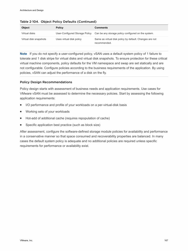
Table 2‑104. Object Policy Defaults (Continued)
Object Policy Comments
Virtual disks User-Configured Storage Policy Can be any storage policy configured on the system.
Virtual disk snapshots Uses virtual disk policy Same as virtual disk policy by default. Changes are notrecommended.
Note If you do not specify a user-configured policy, vSAN uses a default system policy of 1 failure totolerate and 1 disk stripe for virtual disks and virtual disk snapshots. To ensure protection for these criticalvirtual machine components, policy defaults for the VM namespace and swap are set statically and arenot configurable. Configure policies according to the business requirements of the application. By usingpolicies, vSAN can adjust the performance of a disk on the fly.
Policy Design Recommendations
Policy design starts with assessment of business needs and application requirements. Use cases forVMware vSAN must be assessed to determine the necessary policies. Start by assessing the followingapplication requirements:
n I/O performance and profile of your workloads on a per-virtual-disk basis
n Working sets of your workloads
n Hot-add of additional cache (requires repopulation of cache)
n Specific application best practice (such as block size)
After assessment, configure the software-defined storage module policies for availability and performancein a conservative manner so that space consumed and recoverability properties are balanced. In manycases the default system policy is adequate and no additional policies are required unless specificrequirements for performance or availability exist.
Architecture and Design
VMware, Inc. 167
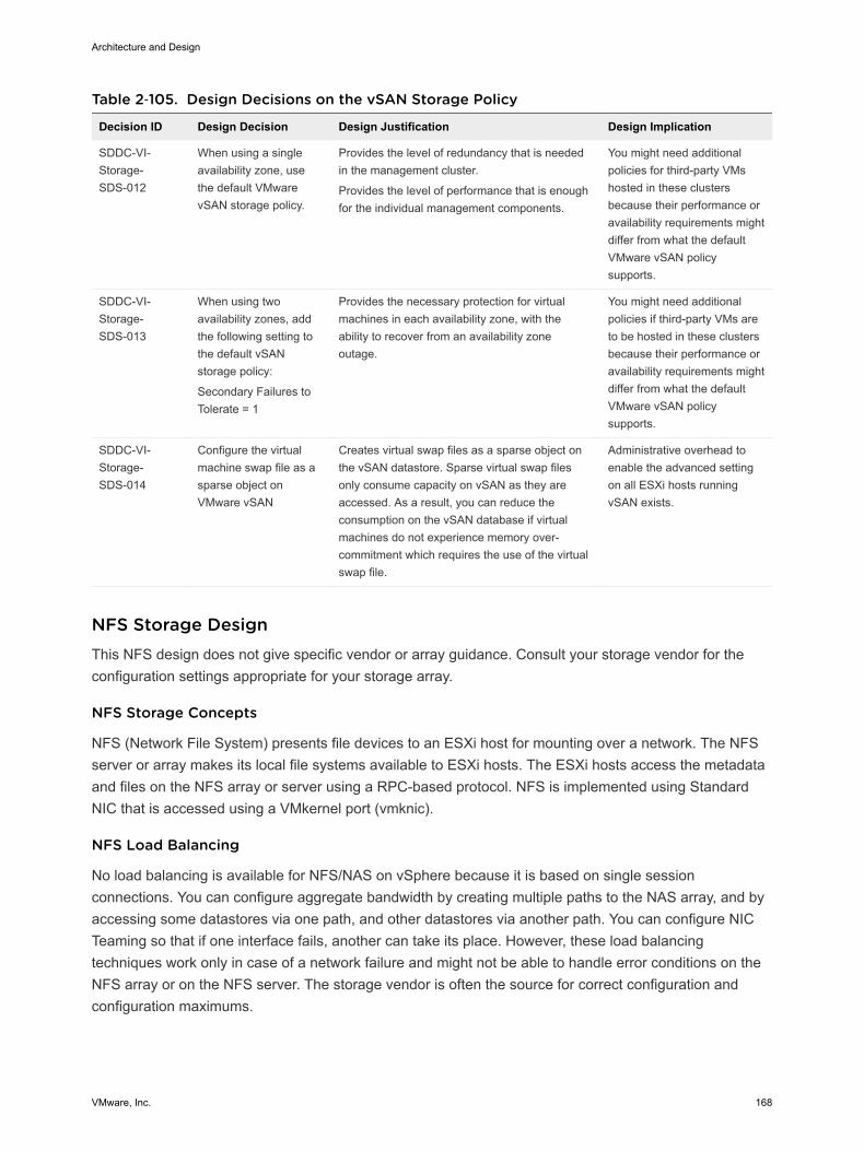
Table 2‑105. Design Decisions on the vSAN Storage Policy
Decision ID Design Decision Design Justification Design Implication
SDDC-VI-Storage-SDS-012
When using a singleavailability zone, usethe default VMwarevSAN storage policy.
Provides the level of redundancy that is neededin the management cluster.
Provides the level of performance that is enoughfor the individual management components.
You might need additionalpolicies for third-party VMshosted in these clustersbecause their performance oravailability requirements mightdiffer from what the defaultVMware vSAN policysupports.
SDDC-VI-Storage-SDS-013
When using twoavailability zones, addthe following setting tothe default vSANstorage policy:
Secondary Failures toTolerate = 1
Provides the necessary protection for virtualmachines in each availability zone, with theability to recover from an availability zoneoutage.
You might need additionalpolicies if third-party VMs areto be hosted in these clustersbecause their performance oravailability requirements mightdiffer from what the defaultVMware vSAN policysupports.
SDDC-VI-Storage-SDS-014
Configure the virtualmachine swap file as asparse object onVMware vSAN
Creates virtual swap files as a sparse object onthe vSAN datastore. Sparse virtual swap filesonly consume capacity on vSAN as they areaccessed. As a result, you can reduce theconsumption on the vSAN database if virtualmachines do not experience memory over-commitment which requires the use of the virtualswap file.
Administrative overhead toenable the advanced settingon all ESXi hosts runningvSAN exists.
NFS Storage DesignThis NFS design does not give specific vendor or array guidance. Consult your storage vendor for theconfiguration settings appropriate for your storage array.
NFS Storage Concepts
NFS (Network File System) presents file devices to an ESXi host for mounting over a network. The NFSserver or array makes its local file systems available to ESXi hosts. The ESXi hosts access the metadataand files on the NFS array or server using a RPC-based protocol. NFS is implemented using StandardNIC that is accessed using a VMkernel port (vmknic).
NFS Load Balancing
No load balancing is available for NFS/NAS on vSphere because it is based on single sessionconnections. You can configure aggregate bandwidth by creating multiple paths to the NAS array, and byaccessing some datastores via one path, and other datastores via another path. You can configure NICTeaming so that if one interface fails, another can take its place. However, these load balancingtechniques work only in case of a network failure and might not be able to handle error conditions on theNFS array or on the NFS server. The storage vendor is often the source for correct configuration andconfiguration maximums.
Architecture and Design
VMware, Inc. 168
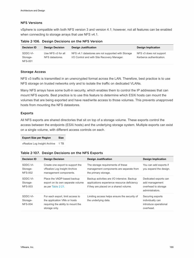
NFS Versions
vSphere is compatible with both NFS version 3 and version 4.1; however, not all features can be enabledwhen connecting to storage arrays that use NFS v4.1.
Table 2‑106. Design Decisions on the NFS Version
Decision ID Design Decision Design Justification Design Implication
SDDC-VI-Storage-NFS-001
Use NFS v3 for allNFS datastores.
NFS v4.1 datastores are not supported with StorageI/O Control and with Site Recovery Manager.
NFS v3 does not supportKerberos authentication.
Storage Access
NFS v3 traffic is transmitted in an unencrypted format across the LAN. Therefore, best practice is to useNFS storage on trusted networks only and to isolate the traffic on dedicated VLANs.
Many NFS arrays have some built-in security, which enables them to control the IP addresses that canmount NFS exports. Best practice is to use this feature to determine which ESXi hosts can mount thevolumes that are being exported and have read/write access to those volumes. This prevents unapprovedhosts from mounting the NFS datastores.
Exports
All NFS exports are shared directories that sit on top of a storage volume. These exports control theaccess between the endpoints (ESXi hosts) and the underlying storage system. Multiple exports can existon a single volume, with different access controls on each.
Export Size per Region Size
vRealize Log Insight Archive 1 TB
Table 2‑107. Design Decisions on the NFS Exports
Decision ID Design Decision Design Justification Design Implication
SDDC-VI-Storage-NFS-002
Create one export to support thevRealize Log Insight Archivemanagement components.
The storage requirements of thesemanagement components are separate fromthe primary storage.
You can add exports ifyou expand the design.
SDDC-VI-Storage-NFS-003
Place the VADP-based backupexport on its own separate volumeas per Table 2‑21.
Backup activities are I/O intensive. Backupapplications experience resource deficiencyif they are placed on a shared volume.
Dedicated exports canadd managementoverhead to storageadministrators.
SDDC-VI-Storage-NFS-004
For each export, limit access tothe application VMs or hostsrequiring the ability to mount thestorage only.
Limiting access helps ensure the security ofthe underlying data.
Securing exportsindividually canintroduce operationaloverhead.
Architecture and Design
VMware, Inc. 169
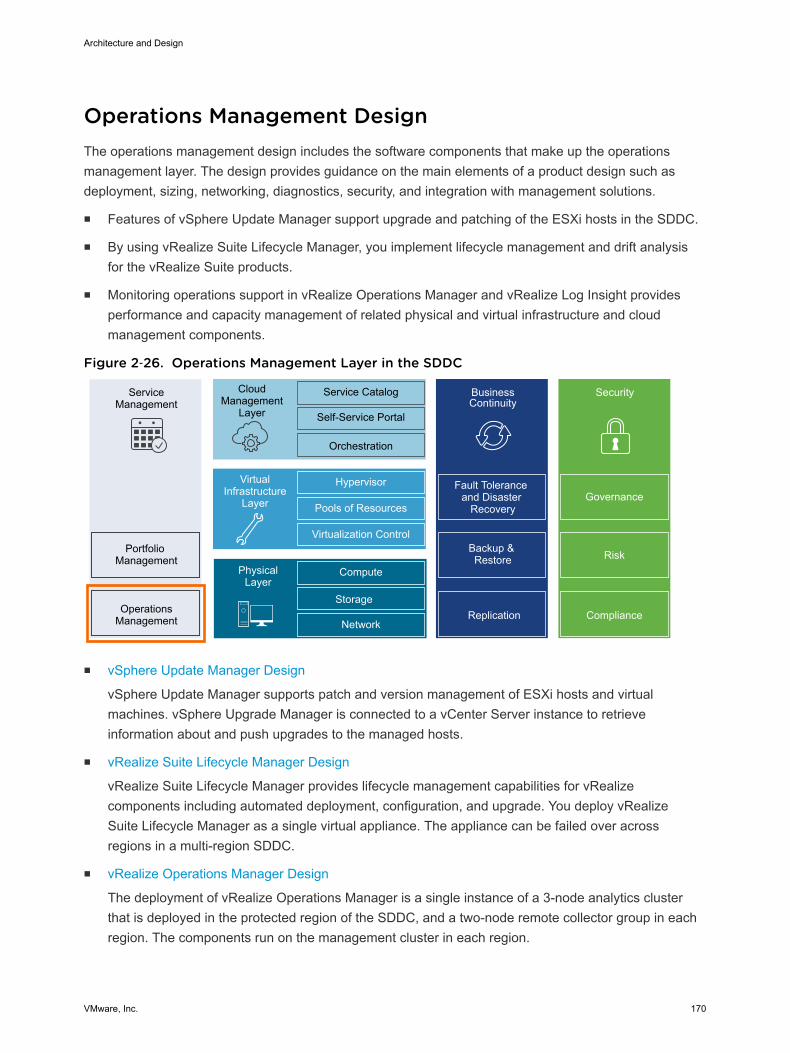
Operations Management Design The operations management design includes the software components that make up the operationsmanagement layer. The design provides guidance on the main elements of a product design such asdeployment, sizing, networking, diagnostics, security, and integration with management solutions.
n Features of vSphere Update Manager support upgrade and patching of the ESXi hosts in the SDDC.
n By using vRealize Suite Lifecycle Manager, you implement lifecycle management and drift analysisfor the vRealize Suite products.
n Monitoring operations support in vRealize Operations Manager and vRealize Log Insight providesperformance and capacity management of related physical and virtual infrastructure and cloudmanagement components.
Figure 2‑26. Operations Management Layer in the SDDC
ServiceManagement
Portfolio Management
OperationsManagement
CloudManagement
Layer
Service Catalog
Self-Service Portal
Orchestration
BusinessContinuity
Fault Tolerance and Disaster
Recovery
Backup & Restore
Hypervisor
Pools of Resources
Virtualization Control
VirtualInfrastructure
Layer
Compute
Storage
Network
PhysicalLayer
Security
Replication Compliance
Risk
Governance
n vSphere Update Manager Design
vSphere Update Manager supports patch and version management of ESXi hosts and virtualmachines. vSphere Upgrade Manager is connected to a vCenter Server instance to retrieveinformation about and push upgrades to the managed hosts.
n vRealize Suite Lifecycle Manager Design
vRealize Suite Lifecycle Manager provides lifecycle management capabilities for vRealizecomponents including automated deployment, configuration, and upgrade. You deploy vRealizeSuite Lifecycle Manager as a single virtual appliance. The appliance can be failed over acrossregions in a multi-region SDDC.
n vRealize Operations Manager Design
The deployment of vRealize Operations Manager is a single instance of a 3-node analytics clusterthat is deployed in the protected region of the SDDC, and a two-node remote collector group in eachregion. The components run on the management cluster in each region.
Architecture and Design
VMware, Inc. 170
n vRealize Log Insight Design
vRealize Log Insight design enables real-time logging for all components that build up themanagement capabilities of the SDDC.
vSphere Update Manager Design vSphere Update Manager supports patch and version management of ESXi hosts and virtual machines.vSphere Upgrade Manager is connected to a vCenter Server instance to retrieve information about andpush upgrades to the managed hosts.
vSphere Update Manager can remediate the following objects over the network:
n VMware Tools and VMware virtual machine hardware upgrade operations for virtual machines
n ESXi host patching operations
n ESXi host upgrade operations
n Physical Design of vSphere Update Manager
You use the vSphere Update Manager service on each vCenter Server Appliance. You deploy avSphere Update Manager Download Service (UMDS) in Region A and Region B to download andstage upgrade and patch data.
n Logical Design of vSphere Update Manager
You configure vSphere Update Manager to apply updates on the management components of theSDDC according to the objectives of this design.
Physical Design of vSphere Update Manager You use the vSphere Update Manager service on each vCenter Server Appliance. You deploy a vSphereUpdate Manager Download Service (UMDS) in Region A and Region B to download and stage upgradeand patch data.
Networking and Application Design
You can use the vSphere Update Manager as a service of the vCenter Server Appliance. The UpdateManager server and client components are a part of the vCenter Server Appliance.
You can connect only one vCenter Server instance to a vSphere Update Manager instance.
Because this design uses multiple vCenter Server instances, you must configure a separate vSphereUpdate Manager for each vCenter Server. To save the overhead of downloading updates on multiplevSphere Update Manager instances and to restrict the access to the external network from vSphereUpdate Manager and vCenter Server, deploy a UMDS in each region.
UMDS downloads upgrades, patch binaries and patch metadata, and stages the downloaded data on aWeb server. The local Update Manager servers download the patches from UMDS.
Architecture and Design
VMware, Inc. 171
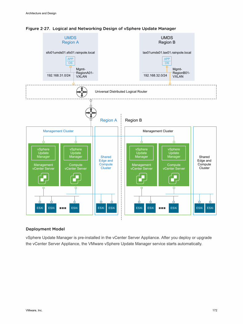
Figure 2‑27. Logical and Networking Design of vSphere Update Manager
APPOS
APPOS
UMDSRegion A
Management Cluster
SharedEdge andComputeCluster
ESXi ESXi ESXi ESXiESXi
Management Cluster
SharedEdge andComputeCluster
ESXi ESXi ESXi ESXiESXi
vSphereUpdate
Manager
ManagementvCenter Server
vSphereUpdate
Manager
ComputevCenter Server
192.168.31.0/24
Mgmt-RegionA01-VXLAN
sfo01umds01.sfo01.rainpole.local
UMDSRegion B
192.168.32.0/24
Mgmt-RegionB01-VXLAN
lax01umds01.lax01.rainpole.local
Universal Distributed Logical Router
Region A Region B
vSphereUpdate
Manager
ManagementvCenter Server
vSphereUpdate
Manager
ComputevCenter Server
Deployment Model
vSphere Update Manager is pre-installed in the vCenter Server Appliance. After you deploy or upgradethe vCenter Server Appliance, the VMware vSphere Update Manager service starts automatically.
Architecture and Design
VMware, Inc. 172
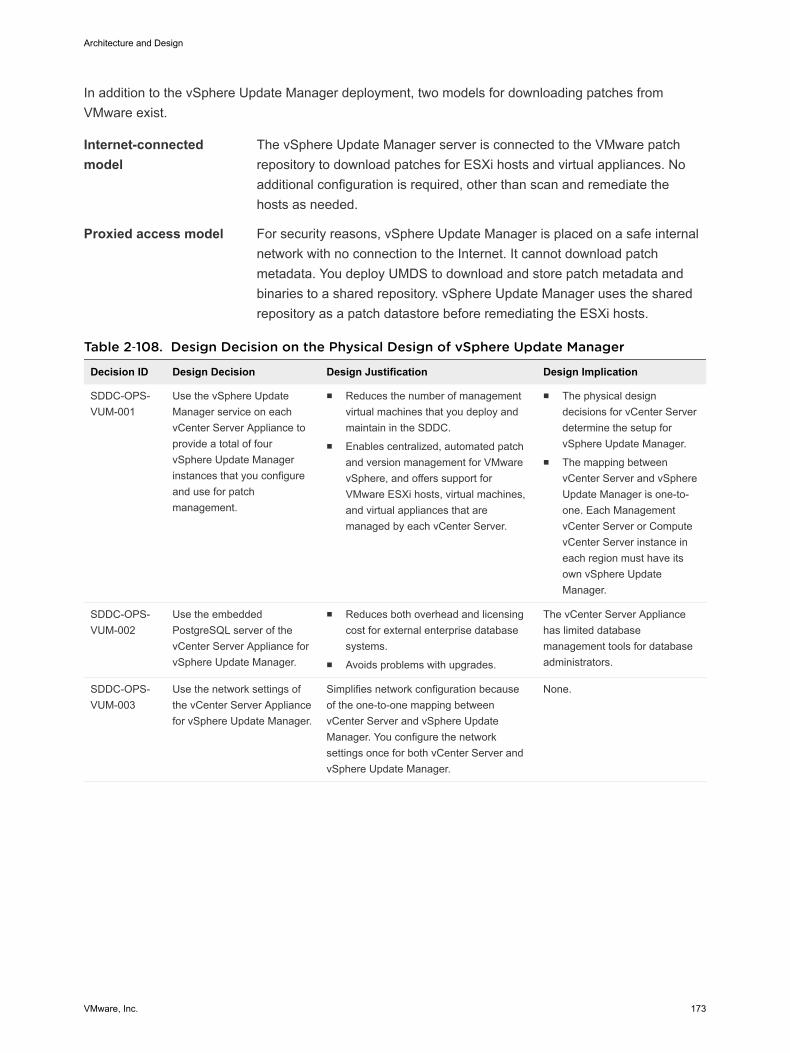
In addition to the vSphere Update Manager deployment, two models for downloading patches fromVMware exist.
Internet-connectedmodel
The vSphere Update Manager server is connected to the VMware patchrepository to download patches for ESXi hosts and virtual appliances. Noadditional configuration is required, other than scan and remediate thehosts as needed.
Proxied access model For security reasons, vSphere Update Manager is placed on a safe internalnetwork with no connection to the Internet. It cannot download patchmetadata. You deploy UMDS to download and store patch metadata andbinaries to a shared repository. vSphere Update Manager uses the sharedrepository as a patch datastore before remediating the ESXi hosts.
Table 2‑108. Design Decision on the Physical Design of vSphere Update Manager
Decision ID Design Decision Design Justification Design Implication
SDDC-OPS-VUM-001
Use the vSphere UpdateManager service on eachvCenter Server Appliance toprovide a total of fourvSphere Update Managerinstances that you configureand use for patchmanagement.
n Reduces the number of managementvirtual machines that you deploy andmaintain in the SDDC.
n Enables centralized, automated patchand version management for VMwarevSphere, and offers support forVMware ESXi hosts, virtual machines,and virtual appliances that aremanaged by each vCenter Server.
n The physical designdecisions for vCenter Serverdetermine the setup forvSphere Update Manager.
n The mapping betweenvCenter Server and vSphereUpdate Manager is one-to-one. Each ManagementvCenter Server or ComputevCenter Server instance ineach region must have itsown vSphere UpdateManager.
SDDC-OPS-VUM-002
Use the embeddedPostgreSQL server of thevCenter Server Appliance forvSphere Update Manager.
n Reduces both overhead and licensingcost for external enterprise databasesystems.
n Avoids problems with upgrades.
The vCenter Server Appliancehas limited databasemanagement tools for databaseadministrators.
SDDC-OPS-VUM-003
Use the network settings ofthe vCenter Server Appliancefor vSphere Update Manager.
Simplifies network configuration becauseof the one-to-one mapping betweenvCenter Server and vSphere UpdateManager. You configure the networksettings once for both vCenter Server andvSphere Update Manager.
None.
Architecture and Design
VMware, Inc. 173
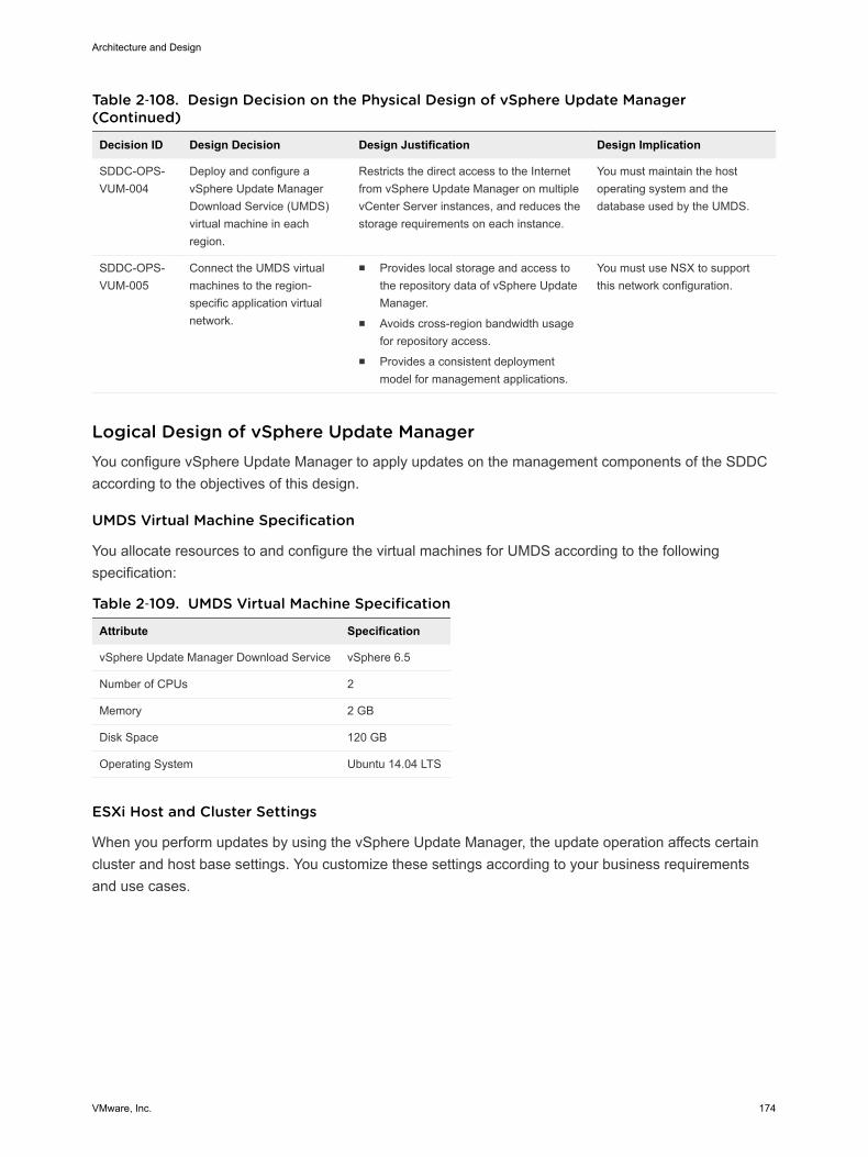
Table 2‑108. Design Decision on the Physical Design of vSphere Update Manager(Continued)
Decision ID Design Decision Design Justification Design Implication
SDDC-OPS-VUM-004
Deploy and configure avSphere Update ManagerDownload Service (UMDS)virtual machine in eachregion.
Restricts the direct access to the Internetfrom vSphere Update Manager on multiplevCenter Server instances, and reduces thestorage requirements on each instance.
You must maintain the hostoperating system and thedatabase used by the UMDS.
SDDC-OPS-VUM-005
Connect the UMDS virtualmachines to the region-specific application virtualnetwork.
n Provides local storage and access tothe repository data of vSphere UpdateManager.
n Avoids cross-region bandwidth usagefor repository access.
n Provides a consistent deploymentmodel for management applications.
You must use NSX to supportthis network configuration.
Logical Design of vSphere Update Manager You configure vSphere Update Manager to apply updates on the management components of the SDDCaccording to the objectives of this design.
UMDS Virtual Machine Specification
You allocate resources to and configure the virtual machines for UMDS according to the followingspecification:
Table 2‑109. UMDS Virtual Machine Specification
Attribute Specification
vSphere Update Manager Download Service vSphere 6.5
Number of CPUs 2
Memory 2 GB
Disk Space 120 GB
Operating System Ubuntu 14.04 LTS
ESXi Host and Cluster Settings
When you perform updates by using the vSphere Update Manager, the update operation affects certaincluster and host base settings. You customize these settings according to your business requirementsand use cases.
Architecture and Design
VMware, Inc. 174

Table 2‑110. Host and Cluster Settings That Are Affected by vSphere Update Manager
Settings Description
Maintenance mode During remediation, updates might require the host to enter maintenance mode.
Virtual machines cannot run when a host is in maintenance mode. For availability during a hostupdate, virtual machines are migrated to the other ESXi hosts in a cluster before the host entersmaintenance mode. However, putting a host in maintenance mode during update might causeissues with the availability of the cluster.
vSAN When using vSAN, consider the following factors when you update hosts by using vSphere UpdateManager:n Host remediation might take a significant amount of time to complete because, by design, only
one host from a vSAN cluster can be in maintenance mode at one time.n vSphere Update Manager remediates hosts that are a part of a vSAN cluster sequentially, even
if you set the option to remediate the hosts in parallel.n If the number of failures to tolerate is set to 0 for the vSAN cluster, the host might experience
delays when entering maintenance mode. The delay occurs because vSAN copies databetween the storage devices in the cluster.
To avoid delays, use the default vSAN policy where the number of failures to tolerate is 1.
You can control the update operation by using a set of host and cluster settings in vSphere UpdateManager.
Table 2‑111. Host and Cluster Settings for Updates
Level Setting Description
Host settings VM power state when entering maintenancemode
You can configure vSphere Update Manager to power off,suspend, or do not control virtual machines duringremediation. This option applies only if vSphere vMotion isnot available for a host.
Retry maintenance mode in case of failure If a host fails to enter maintenance mode before remediation,vSphere Update Manager waits for a retry delay period andretries putting the host into maintenance mode as many timesas you indicate.
Allow installation of additional software onPXE-booted hosts
You can install solution software on PXE-booted ESXi hosts.This option is limited to software packages that do not requirea host reboot after installation.
Clustersettings
Disable vSphere Distributed PowerManagement (DPM), vSphere High Availability(HA) Admission Control, and Fault Tolerance(FT)
vSphere Update Manager can remediate only clusters withdisabled vSphere DPM, vSphere HA, and vSphere FT.
Enable parallel remediation of hosts vSphere Update Manager can remediate multiple hosts.
Note Parallel remediation is not supported if you use vSAN.Remediation is performed serially for the ESXi hosts.
Migrate powered-off or suspended virtualmachines
vSphere Update Manager migrates the suspended andpowered-off virtual machines from hosts that must entermaintenance mode to other hosts in the cluster. The migrationis launched on virtual machines that do not prevent the hostfrom entering maintenance mode.
Architecture and Design
VMware, Inc. 175
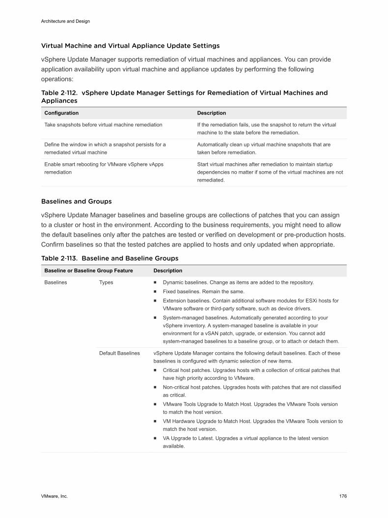
Virtual Machine and Virtual Appliance Update Settings
vSphere Update Manager supports remediation of virtual machines and appliances. You can provideapplication availability upon virtual machine and appliance updates by performing the followingoperations:
Table 2‑112. vSphere Update Manager Settings for Remediation of Virtual Machines andAppliances
Configuration Description
Take snapshots before virtual machine remediation If the remediation fails, use the snapshot to return the virtualmachine to the state before the remediation.
Define the window in which a snapshot persists for aremediated virtual machine
Automatically clean up virtual machine snapshots that aretaken before remediation.
Enable smart rebooting for VMware vSphere vAppsremediation
Start virtual machines after remediation to maintain startupdependencies no matter if some of the virtual machines are notremediated.
Baselines and Groups
vSphere Update Manager baselines and baseline groups are collections of patches that you can assignto a cluster or host in the environment. According to the business requirements, you might need to allowthe default baselines only after the patches are tested or verified on development or pre-production hosts.Confirm baselines so that the tested patches are applied to hosts and only updated when appropriate.
Table 2‑113. Baseline and Baseline Groups
Baseline or Baseline Group Feature Description
Baselines Types n Dynamic baselines. Change as items are added to the repository.n Fixed baselines. Remain the same.n Extension baselines. Contain additional software modules for ESXi hosts for
VMware software or third-party software, such as device drivers.n System-managed baselines. Automatically generated according to your
vSphere inventory. A system-managed baseline is available in yourenvironment for a vSAN patch, upgrade, or extension. You cannot addsystem-managed baselines to a baseline group, or to attach or detach them.
Default Baselines vSphere Update Manager contains the following default baselines. Each of thesebaselines is configured with dynamic selection of new items.n Critical host patches. Upgrades hosts with a collection of critical patches that
have high priority according to VMware.n Non-critical host patches. Upgrades hosts with patches that are not classified
as critical.n VMware Tools Upgrade to Match Host. Upgrades the VMware Tools version
to match the host version.n VM Hardware Upgrade to Match Host. Upgrades the VMware Tools version to
match the host version.n VA Upgrade to Latest. Upgrades a virtual appliance to the latest version
available.
Architecture and Design
VMware, Inc. 176
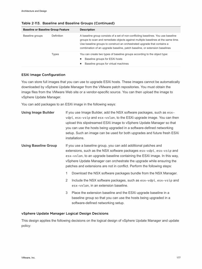
Table 2‑113. Baseline and Baseline Groups (Continued)
Baseline or Baseline Group Feature Description
Baseline groups Definition A baseline group consists of a set of non-conflicting baselines. You use baselinegroups to scan and remediate objects against multiple baselines at the same time.Use baseline groups to construct an orchestrated upgrade that contains acombination of an upgrade baseline, patch baseline, or extension baselines
Types You can create two types of baseline groups according to the object type:n Baseline groups for ESXi hostsn Baseline groups for virtual machines
ESXi Image Configuration
You can store full images that you can use to upgrade ESXi hosts. These images cannot be automaticallydownloaded by vSphere Update Manager from the VMware patch repositories. You must obtain theimage files from the VMware Web site or a vendor-specific source. You can then upload the image tovSphere Update Manager.
You can add packages to an ESXi image in the following ways:
Using Image Builder If you use Image Builder, add the NSX software packages, such as esx-vdpi, esx-vsip and esx-vxlan, to the ESXi upgrade image. You can thenupload this slipstreamed ESXi image to vSphere Update Manager so thatyou can use the hosts being upgraded in a software-defined networkingsetup. Such an image can be used for both upgrades and future fresh ESXiinstallations.
Using Baseline Group If you use a baseline group, you can add additional patches andextensions, such as the NSX software packages esx-vdpi, esx-vsip andesx-vxlan, to an upgrade baseline containing the ESXi image. In this way,vSphere Update Manager can orchestrate the upgrade while ensuring thepatches and extensions are not in conflict. Perform the following steps:
1 Download the NSX software packages bundle from the NSX Manager.
2 Include the NSX software packages, such as esx-vdpi, esx-vsip andesx-vxlan, in an extension baseline.
3 Place the extension baseline and the ESXi upgrade baseline in abaseline group so that you can use the hosts being upgraded in asoftware-defined networking setup.
vSphere Update Manager Logical Design Decisions
This design applies the following decisions on the logical design of vSphere Update Manager and updatepolicy:
Architecture and Design
VMware, Inc. 177
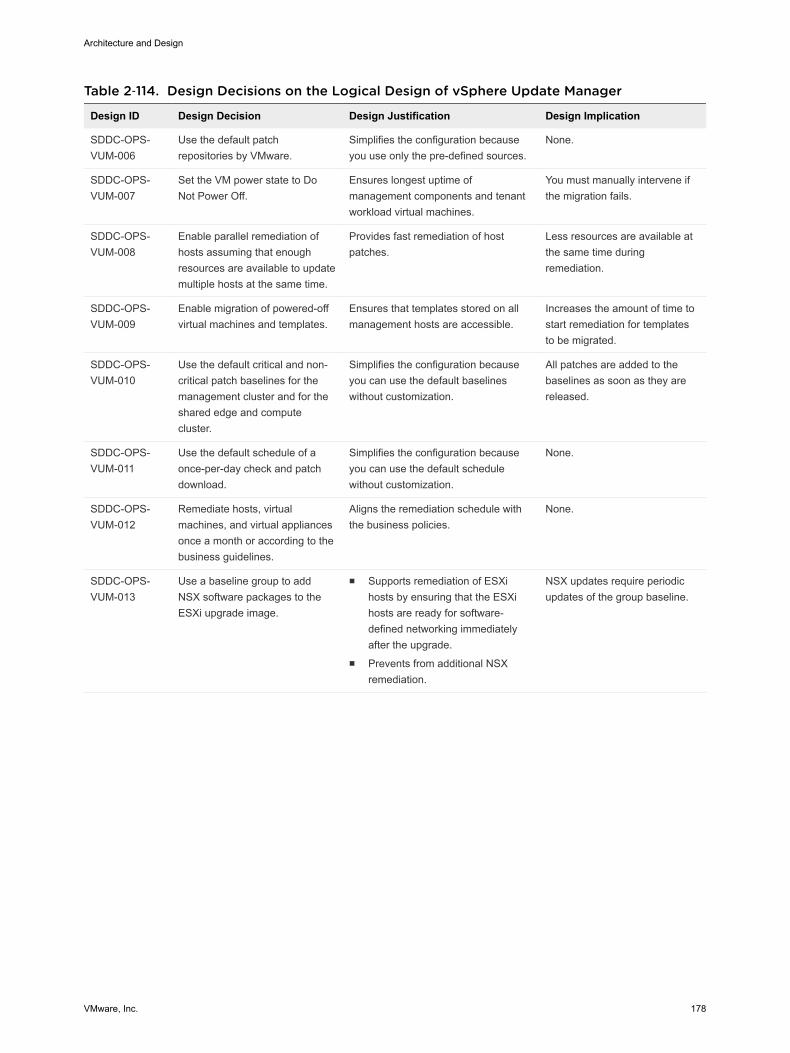
Table 2‑114. Design Decisions on the Logical Design of vSphere Update Manager
Design ID Design Decision Design Justification Design Implication
SDDC-OPS-VUM-006
Use the default patchrepositories by VMware.
Simplifies the configuration becauseyou use only the pre-defined sources.
None.
SDDC-OPS-VUM-007
Set the VM power state to DoNot Power Off.
Ensures longest uptime ofmanagement components and tenantworkload virtual machines.
You must manually intervene ifthe migration fails.
SDDC-OPS-VUM-008
Enable parallel remediation ofhosts assuming that enoughresources are available to updatemultiple hosts at the same time.
Provides fast remediation of hostpatches.
Less resources are available atthe same time duringremediation.
SDDC-OPS-VUM-009
Enable migration of powered-offvirtual machines and templates.
Ensures that templates stored on allmanagement hosts are accessible.
Increases the amount of time tostart remediation for templatesto be migrated.
SDDC-OPS-VUM-010
Use the default critical and non-critical patch baselines for themanagement cluster and for theshared edge and computecluster.
Simplifies the configuration becauseyou can use the default baselineswithout customization.
All patches are added to thebaselines as soon as they arereleased.
SDDC-OPS-VUM-011
Use the default schedule of aonce-per-day check and patchdownload.
Simplifies the configuration becauseyou can use the default schedulewithout customization.
None.
SDDC-OPS-VUM-012
Remediate hosts, virtualmachines, and virtual appliancesonce a month or according to thebusiness guidelines.
Aligns the remediation schedule withthe business policies.
None.
SDDC-OPS-VUM-013
Use a baseline group to addNSX software packages to theESXi upgrade image.
n Supports remediation of ESXihosts by ensuring that the ESXihosts are ready for software-defined networking immediatelyafter the upgrade.
n Prevents from additional NSXremediation.
NSX updates require periodicupdates of the group baseline.
Architecture and Design
VMware, Inc. 178
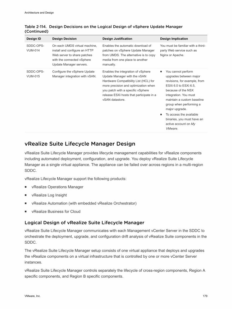
Table 2‑114. Design Decisions on the Logical Design of vSphere Update Manager(Continued)
Design ID Design Decision Design Justification Design Implication
SDDC-OPS-VUM-014
On each UMDS virtual machine,install and configure an HTTPWeb server to share patcheswith the connected vSphereUpdate Manager servers.
Enables the automatic download ofpatches on vSphere Update Managerfrom UMDS. The alternative is to copymedia from one place to anothermanually.
You must be familiar with a third-party Web service such asNginx or Apache.
SDDC-OPS-VUM-015
Configure the vSphere UpdateManager integration with vSAN.
Enables the integration of vSphereUpdate Manager with the vSANHardware Compatibility List (HCL) formore precision and optimization whenyou patch with a specific vSphererelease ESXi hosts that participate in avSAN datastore.
n You cannot performupgrades between majorrevisions, for example, fromESXi 6.0 to ESXi 6.5,because of the NSXintegration. You mustmaintain a custom baselinegroup when performing amajor upgrade.
n To access the availablebinaries, you must have anactive account on MyVMware.
vRealize Suite Lifecycle Manager Design vRealize Suite Lifecycle Manager provides lifecycle management capabilities for vRealize componentsincluding automated deployment, configuration, and upgrade. You deploy vRealize Suite LifecycleManager as a single virtual appliance. The appliance can be failed over across regions in a multi-regionSDDC.
vRealize Lifecycle Manager support the following products:
n vRealize Operations Manager
n vRealize Log Insight
n vRealize Automation (with embedded vRealize Orchestrator)
n vRealize Business for Cloud
Logical Design of vRealize Suite Lifecycle Manager vRealize Suite Lifecycle Manager communicates with each Management vCenter Server in the SDDC toorchestrate the deployment, upgrade, and configuration drift analysis of vRealize Suite components in theSDDC.
The vRealize Suite Lifecycle Manager setup consists of one virtual appliance that deploys and upgradesthe vRealize components on a virtual infrastructure that is controlled by one or more vCenter Serverinstances.
vRealize Suite Lifecycle Manager controls separately the lifecycle of cross-region components, Region Aspecific components, and Region B specific components.
Architecture and Design
VMware, Inc. 179
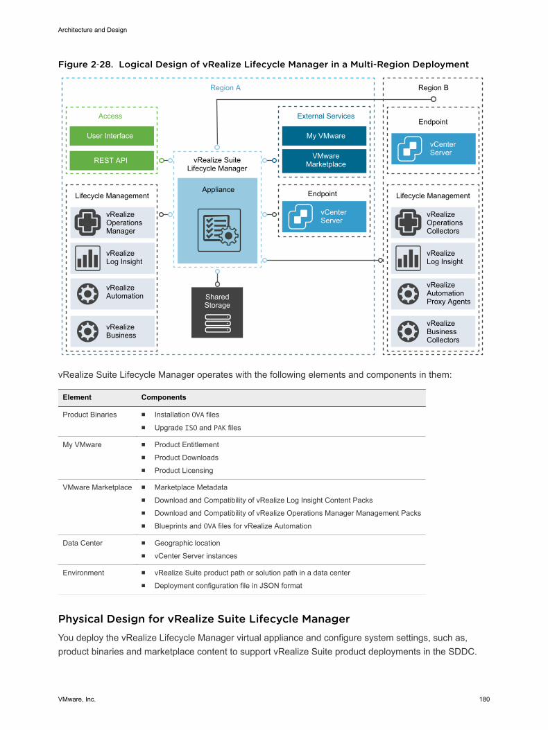
Figure 2‑28. Logical Design of vRealize Lifecycle Manager in a Multi-Region Deployment
vRealizeAutomation
vRealizeLog Insight
vRealizeOperationsManager
Lifecycle Management Lifecycle Management
SharedStorage
Appliance
vRealize SuiteLifecycle Manager
vCenterServer
Endpoint
VMware Marketplace
My VMware
External Services
REST API
User Interface
Access
Region A
vCenterServer
vRealizeBusinessCollectors
vRealizeAutomationProxy Agents
vRealizeLog Insight
vRealizeOperationsCollectors
Region B
Endpoint
vRealizeBusiness
vRealize Suite Lifecycle Manager operates with the following elements and components in them:
Element Components
Product Binaries n Installation OVA filesn Upgrade ISO and PAK files
My VMware n Product Entitlementn Product Downloadsn Product Licensing
VMware Marketplace n Marketplace Metadatan Download and Compatibility of vRealize Log Insight Content Packsn Download and Compatibility of vRealize Operations Manager Management Packsn Blueprints and OVA files for vRealize Automation
Data Center n Geographic locationn vCenter Server instances
Environment n vRealize Suite product path or solution path in a data centern Deployment configuration file in JSON format
Physical Design for vRealize Suite Lifecycle Manager You deploy the vRealize Lifecycle Manager virtual appliance and configure system settings, such as,product binaries and marketplace content to support vRealize Suite product deployments in the SDDC.
Architecture and Design
VMware, Inc. 180
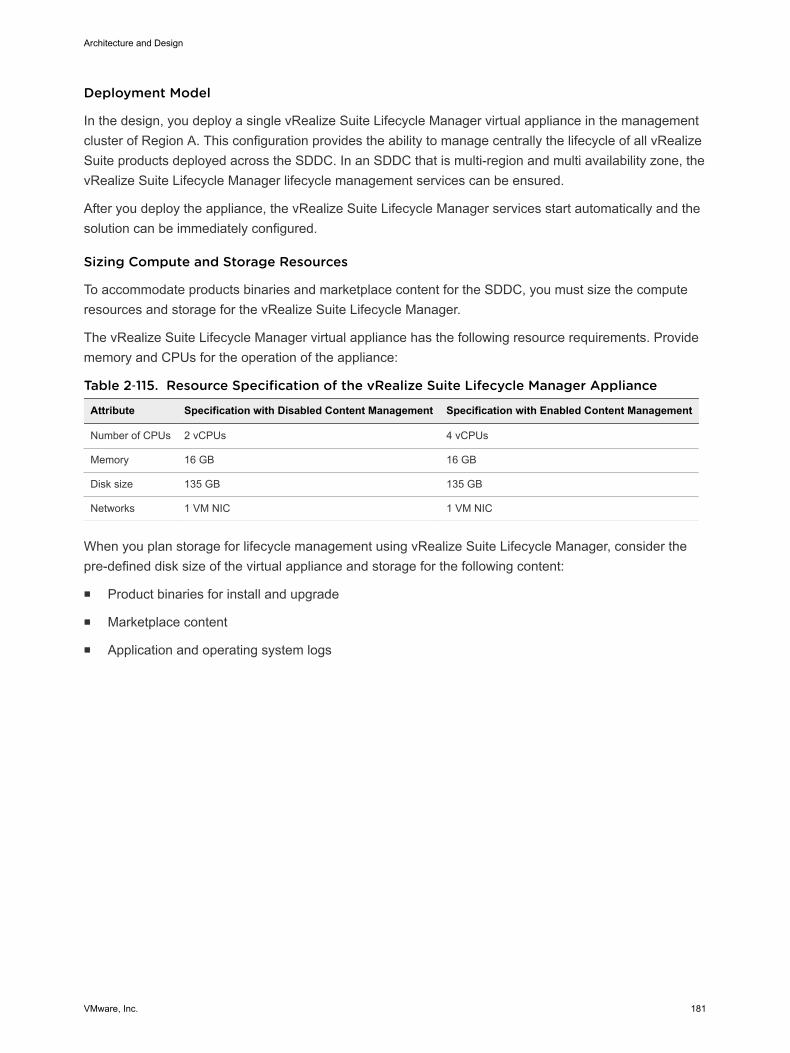
Deployment Model
In the design, you deploy a single vRealize Suite Lifecycle Manager virtual appliance in the managementcluster of Region A. This configuration provides the ability to manage centrally the lifecycle of all vRealizeSuite products deployed across the SDDC. In an SDDC that is multi-region and multi availability zone, thevRealize Suite Lifecycle Manager lifecycle management services can be ensured.
After you deploy the appliance, the vRealize Suite Lifecycle Manager services start automatically and thesolution can be immediately configured.
Sizing Compute and Storage Resources
To accommodate products binaries and marketplace content for the SDDC, you must size the computeresources and storage for the vRealize Suite Lifecycle Manager.
The vRealize Suite Lifecycle Manager virtual appliance has the following resource requirements. Providememory and CPUs for the operation of the appliance:
Table 2‑115. Resource Specification of the vRealize Suite Lifecycle Manager Appliance
Attribute Specification with Disabled Content Management Specification with Enabled Content Management
Number of CPUs 2 vCPUs 4 vCPUs
Memory 16 GB 16 GB
Disk size 135 GB 135 GB
Networks 1 VM NIC 1 VM NIC
When you plan storage for lifecycle management using vRealize Suite Lifecycle Manager, consider thepre-defined disk size of the virtual appliance and storage for the following content:
n Product binaries for install and upgrade
n Marketplace content
n Application and operating system logs
Architecture and Design
VMware, Inc. 181
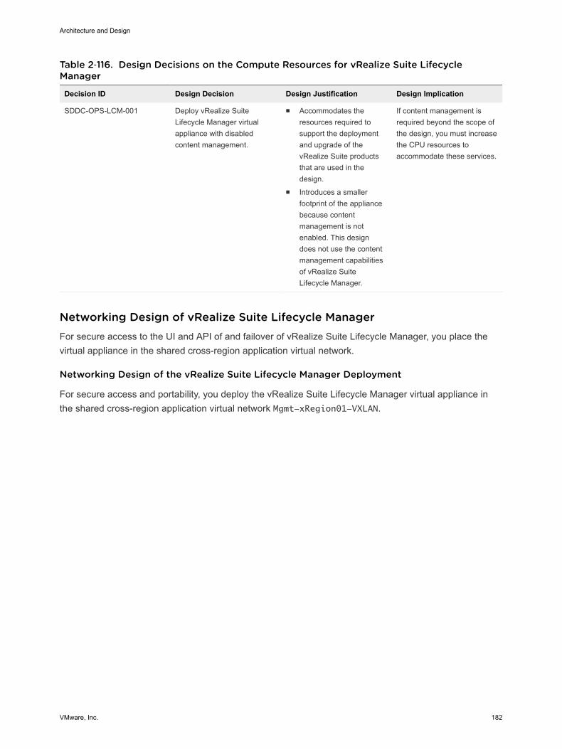
Table 2‑116. Design Decisions on the Compute Resources for vRealize Suite LifecycleManager
Decision ID Design Decision Design Justification Design Implication
SDDC-OPS-LCM-001 Deploy vRealize SuiteLifecycle Manager virtualappliance with disabledcontent management.
n Accommodates theresources required tosupport the deploymentand upgrade of thevRealize Suite productsthat are used in thedesign.
n Introduces a smallerfootprint of the appliancebecause contentmanagement is notenabled. This designdoes not use the contentmanagement capabilitiesof vRealize SuiteLifecycle Manager.
If content management isrequired beyond the scope ofthe design, you must increasethe CPU resources toaccommodate these services.
Networking Design of vRealize Suite Lifecycle Manager For secure access to the UI and API of and failover of vRealize Suite Lifecycle Manager, you place thevirtual appliance in the shared cross-region application virtual network.
Networking Design of the vRealize Suite Lifecycle Manager Deployment
For secure access and portability, you deploy the vRealize Suite Lifecycle Manager virtual appliance inthe shared cross-region application virtual network Mgmt-xRegion01-VXLAN.
Architecture and Design
VMware, Inc. 182
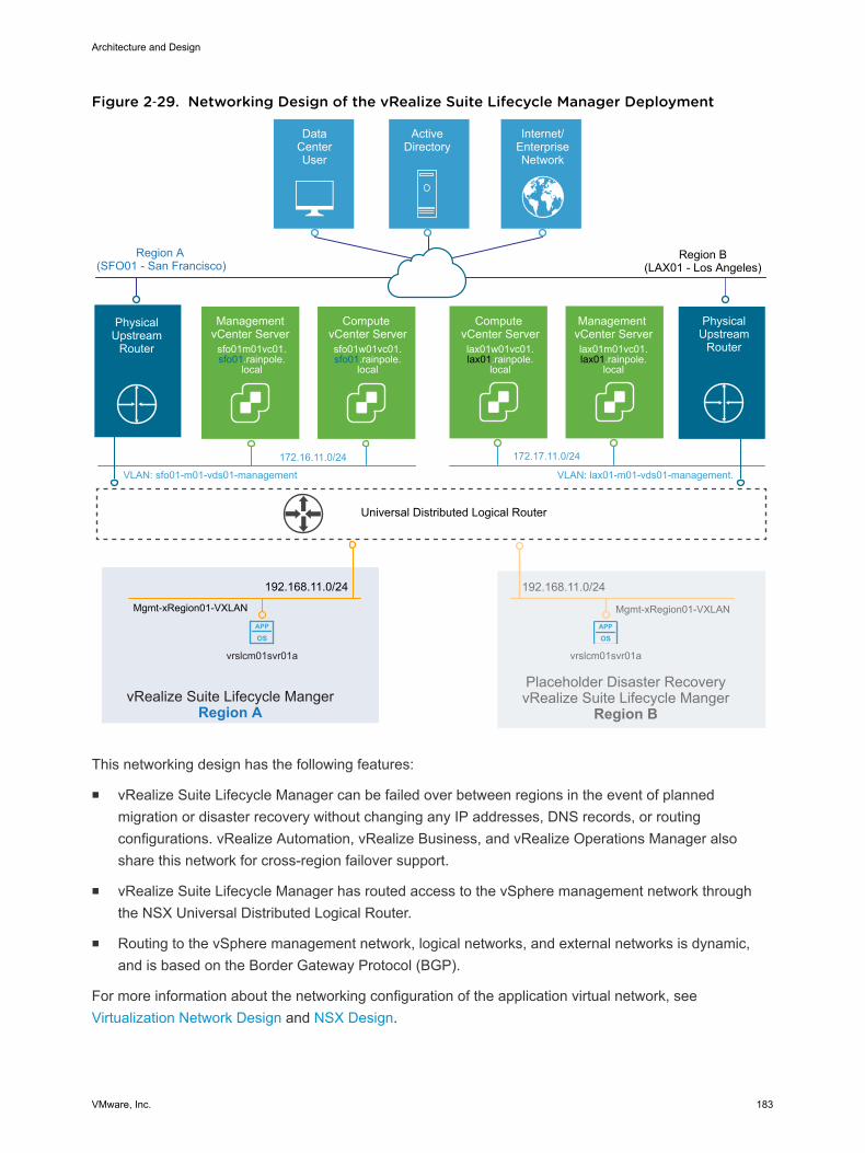
Figure 2‑29. Networking Design of the vRealize Suite Lifecycle Manager Deployment
APP
OSAPP
OS
Universal Distributed Logical Router
DataCenterUser
ActiveDirectory
Internet/EnterpriseNetwork
Region A(SFO01 - San Francisco)
Management vCenter Serverlax01m01vc01.lax01.rainpole.
local
Compute vCenter Serverlax01w01vc01.lax01.rainpole.
local
VLAN: sfo01-m01-vds01-management
172.16.11.0/24
VLAN: lax01-m01-vds01-management.
172.17.11.0/24
Management vCenter Server
sfo01m01vc01.sfo01.rainpole.
local
Compute vCenter Serversfo01w01vc01.sfo01.rainpole.
local
PhysicalUpstream
Router
vrslcm01svr01a
192.168.11.0/24
Mgmt-xRegion01-VXLAN
vRealize Suite Lifecycle MangerRegion A
Region B(LAX01 - Los Angeles)
PhysicalUpstream
Router
vrslcm01svr01a
192.168.11.0/24
Placeholder Disaster RecoveryvRealize Suite Lifecycle Manger
Region B
Mgmt-xRegion01-VXLAN
This networking design has the following features:
n vRealize Suite Lifecycle Manager can be failed over between regions in the event of plannedmigration or disaster recovery without changing any IP addresses, DNS records, or routingconfigurations. vRealize Automation, vRealize Business, and vRealize Operations Manager alsoshare this network for cross-region failover support.
n vRealize Suite Lifecycle Manager has routed access to the vSphere management network throughthe NSX Universal Distributed Logical Router.
n Routing to the vSphere management network, logical networks, and external networks is dynamic,and is based on the Border Gateway Protocol (BGP).
For more information about the networking configuration of the application virtual network, see Virtualization Network Design and NSX Design.
Architecture and Design
VMware, Inc. 183
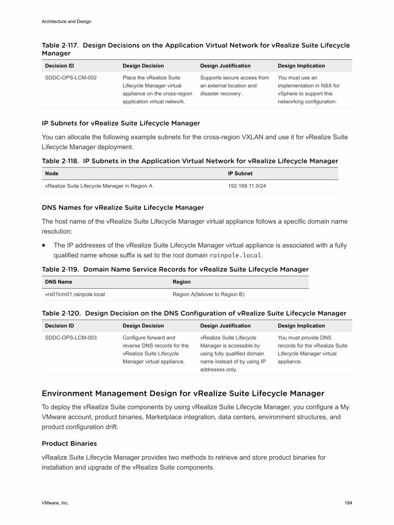
Table 2‑117. Design Decisions on the Application Virtual Network for vRealize Suite LifecycleManager
Decision ID Design Decision Design Justification Design Implication
SDDC-OPS-LCM-002 Place the vRealize SuiteLifecycle Manager virtualappliance on the cross-regionapplication virtual network.
Supports secure access froman external location anddisaster recovery .
You must use animplementation in NSX forvSphere to support thisnetworking configuration.
IP Subnets for vRealize Suite Lifecycle Manager
You can allocate the following example subnets for the cross-region VXLAN and use it for vRealize SuiteLifecycle Manager deployment.
Table 2‑118. IP Subnets in the Application Virtual Network for vRealize Lifecycle Manager
Node IP Subnet
vRealize Suite Lifecycle Manager in Region A 192.168.11.0/24
DNS Names for vRealize Suite Lifecycle Manager
The host name of the vRealize Suite Lifecycle Manager virtual appliance follows a specific domain nameresolution:
n The IP addresses of the vRealize Suite Lifecycle Manager virtual appliance is associated with a fullyqualified name whose suffix is set to the root domain rainpole.local.
Table 2‑119. Domain Name Service Records for vRealize Suite Lifecycle Manager
DNS Name Region
vrs01lcm01.rainpole.local Region A(failover to Region B)
Table 2‑120. Design Decision on the DNS Configuration of vRealize Suite Lifecycle Manager
Decision ID Design Decision Design Justification Design Implication
SDDC-OPS-LCM-003 Configure forward andreverse DNS records for thevRealize Suite LifecycleManager virtual appliance.
vRealize Suite LifecycleManager is accessible byusing fully qualified domainname instead of by using IPaddresses only.
You must provide DNSrecords for the vRealize SuiteLifecycle Manager virtualappliance.
Environment Management Design for vRealize Suite Lifecycle Manager To deploy the vRealize Suite components by using vRealize Suite Lifecycle Manager, you configure a MyVMware account, product binaries, Marketplace integration, data centers, environment structures, andproduct configuration drift.
Product Binaries
vRealize Suite Lifecycle Manager provides two methods to retrieve and store product binaries forinstallation and upgrade of the vRealize Suite components.
Architecture and Design
VMware, Inc. 184
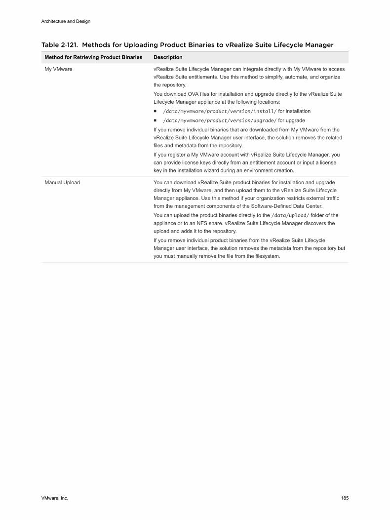
Table 2‑121. Methods for Uploading Product Binaries to vRealize Suite Lifecycle Manager
Method for Retrieving Product Binaries Description
My VMware vRealize Suite Lifecycle Manager can integrate directly with My VMware to accessvRealize Suite entitlements. Use this method to simplify, automate, and organizethe repository.
You download OVA files for installation and upgrade directly to the vRealize SuiteLifecycle Manager appliance at the following locations:n /data/myvmware/product/version/install/ for installationn /data/myvmware/product/version/upgrade/ for upgrade
If you remove individual binaries that are downloaded from My VMware from thevRealize Suite Lifecycle Manager user interface, the solution removes the relatedfiles and metadata from the repository.
If you register a My VMware account with vRealize Suite Lifecycle Manager, youcan provide license keys directly from an entitlement account or input a licensekey in the installation wizard during an environment creation.
Manual Upload You can download vRealize Suite product binaries for installation and upgradedirectly from My VMware, and then upload them to the vRealize Suite LifecycleManager appliance. Use this method if your organization restricts external trafficfrom the management components of the Software-Defined Data Center.
You can upload the product binaries directly to the /data/upload/ folder of theappliance or to an NFS share. vRealize Suite Lifecycle Manager discovers theupload and adds it to the repository.
If you remove individual product binaries from the vRealize Suite LifecycleManager user interface, the solution removes the metadata from the repository butyou must manually remove the file from the filesystem.
Architecture and Design
VMware, Inc. 185

Table 2‑122. Design Decisions on Downloading Product Binaries in vRealize Suite LifecycleManager
Decision ID Design Decision Design Justification Design Implication
SDDC-OPS-LCM-004 Register the virtual applianceof vRealize Suite LifecycleManager with My VMware.
Provides the followingcapabilities:n Retrieve and use
vRealize Suite licenses inthe entitlement of the MyVMware account duringan SDDC deployment.
n Download vRealize Suitemarketplace content fromthe VMware Marketplaceto the repository.
n You must have a MyVMware account with therequired entitlement toaccess vRealize Suiteproduct downloads andlicenses.
n You must manage adedicated My VMwareaccount for use withvRealize Suite LifecycleManager.
n You must provide externalHTTPS access tovRealize Suite LifecycleManager for My VMwareand VMware Marketplaceendpoints.
SDDC-OPS-LCM-005 Use a dedicated My VMwareaccount for vRealize SuiteLifecycle Manager instead ofa named user account.
Provides the following accesscontrol features:n Accessibility and
privileges on thedestination serviceremain restricted to anintegration account.
n Accountability in trackinginteractions between theSDDC and My VMware.
n You must have a MyVMware account with therequired entitlement toaccess vRealize Suiteproduct downloads andlicenses.
n You must manage adedicated My VMwareaccount for use withvRealize Suite LifecycleManager.
SDDC-OPS-LCM-006 Download product binariesfrom My VMware to the virtualappliance of vRealize SuiteLifecycle Manager.
n Supports download andorganization of bothinstallation and upgradebinaries (.ova, .iso,and .pak) for eachvRealize Suite product inthis design to thevRealize Suite LifecycleManager repository.
n Reduces theadministrative overheadof downloading,uploading, and importingmedia to the vRealizeSuite Lifecycle Managerrepository.
n Supports adding productupgrades.
n You must have a MyVMware account with therequired entitlement toaccess vRealize Suiteproduct downloads andlicenses.
n You must provide morestorage because theworkflow downloads bothinstallation and upgrademedia for each product.
n If My VMware is notaccessible, you mustupload the productbinaries to the virtualappliance and register
Architecture and Design
VMware, Inc. 186
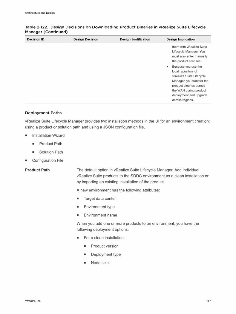
Table 2‑122. Design Decisions on Downloading Product Binaries in vRealize Suite LifecycleManager (Continued)
Decision ID Design Decision Design Justification Design Implication
them with vRealize SuiteLifecycle Manager. Youmust also enter manuallythe product licenses.
n Because you use thelocal repository ofvRealize Suite LifecycleManager, you transfer theproduct binaries acrossthe WAN during productdeployment and upgradeacross regions.
Deployment Paths
vRealize Suite Lifecycle Manager provides two installation methods in the UI for an environment creation:using a product or solution path and using a JSON configuration file.
n Installation Wizard
n Product Path
n Solution Path
n Configuration File
Product Path The default option in vRealize Suite Lifecycle Manager. Add individualvRealize Suite products to the SDDC environment as a clean installation orby importing an existing installation of the product.
A new environment has the following attributes:
n Target data center
n Environment type
n Environment name
When you add one or more products to an environment, you have thefollowing deployment options:
n For a clean installation:
n Product version
n Deployment type
n Node size
Architecture and Design
VMware, Inc. 187
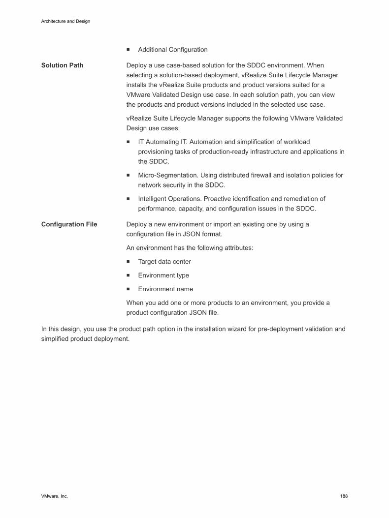
n Additional Configuration
Solution Path Deploy a use case-based solution for the SDDC environment. Whenselecting a solution-based deployment, vRealize Suite Lifecycle Managerinstalls the vRealize Suite products and product versions suited for aVMware Validated Design use case. In each solution path, you can viewthe products and product versions included in the selected use case.
vRealize Suite Lifecycle Manager supports the following VMware ValidatedDesign use cases:
n IT Automating IT. Automation and simplification of workloadprovisioning tasks of production-ready infrastructure and applications inthe SDDC.
n Micro-Segmentation. Using distributed firewall and isolation policies fornetwork security in the SDDC.
n Intelligent Operations. Proactive identification and remediation ofperformance, capacity, and configuration issues in the SDDC.
Configuration File Deploy a new environment or import an existing one by using aconfiguration file in JSON format.
An environment has the following attributes:
n Target data center
n Environment type
n Environment name
When you add one or more products to an environment, you provide aproduct configuration JSON file.
In this design, you use the product path option in the installation wizard for pre-deployment validation andsimplified product deployment.
Architecture and Design
VMware, Inc. 188
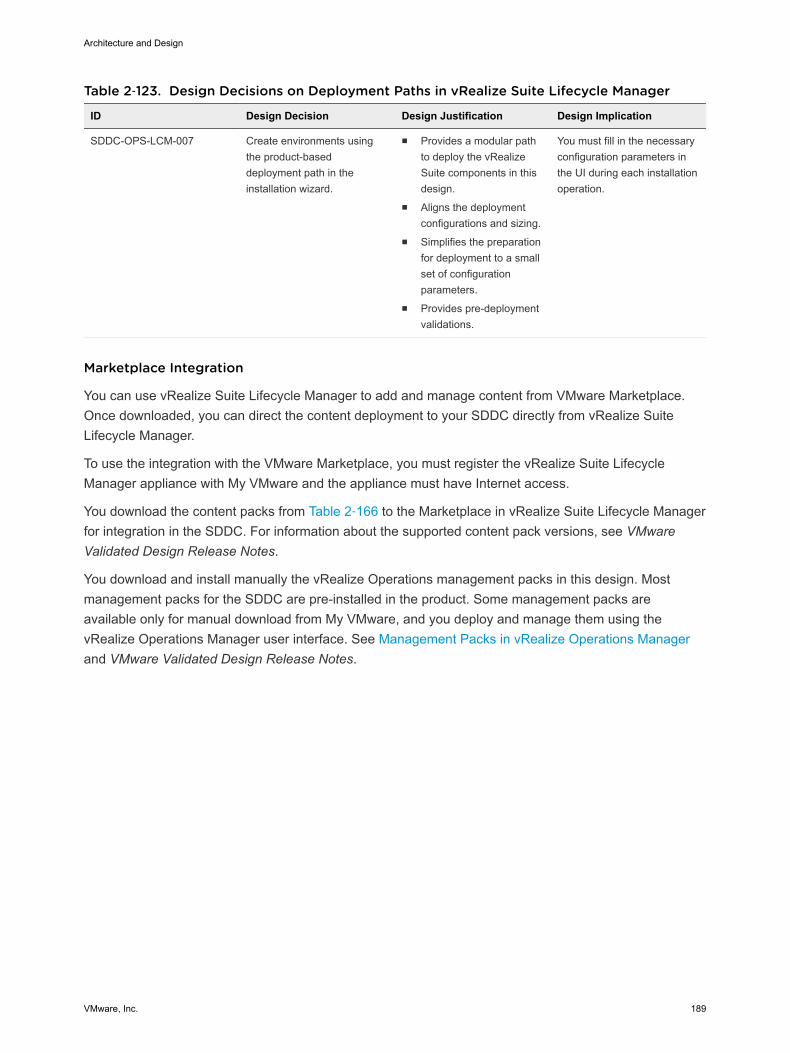
Table 2‑123. Design Decisions on Deployment Paths in vRealize Suite Lifecycle Manager
ID Design Decision Design Justification Design Implication
SDDC-OPS-LCM-007 Create environments usingthe product-baseddeployment path in theinstallation wizard.
n Provides a modular pathto deploy the vRealizeSuite components in thisdesign.
n Aligns the deploymentconfigurations and sizing.
n Simplifies the preparationfor deployment to a smallset of configurationparameters.
n Provides pre-deploymentvalidations.
You must fill in the necessaryconfiguration parameters inthe UI during each installationoperation.
Marketplace Integration
You can use vRealize Suite Lifecycle Manager to add and manage content from VMware Marketplace.Once downloaded, you can direct the content deployment to your SDDC directly from vRealize SuiteLifecycle Manager.
To use the integration with the VMware Marketplace, you must register the vRealize Suite LifecycleManager appliance with My VMware and the appliance must have Internet access.
You download the content packs from Table 2‑166 to the Marketplace in vRealize Suite Lifecycle Managerfor integration in the SDDC. For information about the supported content pack versions, see VMwareValidated Design Release Notes.
You download and install manually the vRealize Operations management packs in this design. Mostmanagement packs for the SDDC are pre-installed in the product. Some management packs areavailable only for manual download from My VMware, and you deploy and manage them using thevRealize Operations Manager user interface. See Management Packs in vRealize Operations Managerand VMware Validated Design Release Notes.
Architecture and Design
VMware, Inc. 189
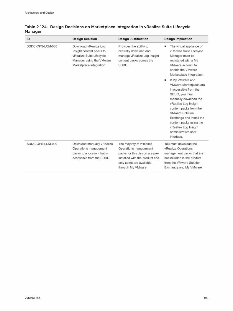
Table 2‑124. Design Decisions on Marketplace Integration in vRealize Suite LifecycleManager
ID Design Decision Design Justification Design Implication
SDDC-OPS-LCM-008 Download vRealize LogInsight content packs tovRealize Suite LifecycleManager using the VMwareMarketplace integration.
Provides the ability tocentrally download andmanage vRealize Log Insightcontent packs across theSDDC.
n The virtual appliance ofvRealize Suite LifecycleManager must beregistered with a MyVMware account toenable the VMwareMarketplace integration.
n If My VMware andVMware Marketplace areinaccessible from theSDDC, you mustmanually download thevRealize Log Insightcontent packs from theVMware SolutionExchange and install thecontent packs using thevRealize Log Insightadministrative userinterface.
SDDC-OPS-LCM-009 Download manually vRealizeOperations managementpacks to a location that isaccessible from the SDDC.
The majority of vRealizeOperations managementpacks for this design are pre-installed with the product andonly some are availablethrough My VMware.
You must download thevRealize Operationsmanagement packs that arenot included in the productfrom the VMware SolutionExchange and My VMware.
Architecture and Design
VMware, Inc. 190
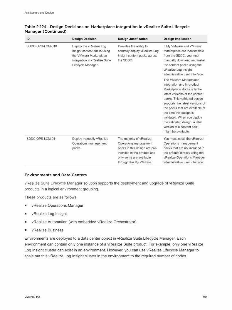
Table 2‑124. Design Decisions on Marketplace Integration in vRealize Suite LifecycleManager (Continued)
ID Design Decision Design Justification Design Implication
SDDC-OPS-LCM-010 Deploy the vRealize LogInsight content packs usingthe VMware Marketplaceintegration in vRealize SuiteLifecycle Manager.
Provides the ability tocentrally deploy vRealize LogInsight content packs acrossthe SDDC.
If My VMware and VMwareMarketplace are inaccessiblefrom the SDDC, you mustmanually download and installthe content packs using thevRealize Log Insightadministrative user interface.
The VMware Marketplaceintegration and in-productMarketplace stores only thelatest versions of the contentpacks. This validated designsupports the latest versions ofthe packs that are available atthe time this design isvalidated. When you deploythe validated design, a laterversion of a content packmight be available.
SDDC-OPS-LCM-011 Deploy manually vRealizeOperations managementpacks.
The majority of vRealizeOperations managementpacks in this design are pre-installed in the product andonly some are availablethrough the My VMware.
You must install the vRealizeOperations managementpacks that are not included inthe product directly using thevRealize Operations Manageradministrative user interface.
Environments and Data Centers
vRealize Suite Lifecycle Manager solution supports the deployment and upgrade of vRealize Suiteproducts in a logical environment grouping.
These products are as follows:
n vRealize Operations Manager
n vRealize Log Insight
n vRealize Automation (with embedded vRealize Orchestrator)
n vRealize Business
Environments are deployed to a data center object in vRealize Suite Lifecycle Manager. Eachenvironment can contain only one instance of a vRealize Suite product. For example, only one vRealizeLog Insight cluster can exist in an environment. However, you can use vRealize Lifecycle Manager toscale out this vRealize Log Insight cluster in the environment to the required number of nodes.
Architecture and Design
VMware, Inc. 191
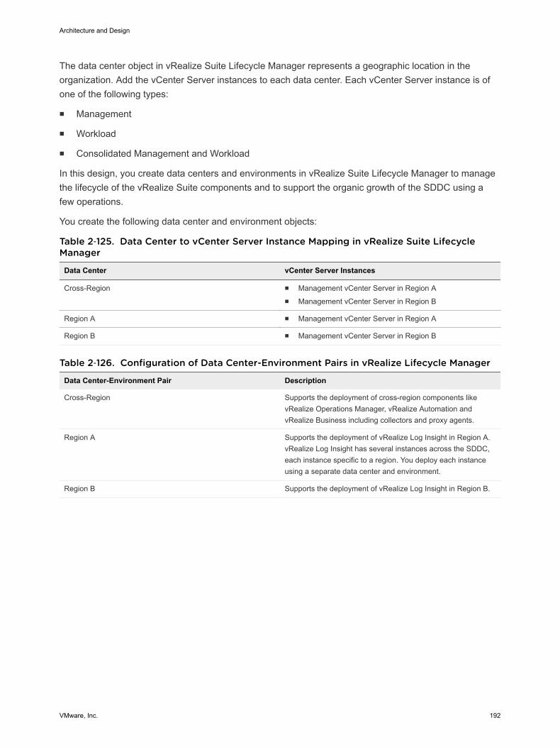
The data center object in vRealize Suite Lifecycle Manager represents a geographic location in theorganization. Add the vCenter Server instances to each data center. Each vCenter Server instance is ofone of the following types:
n Management
n Workload
n Consolidated Management and Workload
In this design, you create data centers and environments in vRealize Suite Lifecycle Manager to managethe lifecycle of the vRealize Suite components and to support the organic growth of the SDDC using afew operations.
You create the following data center and environment objects:
Table 2‑125. Data Center to vCenter Server Instance Mapping in vRealize Suite LifecycleManager
Data Center vCenter Server Instances
Cross-Region n Management vCenter Server in Region An Management vCenter Server in Region B
Region A n Management vCenter Server in Region A
Region B n Management vCenter Server in Region B
Table 2‑126. Configuration of Data Center-Environment Pairs in vRealize Lifecycle Manager
Data Center-Environment Pair Description
Cross-Region Supports the deployment of cross-region components likevRealize Operations Manager, vRealize Automation andvRealize Business including collectors and proxy agents.
Region A Supports the deployment of vRealize Log Insight in Region A.vRealize Log Insight has several instances across the SDDC,each instance specific to a region. You deploy each instanceusing a separate data center and environment.
Region B Supports the deployment of vRealize Log Insight in Region B.
Architecture and Design
VMware, Inc. 192
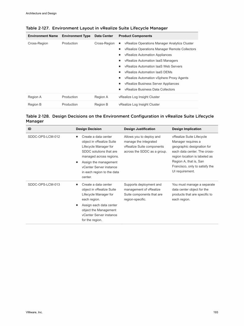
Table 2‑127. Environment Layout in vRealize Suite Lifecycle Manager
Environment Name Environment Type Data Center Product Components
Cross-Region Production Cross-Region n vRealize Operations Manager Analytics Clustern vRealize Operations Manager Remote Collectorsn vRealize Automation Appliancesn vRealize Automation IaaS Managersn vRealize Automation IaaS Web Serversn vRealize Automation IaaS DEMsn vRealize Automation vSphere Proxy Agentsn vRealize Business Server Appliancesn vRealize Business Data Collectors
Region A Production Region A vRealize Log Insight Cluster
Region B Production Region B vRealize Log Insight Cluster
Table 2‑128. Design Decisions on the Environment Configuration in vRealize Suite LifecycleManager
ID Design Decision Design Justification Design Implication
SDDC-OPS-LCM-012 n Create a data centerobject in vRealize SuiteLifecycle Manager forSDDC solutions that aremanaged across regions.
n Assign the managementvCenter Server instancein each region to the datacenter.
Allows you to deploy andmanage the integratedvRealize Suite componentsacross the SDDC as a group.
vRealize Suite LifecycleManager requires ageographic designation foreach data center. The cross-region location is labeled asRegion A, that is, SanFrancisco, only to satisfy theUI requirement.
SDDC-OPS-LCM-013 n Create a data centerobject in vRealize SuiteLifecycle Manager foreach region.
n Assign each data centerobject the ManagementvCenter Server instancefor the region.
Supports deployment andmanagement of vRealizeSuite components that areregion-specific.
You must manage a separatedata center object for theproducts that are specific toeach region.
Architecture and Design
VMware, Inc. 193
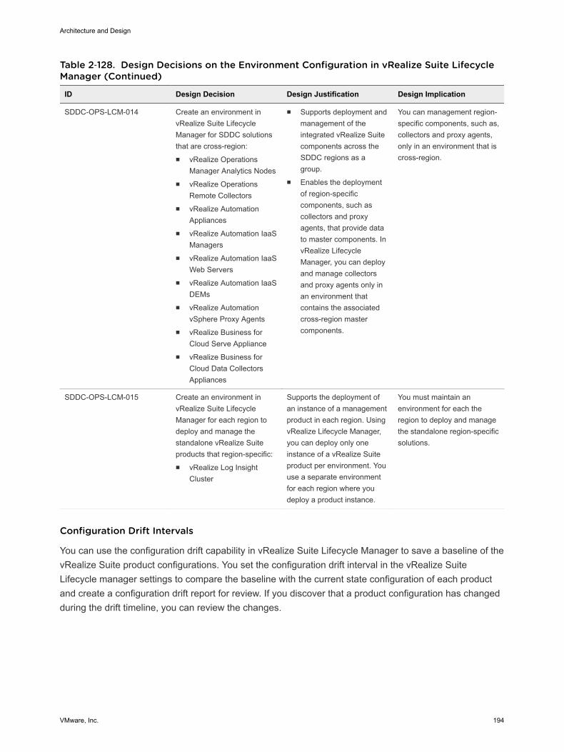
Table 2‑128. Design Decisions on the Environment Configuration in vRealize Suite LifecycleManager (Continued)
ID Design Decision Design Justification Design Implication
SDDC-OPS-LCM-014 Create an environment invRealize Suite LifecycleManager for SDDC solutionsthat are cross-region:n vRealize Operations
Manager Analytics Nodesn vRealize Operations
Remote Collectorsn vRealize Automation
Appliancesn vRealize Automation IaaS
Managersn vRealize Automation IaaS
Web Serversn vRealize Automation IaaS
DEMsn vRealize Automation
vSphere Proxy Agentsn vRealize Business for
Cloud Serve Appliancen vRealize Business for
Cloud Data CollectorsAppliances
n Supports deployment andmanagement of theintegrated vRealize Suitecomponents across theSDDC regions as agroup.
n Enables the deploymentof region-specificcomponents, such ascollectors and proxyagents, that provide datato master components. InvRealize LifecycleManager, you can deployand manage collectorsand proxy agents only inan environment thatcontains the associatedcross-region mastercomponents.
You can management region-specific components, such as,collectors and proxy agents,only in an environment that iscross-region.
SDDC-OPS-LCM-015 Create an environment invRealize Suite LifecycleManager for each region todeploy and manage thestandalone vRealize Suiteproducts that region-specific:n vRealize Log Insight
Cluster
Supports the deployment ofan instance of a managementproduct in each region. UsingvRealize Lifecycle Manager,you can deploy only oneinstance of a vRealize Suiteproduct per environment. Youuse a separate environmentfor each region where youdeploy a product instance.
You must maintain anenvironment for each theregion to deploy and managethe standalone region-specificsolutions.
Configuration Drift Intervals
You can use the configuration drift capability in vRealize Suite Lifecycle Manager to save a baseline of thevRealize Suite product configurations. You set the configuration drift interval in the vRealize SuiteLifecycle manager settings to compare the baseline with the current state configuration of each productand create a configuration drift report for review. If you discover that a product configuration has changedduring the drift timeline, you can review the changes.
Architecture and Design
VMware, Inc. 194

Table 2‑129. Design Decisions on the Configuration Drift Interval in vRealize Suite LifecycleManager
ID Design Decision Design Justification Design Implication
SDDC-OPS-LCM-016 Use the default configurationdrift interval.
The default configuration driftmonitors the changes invRealize Suite productconfigurations over each 24-hour period.
Drift analysis occurs onlyevery 24 hours.
SDDC-OPS-LCM-017 Create a baseline for eachproduct in an environmentpost-deployment and post-upgrade.
You can view any changes tothe current configuration ofthe product compared withthe configuration drift baselineof the product.
You must save theconfiguration baseline afterdeployment or upgrades.
Information Security and Access Design in vRealize Suite Lifecycle Manager You protect the vRealize Suite Lifecycle Manager deployment by configuring the authentication andsecure communication with the other components in the SDDC. You dedicate a service account to thecommunication between vRealize Suite Lifecycle Manager and vCenter Server.
You use a custom role in vSphere with permissions to perform lifecycle operations on vRealize Suitecomponents in the SDDC. A dedicated service account is assigned a custom role for communicationbetween vRealize Suite Lifecycle Manager and the vCenter Server instances in the environment.
Encryption
Access to all vRealize Suite Lifecycle Manager endpoint interfaces requires an SSL connection. Bydefault, vRealize Suite Lifecycle Manager uses a self-signed certificate for the appliance. To providesecure access to the vRealize Suite Lifecycle Manager and between SDDC endpoints, replace the defaultself-signed certificate with a CA-signed certificate.
Table 2‑130. Design Decisions on vRealize Suite Lifecycle Manager Encryption
ID Design Decision Design Justification Design Implication
SDDC-OPS-LCM-018 Replace the default self-signed certificate of the virtualappliance of vRealize SuiteLifecycle Manager with a CA-signed certificate.
Configuring a CA-signedcertificate ensures that thecommunication to theexternally facing Web UI andAPI for vRealize SuiteLifecycle Manager, and cross-product, is encrypted.
Replacing the defaultcertificates with trusted CA-signed certificates from acertificate authority mightincrease the deploymentpreparation time ascertificates requests aregenerated and delivered.
Authentication and Authorization
Users can authenticate to vRealize Suite Lifecycle Manager in the following ways:
n Local Administrator Account
n VMware Identity Manager
Architecture and Design
VMware, Inc. 195
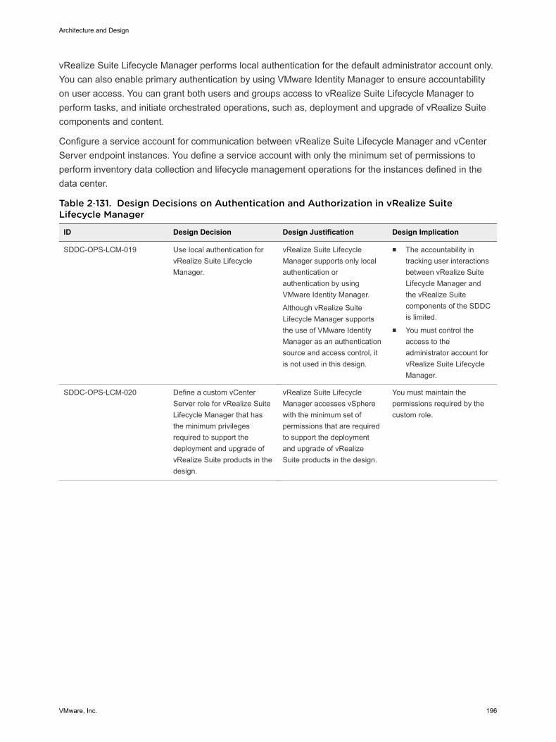
vRealize Suite Lifecycle Manager performs local authentication for the default administrator account only.You can also enable primary authentication by using VMware Identity Manager to ensure accountabilityon user access. You can grant both users and groups access to vRealize Suite Lifecycle Manager toperform tasks, and initiate orchestrated operations, such as, deployment and upgrade of vRealize Suitecomponents and content.
Configure a service account for communication between vRealize Suite Lifecycle Manager and vCenterServer endpoint instances. You define a service account with only the minimum set of permissions toperform inventory data collection and lifecycle management operations for the instances defined in thedata center.
Table 2‑131. Design Decisions on Authentication and Authorization in vRealize SuiteLifecycle Manager
ID Design Decision Design Justification Design Implication
SDDC-OPS-LCM-019 Use local authentication forvRealize Suite LifecycleManager.
vRealize Suite LifecycleManager supports only localauthentication orauthentication by usingVMware Identity Manager.
Although vRealize SuiteLifecycle Manager supportsthe use of VMware IdentityManager as an authenticationsource and access control, itis not used in this design.
n The accountability intracking user interactionsbetween vRealize SuiteLifecycle Manager andthe vRealize Suitecomponents of the SDDCis limited.
n You must control theaccess to theadministrator account forvRealize Suite LifecycleManager.
SDDC-OPS-LCM-020 Define a custom vCenterServer role for vRealize SuiteLifecycle Manager that hasthe minimum privilegesrequired to support thedeployment and upgrade ofvRealize Suite products in thedesign.
vRealize Suite LifecycleManager accesses vSpherewith the minimum set ofpermissions that are requiredto support the deploymentand upgrade of vRealizeSuite products in the design.
You must maintain thepermissions required by thecustom role.
Architecture and Design
VMware, Inc. 196
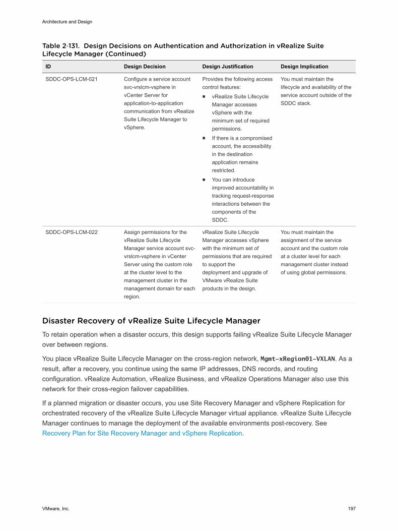
Table 2‑131. Design Decisions on Authentication and Authorization in vRealize SuiteLifecycle Manager (Continued)
ID Design Decision Design Justification Design Implication
SDDC-OPS-LCM-021 Configure a service accountsvc-vrslcm-vsphere invCenter Server forapplication-to-applicationcommunication from vRealizeSuite Lifecycle Manager tovSphere.
Provides the following accesscontrol features:n vRealize Suite Lifecycle
Manager accessesvSphere with theminimum set of requiredpermissions.
n If there is a compromisedaccount, the accessibilityin the destinationapplication remainsrestricted.
n You can introduceimproved accountability intracking request-responseinteractions between thecomponents of theSDDC.
You must maintain thelifecycle and availability of theservice account outside of theSDDC stack.
SDDC-OPS-LCM-022 Assign permissions for thevRealize Suite LifecycleManager service account svc-vrslcm-vsphere in vCenterServer using the custom roleat the cluster level to themanagement cluster in themanagement domain for eachregion.
vRealize Suite LifecycleManager accesses vSpherewith the minimum set ofpermissions that are requiredto support thedeployment and upgrade ofVMware vRealize Suiteproducts in the design.
You must maintain theassignment of the serviceaccount and the custom roleat a cluster level for eachmanagement cluster insteadof using global permissions.
Disaster Recovery of vRealize Suite Lifecycle Manager To retain operation when a disaster occurs, this design supports failing vRealize Suite Lifecycle Managerover between regions.
You place vRealize Suite Lifecycle Manager on the cross-region network, Mgmt-xRegion01-VXLAN. As aresult, after a recovery, you continue using the same IP addresses, DNS records, and routingconfiguration. vRealize Automation, vRealize Business, and vRealize Operations Manager also use thisnetwork for their cross-region failover capabilities.
If a planned migration or disaster occurs, you use Site Recovery Manager and vSphere Replication fororchestrated recovery of the vRealize Suite Lifecycle Manager virtual appliance. vRealize Suite LifecycleManager continues to manage the deployment of the available environments post-recovery. See Recovery Plan for Site Recovery Manager and vSphere Replication.
Architecture and Design
VMware, Inc. 197
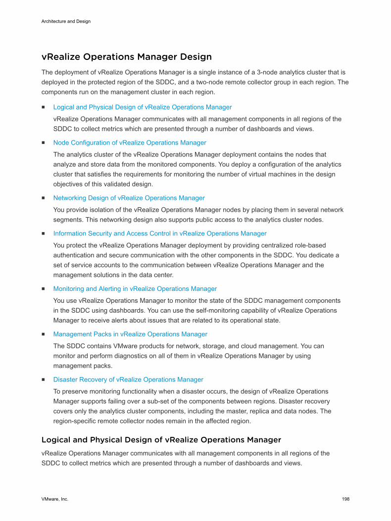
vRealize Operations Manager Design The deployment of vRealize Operations Manager is a single instance of a 3-node analytics cluster that isdeployed in the protected region of the SDDC, and a two-node remote collector group in each region. Thecomponents run on the management cluster in each region.
n Logical and Physical Design of vRealize Operations Manager
vRealize Operations Manager communicates with all management components in all regions of theSDDC to collect metrics which are presented through a number of dashboards and views.
n Node Configuration of vRealize Operations Manager
The analytics cluster of the vRealize Operations Manager deployment contains the nodes thatanalyze and store data from the monitored components. You deploy a configuration of the analyticscluster that satisfies the requirements for monitoring the number of virtual machines in the designobjectives of this validated design.
n Networking Design of vRealize Operations Manager
You provide isolation of the vRealize Operations Manager nodes by placing them in several networksegments. This networking design also supports public access to the analytics cluster nodes.
n Information Security and Access Control in vRealize Operations Manager
You protect the vRealize Operations Manager deployment by providing centralized role-basedauthentication and secure communication with the other components in the SDDC. You dedicate aset of service accounts to the communication between vRealize Operations Manager and themanagement solutions in the data center.
n Monitoring and Alerting in vRealize Operations Manager
You use vRealize Operations Manager to monitor the state of the SDDC management componentsin the SDDC using dashboards. You can use the self-monitoring capability of vRealize OperationsManager to receive alerts about issues that are related to its operational state.
n Management Packs in vRealize Operations Manager
The SDDC contains VMware products for network, storage, and cloud management. You canmonitor and perform diagnostics on all of them in vRealize Operations Manager by usingmanagement packs.
n Disaster Recovery of vRealize Operations Manager
To preserve monitoring functionality when a disaster occurs, the design of vRealize OperationsManager supports failing over a sub-set of the components between regions. Disaster recoverycovers only the analytics cluster components, including the master, replica and data nodes. Theregion-specific remote collector nodes remain in the affected region.
Logical and Physical Design of vRealize Operations Manager vRealize Operations Manager communicates with all management components in all regions of theSDDC to collect metrics which are presented through a number of dashboards and views.
Architecture and Design
VMware, Inc. 198
Logical Design
In a multi-region SDDC, you deploy a vRealize Operations Manager configuration that consists of thefollowing entities.
n 3-node (medium-size) vRealize Operations Manager analytics cluster that is highly available (HA).This topology provides high availability, scale-out capacity up to sixteen nodes, and failover.
n Group of 2 remote collector nodes in each region. The remote collectors communicate directly withthe data nodes in the vRealize Operations Manager analytics cluster. Use two remote collectors ineach region for load balancing and fault tolerance.
Each region contains its own pair of remote collectors whose role is to ease scalability by performing thedata collection from the applications that are not a subject to failover and periodically sending collecteddata to the analytics cluster. You fail over the analytics cluster only because the analytics cluster is theconstruct that analyzes and stores monitoring data.
This configuration supports failover of the analytics cluster by using Site Recovery Manager. In the eventof a disaster, Site Recovery Manager migrates the analytics cluster nodes to the failover region.
Architecture and Design
VMware, Inc. 199
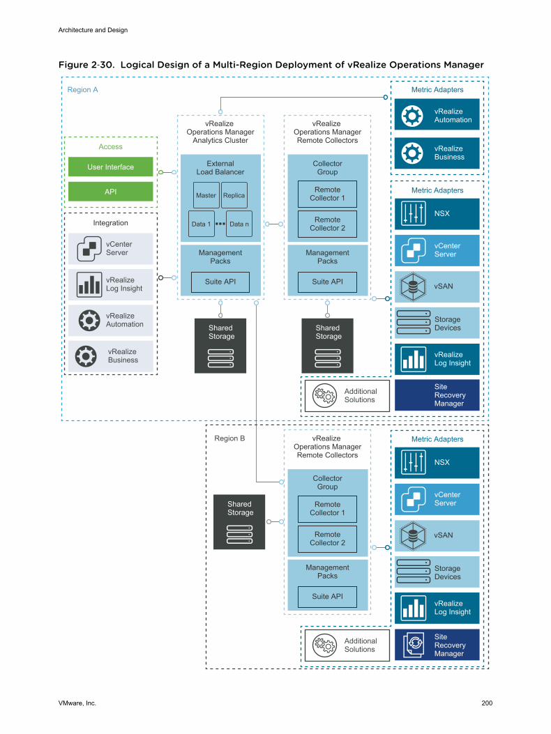
Figure 2‑30. Logical Design of a Multi-Region Deployment of vRealize Operations Manager
Metric AdaptersRegion A
Region B
vRealize Operations Manager
Analytics Cluster
Integration
ExternalLoad Balancer
vCenter Server
Access
User Interface
API
vRealizeLog Insight
vRealizeAutomation
Metric Adapters
vCenter Server
NSX
vRealizeLog Insight
AdditionalSolutions
vRealizeBusiness
vRealizeAutomation
ManagementPacks
Suite API
Shared Storage
vRealize Operations ManagerRemote Collectors
CollectorGroup
ManagementPacks
Suite API
Remote Collector 2
Remote Collector 1
Shared Storage
Metric Adapters
vCenter Server
NSX
vRealizeLog Insight
vRealize Operations ManagerRemote Collectors
CollectorGroup
ManagementPacks
Suite API
Remote Collector 2
Remote Collector 1
Shared Storage
StorageDevices
vSAN
StorageDevices
vSAN
Master Replica
Data 1 Data n
vRealizeBusiness
SiteRecoveryManager
AdditionalSolutions
SiteRecoveryManager
Architecture and Design
VMware, Inc. 200
Physical Design
The vRealize Operations Manager nodes run on the management cluster in each region of SDDC. Forinformation about the types of clusters, see Workload Domain Architecture.
Data Sources
vRealize Operations Manager collects data from the following virtual infrastructure and cloudmanagement components.
n Virtual Infrastructuren Platform Services Controller instances
n vCenter Server instances
n ESXi hosts
n NSX Manager instances
n NSX Controller instances
n NSX Edge instances
n Shared storage
n vRealize Automationn vRealize Automation Appliance
n vRealize IaaS Web Server
n vRealize IaaS Management Server
n vRealize IaaS DEM
n vRealize IaaS Proxy Agents
n Microsoft SQL Server
n vRealize Business for Cloudn vRealize Business Server
n vRealize Business Data Collectors
n vRealize Log Insight
n Site Recovery Manager
Node Configuration of vRealize Operations Manager The analytics cluster of the vRealize Operations Manager deployment contains the nodes that analyzeand store data from the monitored components. You deploy a configuration of the analytics cluster thatsatisfies the requirements for monitoring the number of virtual machines in the design objectives of thisvalidated design.
Deploy a 3-node vRealize Operations Manager analytics cluster in the cross-region application virtualnetwork. The analytics cluster consists of one master node, one master replica node, and one data nodeto enable scale out and high availability.
Architecture and Design
VMware, Inc. 201

Table 2‑132. Design Decisions on the Node Configuration of vRealize Operations Manager
Decision ID Design Decision Design Justification Design Implication
SDDC-OPS-MON-001
Deploy vRealize OperationsManager as a cluster ofthree nodes: one master,one master replica, and onedata node. Use thisdeployment to monitorRegion A and Region B.
n Provides the initial scalecapacity required formonitoring up to 1,000 VMs.
n Supports scale-up with moredata nodes.
n You must size identically allappliances which increases theresources requirements in the SDDC.
n You must manually install theadditional data nodes as per the datanode scale guidelines.
SDDC-OPS-MON-002
Deploy two remote collectornodes per region.
Removes the load from theanalytics cluster from collectingmetrics from applications that donot fail over between regions.
You must assign a collector group whenconfiguring the monitoring of a solution.
SDDC-OPS-MON-003
Apply vSphere DistributedResource Scheduler (DRS)anti-affinity rules to thevRealize OperationsManager analytics cluster.
Using vSphere DRS prevents thevRealize Operations Manageranalytics cluster nodes fromrunning on the same ESXi hostand risking the high availability ofthe cluster.
n You must perform additionalconfiguration to set up an anti-affinityrule.
n You can put in maintenance modeonly a single ESXi host at a time in amanagement cluster of four ESXihosts.
SDDC-OPS-MON-004
Apply vSphere DistributedResource Scheduler (DRS)anti-affinity rules to thevRealize OperationsManager remote collectorgroup.
Using vSphere DRS prevents thevRealize Operations Managerremote collector nodes fromrunning on the same ESXi hostand risking the high availability ofthe cluster.
n You must perform additionalconfiguration to set up an anti-affinityrule.
n You can put in maintenance modeonly a single ESXi host at a time in amanagement cluster of four ESXihosts.
Sizing Compute Resources for vRealize Operations Manager You size compute resources for vRealize Operations Manager to provide enough resources foraccommodating the analytics operations for monitoring the SDDC and the expected number of virtualmachines in the SDDC.
Size the vRealize Operations Manager analytics cluster according to VMware Knowledge Base article 2093783. vRealize Operations Manager is also sized so as to accommodate the SDDC design bydeploying a set of management packs. See Management Packs in vRealize Operations Manager
The sizing of the vRealize Operations Manager instance is calculated using the following two options:
Initial Setup Scaled-Out Setup
4 vCenter Server Appliances 4 vCenter Server Appliances
4 NSX Managers 4 NSX Managers
6 NSX Controllers 6 NSX Controllers
50 ESXi hosts 100 ESXi hosts
4 vSAN datastores 4 vSAN datastores
1,000 virtual machines 10,000 virtual machines
Architecture and Design
VMware, Inc. 202
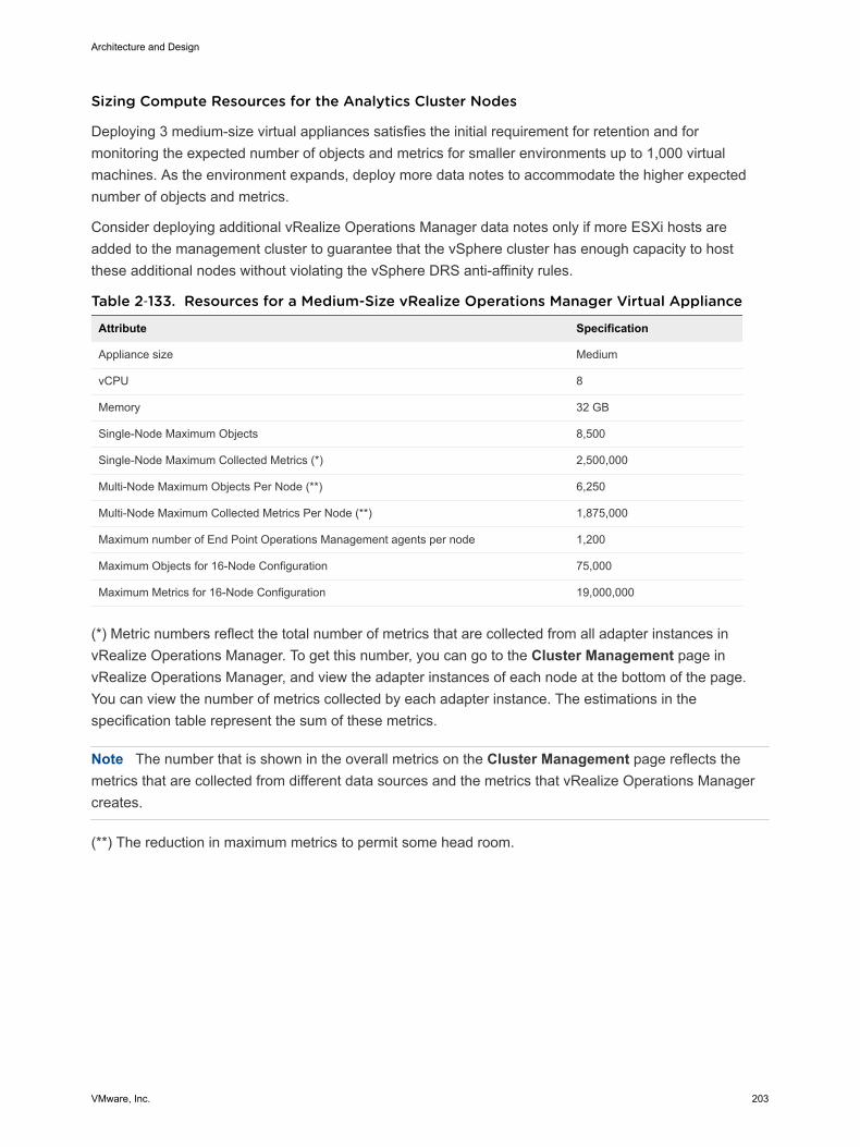
Sizing Compute Resources for the Analytics Cluster Nodes
Deploying 3 medium-size virtual appliances satisfies the initial requirement for retention and formonitoring the expected number of objects and metrics for smaller environments up to 1,000 virtualmachines. As the environment expands, deploy more data notes to accommodate the higher expectednumber of objects and metrics.
Consider deploying additional vRealize Operations Manager data notes only if more ESXi hosts areadded to the management cluster to guarantee that the vSphere cluster has enough capacity to hostthese additional nodes without violating the vSphere DRS anti-affinity rules.
Table 2‑133. Resources for a Medium-Size vRealize Operations Manager Virtual Appliance
Attribute Specification
Appliance size Medium
vCPU 8
Memory 32 GB
Single-Node Maximum Objects 8,500
Single-Node Maximum Collected Metrics (*) 2,500,000
Multi-Node Maximum Objects Per Node (**) 6,250
Multi-Node Maximum Collected Metrics Per Node (**) 1,875,000
Maximum number of End Point Operations Management agents per node 1,200
Maximum Objects for 16-Node Configuration 75,000
Maximum Metrics for 16-Node Configuration 19,000,000
(*) Metric numbers reflect the total number of metrics that are collected from all adapter instances invRealize Operations Manager. To get this number, you can go to the Cluster Management page invRealize Operations Manager, and view the adapter instances of each node at the bottom of the page.You can view the number of metrics collected by each adapter instance. The estimations in thespecification table represent the sum of these metrics.
Note The number that is shown in the overall metrics on the Cluster Management page reflects themetrics that are collected from different data sources and the metrics that vRealize Operations Managercreates.
(**) The reduction in maximum metrics to permit some head room.
Architecture and Design
VMware, Inc. 203
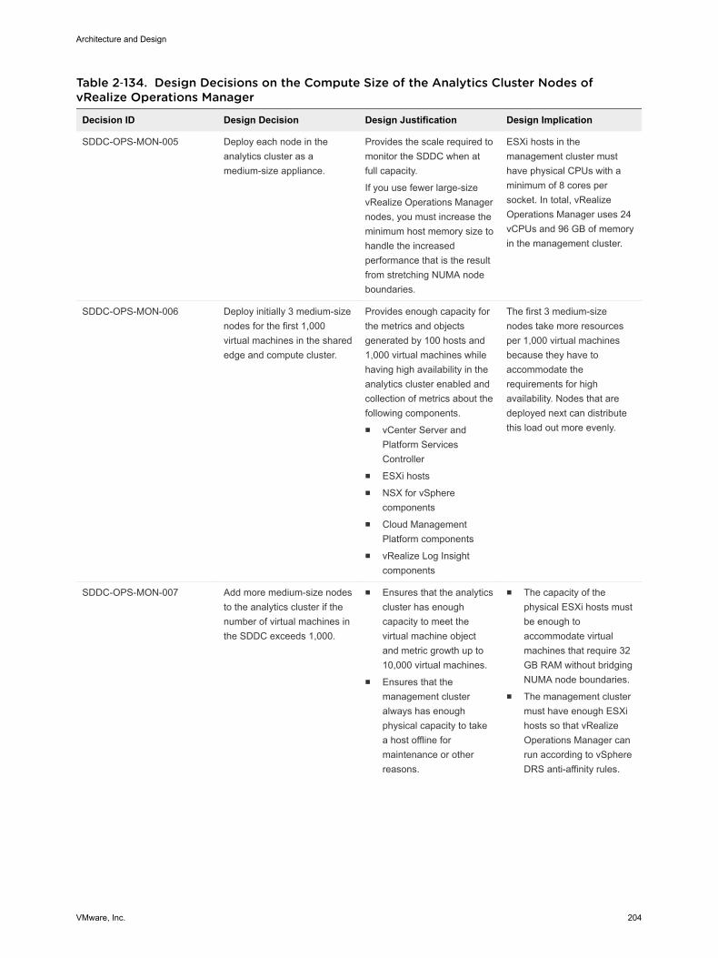
Table 2‑134. Design Decisions on the Compute Size of the Analytics Cluster Nodes ofvRealize Operations Manager
Decision ID Design Decision Design Justification Design Implication
SDDC-OPS-MON-005 Deploy each node in theanalytics cluster as amedium-size appliance.
Provides the scale required tomonitor the SDDC when atfull capacity.
If you use fewer large-sizevRealize Operations Managernodes, you must increase theminimum host memory size tohandle the increasedperformance that is the resultfrom stretching NUMA nodeboundaries.
ESXi hosts in themanagement cluster musthave physical CPUs with aminimum of 8 cores persocket. In total, vRealizeOperations Manager uses 24vCPUs and 96 GB of memoryin the management cluster.
SDDC-OPS-MON-006 Deploy initially 3 medium-sizenodes for the first 1,000virtual machines in the sharededge and compute cluster.
Provides enough capacity forthe metrics and objectsgenerated by 100 hosts and1,000 virtual machines whilehaving high availability in theanalytics cluster enabled andcollection of metrics about thefollowing components.n vCenter Server and
Platform ServicesController
n ESXi hostsn NSX for vSphere
componentsn Cloud Management
Platform componentsn vRealize Log Insight
components
The first 3 medium-sizenodes take more resourcesper 1,000 virtual machinesbecause they have toaccommodate therequirements for highavailability. Nodes that aredeployed next can distributethis load out more evenly.
SDDC-OPS-MON-007 Add more medium-size nodesto the analytics cluster if thenumber of virtual machines inthe SDDC exceeds 1,000.
n Ensures that the analyticscluster has enoughcapacity to meet thevirtual machine objectand metric growth up to10,000 virtual machines.
n Ensures that themanagement clusteralways has enoughphysical capacity to takea host offline formaintenance or otherreasons.
n The capacity of thephysical ESXi hosts mustbe enough toaccommodate virtualmachines that require 32GB RAM without bridgingNUMA node boundaries.
n The management clustermust have enough ESXihosts so that vRealizeOperations Manager canrun according to vSphereDRS anti-affinity rules.
Architecture and Design
VMware, Inc. 204

Table 2‑134. Design Decisions on the Compute Size of the Analytics Cluster Nodes ofvRealize Operations Manager (Continued)
Decision ID Design Decision Design Justification Design Implication
n The number of nodesmust not exceed numberof ESXi hosts in the
management cluster -
1.
For example, if themanagement clustercontains 6 ESXi hosts,you can deploy up to 5vRealize OperationsManager nodes in theanalytics cluster.
Sizing Compute Resources for the Remote Collector Nodes
Unlike the analytics cluster nodes, remote collector nodes have only the collector role. Deploying tworemote collector nodes in each region does not increase the capacity for monitored objects.
Table 2‑135. Size of a Standard Remote Collector Virtual Appliance for vRealize OperationsManager
Attribute Specification
Appliance size Remote Collector - Standard
vCPU 2
Memory 4 GB
Single-Node Maximum Objects 6,000
Single-Node Maximum Collected Metrics (*) 1,200,000
Multi-Node Maximum Objects Per Node N/A
Multi-Node Maximum Collected Metrics Per Node N/A
Maximum number of End Point Operations Management agents per node 250
Maximum Objects for 16-Node Configuration N/A
Maximum Metrics for 16-Node Configuration N/A
*The object limit for a remote collector is based on the VMware vCenter adapter.
Table 2‑136. Design Decisions on the Compute Size of the Remote Collector Nodes ofvRealize Operations Manager
Decision ID Design Decision Design Justification Design Implication
SDDC-OPS-MON-008 Deploy the standard-sizeremote collector virtualappliances.
Enables metric collection forthe expected number ofobjects in the SDDC when atfull capacity.
You must provide 4 vCPUsand 8 GB of memory in themanagement cluster in eachregion.
Architecture and Design
VMware, Inc. 205
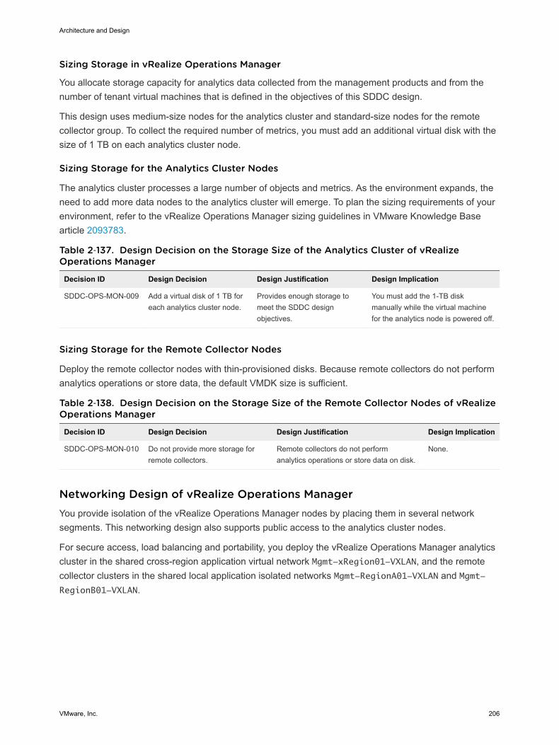
Sizing Storage in vRealize Operations Manager
You allocate storage capacity for analytics data collected from the management products and from thenumber of tenant virtual machines that is defined in the objectives of this SDDC design.
This design uses medium-size nodes for the analytics cluster and standard-size nodes for the remotecollector group. To collect the required number of metrics, you must add an additional virtual disk with thesize of 1 TB on each analytics cluster node.
Sizing Storage for the Analytics Cluster Nodes
The analytics cluster processes a large number of objects and metrics. As the environment expands, theneed to add more data nodes to the analytics cluster will emerge. To plan the sizing requirements of yourenvironment, refer to the vRealize Operations Manager sizing guidelines in VMware Knowledge Basearticle 2093783.
Table 2‑137. Design Decision on the Storage Size of the Analytics Cluster of vRealizeOperations Manager
Decision ID Design Decision Design Justification Design Implication
SDDC-OPS-MON-009 Add a virtual disk of 1 TB foreach analytics cluster node.
Provides enough storage tomeet the SDDC designobjectives.
You must add the 1-TB diskmanually while the virtual machinefor the analytics node is powered off.
Sizing Storage for the Remote Collector Nodes
Deploy the remote collector nodes with thin-provisioned disks. Because remote collectors do not performanalytics operations or store data, the default VMDK size is sufficient.
Table 2‑138. Design Decision on the Storage Size of the Remote Collector Nodes of vRealizeOperations Manager
Decision ID Design Decision Design Justification Design Implication
SDDC-OPS-MON-010 Do not provide more storage forremote collectors.
Remote collectors do not performanalytics operations or store data on disk.
None.
Networking Design of vRealize Operations Manager You provide isolation of the vRealize Operations Manager nodes by placing them in several networksegments. This networking design also supports public access to the analytics cluster nodes.
For secure access, load balancing and portability, you deploy the vRealize Operations Manager analyticscluster in the shared cross-region application virtual network Mgmt-xRegion01-VXLAN, and the remotecollector clusters in the shared local application isolated networks Mgmt-RegionA01-VXLAN and Mgmt-RegionB01-VXLAN.
Architecture and Design
VMware, Inc. 206

Figure 2‑31. Networking Design of the vRealize Operations Manager Deployment
APP
OSAPP
OSAPP
OSAPP
OS
APP
OSAPP
OSAPP
OSAPP
OSAPP
OSAPP
OS
Universal Distributed Logical Router
DataCenterUser
ActiveDirectory
Internet/EnterpriseNetwork
Region A(SF001 - San Francisco)
Management vCenter Serverlax01m01vc01.lax01.rainpole.
local
Compute vCenter Serverlax01w01vc01.lax01.rainpole.
local
sfo01vropsc01a sfo01vropsc01b
Mgmt-RegionA01-VXLAN
VLAN: sfo01-m01-vds01-management
172.16.11.0/24
VLAN: lax01-m01-vds01-management.
172.17.11.0/24
Management vCenter Server
sfo01m01vc01.sfo01.rainpole.
local
Compute vCenter Serversfo01w01vc01.sfo01.rainpole.
local
PhysicalUpstream
Router
vrops01svr01a vrops01svr01b vrops01svr01c
192.168.11.0/24
Mgmt-xRegion01-VXLAN
VIP: vrops01svr01.rainpole.local
Analytics Cluster Region A
192.168.31.0/24
Remote Collectors Region A
Region B(LAX01 - Los Angeles)
PhysicalUpstream
Router
lax01vropsc01a lax01vropsc01b
Mgmt-RegionB01-VXLAN
192.168.32.0/24
Remote Collectors
Region B
vrops01svr01a vrops01svr01b vrops01svr01c
192.168.11.0/24
VIP: vrops01svr01.rainpole.local
Placeholder Disaster RecoveryAnalytics Cluster
Region B
sfo01m01lb01 lax01m01lb01
Mgmt-xRegion01-VXLAN
NSX EdgeLoad
Balancer
NSX EdgeLoadBalancer
Architecture and Design
VMware, Inc. 207
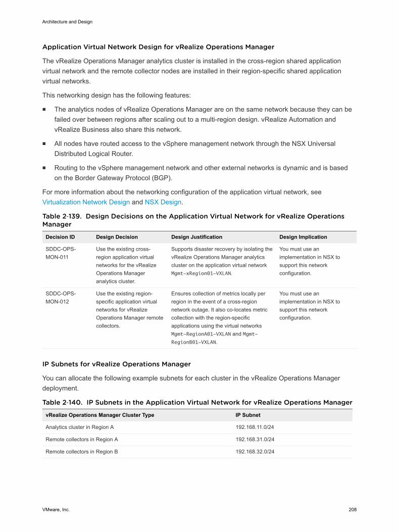
Application Virtual Network Design for vRealize Operations Manager
The vRealize Operations Manager analytics cluster is installed in the cross-region shared applicationvirtual network and the remote collector nodes are installed in their region-specific shared applicationvirtual networks.
This networking design has the following features:
n The analytics nodes of vRealize Operations Manager are on the same network because they can befailed over between regions after scaling out to a multi-region design. vRealize Automation andvRealize Business also share this network.
n All nodes have routed access to the vSphere management network through the NSX UniversalDistributed Logical Router.
n Routing to the vSphere management network and other external networks is dynamic and is basedon the Border Gateway Protocol (BGP).
For more information about the networking configuration of the application virtual network, see Virtualization Network Design and NSX Design.
Table 2‑139. Design Decisions on the Application Virtual Network for vRealize OperationsManager
Decision ID Design Decision Design Justification Design Implication
SDDC-OPS-MON-011
Use the existing cross-region application virtualnetworks for the vRealizeOperations Manageranalytics cluster.
Supports disaster recovery by isolating thevRealize Operations Manager analyticscluster on the application virtual networkMgmt-xRegion01-VXLAN.
You must use animplementation in NSX tosupport this networkconfiguration.
SDDC-OPS-MON-012
Use the existing region-specific application virtualnetworks for vRealizeOperations Manager remotecollectors.
Ensures collection of metrics locally perregion in the event of a cross-regionnetwork outage. It also co-locates metriccollection with the region-specificapplications using the virtual networksMgmt-RegionA01-VXLAN and Mgmt-RegionB01-VXLAN.
You must use animplementation in NSX tosupport this networkconfiguration.
IP Subnets for vRealize Operations Manager
You can allocate the following example subnets for each cluster in the vRealize Operations Managerdeployment.
Table 2‑140. IP Subnets in the Application Virtual Network for vRealize Operations Manager
vRealize Operations Manager Cluster Type IP Subnet
Analytics cluster in Region A 192.168.11.0/24
Remote collectors in Region A 192.168.31.0/24
Remote collectors in Region B 192.168.32.0/24
Architecture and Design
VMware, Inc. 208
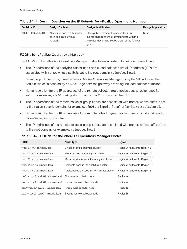
Table 2‑141. Design Decision on the IP Subnets for vRealize Operations Manager
Decision ID Design Decision Design Justification Design Implication
SDDC-OPS-MON-013 Allocate separate subnets foreach application virtualnetwork.
Placing the remote collectors on their ownsubnet enables them to communicate with theanalytics cluster and not be a part of the failovergroup.
None.
FQDNs for vRealize Operations Manager
The FQDNs of the vRealize Operations Manager nodes follow a certain domain name resolution:
n The IP addresses of the analytics cluster node and a load balancer virtual IP address (VIP) areassociated with names whose suffix is set to the root domain rainpole.local.
From the public network, users access vRealize Operations Manager using the VIP address, thetraffic to which is handled by an NSX Edge services gateway providing the load balancer function.
n Name resolution for the IP addresses of the remote collector group nodes uses a region-specificsuffix, for example, sfo01.rainpole.local or lax01.rainpole.local.
n The IP addresses of the remote collector group nodes are associated with names whose suffix is setto the region-specific domain, for example, sfo01.rainpole.local or lax01.rainpole.local.
n Name resolution for the IP addresses of the remote collector group nodes uses a root domain suffix,for example, rainpole.local
n The IP addresses of the remote collector group nodes are associated with names whose suffix is setto the root domain, for example, rainpole.local
Table 2‑142. FQDNs for the vRealize Operations Manager Nodes
FQDN Node Type Region
vrops01svr01.rainpole.local Virtual IP of the analytics cluster Region A (failover to Region B)
vrops01svr01a.rainpole.local Master node in the analytics cluster Region A (failover to Region B)
vrops01svr01b.rainpole.local Master replica node in the analytics cluster Region A (failover to Region B)
vrops01svr01c.rainpole.local First data node in the analytics cluster Region A (failover to Region B)
vrops01svr01x.rainpole.local Additional data nodes in the analytics cluster Region A (failover to Region B)
sfo01vropsc01a.sfo01.rainpole.local First remote collector node Region A
sfo01vropsc01b.sfo01.rainpole.local Second remote collector node Region A
lax01vropsc01a.lax01.rainpole.local First remote collector node Region B
lax01vropsc01b.lax01.rainpole.local Second remote collector node Region B
Architecture and Design
VMware, Inc. 209
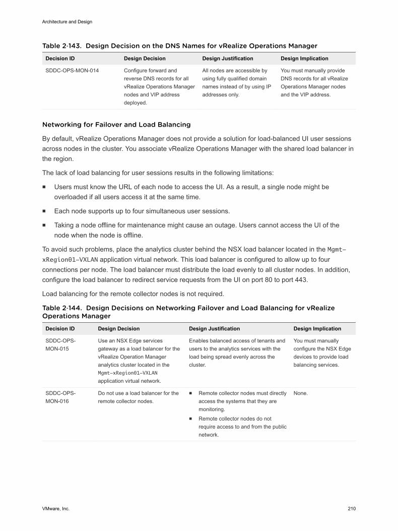
Table 2‑143. Design Decision on the DNS Names for vRealize Operations Manager
Decision ID Design Decision Design Justification Design Implication
SDDC-OPS-MON-014 Configure forward andreverse DNS records for allvRealize Operations Managernodes and VIP addressdeployed.
All nodes are accessible byusing fully qualified domainnames instead of by using IPaddresses only.
You must manually provideDNS records for all vRealizeOperations Manager nodesand the VIP address.
Networking for Failover and Load Balancing
By default, vRealize Operations Manager does not provide a solution for load-balanced UI user sessionsacross nodes in the cluster. You associate vRealize Operations Manager with the shared load balancer inthe region.
The lack of load balancing for user sessions results in the following limitations:
n Users must know the URL of each node to access the UI. As a result, a single node might beoverloaded if all users access it at the same time.
n Each node supports up to four simultaneous user sessions.
n Taking a node offline for maintenance might cause an outage. Users cannot access the UI of thenode when the node is offline.
To avoid such problems, place the analytics cluster behind the NSX load balancer located in the Mgmt-xRegion01-VXLAN application virtual network. This load balancer is configured to allow up to fourconnections per node. The load balancer must distribute the load evenly to all cluster nodes. In addition,configure the load balancer to redirect service requests from the UI on port 80 to port 443.
Load balancing for the remote collector nodes is not required.
Table 2‑144. Design Decisions on Networking Failover and Load Balancing for vRealizeOperations Manager
Decision ID Design Decision Design Justification Design Implication
SDDC-OPS-MON-015
Use an NSX Edge servicesgateway as a load balancer for thevRealize Operation Manageranalytics cluster located in theMgmt-xRegion01-VXLAN
application virtual network.
Enables balanced access of tenants andusers to the analytics services with theload being spread evenly across thecluster.
You must manuallyconfigure the NSX Edgedevices to provide loadbalancing services.
SDDC-OPS-MON-016
Do not use a load balancer for theremote collector nodes.
n Remote collector nodes must directlyaccess the systems that they aremonitoring.
n Remote collector nodes do notrequire access to and from the publicnetwork.
None.
Architecture and Design
VMware, Inc. 210
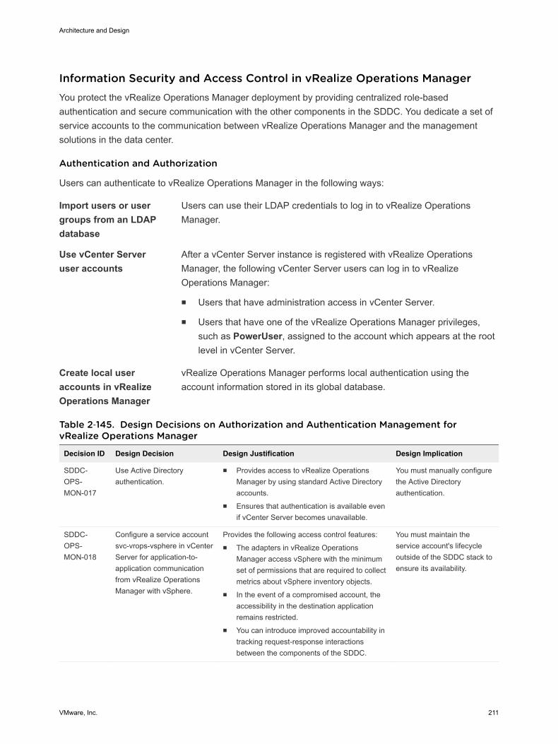
Information Security and Access Control in vRealize Operations Manager You protect the vRealize Operations Manager deployment by providing centralized role-basedauthentication and secure communication with the other components in the SDDC. You dedicate a set ofservice accounts to the communication between vRealize Operations Manager and the managementsolutions in the data center.
Authentication and Authorization
Users can authenticate to vRealize Operations Manager in the following ways:
Import users or usergroups from an LDAPdatabase
Users can use their LDAP credentials to log in to vRealize OperationsManager.
Use vCenter Serveruser accounts
After a vCenter Server instance is registered with vRealize OperationsManager, the following vCenter Server users can log in to vRealizeOperations Manager:
n Users that have administration access in vCenter Server.
n Users that have one of the vRealize Operations Manager privileges,such as PowerUser, assigned to the account which appears at the rootlevel in vCenter Server.
Create local useraccounts in vRealizeOperations Manager
vRealize Operations Manager performs local authentication using theaccount information stored in its global database.
Table 2‑145. Design Decisions on Authorization and Authentication Management forvRealize Operations Manager
Decision ID Design Decision Design Justification Design Implication
SDDC-OPS-MON-017
Use Active Directoryauthentication.
n Provides access to vRealize OperationsManager by using standard Active Directoryaccounts.
n Ensures that authentication is available evenif vCenter Server becomes unavailable.
You must manually configurethe Active Directoryauthentication.
SDDC-OPS-MON-018
Configure a service accountsvc-vrops-vsphere in vCenterServer for application-to-application communicationfrom vRealize OperationsManager with vSphere.
Provides the following access control features:n The adapters in vRealize Operations
Manager access vSphere with the minimumset of permissions that are required to collectmetrics about vSphere inventory objects.
n In the event of a compromised account, theaccessibility in the destination applicationremains restricted.
n You can introduce improved accountability intracking request-response interactionsbetween the components of the SDDC.
You must maintain theservice account's lifecycleoutside of the SDDC stack toensure its availability.
Architecture and Design
VMware, Inc. 211
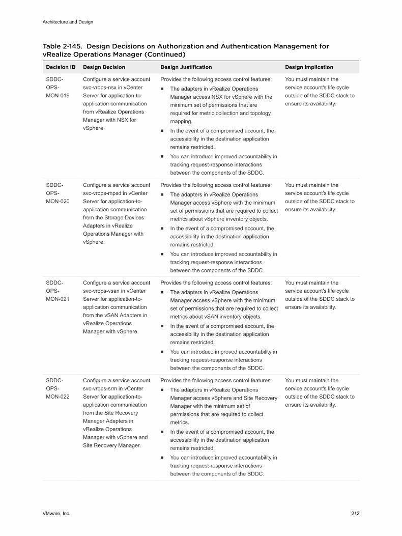
Table 2‑145. Design Decisions on Authorization and Authentication Management forvRealize Operations Manager (Continued)
Decision ID Design Decision Design Justification Design Implication
SDDC-OPS-MON-019
Configure a service accountsvc-vrops-nsx in vCenterServer for application-to-application communicationfrom vRealize OperationsManager with NSX forvSphere
Provides the following access control features:n The adapters in vRealize Operations
Manager access NSX for vSphere with theminimum set of permissions that arerequired for metric collection and topologymapping.
n In the event of a compromised account, theaccessibility in the destination applicationremains restricted.
n You can introduce improved accountability intracking request-response interactionsbetween the components of the SDDC.
You must maintain theservice account's life cycleoutside of the SDDC stack toensure its availability.
SDDC-OPS-MON-020
Configure a service accountsvc-vrops-mpsd in vCenterServer for application-to-application communicationfrom the Storage DevicesAdapters in vRealizeOperations Manager withvSphere.
Provides the following access control features:n The adapters in vRealize Operations
Manager access vSphere with the minimumset of permissions that are required to collectmetrics about vSphere inventory objects.
n In the event of a compromised account, theaccessibility in the destination applicationremains restricted.
n You can introduce improved accountability intracking request-response interactionsbetween the components of the SDDC.
You must maintain theservice account's life cycleoutside of the SDDC stack toensure its availability.
SDDC-OPS-MON-021
Configure a service accountsvc-vrops-vsan in vCenterServer for application-to-application communicationfrom the vSAN Adapters invRealize OperationsManager with vSphere.
Provides the following access control features:n The adapters in vRealize Operations
Manager access vSphere with the minimumset of permissions that are required to collectmetrics about vSAN inventory objects.
n In the event of a compromised account, theaccessibility in the destination applicationremains restricted.
n You can introduce improved accountability intracking request-response interactionsbetween the components of the SDDC.
You must maintain theservice account's life cycleoutside of the SDDC stack toensure its availability.
SDDC-OPS-MON-022
Configure a service accountsvc-vrops-srm in vCenterServer for application-to-application communicationfrom the Site RecoveryManager Adapters invRealize OperationsManager with vSphere andSite Recovery Manager.
Provides the following access control features:n The adapters in vRealize Operations
Manager access vSphere and Site RecoveryManager with the minimum set ofpermissions that are required to collectmetrics.
n In the event of a compromised account, theaccessibility in the destination applicationremains restricted.
n You can introduce improved accountability intracking request-response interactionsbetween the components of the SDDC.
You must maintain theservice account's life cycleoutside of the SDDC stack toensure its availability.
Architecture and Design
VMware, Inc. 212
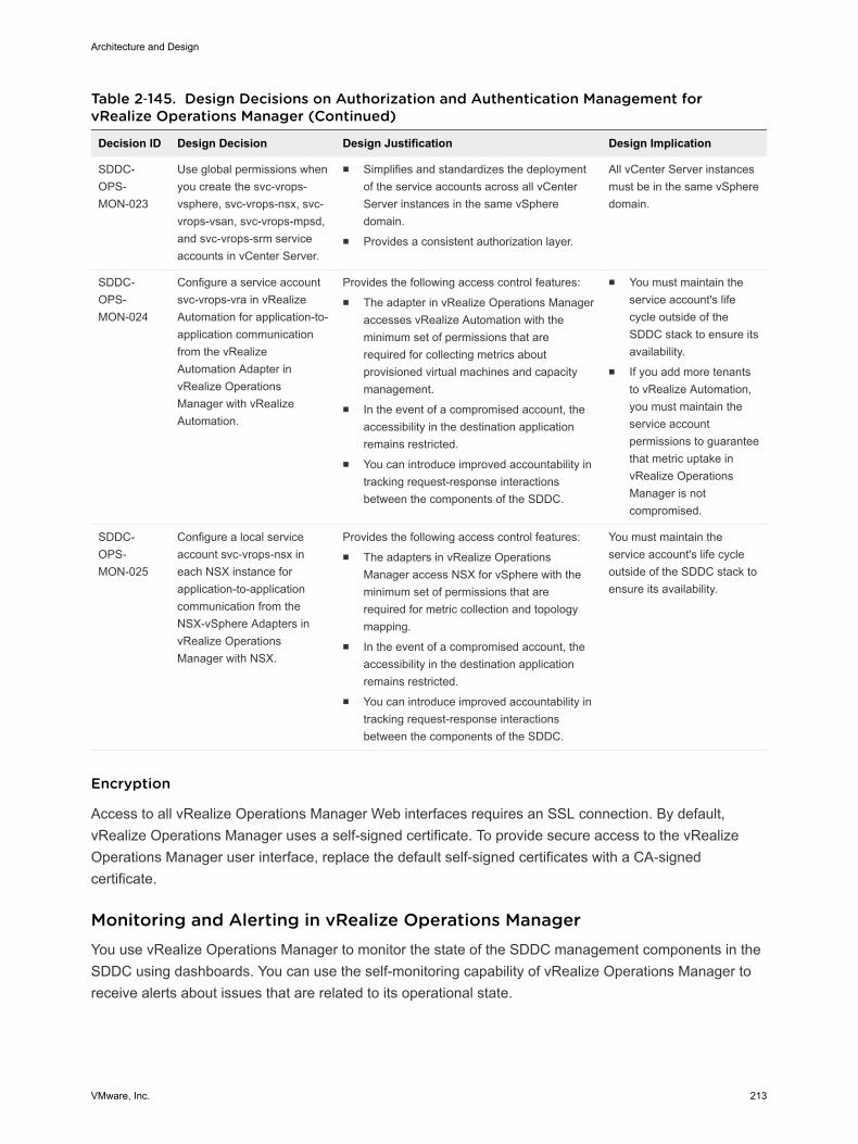
Table 2‑145. Design Decisions on Authorization and Authentication Management forvRealize Operations Manager (Continued)
Decision ID Design Decision Design Justification Design Implication
SDDC-OPS-MON-023
Use global permissions whenyou create the svc-vrops-vsphere, svc-vrops-nsx, svc-vrops-vsan, svc-vrops-mpsd,and svc-vrops-srm serviceaccounts in vCenter Server.
n Simplifies and standardizes the deploymentof the service accounts across all vCenterServer instances in the same vSpheredomain.
n Provides a consistent authorization layer.
All vCenter Server instancesmust be in the same vSpheredomain.
SDDC-OPS-MON-024
Configure a service accountsvc-vrops-vra in vRealizeAutomation for application-to-application communicationfrom the vRealizeAutomation Adapter invRealize OperationsManager with vRealizeAutomation.
Provides the following access control features:n The adapter in vRealize Operations Manager
accesses vRealize Automation with theminimum set of permissions that arerequired for collecting metrics aboutprovisioned virtual machines and capacitymanagement.
n In the event of a compromised account, theaccessibility in the destination applicationremains restricted.
n You can introduce improved accountability intracking request-response interactionsbetween the components of the SDDC.
n You must maintain theservice account's lifecycle outside of theSDDC stack to ensure itsavailability.
n If you add more tenantsto vRealize Automation,you must maintain theservice accountpermissions to guaranteethat metric uptake invRealize OperationsManager is notcompromised.
SDDC-OPS-MON-025
Configure a local serviceaccount svc-vrops-nsx ineach NSX instance forapplication-to-applicationcommunication from theNSX-vSphere Adapters invRealize OperationsManager with NSX.
Provides the following access control features:n The adapters in vRealize Operations
Manager access NSX for vSphere with theminimum set of permissions that arerequired for metric collection and topologymapping.
n In the event of a compromised account, theaccessibility in the destination applicationremains restricted.
n You can introduce improved accountability intracking request-response interactionsbetween the components of the SDDC.
You must maintain theservice account's life cycleoutside of the SDDC stack toensure its availability.
Encryption
Access to all vRealize Operations Manager Web interfaces requires an SSL connection. By default,vRealize Operations Manager uses a self-signed certificate. To provide secure access to the vRealizeOperations Manager user interface, replace the default self-signed certificates with a CA-signedcertificate.
Monitoring and Alerting in vRealize Operations Manager You use vRealize Operations Manager to monitor the state of the SDDC management components in theSDDC using dashboards. You can use the self-monitoring capability of vRealize Operations Manager toreceive alerts about issues that are related to its operational state.
Architecture and Design
VMware, Inc. 213
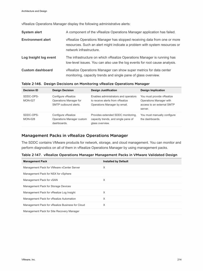
vRealize Operations Manager display the following administrative alerts:
System alert A component of the vRealize Operations Manager application has failed.
Environment alert vRealize Operations Manager has stopped receiving data from one or moreresources. Such an alert might indicate a problem with system resources ornetwork infrastructure.
Log Insight log event The infrastructure on which vRealize Operations Manager is running haslow-level issues. You can also use the log events for root cause analysis.
Custom dashboard vRealize Operations Manager can show super metrics for data centermonitoring, capacity trends and single pane of glass overview.
Table 2‑146. Design Decisions on Monitoring vRealize Operations Manager
Decision ID Design Decision Design Justification Design Implication
SDDC-OPS-MON-027
Configure vRealizeOperations Manager forSMTP outbound alerts.
Enables administrators and operatorsto receive alerts from vRealizeOperations Manager by email.
You must provide vRealizeOperations Manager withaccess to an external SMTPserver.
SDDC-OPS-MON-028
Configure vRealizeOperations Manager customdashboards.
Provides extended SDDC monitoring,capacity trends, and single pane ofglass overview.
You must manually configurethe dashboards.
Management Packs in vRealize Operations Manager The SDDC contains VMware products for network, storage, and cloud management. You can monitor andperform diagnostics on all of them in vRealize Operations Manager by using management packs.
Table 2‑147. vRealize Operations Manager Management Packs in VMware Validated Design
Management Pack Installed by Default
Management Pack for VMware vCenter Server X
Management Pack for NSX for vSphere
Management Pack for vSAN X
Management Pack for Storage Devices
Management Pack for vRealize Log Insight X
Management Pack for vRealize Automation X
Management Pack for vRealize Business for Cloud X
Management Pack for Site Recovery Manager
Architecture and Design
VMware, Inc. 214
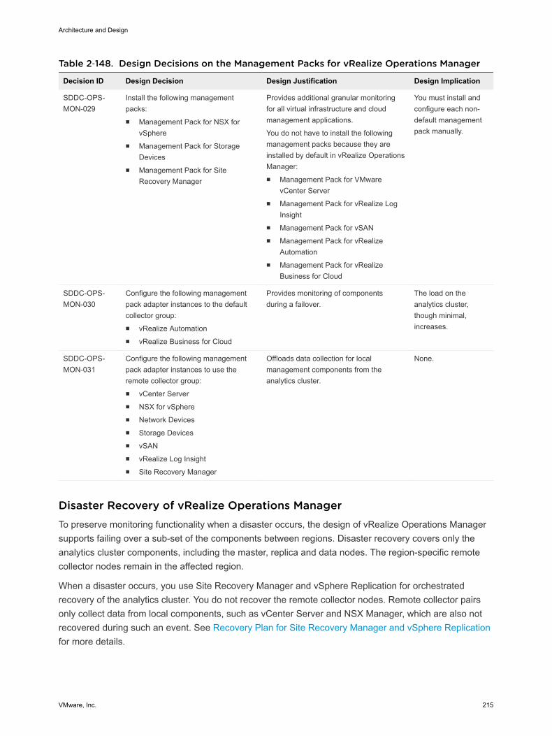
Table 2‑148. Design Decisions on the Management Packs for vRealize Operations Manager
Decision ID Design Decision Design Justification Design Implication
SDDC-OPS-MON-029
Install the following managementpacks:n Management Pack for NSX for
vSpheren Management Pack for Storage
Devicesn Management Pack for Site
Recovery Manager
Provides additional granular monitoringfor all virtual infrastructure and cloudmanagement applications.
You do not have to install the followingmanagement packs because they areinstalled by default in vRealize OperationsManager:n Management Pack for VMware
vCenter Servern Management Pack for vRealize Log
Insightn Management Pack for vSANn Management Pack for vRealize
Automationn Management Pack for vRealize
Business for Cloud
You must install andconfigure each non-default managementpack manually.
SDDC-OPS-MON-030
Configure the following managementpack adapter instances to the defaultcollector group:n vRealize Automationn vRealize Business for Cloud
Provides monitoring of componentsduring a failover.
The load on theanalytics cluster,though minimal,increases.
SDDC-OPS-MON-031
Configure the following managementpack adapter instances to use theremote collector group:n vCenter Servern NSX for vSpheren Network Devicesn Storage Devicesn vSANn vRealize Log Insightn Site Recovery Manager
Offloads data collection for localmanagement components from theanalytics cluster.
None.
Disaster Recovery of vRealize Operations ManagerTo preserve monitoring functionality when a disaster occurs, the design of vRealize Operations Managersupports failing over a sub-set of the components between regions. Disaster recovery covers only theanalytics cluster components, including the master, replica and data nodes. The region-specific remotecollector nodes remain in the affected region.
When a disaster occurs, you use Site Recovery Manager and vSphere Replication for orchestratedrecovery of the analytics cluster. You do not recover the remote collector nodes. Remote collector pairsonly collect data from local components, such as vCenter Server and NSX Manager, which are also notrecovered during such an event. See Recovery Plan for Site Recovery Manager and vSphere Replicationfor more details.
Architecture and Design
VMware, Inc. 215
vRealize Log Insight Design vRealize Log Insight design enables real-time logging for all components that build up the managementcapabilities of the SDDC.
Logical Design and Data Sources of vRealize Log Insight vRealize Log Insight collects log events from all management components in each region of the SDDC.
Logical Design
In a multi-region Software-Defined Data Center, deploy a vRealize Log Insight cluster that consists ofthree nodes in each region. This configuration provides continued availability and increased log ingestionrates.
Architecture and Design
VMware, Inc. 216

Figure 2‑32. Logical Design of vRealize Log Insight
Region A
EventForwarding
Integration
IntegratedLoad Balancer
vSphere
Access
User Interface
API
vRealizeOperationsManager
Content Packs
Syslog
Ingestion API
IntegratedLoad Balancer
Content Packs
Syslog
Ingestion API
Shared Storage
LogArchive
NFSExport
Region B
vRealize Log Insight
vRealize Log Insight
Integration
vSphere
Access
User Interface
API
vRealizeOperationsManager
Logging Clients
vCenter Server
ESXi
NSX
vRealizeAutomation
AdditionalSolutions
Shared Storage
LogArchive
NFSExport
Master Worker1
Worker2 WorkerN
Master Worker1
Worker2 WorkerN
SiteRecoveryManager
vRealizeOperationsManager
Logging Clients
vCenter Server
ESXi
NSX
vRealizeAutomation
AdditionalSolutions
SiteRecoveryManager
Sources of Log Data
vRealize Log Insight collects logs as to provide monitoring information about the SDDC from a centrallocation.
vRealize Log Insight collects log events from the following virtual infrastructure and cloud managementcomponents.
n Management cluster
n Platform Services Controller
n vCenter Server
n Site Recovery Manager
Architecture and Design
VMware, Inc. 217
n ESXi hosts
n Shared edge and compute cluster
n Platform Services Controller
n vCenter Server
n ESXi hosts
n NSX for vSphere for the management cluster and for the shared compute and edge cluster
n NSX Manager instances
n NSX Controller instances
n NSX Edge services gateway instances NSX distributed logical router instances
n NSX universal distributed logical router instances
n NSX distributed firewall ESXi kernel module
n vRealize Lifecycle Manager
n vRealize Automation
n vRealize Automation Appliance
n vRealize Orchestrator (embedded in the vRealize Automation Appliance)
n vRealize IaaS Web Server
n vRealize IaaS Management Server
n vRealize IaaS DEM
n vRealize IaaS Proxy Agents
n Microsoft SQL Server
n vRealize Business
n vRealize Business server
n vRealize Business data collector
n vRealize Operations Manager
n Analytics cluster nodes
n Remote collectors
n vRealize Log Insight instance in the other region as a result of event forwarding
Node Configuration of vRealize Log Insight The vRealize Log Insight cluster consists of one master node and two worker nodes behind a loadbalancer.
Architecture and Design
VMware, Inc. 218
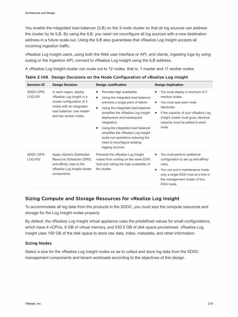
You enable the integrated load balancer (ILB) on the 3-node cluster so that all log sources can addressthe cluster by its ILB. By using the ILB, you need not reconfigure all log sources with a new destinationaddress in a future scale-out. Using the ILB also guarantees that vRealize Log Insight accepts allincoming ingestion traffic.
vRealize Log Insight users, using both the Web user interface or API, and clients, ingesting logs by usingsyslog or the Ingestion API, connect to vRealize Log Insight using the ILB address.
A vRealize Log Insight cluster can scale out to 12 nodes, that is, 1 master and 11 worker nodes.
Table 2‑149. Design Decisions on the Node Configuration of vRealize Log Insight
Decision ID Design Decision Design Justification Design Implication
SDDC-OPS-LOG-001
In each region, deployvRealize Log Insight in acluster configuration of 3nodes with an integratedload balancer: one masterand two worker nodes.
n Provides high availability.n Using the integrated load balancer
prevents a single point of failure.n Using the integrated load balancer
simplifies the vRealize Log Insightdeployment and subsequentintegration.
n Using the integrated load balancersimplifies the vRealize Log Insightscale-out operations reducing theneed to reconfigure existinglogging sources.
n You must deploy a minimum of 3medium nodes.
n You must size each nodeidentically.
n If the capacity of your vRealize LogInsight cluster must grow, identicalcapacity must be added to eachnode.
SDDC-OPS-LOG-002
Apply vSphere DistributedResource Scheduler (DRS)anti-affinity rules to thevRealize Log Insight clustercomponents.
Prevents the vRealize Log Insightnodes from running on the same ESXihost and risking the high availability ofthe cluster.
n You must perform additionalconfiguration to set up anti-affinityrules.
n You can put in maintenance modeonly a single ESXi host at a time inthe management cluster of fourESXi hosts.
Sizing Compute and Storage Resources for vRealize Log Insight To accommodate all log data from the products in the SDDC, you must size the compute resources andstorage for the Log Insight nodes properly.
By default, the vRealize Log Insight virtual appliance uses the predefined values for small configurations,which have 4 vCPUs, 8 GB of virtual memory, and 530.5 GB of disk space provisioned. vRealize LogInsight uses 100 GB of the disk space to store raw data, index, metadata, and other information.
Sizing Nodes
Select a size for the vRealize Log Insight nodes so as to collect and store log data from the SDDCmanagement components and tenant workloads according to the objectives of this design.
Architecture and Design
VMware, Inc. 219
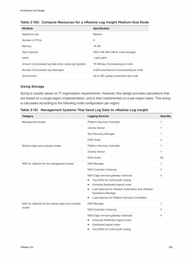
Table 2‑150. Compute Resources for a vRealize Log Insight Medium-Size Node
Attribute Specification
Appliance size Medium
Number of CPUs 8
Memory 16 GB
Disk Capacity 530.5 GB (490 GB for event storage)
IOPS 1,000 IOPS
Amount of processed log data when using log ingestion 75 GB/day of processing per node
Number of processed log messages 5,000 event/second of processing per node
Environment Up to 250 syslog connections per node
Sizing Storage
Sizing is usually based on IT organization requirements. However, this design provides calculations thatare based on a single-region implementation, and is then implemented on a per-region basis. This sizingis calculated according to the following node configuration per region:
Table 2‑151. Management Systems That Send Log Data to vRealize Log Insight
Category Logging Sources Quantity
Management cluster Platform Services Controller 1
vCenter Server 1
Site Recovery Manager 1
ESXi Hosts 4
Shared edge and compute cluster Platform Services Controller 1
vCenter Server 1
ESXi Hosts 64
NSX for vSphere for the management cluster NSX Manager 1
NSX Controller Instances 3
NSX Edge services gateway instances:n Two ESGs for north-south routingn Universal distributed logical routern Load balancer for vRealize Automation and vRealize
Operations Managern Load balancer for Platform Services Controllers
5
NSX for vSphere for the shared edge and computecluster
NSX Manager 1
NSX Controller Instances 3
NSX Edge services gateway instances:n Universal distributed logical routern Distributed logical routern Two ESGs for north-south routing
4
Architecture and Design
VMware, Inc. 220
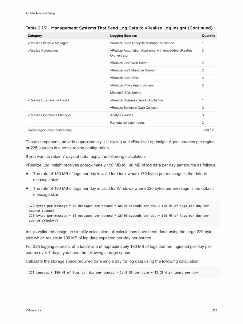
Table 2‑151. Management Systems That Send Log Data to vRealize Log Insight (Continued)
Category Logging Sources Quantity
vRealize Lifecycle Manager vRealize Suite Lifecycle Manager Appliance 1
vRealize Automation vRealize Automation Appliance with embedded vRealizeOrchestrator
3
vRealize IaaS Web Server 2
vRealize IaaS Manager Server 2
vRealize IaaS DEM 2
vRealize Proxy Agent Servers 2
Microsoft SQL Server 1
vRealize Business for Cloud vRealize Business Server Appliance 1
vRealize Business Data Collector 2
vRealize Operations Manager Analytics nodes 3
Remote collector nodes 2
Cross-region event forwarding Total * 2
These components provide approximately 111 syslog and vRealize Log Insight Agent sources per region,or 225 sources in a cross-region configuration.
If you want to retain 7 days of data, apply the following calculation:
vRealize Log Insight receives approximately 150 MB to 190 MB of log data per day per source as follows.
n The rate of 150 MB of logs per day is valid for Linux where 170 bytes per message is the defaultmessage size.
n The rate of 190 MB of logs per day is valid for Windows where 220 bytes per message is the defaultmessage size.
170 bytes per message * 10 messages per second * 86400 seconds per day = 150 MB of logs per day per
source (Linux)
220 bytes per message * 10 messages per second * 86400 seconds per day = 190 MB of logs per day per
source (Windows)
In this validated design, to simplify calculation, all calculations have been done using the large 220 bytesize which results in 190 MB of log data expected per-day per-source.
For 225 logging sources, at a basal rate of approximately 190 MB of logs that are ingested per-day per-source over 7 days, you need the following storage space:
Calculate the storage space required for a single day for log data using the following calculation:
225 sources * 190 MB of logs per day per source * 1e-9 GB per byte ≈ 42 GB disk space per day
Architecture and Design
VMware, Inc. 221
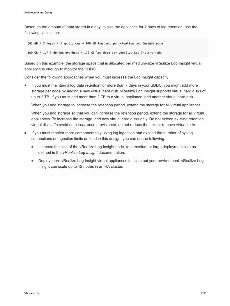
Based on the amount of data stored in a day, to size the appliance for 7 days of log retention, use thefollowing calculation:
(42 GB * 7 days) / 3 аppliances ≈ 100 GB log data per vRealize Log Insight node
100 GB * 1.7 indexing overhead ≈ 170 GB log data per vRealize Log Insight node
Based on this example, the storage space that is allocated per medium-size vRealize Log Insight virtualappliance is enough to monitor the SDDC.
Consider the following approaches when you must increase the Log Insight capacity:
n If you must maintain a log data retention for more than 7 days in your SDDC, you might add morestorage per node by adding a new virtual hard disk. vRealize Log Insight supports virtual hard disks ofup to 2 TB. If you must add more than 2 TB to a virtual appliance, add another virtual hard disk.
When you add storage to increase the retention period, extend the storage for all virtual appliances.
When you add storage so that you can increase the retention period, extend the storage for all virtualappliances. To increase the storage, add new virtual hard disks only. Do not extend existing retentionvirtual disks. To avoid data loss, once provisioned, do not reduce the size or remove virtual disks .
n If you must monitor more components by using log ingestion and exceed the number of syslogconnections or ingestion limits defined in this design, you can do the following:
n Increase the size of the vRealize Log Insight node, to a medium or large deployment size asdefined in the vRealize Log Insight documentation.
n Deploy more vRealize Log Insight virtual appliances to scale out your environment. vRealize LogInsight can scale up to 12 nodes in an HA cluster.
Architecture and Design
VMware, Inc. 222
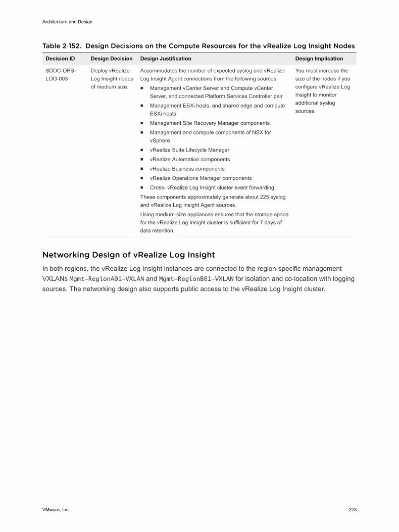
Table 2‑152. Design Decisions on the Compute Resources for the vRealize Log Insight Nodes
Decision ID Design Decision Design Justification Design Implication
SDDC-OPS-LOG-003
Deploy vRealizeLog Insight nodesof medium size.
Accommodates the number of expected syslog and vRealizeLog Insight Agent connections from the following sources:n Management vCenter Server and Compute vCenter
Server, and connected Platform Services Controller pairn Management ESXi hosts, and shared edge and compute
ESXi hostsn Management Site Recovery Manager componentsn Management and compute components of NSX for
vSpheren vRealize Suite Lifecycle Managern vRealize Automation componentsn vRealize Business componentsn vRealize Operations Manager componentsn Cross- vRealize Log Insight cluster event forwarding.
These components approximately generate about 225 syslogand vRealize Log Insight Agent sources.
Using medium-size appliances ensures that the storage spacefor the vRealize Log Insight cluster is sufficient for 7 days ofdata retention.
You must increase thesize of the nodes if youconfigure vRealize LogInsight to monitoradditional syslogsources.
Networking Design of vRealize Log Insight In both regions, the vRealize Log Insight instances are connected to the region-specific managementVXLANs Mgmt-RegionA01-VXLAN and Mgmt-RegionB01-VXLAN for isolation and co-location with loggingsources. The networking design also supports public access to the vRealize Log Insight cluster.
Architecture and Design
VMware, Inc. 223
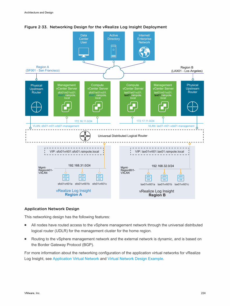
Figure 2‑33. Networking Design for the vRealize Log Insight Deployment
APP
OSAPP
OSAPP
OS
APP
OSAPP
OSAPP
OS
192.168.32.0/24
vRealize Log Insight Region B
192.168.31.0/24Mgmt-RegionA01-VXLAN
vRealize Log Insight Region A
Universal Distributed Logical Router
Mgmt-RegionB01-VXLAN
DataCenterUser
ActiveDirectory
Internet/EnterpriseNetwork
Region A(SF001 - San Francisco)
Management vCenter Serverlax01m01vc01.lax01.rainpole.
local
Compute vCenter Serverlax01w01vc01.lax01.rainpole.
local
VLAN: sfo01-m01-vds01-management
172.16.11.0/24
VLAN: lax01-m01-vds01-management
172.17.11.0/24
Management vCenter Server
sfo01m01vc01.sfo01.rainpole.
local
Compute vCenter Serversfo01w01vc01.sfo01.rainpole.
local
PhysicalUpstream
Router
Region B(LAX01 - Los Angeles)
PhysicalUpstream
Router
VIP: lax01vrli01.lax01.rainpole.local
lax01vrli01a lax01vrli01b lax01vrli01csfo01vrli01a sfo01vrli01b sfo01vrli01c
VIP: sfo01vrli01.sfo01.rainpole.local
Application Network Design
This networking design has the following features:
n All nodes have routed access to the vSphere management network through the universal distributedlogical router (UDLR) for the management cluster for the home region.
n Routing to the vSphere management network and the external network is dynamic, and is based onthe Border Gateway Protocol (BGP).
For more information about the networking configuration of the application virtual networks for vRealizeLog Insight, see Application Virtual Network and Virtual Network Design Example.
Architecture and Design
VMware, Inc. 224
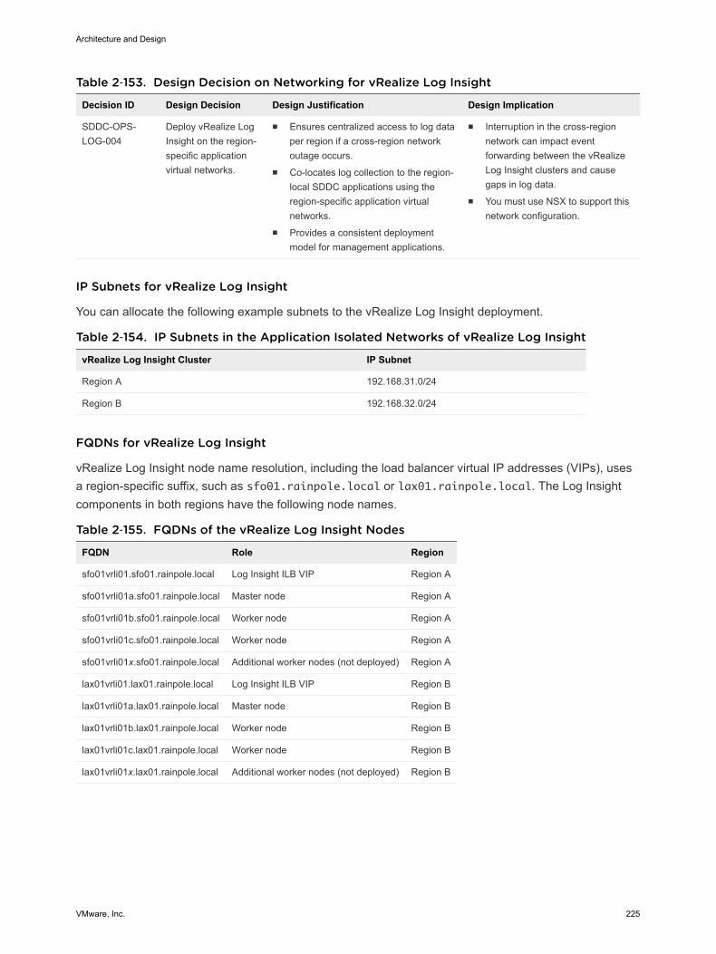
Table 2‑153. Design Decision on Networking for vRealize Log Insight
Decision ID Design Decision Design Justification Design Implication
SDDC-OPS-LOG-004
Deploy vRealize LogInsight on the region-specific applicationvirtual networks.
n Ensures centralized access to log dataper region if a cross-region networkoutage occurs.
n Co-locates log collection to the region-local SDDC applications using theregion-specific application virtualnetworks.
n Provides a consistent deploymentmodel for management applications.
n Interruption in the cross-regionnetwork can impact eventforwarding between the vRealizeLog Insight clusters and causegaps in log data.
n You must use NSX to support thisnetwork configuration.
IP Subnets for vRealize Log Insight
You can allocate the following example subnets to the vRealize Log Insight deployment.
Table 2‑154. IP Subnets in the Application Isolated Networks of vRealize Log Insight
vRealize Log Insight Cluster IP Subnet
Region A 192.168.31.0/24
Region B 192.168.32.0/24
FQDNs for vRealize Log Insight
vRealize Log Insight node name resolution, including the load balancer virtual IP addresses (VIPs), usesa region-specific suffix, such as sfo01.rainpole.local or lax01.rainpole.local. The Log Insightcomponents in both regions have the following node names.
Table 2‑155. FQDNs of the vRealize Log Insight Nodes
FQDN Role Region
sfo01vrli01.sfo01.rainpole.local Log Insight ILB VIP Region A
sfo01vrli01a.sfo01.rainpole.local Master node Region A
sfo01vrli01b.sfo01.rainpole.local Worker node Region A
sfo01vrli01c.sfo01.rainpole.local Worker node Region A
sfo01vrli01x.sfo01.rainpole.local Additional worker nodes (not deployed) Region A
lax01vrli01.lax01.rainpole.local Log Insight ILB VIP Region B
lax01vrli01a.lax01.rainpole.local Master node Region B
lax01vrli01b.lax01.rainpole.local Worker node Region B
lax01vrli01c.lax01.rainpole.local Worker node Region B
lax01vrli01x.lax01.rainpole.local Additional worker nodes (not deployed) Region B
Architecture and Design
VMware, Inc. 225
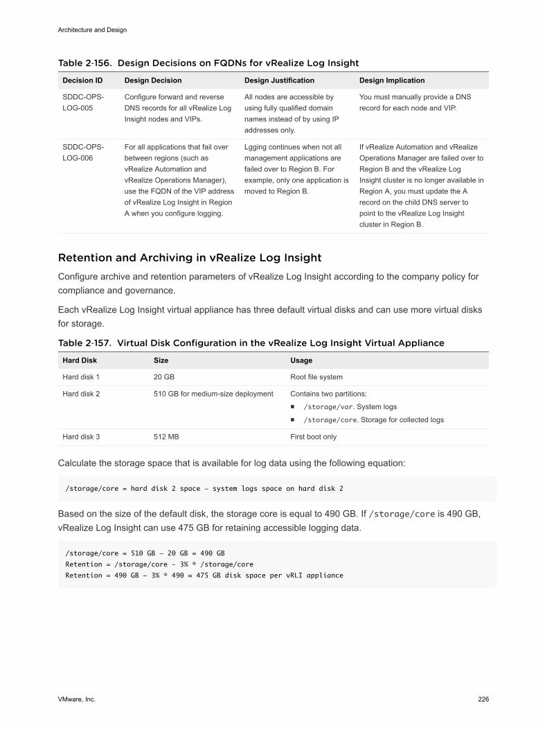
Table 2‑156. Design Decisions on FQDNs for vRealize Log Insight
Decision ID Design Decision Design Justification Design Implication
SDDC-OPS-LOG-005
Configure forward and reverseDNS records for all vRealize LogInsight nodes and VIPs.
All nodes are accessible byusing fully qualified domainnames instead of by using IPaddresses only.
You must manually provide a DNSrecord for each node and VIP.
SDDC-OPS-LOG-006
For all applications that fail overbetween regions (such asvRealize Automation andvRealize Operations Manager),use the FQDN of the VIP addressof vRealize Log Insight in RegionA when you configure logging.
Lgging continues when not allmanagement applications arefailed over to Region B. Forexample, only one application ismoved to Region B.
If vRealize Automation and vRealizeOperations Manager are failed over toRegion B and the vRealize LogInsight cluster is no longer available inRegion A, you must update the Arecord on the child DNS server topoint to the vRealize Log Insightcluster in Region B.
Retention and Archiving in vRealize Log Insight Configure archive and retention parameters of vRealize Log Insight according to the company policy forcompliance and governance.
Each vRealize Log Insight virtual appliance has three default virtual disks and can use more virtual disksfor storage.
Table 2‑157. Virtual Disk Configuration in the vRealize Log Insight Virtual Appliance
Hard Disk Size Usage
Hard disk 1 20 GB Root file system
Hard disk 2 510 GB for medium-size deployment Contains two partitions:n /storage/var. System logsn /storage/core. Storage for collected logs
Hard disk 3 512 MB First boot only
Calculate the storage space that is available for log data using the following equation:
/storage/core = hard disk 2 space - system logs space on hard disk 2
Based on the size of the default disk, the storage core is equal to 490 GB. If /storage/core is 490 GB,vRealize Log Insight can use 475 GB for retaining accessible logging data.
/storage/core = 510 GB - 20 GB = 490 GB
Retention = /storage/core – 3% * /storage/core
Retention = 490 GB - 3% * 490 ≈ 475 GB disk space per vRLI appliance
Architecture and Design
VMware, Inc. 226
You can calculate retention time by using the following equations:
GB per vRLI Appliance per day = (Amount in GB of disk space used per day / Number of vRLI appliances)
* 1.7 indexing
Retention in days = 475 GB disk space per vRLI appliance / GB per vRLI Appliance per day
(42 GB of logging data ingested per day / 3 vRLI appliances) * 1.7 indexing ≈ 24 GB per vRLI Appliance
per day
475 GB disk space per vRLI appliance / 24 GB per vRLI Appliance per Day ≈ 20 days of retention
Configure a retention period of 7 days for the medium-size vRealize Log Insight appliance.
Table 2‑158. Design Decision on Retention Period in vRealize Log Insight
Decision ID Design Decision Design Justification Design Implication
SDDC-OPS-LOG-007 Configure vRealize Log Insight toretain data for 7 days.
Accommodates logs from 220 syslogsources and vRealize Log Insight Agents asper the SDDC design.
None.
Archiving
You configure vRealize Log Insight to archive log data only if you must retain logs for an extended periodfor compliance, auditability, or a customer-specific reason.
Attribute of LogArchiving Description
Archiving period vRealize Log Insight archives log messages as soon as possible. At the same time, the logs areretained on the virtual appliance until the free local space is almost filled. Data exists on both thevRealize Log Insight appliance and the archive location for most of the retention period. Thearchiving period must be longer than the retention period.
Archive location The archive location must be on an NFS version 3 shared storage. The archive location must beavailable and must have enough capacity to accommodate the archives.
Apply an archive policy of 90 days for the medium-size vRealize Log Insight appliance. The vRealize LogInsight clusters will each use approximately 400 GB of shared storage calculated via the following:
(Average Storage Utilization (GB) per Day sources * Days of Retention) / Number of vRLI appliances ≈
Recommended Storage in GB
((((Recommended Storage Per Node * Number of vRLI appliances) / Days of Retention) * Days of
Archiving) * 10%) ≈ Archiving to NFS in GB
(42 GB * 7 Days) / 3 vRLI appliances = 98 GB ≈ 100 GB of Recommended Storage (rounded up)
((((100 GB * 3 vRLI appliances) / 7 Days of Retention) * 90 Days of Archiving) * 10%) = 386 GB ≈ 400
GB of NFS
According to the business compliance regulations of your organization, these sizes might change.
Architecture and Design
VMware, Inc. 227
Table 2‑159. Design Decision on Log Archive Policy for vRealize Log Insight
Decision ID Design Decision Design Justification Design Implication
SDDC-OPS-LOG-008
Provide 400 GB of NFS version 3shared storage to each vRealizeLog Insight cluster.
Accommodates log archivingfrom 225 logging sources for90 days.
n You must manually maintain thevRealize Log Insight archive blobsstored on the NFS store,selectively cleaning the datastoreas more space is required.
n You must increase the size of theNFS shared storage if youconfigure vRealize Log Insight tomonitor more logging sources oradd more vRealize Log Insightworkers are added.
n You must enforce the archivepolicy directly on the sharedstorage.
n If the NFS mount does not haveenough free space or isunavailable for a period greaterthan the retention period of thevirtual appliance, vRealize LogInsight stops ingesting new datauntil the NFS mount has enoughfree space, becomes available, orarchiving is disabled.
n When using two availability zones,ensure that the NFS share isavailable in both availability zones.
Alerting in vRealize Log Insight vRealize Log Insight supports alerts that trigger notifications about its health and about the health ofmonitored solutions.
Alert Types
The following types of alerts exist in vRealize Log Insight:
System Alerts vRealize Log Insight generates notifications when an important systemevent occurs, for example, when the disk space is almost exhausted andvRealize Log Insight must start deleting or archiving old log files.
Content Pack Alerts Content packs contain default alerts that can be configured to sendnotifications. These alerts are specific to the content pack and are disabledby default.
User-Defined Alerts Administrators and users can define their own alerts based on dataingested by vRealize Log Insight.
Architecture and Design
VMware, Inc. 228
vRealize Log Insight handles alerts in two ways:
n Send an e-mail over SMTP.
n Send to vRealize Operations Manager.
SMTP Notification
Enable e-mail notification for alerts in vRealize Log Insight.
Table 2‑160. Design Decision on SMTP Alert Notification for vRealize Log Insight
Decision ID Design Decision Design Justification Design Implication
SDDC-OPS-LOG-009 Enable alerting overSMTP.
Enables administrators and operators toreceive alerts by email from vRealizeLog Insight.
Requires access to an externalSMTP server.
Integration of vRealize Log Insight with vRealize Operations Manager vRealize Log Insight supports integration with vRealize Operations Manager to provide a central locationfor monitoring and diagnostics.
You can use the following integration points that you can enable separately:
Notification Events Forward notification events from vRealize Log Insight to vRealizeOperations Manager.
Launch in Context Launch vRealize Log Insight from the vRealize Operation Manager userinterface.
Embedded vRealizeLog Insight
Access the integrated vRealize Log Insight user interface directly in thevRealize Operations Manager user interface.
Table 2‑161. Design Decisions on Integration of vRealize Log Insight with vRealizeOperations Manager
Decision ID Design Decision Design Justification Design Implication
SDDC-OPS-LOG-010
Forward alerts to vRealizeOperations Manager.
Provides monitoring and alertinginformation that is pushed from vRealizeLog Insight to vRealize OperationsManager for centralized administration.
None.
SDDC-OPS-LOG-011
Support launch in contextwith vRealize OperationManager.
Provides access to vRealize Log Insightfor context-based monitoring of an objectin vRealize Operations Manager.
You can register only onevRealize Log Insight clusterwith vRealize OperationsManager for launch in contextat a time.
SDDC-OPS-LOG-012
Enable embeddedvRealize Log Insight userinterface in vRealizeOperations Manager.
Provides central access to vRealize LogInsight user interface for improvedcontext-based monitoring on an object invRealize Operations Manager.
You can register only onevRealize Log Insight clusterwith vRealize OperationsManager at a time.
Architecture and Design
VMware, Inc. 229
Information Security and Access Control in vRealize Log Insight Protect the vRealize Log Insight deployment by providing centralized role-based authentication andsecure communication with the other components in the SDDC.
Authentication
Enable role-based access control in vRealize Log Insight by using the existing rainpole.local ActiveDirectory domain.
Table 2‑162. Design Decisions on Authorization and Authentication Management in vRealizeLog Insight
Decision ID Design Decision Design Justification Design Implication
SDDC-OPS-LOG-013 Use Active Directory forauthentication.
Provides fine-grained role andprivilege-based access foradministrator and operator roles.
You must provide access tothe Active Directory from allLog Insight nodes.
SDDC-OPS-LOG-014 Configure a service accountsvc-vrli-vsphere on vCenterServer for application-to-application communicationfrom vRealize Log Insightwith vSphere.
Provides the following access controlfeatures:n vRealize Log Insight accesses
vSphere with the minimum set ofpermissions that are required tocollect vCenter Server events,tasks, and alarms and to configureESXi hosts for syslog forwarding.
n If there is a compromised account,the accessibility in the destinationapplication remains restricted.
n You can introduce improvedaccountability in tracking request-response interactions between thecomponents of the SDDC.
You must maintain the serviceaccount's life cycle outside ofthe SDDC stack to ensure itsavailability.
Architecture and Design
VMware, Inc. 230
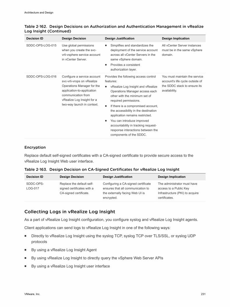
Table 2‑162. Design Decisions on Authorization and Authentication Management in vRealizeLog Insight (Continued)
Decision ID Design Decision Design Justification Design Implication
SDDC-OPS-LOG-015 Use global permissionswhen you create the svc-vrli-vsphere service accountin vCenter Server.
n Simplifies and standardizes thedeployment of the service accountacross all vCenter Servers in thesame vSphere domain.
n Provides a consistentauthorization layer.
All vCenter Server instancesmust be in the same vSpheredomain.
SDDC-OPS-LOG-016 Configure a service accountsvc-vrli-vrops on vRealizeOperations Manager for theapplication-to-applicationcommunication fromvRealize Log Insight for atwo-way launch in context.
Provides the following access controlfeatures:n vRealize Log Insight and vRealize
Operations Manager access eachother with the minimum set ofrequired permissions.
n If there is a compromised account,the accessibility in the destinationapplication remains restricted.
n You can introduce improvedaccountability in tracking request-response interactions between thecomponents of the SDDC.
You must maintain the serviceaccount's life cycle outside ofthe SDDC stack to ensure itsavailability.
Encryption
Replace default self-signed certificates with a CA-signed certificate to provide secure access to thevRealize Log Insight Web user interface.
Table 2‑163. Design Decision on CA-Signed Certificates for vRealize Log Insight
Decision ID Design Decision Design Justification Design Implication
SDDC-OPS-LOG-017
Replace the default self-signed certificates with aCA-signed certificate.
Configuring a CA-signed certificateensures that all communication tothe externally facing Web UI isencrypted.
The administrator must haveaccess to a Public KeyInfrastructure (PKI) to acquirecertificates.
Collecting Logs in vRealize Log Insight As a part of vRealize Log Insight configuration, you configure syslog and vRealize Log Insight agents.
Client applications can send logs to vRealize Log Insight in one of the following ways:
n Directly to vRealize Log Insight using the syslog TCP, syslog TCP over TLS/SSL, or syslog UDPprotocols
n By using a vRealize Log Insight Agent
n By using vRealize Log Insight to directly query the vSphere Web Server APIs
n By using a vRealize Log Insight user interface
Architecture and Design
VMware, Inc. 231

Table 2‑164. Design Decisions on Log Communication to vRealize Log Insight
Decision ID Design Decision Design Justification Design Implication
SDDC-OPS-LOG-018
Configure syslog sources andvRealize Log Insight Agents tosend log data directly to thevirtual IP (VIP) address of thevRealize Log Insight integratedload balancer (ILB).
n Allows for future scale-outwithout reconfiguring all logsources with a newdestination address.
n Simplifies the configuration oflog sources in the SDDC
n You must configure theintegrated load balanceron the vRealize LogInsight cluster.
n You must configurelogging sources to forwarddata to the vRealize LogInsight VIP.
SDDC-OPS-LOG-019
Communicate with the vRealizeLog Insight Agents using thedefault Ingestion API (cfapi),default disk buffer of 200 MB andnon-default No SSL.
n Supports multi-line messagetransmissions from logs.
n Provides ability to addmetadata to events generatedfrom system.
n Provides client-sidecompression, buffering, andthrottling capabilities ensuringminimal to no message lossduring intermittent connectionissues
n Provides server-sideadministration, metriccollection, configurationsmanagement of eachdeployed agent.
n Supports disaster recovery ofcomponents in the SDDC.
n Transmission traffic is notsecure.
n Agent presence increasesthe overall resources usedon the system.
SDDC-OPS-LOG-020
Configure the vRealize LogInsight agent on the vRealizeSuite Lifecycle Managerappliance.
Simplifies configuration of logsources in the SDDC that are pre-packaged with the vRealize LogInsight agent.
You must configure thevRealize Log Insight agent toforward logs to the vRealizeLog Insight VIP.
SDDC-OPS-LOG-021
Deploy and configure thevRealize Log Insight agent for thevRealize Automation Windowsservers.
n Windows does not nativelysupport syslog.
n vRealize Automation requiresthe use of agents to collect allvRealize Automation logs.
You must manually install andconfigure the agents onseveral nodes.
SDDC-OPS-LOG-022
Configure the vRealize LogInsight agent on the vRealizeAutomation appliance.
Simplifies configuration of logsources in the SDDC that are pre-packaged with the vRealize LogInsight agent.
You must configure thevRealize Log Insight agent toforward logs to the vRealizeLog Insight VIP.
SDDC-OPS-LOG-023
Configure the vRealize LogInsight agent for the vRealizeBusiness appliances including:n Server appliancen Data collectors
Simplifies configuration of logsources in the SDDC that are pre-packaged with the vRealize LogInsight agent.
You must configure thevRealize Log Insight agent toforward logs to the vRealizeLog Insight VIP.
Architecture and Design
VMware, Inc. 232
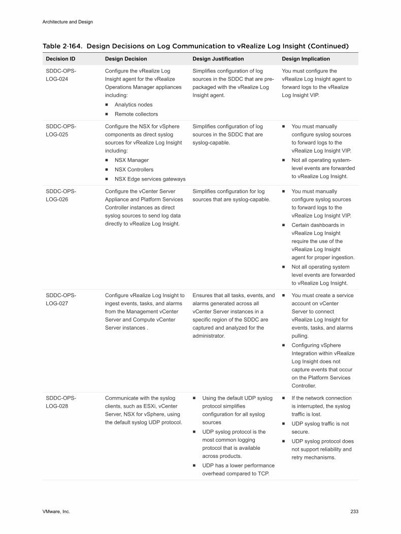
Table 2‑164. Design Decisions on Log Communication to vRealize Log Insight (Continued)
Decision ID Design Decision Design Justification Design Implication
SDDC-OPS-LOG-024
Configure the vRealize LogInsight agent for the vRealizeOperations Manager appliancesincluding:n Analytics nodesn Remote collectors
Simplifies configuration of logsources in the SDDC that are pre-packaged with the vRealize LogInsight agent.
You must configure thevRealize Log Insight agent toforward logs to the vRealizeLog Insight VIP.
SDDC-OPS-LOG-025
Configure the NSX for vSpherecomponents as direct syslogsources for vRealize Log Insightincluding:n NSX Managern NSX Controllersn NSX Edge services gateways
Simplifies configuration of logsources in the SDDC that aresyslog-capable.
n You must manuallyconfigure syslog sourcesto forward logs to thevRealize Log Insight VIP.
n Not all operating system-level events are forwardedto vRealize Log Insight.
SDDC-OPS-LOG-026
Configure the vCenter ServerAppliance and Platform ServicesController instances as directsyslog sources to send log datadirectly to vRealize Log Insight.
Simplifies configuration for logsources that are syslog-capable.
n You must manuallyconfigure syslog sourcesto forward logs to thevRealize Log Insight VIP.
n Certain dashboards invRealize Log Insightrequire the use of thevRealize Log Insightagent for proper ingestion.
n Not all operating systemlevel events are forwardedto vRealize Log Insight.
SDDC-OPS-LOG-027
Configure vRealize Log Insight toingest events, tasks, and alarmsfrom the Management vCenterServer and Compute vCenterServer instances .
Ensures that all tasks, events, andalarms generated across allvCenter Server instances in aspecific region of the SDDC arecaptured and analyzed for theadministrator.
n You must create a serviceaccount on vCenterServer to connectvRealize Log Insight forevents, tasks, and alarmspulling.
n Configuring vSphereIntegration within vRealizeLog Insight does notcapture events that occuron the Platform ServicesController.
SDDC-OPS-LOG-028
Communicate with the syslogclients, such as ESXi, vCenterServer, NSX for vSphere, usingthe default syslog UDP protocol.
n Using the default UDP syslogprotocol simplifiesconfiguration for all syslogsources
n UDP syslog protocol is themost common loggingprotocol that is availableacross products.
n UDP has a lower performanceoverhead compared to TCP.
n If the network connectionis interrupted, the syslogtraffic is lost.
n UDP syslog traffic is notsecure.
n UDP syslog protocol doesnot support reliability andretry mechanisms.
Architecture and Design
VMware, Inc. 233
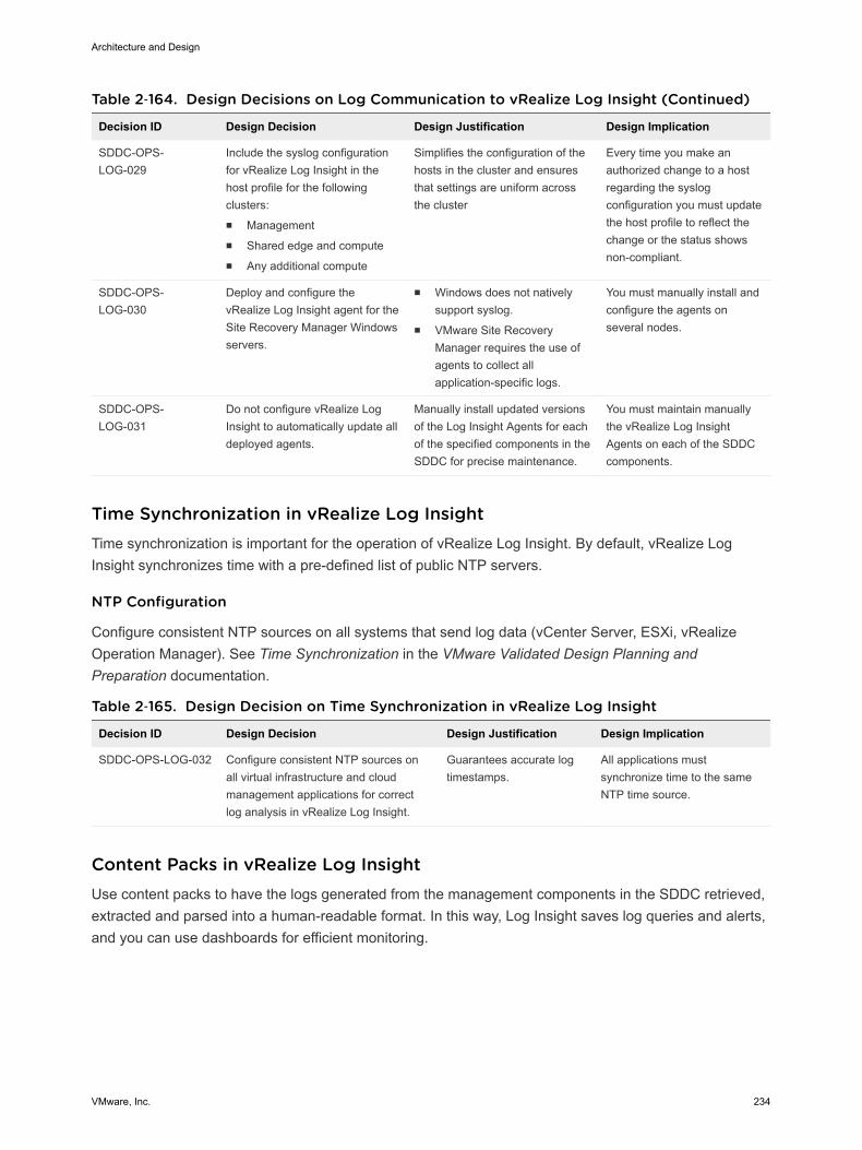
Table 2‑164. Design Decisions on Log Communication to vRealize Log Insight (Continued)
Decision ID Design Decision Design Justification Design Implication
SDDC-OPS-LOG-029
Include the syslog configurationfor vRealize Log Insight in thehost profile for the followingclusters:n Managementn Shared edge and computen Any additional compute
Simplifies the configuration of thehosts in the cluster and ensuresthat settings are uniform acrossthe cluster
Every time you make anauthorized change to a hostregarding the syslogconfiguration you must updatethe host profile to reflect thechange or the status showsnon-compliant.
SDDC-OPS-LOG-030
Deploy and configure thevRealize Log Insight agent for theSite Recovery Manager Windowsservers.
n Windows does not nativelysupport syslog.
n VMware Site RecoveryManager requires the use ofagents to collect allapplication-specific logs.
You must manually install andconfigure the agents onseveral nodes.
SDDC-OPS-LOG-031
Do not configure vRealize LogInsight to automatically update alldeployed agents.
Manually install updated versionsof the Log Insight Agents for eachof the specified components in theSDDC for precise maintenance.
You must maintain manuallythe vRealize Log InsightAgents on each of the SDDCcomponents.
Time Synchronization in vRealize Log Insight Time synchronization is important for the operation of vRealize Log Insight. By default, vRealize LogInsight synchronizes time with a pre-defined list of public NTP servers.
NTP Configuration
Configure consistent NTP sources on all systems that send log data (vCenter Server, ESXi, vRealizeOperation Manager). See Time Synchronization in the VMware Validated Design Planning andPreparation documentation.
Table 2‑165. Design Decision on Time Synchronization in vRealize Log Insight
Decision ID Design Decision Design Justification Design Implication
SDDC-OPS-LOG-032 Configure consistent NTP sources onall virtual infrastructure and cloudmanagement applications for correctlog analysis in vRealize Log Insight.
Guarantees accurate logtimestamps.
All applications mustsynchronize time to the sameNTP time source.
Content Packs in vRealize Log Insight Use content packs to have the logs generated from the management components in the SDDC retrieved,extracted and parsed into a human-readable format. In this way, Log Insight saves log queries and alerts,and you can use dashboards for efficient monitoring.
Architecture and Design
VMware, Inc. 234
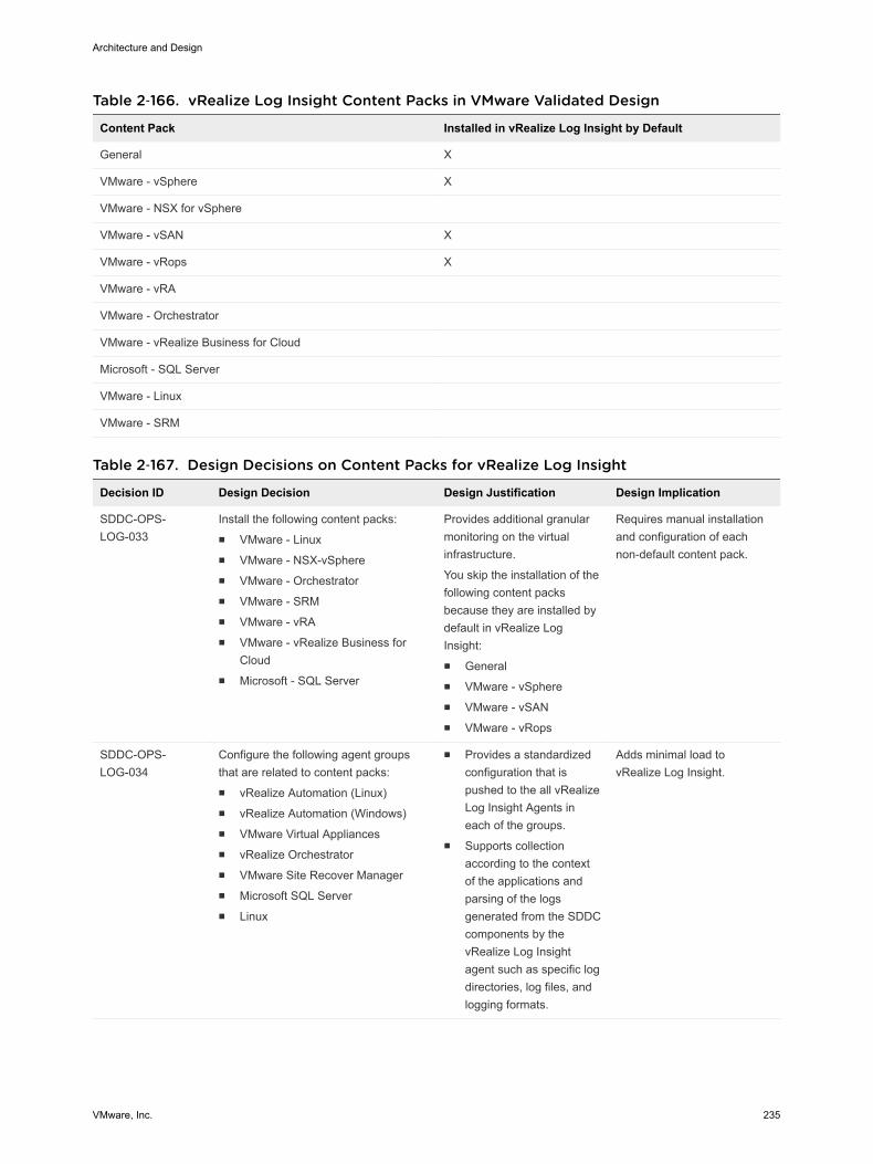
Table 2‑166. vRealize Log Insight Content Packs in VMware Validated Design
Content Pack Installed in vRealize Log Insight by Default
General X
VMware - vSphere X
VMware - NSX for vSphere
VMware - vSAN X
VMware - vRops X
VMware - vRA
VMware - Orchestrator
VMware - vRealize Business for Cloud
Microsoft - SQL Server
VMware - Linux
VMware - SRM
Table 2‑167. Design Decisions on Content Packs for vRealize Log Insight
Decision ID Design Decision Design Justification Design Implication
SDDC-OPS-LOG-033
Install the following content packs:n VMware - Linuxn VMware - NSX-vSpheren VMware - Orchestratorn VMware - SRMn VMware - vRAn VMware - vRealize Business for
Cloudn Microsoft - SQL Server
Provides additional granularmonitoring on the virtualinfrastructure.
You skip the installation of thefollowing content packsbecause they are installed bydefault in vRealize LogInsight:n Generaln VMware - vSpheren VMware - vSANn VMware - vRops
Requires manual installationand configuration of eachnon-default content pack.
SDDC-OPS-LOG-034
Configure the following agent groupsthat are related to content packs:n vRealize Automation (Linux)n vRealize Automation (Windows)n VMware Virtual Appliancesn vRealize Orchestratorn VMware Site Recover Managern Microsoft SQL Servern Linux
n Provides a standardizedconfiguration that ispushed to the all vRealizeLog Insight Agents ineach of the groups.
n Supports collectionaccording to the contextof the applications andparsing of the logsgenerated from the SDDCcomponents by thevRealize Log Insightagent such as specific logdirectories, log files, andlogging formats.
Adds minimal load tovRealize Log Insight.
Architecture and Design
VMware, Inc. 235
Event Forwarding Between Regions with vRealize Log Insight vRealize Log Insight supports event forwarding to other clusters and standalone instances. Use logforwarding between SDDC regions to have access to all logs if a disaster occurs in a region.
You forward syslog data in vRealize Log Insight by using the Ingestion API or a native syslogimplementation. While forwarding events, the vRealize Log Insight instance still ingests, stores, andarchives events locally.
The vRealize Log Insight Ingestion API uses TCP communication. In contrast to syslog, the forwardingmodule supports the following features for the Ingestion API:
n Forwarding to other vRealize Log Insight instances
n Support for both structured and unstructured data, that is, multi-line messages
n Metadata in the form of tags
n Client-side compression
n Configurable disk-backed queue to save events until the server acknowledges the ingestion
Architecture and Design
VMware, Inc. 236
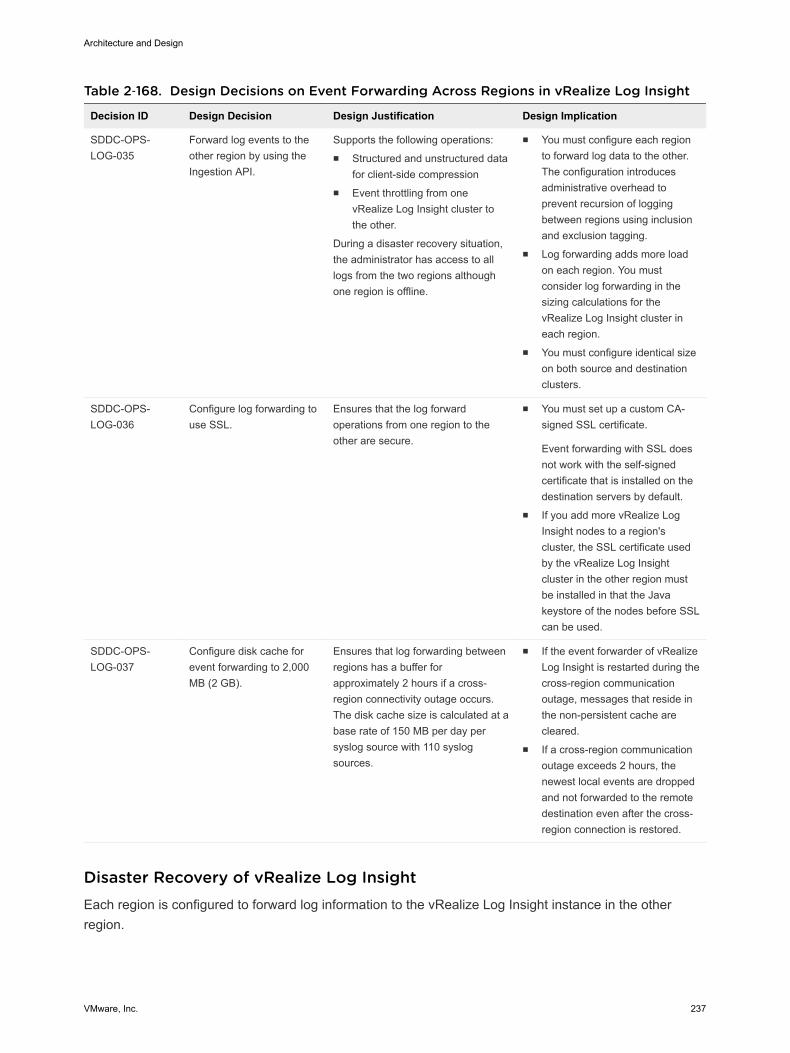
Table 2‑168. Design Decisions on Event Forwarding Across Regions in vRealize Log Insight
Decision ID Design Decision Design Justification Design Implication
SDDC-OPS-LOG-035
Forward log events to theother region by using theIngestion API.
Supports the following operations:n Structured and unstructured data
for client-side compressionn Event throttling from one
vRealize Log Insight cluster tothe other.
During a disaster recovery situation,the administrator has access to alllogs from the two regions althoughone region is offline.
n You must configure each regionto forward log data to the other.The configuration introducesadministrative overhead toprevent recursion of loggingbetween regions using inclusionand exclusion tagging.
n Log forwarding adds more loadon each region. You mustconsider log forwarding in thesizing calculations for thevRealize Log Insight cluster ineach region.
n You must configure identical sizeon both source and destinationclusters.
SDDC-OPS-LOG-036
Configure log forwarding touse SSL.
Ensures that the log forwardoperations from one region to theother are secure.
n You must set up a custom CA-signed SSL certificate.
Event forwarding with SSL doesnot work with the self-signedcertificate that is installed on thedestination servers by default.
n If you add more vRealize LogInsight nodes to a region'scluster, the SSL certificate usedby the vRealize Log Insightcluster in the other region mustbe installed in that the Javakeystore of the nodes before SSLcan be used.
SDDC-OPS-LOG-037
Configure disk cache forevent forwarding to 2,000MB (2 GB).
Ensures that log forwarding betweenregions has a buffer forapproximately 2 hours if a cross-region connectivity outage occurs.The disk cache size is calculated at abase rate of 150 MB per day persyslog source with 110 syslogsources.
n If the event forwarder of vRealizeLog Insight is restarted during thecross-region communicationoutage, messages that reside inthe non-persistent cache arecleared.
n If a cross-region communicationoutage exceeds 2 hours, thenewest local events are droppedand not forwarded to the remotedestination even after the cross-region connection is restored.
Disaster Recovery of vRealize Log InsightEach region is configured to forward log information to the vRealize Log Insight instance in the otherregion.
Architecture and Design
VMware, Inc. 237
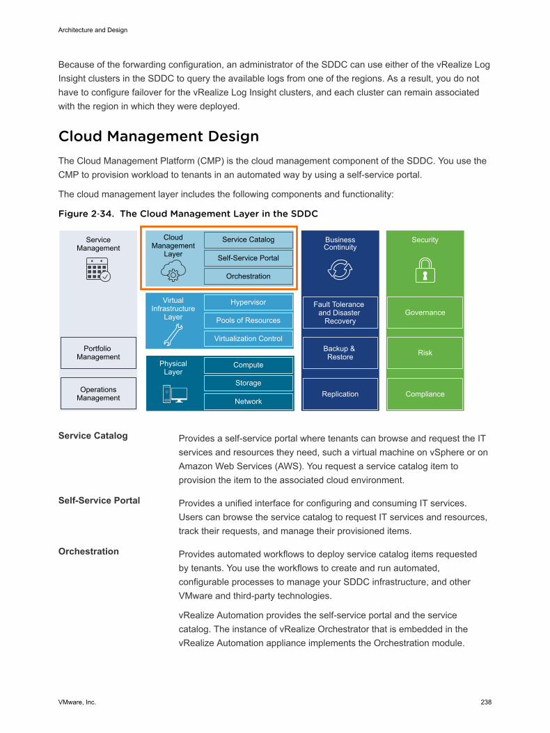
Because of the forwarding configuration, an administrator of the SDDC can use either of the vRealize LogInsight clusters in the SDDC to query the available logs from one of the regions. As a result, you do nothave to configure failover for the vRealize Log Insight clusters, and each cluster can remain associatedwith the region in which they were deployed.
Cloud Management Design The Cloud Management Platform (CMP) is the cloud management component of the SDDC. You use theCMP to provision workload to tenants in an automated way by using a self-service portal.
The cloud management layer includes the following components and functionality:
Figure 2‑34. The Cloud Management Layer in the SDDC
ServiceManagement
Portfolio Management
OperationsManagement
CloudManagement
Layer
Service Catalog
Self-Service Portal
Orchestration
BusinessContinuity
Fault Tolerance and Disaster
Recovery
Backup & Restore
Hypervisor
Pools of Resources
Virtualization Control
VirtualInfrastructure
Layer
Compute
Storage
Network
PhysicalLayer
Security
Replication Compliance
Risk
Governance
Service Catalog Provides a self-service portal where tenants can browse and request the ITservices and resources they need, such a virtual machine on vSphere or onAmazon Web Services (AWS). You request a service catalog item toprovision the item to the associated cloud environment.
Self-Service Portal Provides a unified interface for configuring and consuming IT services.Users can browse the service catalog to request IT services and resources,track their requests, and manage their provisioned items.
Orchestration Provides automated workflows to deploy service catalog items requestedby tenants. You use the workflows to create and run automated,configurable processes to manage your SDDC infrastructure, and otherVMware and third-party technologies.
vRealize Automation provides the self-service portal and the servicecatalog. The instance of vRealize Orchestrator that is embedded in thevRealize Automation appliance implements the Orchestration module.
Architecture and Design
VMware, Inc. 238
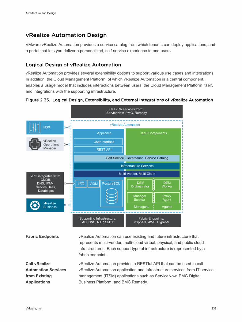
vRealize Automation Design VMware vRealize Automation provides a service catalog from which tenants can deploy applications, anda portal that lets you deliver a personalized, self-service experience to end users.
Logical Design of vRealize Automation vRealize Automation provides several extensibility options to support various use cases and integrations.In addition, the Cloud Management Platform, of which vRealize Automation is a central component,enables a usage model that includes interactions between users, the Cloud Management Platform itself,and integrations with the supporting infrastructure.
Figure 2‑35. Logical Design, Extensibility, and External Integrations of vRealize Automation
PostgreSQL vRO VIDM
Call vRA services from: ServiceNow, PMG, Remedy
Supporting Infrastructure: AD, DNS, NTP, SMTP
Fabric Endpoints: vSphere, AWS, Hyper-V
ProxyAgent
vRealize Automation
Appliance
User Interface
IaaS Components
DEMOrchestrator
DEMWorker
ManagerService
Managers Agents
REST API
vRealizeBusiness
vRealizeOperationsManager
Self-Service, Governance, Service Catalog
Infrastructure Services
Multi-Vendor, Multi-CloudvRO integrates with:
CMDB,DNS, IPAM,
Service Desk, Databases
NSX
Fabric Endpoints vRealize Automation can use existing and future infrastructure thatrepresents multi-vendor, multi-cloud virtual, physical, and public cloudinfrastructures. Each support type of infrastructure is represented by afabric endpoint.
Call vRealizeAutomation Servicesfrom ExistingApplications
vRealize Automation provides a RESTful API that can be used to callvRealize Automation application and infrastructure services from IT servicemanagement (ITSM) applications such as ServiceNow, PMG DigitalBusiness Platform, and BMC Remedy.
Architecture and Design
VMware, Inc. 239
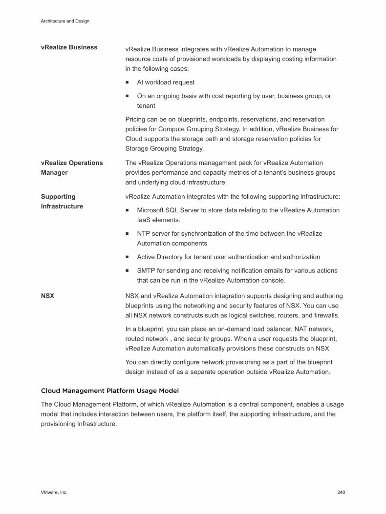
vRealize Business vRealize Business integrates with vRealize Automation to manageresource costs of provisioned workloads by displaying costing informationin the following cases:
n At workload request
n On an ongoing basis with cost reporting by user, business group, ortenant
Pricing can be on blueprints, endpoints, reservations, and reservationpolicies for Compute Grouping Strategy. In addition, vRealize Business forCloud supports the storage path and storage reservation policies forStorage Grouping Strategy.
vRealize OperationsManager
The vRealize Operations management pack for vRealize Automationprovides performance and capacity metrics of a tenant’s business groupsand underlying cloud infrastructure.
SupportingInfrastructure
vRealize Automation integrates with the following supporting infrastructure:
n Microsoft SQL Server to store data relating to the vRealize AutomationIaaS elements.
n NTP server for synchronization of the time between the vRealizeAutomation components
n Active Directory for tenant user authentication and authorization
n SMTP for sending and receiving notification emails for various actionsthat can be run in the vRealize Automation console.
NSX NSX and vRealize Automation integration supports designing and authoringblueprints using the networking and security features of NSX. You can useall NSX network constructs such as logical switches, routers, and firewalls.
In a blueprint, you can place an on-demand load balancer, NAT network,routed network , and security groups. When a user requests the blueprint,vRealize Automation automatically provisions these constructs on NSX.
You can directly configure network provisioning as a part of the blueprintdesign instead of as a separate operation outside vRealize Automation.
Cloud Management Platform Usage Model
The Cloud Management Platform, of which vRealize Automation is a central component, enables a usagemodel that includes interaction between users, the platform itself, the supporting infrastructure, and theprovisioning infrastructure.
Architecture and Design
VMware, Inc. 240
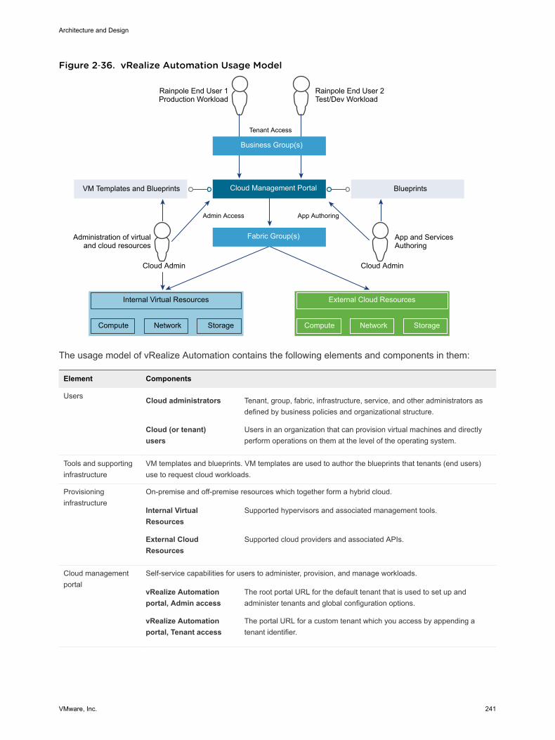
Figure 2‑36. vRealize Automation Usage Model
Compute
Business Group(s)
Rainpole End User 1Production Workload
Rainpole End User 2Test/Dev Workload
Fabric Group(s)
Cloud Management PortalVM Templates and Blueprints
Tenant Access
Administration of virtualand cloud resources
Internal Virtual Resources
Network Storage Compute
External Cloud Resources
Network Storage
Cloud Admin
Admin Access
Blueprints
App and ServicesAuthoring
Cloud Admin
App Authoring
The usage model of vRealize Automation contains the following elements and components in them:
Element Components
Users Cloud administrators Tenant, group, fabric, infrastructure, service, and other administrators asdefined by business policies and organizational structure.
Cloud (or tenant)users
Users in an organization that can provision virtual machines and directlyperform operations on them at the level of the operating system.
Tools and supportinginfrastructure
VM templates and blueprints. VM templates are used to author the blueprints that tenants (end users)use to request cloud workloads.
Provisioninginfrastructure
On-premise and off-premise resources which together form a hybrid cloud.
Internal VirtualResources
Supported hypervisors and associated management tools.
External CloudResources
Supported cloud providers and associated APIs.
Cloud managementportal
Self-service capabilities for users to administer, provision, and manage workloads.
vRealize Automationportal, Admin access
The root portal URL for the default tenant that is used to set up andadminister tenants and global configuration options.
vRealize Automationportal, Tenant access
The portal URL for a custom tenant which you access by appending atenant identifier.
Architecture and Design
VMware, Inc. 241

Physical Design of vRealize Automation The physical design consists of characteristics and decisions that support the logical design. The designobjective is to deploy a fully functional cloud management portal with high availability and the ability toprovision to both Regions A and B.
To accomplish this design objective, you deploy or leverage the following in Region A to create a cloudmanagement portal of the SDDC.
n 3 vRealize Automation Server Appliances
n 2 vRealize Automation IaaS Web Servers.
n 2 vRealize Automation Manager Service nodes (including the DEM Orchestrator)
n 2 DEM Worker nodes
n 2 IaaS Proxy Agent nodes
n 1 vRealize Business for Cloud Server
n 1 vRealize Business for Cloud Remote Collector
n Supporting infrastructure such as Microsoft SQL Server, Active Directory, DNS, NTP, and SMTP.
You place the vRealize Automation components in several network units for isolation and failover.
Architecture and Design
VMware, Inc. 242
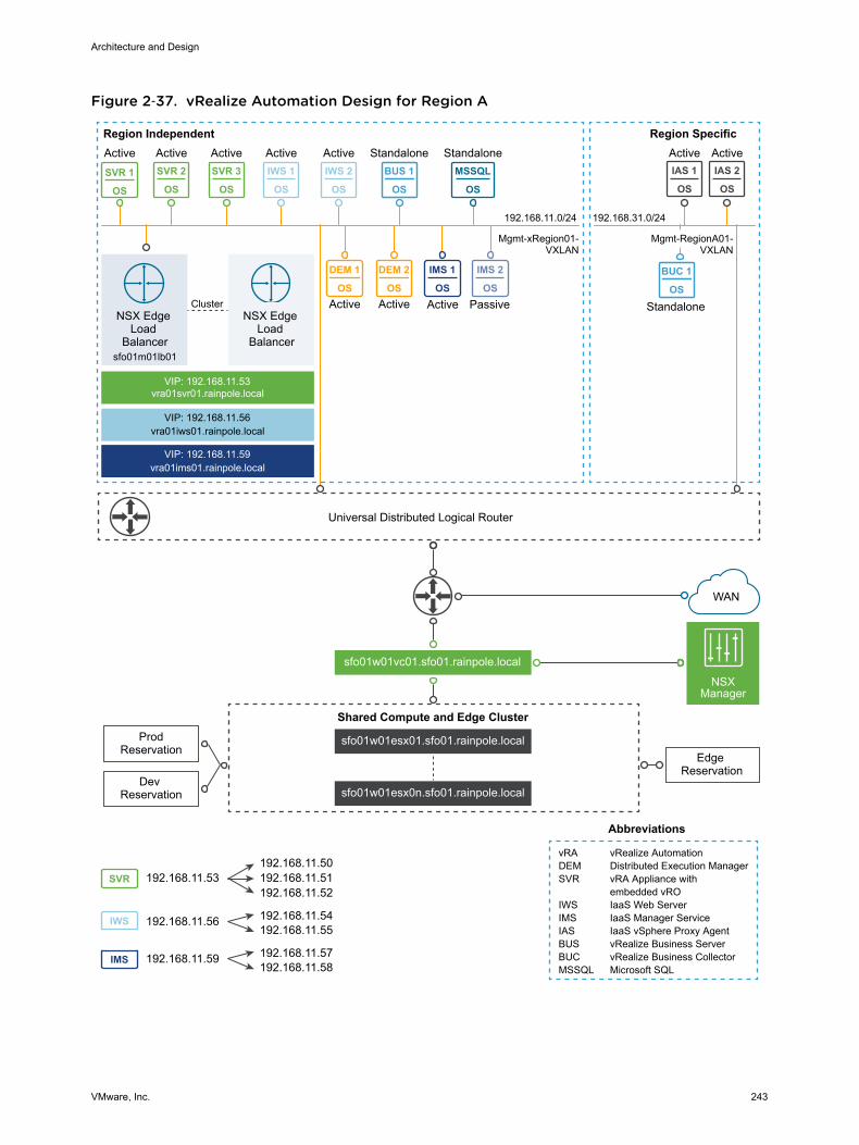
Figure 2‑37. vRealize Automation Design for Region A
IWS 1
OS
MSSQL
OS
IMS 1
OS
DEM 1
OS
DEM 2
OS
SVR 2
OS
SVR 3
OS
IWS 2
OS
IAS 1
OS
IAS 2
OS
IWS
IMS
SVR
BUC 1
OS
BUS 1
OSSVR 1
OS
IMS 2
OS
Universal Distributed Logical Router
VIP: 192.168.11.53vra01svr01.rainpole.local
VIP: 192.168.11.56vra01iws01.rainpole.local
VIP: 192.168.11.59vra01ims01.rainpole.local
Active Active Standalone Standalone
Active PassiveActive Active
Active Active Active Active Active
Mgmt-xRegion01-VXLAN
Region Independent Region Specific
NSX Edge Load
Balancersfo01m01lb01
NSX Edge Load
Balancer
Cluster
Edge Reservation
WAN
Abbreviations
vRA vRealize AutomationDEM Distributed Execution ManagerSVR vRA Appliance with embedded vROIWS IaaS Web ServerIMS IaaS Manager ServiceIAS IaaS vSphere Proxy AgentBUS vRealize Business ServerBUC vRealize Business CollectorMSSQL Microsoft SQL
sfo01w01vc01.sfo01.rainpole.local
sfo01w01esx01.sfo01.rainpole.local
sfo01w01esx0n.sfo01.rainpole.local
Shared Compute and Edge Cluster
NSXManager
Dev Reservation
ProdReservation
192.168.11.56 192.168.11.54192.168.11.55
192.168.11.59 192.168.11.57192.168.11.58
192.168.11.53 192.168.11.51192.168.11.50
192.168.11.52
Mgmt-RegionA01-VXLAN
Standalone
192.168.11.0/24 192.168.31.0/24
Architecture and Design
VMware, Inc. 243
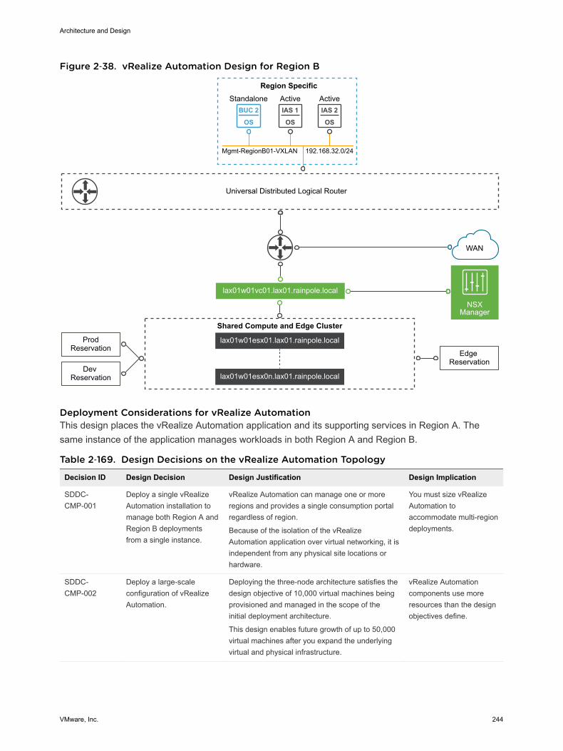
Figure 2‑38. vRealize Automation Design for Region B
IAS 1
OS
IAS 2
OS
BUC 2
OS
Region Specific
Universal Distributed Logical Router
Active Active
Edge Reservation
WAN
lax01w01vc01.lax01.rainpole.local
lax01w01esx01.lax01.rainpole.local
lax01w01esx0n.lax01.rainpole.local
Shared Compute and Edge Cluster
NSXManager
Dev Reservation
ProdReservation
Mgmt-RegionB01-VXLAN
Standalone
192.168.32.0/24
Deployment Considerations for vRealize Automation This design places the vRealize Automation application and its supporting services in Region A. Thesame instance of the application manages workloads in both Region A and Region B.
Table 2‑169. Design Decisions on the vRealize Automation Topology
Decision ID Design Decision Design Justification Design Implication
SDDC-CMP-001
Deploy a single vRealizeAutomation installation tomanage both Region A andRegion B deploymentsfrom a single instance.
vRealize Automation can manage one or moreregions and provides a single consumption portalregardless of region.
Because of the isolation of the vRealizeAutomation application over virtual networking, it isindependent from any physical site locations orhardware.
You must size vRealizeAutomation toaccommodate multi-regiondeployments.
SDDC-CMP-002
Deploy a large-scaleconfiguration of vRealizeAutomation.
Deploying the three-node architecture satisfies thedesign objective of 10,000 virtual machines beingprovisioned and managed in the scope of theinitial deployment architecture.
This design enables future growth of up to 50,000virtual machines after you expand the underlyingvirtual and physical infrastructure.
vRealize Automationcomponents use moreresources than the designobjectives define.
Architecture and Design
VMware, Inc. 244
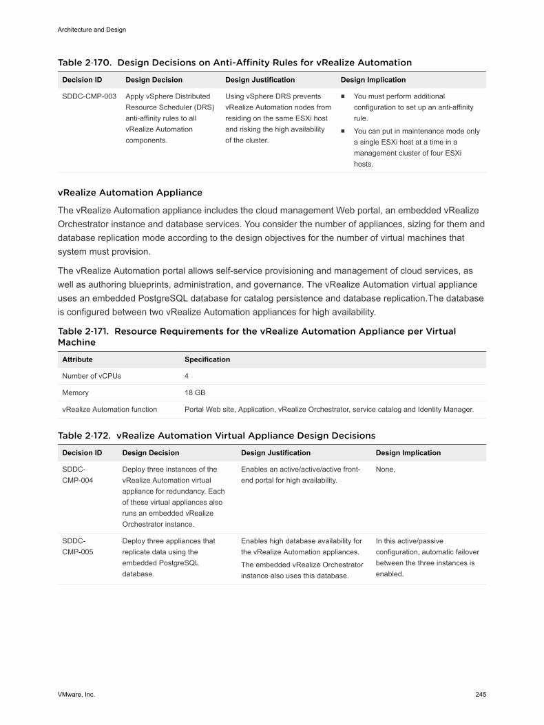
Table 2‑170. Design Decisions on Anti-Affinity Rules for vRealize Automation
Decision ID Design Decision Design Justification Design Implication
SDDC-CMP-003 Apply vSphere DistributedResource Scheduler (DRS)anti-affinity rules to allvRealize Automationcomponents.
Using vSphere DRS preventsvRealize Automation nodes fromresiding on the same ESXi hostand risking the high availabilityof the cluster.
n You must perform additionalconfiguration to set up an anti-affinityrule.
n You can put in maintenance mode onlya single ESXi host at a time in amanagement cluster of four ESXihosts.
vRealize Automation Appliance
The vRealize Automation appliance includes the cloud management Web portal, an embedded vRealizeOrchestrator instance and database services. You consider the number of appliances, sizing for them anddatabase replication mode according to the design objectives for the number of virtual machines thatsystem must provision.
The vRealize Automation portal allows self-service provisioning and management of cloud services, aswell as authoring blueprints, administration, and governance. The vRealize Automation virtual applianceuses an embedded PostgreSQL database for catalog persistence and database replication.The databaseis configured between two vRealize Automation appliances for high availability.
Table 2‑171. Resource Requirements for the vRealize Automation Appliance per VirtualMachine
Attribute Specification
Number of vCPUs 4
Memory 18 GB
vRealize Automation function Portal Web site, Application, vRealize Orchestrator, service catalog and Identity Manager.
Table 2‑172. vRealize Automation Virtual Appliance Design Decisions
Decision ID Design Decision Design Justification Design Implication
SDDC-CMP-004
Deploy three instances of thevRealize Automation virtualappliance for redundancy. Eachof these virtual appliances alsoruns an embedded vRealizeOrchestrator instance.
Enables an active/active/active front-end portal for high availability.
None.
SDDC-CMP-005
Deploy three appliances thatreplicate data using theembedded PostgreSQLdatabase.
Enables high database availability forthe vRealize Automation appliances.
The embedded vRealize Orchestratorinstance also uses this database.
In this active/passiveconfiguration, automatic failoverbetween the three instances isenabled.
Architecture and Design
VMware, Inc. 245
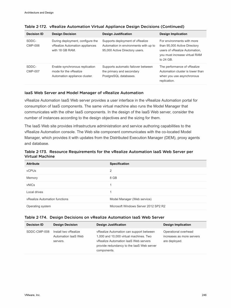
Table 2‑172. vRealize Automation Virtual Appliance Design Decisions (Continued)
Decision ID Design Decision Design Justification Design Implication
SDDC-CMP-006
During deployment, configure thevRealize Automation applianceswith 18 GB RAM.
Supports deployment of vRealizeAutomation in environments with up to95,000 Active Directory users.
For environments with morethan 95,000 Active Directoryusers of vRealize Automation,you must increase virtual RAMto 24 GB.
SDDC-CMP-007
Enable synchronous replicationmode for the vRealizeAutomation appliance cluster.
Supports automatic failover betweenthe primary and secondaryPostgreSQL databases.
The performance of vRealizeAutomation cluster is lower thanwhen you use asynchronousreplication.
IaaS Web Server and Model Manager of vRealize Automation
vRealize Automation IaaS Web server provides a user interface in the vRealize Automation portal forconsumption of IaaS components. The same virtual machine also runs the Model Manager thatcommunicates with the other IaaS components. In the design of the IaaS Web server, consider thenumber of instances according to the design objectives and the sizing for them.
The IaaS Web site provides infrastructure administration and service authoring capabilities to thevRealize Automation console. The Web site component communicates with the co-located ModelManager, which provides it with updates from the Distributed Execution Manager (DEM), proxy agentsand database.
Table 2‑173. Resource Requirements for the vRealize Automation IaaS Web Server perVirtual Machine
Attribute Specification
vCPUs 2
Memory 8 GB
vNICs 1
Local drives 1
vRealize Automation functions Model Manager (Web service)
Operating system Microsoft Windows Server 2012 SP2 R2
Table 2‑174. Design Decisions on vRealize Automation IaaS Web Server
Decision ID Design Decision Design Justification Design Implication
SDDC-CMP-008 Install two vRealizeAutomation IaaS Webservers.
vRealize Automation can support between1,000 and 10,000 virtual machines. TwovRealize Automation IaaS Web serversprovide redundancy to the IaaS Web servercomponents.
Operational overheadincreases as more serversare deployed.
Architecture and Design
VMware, Inc. 246
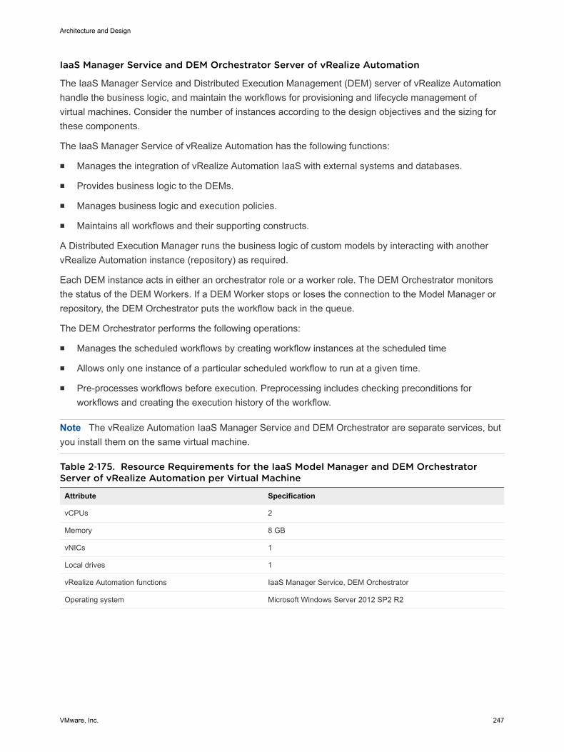
IaaS Manager Service and DEM Orchestrator Server of vRealize Automation
The IaaS Manager Service and Distributed Execution Management (DEM) server of vRealize Automationhandle the business logic, and maintain the workflows for provisioning and lifecycle management ofvirtual machines. Consider the number of instances according to the design objectives and the sizing forthese components.
The IaaS Manager Service оf vRealize Automation has the following functions:
n Manages the integration of vRealize Automation IaaS with external systems and databases.
n Provides business logic to the DEMs.
n Manages business logic and execution policies.
n Maintains all workflows and their supporting constructs.
A Distributed Execution Manager runs the business logic of custom models by interacting with anothervRealize Automation instance (repository) as required.
Each DEM instance acts in either an orchestrator role or a worker role. The DEM Orchestrator monitorsthe status of the DEM Workers. If a DEM Worker stops or loses the connection to the Model Manager orrepository, the DEM Orchestrator puts the workflow back in the queue.
The DEM Orchestrator performs the following operations:
n Manages the scheduled workflows by creating workflow instances at the scheduled time
n Allows only one instance of a particular scheduled workflow to run at a given time.
n Pre-processes workflows before execution. Preprocessing includes checking preconditions forworkflows and creating the execution history of the workflow.
Note The vRealize Automation IaaS Manager Service and DEM Orchestrator are separate services, butyou install them on the same virtual machine.
Table 2‑175. Resource Requirements for the IaaS Model Manager and DEM OrchestratorServer of vRealize Automation per Virtual Machine
Attribute Specification
vCPUs 2
Memory 8 GB
vNICs 1
Local drives 1
vRealize Automation functions IaaS Manager Service, DEM Orchestrator
Operating system Microsoft Windows Server 2012 SP2 R2
Architecture and Design
VMware, Inc. 247
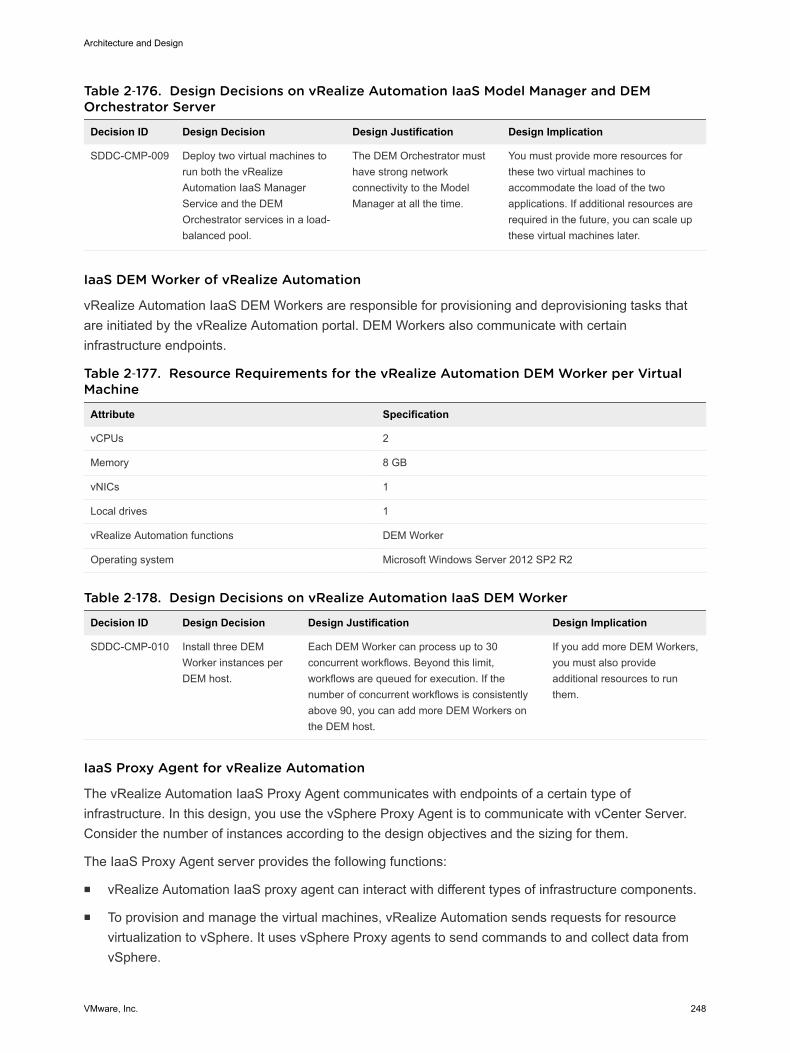
Table 2‑176. Design Decisions on vRealize Automation IaaS Model Manager and DEMOrchestrator Server
Decision ID Design Decision Design Justification Design Implication
SDDC-CMP-009 Deploy two virtual machines torun both the vRealizeAutomation IaaS ManagerService and the DEMOrchestrator services in a load-balanced pool.
The DEM Orchestrator musthave strong networkconnectivity to the ModelManager at all the time.
You must provide more resources forthese two virtual machines toaccommodate the load of the twoapplications. If additional resources arerequired in the future, you can scale upthese virtual machines later.
IaaS DEM Worker of vRealize Automation
vRealize Automation IaaS DEM Workers are responsible for provisioning and deprovisioning tasks thatare initiated by the vRealize Automation portal. DEM Workers also communicate with certaininfrastructure endpoints.
Table 2‑177. Resource Requirements for the vRealize Automation DEM Worker per VirtualMachine
Attribute Specification
vCPUs 2
Memory 8 GB
vNICs 1
Local drives 1
vRealize Automation functions DEM Worker
Operating system Microsoft Windows Server 2012 SP2 R2
Table 2‑178. Design Decisions on vRealize Automation IaaS DEM Worker
Decision ID Design Decision Design Justification Design Implication
SDDC-CMP-010 Install three DEMWorker instances perDEM host.
Each DEM Worker can process up to 30concurrent workflows. Beyond this limit,workflows are queued for execution. If thenumber of concurrent workflows is consistentlyabove 90, you can add more DEM Workers onthe DEM host.
If you add more DEM Workers,you must also provideadditional resources to runthem.
IaaS Proxy Agent for vRealize Automation
The vRealize Automation IaaS Proxy Agent communicates with endpoints of a certain type ofinfrastructure. In this design, you use the vSphere Proxy Agent is to communicate with vCenter Server.Consider the number of instances according to the design objectives and the sizing for them.
The IaaS Proxy Agent server provides the following functions:
n vRealize Automation IaaS proxy agent can interact with different types of infrastructure components.
n To provision and manage the virtual machines, vRealize Automation sends requests for resourcevirtualization to vSphere. It uses vSphere Proxy agents to send commands to and collect data fromvSphere.
Architecture and Design
VMware, Inc. 248

Table 2‑179. Resource Requirements for the vRealize Automation IaaS Proxy Agent perVirtual Machine
Attribute Specification
vCPUs 2
Memory 8 GB
vNICs 1
Local drives 1
vRealize Automation functions vSphere Proxy Agent
Operating system Microsoft Windows Server 2012 SP2 R2
Table 2‑180. Design Decisions on the vRealize Automation IaaS Proxy Agent
Decision ID Design Decision Design Justification Design Implication
SDDC-CMP-011 Deploy two vRealize AutomationIaaS Proxy Agent virtualmachines.
Provides redundancy forvSphere connectivity.
You must provide more resourcesbecause you deploy multiple virtualmachines for this function.
Networking Design of vRealize Automation
As part of this design, use the application virtual network configuration to connect the vRealizeAutomation with the other management solutions in the SDDC. Use the load balancer in the cross-regionapplication virtual network for high availability and request balancing of the vRealize Automationcomponents.
This design uses NSX logical switches to abstract the vRealize Automation application and its supportingservices. You can place the application in any region regardless of the underlying physical infrastructuresuch as network subnets, compute hardware, or storage types.
Application Virtual Networks
The vRealize Automation appliance and main IaaS components are installed in the cross-region sharedapplication virtual network and the vSphere proxy agent nodes are installed in their region-specific sharedapplication virtual networks.
This networking design has the following features:
n The vRealize Automation appliance and IaaS nodes are on the same network because they can befailed over between regions after scaling out to a multi-region design. vRealize Automation andvRealize Business also share this network.
n All nodes have routed access to the vSphere management network through the NSX UniversalDistributed Logical Router.
n Routing to the vSphere management network and other external networks is dynamic and is basedon the Border Gateway Protocol (BGP).
For more information about the networking configuration of the application virtual network, see Virtualization Network Design and NSX Design.
Architecture and Design
VMware, Inc. 249
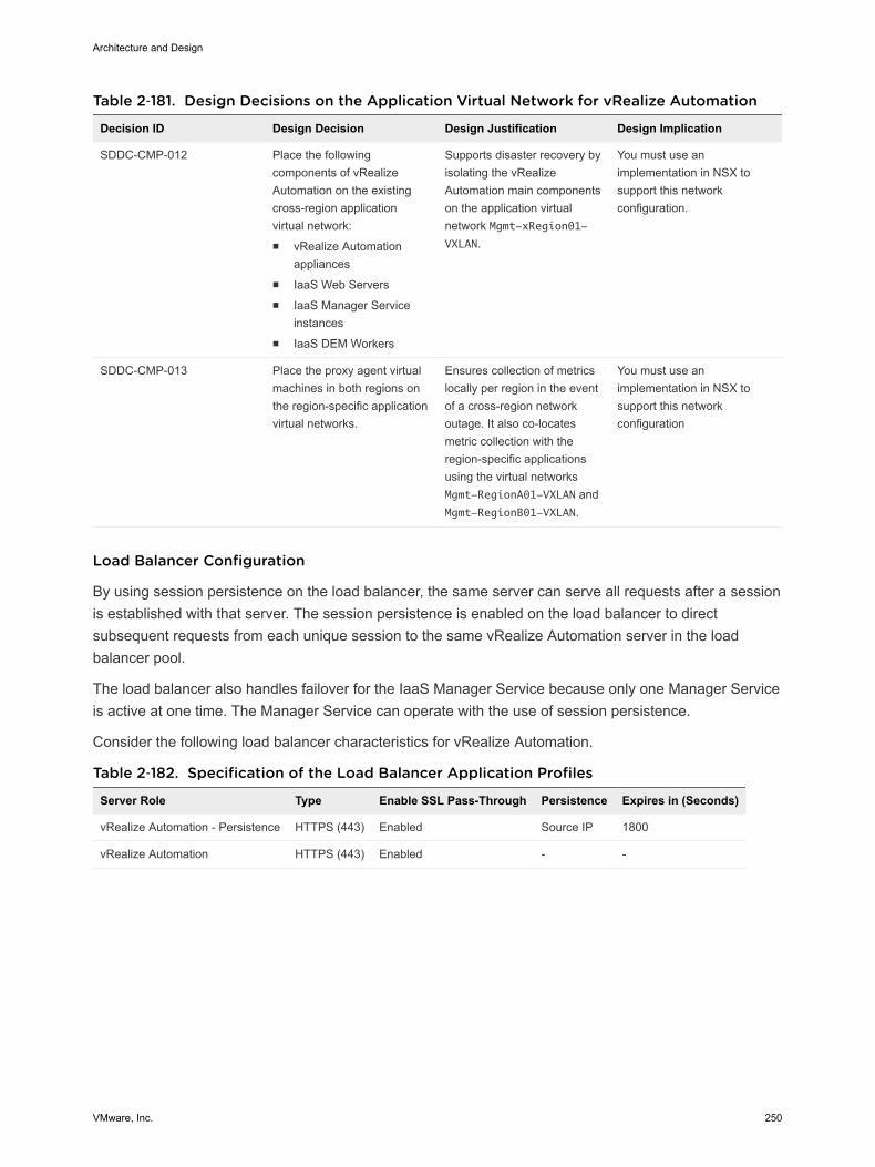
Table 2‑181. Design Decisions on the Application Virtual Network for vRealize Automation
Decision ID Design Decision Design Justification Design Implication
SDDC-CMP-012 Place the followingcomponents of vRealizeAutomation on the existingcross-region applicationvirtual network:n vRealize Automation
appliancesn IaaS Web Serversn IaaS Manager Service
instancesn IaaS DEM Workers
Supports disaster recovery byisolating the vRealizeAutomation main componentson the application virtualnetwork Mgmt-xRegion01-VXLAN.
You must use animplementation in NSX tosupport this networkconfiguration.
SDDC-CMP-013 Place the proxy agent virtualmachines in both regions onthe region-specific applicationvirtual networks.
Ensures collection of metricslocally per region in the eventof a cross-region networkoutage. It also co-locatesmetric collection with theregion-specific applicationsusing the virtual networksMgmt-RegionA01-VXLAN andMgmt-RegionB01-VXLAN.
You must use animplementation in NSX tosupport this networkconfiguration
Load Balancer Configuration
By using session persistence on the load balancer, the same server can serve all requests after a sessionis established with that server. The session persistence is enabled on the load balancer to directsubsequent requests from each unique session to the same vRealize Automation server in the loadbalancer pool.
The load balancer also handles failover for the IaaS Manager Service because only one Manager Serviceis active at one time. The Manager Service can operate with the use of session persistence.
Consider the following load balancer characteristics for vRealize Automation.
Table 2‑182. Specification of the Load Balancer Application Profiles
Server Role Type Enable SSL Pass-Through Persistence Expires in (Seconds)
vRealize Automation - Persistence HTTPS (443) Enabled Source IP 1800
vRealize Automation HTTPS (443) Enabled - -
Architecture and Design
VMware, Inc. 250
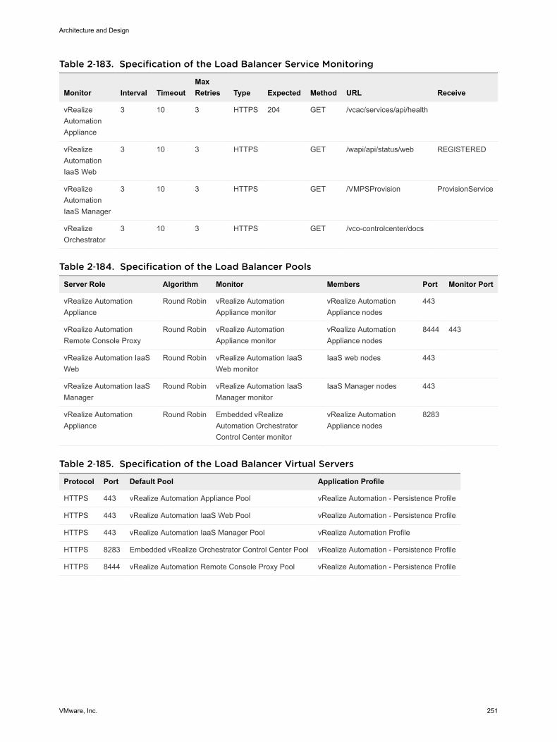
Table 2‑183. Specification of the Load Balancer Service Monitoring
Monitor Interval TimeoutMaxRetries Type Expected Method URL Receive
vRealizeAutomationAppliance
3 10 3 HTTPS 204 GET /vcac/services/api/health
vRealizeAutomationIaaS Web
3 10 3 HTTPS GET /wapi/api/status/web REGISTERED
vRealizeAutomationIaaS Manager
3 10 3 HTTPS GET /VMPSProvision ProvisionService
vRealizeOrchestrator
3 10 3 HTTPS GET /vco-controlcenter/docs
Table 2‑184. Specification of the Load Balancer Pools
Server Role Algorithm Monitor Members Port Monitor Port
vRealize AutomationAppliance
Round Robin vRealize AutomationAppliance monitor
vRealize AutomationAppliance nodes
443
vRealize AutomationRemote Console Proxy
Round Robin vRealize AutomationAppliance monitor
vRealize AutomationAppliance nodes
8444 443
vRealize Automation IaaSWeb
Round Robin vRealize Automation IaaSWeb monitor
IaaS web nodes 443
vRealize Automation IaaSManager
Round Robin vRealize Automation IaaSManager monitor
IaaS Manager nodes 443
vRealize AutomationAppliance
Round Robin Embedded vRealizeAutomation OrchestratorControl Center monitor
vRealize AutomationAppliance nodes
8283
Table 2‑185. Specification of the Load Balancer Virtual Servers
Protocol Port Default Pool Application Profile
HTTPS 443 vRealize Automation Appliance Pool vRealize Automation - Persistence Profile
HTTPS 443 vRealize Automation IaaS Web Pool vRealize Automation - Persistence Profile
HTTPS 443 vRealize Automation IaaS Manager Pool vRealize Automation Profile
HTTPS 8283 Embedded vRealize Orchestrator Control Center Pool vRealize Automation - Persistence Profile
HTTPS 8444 vRealize Automation Remote Console Proxy Pool vRealize Automation - Persistence Profile
Architecture and Design
VMware, Inc. 251

Table 2‑186. Design Decisions on Load Balancing vRealize Automation
Decision ID Design Decision Design Justification Design Implication
SDDC-CMP-014
Set up an NSX edge device for loadbalancing the vRealize Automationservices.
Required to enable vRealize Automation tohandle a greater load and obtain a higher levelof availability than without load balancers.
Additionalconfiguration isrequired to configurethe load balancer.
SDDC-CMP-015
Configure the load balancer for thevRealize Automation appliance,Remote Console Proxy, and IaaSWeb Server to use Round-Robinalgorithm with Source-IP basedpersistence with a 1800 secondtimeout.
n Round-robin provides a good balance ofclients between both appliances, while theSource-IP ensures that individual clientsremain connected to the same appliance.
n 1800-second timeout aligns with thevRealize Automation Appliance Serversessions timeout value. Sessions thattransfer to a different vRealize AutomationAppliance might result in a poor userexperience.
None
SDDC-CMP-016
Configure the load balancer forvRealize IaaS Manager Service touse Round-Robin algorithm withoutpersistence.
The Manager Service does not need sessionpersistence.
None
Information Security and Access Control in vRealize Automation
For orchestrating and creating virtual objects in the SDDC, you use a service account for authenticationand authorization of vRealize Automation to vCenter Server and vRealize Operations Manager.
Authentication and Authorization
Users can authenticate to vRealize Automation in the following ways:
Import users or usergroups from an LDAPdatabase
Users can use their LDAP credentials to log in to vRealize Automation.
Create local useraccounts in vRealizeOperations Manager
vRealize Automation performs local authentication using accountinformation stored in its global database.
vRealize Automation also authenticates to the following systems:
n Compute vCenter Server and NSX for workload provisioning
n vRealize Operations Manager for workload reclamation
Architecture and Design
VMware, Inc. 252
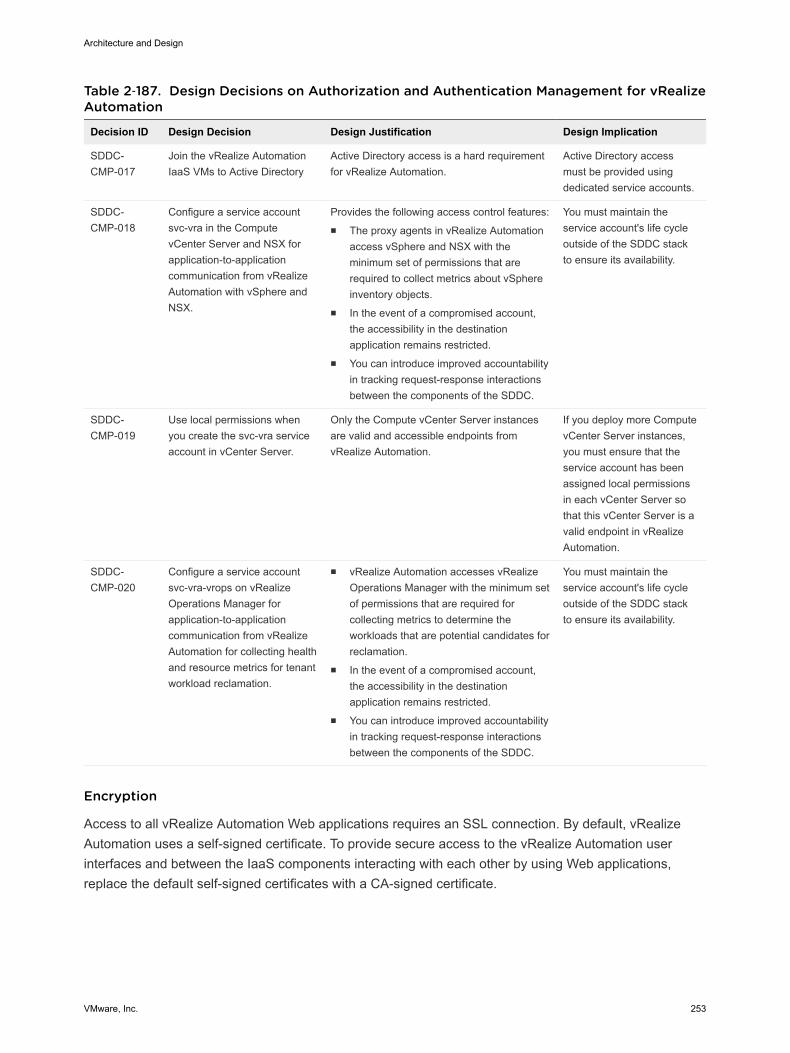
Table 2‑187. Design Decisions on Authorization and Authentication Management for vRealizeAutomation
Decision ID Design Decision Design Justification Design Implication
SDDC-CMP-017
Join the vRealize AutomationIaaS VMs to Active Directory
Active Directory access is a hard requirementfor vRealize Automation.
Active Directory accessmust be provided usingdedicated service accounts.
SDDC-CMP-018
Configure a service accountsvc-vra in the ComputevCenter Server and NSX forapplication-to-applicationcommunication from vRealizeAutomation with vSphere andNSX.
Provides the following access control features:n The proxy agents in vRealize Automation
access vSphere and NSX with theminimum set of permissions that arerequired to collect metrics about vSphereinventory objects.
n In the event of a compromised account,the accessibility in the destinationapplication remains restricted.
n You can introduce improved accountabilityin tracking request-response interactionsbetween the components of the SDDC.
You must maintain theservice account's life cycleoutside of the SDDC stackto ensure its availability.
SDDC-CMP-019
Use local permissions whenyou create the svc-vra serviceaccount in vCenter Server.
Only the Compute vCenter Server instancesare valid and accessible endpoints fromvRealize Automation.
If you deploy more ComputevCenter Server instances,you must ensure that theservice account has beenassigned local permissionsin each vCenter Server sothat this vCenter Server is avalid endpoint in vRealizeAutomation.
SDDC-CMP-020
Configure a service accountsvc-vra-vrops on vRealizeOperations Manager forapplication-to-applicationcommunication from vRealizeAutomation for collecting healthand resource metrics for tenantworkload reclamation.
n vRealize Automation accesses vRealizeOperations Manager with the minimum setof permissions that are required forcollecting metrics to determine theworkloads that are potential candidates forreclamation.
n In the event of a compromised account,the accessibility in the destinationapplication remains restricted.
n You can introduce improved accountabilityin tracking request-response interactionsbetween the components of the SDDC.
You must maintain theservice account's life cycleoutside of the SDDC stackto ensure its availability.
Encryption
Access to all vRealize Automation Web applications requires an SSL connection. By default, vRealizeAutomation uses a self-signed certificate. To provide secure access to the vRealize Automation userinterfaces and between the IaaS components interacting with each other by using Web applications,replace the default self-signed certificates with a CA-signed certificate.
Architecture and Design
VMware, Inc. 253
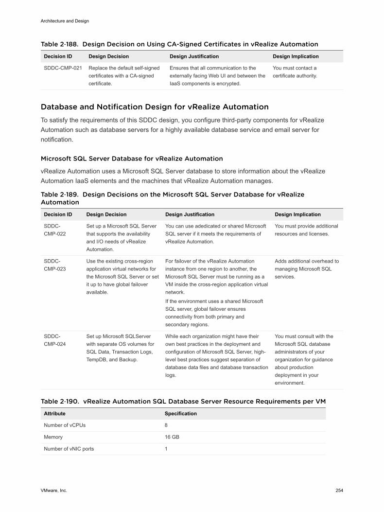
Table 2‑188. Design Decision on Using CA-Signed Certificates in vRealize Automation
Decision ID Design Decision Design Justification Design Implication
SDDC-CMP-021 Replace the default self-signedcertificates with a CA-signedcertificate.
Ensures that all communication to theexternally facing Web UI and between theIaaS components is encrypted.
You must contact acertificate authority.
Database and Notification Design for vRealize Automation To satisfy the requirements of this SDDC design, you configure third-party components for vRealizeAutomation such as database servers for a highly available database service and email server fornotification.
Microsoft SQL Server Database for vRealize Automation
vRealize Automation uses a Microsoft SQL Server database to store information about the vRealizeAutomation IaaS elements and the machines that vRealize Automation manages.
Table 2‑189. Design Decisions on the Microsoft SQL Server Database for vRealizeAutomation
Decision ID Design Decision Design Justification Design Implication
SDDC-CMP-022
Set up a Microsoft SQL Serverthat supports the availabilityand I/O needs of vRealizeAutomation.
You can use adedicated or shared MicrosoftSQL server if it meets the requirements ofvRealize Automation.
You must provide additionalresources and licenses.
SDDC-CMP-023
Use the existing cross-regionapplication virtual networks forthe Microsoft SQL Server or setit up to have global failoveravailable.
For failover of the vRealize Automationinstance from one region to another, theMicrosoft SQL Server must be running as aVM inside the cross-region application virtualnetwork.
If the environment uses a shared MicrosoftSQL server, global failover ensuresconnectivity from both primary andsecondary regions.
Adds additional overhead tomanaging Microsoft SQLservices.
SDDC-CMP-024
Set up Microsoft SQLServerwith separate OS volumes forSQL Data, Transaction Logs,TempDB, and Backup.
While each organization might have theirown best practices in the deployment andconfiguration of Microsoft SQL Server, high-level best practices suggest separation ofdatabase data files and database transactionlogs.
You must consult with theMicrosoft SQL databaseadministrators of yourorganization for guidanceabout productiondeployment in yourenvironment.
Table 2‑190. vRealize Automation SQL Database Server Resource Requirements per VM
Attribute Specification
Number of vCPUs 8
Memory 16 GB
Number of vNIC ports 1
Architecture and Design
VMware, Inc. 254

Table 2‑190. vRealize Automation SQL Database Server Resource Requirements per VM(Continued)
Attribute Specification
Number of local drives 1
40 GB (D:) (Application)
40 GB (E:) Database Data
20 GB (F:) Database Log
20 GB (G:) TempDB
80 GB (H:) Backup
vRealize Automation functions Microsoft SQL Server Database
Microsoft SQL Version SQL Server 2012
Microsoft SQL Database Version SQL Server 2012 Standard or higher edition (64-bit)
Operating system Microsoft Windows Server 2012 R2
PostgreSQL Database Server for vRealize Automation
The vRealize Automation Appliance uses a PostgreSQL database server to maintain the vRealizeAutomation portal elements and services, and the information about the catalog items that the appliancemanages. The PostgreSQL is also used to host data pertaining to the embedded instance of vRealizeOrchestrator.
Table 2‑191. Design Decisions on the PostgreSQL Database in vRealize Automation
Decision ID Design Decision Design Justification Design Implication
SDDC-CMP-025 Use the embedded PostgreSQL databaseserver in each vRealize AutomationAppliance. This database is also used by theembedded vRealize Orchestrator.
Simplifies the design and enablesreplication of the database across thethree vRealize Automation appliances.
None.
Notifications from vRealize Automation
System administrators configure default settings for both the outbound and inbound emails servers usedto send system notifications. Systems administrators can create only one of each type of server thatappears as the default for all tenants. If tenant administrators do not override these settings beforeenabling notifications, vRealize Automation uses the globally configured email server.
vRealize Automation sends notification emails over SMTP. These emails include notification of machinecreation, expiration, and the notification of approvals received by users. vRealize Automation supportsboth anonymous connections to the SMTP server and connections using basic authentication. vRealizeAutomation also supports communication with or without SSL.
You assign a global, inbound email server to handle inbound email notifications, such as approvalresponses.
Architecture and Design
VMware, Inc. 255
The email server provides accounts that you can customize for each user. Each tenant can override thesesettings. If tenant administrators do not override these settings before enabling notifications, vRealizeAutomation uses the globally configured email server. vRealize Automation supports both the POP andthe IMAP protocols, with or without SSL certificates.
Table 2‑192. Design Decisions on Email Server Configuration for vRealize Automation
Decision ID Design Decision Design Justification Design Implication
SDDC-CMP-026 Configure vRealize Automation to usea global outbound email server tohandle outbound email notificationsand a global inbound email server tohandle inbound email notifications,such as approval responses.
Requirement to integratevRealize Automationapprovals and systemnotifications through emails.
You must prepare the SMTP/IMAPserver and necessary firewall accessand create a mailbox for inboundemails (IMAP), and anonymousaccess can be used with outboundemails.
Cloud Tenant Design for vRealize Automation A tenant is an organizational unit within a vRealize Automation deployment, and can represent a businessunit within an enterprise, or a company that subscribes to cloud services from a service provider. Eachtenant has its own dedicated configuration, although some system-level configuration is shared acrosstenants.
Comparison Between Single-Tenant and Multi-Tenant Deployments of vRealize Automation
vRealize Automation supports deployments with a single tenant or multiple tenants. System-wideconfiguration is always performed using the default tenant, and can then be applied to one or moretenants. For example, system-wide configuration might specify defaults for branding and notificationproviders.
Infrastructure configuration, including the infrastructure sources that are available for provisioning, can beconfigured in any tenant and is shared among all tenants. You organize your infrastructure resources,such as cloud or virtual compute resources, in fabric groups and assign a fabric administrator to managethose resources. Fabric administrators can allocate resources in their fabric group to business groups bycreating reservations.
Default-TenantDeployment
In a default-tenant deployment, all configuration occurs in the defaulttenant. Tenant administrators can manage users and groups, and configuretenant-specific branding, notifications, business policies, and catalogofferings. All users log in to the vRealize Automation console at the sameURL, but the features available to them are determined by their roles.
Single-TenantDeployment
In a single-tenant deployment, the system administrator creates a singletenant for the organization that uses the same vRealize Automationinstance. Tenant users log in to the vRealize Automation console at a URLthat is specific to the tenant. Tenant-level configuration is isolated from thedefault tenant, although users with system-wide roles, such as system
Architecture and Design
VMware, Inc. 256
administrator and IaaS administrator, can view and manage bothconfigurations. The IaaS administrator for the organization tenant createsfabric groups and assigns fabric administrators. Fabric administrators cancreate reservations for business groups in the organization tenant.
Multi-TenantDeployment
In a multi-tenant deployment, the system administrator creates tenants foreach organization that uses the same vRealize Automation instance.Tenant users log in to the vRealize Automation console at a URL specific totheir tenant. Tenant-level configuration is isolated from other tenants andfrom the default tenant, although users with system-wide roles can viewand manage configuration across multiple tenants. The IaaS administratorfor each tenant creates fabric groups and assigns fabric administrators totheir respective tenants. Although fabric administrators can createreservations for business groups in any tenant, in this scenario theytypically create and manage reservations within their own tenants. If thesame identity store is configured in multiple tenants, the same users can beIaaS administrators or fabric administrators for each tenant.
Tenant Design for vRealize Automation
This design deploys a single tenant containing two business groups.
n The first business group is for production workloads provisioning.
n The second business group is for development workloads.
Tenant administrators manage users and groups, configure tenant-specific branding, notifications,business policies, and catalog offerings. All users log in to the vRealize Automation console using thesame URL, but the features available to them are determined per their role.
Architecture and Design
VMware, Inc. 257
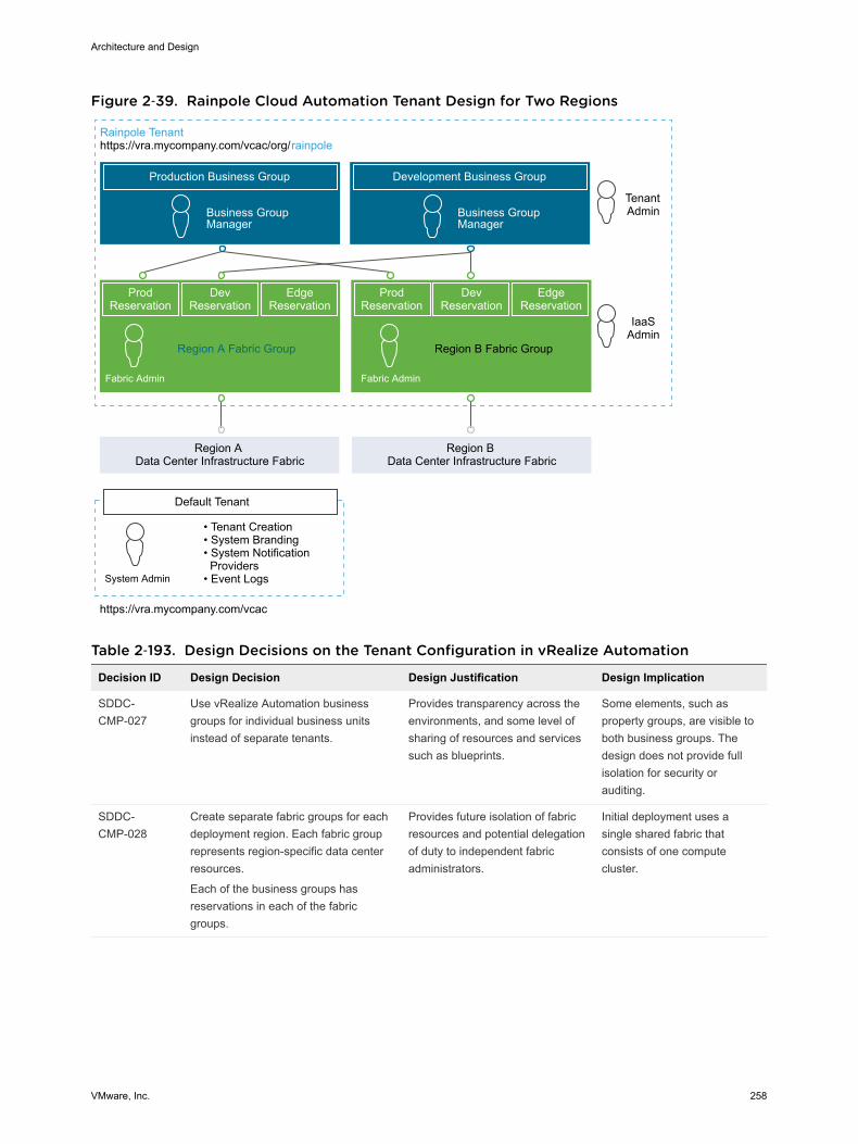
Figure 2‑39. Rainpole Cloud Automation Tenant Design for Two Regions
Production Business Group
Rainpole Tenanthttps://vra.mycompany.com/vcac/org/rainpole
Business Group Manager
Development Business Group
TenantAdminBusiness Group
Manager
Fabric Admin
IaaSAdmin
ProdReservation
DevReservation
EdgeReservation
Region A Fabric Group
ProdReservation
DevReservation
EdgeReservation
Region B Fabric Group
Region A Data Center Infrastructure Fabric
Region B Data Center Infrastructure Fabric
https://vra.mycompany.com/vcac
• Tenant Creation• System Branding• System Notification Providers• Event LogsSystem Admin
Default Tenant
Fabric Admin
Table 2‑193. Design Decisions on the Tenant Configuration in vRealize Automation
Decision ID Design Decision Design Justification Design Implication
SDDC-CMP-027
Use vRealize Automation businessgroups for individual business unitsinstead of separate tenants.
Provides transparency across theenvironments, and some level ofsharing of resources and servicessuch as blueprints.
Some elements, such asproperty groups, are visible toboth business groups. Thedesign does not provide fullisolation for security orauditing.
SDDC-CMP-028
Create separate fabric groups for eachdeployment region. Each fabric grouprepresents region-specific data centerresources.
Each of the business groups hasreservations in each of the fabricgroups.
Provides future isolation of fabricresources and potential delegationof duty to independent fabricadministrators.
Initial deployment uses asingle shared fabric thatconsists of one computecluster.
Architecture and Design
VMware, Inc. 258
Table 2‑193. Design Decisions on the Tenant Configuration in vRealize Automation(Continued)
Decision ID Design Decision Design Justification Design Implication
SDDC-CMP-029
Let only the system administratoraccess the default tenant for managingtenants and modifying system-wideconfigurations.
Isolates the default tenant fromindividual tenant configurations.
Each tenant administrator isresponsible for managing theirown tenant configuration.
SDDC-CMP-030
Evaluate your internal organizationalstructure and workload needs.Configure business groups,reservations, service catalogs, andblueprints in the vRealize Automationinstance according to yourorganization's needs.
The tenant configuration ofvRealize Automation representsthe needs of your organization.
In this design, use the guidancefor the Rainpole tenant as astarting point.
Partners and customers mustevaluate their business needs.
Service Catalog in vRealize Automation
The service catalog provides a common interface for consumers of IT services to use to request andmanage the services and resources they need.
A tenant administrator or service architect can specify information about the service catalog, such as theservice hours, support team, and change window. While the catalog does not enforce service-levelagreements on services, the information about the service hours, support team, and change window isavailable to business users browsing the service catalog.
Catalog Items
Users can browse the service catalog for catalog items they are entitled to request. For some catalogitems, a request results in the provisioning of an item that the user can manage. For example, the usercan request a virtual machine with Windows 2012 preinstalled, and then manage that virtual machineafter it has been provisioned.
Tenant administrators define new catalog items and publish them to the service catalog. The tenantadministrator can then manage the presentation of catalog items to the consumer and entitle new items toconsumers. To make the catalog item available to users, a tenant administrator must entitle the item tothe users and groups who should have access to it. For example, some catalog items may be availableonly to a specific business group, while other catalog items may be shared between business groupsusing the same tenant. The administrator determines what catalog items are available to different usersbased on their job functions, departments, or location.
Typically, a catalog item is defined in a blueprint, which provides a complete specification of the resourceto be provisioned and the process to initiate when the item is requested. It also defines the optionsavailable to a requester of the item, such as virtual machine specifications or lease duration, or anyadditional information that the requester is prompted to provide when submitting the request.
Machine Blueprints in vRealize Automation
A machine blueprint is the complete specification for a virtual, cloud or physical machine. A machineblueprint determines the machine's attributes, how it is provisioned, and its policy and managementsettings. Machine blueprints are published as catalog items in the service catalog.
Architecture and Design
VMware, Inc. 259
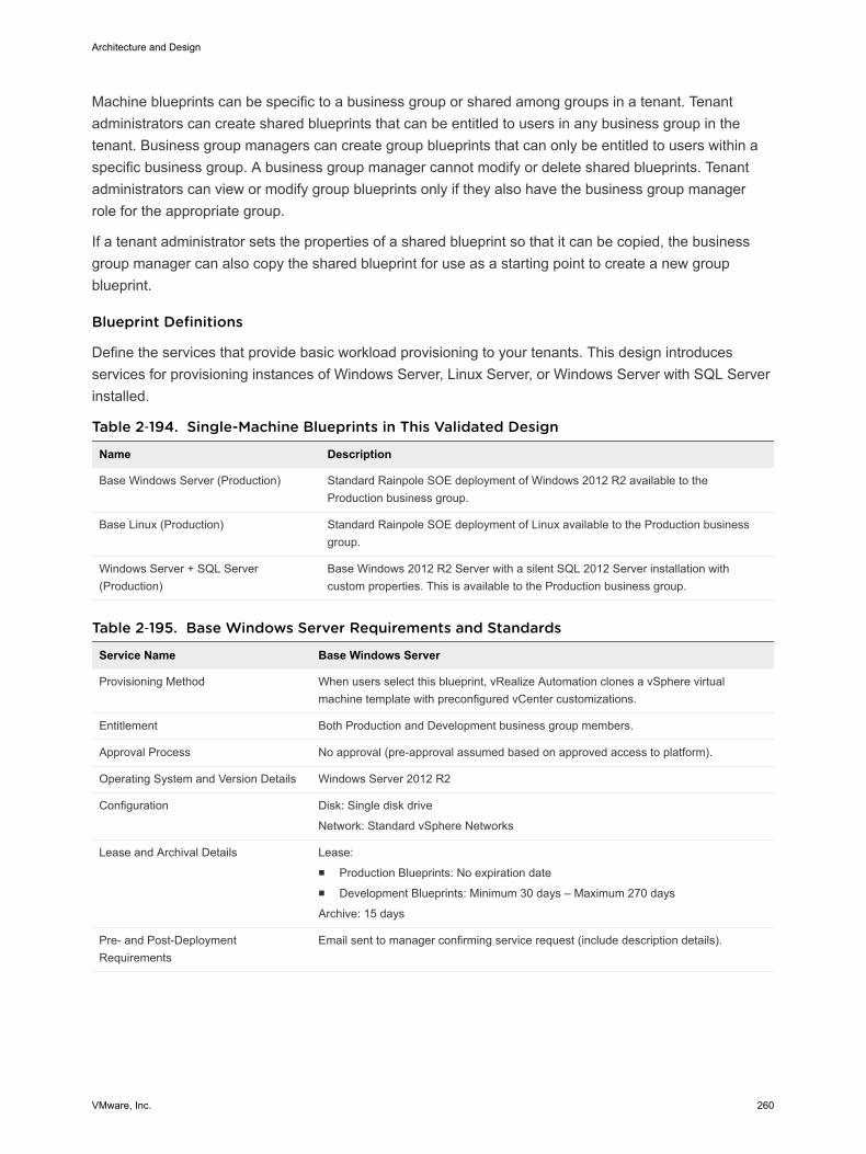
Machine blueprints can be specific to a business group or shared among groups in a tenant. Tenantadministrators can create shared blueprints that can be entitled to users in any business group in thetenant. Business group managers can create group blueprints that can only be entitled to users within aspecific business group. A business group manager cannot modify or delete shared blueprints. Tenantadministrators can view or modify group blueprints only if they also have the business group managerrole for the appropriate group.
If a tenant administrator sets the properties of a shared blueprint so that it can be copied, the businessgroup manager can also copy the shared blueprint for use as a starting point to create a new groupblueprint.
Blueprint Definitions
Define the services that provide basic workload provisioning to your tenants. This design introducesservices for provisioning instances of Windows Server, Linux Server, or Windows Server with SQL Serverinstalled.
Table 2‑194. Single-Machine Blueprints in This Validated Design
Name Description
Base Windows Server (Production) Standard Rainpole SOE deployment of Windows 2012 R2 available to theProduction business group.
Base Linux (Production) Standard Rainpole SOE deployment of Linux available to the Production businessgroup.
Windows Server + SQL Server(Production)
Base Windows 2012 R2 Server with a silent SQL 2012 Server installation withcustom properties. This is available to the Production business group.
Table 2‑195. Base Windows Server Requirements and Standards
Service Name Base Windows Server
Provisioning Method When users select this blueprint, vRealize Automation clones a vSphere virtualmachine template with preconfigured vCenter customizations.
Entitlement Both Production and Development business group members.
Approval Process No approval (pre-approval assumed based on approved access to platform).
Operating System and Version Details Windows Server 2012 R2
Configuration Disk: Single disk drive
Network: Standard vSphere Networks
Lease and Archival Details Lease:n Production Blueprints: No expiration daten Development Blueprints: Minimum 30 days – Maximum 270 days
Archive: 15 days
Pre- and Post-DeploymentRequirements
Email sent to manager confirming service request (include description details).
Architecture and Design
VMware, Inc. 260
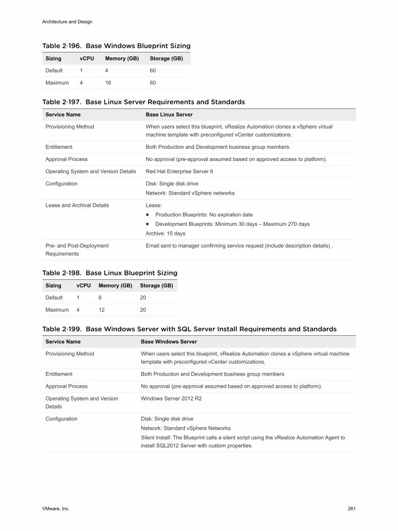
Table 2‑196. Base Windows Blueprint Sizing
Sizing vCPU Memory (GB) Storage (GB)
Default 1 4 60
Maximum 4 16 60
Table 2‑197. Base Linux Server Requirements and Standards
Service Name Base Linux Server
Provisioning Method When users select this blueprint, vRealize Automation clones a vSphere virtualmachine template with preconfigured vCenter customizations.
Entitlement Both Production and Development business group members.
Approval Process No approval (pre-approval assumed based on approved access to platform).
Operating System and Version Details Red Hat Enterprise Server 6
Configuration Disk: Single disk drive
Network: Standard vSphere networks
Lease and Archival Details Lease:n Production Blueprints: No expiration daten Development Blueprints: Minimum 30 days – Maximum 270 days
Archive: 15 days
Pre- and Post-DeploymentRequirements
Email sent to manager confirming service request (include description details) .
Table 2‑198. Base Linux Blueprint Sizing
Sizing vCPU Memory (GB) Storage (GB)
Default 1 6 20
Maximum 4 12 20
Table 2‑199. Base Windows Server with SQL Server Install Requirements and Standards
Service Name Base Windows Server
Provisioning Method When users select this blueprint, vRealize Automation clones a vSphere virtual machinetemplate with preconfigured vCenter customizations.
Entitlement Both Production and Development business group members
Approval Process No approval (pre-approval assumed based on approved access to platform).
Operating System and VersionDetails
Windows Server 2012 R2
Configuration Disk: Single disk drive
Network: Standard vSphere Networks
Silent Install: The Blueprint calls a silent script using the vRealize Automation Agent toinstall SQL2012 Server with custom properties.
Architecture and Design
VMware, Inc. 261
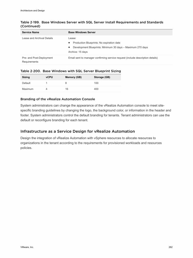
Table 2‑199. Base Windows Server with SQL Server Install Requirements and Standards(Continued)
Service Name Base Windows Server
Lease and Archival Details Lease:n Production Blueprints: No expiration daten Development Blueprints: Minimum 30 days – Maximum 270 days
Archive: 15 days
Pre- and Post-DeploymentRequirements
Email sent to manager confirming service request (include description details)
Table 2‑200. Base Windows with SQL Server Blueprint Sizing
Sizing vCPU Memory (GB) Storage (GB)
Default 1 8 100
Maximum 4 16 400
Branding of the vRealize Automation Console
System administrators can change the appearance of the vRealize Automation console to meet site-specific branding guidelines by changing the logo, the background color, or information in the header andfooter. System administrators control the default branding for tenants. Tenant administrators can use thedefault or reconfigure branding for each tenant.
Infrastructure as a Service Design for vRealize Automation Design the integration of vRealize Automation with vSphere resources to allocate resources toorganizations in the tenant according to the requirements for provisioned workloads and resourcespolicies.
Architecture and Design
VMware, Inc. 262
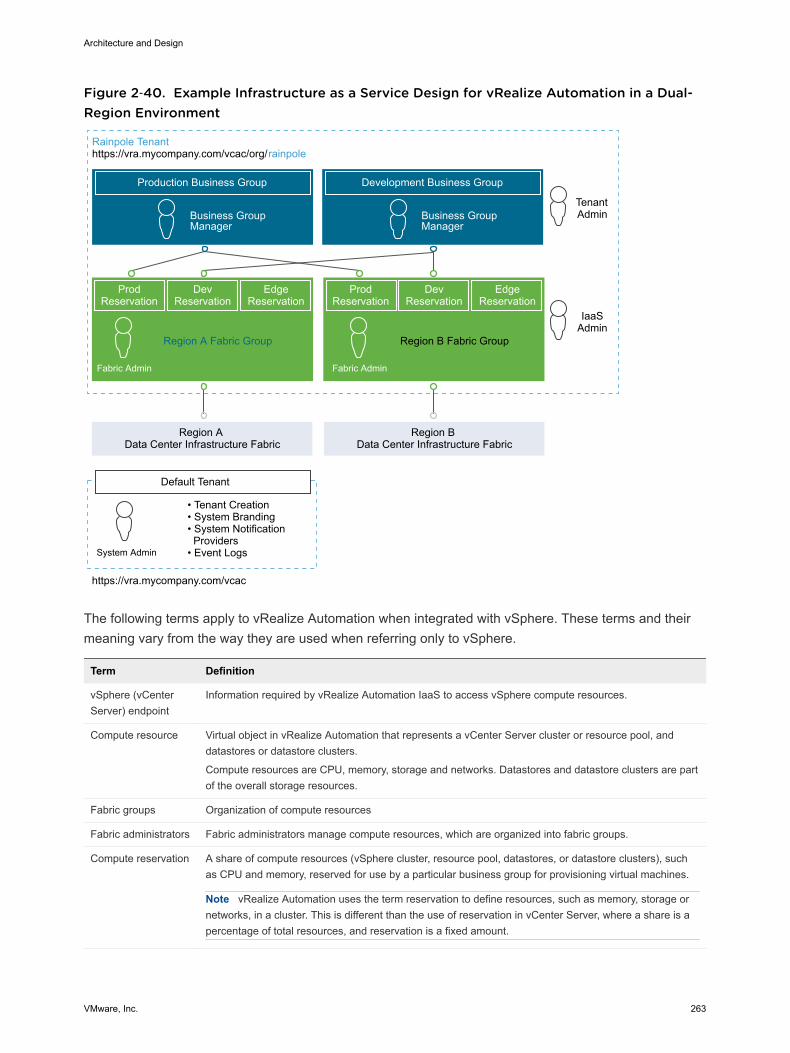
Figure 2‑40. Example Infrastructure as a Service Design for vRealize Automation in a Dual-Region Environment
Production Business Group
Rainpole Tenanthttps://vra.mycompany.com/vcac/org/rainpole
Business Group Manager
Development Business Group
TenantAdminBusiness Group
Manager
Fabric Admin
IaaSAdmin
ProdReservation
DevReservation
EdgeReservation
Region A Fabric Group
ProdReservation
DevReservation
EdgeReservation
Region B Fabric Group
Region A Data Center Infrastructure Fabric
Region B Data Center Infrastructure Fabric
https://vra.mycompany.com/vcac
• Tenant Creation• System Branding• System Notification Providers• Event LogsSystem Admin
Default Tenant
Fabric Admin
The following terms apply to vRealize Automation when integrated with vSphere. These terms and theirmeaning vary from the way they are used when referring only to vSphere.
Term Definition
vSphere (vCenterServer) endpoint
Information required by vRealize Automation IaaS to access vSphere compute resources.
Compute resource Virtual object in vRealize Automation that represents a vCenter Server cluster or resource pool, anddatastores or datastore clusters.
Compute resources are CPU, memory, storage and networks. Datastores and datastore clusters are partof the overall storage resources.
Fabric groups Organization of compute resources
Fabric administrators Fabric administrators manage compute resources, which are organized into fabric groups.
Compute reservation A share of compute resources (vSphere cluster, resource pool, datastores, or datastore clusters), suchas CPU and memory, reserved for use by a particular business group for provisioning virtual machines.
Note vRealize Automation uses the term reservation to define resources, such as memory, storage ornetworks, in a cluster. This is different than the use of reservation in vCenter Server, where a share is apercentage of total resources, and reservation is a fixed amount.
Architecture and Design
VMware, Inc. 263
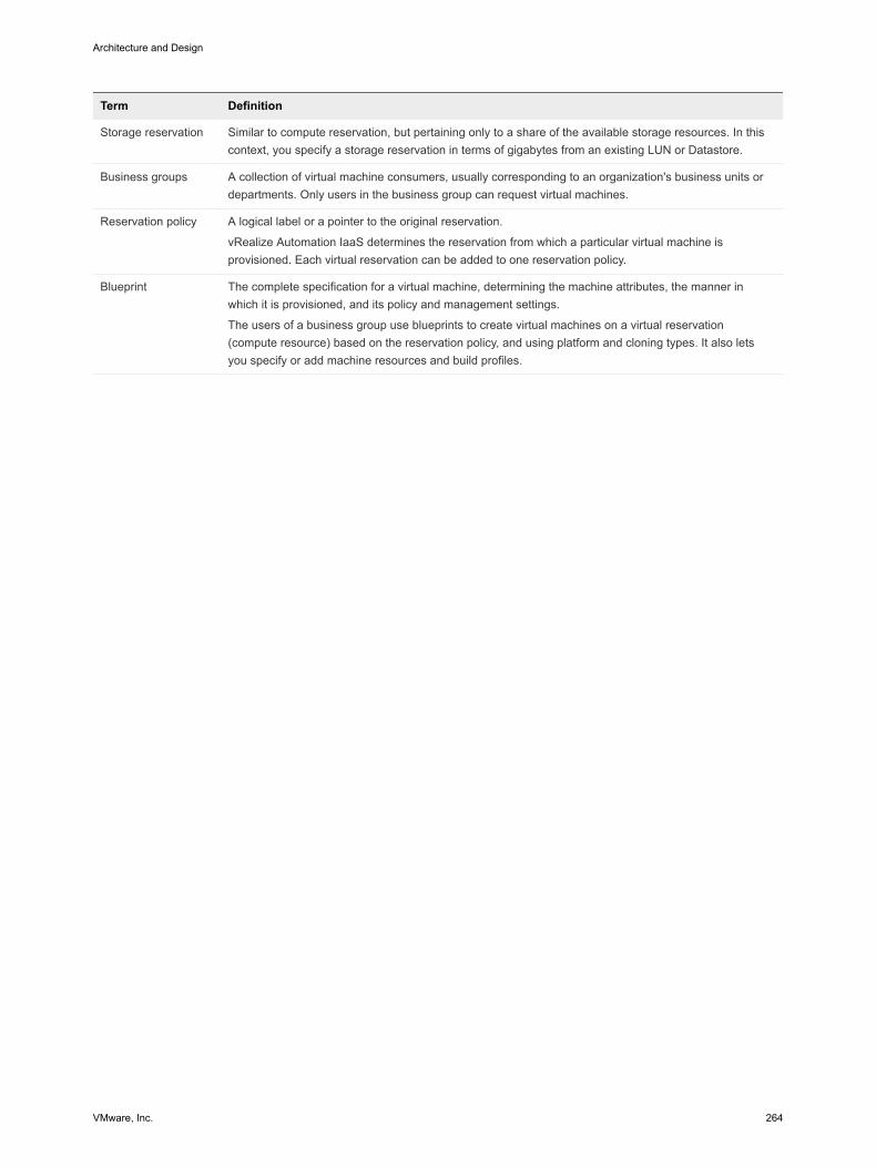
Term Definition
Storage reservation Similar to compute reservation, but pertaining only to a share of the available storage resources. In thiscontext, you specify a storage reservation in terms of gigabytes from an existing LUN or Datastore.
Business groups A collection of virtual machine consumers, usually corresponding to an organization's business units ordepartments. Only users in the business group can request virtual machines.
Reservation policy A logical label or a pointer to the original reservation.
vRealize Automation IaaS determines the reservation from which a particular virtual machine isprovisioned. Each virtual reservation can be added to one reservation policy.
Blueprint The complete specification for a virtual machine, determining the machine attributes, the manner inwhich it is provisioned, and its policy and management settings.
The users of a business group use blueprints to create virtual machines on a virtual reservation(compute resource) based on the reservation policy, and using platform and cloning types. It also letsyou specify or add machine resources and build profiles.
Architecture and Design
VMware, Inc. 264
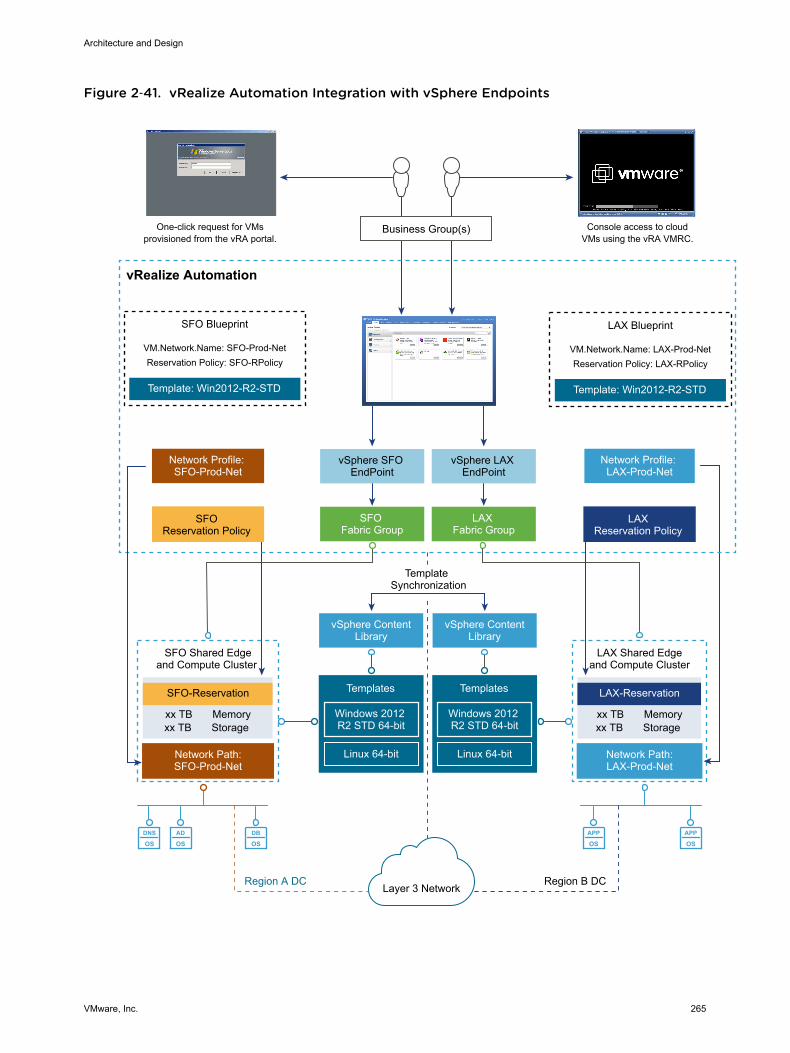
Figure 2‑41. vRealize Automation Integration with vSphere Endpoints
DNS
OSAD
OSDB
OSAPP
OSAPP
OS
Business Group(s)One-click request for VMsprovisioned from the vRA portal.
Console access to cloudVMs using the vRA VMRC.
vSphere SFO EndPoint
vSphere LAX EndPoint
SFO Fabric Group
LAX Fabric Group
SFO Blueprint
VM.Network.Name: SFO-Prod-NetReservation Policy: SFO-RPolicy
Template: Win2012-R2-STD
LAX Blueprint
VM.Network.Name: LAX-Prod-NetReservation Policy: LAX-RPolicy
Template: Win2012-R2-STD
Network Profile: SFO-Prod-Net
Network Profile: LAX-Prod-Net
SFO Reservation Policy
LAX Reservation Policy
vRealize Automation
vSphere ContentLibrary
Templates
Windows 2012 R2 STD 64-bit
Linux 64-bit
Template Synchronization
vSphere ContentLibrary
Templates
Windows 2012 R2 STD 64-bit
Linux 64-bitNetwork Path:SFO-Prod-Net
SFO-Reservation
SFO Shared Edgeand Compute Cluster
xx TB Memoryxx TB Storage
Network Path:LAX-Prod-Net
LAX-Reservation
LAX Shared Edgeand Compute Cluster
xx TB Memoryxx TB Storage
Layer 3 NetworkRegion A DC Region B DC
Architecture and Design
VMware, Inc. 265
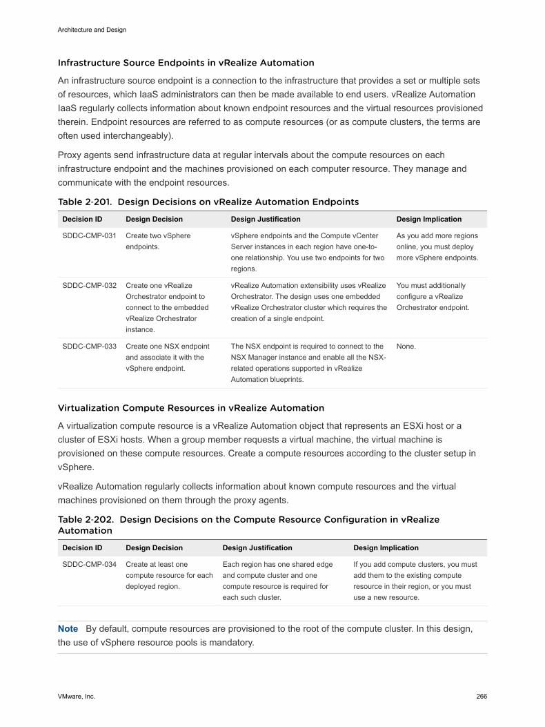
Infrastructure Source Endpoints in vRealize Automation
An infrastructure source endpoint is a connection to the infrastructure that provides a set or multiple setsof resources, which IaaS administrators can then be made available to end users. vRealize AutomationIaaS regularly collects information about known endpoint resources and the virtual resources provisionedtherein. Endpoint resources are referred to as compute resources (or as compute clusters, the terms areoften used interchangeably).
Proxy agents send infrastructure data at regular intervals about the compute resources on eachinfrastructure endpoint and the machines provisioned on each computer resource. They manage andcommunicate with the endpoint resources.
Table 2‑201. Design Decisions on vRealize Automation Endpoints
Decision ID Design Decision Design Justification Design Implication
SDDC-CMP-031 Create two vSphereendpoints.
vSphere endpoints and the Compute vCenterServer instances in each region have one-to-one relationship. You use two endpoints for tworegions.
As you add more regionsonline, you must deploymore vSphere endpoints.
SDDC-CMP-032 Create one vRealizeOrchestrator endpoint toconnect to the embeddedvRealize Orchestratorinstance.
vRealize Automation extensibility uses vRealizeOrchestrator. The design uses one embeddedvRealize Orchestrator cluster which requires thecreation of a single endpoint.
You must additionallyconfigure a vRealizeOrchestrator endpoint.
SDDC-CMP-033 Create one NSX endpointand associate it with thevSphere endpoint.
The NSX endpoint is required to connect to theNSX Manager instance and enable all the NSX-related operations supported in vRealizeAutomation blueprints.
None.
Virtualization Compute Resources in vRealize Automation
A virtualization compute resource is a vRealize Automation object that represents an ESXi host or acluster of ESXi hosts. When a group member requests a virtual machine, the virtual machine isprovisioned on these compute resources. Create a compute resources according to the cluster setup invSphere.
vRealize Automation regularly collects information about known compute resources and the virtualmachines provisioned on them through the proxy agents.
Table 2‑202. Design Decisions on the Compute Resource Configuration in vRealizeAutomation
Decision ID Design Decision Design Justification Design Implication
SDDC-CMP-034 Create at least onecompute resource for eachdeployed region.
Each region has one shared edgeand compute cluster and onecompute resource is required foreach such cluster.
If you add compute clusters, you mustadd them to the existing computeresource in their region, or you mustuse a new resource.
Note By default, compute resources are provisioned to the root of the compute cluster. In this design,the use of vSphere resource pools is mandatory.
Architecture and Design
VMware, Inc. 266

Fabric Groups in vRealize Automation
A fabric group is a logical container of several compute resources, and can be managed by fabricadministrators. Plan fabric groups according to the number of regions in your SDDC.
Table 2‑203. Design Decisions on Fabric Groups in vRealize Automation
Decision ID Design Decision Design Justification Design Implication
SDDC-CMP-035 Create a fabric group for eachregion and include all the computeresources and edge resources inthat region.
To enable region-specificprovisioning, you must create afabric group in each region.
If you add compute clusters to aregion, you must add them to thefabric group.
Business Groups in vRealize Automation
A business group is a collection of machine consumers, often corresponding to a line of business,department, or other organizational unit. To request machines, a vRealize Automation user must belongto at least one business group. Each group has access to a set of local blueprints used to requestmachines.
Business groups have the following characteristics:
n A group must have at least one business group manager, who maintains blueprints for the group andapproves machine requests.
n Groups can contain support users, who can request and manage machines on behalf of other groupmembers.
n A vRealize Automation user can be a member of more than one business group, and can havedifferent roles in each group.
Reservations in vRealize Automation
A reservation is a share of available memory, CPU and storage one compute resource that is reserved foruse by a particular fabric group. Each reservation is for one fabric group only but the relationship is many-to-many. A fabric group might have multiple reservations on one compute resource, or reservations onmultiple compute resources, or both. A reservation must include a vSphere resource pool.
Shared Edge and Compute Clusters and Resource Pools
While reservations provide a method to allocate a portion of the cluster memory or storage in vRealizeAutomation, reservations do not control how CPU and memory are allocated during periods of contentionon the underlying vSphere compute resources. Use vSphere resource pools to control the allocation ofCPU and memory during time of resource contention on the underlying host. To fully use the mechanismof resource pools for provisioning of workloads, all VMs must be deployed on one of the followingresource pools.
Architecture and Design
VMware, Inc. 267

Table 2‑204. Resource pool details
Resource Pool Object Types
sfo01-w01rp-sddc-edge NSX Edge components at the data center level. Place userworkload in other resource pools.
sfo01-w01rp-user-edge Statically or dynamically deployed NSX components such asNSX Edge gateways or load balancers which serve specificcustomer workloads
sfo01-w01rp-user-vm Statically or dynamically deployed virtual machines such asWindows instances, Linux instances, databases, etc., whichcontain specific customer workloads
Table 2‑205. Design Decisions on Reservations in vRealize Automation
Decision ID Design Decision Design Justification Design Implication
SDDC-CMP-036
Create at least onevRealize Automationreservation for eachbusiness group at eachregion.
In this design, each resource cluster has tworeservations: one for production and one fordevelopment, so that you can provision bothproduction and development workloads on thecluster.
Because production anddevelopment share computeresources, the developmentbusiness group must be limitedto a fixed amount of resources.
SDDC-CMP-037
Create at least onevRealize Automationreservation for edgeresources in each region.
NSX can create edge services gateways ondemand and place them on the shared edgeand compute cluster.
The workload reservation mustdefine the edge reservation inthe network settings.
SDDC-CMP-038
Configure all vRealizeAutomation workloads touse the sfo01-w01rp-user-vm resource pool.
You introduce control over the resourcesallocated to the tenant application workloads.As a result, using another resource pool youcan dedicate more compute resources to theNSX networking components that providenetworking to the workloads.
Workloads provisioned at the root resourcepool level receive more resources than thosein child resource pools. In contentionsituations, virtual machines might receiveinsufficient resources.
Cloud administrators mustensure that all workloadreservations are configuredwith the right resource pool.You can have a single resourcepool for both production anddevelopment workloads, or tworesource pools, one dedicatedfor the Development BusinessGroup and one dedicated forthe Production Business Group.
SDDC-CMP-039
Configure vRealizeAutomation reservations fordynamically provisionedNSX Edge components(routed gateway) to use thesfo01-w01rp-user-edgeresource pool.
You dedicate compute resources to NSXnetworking components. You must assign avSphere resource pool to end-user deployedNSX Edge components.
Workloads provisioned at the root resourcepool level receives more resources than childresource pools, which might starve thosevirtual machines in contention situations.
Cloud administrators mustverify that all workloadreservations are configuredwith the right resource pool.
SDDC-CMP-040
All vSphere resource poolsfor edge or computeworkloads must be createdat the root level.
Do not nest resource pools.
Nesting of resource pools can createadministratively complex resource calculationsthat might result in unintended under- or over-allocation of resources during contentionsituations.
None.
Architecture and Design
VMware, Inc. 268
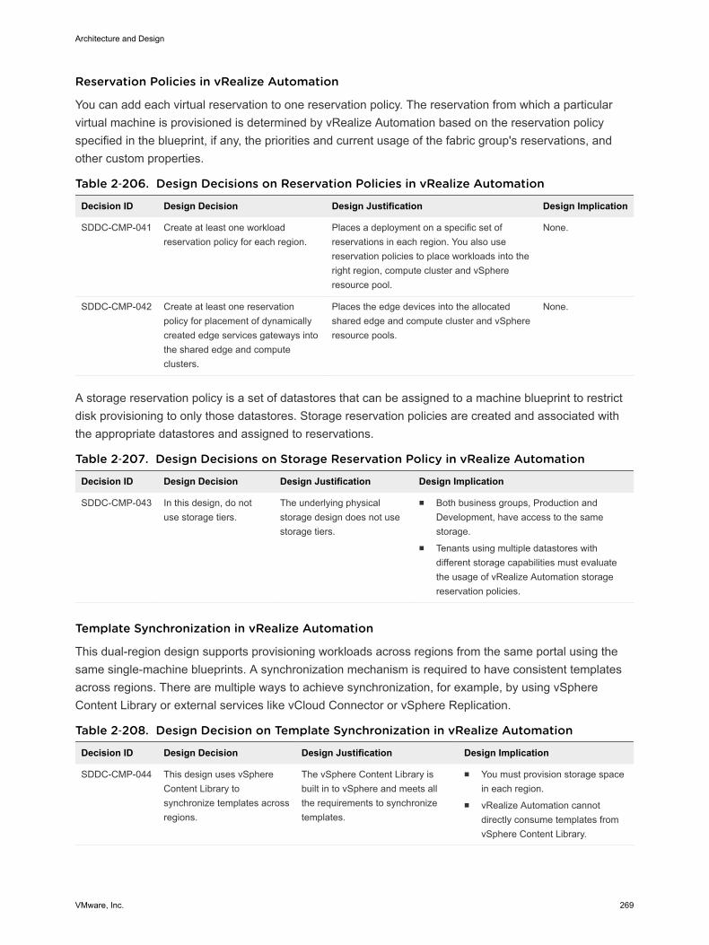
Reservation Policies in vRealize Automation
You can add each virtual reservation to one reservation policy. The reservation from which a particularvirtual machine is provisioned is determined by vRealize Automation based on the reservation policyspecified in the blueprint, if any, the priorities and current usage of the fabric group's reservations, andother custom properties.
Table 2‑206. Design Decisions on Reservation Policies in vRealize Automation
Decision ID Design Decision Design Justification Design Implication
SDDC-CMP-041 Create at least one workloadreservation policy for each region.
Places a deployment on a specific set ofreservations in each region. You also usereservation policies to place workloads into theright region, compute cluster and vSphereresource pool.
None.
SDDC-CMP-042 Create at least one reservationpolicy for placement of dynamicallycreated edge services gateways intothe shared edge and computeclusters.
Places the edge devices into the allocatedshared edge and compute cluster and vSphereresource pools.
None.
A storage reservation policy is a set of datastores that can be assigned to a machine blueprint to restrictdisk provisioning to only those datastores. Storage reservation policies are created and associated withthe appropriate datastores and assigned to reservations.
Table 2‑207. Design Decisions on Storage Reservation Policy in vRealize Automation
Decision ID Design Decision Design Justification Design Implication
SDDC-CMP-043 In this design, do notuse storage tiers.
The underlying physicalstorage design does not usestorage tiers.
n Both business groups, Production andDevelopment, have access to the samestorage.
n Tenants using multiple datastores withdifferent storage capabilities must evaluatethe usage of vRealize Automation storagereservation policies.
Template Synchronization in vRealize Automation
This dual-region design supports provisioning workloads across regions from the same portal using thesame single-machine blueprints. A synchronization mechanism is required to have consistent templatesacross regions. There are multiple ways to achieve synchronization, for example, by using vSphereContent Library or external services like vCloud Connector or vSphere Replication.
Table 2‑208. Design Decision on Template Synchronization in vRealize Automation
Decision ID Design Decision Design Justification Design Implication
SDDC-CMP-044 This design uses vSphereContent Library tosynchronize templates acrossregions.
The vSphere Content Library isbuilt in to vSphere and meets allthe requirements to synchronizetemplates.
n You must provision storage spacein each region.
n vRealize Automation cannotdirectly consume templates fromvSphere Content Library.
Architecture and Design
VMware, Inc. 269
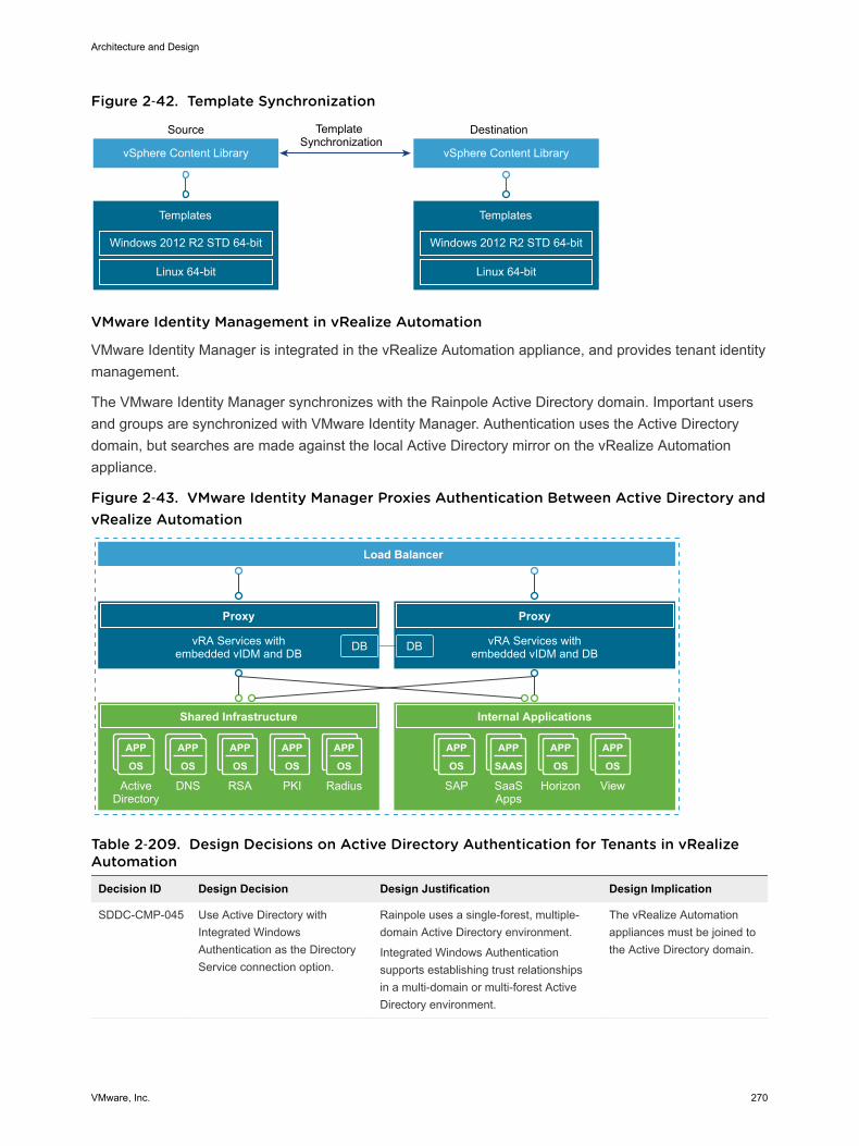
Figure 2‑42. Template Synchronization
vSphere Content Library
Source
Templates
Windows 2012 R2 STD 64-bit
Linux 64-bit
DestinationTemplate Synchronization
vSphere Content Library
Templates
Windows 2012 R2 STD 64-bit
Linux 64-bit
VMware Identity Management in vRealize Automation
VMware Identity Manager is integrated in the vRealize Automation appliance, and provides tenant identitymanagement.
The VMware Identity Manager synchronizes with the Rainpole Active Directory domain. Important usersand groups are synchronized with VMware Identity Manager. Authentication uses the Active Directorydomain, but searches are made against the local Active Directory mirror on the vRealize Automationappliance.
Figure 2‑43. VMware Identity Manager Proxies Authentication Between Active Directory andvRealize Automation
APP
OS
APP
SAAS
APP
OS
APP
OS
APP
OS
APP
OS
APP
OS
APP
OS
APP
OS
Proxy
Internal Applications
vRA Services withembedded vIDM and DB
SAP SaaSApps
Horizon View
Load Balancer
Proxy
Shared Infrastructure
vRA Services withembedded vIDM and DB
Active Directory
DNS RSA PKI Radius
DB DB
Table 2‑209. Design Decisions on Active Directory Authentication for Tenants in vRealizeAutomation
Decision ID Design Decision Design Justification Design Implication
SDDC-CMP-045 Use Active Directory withIntegrated WindowsAuthentication as the DirectoryService connection option.
Rainpole uses a single-forest, multiple-domain Active Directory environment.
Integrated Windows Authenticationsupports establishing trust relationshipsin a multi-domain or multi-forest ActiveDirectory environment.
The vRealize Automationappliances must be joined tothe Active Directory domain.
Architecture and Design
VMware, Inc. 270
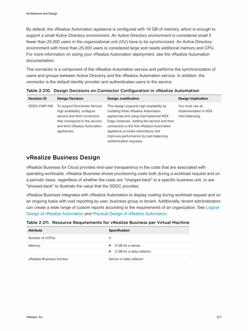
By default, the vRealize Automation appliance is configured with 18 GB of memory, which is enough tosupport a small Active Directory environment. An Active Directory environment is considered small iffewer than 25,000 users in the organizational unit (OU) have to be synchronized. An Active Directoryenvironment with more than 25,000 users is considered large and needs additional memory and CPU.For more information on sizing your vRealize Automation deployment, see the vRealize Automationdocumentation.
The connector is a component of the vRealize Automation service and performs the synchronization ofusers and groups between Active Directory and the vRealize Automation service. In addition, theconnector is the default identity provider and authenticates users to the service.
Table 2‑210. Design Decisions on Connector Configuration in vRealize Automation
Decision ID Design Decision Design Justification Design Implication
SDDC-CMP-046 To support Directories Servicehigh availability, configuresecond and third connectorsthat correspond to the secondand third vRealize Automationappliances.
This design supports high availability byinstalling three vRealize Automationappliances and using load-balanced NSXEdge instances. Adding the second and thirdconnectors to the first vRealize Automationappliance provides redundancy andimproves performance by load balancingauthentication requests.
You must use animplementation in NSXload balancing.
vRealize Business Design vRealize Business for Cloud provides end-user transparency in the costs that are associated withoperating workloads. vRealize Business shows provisioning costs both during a workload request and ona periodic basis, regardless of whether the costs are "charged-back" to a specific business unit, or are"showed-back" to illustrate the value that the SDDC provides.
vRealize Business integrates with vRealize Automation to display costing during workload request and onan ongoing basis with cost reporting by user, business group or tenant. Additionally, tenant administratorscan create a wide range of custom reports according to the requirements of an organization. See LogicalDesign of vRealize Automation and Physical Design of vRealize Automation.
Table 2‑211. Resource Requirements for vRealize Business per Virtual Machine
Attribute Specification
Number of vCPUs 4
Memory n 8 GB for a servern 2 GB for a data collector
vRealize Business function Server or data collector
Architecture and Design
VMware, Inc. 271
Table 2‑212. Design Decision on vRealize Business
Decision ID Design Decision Design Justification Design Implication
SDDC-CMP-047
Deploy vRealize Business aspart of the Cloud ManagementPlatform and integrate it withvRealize Automation.
You introduce tenant and workloadcostings.
You must deploy moreappliances: for the vRealizeBusiness server and for datacollectors.
SDDC-CMP-048
Use the default vRealizeBusiness appliance size of 8GB. For the vRealize Businessdata collectors, select a reducedmemory size of 2 GB.
The default appliance size of vRealizeBusiness supports the design objectiveof 10,000 VMs.
Data collectors do not run serverservice, and can run on 2 GB of RAM.
None.
SDDC-CMP-049
Use the default vRealizeBusiness reference costingdatabase.
The default reference costing is basedon industry information and isperiodically updated.
Default reference costing mightnot accurately represent actualcustomer costs. The vRealizeBusiness server requires Internetaccess to periodically update thereference database.
SDDC-CMP-050
Deploy vRealize Business as athree-VM architecture withremote data collectors in RegionA and Region B.
For best performance, the vRealizeBusiness collectors must be regionallylocal to the resource which they areconfigured to collect data from. Becausethis design supports disaster recovery,the data collectors can reside in RegionA and Region B.
If the environment does not havedisaster recovery support, youmust deploy an additionalappliance for the remote datacollector, although the vRealizeBusiness server can handle theload on its own.
SDDC-CMP-051
Deploy the vRealize Businessserver VM in the cross-regionlogical network.
The vRealize Business deploymentdepends on vRealize Automation.During a disaster recovery event,vRealize Business migrates withvRealize Automation.
None.
SDDC-CMP-052
Deploy a vRealize Businessremote data collector VM ineach region-specific logicalnetwork.
vRealize Business remote data collectoris a region-specific installation. During adisaster recovery event, the remotecollector does not need to migrate withvRealize Automation.
The communication with vCenterServer involves an extra Layer 3hop through an NSX Edgedevice.
vRealize Orchestrator Design VMware vRealize Orchestrator is a development and process automation platform that provides a libraryof extensible workflows to allow you to create and run automated, configurable processes to manage theVMware vSphere infrastructure as well as other VMware and third-party technologies.
In this VMware Validated Design, vRealize Automation uses the vRealize Orchestrator plug-in to connectto vCenter Server for customized virtual machine provisioning and post-provisioning actions.
Architecture and Design
VMware, Inc. 272

Physical Design of vRealize Orchestrator This VMware Validated Design uses the vRealize Orchestrator instance that is embedded in the vRealizeAutomation Appliance, instead of using a dedicated or external vRealize Orchestrator instance. Usingembedded vRealize Orchestrator simplifies the deployment model and improves the operationalefficiency.
Table 2‑213. Design Decisions on vRealize Orchestrator
Decision ID Design Decision Design JustificationDesignImplication
SDDC-CMP-VRO-001
Use the internalvRealize Orchestratorinstances that areembedded in thedeployed vRealizeAutomation instances.
n The use of embedded vRealize Orchestrator has thefollowing advantages:
n Provides faster time to value.n Reduces the number of appliances to manage.n Provides easier upgrade path and better support-ability.n Improves performance.n Removes the need for an external database.n Overall simplification of the design leading to a reduced
number of appliances and enhanced support-ability.
Note Using the embedded instance of vRealize Orchestrator isapplicable in most use cases. However, refer to the productdocumentation to be aware of the cases where using theexternal vRealize Orchestrator is applicable.
None.
Authentication to vRealize Orchestrator
The embedded vRealize Orchestrator supports only vRealize Automation authentication method.
Table 2‑214. Design Decisions on the Directory Service of vRealize Orchestrator
Decision ID Design Decision Design Justification Design Implication
SDDC-CMP-VRO-002
Embedded vRealizeOrchestrator uses the vRealizeAutomation authentication.
The only authentication methodavailable.
None.
SDDC-CMP-VRO-003
Configure vRealizeOrchestrator to use thevRealize Automation customertenant (rainpole) forauthentication.
The vRealize Automation defaulttenant users are only administrativeusers. By connecting to the customertenant, workflows running onvRealize Orchestrator can run withend-user granted permissions.
End users who run vRealizeOrchestrator workflows arerequired to have permissions onthe vRealize Orchestrator server.
Some plug-ins might not functioncorrectly using vRealizeAutomation authentication.
SDDC-CMP-VRO-004
Each vRealize Orchestratorinstance is associated withonly one customer tenant.
To provide best security andsegregation between potentialtenants, vRealize Orchestratorinstance is associated with a singletenant.
If additional vRealize AutomationTenants are configured, additionalvRealize Orchestrator installationsare needed.
Architecture and Design
VMware, Inc. 273
Network Ports for vRealize Orchestrator
vRealize Orchestrator uses specific network ports to communicate with other systems. The ports areconfigured with a default value, but you can change the defaults at any time. When you make changes,verify that all ports are available for use by your host. If necessary, open these ports on any firewallsthrough which network traffic for the relevant components flows.
Incoming Communication Ports
Set default network ports and configure your firewall to allow incoming TCP connections. Other ports maybe required if you are using custom plug-ins.
Table 2‑215. Default Inbound Ports of vRealize Orchestrator
Port Number Protocol Source Target Description
HTTPS server port 443 TCP End-user Webbrowser
Embedded vRealizeOrchestrator server
The SSL secured HTTP protocolused to connect to the vRealizeOrchestrator REST API.
vRealize ApplianceOrchestrator ControlCenter
8283 TCP End-user Webbrowser
vRealize Orchestratorconfiguration
The SSL access port for thecontrol center Web UI for vRealizeOrchestrator configuration.
External Communication Ports
Configure your firewall to allow outgoing connections using the external network ports so that vRealizeOrchestrator can communicate with external services.
Table 2‑216. Default External Communication Ports of vRealize Orchestrator
Port Number Protocol Source Target Description
LDAP 389 TCP vRealizeOrchestrator server
LDAP server Lookup port of your LDAPauthentication server.
LDAP using SSL 636 TCP vRealizeOrchestrator server
LDAP server Lookup port of your secure LDAPauthentication server.
LDAP usingGlobal Catalog
3268 TCP vRealizeOrchestrator server
Global Catalogserver
Port to which Microsoft Global Catalogserver queries are directed.
DNS 53 TCP vRealizeOrchestrator server
DNS server Name resolution
VMwarevCenter™ SingleSign-On server
7444 TCP vRealizeOrchestrator server
vCenter SingleSign-On server
Port used to communicate with thevCenter Single Sign-On server.
SMTP Server port 25 TCP vRealizeOrchestrator server
SMTP Server Port used for email notifications.
vCenter ServerAPI port
443 TCP vRealizeOrchestrator server
VMwarevCenter server
The vCenter Server API communicationport used by vRealize Orchestrator toobtain virtual infrastructure and virtualmachine information from theorchestrated vCenter Server instances.
Architecture and Design
VMware, Inc. 274
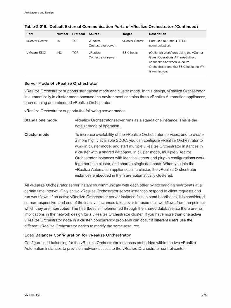
Table 2‑216. Default External Communication Ports of vRealize Orchestrator (Continued)
Port Number Protocol Source Target Description
vCenter Server 80 TCP vRealizeOrchestrator server
vCenter Server Port used to tunnel HTTPScommunication.
VMware ESXi 443 TCP vRealizeOrchestrator server
ESXi hosts (Optional) Workflows using the vCenterGuest Operations API need directconnection between vRealizeOrchestrator and the ESXi hosts the VMis running on.
Server Mode of vRealize Orchestrator
vRealize Orchestrator supports standalone mode and cluster mode. In this design, vRealize Orchestratoris automatically in cluster mode because the environment contains three vRealize Automation appliances,each running an embedded vRealize Orchestrator.
vRealize Orchestrator supports the following server modes.
Standalone mode vRealize Orchestrator server runs as a standalone instance. This is thedefault mode of operation.
Cluster mode To increase availability of the vRealize Orchestrator services, and to createa more highly available SDDC, you can configure vRealize Orchestrator towork in cluster mode, and start multiple vRealize Orchestrator instances ina cluster with a shared database. In cluster mode, multiple vRealizeOrchestrator instances with identical server and plug-in configurations worktogether as a cluster, and share a single database. When you join thevRealize Automation appliances in a cluster, the vRealize Orchestratorinstances embedded in them are automatically clustered.
All vRealize Orchestrator server instances communicate with each other by exchanging heartbeats at acertain time interval. Only active vRealize Orchestrator server instances respond to client requests andrun workflows. If an active vRealize Orchestrator server instance fails to send heartbeats, it is consideredas non-responsive, and one of the inactive instances takes over to resume all workflows from the point atwhich they are interrupted. The heartbeat is implemented through the shared database, so there are noimplications in the network design for a vRealize Orchestrator cluster. If you have more than one activevRealize Orchestrator node in a cluster, concurrency problems can occur if different users use thedifferent vRealize Orchestrator nodes to modify the same resource.
Load Balancer Configuration for vRealize Orchestrator
Configure load balancing for the vRealize Orchestrator instances embedded within the two vRealizeAutomation instances to provision network access to the vRealize Orchestrator control center.
Architecture and Design
VMware, Inc. 275
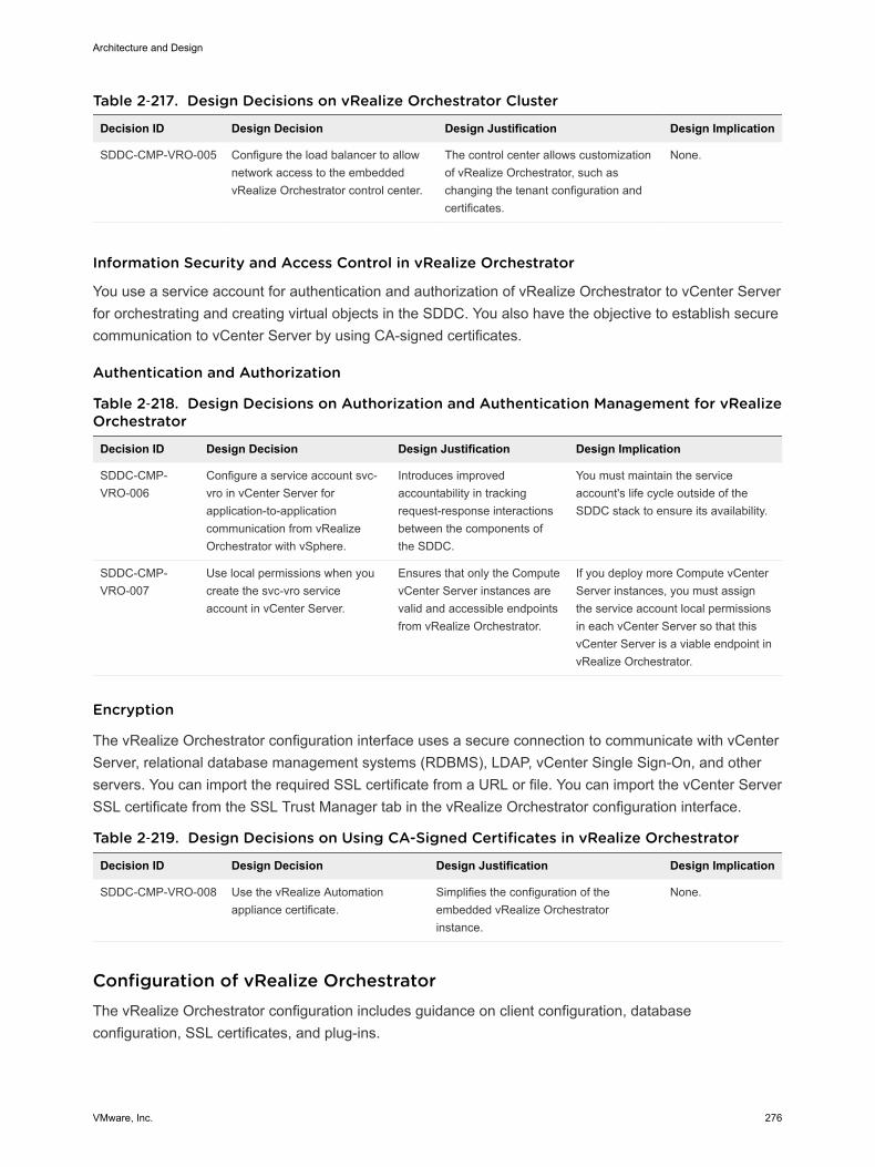
Table 2‑217. Design Decisions on vRealize Orchestrator Cluster
Decision ID Design Decision Design Justification Design Implication
SDDC-CMP-VRO-005 Configure the load balancer to allownetwork access to the embeddedvRealize Orchestrator control center.
The control center allows customizationof vRealize Orchestrator, such aschanging the tenant configuration andcertificates.
None.
Information Security and Access Control in vRealize Orchestrator
You use a service account for authentication and authorization of vRealize Orchestrator to vCenter Serverfor orchestrating and creating virtual objects in the SDDC. You also have the objective to establish securecommunication to vCenter Server by using CA-signed certificates.
Authentication and Authorization
Table 2‑218. Design Decisions on Authorization and Authentication Management for vRealizeOrchestrator
Decision ID Design Decision Design Justification Design Implication
SDDC-CMP-VRO-006
Configure a service account svc-vro in vCenter Server forapplication-to-applicationcommunication from vRealizeOrchestrator with vSphere.
Introduces improvedaccountability in trackingrequest-response interactionsbetween the components ofthe SDDC.
You must maintain the serviceaccount's life cycle outside of theSDDC stack to ensure its availability.
SDDC-CMP-VRO-007
Use local permissions when youcreate the svc-vro serviceaccount in vCenter Server.
Ensures that only the ComputevCenter Server instances arevalid and accessible endpointsfrom vRealize Orchestrator.
If you deploy more Compute vCenterServer instances, you must assignthe service account local permissionsin each vCenter Server so that thisvCenter Server is a viable endpoint invRealize Orchestrator.
Encryption
The vRealize Orchestrator configuration interface uses a secure connection to communicate with vCenterServer, relational database management systems (RDBMS), LDAP, vCenter Single Sign-On, and otherservers. You can import the required SSL certificate from a URL or file. You can import the vCenter ServerSSL certificate from the SSL Trust Manager tab in the vRealize Orchestrator configuration interface.
Table 2‑219. Design Decisions on Using CA-Signed Certificates in vRealize Orchestrator
Decision ID Design Decision Design Justification Design Implication
SDDC-CMP-VRO-008 Use the vRealize Automationappliance certificate.
Simplifies the configuration of theembedded vRealize Orchestratorinstance.
None.
Configuration of vRealize Orchestrator The vRealize Orchestrator configuration includes guidance on client configuration, databaseconfiguration, SSL certificates, and plug-ins.
Architecture and Design
VMware, Inc. 276
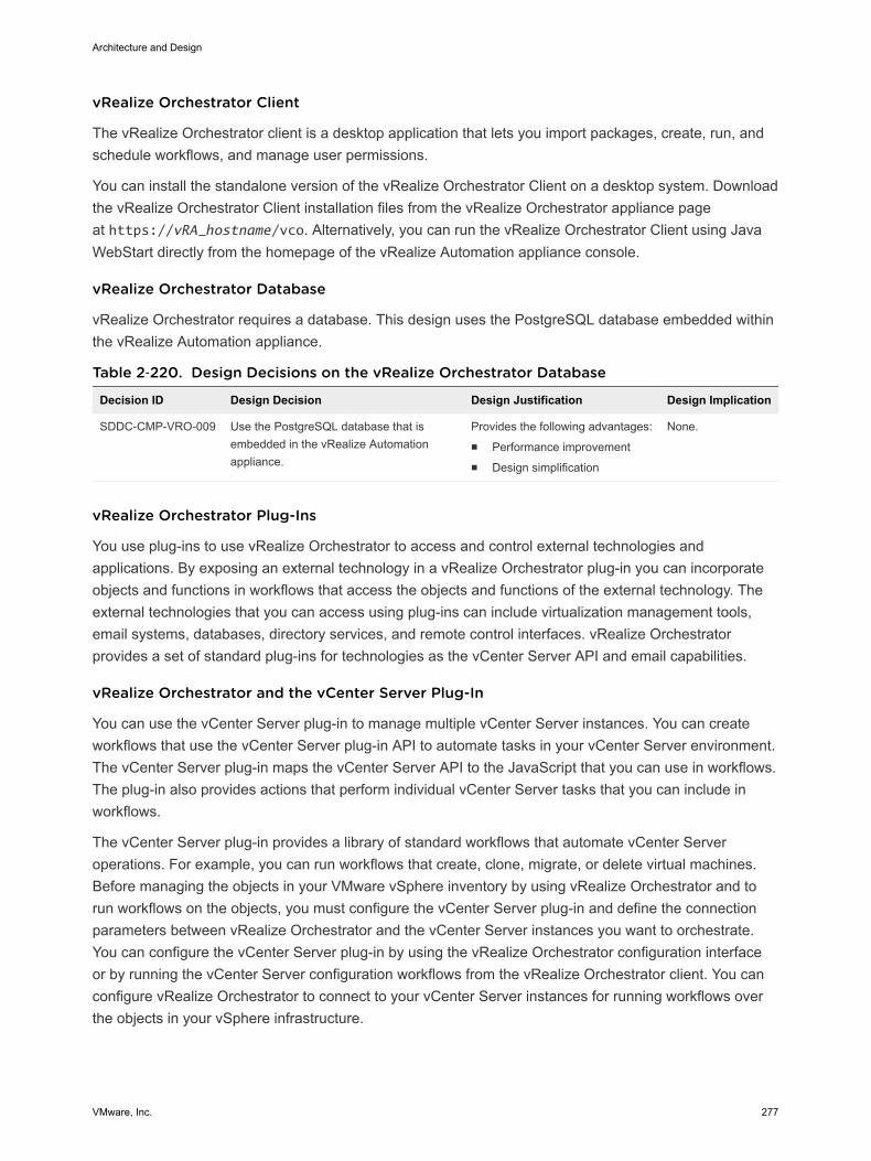
vRealize Orchestrator Client
The vRealize Orchestrator client is a desktop application that lets you import packages, create, run, andschedule workflows, and manage user permissions.
You can install the standalone version of the vRealize Orchestrator Client on a desktop system. Downloadthe vRealize Orchestrator Client installation files from the vRealize Orchestrator appliance pageat https://vRA_hostname/vco. Alternatively, you can run the vRealize Orchestrator Client using JavaWebStart directly from the homepage of the vRealize Automation appliance console.
vRealize Orchestrator Database
vRealize Orchestrator requires a database. This design uses the PostgreSQL database embedded withinthe vRealize Automation appliance.
Table 2‑220. Design Decisions on the vRealize Orchestrator Database
Decision ID Design Decision Design Justification Design Implication
SDDC-CMP-VRO-009 Use the PostgreSQL database that isembedded in the vRealize Automationappliance.
Provides the following advantages:n Performance improvementn Design simplification
None.
vRealize Orchestrator Plug-Ins
You use plug-ins to use vRealize Orchestrator to access and control external technologies andapplications. By exposing an external technology in a vRealize Orchestrator plug-in you can incorporateobjects and functions in workflows that access the objects and functions of the external technology. Theexternal technologies that you can access using plug-ins can include virtualization management tools,email systems, databases, directory services, and remote control interfaces. vRealize Orchestratorprovides a set of standard plug-ins for technologies as the vCenter Server API and email capabilities.
vRealize Orchestrator and the vCenter Server Plug-In
You can use the vCenter Server plug-in to manage multiple vCenter Server instances. You can createworkflows that use the vCenter Server plug-in API to automate tasks in your vCenter Server environment.The vCenter Server plug-in maps the vCenter Server API to the JavaScript that you can use in workflows.The plug-in also provides actions that perform individual vCenter Server tasks that you can include inworkflows.
The vCenter Server plug-in provides a library of standard workflows that automate vCenter Serveroperations. For example, you can run workflows that create, clone, migrate, or delete virtual machines.Before managing the objects in your VMware vSphere inventory by using vRealize Orchestrator and torun workflows on the objects, you must configure the vCenter Server plug-in and define the connectionparameters between vRealize Orchestrator and the vCenter Server instances you want to orchestrate.You can configure the vCenter Server plug-in by using the vRealize Orchestrator configuration interfaceor by running the vCenter Server configuration workflows from the vRealize Orchestrator client. You canconfigure vRealize Orchestrator to connect to your vCenter Server instances for running workflows overthe objects in your vSphere infrastructure.
Architecture and Design
VMware, Inc. 277
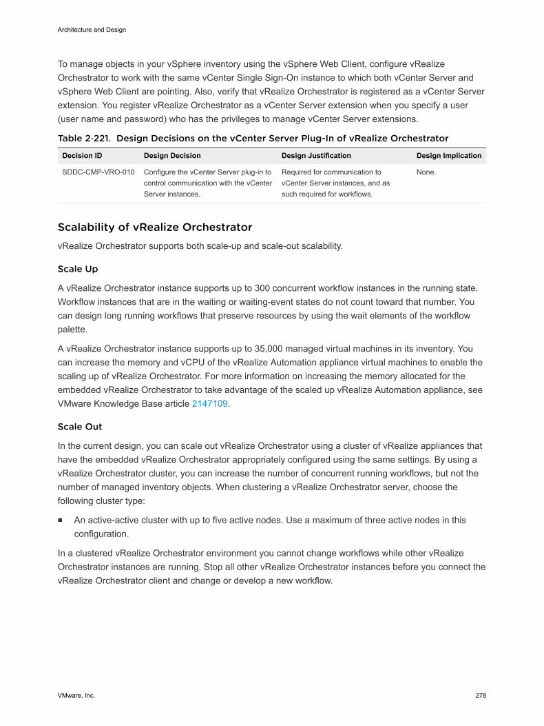
To manage objects in your vSphere inventory using the vSphere Web Client, configure vRealizeOrchestrator to work with the same vCenter Single Sign-On instance to which both vCenter Server andvSphere Web Client are pointing. Also, verify that vRealize Orchestrator is registered as a vCenter Serverextension. You register vRealize Orchestrator as a vCenter Server extension when you specify a user(user name and password) who has the privileges to manage vCenter Server extensions.
Table 2‑221. Design Decisions on the vCenter Server Plug-In of vRealize Orchestrator
Decision ID Design Decision Design Justification Design Implication
SDDC-CMP-VRO-010 Configure the vCenter Server plug-in tocontrol communication with the vCenterServer instances.
Required for communication tovCenter Server instances, and assuch required for workflows.
None.
Scalability of vRealize OrchestratorvRealize Orchestrator supports both scale-up and scale-out scalability.
Scale Up
A vRealize Orchestrator instance supports up to 300 concurrent workflow instances in the running state.Workflow instances that are in the waiting or waiting-event states do not count toward that number. Youcan design long running workflows that preserve resources by using the wait elements of the workflowpalette.
A vRealize Orchestrator instance supports up to 35,000 managed virtual machines in its inventory. Youcan increase the memory and vCPU of the vRealize Automation appliance virtual machines to enable thescaling up of vRealize Orchestrator. For more information on increasing the memory allocated for theembedded vRealize Orchestrator to take advantage of the scaled up vRealize Automation appliance, seeVMware Knowledge Base article 2147109.
Scale Out
In the current design, you can scale out vRealize Orchestrator using a cluster of vRealize appliances thathave the embedded vRealize Orchestrator appropriately configured using the same settings. By using avRealize Orchestrator cluster, you can increase the number of concurrent running workflows, but not thenumber of managed inventory objects. When clustering a vRealize Orchestrator server, choose thefollowing cluster type:
n An active-active cluster with up to five active nodes. Use a maximum of three active nodes in thisconfiguration.
In a clustered vRealize Orchestrator environment you cannot change workflows while other vRealizeOrchestrator instances are running. Stop all other vRealize Orchestrator instances before you connect thevRealize Orchestrator client and change or develop a new workflow.
Architecture and Design
VMware, Inc. 278
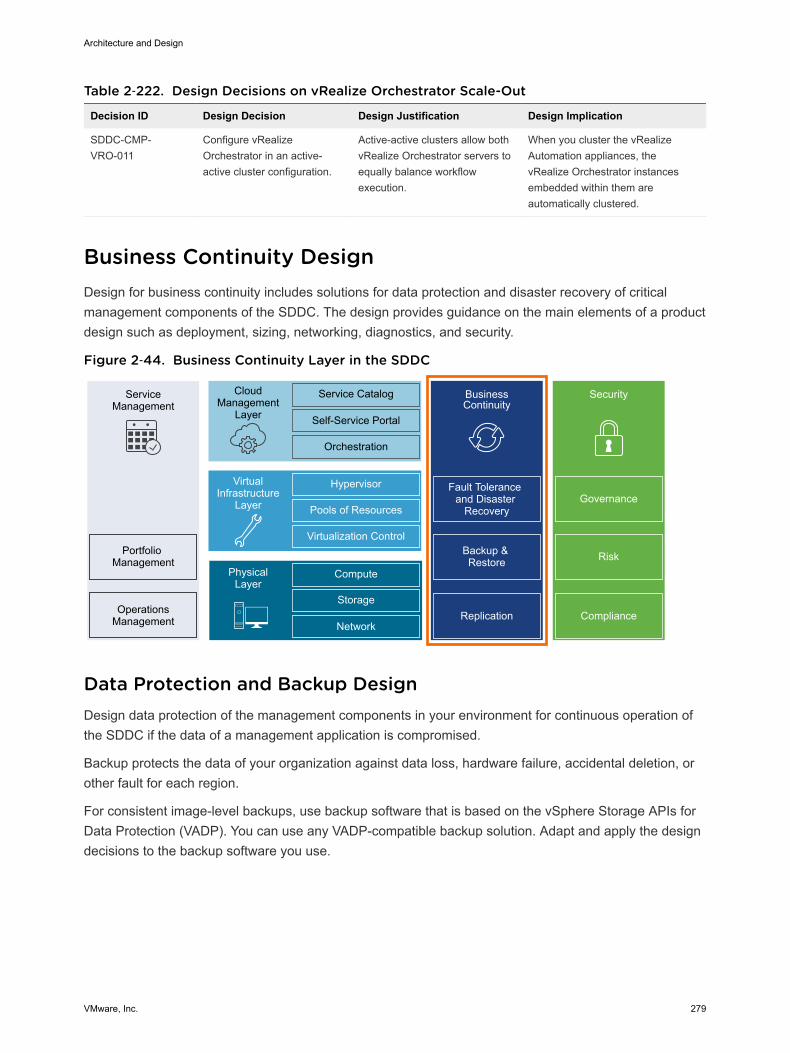
Table 2‑222. Design Decisions on vRealize Orchestrator Scale-Out
Decision ID Design Decision Design Justification Design Implication
SDDC-CMP-VRO-011
Configure vRealizeOrchestrator in an active-active cluster configuration.
Active-active clusters allow bothvRealize Orchestrator servers toequally balance workflowexecution.
When you cluster the vRealizeAutomation appliances, thevRealize Orchestrator instancesembedded within them areautomatically clustered.
Business Continuity Design Design for business continuity includes solutions for data protection and disaster recovery of criticalmanagement components of the SDDC. The design provides guidance on the main elements of a productdesign such as deployment, sizing, networking, diagnostics, and security.
Figure 2‑44. Business Continuity Layer in the SDDC
ServiceManagement
Portfolio Management
OperationsManagement
CloudManagement
Layer
Service Catalog
Self-Service Portal
Orchestration
BusinessContinuity
Fault Tolerance and Disaster
Recovery
Backup & Restore
Hypervisor
Pools of Resources
Virtualization Control
VirtualInfrastructure
Layer
Compute
Storage
Network
PhysicalLayer
Security
Replication Compliance
Risk
Governance
Data Protection and Backup Design Design data protection of the management components in your environment for continuous operation ofthe SDDC if the data of a management application is compromised.
Backup protects the data of your organization against data loss, hardware failure, accidental deletion, orother fault for each region.
For consistent image-level backups, use backup software that is based on the vSphere Storage APIs forData Protection (VADP). You can use any VADP-compatible backup solution. Adapt and apply the designdecisions to the backup software you use.
Architecture and Design
VMware, Inc. 279
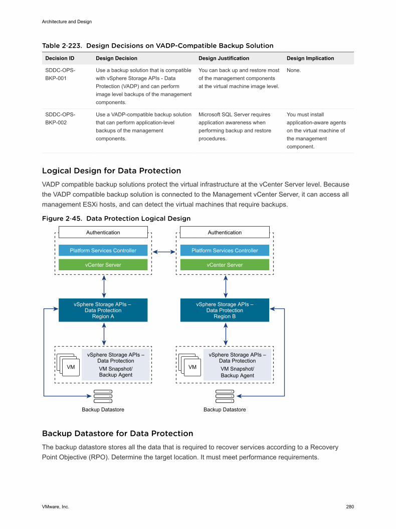
Table 2‑223. Design Decisions on VADP-Compatible Backup Solution
Decision ID Design Decision Design Justification Design Implication
SDDC-OPS-BKP-001
Use a backup solution that is compatiblewith vSphere Storage APIs - DataProtection (VADP) and can performimage level backups of the managementcomponents.
You can back up and restore mostof the management componentsat the virtual machine image level.
None.
SDDC-OPS-BKP-002
Use a VADP-compatible backup solutionthat can perform application-levelbackups of the managementcomponents.
Microsoft SQL Server requiresapplication awareness whenperforming backup and restoreprocedures.
You must installapplication-aware agentson the virtual machine ofthe managementcomponent.
Logical Design for Data Protection VADP compatible backup solutions protect the virtual infrastructure at the vCenter Server level. Becausethe VADP compatible backup solution is connected to the Management vCenter Server, it can access allmanagement ESXi hosts, and can detect the virtual machines that require backups.
Figure 2‑45. Data Protection Logical Design
VM VM
Authentication
Platform Services Controller
vCenter Server
vSphere Storage APIs – Data Protection
Region A
vSphere Storage APIs –Data ProtectionVM Snapshot/Backup Agent
Backup Datastore
Authentication
Platform Services Controller
vCenter Server
vSphere Storage APIs –Data Protection
Region B
vSphere Storage APIs –Data ProtectionVM Snapshot/Backup Agent
Backup Datastore
Backup Datastore for Data Protection The backup datastore stores all the data that is required to recover services according to a RecoveryPoint Objective (RPO). Determine the target location. It must meet performance requirements.
Architecture and Design
VMware, Inc. 280

VADP-compatible backup solutions can use deduplication technology to back up virtual environments atthe data-block level for efficient disk utilization. To optimize backups and use the VMware vSphereStorage APIs, all ESXi hosts must have access to the production storage.
To back up the management components of the SDDC, size your secondary storage appropriately. Youmust provide 6 TB capacity without considering deduplication capabilities.
Table 2‑224. Design Decisions on the Backup Datastore
Decision ID Design Decision Design Justification Design Implication
SDDC-OPS-BKP-003
Allocate a dedicateddatastore for the VADP-compatible backup solutionand the backup dataaccording to NFS PhysicalDesign.
n Emergency restore operations are possibleeven when the primary VMware vSANdatastore is not available because the VADP-compatible backup solution storage volume isseparate from the primary vSAN datastore.
n The amount of storage required for backups isgreater than the amount of storage availablein the vSAN datastore.
You must provideadditional capacity using astorage array.
SDDC-OPS-BKP-004
Provide secondary storagewith a capacity of 6 TB on-disk.
Secondary storage handles the backup of themanagement stack of a single region. Themanagement stack consumes approximately 6 TBof disk space, uncompressed and withoutdeduplication.
You must provide moresecondary storagecapacity to accommodateincreased diskrequirements.
Backup Policies for Data Protection Backup policies specify virtual machine backup options, the schedule window, and retention policies inthis validated design.
Options for Virtual Machine Backup
VADP provides the following options for a virtual machine backup:
Network Block Device(NBD)
Transfers virtual machine data across the network so that VADP-compatiblesolution can perform the backups.
n The performance of the virtual machine network traffic might be lower.
n NBD takes a quiesced snapshot. As a result, it might interrupt the I/Ooperations of the virtual machine to swap the .vmdk file or consolidatethe data after the backup is complete.
n The time to complete the virtual machine backup might be longer thanthe backup window.
n NBD does not work in multi-writer disk mode.
Protection Agent InsideGuest OS
Provides backup of certain applications that are running in the guestoperating system by using an installed backup agent.
n Enables application-consistent backup and recovery with MicrosoftSQL Server, Microsoft SharePoint, and Microsoft Exchange support.
Architecture and Design
VMware, Inc. 281
n Provides more granularity and flexibility to restore on the file level.
Table 2‑225. Design Decisions on Virtual Machine Transport Mode
Decision ID Design Decision Design Justification Design Implication
SDDC-OPS-BKP-005
Use HotAdd to back upvirtual machines.
HotAdd optimizes and speeds upvirtual machine backups, and doesnot impact the vSphere managementnetwork.
All ESXi hosts must have thesame visibility of the virtualmachine datastores.
SDDC-OPS-BKP-006
Use the VADP solution agentfor backups of the MicrosoftSQL Server.
You can restore application datainstead of entire virtual machines.
You must install and maintain theVADP solution agent.
Schedule Window
Even though VADP uses the Changed Block Tracking technology to optimize the backup data, to avoidany business impact, do not use a backup window when the production storage is in high demand.
Table 2‑226. Design Decisions on Backup Schedule
Decision ID Design Decision Design Justification Design Implication
SDDC-OPS-BKP-007
Schedule dailybackups.
You can recover virtual machine data thatis at most a day old.
You lose data that changed sincethe last backup 24 hours ago.
SDDC-OPS-BKP-008
Schedule backupsoutside the productionpeak times.
Backups occur when the system is underthe lowest load. Make sure that backupsare completed in the shortest time possiblewith the smallest risk of errors.
There may be limited non-peak timeto complete backups. Backupduration will be impacte dy storageI/O throughput.
Retention Policies
Retention policies are properties of a backup job. If you group virtual machines by business priority, youcan set the retention requirements according to the business priority.
Table 2‑227. Design Decisions on Backup Retention Policies
Decision ID Design Decision Design Justification Design Implication
SDDC-OPS-BKP-009
Retain backups for atleast 3 days.
Keeping 3 days of backups enablesadministrators to restore the managementapplications to a state within the last 72hours.
Depending on the rate of change invirtual machines, backup retentionpolicy can increase the storage targetsize.
SDDC-OPS-BKP-010
Retain backups forcross-regionreplicated backup jobsfor at least 1 day.
Keeping 1 day of a backup for replicatedjobs enables administrators, in the event ofa disaster recovery situation in whichfailover was unsuccessful, to restore theirregion-independent applications to a statewithin the last 24 hours.
You lost data that has changed sincethe last backup 24 hours ago. Thisdata loss also increases the storagerequirements for the backup solutionin a multi-region configuration.
Architecture and Design
VMware, Inc. 282
Information Security and Access Control for Data Protection You use a service account for authentication and authorization of a VADP-compatible backup solution forbackup and restore operations.
Table 2‑228. Design Decisions on Authorization and Authentication Management for aVADP-Compatible Solution
Decision ID Design Decision Design Justification Design Implication
SDDC-OPS-BKP-011
Configure a service accountsvc-bck-vcenter in vCenterServer for application-to-application communicationfrom VADP-compatible backupsolution with vSphere.
Provides the following access control features:n Provide the VADP- compatible backup
solution with a minimum set of permissionsthat are required to perform backup andrestore operations.
n In the event of a compromised account, theaccessibility in the destination applicationremains restricted.
n You can introduce improved accountabilityin tracking request-response interactionsbetween the components of the SDDC.
You must maintain theservice account's lifecycle outside of theSDDC stack to ensure itsavailability.
SDDC-OPS-BKP-012
Use global permissions whenyou create the svc-bck-vcenterservice account in vCenterServer.
n Simplifies and standardizes the deploymentof the service account across all vCenterServer instances in the same vSpheredomain.
n Provides a consistent authorization layer.
All vCenter Serverinstances must be in thesame vSphere domain.
Component Backup Jobs for Data Protection You can configure backup for each SDDC management component separately. This design does notsuggest a requirement to back up the entire SDDC.
Some products can perform internal configuration backups. Use those products in addition to the wholeVM component backups as appropriate.
Table 2‑229. Design Decision on Component Backup Jobs
Decision ID Design Decision Design Justification Design Implication
SDDC-OPS-BKP-013
Use the internalconfiguration backup of NSXfor vSphere.
Restoring small configuration filescan be a faster and less damagingmethod to achieve a similarrestoration of functionality.
You must provide space on anSFT or FTP server to store theNSX configuration backups.
Site Recovery Manager and vSphere Replication DesignTo support disaster recovery (DR) in the SDDC, you protect vRealize Operations Manager, vRealizeAutomation, vRealize Business for Cloud, and vRealize Suite Lifecycle Manager by using Site RecoveryManager and vSphere Replication. When failing over to a recovery region, these managementapplications continue the support of operations management and cloud management platformfunctionality.
Architecture and Design
VMware, Inc. 283
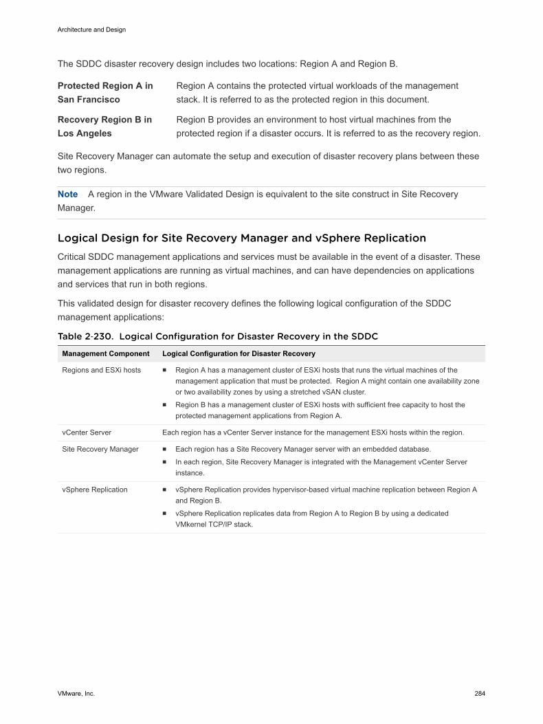
The SDDC disaster recovery design includes two locations: Region A and Region B.
Protected Region A inSan Francisco
Region A contains the protected virtual workloads of the managementstack. It is referred to as the protected region in this document.
Recovery Region B inLos Angeles
Region B provides an environment to host virtual machines from theprotected region if a disaster occurs. It is referred to as the recovery region.
Site Recovery Manager can automate the setup and execution of disaster recovery plans between thesetwo regions.
Note A region in the VMware Validated Design is equivalent to the site construct in Site RecoveryManager.
Logical Design for Site Recovery Manager and vSphere ReplicationCritical SDDC management applications and services must be available in the event of a disaster. Thesemanagement applications are running as virtual machines, and can have dependencies on applicationsand services that run in both regions.
This validated design for disaster recovery defines the following logical configuration of the SDDCmanagement applications:
Table 2‑230. Logical Configuration for Disaster Recovery in the SDDC
Management Component Logical Configuration for Disaster Recovery
Regions and ESXi hosts n Region A has a management cluster of ESXi hosts that runs the virtual machines of themanagement application that must be protected. Region A might contain one availability zoneor two availability zones by using a stretched vSAN cluster.
n Region B has a management cluster of ESXi hosts with sufficient free capacity to host theprotected management applications from Region A.
vCenter Server Each region has a vCenter Server instance for the management ESXi hosts within the region.
Site Recovery Manager n Each region has a Site Recovery Manager server with an embedded database. n In each region, Site Recovery Manager is integrated with the Management vCenter Server
instance.
vSphere Replication n vSphere Replication provides hypervisor-based virtual machine replication between Region Aand Region B.
n vSphere Replication replicates data from Region A to Region B by using a dedicatedVMkernel TCP/IP stack.
Architecture and Design
VMware, Inc. 284
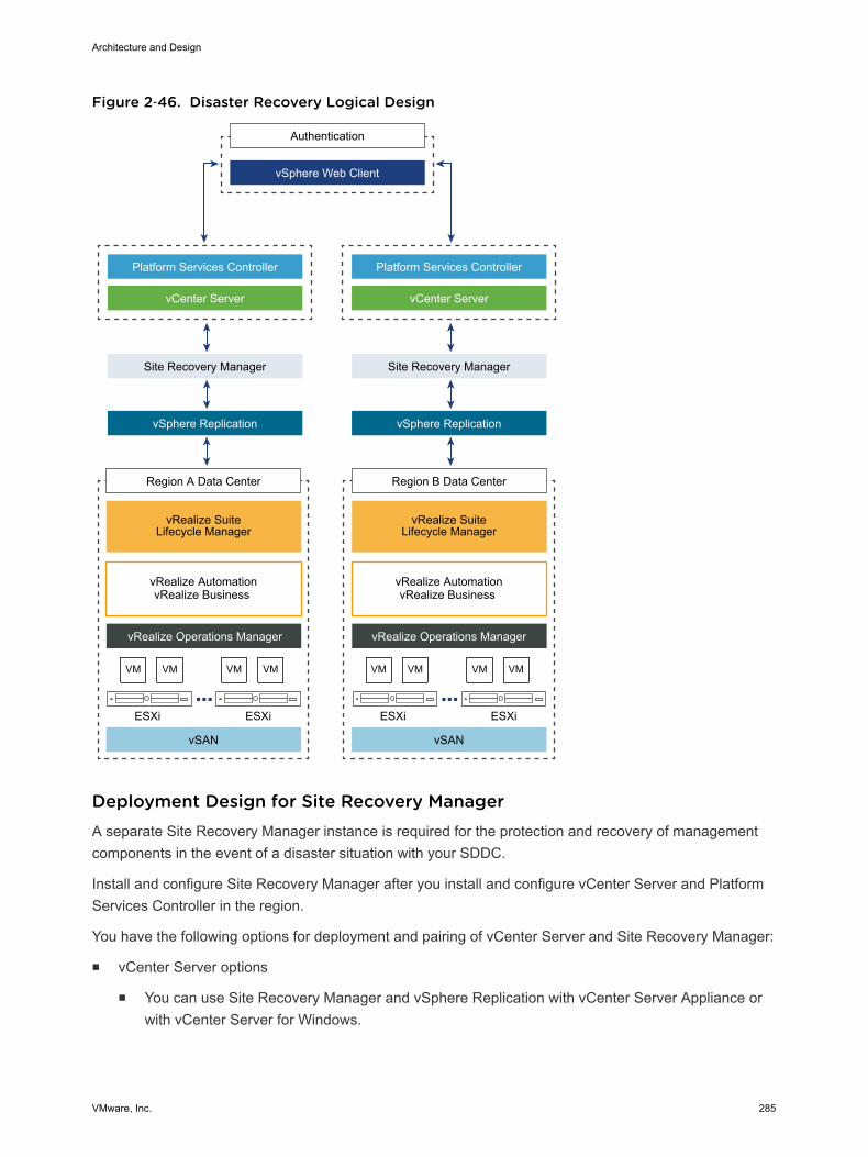
Figure 2‑46. Disaster Recovery Logical Design
VM VM VM VM VM VM VM VM
Authentication
Platform Services Controller
vCenter Server
vSphere Web Client
Site Recovery Manager
vSphere Replication
Region A Data Center
vSAN
vRealize AutomationvRealize Business
Platform Services Controller
vCenter Server
Site Recovery Manager
vSphere Replication
vRealize Operations Manager vRealize Operations Manager
ESXi ESXi
Region B Data Center
vRealize Suite Lifecycle Manager
vRealize Suite Lifecycle Manager
vSAN
vRealize AutomationvRealize Business
ESXi ESXi
Deployment Design for Site Recovery ManagerA separate Site Recovery Manager instance is required for the protection and recovery of managementcomponents in the event of a disaster situation with your SDDC.
Install and configure Site Recovery Manager after you install and configure vCenter Server and PlatformServices Controller in the region.
You have the following options for deployment and pairing of vCenter Server and Site Recovery Manager:
n vCenter Server options
n You can use Site Recovery Manager and vSphere Replication with vCenter Server Appliance orwith vCenter Server for Windows.
Architecture and Design
VMware, Inc. 285
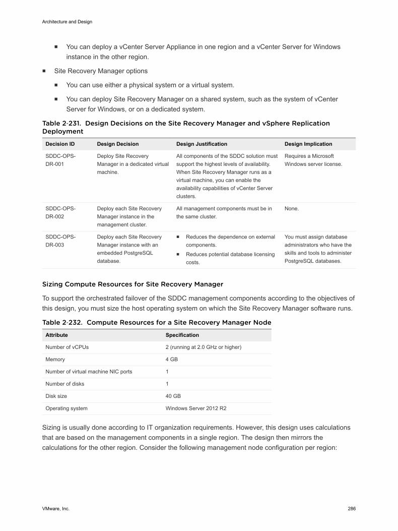
n You can deploy a vCenter Server Appliance in one region and a vCenter Server for Windowsinstance in the other region.
n Site Recovery Manager options
n You can use either a physical system or a virtual system.
n You can deploy Site Recovery Manager on a shared system, such as the system of vCenterServer for Windows, or on a dedicated system.
Table 2‑231. Design Decisions on the Site Recovery Manager and vSphere ReplicationDeployment
Decision ID Design Decision Design Justification Design Implication
SDDC-OPS-DR-001
Deploy Site RecoveryManager in a dedicated virtualmachine.
All components of the SDDC solution mustsupport the highest levels of availability.When Site Recovery Manager runs as avirtual machine, you can enable theavailability capabilities of vCenter Serverclusters.
Requires a MicrosoftWindows server license.
SDDC-OPS-DR-002
Deploy each Site RecoveryManager instance in themanagement cluster.
All management components must be inthe same cluster.
None.
SDDC-OPS-DR-003
Deploy each Site RecoveryManager instance with anembedded PostgreSQLdatabase.
n Reduces the dependence on externalcomponents.
n Reduces potential database licensingcosts.
You must assign databaseadministrators who have theskills and tools to administerPostgreSQL databases.
Sizing Compute Resources for Site Recovery Manager
To support the orchestrated failover of the SDDC management components according to the objectives ofthis design, you must size the host operating system on which the Site Recovery Manager software runs.
Table 2‑232. Compute Resources for a Site Recovery Manager Node
Attribute Specification
Number of vCPUs 2 (running at 2.0 GHz or higher)
Memory 4 GB
Number of virtual machine NIC ports 1
Number of disks 1
Disk size 40 GB
Operating system Windows Server 2012 R2
Sizing is usually done according to IT organization requirements. However, this design uses calculationsthat are based on the management components in a single region. The design then mirrors thecalculations for the other region. Consider the following management node configuration per region:
Architecture and Design
VMware, Inc. 286

Table 2‑233. SDDC Nodes with Failover Support
Management Component Node Type Number of Nodes
Cloud Management Platform vRealize Automation Appliance 3
vRealize IaaS Web Server 2
vRealize IaaS Management Server 2
vRealize IaaS DEM 2
Microsoft SQL Server 1
vRealize Business for Cloud Appliance 1
vRealize Suite Lifecycle Manager vRealize Suite Lifecycle ManagerAppliance
1
vRealize Operations Manager vRealize Operations Manager Master 1
vRealize Operations Manager MasterReplica
1
vRealize Operations Manager Data 1
You must protect a total of 15 virtual machines.
You use vSphere Replication as the replication solution between the Site Recovery Manager sites, andyou distribute the virtual machines in two protection groups.
Table 2‑234. Design Decisions on Compute Resources for the Site Recovery Manager Nodes
Decision ID Design Decision Design Justification Design Implication
SDDC-OPS-DR-004
Deploy Site Recovery Manageron a Microsoft Windows Serverguest OS according to thefollowing specifications:n 2 vCPUsn 4 GB memoryn 40 GB diskn 1 GbE pNIC
Accommodates the protection ofmanagement components to supply thehighest levels of availability. This sizefurther accommodates the followingsetup:n The number of protected
management virtual machines asdefined in Table 2‑233
n Two protection groupsn Two recovery plans
You must increase the sizeof the nodes if you addmore protection groups,virtual machines to protector recovery plans.
Placeholder Virtual Machines
Site Recovery Manager creates a placeholder virtual machine on the recovery region for every machinefrom the Site Recovery Manager protection group. Placeholder virtual machine files are small becausethey contain virtual machine configuration metadata but no virtual machine disks. Site Recovery Manageradds the placeholder virtual machines as recovery region objects to the vCenter Server inventory.
Architecture and Design
VMware, Inc. 287
Networking Design for Site Recovery Manager and vSphere ReplicationMoving an application physically from one region to another represents a networking challenge,especially if applications have hard-coded IP addresses. According to the requirements for the networkaddress space and IP address assignment, you use either the same or a different IP address at therecovery region. In many situations, you assign new IP addresses because VLANs might not stretchbetween regions.
This design uses NSX for vSphere to create virtual networks called application virtual networks (AVNs). InAVNs, you can place workloads using a single IP network address space that spans across data centers.AVNs have the following benefits:
n Single IP network address space providing mobility between data centers
n Simplified disaster recovery procedures
After a failover, the recovered application is available under the same IPv4 address.
Architecture and Design
VMware, Inc. 288
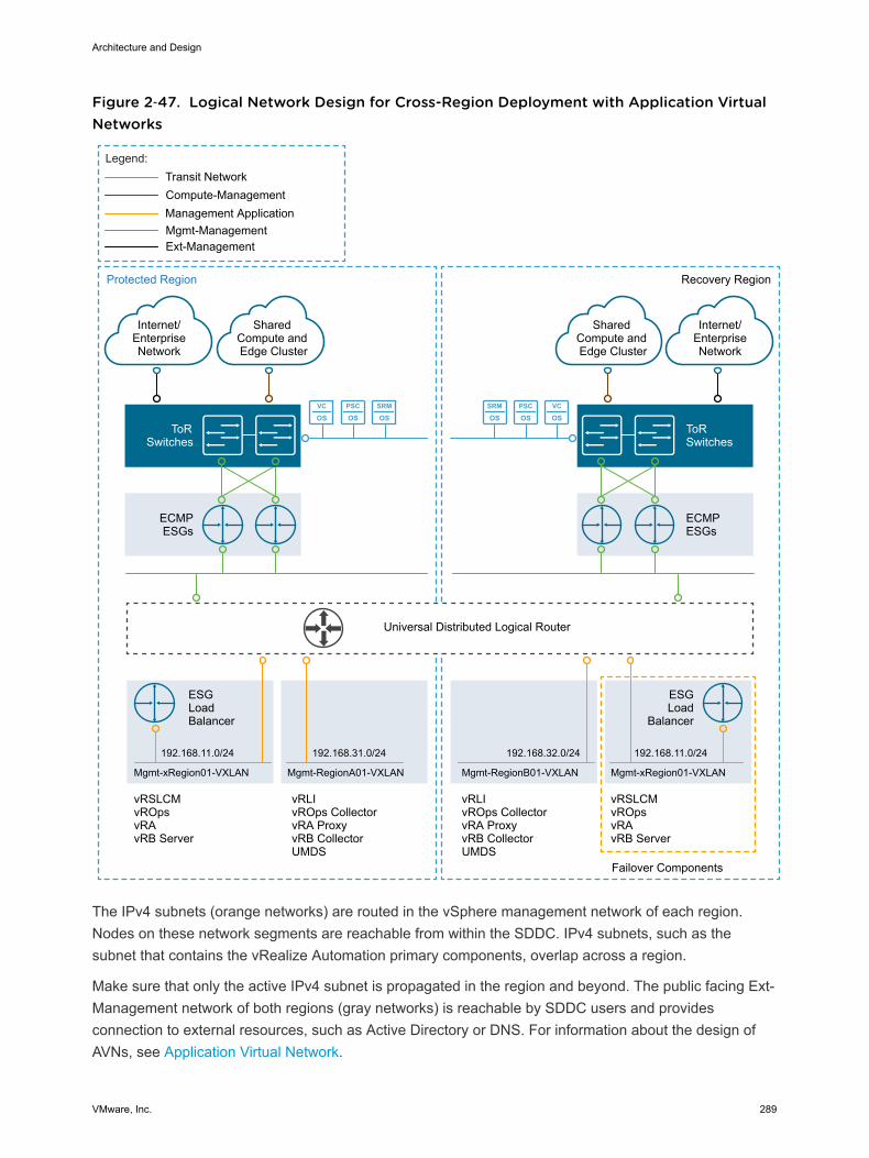
Figure 2‑47. Logical Network Design for Cross-Region Deployment with Application VirtualNetworks
PSC
OSSRM
OSVC
OSPSC
OSSRM
OSVC
OS
Protected Region
ECMPESGs
ToRSwitches
Internet/EnterpriseNetwork
Mgmt-Management
Compute-Management
Legend:
Shared Compute and Edge Cluster
192.168.11.0/24
Transit Network
Management Application
vRLIvROps CollectorvRA ProxyvRB CollectorUMDS
vRSLCMvROpsvRAvRB Server
ESGLoadBalancer
Mgmt-xRegion01-VXLAN
192.168.31.0/24
Mgmt-RegionА01-VXLAN
Universal Distributed Logical Router
Recovery Region
ECMPESGs
ToR Switches
vRLIvROps CollectorvRA ProxyvRB CollectorUMDS
vRSLCMvROpsvRAvRB Server
192.168.32.0/24
Mgmt-RegionB01-VXLAN
192.168.11.0/24
ESGLoad
Balancer
Mgmt-xRegion01-VXLAN
Failover Components
Internet/EnterpriseNetwork
Shared Compute and Edge Cluster
Ext-Management
The IPv4 subnets (orange networks) are routed in the vSphere management network of each region.Nodes on these network segments are reachable from within the SDDC. IPv4 subnets, such as thesubnet that contains the vRealize Automation primary components, overlap across a region.
Make sure that only the active IPv4 subnet is propagated in the region and beyond. The public facing Ext-Management network of both regions (gray networks) is reachable by SDDC users and providesconnection to external resources, such as Active Directory or DNS. For information about the design ofAVNs, see Application Virtual Network.
Architecture and Design
VMware, Inc. 289
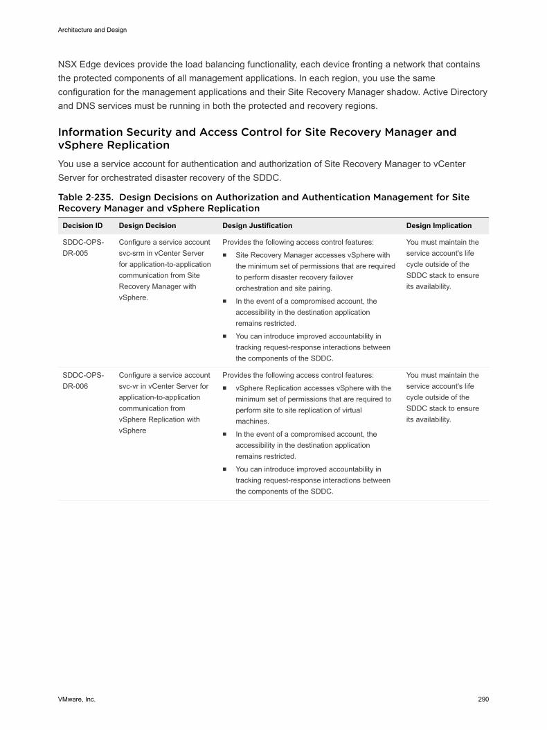
NSX Edge devices provide the load balancing functionality, each device fronting a network that containsthe protected components of all management applications. In each region, you use the sameconfiguration for the management applications and their Site Recovery Manager shadow. Active Directoryand DNS services must be running in both the protected and recovery regions.
Information Security and Access Control for Site Recovery Manager andvSphere ReplicationYou use a service account for authentication and authorization of Site Recovery Manager to vCenterServer for orchestrated disaster recovery of the SDDC.
Table 2‑235. Design Decisions on Authorization and Authentication Management for SiteRecovery Manager and vSphere Replication
Decision ID Design Decision Design Justification Design Implication
SDDC-OPS-DR-005
Configure a service accountsvc-srm in vCenter Serverfor application-to-applicationcommunication from SiteRecovery Manager withvSphere.
Provides the following access control features:n Site Recovery Manager accesses vSphere with
the minimum set of permissions that are requiredto perform disaster recovery failoverorchestration and site pairing.
n In the event of a compromised account, theaccessibility in the destination applicationremains restricted.
n You can introduce improved accountability intracking request-response interactions betweenthe components of the SDDC.
You must maintain theservice account's lifecycle outside of theSDDC stack to ensureits availability.
SDDC-OPS-DR-006
Configure a service accountsvc-vr in vCenter Server forapplication-to-applicationcommunication fromvSphere Replication withvSphere
Provides the following access control features:n vSphere Replication accesses vSphere with the
minimum set of permissions that are required toperform site to site replication of virtualmachines.
n In the event of a compromised account, theaccessibility in the destination applicationremains restricted.
n You can introduce improved accountability intracking request-response interactions betweenthe components of the SDDC.
You must maintain theservice account's lifecycle outside of theSDDC stack to ensureits availability.
Architecture and Design
VMware, Inc. 290
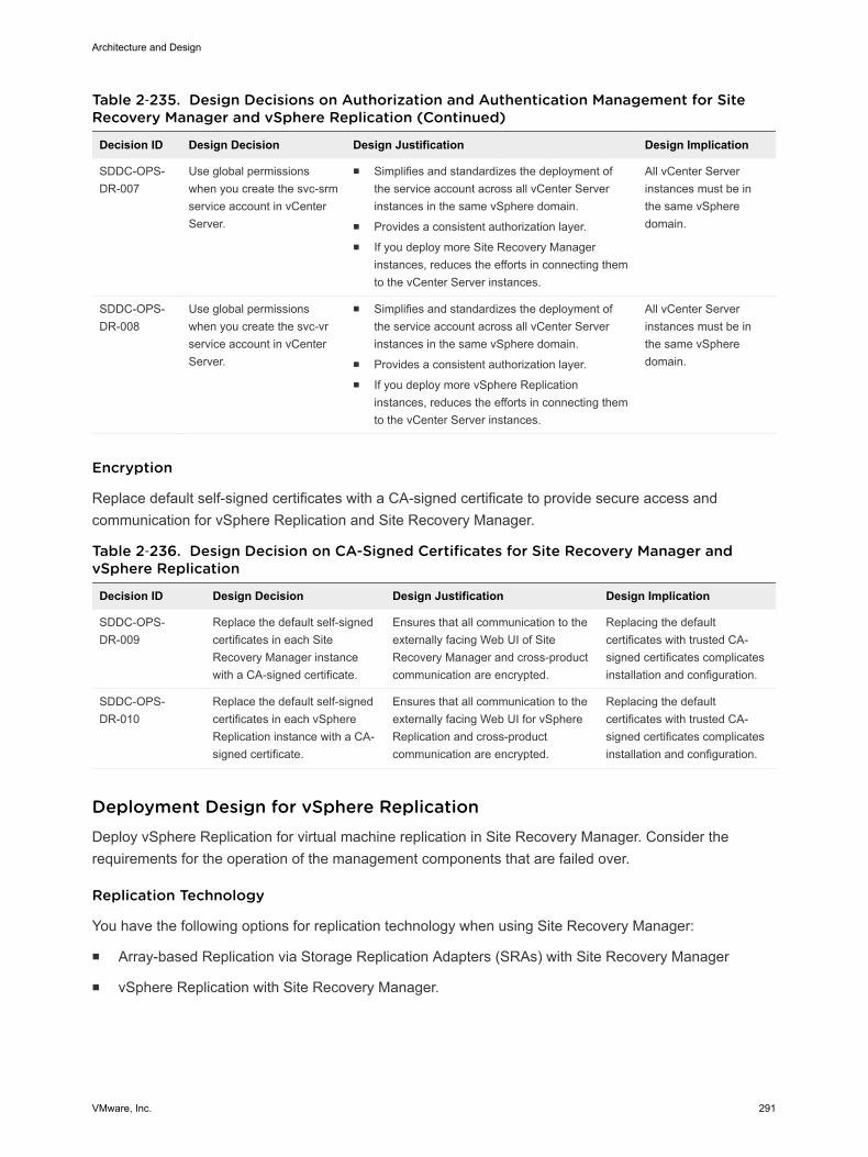
Table 2‑235. Design Decisions on Authorization and Authentication Management for SiteRecovery Manager and vSphere Replication (Continued)
Decision ID Design Decision Design Justification Design Implication
SDDC-OPS-DR-007
Use global permissionswhen you create the svc-srmservice account in vCenterServer.
n Simplifies and standardizes the deployment ofthe service account across all vCenter Serverinstances in the same vSphere domain.
n Provides a consistent authorization layer.n If you deploy more Site Recovery Manager
instances, reduces the efforts in connecting themto the vCenter Server instances.
All vCenter Serverinstances must be inthe same vSpheredomain.
SDDC-OPS-DR-008
Use global permissionswhen you create the svc-vrservice account in vCenterServer.
n Simplifies and standardizes the deployment ofthe service account across all vCenter Serverinstances in the same vSphere domain.
n Provides a consistent authorization layer.n If you deploy more vSphere Replication
instances, reduces the efforts in connecting themto the vCenter Server instances.
All vCenter Serverinstances must be inthe same vSpheredomain.
Encryption
Replace default self-signed certificates with a CA-signed certificate to provide secure access andcommunication for vSphere Replication and Site Recovery Manager.
Table 2‑236. Design Decision on CA-Signed Certificates for Site Recovery Manager andvSphere Replication
Decision ID Design Decision Design Justification Design Implication
SDDC-OPS-DR-009
Replace the default self-signedcertificates in each SiteRecovery Manager instancewith a CA-signed certificate.
Ensures that all communication to theexternally facing Web UI of SiteRecovery Manager and cross-productcommunication are encrypted.
Replacing the defaultcertificates with trusted CA-signed certificates complicatesinstallation and configuration.
SDDC-OPS-DR-010
Replace the default self-signedcertificates in each vSphereReplication instance with a CA-signed certificate.
Ensures that all communication to theexternally facing Web UI for vSphereReplication and cross-productcommunication are encrypted.
Replacing the defaultcertificates with trusted CA-signed certificates complicatesinstallation and configuration.
Deployment Design for vSphere ReplicationDeploy vSphere Replication for virtual machine replication in Site Recovery Manager. Consider therequirements for the operation of the management components that are failed over.
Replication Technology
You have the following options for replication technology when using Site Recovery Manager:
n Array-based Replication via Storage Replication Adapters (SRAs) with Site Recovery Manager
n vSphere Replication with Site Recovery Manager.
Architecture and Design
VMware, Inc. 291
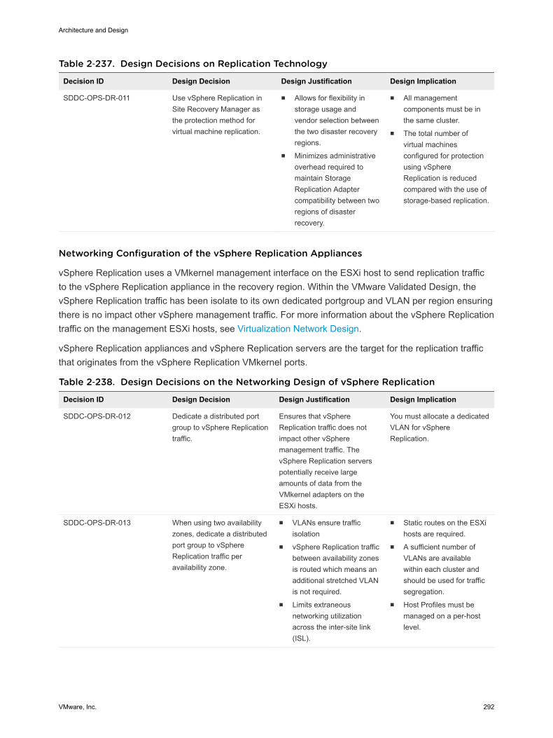
Table 2‑237. Design Decisions on Replication Technology
Decision ID Design Decision Design Justification Design Implication
SDDC-OPS-DR-011 Use vSphere Replication inSite Recovery Manager asthe protection method forvirtual machine replication.
n Allows for flexibility instorage usage andvendor selection betweenthe two disaster recoveryregions.
n Minimizes administrativeoverhead required tomaintain StorageReplication Adaptercompatibility between tworegions of disasterrecovery.
n All managementcomponents must be inthe same cluster.
n The total number ofvirtual machinesconfigured for protectionusing vSphereReplication is reducedcompared with the use ofstorage-based replication.
Networking Configuration of the vSphere Replication Appliances
vSphere Replication uses a VMkernel management interface on the ESXi host to send replication trafficto the vSphere Replication appliance in the recovery region. Within the VMware Validated Design, thevSphere Replication traffic has been isolate to its own dedicated portgroup and VLAN per region ensuringthere is no impact other vSphere management traffic. For more information about the vSphere Replicationtraffic on the management ESXi hosts, see Virtualization Network Design.
vSphere Replication appliances and vSphere Replication servers are the target for the replication trafficthat originates from the vSphere Replication VMkernel ports.
Table 2‑238. Design Decisions on the Networking Design of vSphere Replication
Decision ID Design Decision Design Justification Design Implication
SDDC-OPS-DR-012 Dedicate a distributed portgroup to vSphere Replicationtraffic.
Ensures that vSphereReplication traffic does notimpact other vSpheremanagement traffic. ThevSphere Replication serverspotentially receive largeamounts of data from theVMkernel adapters on theESXi hosts.
You must allocate a dedicatedVLAN for vSphereReplication.
SDDC-OPS-DR-013 When using two availabilityzones, dedicate a distributedport group to vSphereReplication traffic peravailability zone.
n VLANs ensure trafficisolation
n vSphere Replication trafficbetween availability zonesis routed which means anadditional stretched VLANis not required.
n Limits extraneousnetworking utilizationacross the inter-site link(ISL).
n Static routes on the ESXihosts are required.
n A sufficient number ofVLANs are availablewithin each cluster andshould be used for trafficsegregation.
n Host Profiles must bemanaged on a per-hostlevel.
Architecture and Design
VMware, Inc. 292
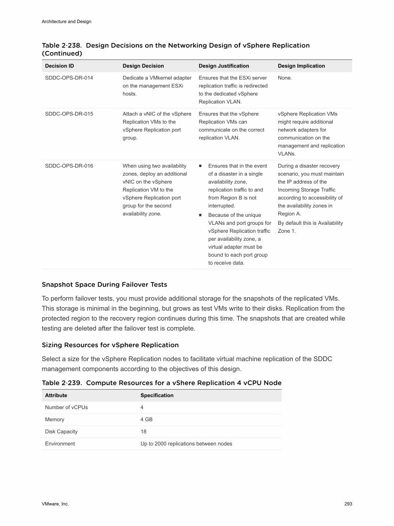
Table 2‑238. Design Decisions on the Networking Design of vSphere Replication(Continued)
Decision ID Design Decision Design Justification Design Implication
SDDC-OPS-DR-014 Dedicate a VMkernel adapteron the management ESXihosts.
Ensures that the ESXi serverreplication traffic is redirectedto the dedicated vSphereReplication VLAN.
None.
SDDC-OPS-DR-015 Attach a vNIC of the vSphereReplication VMs to thevSphere Replication portgroup.
Ensures that the vSphereReplication VMs cancommunicate on the correctreplication VLAN.
vSphere Replication VMsmight require additionalnetwork adapters forcommunication on themanagement and replicationVLANs.
SDDC-OPS-DR-016 When using two availabilityzones, deploy an additionalvNIC on the vSphereReplication VM to thevSphere Replication portgroup for the secondavailability zone.
n Ensures that in the eventof a disaster in a singleavailability zone,replication traffic to andfrom Region B is notinterrupted.
n Because of the uniqueVLANs and port groups forvSphere Replication trafficper availability zone, avirtual adapter must bebound to each port groupto receive data.
During a disaster recoveryscenario, you must maintainthe IP address of theIncoming Storage Trafficaccording to accessibility ofthe availability zones inRegion A.
By default this is AvailabilityZone 1.
Snapshot Space During Failover Tests
To perform failover tests, you must provide additional storage for the snapshots of the replicated VMs.This storage is minimal in the beginning, but grows as test VMs write to their disks. Replication from theprotected region to the recovery region continues during this time. The snapshots that are created whiletesting are deleted after the failover test is complete.
Sizing Resources for vSphere Replication
Select a size for the vSphere Replication nodes to facilitate virtual machine replication of the SDDCmanagement components according to the objectives of this design.
Table 2‑239. Compute Resources for a vShere Replication 4 vCPU Node
Attribute Specification
Number of vCPUs 4
Memory 4 GB
Disk Capacity 18
Environment Up to 2000 replications between nodes
Architecture and Design
VMware, Inc. 293
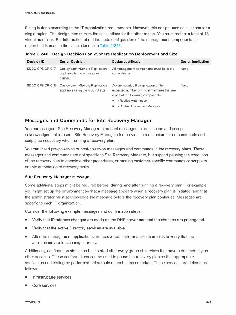
Sizing is done according to the IT organization requirements. However, this design uses calculations for asingle region. The design then mirrors the calculations for the other region. You must protect a total of 13virtual machines. For information about the node configuration of the management components perregion that is used in the calculations, see Table 2‑233.
Table 2‑240. Design Decisions on vSphere Replication Deployment and Size
Decision ID Design Decision Design Justification Design Implication
SDDC-OPS-DR-017 Deploy each vSphere Replicationappliance in the managementcluster.
All management components must be in thesame cluster.
None
SDDC-OPS-DR-018 Deploy each vSphere Replicationappliance using the 4 vCPU size.
Accommodates the replication of theexpected number of virtual machines that area part of the following components:n vRealize Automationn vRealize Operations Manager
None.
Messages and Commands for Site Recovery ManagerYou can configure Site Recovery Manager to present messages for notification and acceptacknowledgement to users. Site Recovery Manager also provides a mechanism to run commands andscripts as necessary when running a recovery plan.
You can insert pre-power-on or post-power-on messages and commands in the recovery plans. Thesemessages and commands are not specific to Site Recovery Manager, but support pausing the executionof the recovery plan to complete other procedures, or running customer-specific commands or scripts toenable automation of recovery tasks.
Site Recovery Manager Messages
Some additional steps might be required before, during, and after running a recovery plan. For example,you might set up the environment so that a message appears when a recovery plan is initiated, and thatthe administrator must acknowledge the message before the recovery plan continues. Messages arespecific to each IT organization.
Consider the following example messages and confirmation steps:
n Verify that IP address changes are made on the DNS server and that the changes are propagated.
n Verify that the Active Directory services are available.
n After the management applications are recovered, perform application tests to verify that theapplications are functioning correctly.
Additionally, confirmation steps can be inserted after every group of services that have a dependency onother services. These conformations can be used to pause the recovery plan so that appropriateverification and testing be performed before subsequent steps are taken. These services are defined asfollows:
n Infrastructure services
n Core services
Architecture and Design
VMware, Inc. 294
n Database services
n Middleware services
n Application services
n Web services
Details on each message are specified in the workflow definition of the individual recovery plan.
Site Recovery Manager Commands
You can run custom scripts to perform infrastructure configuration updates or configuration changes onthe environment of a virtual machine. The scripts that a recovery plan runs are located on the SiteRecovery Manager server. The scripts can run against the Site Recovery Manager server or can impact avirtual machine.
If a script must run on the virtual machine, Site Recovery Manager does not run it directly, but instructsthe virtual machine to do it. The audit trail that Site Recovery Manager provides does not record theexecution of the script because the operation is on the target virtual machine.
Scripts or commands must be available in the path on the virtual machine according to the followingguidelines:
n Use full paths to all executables. For example c:\windows\system32\cmd.exe instead of cmd.exe.
n Call only.exe or .com files from the scripts. Command-line scripts can call only executables.
n To run a batch file, start the shell command with c:\windows\system32\cmd.exe.
The scripts that are run after powering on a virtual machine are executed under the Windows ServersLocal Security Authority of the Site Recovery Manager server. Store post-power-on scripts on the SiteRecovery Manager virtual machine. Do not store such scripts on a remote network share.
Recovery Plan for Site Recovery Manager and vSphere ReplicationA recovery plan is the automated plan (runbook) for full or partial failover from Region A to Region B.
Recovery Time Objective
The recovery time objective (RTO) is the targeted duration of time and a service level in which a businessprocess must be restored as a result of an IT service or data loss issue, such as a natural disaster.
Architecture and Design
VMware, Inc. 295
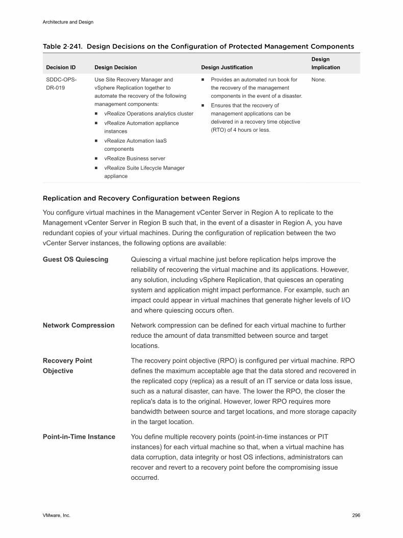
Table 2‑241. Design Decisions on the Configuration of Protected Management Components
Decision ID Design Decision Design JustificationDesignImplication
SDDC-OPS-DR-019
Use Site Recovery Manager andvSphere Replication together toautomate the recovery of the followingmanagement components:n vRealize Operations analytics clustern vRealize Automation appliance
instancesn vRealize Automation IaaS
componentsn vRealize Business servern vRealize Suite Lifecycle Manager
appliance
n Provides an automated run book forthe recovery of the managementcomponents in the event of a disaster.
n Ensures that the recovery ofmanagement applications can bedelivered in a recovery time objective(RTO) of 4 hours or less.
None.
Replication and Recovery Configuration between Regions
You configure virtual machines in the Management vCenter Server in Region A to replicate to theManagement vCenter Server in Region B such that, in the event of a disaster in Region A, you haveredundant copies of your virtual machines. During the configuration of replication between the twovCenter Server instances, the following options are available:
Guest OS Quiescing Quiescing a virtual machine just before replication helps improve thereliability of recovering the virtual machine and its applications. However,any solution, including vSphere Replication, that quiesces an operatingsystem and application might impact performance. For example, such animpact could appear in virtual machines that generate higher levels of I/Oand where quiescing occurs often.
Network Compression Network compression can be defined for each virtual machine to furtherreduce the amount of data transmitted between source and targetlocations.
Recovery PointObjective
The recovery point objective (RPO) is configured per virtual machine. RPOdefines the maximum acceptable age that the data stored and recovered inthe replicated copy (replica) as a result of an IT service or data loss issue,such as a natural disaster, can have. The lower the RPO, the closer thereplica's data is to the original. However, lower RPO requires morebandwidth between source and target locations, and more storage capacityin the target location.
Point-in-Time Instance You define multiple recovery points (point-in-time instances or PITinstances) for each virtual machine so that, when a virtual machine hasdata corruption, data integrity or host OS infections, administrators canrecover and revert to a recovery point before the compromising issueoccurred.
Architecture and Design
VMware, Inc. 296

Table 2‑242. Design Decisions on the vSphere Replication Configuration
Decision ID Design Decision Design Justification Design Implication
SDDC-OPS-DR-020
Do not enable guest OSquiescing in the policies forthe management virtualmachines in vSphereReplication.
Not all management virtual machinessupport the use of guest OS quiescing.Using the quiescing operation mightresult in an outage.
The replicas of the managementvirtual machines that are stored inthe target region are crash-consistent rather than application-consistent.
SDDC-OPS-DR-021
Enable network compressionon the management virtualmachine policies in vSphereReplication.
n Ensures the vSphere Replicationtraffic over the network has areduced footprint.
n Reduces the amount of buffermemory used on the vSphereReplication VMs.
To perform compression anddecompression of data, vSphereReplication VM might requiremore CPU resources on thesource site as more virtualmachines are protected.
SDDC-OPS-DR-022
Enable a recovery pointobjective (RPO) of 15 minuteson the management virtualmachine policies in vSphereReplication.
n Ensures that the managementapplication that is failing over after adisaster recovery event contains alldata except any changes prior to 15minutes of the event.
n Achieves the availability andrecovery target of 99% of thisVMware Validated Design.
Any changes that are made up to15 minutes before a disasterrecovery event are lost.
SDDC-OPS-DR-023
Enable point-in-time (PIT)instances, keeping 3 copiesover a 24-hour period on themanagement virtual machinepolicies in vSphereReplication.
Ensures application integrity for themanagement application that is failingover after a disaster recovery eventoccurs.
Increasing the number of retainedrecovery point instancesincreases the disk usage on thevSAN datastore.
Startup Order and Response Time
Virtual machine priority determines virtual machine startup order.
n All priority 1 virtual machines are started before priority 2 virtual machines.
n All priority 2 virtual machines are started before priority 3 virtual machines.
n All priority 3 virtual machines are started before priority 4 virtual machines.
n All priority 4 virtual machines are started before priority 5 virtual machines.
n You can additionally set startup order of virtual machines within each priority group.
You can configure the following timeout parameters:
n Response time, which defines the time to wait after the first virtual machine powers on beforeproceeding to the next virtual machine in the plan.
n Maximum time to wait if the virtual machine fails to power on before proceeding to the next virtualmachine.
You can adjust response time values as necessary during execution of the recovery plan test todetermine the appropriate response time values.
Architecture and Design
VMware, Inc. 297
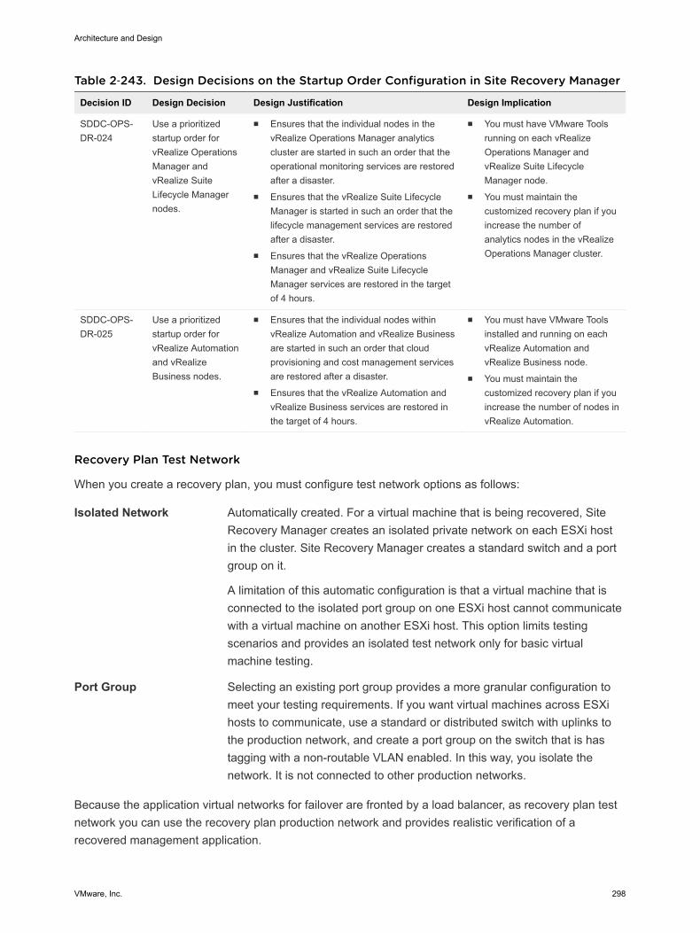
Table 2‑243. Design Decisions on the Startup Order Configuration in Site Recovery Manager
Decision ID Design Decision Design Justification Design Implication
SDDC-OPS-DR-024
Use a prioritizedstartup order forvRealize OperationsManager andvRealize SuiteLifecycle Managernodes.
n Ensures that the individual nodes in thevRealize Operations Manager analyticscluster are started in such an order that theoperational monitoring services are restoredafter a disaster.
n Ensures that the vRealize Suite LifecycleManager is started in such an order that thelifecycle management services are restoredafter a disaster.
n Ensures that the vRealize OperationsManager and vRealize Suite LifecycleManager services are restored in the targetof 4 hours.
n You must have VMware Toolsrunning on each vRealizeOperations Manager andvRealize Suite LifecycleManager node.
n You must maintain thecustomized recovery plan if youincrease the number ofanalytics nodes in the vRealizeOperations Manager cluster.
SDDC-OPS-DR-025
Use a prioritizedstartup order forvRealize Automationand vRealizeBusiness nodes.
n Ensures that the individual nodes withinvRealize Automation and vRealize Businessare started in such an order that cloudprovisioning and cost management servicesare restored after a disaster.
n Ensures that the vRealize Automation andvRealize Business services are restored inthe target of 4 hours.
n You must have VMware Toolsinstalled and running on eachvRealize Automation andvRealize Business node.
n You must maintain thecustomized recovery plan if youincrease the number of nodes invRealize Automation.
Recovery Plan Test Network
When you create a recovery plan, you must configure test network options as follows:
Isolated Network Automatically created. For a virtual machine that is being recovered, SiteRecovery Manager creates an isolated private network on each ESXi hostin the cluster. Site Recovery Manager creates a standard switch and a portgroup on it.
A limitation of this automatic configuration is that a virtual machine that isconnected to the isolated port group on one ESXi host cannot communicatewith a virtual machine on another ESXi host. This option limits testingscenarios and provides an isolated test network only for basic virtualmachine testing.
Port Group Selecting an existing port group provides a more granular configuration tomeet your testing requirements. If you want virtual machines across ESXihosts to communicate, use a standard or distributed switch with uplinks tothe production network, and create a port group on the switch that is hastagging with a non-routable VLAN enabled. In this way, you isolate thenetwork. It is not connected to other production networks.
Because the application virtual networks for failover are fronted by a load balancer, as recovery plan testnetwork you can use the recovery plan production network and provides realistic verification of arecovered management application.
Architecture and Design
VMware, Inc. 298
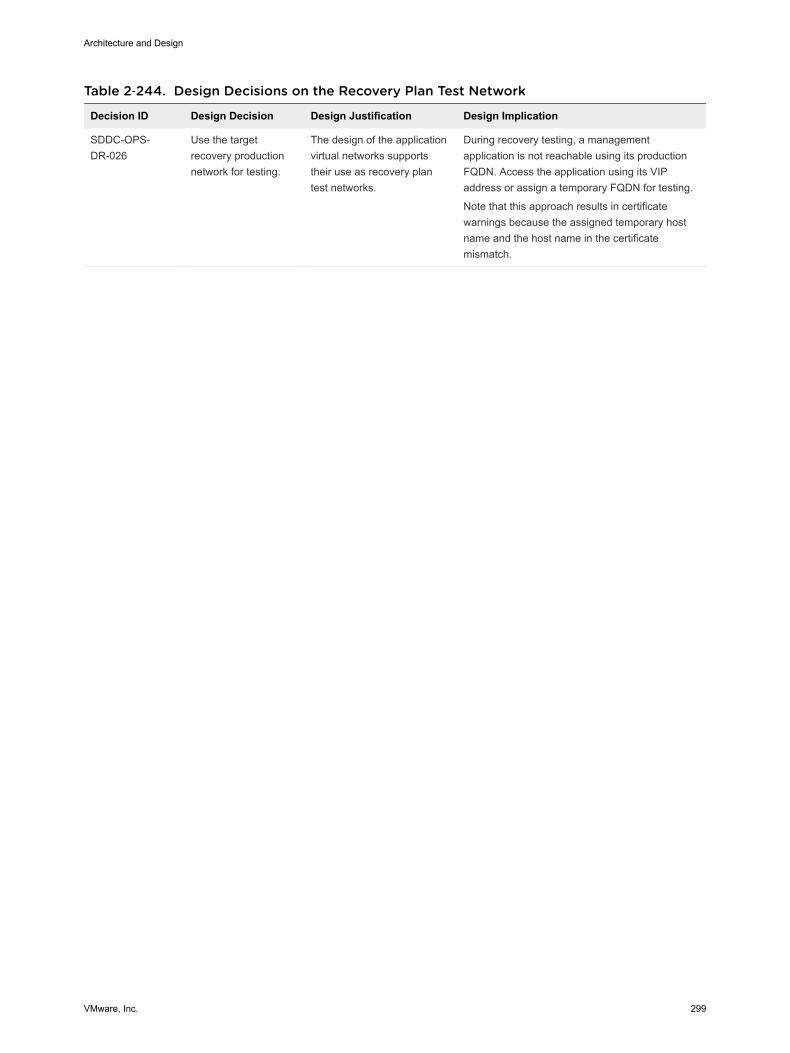
Table 2‑244. Design Decisions on the Recovery Plan Test Network
Decision ID Design Decision Design Justification Design Implication
SDDC-OPS-DR-026
Use the targetrecovery productionnetwork for testing.
The design of the applicationvirtual networks supportstheir use as recovery plantest networks.
During recovery testing, a managementapplication is not reachable using its productionFQDN. Access the application using its VIPaddress or assign a temporary FQDN for testing.
Note that this approach results in certificatewarnings because the assigned temporary hostname and the host name in the certificatemismatch.
Architecture and Design
VMware, Inc. 299