architecture and design - vmware validated design 5 · architecture and design thevmware validated...
TRANSCRIPT
Architecture and Design18 JUL 2019
VMware Validated Design 5.1VMware Validated Design for Software-Defined DataCenter 5.1

You can find the most up-to-date technical documentation on the VMware website at:
https://docs.vmware.com/
If you have comments about this documentation, submit your feedback to
VMware, Inc.3401 Hillview Ave.Palo Alto, CA 94304www.vmware.com
Copyright © 2016-2019 VMware, Inc. All rights reserved. Copyright and trademark information.
Architecture and Design
VMware, Inc. 2
Contents
About VMware Validated Design Architecture and Design 5
1 Architecture Overview 6Physical Infrastructure Architecture 8
Workload Domain Architecture 8
Cluster Types 9
Physical Network Architecture 11
Availability Zones and Regions 16
Virtual Infrastructure Architecture 17
Virtual Infrastructure Overview 18
Network Virtualization Components 21
Network Virtualization Services 22
Operations Management Architecture 25
ESXi Patching and Upgrade Architecture 25
vRealize Life Cycle Architecture 28
Monitoring Architecture 31
Logging Architecture 36
Product Diagnostics Architecture 42
Cloud Management Architecture 45
vRealize Automation Architecture 46
vRealize Business for Cloud Architecture 50
Business Continuity Architecture 53
Data Protection and Backup Architecture 53
Disaster Recovery Architecture 54
2 Detailed Design 57Physical Infrastructure Design 58
Physical Design Fundamentals 58
Physical Networking Design 64
Physical Storage Design 69
Virtual Infrastructure Design 79
ESXi Design 82
vCenter Server Design 84
Virtualization Network Design 103
NSX Design 119
Shared Storage Design 146
Operations Management Design 170
vSphere Update Manager Design 171
VMware, Inc. 3
vRealize Suite Lifecycle Manager Design 180
vRealize Operations Manager Design 197
vRealize Log Insight Design 215
VMware Skyline Design 236
Cloud Management Design 245
vRealize Automation Design 246
vRealize Business Design 282
vRealize Orchestrator Design 283
Business Continuity Design 290
Data Protection and Backup Design 290
Site Recovery Manager and vSphere Replication Design 294
Architecture and Design
VMware, Inc. 4
About VMware Validated DesignArchitecture and Design
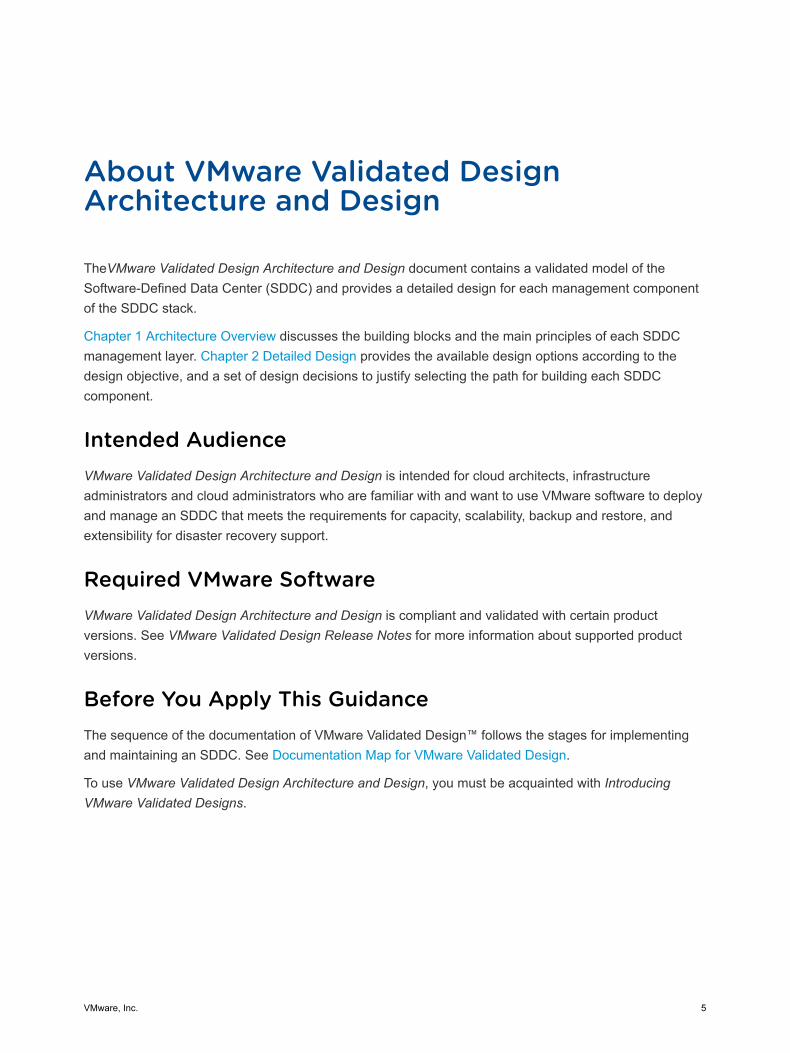
TheVMware Validated Design Architecture and Design document contains a validated model of theSoftware-Defined Data Center (SDDC) and provides a detailed design for each management componentof the SDDC stack.
Chapter 1 Architecture Overview discusses the building blocks and the main principles of each SDDCmanagement layer. Chapter 2 Detailed Design provides the available design options according to thedesign objective, and a set of design decisions to justify selecting the path for building each SDDCcomponent.
Intended AudienceVMware Validated Design Architecture and Design is intended for cloud architects, infrastructureadministrators and cloud administrators who are familiar with and want to use VMware software to deployand manage an SDDC that meets the requirements for capacity, scalability, backup and restore, andextensibility for disaster recovery support.
Required VMware SoftwareVMware Validated Design Architecture and Design is compliant and validated with certain productversions. See VMware Validated Design Release Notes for more information about supported productversions.
Before You Apply This GuidanceThe sequence of the documentation of VMware Validated Design™ follows the stages for implementingand maintaining an SDDC. See Documentation Map for VMware Validated Design.
To use VMware Validated Design Architecture and Design, you must be acquainted with IntroducingVMware Validated Designs.
VMware, Inc. 5
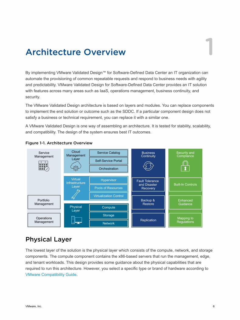
Architecture Overview 1By implementing VMware Validated Design™ for Software-Defined Data Center an IT organization canautomate the provisioning of common repeatable requests and respond to business needs with agilityand predictability. VMware Validated Design for Software-Defined Data Center provides an IT solutionwith features across many areas such as IaaS, operations management, business continuity, andsecurity.
The VMware Validated Design architecture is based on layers and modules. You can replace componentsto implement the end solution or outcome such as the SDDC. If a particular component design does notsatisfy a business or technical requirement, you can replace it with a similar one.
A VMware Validated Design is one way of assembling an architecture. It is tested for stability, scalability,and compatibility. The design of the system ensures best IT outcomes.
Figure 1-1. Architecture Overview
ServiceManagement
Portfolio Management
OperationsManagement
CloudManagement
Layer
Service Catalog
Self-Service Portal
Orchestration
BusinessContinuity
Fault Tolerance and Disaster
Recovery
Backup & Restore
Hypervisor
Pools of Resources
Virtualization Control
VirtualInfrastructure
Layer
Compute
Storage
Network
PhysicalLayer
Replication
Security and Compliance
Mapping to Regulations
Enhanced Guidance
Built-In Controls
Physical LayerThe lowest layer of the solution is the physical layer which consists of the compute, network, and storagecomponents. The compute component contains the x86-based servers that run the management, edge,and tenant workloads. This design provides some guidance about the physical capabilities that arerequired to run this architecture. However, you select a specific type or brand of hardware according toVMware Compatibility Guide.
VMware, Inc. 6
Virtual Infrastructure LayerThe virtual infrastructure layer is on top of the physical layer components. The virtual infrastructure layercontrols the access to the underlying physical infrastructure. It controls and allocates resources to themanagement and tenant workloads. The management workloads consist of elements in the virtualinfrastructure layer itself, together with elements in the cloud management, service management,business continuity, and security layers.
Cloud Management LayerThe cloud management layer is the top layer of the stack. Service consumption occurs at this layer.
This layer requests resources and orchestrates the actions of the lower layers from a user interface orover an API.
Service Management LayerWhen building any type of IT infrastructure, you use portfolio and operations management for continuousday-to-day service delivery. The service management area of this architecture focuses on operationsmanagement, in particular life cycle management, monitoring, alerting, and log management.
Operations Management LayerThe architecture of the operations management layer includes management components that support themain types of operations in an SDDC.
In the operations management layer, you monitor the underlying physical infrastructure and the virtualmanagement and tenant workloads in real time. Information is collected in the form of structured data(metrics) and unstructured data (logs). The operations management layer also retrieves the SDDCtopology, that is physical and virtual compute, networking, and storage resources, which are key inintelligent and dynamic operational management. The operations management layer consists primarily ofmonitoring and logging functionality.
Business Continuity LayerAn enterprise-ready system must contain elements to support business continuity by providing databackup, restoration, and disaster recovery. If data loss occurs, the right elements must be in place toprevent permanent loss of business critical data.
Security LayerAll systems must be secure by design. A secure design reduces risk and increases compliance whileproviding a governance structure. The security layer outlines the operations and setup that you mustprovide to implement an SDDC that is resilient to both internal and external threats.
This chapter includes the following topics:
Architecture and Design
VMware, Inc. 7
n Physical Infrastructure Architecture
n Virtual Infrastructure Architecture
n Operations Management Architecture
n Cloud Management Architecture
n Business Continuity Architecture
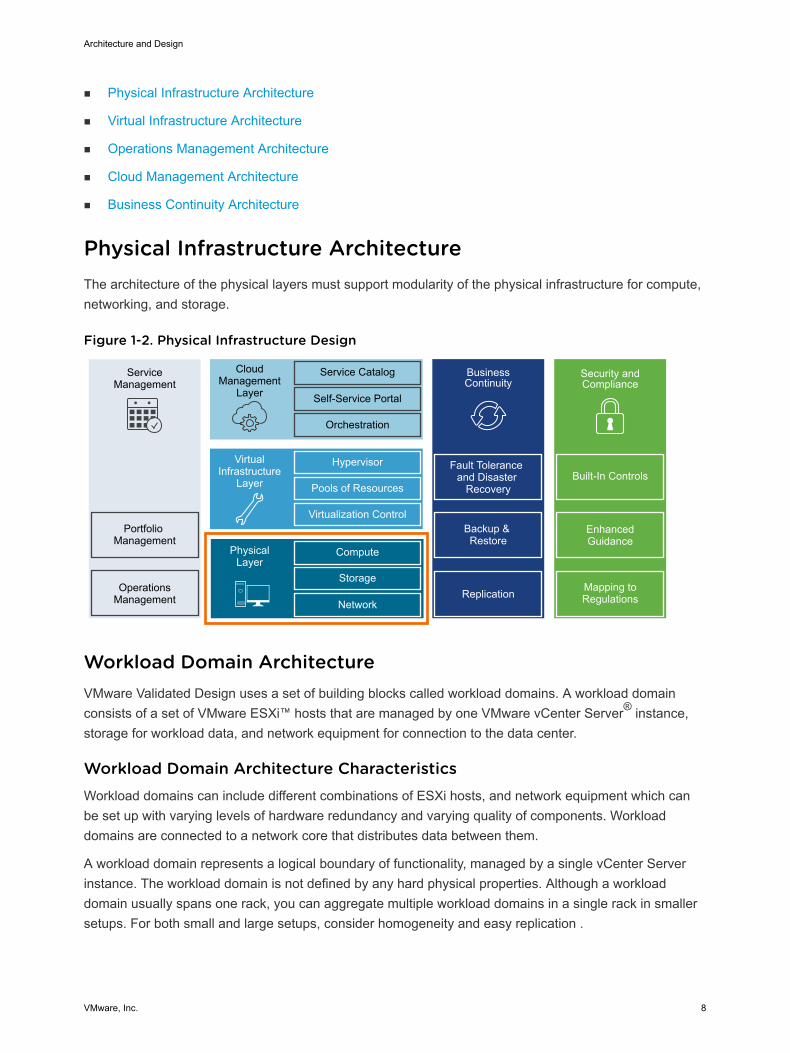
Physical Infrastructure Architecture The architecture of the physical layers must support modularity of the physical infrastructure for compute,networking, and storage.
Figure 1-2. Physical Infrastructure Design
ServiceManagement
Portfolio Management
OperationsManagement
CloudManagement
Layer
Service Catalog
Self-Service Portal
Orchestration
BusinessContinuity
Fault Tolerance and Disaster
Recovery
Backup & Restore
Hypervisor
Pools of Resources
Virtualization Control
VirtualInfrastructure
Layer
Compute
Storage
Network
PhysicalLayer
Replication
Security and Compliance
Mapping to Regulations
Enhanced Guidance
Built-In Controls
Workload Domain Architecture VMware Validated Design uses a set of building blocks called workload domains. A workload domainconsists of a set of VMware ESXi™ hosts that are managed by one VMware vCenter Server® instance,storage for workload data, and network equipment for connection to the data center.
Workload Domain Architecture CharacteristicsWorkload domains can include different combinations of ESXi hosts, and network equipment which canbe set up with varying levels of hardware redundancy and varying quality of components. Workloaddomains are connected to a network core that distributes data between them.
A workload domain represents a logical boundary of functionality, managed by a single vCenter Serverinstance. The workload domain is not defined by any hard physical properties. Although a workloaddomain usually spans one rack, you can aggregate multiple workload domains in a single rack in smallersetups. For both small and large setups, consider homogeneity and easy replication .
Architecture and Design
VMware, Inc. 8
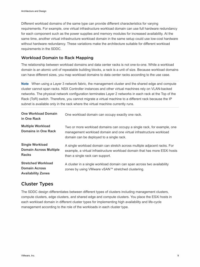
Different workload domains of the same type can provide different characteristics for varyingrequirements. For example, one virtual infrastructure workload domain can use full hardware redundancyfor each component such as the power supplies and memory modules for increased availability. At thesame time, another virtual infrastructure workload domain in the same setup could use low-cost hardwarewithout hardware redundancy. These variations make the architecture suitable for different workloadrequirements in the SDDC.
Workload Domain to Rack MappingThe relationship between workload domains and data center racks is not one-to-one. While a workloaddomain is an atomic unit of repeatable building blocks, a rack is a unit of size. Because workload domainscan have different sizes, you map workload domains to data center racks according to the use case.
Note When using a Layer 3 network fabric, the management cluster and the shared edge and computecluster cannot span racks. NSX Controller instances and other virtual machines rely on VLAN-backednetworks. The physical network configuration terminates Layer 2 networks in each rack at the Top of theRack (ToR) switch. Therefore, you cannot migrate a virtual machine to a different rack because the IPsubnet is available only in the rack where the virtual machine currently runs.
One Workload Domainin One Rack
One workload domain can occupy exactly one rack.
Multiple WorkloadDomains in One Rack
Two or more workload domains can occupy a single rack, for example, onemanagement workload domain and one virtual infrastructure workloaddomain can be deployed to a single rack.
Single WorkloadDomain Across MultipleRacks
A single workload domain can stretch across multiple adjacent racks. Forexample, a virtual infrastructure workload domain that has more ESXi hoststhan a single rack can support.
Stretched WorkloadDomain AcrossAvailability Zones
A cluster in a single workload domain can span across two availabilityzones by using VMware vSAN™ stretched clustering.
Cluster Types The SDDC design differentiates between different types of clusters including management clusters,compute clusters, edge clusters, and shared edge and compute clusters. You place the ESXi hosts ineach workload domain in different cluster types for implementing high availability and life-cyclemanagement according to the role of the workloads in each cluster type.
Architecture and Design
VMware, Inc. 9
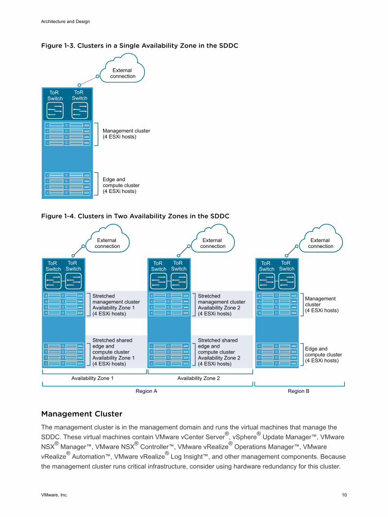
Figure 1-3. Clusters in a Single Availability Zone in the SDDC
ToR Switch
ToR Switch
Management cluster(4 ESXi hosts)
Edge and compute cluster(4 ESXi hosts)
External connection
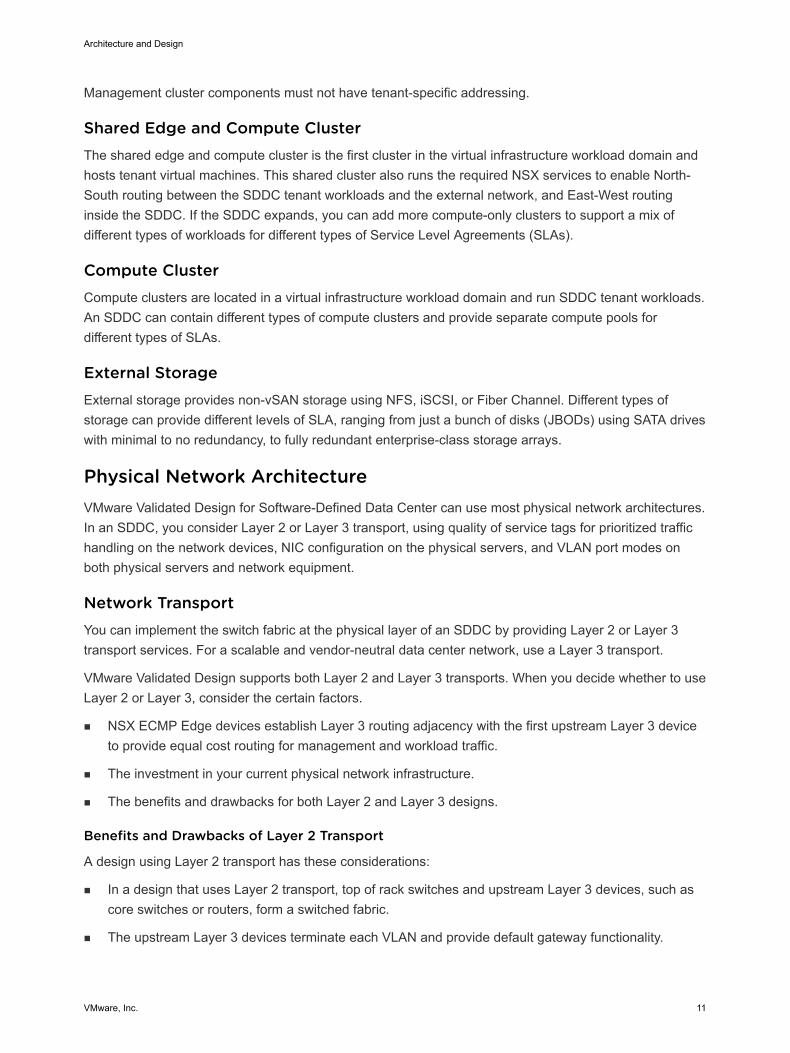
Figure 1-4. Clusters in Two Availability Zones in the SDDC
Availability Zone 1
Management cluster(4 ESXi hosts)
Еdge andcompute cluster(4 ESXi hosts)
ToR Switch
ToR Switch
Stretchedmanagement clusterAvailability Zone 1(4 ESXi hosts)
Stretched sharededge andcompute clusterAvailability Zone 1(4 ESXi hosts)
External connection
External connection
External connection
ToR Switch
ToR Switch
Stretchedmanagement clusterAvailability Zone 2(4 ESXi hosts)
Stretched sharededge and compute clusterAvailability Zone 2(4 ESXi hosts)
ToR Switch
ToR Switch
Availability Zone 2
Region A Region B
Management ClusterThe management cluster is in the management domain and runs the virtual machines that manage theSDDC. These virtual machines contain VMware vCenter Server®, vSphere® Update Manager™, VMwareNSX® Manager™, VMware NSX® Controller™, VMware vRealize® Operations Manager™, VMwarevRealize® Automation™, VMware vRealize® Log Insight™, and other management components. Becausethe management cluster runs critical infrastructure, consider using hardware redundancy for this cluster.
Architecture and Design
VMware, Inc. 10
Management cluster components must not have tenant-specific addressing.
Shared Edge and Compute ClusterThe shared edge and compute cluster is the first cluster in the virtual infrastructure workload domain andhosts tenant virtual machines. This shared cluster also runs the required NSX services to enable North-South routing between the SDDC tenant workloads and the external network, and East-West routinginside the SDDC. If the SDDC expands, you can add more compute-only clusters to support a mix ofdifferent types of workloads for different types of Service Level Agreements (SLAs).
Compute ClusterCompute clusters are located in a virtual infrastructure workload domain and run SDDC tenant workloads.An SDDC can contain different types of compute clusters and provide separate compute pools fordifferent types of SLAs.
External StorageExternal storage provides non-vSAN storage using NFS, iSCSI, or Fiber Channel. Different types ofstorage can provide different levels of SLA, ranging from just a bunch of disks (JBODs) using SATA driveswith minimal to no redundancy, to fully redundant enterprise-class storage arrays.
Physical Network Architecture VMware Validated Design for Software-Defined Data Center can use most physical network architectures.In an SDDC, you consider Layer 2 or Layer 3 transport, using quality of service tags for prioritized traffichandling on the network devices, NIC configuration on the physical servers, and VLAN port modes onboth physical servers and network equipment.
Network Transport You can implement the switch fabric at the physical layer of an SDDC by providing Layer 2 or Layer 3transport services. For a scalable and vendor-neutral data center network, use a Layer 3 transport.
VMware Validated Design supports both Layer 2 and Layer 3 transports. When you decide whether to useLayer 2 or Layer 3, consider the certain factors.
n NSX ECMP Edge devices establish Layer 3 routing adjacency with the first upstream Layer 3 deviceto provide equal cost routing for management and workload traffic.
n The investment in your current physical network infrastructure.
n The benefits and drawbacks for both Layer 2 and Layer 3 designs.
Benefits and Drawbacks of Layer 2 Transport
A design using Layer 2 transport has these considerations:
n In a design that uses Layer 2 transport, top of rack switches and upstream Layer 3 devices, such ascore switches or routers, form a switched fabric.
n The upstream Layer 3 devices terminate each VLAN and provide default gateway functionality.
Architecture and Design
VMware, Inc. 11
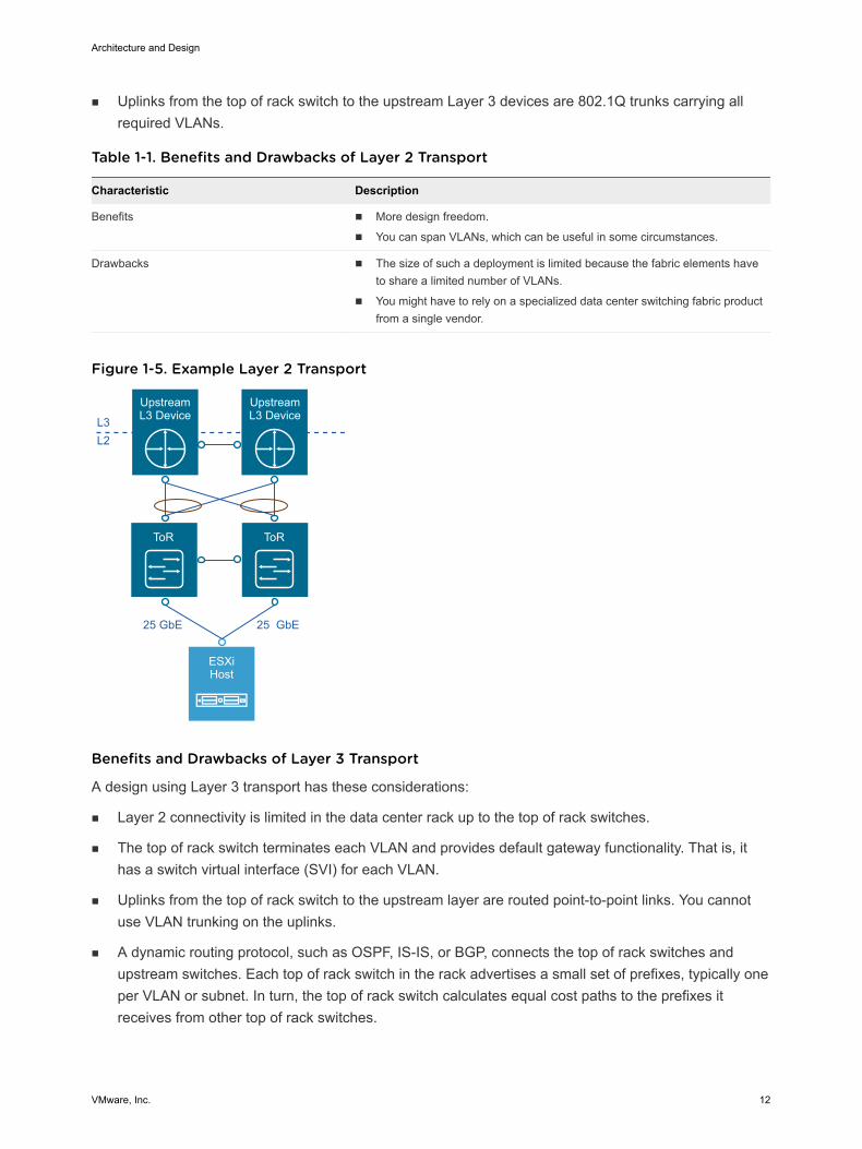
n Uplinks from the top of rack switch to the upstream Layer 3 devices are 802.1Q trunks carrying allrequired VLANs.
Table 1-1. Benefits and Drawbacks of Layer 2 Transport
Characteristic Description
Benefits n More design freedom.
n You can span VLANs, which can be useful in some circumstances.
Drawbacks n The size of such a deployment is limited because the fabric elements haveto share a limited number of VLANs.
n You might have to rely on a specialized data center switching fabric productfrom a single vendor.
Figure 1-5. Example Layer 2 Transport
ToR ToR
ESXiHost
Upstream L3 DeviceL3
25 GbE 25 GbE
L2
Upstream L3 Device
Benefits and Drawbacks of Layer 3 Transport
A design using Layer 3 transport has these considerations:
n Layer 2 connectivity is limited in the data center rack up to the top of rack switches.
n The top of rack switch terminates each VLAN and provides default gateway functionality. That is, ithas a switch virtual interface (SVI) for each VLAN.
n Uplinks from the top of rack switch to the upstream layer are routed point-to-point links. You cannotuse VLAN trunking on the uplinks.
n A dynamic routing protocol, such as OSPF, IS-IS, or BGP, connects the top of rack switches andupstream switches. Each top of rack switch in the rack advertises a small set of prefixes, typically oneper VLAN or subnet. In turn, the top of rack switch calculates equal cost paths to the prefixes itreceives from other top of rack switches.
Architecture and Design
VMware, Inc. 12
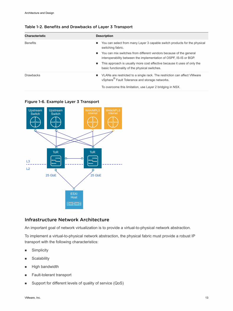
Table 1-2. Benefits and Drawbacks of Layer 3 Transport
Characteristic Description
Benefits n You can select from many Layer 3 capable switch products for the physicalswitching fabric.
n You can mix switches from different vendors because of the generalinteroperability between the implementation of OSPF, IS-IS or BGP.
n This approach is usually more cost effective because it uses of only thebasic functionality of the physical switches.
Drawbacks n VLANs are restricted to a single rack. The restriction can affect VMwarevSphere® Fault Tolerance and storage networks.
To overcome this limitation, use Layer 2 bridging in NSX.
Figure 1-6. Example Layer 3 Transport
ToR
L3
ESXiHost
UpstreamSwitch
UpstreamSwitch
WAN/MPLSInternet
WAN/MPLSInternet
ToR
L2
25 GbE25 GbE
Infrastructure Network Architecture An important goal of network virtualization is to provide a virtual-to-physical network abstraction.
To implement a virtual-to-physical network abstraction, the physical fabric must provide a robust IPtransport with the following characteristics:
n Simplicity
n Scalability
n High bandwidth
n Fault-tolerant transport
n Support for different levels of quality of service (QoS)
Architecture and Design
VMware, Inc. 13
Simplicity and Scalability
Simplicity and scalability are the first and most critical requirements for networking.
Simplicity
Switch configuration in a data center must be simple. General or global configuration such as AAA,SNMP, syslog, NTP, and others should be replicated line by line, independent of the position of theswitches. A central management capability to configure all switches at once is an alternative.
Restrict configurations that are unique to the switches such as multi-chassis link aggregation groups,VLAN IDs, and dynamic routing protocol configuration.
Scalability
Scalability factors include, but are not limited to, the following:
n Number of racks supported in a fabric.
n Amount of bandwidth between any two racks in a data center.
n Number of paths between racks.
The total number of ports available across all switches and the oversubscription that is acceptabledetermine the number of racks supported in a fabric. Different racks might host different types ofinfrastructure, which can result in different bandwidth requirements.
n Racks with IP storage systems might receive or source more traffic than other racks.
n Compute racks, such as racks hosting hypervisors with virtual machines, might have differentbandwidth requirements than shared edge and compute racks, which provide connectivity to theoutside world.
Link speed and number of links vary to satisfy different bandwidth demands. You can modify them foreach rack.
Quality of Service Differentiation
Virtualized environments carry different types of traffic, including tenant, storage and management traffic,across the switching infrastructure. Each traffic type has different characteristics and has differentdemands on the physical switching infrastructure.
n Management traffic, although typically low in volume, is critical for controlling physical and virtualnetwork state.
n IP storage traffic is typically high in volume and generally remains in the boundaries of a data center.
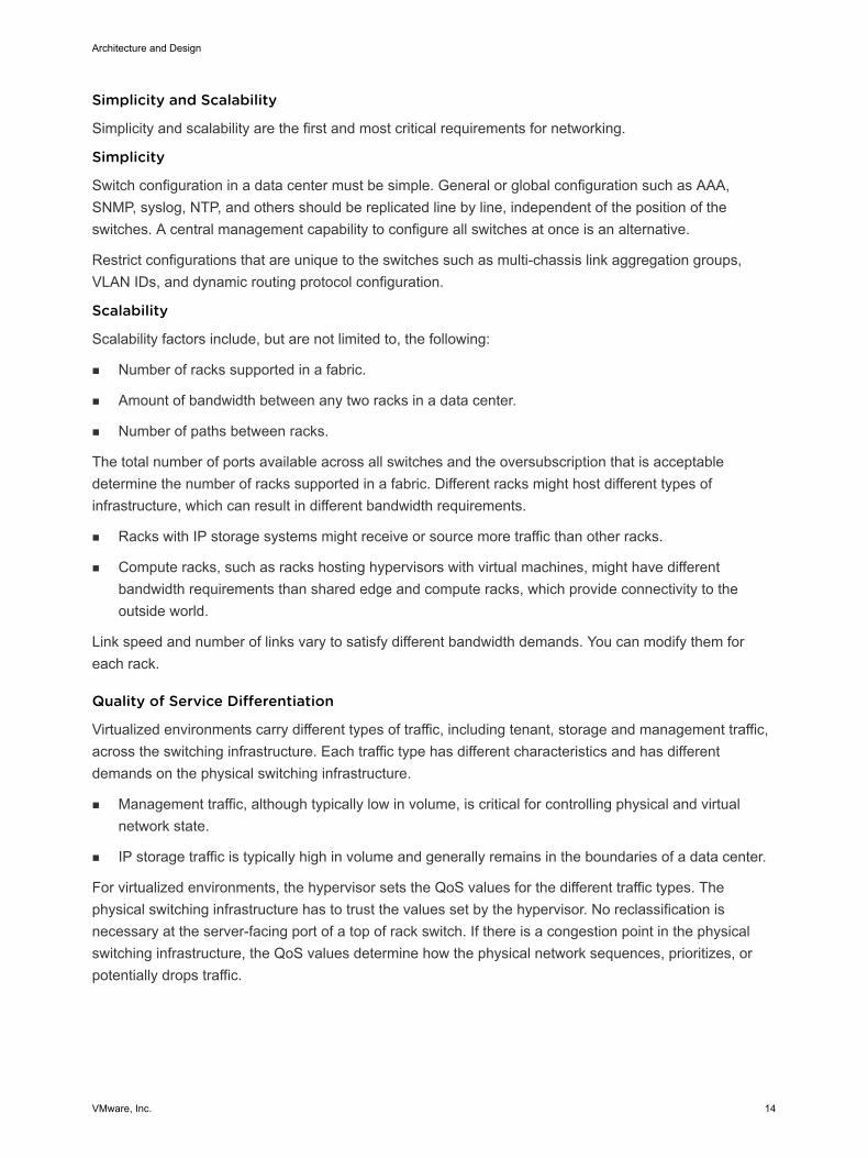
For virtualized environments, the hypervisor sets the QoS values for the different traffic types. Thephysical switching infrastructure has to trust the values set by the hypervisor. No reclassification isnecessary at the server-facing port of a top of rack switch. If there is a congestion point in the physicalswitching infrastructure, the QoS values determine how the physical network sequences, prioritizes, orpotentially drops traffic.
Architecture and Design
VMware, Inc. 14
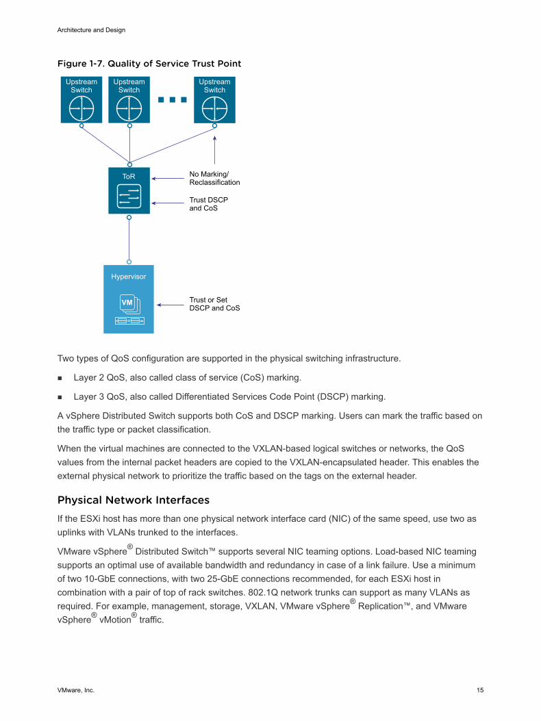
Figure 1-7. Quality of Service Trust Point
VM
ToR
Trust or Set DSCP and CoS
Trust DSCP and CoS
Hypervisor
No Marking/Reclassification
Upstream Switch
Upstream Switch
Upstream Switch
Two types of QoS configuration are supported in the physical switching infrastructure.
n Layer 2 QoS, also called class of service (CoS) marking.
n Layer 3 QoS, also called Differentiated Services Code Point (DSCP) marking.
A vSphere Distributed Switch supports both CoS and DSCP marking. Users can mark the traffic based onthe traffic type or packet classification.
When the virtual machines are connected to the VXLAN-based logical switches or networks, the QoSvalues from the internal packet headers are copied to the VXLAN-encapsulated header. This enables theexternal physical network to prioritize the traffic based on the tags on the external header.
Physical Network Interfaces If the ESXi host has more than one physical network interface card (NIC) of the same speed, use two asuplinks with VLANs trunked to the interfaces.
VMware vSphere® Distributed Switch™ supports several NIC teaming options. Load-based NIC teamingsupports an optimal use of available bandwidth and redundancy in case of a link failure. Use a minimumof two 10-GbE connections, with two 25-GbE connections recommended, for each ESXi host incombination with a pair of top of rack switches. 802.1Q network trunks can support as many VLANs asrequired. For example, management, storage, VXLAN, VMware vSphere® Replication™, and VMwarevSphere® vMotion® traffic.
Architecture and Design
VMware, Inc. 15
Availability Zones and Regions In an SDDC, availability zones are collections of infrastructure components. Availability zones are isolatedfrom each other to prevent the propagation of failure or outage across the data center. Use regions toplace workloads closer to your customers, comply with data privacy laws and restrictions, and supportdisaster recovery solutions for the entire SDDC.
This design uses a protected region (Region A) for SDDC management components with one or twoavailability zones and recovery region (Region B) with a single availability zone. You can place workloadsin each availability zone and region. Usually, multiple availability zones form a single region.
This VMware Validated Design uses two regions, with the option to use one or two availability zones inRegion A and single availability zone in Region B. You can expand the design to include multipleavailability zones.
Figure 1-8. Availability Zones and Regions
AvailabilityZone 1
AvailabilityZone 1
AvailabilityZone 2
FutureAvailability
ZoneFuture
AvailabilityZone
Region B: LAXRegion A: SFO
Availability Zones In a region, each availability zone is isolated from the other availability zones to prevent reproducingfailure or outage across zone boundaries.
Using multiple availability zones provides high availability through redundancy.
Architecture and Design
VMware, Inc. 16
Table 1-3. Characteristics of Availability Zones
Availability Zone Characteristic Description
Outage prevention You avoid outages and improve SLAs. An outage that is caused by external factors, suchas power supply, cooling, and physical integrity, affects only one zone. These factors do notcause outage in other zones except in the case of major disasters.
Reliability Each availability zone runs on its own physically distinct, independent infrastructure, and isengineered to be highly reliable. Each zone should have independent power, cooling,network, and security. Do not share common points of failures in a physical data center,like generators and cooling equipment, across availability zones. Additionally, these zonesshould be physically separate so that even uncommon disasters affect only one zone.
Availability zones are either two distinct data centers in a metro distance, or two safety orfire sectors (data halls) in the same large-scale data center.
Distance between zones Multiple availability zones belong to a single region. The physical distance betweenavailability zones is short enough to offer low, single-digit latency (less than 5 ms) andlarge bandwidth (10 Gbps or greater) between the zones.
You can operate workloads across multiple availability zones in the same region as if theywere part of a single virtual data center. This architecture supports high availability that issuitable for mission critical applications.
If the distance between two locations of equipment becomes too large, these locations canno longer function as two availability zones in the same region and must be designed asseparate regions.
Regions By using multiple regions, you can place workloads closer to your customers. For example, you canoperate one region on the US East Coast and one region on the US West Coast, or operate a region inEurope and another region in the US.
Using regions has the following advantages:
n Support disaster recovery solutions. One region can be the primary site and another region can bethe recovery site.
n Address data privacy laws and restrictions in certain countries by storing tenant data in a region in thesame country.
The distance between regions can be large. The latency between regions must be less than 100 ms.
This validated design uses two example regions: Region A, in San Francisco (SFO), and Region B, in LosAngeles (LAX).
Virtual Infrastructure Architecture The virtual infrastructure is the foundation of the SDDC. It contains the software-defined infrastructure,software-defined networking and software-defined storage. The virtual infrastructure layer runs theoperations management layer and the Cloud Management Platform.
Architecture and Design
VMware, Inc. 17
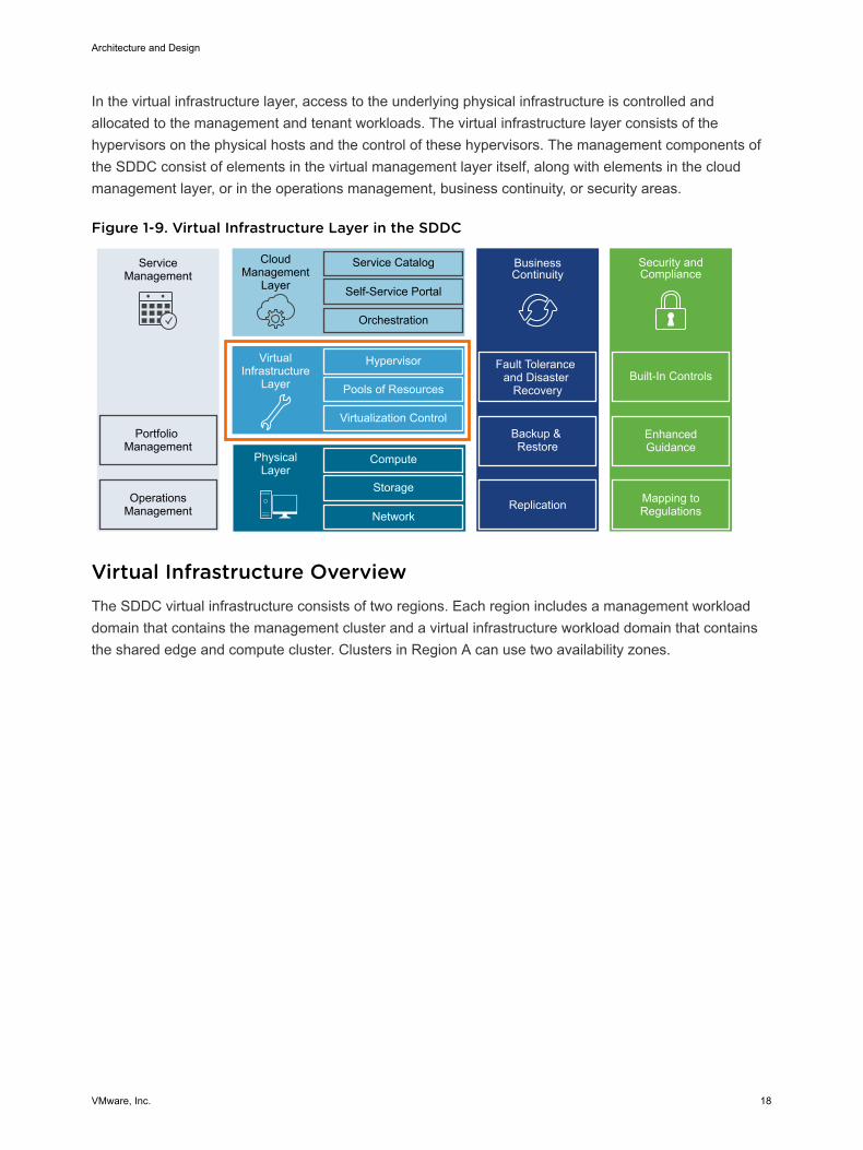
In the virtual infrastructure layer, access to the underlying physical infrastructure is controlled andallocated to the management and tenant workloads. The virtual infrastructure layer consists of thehypervisors on the physical hosts and the control of these hypervisors. The management components ofthe SDDC consist of elements in the virtual management layer itself, along with elements in the cloudmanagement layer, or in the operations management, business continuity, or security areas.
Figure 1-9. Virtual Infrastructure Layer in the SDDC
ServiceManagement
Portfolio Management
OperationsManagement
CloudManagement
Layer
Service Catalog
Self-Service Portal
Orchestration
BusinessContinuity
Fault Tolerance and Disaster
Recovery
Backup & Restore
Hypervisor
Pools of Resources
Virtualization Control
VirtualInfrastructure
Layer
Compute
Storage
Network
PhysicalLayer
Replication
Security and Compliance
Mapping to Regulations
Enhanced Guidance
Built-In Controls
Virtual Infrastructure Overview The SDDC virtual infrastructure consists of two regions. Each region includes a management workloaddomain that contains the management cluster and a virtual infrastructure workload domain that containsthe shared edge and compute cluster. Clusters in Region A can use two availability zones.
Architecture and Design
VMware, Inc. 18
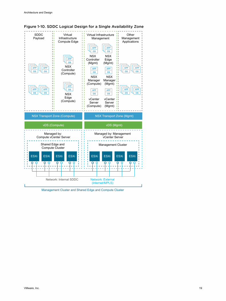
Figure 1-10. SDDC Logical Design for a Single Availability Zone
APP
OSAPP
OS
APP
OSAPP
OS
APP
OSAPP
OS
APP
OSAPP
OS
APP
OS
APP
OS
APP
OSAPP
OS
APP
OSAPP
OS
APP
OSAPP
OS
Virtual InfrastructureManagement
NSXController
(Mgmt)
OtherManagementApplications
NSXEdge
(Mgmt)
NSXManager(Mgmt)
NSXManager
(Compute)
NSXEdge
(Compute)
NSXController(Compute)
ESXi ESXi ESXi ESXi ESXi ESXi
SDDCPayload
Virtual Infrastructure Compute Edge
NSX Transport Zone (Compute)
vDS (Compute) vDS (Mgmt)
NSX Transport Zone (Mgmt)
Shared Edge and Compute Cluster
Management Cluster
Managed by: Compute vCenter Server
Managed by: Management vCenter Server
Network: External(Internet/MPLS)
Network: Internal SDDC
Management Cluster and Shared Edge and Compute Cluster
vCenterServer(Mgmt)
vCenterServer
(Compute)
ESXiESXi
Architecture and Design
VMware, Inc. 19
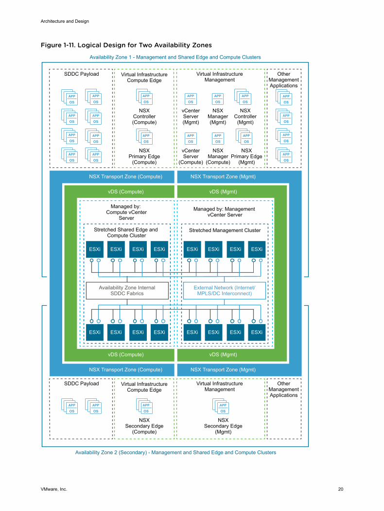
Figure 1-11. Logical Design for Two Availability Zones
APP
OS
APP
OSAPP
OSAPP
OS
APP
OSAPP
OS
APP
OS
APP
OS
APP
OSAPP
OS
APP
OS
APP
OS
APP
OS
APP
OSAPP
OS
APP
OSAPP
OS
APP
OS
APP
OS
APP
OS
APP
OSAPP
OSAPP
OSAPP
OS
ESXi ESXi
Virtual InfrastructureCompute Edge
NSXPrimary Edge
(Compute)
NSXController(Compute)
ESXi
SDDC Payload
NSX Transport Zone (Compute)
vDS (Compute)
Stretched Shared Edge and Compute Cluster
Stretched Management Cluster
Managed by: Compute vCenter
Server
Managed by: Management vCenter Server
External Network (Internet/MPLS/DC Interconnect)
Availability Zone InternalSDDC Fabrics
Availability Zone 1 - Management and Shared Edge and Compute Clusters
ESXi
Virtual InfrastructureManagement
NSXController
(Mgmt)
NSXPrimary Edge
(Mgmt)
NSXManager(Mgmt)
NSXManager
(Compute)
vCenterServer(Mgmt)
vCenterServer
(Compute)
Availability Zone 2 (Secondary) - Management and Shared Edge and Compute Clusters
OtherManagementApplications
ESXiESXi ESXiESXi
ESXiESXi ESXiESXiESXiESXi ESXiESXi
NSX Transport Zone (Compute)
vDS (Compute)
NSX Transport Zone (Mgmt)
vDS (Mgmt)
NSX Transport Zone (Mgmt)
vDS (Mgmt)
Virtual InfrastructureCompute Edge
NSXSecondary Edge
(Compute)
SDDC Payload Virtual InfrastructureManagement
NSXSecondary Edge
(Mgmt)
OtherManagementApplications
Architecture and Design
VMware, Inc. 20
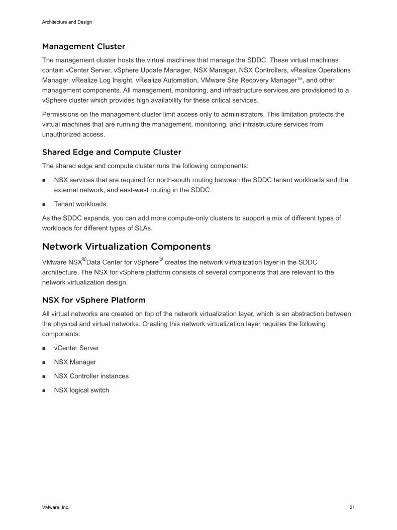
Management ClusterThe management cluster hosts the virtual machines that manage the SDDC. These virtual machinescontain vCenter Server, vSphere Update Manager, NSX Manager, NSX Controllers, vRealize OperationsManager, vRealize Log Insight, vRealize Automation, VMware Site Recovery Manager™, and othermanagement components. All management, monitoring, and infrastructure services are provisioned to avSphere cluster which provides high availability for these critical services.
Permissions on the management cluster limit access only to administrators. This limitation protects thevirtual machines that are running the management, monitoring, and infrastructure services fromunauthorized access.
Shared Edge and Compute ClusterThe shared edge and compute cluster runs the following components:
n NSX services that are required for north-south routing between the SDDC tenant workloads and theexternal network, and east-west routing in the SDDC.
n Tenant workloads.
As the SDDC expands, you can add more compute-only clusters to support a mix of different types ofworkloads for different types of SLAs.
Network Virtualization Components VMware NSX®Data Center for vSphere® creates the network virtualization layer in the SDDCarchitecture. The NSX for vSphere platform consists of several components that are relevant to thenetwork virtualization design.
NSX for vSphere PlatformAll virtual networks are created on top of the network virtualization layer, which is an abstraction betweenthe physical and virtual networks. Creating this network virtualization layer requires the followingcomponents:
n vCenter Server
n NSX Manager
n NSX Controller instances
n NSX logical switch
Architecture and Design
VMware, Inc. 21
These components are separated in different planes to create communications boundaries and provideisolation of workload data from system control messages.
Data plane The data plane handles the workload data only. NSX logical switchessegregate unrelated workload data. Data is carried over a designatedtransport network in the physical network. NSX logical switches, distributedrouting, and distributed firewall are also implemented in the data plane.
Control plane The control plane handles network virtualization control messages. Controlmessages are used to set up networking attributes on NSX logical switchinstances, and to configure and manage distributed routing and firewallcomponents on each ESXi host. Control plane communication is carried onsecure physical networks (VLANs) that are isolated from the transportnetworks used for the data plane.
Management plane The network virtualization orchestration occurs in the management plane.In this layer, cloud management platforms such as vRealize Automationcan request, consume, and destroy networking resources for virtualworkloads. The cloud management platform directs requests to vCenterServer to create and manage virtual machines, and to NSX Manager toconsume networking resources.
See the Network Virtualization definition.
Network Virtualization Services Network virtualization services include logical switches, logical routers, logical firewalls, and othercomponents of NSX for vSphere.
Logical SwitchesNSX logical switches create logically abstracted segments to which tenant virtual machines can connect.A single logical switch is mapped to a unique VXLAN segment ID and is distributed across the ESXihypervisors within a transport zone. This logical switch configuration provides support for line-rateswitching in the hypervisor without creating constraints of VLAN sprawl or spanning tree issues.
Universal Distributed Logical RouterUniversal distributed logical router (UDLR) in NSX for vSphere performs routing operations in thevirtualized space (between VMs, on VXLAN- or VLAN-backed port groups). UDLR has the followingfeatures:
n High performance, low overhead first hop routing
n Scaling the number of hosts
n Support for up to 1,000 logical interfaces (LIFs) on each distributed logical router
Architecture and Design
VMware, Inc. 22
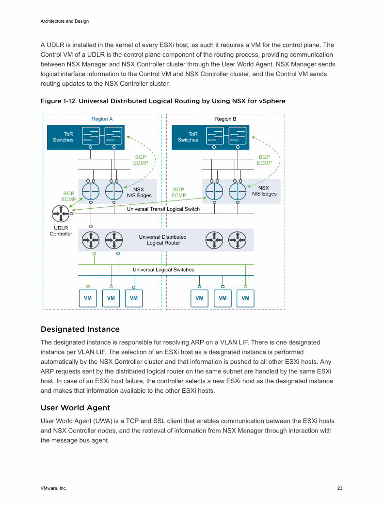
A UDLR is installed in the kernel of every ESXi host, as such it requires a VM for the control plane. TheControl VM of a UDLR is the control plane component of the routing process, providing communicationbetween NSX Manager and NSX Controller cluster through the User World Agent. NSX Manager sendslogical interface information to the Control VM and NSX Controller cluster, and the Control VM sendsrouting updates to the NSX Controller cluster.
Figure 1-12. Universal Distributed Logical Routing by Using NSX for vSphere
Region A
Universal Transit Logical Switch
Universal Distributed Logical Router
Universal Logical Switches
NSX N/S Edges
UDLRController
BGPECMP
BGPECMPBGP
ECMP
NSX N/S Edges
BGPECMP
Region B
ToRSwitches
ToRSwitches
Designated InstanceThe designated instance is responsible for resolving ARP on a VLAN LIF. There is one designatedinstance per VLAN LIF. The selection of an ESXi host as a designated instance is performedautomatically by the NSX Controller cluster and that information is pushed to all other ESXi hosts. AnyARP requests sent by the distributed logical router on the same subnet are handled by the same ESXihost. In case of an ESXi host failure, the controller selects a new ESXi host as the designated instanceand makes that information available to the other ESXi hosts.
User World AgentUser World Agent (UWA) is a TCP and SSL client that enables communication between the ESXi hostsand NSX Controller nodes, and the retrieval of information from NSX Manager through interaction withthe message bus agent.
Architecture and Design
VMware, Inc. 23
Edge Services GatewayWhile the UDLR provides VM-to-VM or east-west routing, the NSX Edge services gateway providesnorth-south connectivity, by peering with upstream layer 3 devices, thereby enabling tenants to accesspublic networks.
Logical FirewallNSX Logical Firewall provides security mechanisms for dynamic virtual data centers.
n The Distributed Firewall allows you to segment virtual data center entities like virtual machines.Segmentation can be based on VM names and attributes, user identity, vCenter Server objects likedata centers, and ESXi hosts, or can be based on traditional networking attributes like IPaddresses, port groups, and so on.
n The Edge Firewall component helps you meet important perimeter security requirements, such asbuilding DMZs based on IP/VLAN constructs, tenant-to-tenant isolation in multi-tenant virtual datacenters, Network Address Translation (NAT), partner (extranet) VPNs, and user-based SSL VPNs.
The Flow Monitoring feature displays network activity between virtual machines at the application protocollevel. You can use this information to audit network traffic, define and refine firewall policies, and identifythreats to your network.
Logical Virtual Private Networks (VPNs)SSL VPN-Plus allows remote users to access private corporate applications. IPSec VPN offers site-to-siteconnectivity between an NSX Edge instance and remote sites. L2 VPN allows you to extend yourdatacenter by allowing virtual machines to retain network connectivity across geographical boundaries.
Logical Load BalancerThe NSX Edge load balancer enables network traffic to follow multiple paths to a specific destination. Itdistributes incoming service requests evenly among multiple servers in such a way that the loaddistribution is transparent to users. Load balancing thus helps in achieving optimal resource utilization,improving throughput, reducing response time, and avoiding overload. NSX Edge provides load balancingup to Layer 7.
Service ComposerService Composer helps you provision and assign network and security services to applications in avirtual infrastructure. You map these services to a security group, and the services are applied to thevirtual machines in the security group.
NSX ExtensibilityVMware partners integrate their solutions with the NSX for vSphere platform to enable an integratedexperience across the entire SDDC. Data center operators can provision complex, multi-tier virtualnetworks in seconds, independent of the underlying network topology or components.
Architecture and Design
VMware, Inc. 24
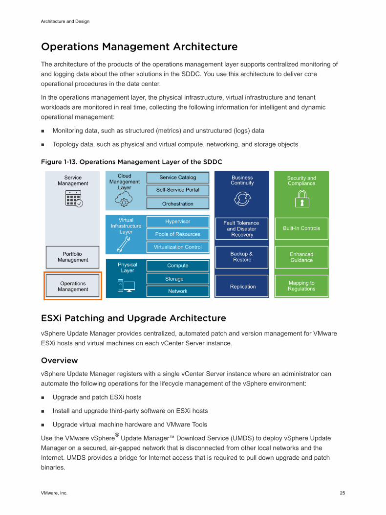
Operations Management Architecture The architecture of the products of the operations management layer supports centralized monitoring ofand logging data about the other solutions in the SDDC. You use this architecture to deliver coreoperational procedures in the data center.
In the operations management layer, the physical infrastructure, virtual infrastructure and tenantworkloads are monitored in real time, collecting the following information for intelligent and dynamicoperational management:
n Monitoring data, such as structured (metrics) and unstructured (logs) data
n Topology data, such as physical and virtual compute, networking, and storage objects
Figure 1-13. Operations Management Layer of the SDDC
ServiceManagement
Portfolio Management
OperationsManagement
CloudManagement
Layer
Service Catalog
Self-Service Portal
Orchestration
BusinessContinuity
Fault Tolerance and Disaster
Recovery
Backup & Restore
Hypervisor
Pools of Resources
Virtualization Control
VirtualInfrastructure
Layer
Compute
Storage
Network
PhysicalLayer
Replication
Security and Compliance
Mapping to Regulations
Enhanced Guidance
Built-In Controls
ESXi Patching and Upgrade Architecture vSphere Update Manager provides centralized, automated patch and version management for VMwareESXi hosts and virtual machines on each vCenter Server instance.
OverviewvSphere Update Manager registers with a single vCenter Server instance where an administrator canautomate the following operations for the lifecycle management of the vSphere environment:
n Upgrade and patch ESXi hosts
n Install and upgrade third-party software on ESXi hosts
n Upgrade virtual machine hardware and VMware Tools
Use the VMware vSphere® Update Manager™ Download Service (UMDS) to deploy vSphere UpdateManager on a secured, air-gapped network that is disconnected from other local networks and theInternet. UMDS provides a bridge for Internet access that is required to pull down upgrade and patchbinaries.
Architecture and Design
VMware, Inc. 25
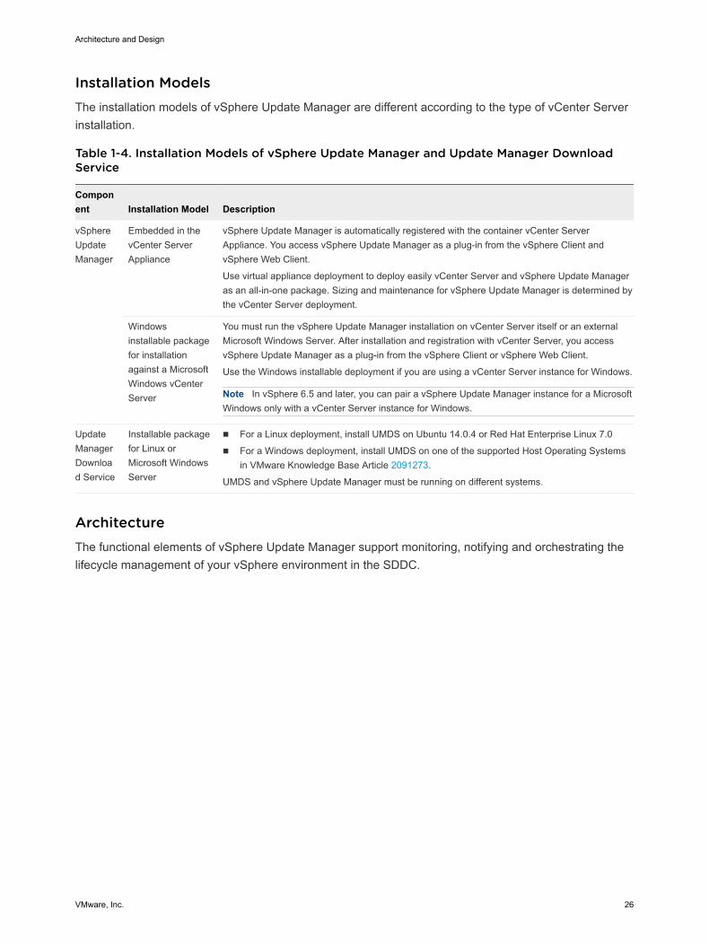
Installation ModelsThe installation models of vSphere Update Manager are different according to the type of vCenter Serverinstallation.
Table 1-4. Installation Models of vSphere Update Manager and Update Manager DownloadService
Component Installation Model Description
vSphereUpdateManager
Embedded in thevCenter ServerAppliance
vSphere Update Manager is automatically registered with the container vCenter ServerAppliance. You access vSphere Update Manager as a plug-in from the vSphere Client andvSphere Web Client.
Use virtual appliance deployment to deploy easily vCenter Server and vSphere Update Manageras an all-in-one package. Sizing and maintenance for vSphere Update Manager is determined bythe vCenter Server deployment.
Windowsinstallable packagefor installationagainst a MicrosoftWindows vCenterServer
You must run the vSphere Update Manager installation on vCenter Server itself or an externalMicrosoft Windows Server. After installation and registration with vCenter Server, you accessvSphere Update Manager as a plug-in from the vSphere Client or vSphere Web Client.
Use the Windows installable deployment if you are using a vCenter Server instance for Windows.
Note In vSphere 6.5 and later, you can pair a vSphere Update Manager instance for a MicrosoftWindows only with a vCenter Server instance for Windows.
UpdateManagerDownload Service
Installable packagefor Linux orMicrosoft WindowsServer
n For a Linux deployment, install UMDS on Ubuntu 14.0.4 or Red Hat Enterprise Linux 7.0
n For a Windows deployment, install UMDS on one of the supported Host Operating Systemsin VMware Knowledge Base Article 2091273.
UMDS and vSphere Update Manager must be running on different systems.
ArchitectureThe functional elements of vSphere Update Manager support monitoring, notifying and orchestrating thelifecycle management of your vSphere environment in the SDDC.
Architecture and Design
VMware, Inc. 26
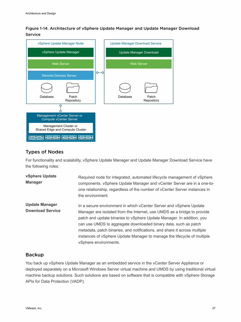
Figure 1-14. Architecture of vSphere Update Manager and Update Manager DownloadService
Management Cluster or Shared Edge and Compute Cluster
PatchRepository
PatchRepository
vSphere Update Manager
Web Server
Remote Devices Server
Database
vSphere Update Manager Node
Update Manager Download
Web Server
Database
Update Manager Download Service
Management vCenter Server orCompute vCenter Server
Types of NodesFor functionality and scalability, vSphere Update Manager and Update Manager Download Service havethe following roles:
vSphere UpdateManager
Required node for integrated, automated lifecycle management of vSpherecomponents. vSphere Update Manager and vCenter Server are in a one-to-one relationship, regardless of the number of vCenter Server instances inthe environment.
Update ManagerDownload Service
In a secure environment in which vCenter Server and vSphere UpdateManager are isolated from the Internet, use UMDS as a bridge to providepatch and update binaries to vSphere Update Manager. In addition, youcan use UMDS to aggregate downloaded binary data, such as patchmetadata, patch binaries, and notifications, and share it across multipleinstances of vSphere Update Manager to manage the lifecycle of multiplevSphere environments.
BackupYou back up vSphere Update Manager as an embedded service in the vCenter Server Appliance ordeployed separately on a Microsoft Windows Server virtual machine and UMDS by using traditional virtualmachine backup solutions. Such solutions are based on software that is compatible with vSphere StorageAPIs for Data Protection (VADP).
Architecture and Design
VMware, Inc. 27
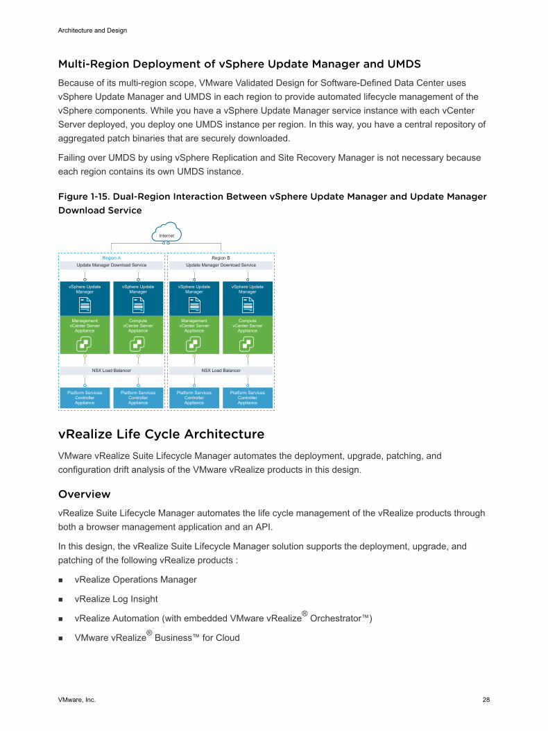
Multi-Region Deployment of vSphere Update Manager and UMDSBecause of its multi-region scope, VMware Validated Design for Software-Defined Data Center usesvSphere Update Manager and UMDS in each region to provide automated lifecycle management of thevSphere components. While you have a vSphere Update Manager service instance with each vCenterServer deployed, you deploy one UMDS instance per region. In this way, you have a central repository ofaggregated patch binaries that are securely downloaded.
Failing over UMDS by using vSphere Replication and Site Recovery Manager is not necessary becauseeach region contains its own UMDS instance.
Figure 1-15. Dual-Region Interaction Between vSphere Update Manager and Update ManagerDownload Service
Update Manager Download Service
NSX Load Balancer
Platform Services Controller Appliance
Platform Services Controller Appliance
vSphere UpdateManager
ManagementvCenter Server
Appliance
vSphere UpdateManager
ComputevCenter Server
Appliance
Internet
Region AUpdate Manager Download Service
NSX Load Balancer
Platform Services Controller Appliance
Platform Services Controller Appliance
vSphere UpdateManager
ManagementvCenter Server
Appliance
vSphere UpdateManager
ComputevCenter Server
Appliance
Region B
vRealize Life Cycle Architecture VMware vRealize Suite Lifecycle Manager automates the deployment, upgrade, patching, andconfiguration drift analysis of the VMware vRealize products in this design.
OverviewvRealize Suite Lifecycle Manager automates the life cycle management of the vRealize products throughboth a browser management application and an API.
In this design, the vRealize Suite Lifecycle Manager solution supports the deployment, upgrade, andpatching of the following vRealize products :
n vRealize Operations Manager
n vRealize Log Insight
n vRealize Automation (with embedded VMware vRealize® Orchestrator™)
n VMware vRealize® Business™ for Cloud
Architecture and Design
VMware, Inc. 28
DeploymentvRealize Suite Lifecycle Manager is a preconfigured appliance distributed in an Open Virtual Appliance(.ova) format. After the appliance deployment, you can access vRealize Suite Lifecycle Manager byusing both the browser application user interface and the API.
After you deploy vRealize Suite Lifecycle Manager, you register one or more vCenter Server instanceswith it.
Life Cycle Management FeaturesAn administrator can automate life cycle management operations for vRealize products. vRealize SuiteLifecycle Manager provides the following features for management of vRealize products:
n Manage a product install, patch, and upgrade repository.
n Deploy products using supported topologies.
n Patch and upgrade product deployments.
n Scale out product deployments.
n Manage and deploy Marketplace content across vRealize solutions.
n Support the import of existing product deployments.
n Baseline and report on a product configuration drift.
n Organize product deployments in logical environments.
ArchitecturevRealize Suite Lifecycle Manager contains the functional elements that collaborate to orchestrate the lifecycle management operations of the vRealize products in this validated design.
Similar to the vSphere Update Manager, vRealize Suite Lifecycle Manager can download product binariesfrom My VMware and content from the VMware Marketplace.
Architecture and Design
VMware, Inc. 29
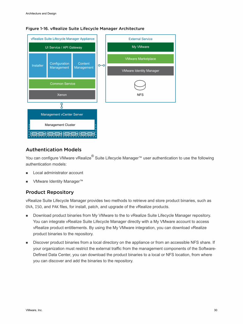
Figure 1-16. vRealize Suite Lifecycle Manager Architecture
ConfigurationManagementInstaller Content
Management
Management vCenter Server
Xenon NFS
Common Service
UI Service / API Gateway
vRealize Suite Lifecycle Manager Appliance External Service
My VMware
VMware Marketplace
VMware Identity Manager
Management Cluster
Authentication ModelsYou can configure VMware vRealize® Suite Lifecycle Manager™ user authentication to use the followingauthentication models:
n Local administrator account
n VMware Identity Manager™
Product RepositoryvRealize Suite Lifecycle Manager provides two methods to retrieve and store product binaries, such asOVA, ISO, and PAK files, for install, patch, and upgrade of the vRealize products.
n Download product binaries from My VMware to the to vRealize Suite Lifecycle Manager repository.You can integrate vRealize Suite Lifecycle Manager directly with a My VMware account to accessvRealize product entitlements. By using the My VMware integration, you can download vRealizeproduct binaries to the repository.
n Discover product binaries from a local directory on the appliance or from an accessible NFS share. Ifyour organization must restrict the external traffic from the management components of the Software-Defined Data Center, you can download the product binaries to a local or NFS location, from whereyou can discover and add the binaries to the repository.
Architecture and Design
VMware, Inc. 30

Marketplace IntegrationBy using vRealize Suite Lifecycle Manager, you can deploy additional vRealize Operations managementpacks, vRealize Log Insight content packs, and vRealize Automation blueprints and OVA files directly fromthe VMware Marketplace. The Marketplace integration requires a My VMware registration for theappliance.
BackupThe vRealize Suite Lifecycle Manager appliance is backed up by using traditional virtual machine backupsolutions that are compatible with VMware vSphere Storage APIs – Data Protection (VADP).
Multi-Region Deployment of vRealize Suite Lifecycle ManagerThe scope of this design can cover both a single region and multiple regions, and availability zones.
In a multi-region implementation, VMware Validated Design for Software-Defined Data Center implementsa vRealize Suite Lifecycle Manager setup in multiple regions by using the following configuration:
n A single vRealize Suite Lifecycle Manager appliance is replicated by vSphere Replication andrecovered by Site Recovery Manager. You can fail over the vRealize Suite Lifecycle Managerappliance across regions when there is a planned migration or disaster recovery event.
n The vRealize Suite Lifecycle Manager instance manages the deployment, upgrade, patching, andconfiguration drift analysis of the vRealize products across all regions.
In a multi-availability zone implementation, vRealize Suite Lifecycle Manager continues to provide lifecycle services for the vRealize product deployments in all regions of the SDDC. The vRealize SuiteLifecycle Manager virtual appliance resides in Availability Zone 1 in Region A. If this zone becomescompromised, the appliance instance is brought back online in Availability Zone 2.
Monitoring Architecture vRealize Operations Manager tracks and analyzes the operation of multiple data sources in the SDDC byusing specialized analytic algorithms. These algorithms help vRealize Operations Manager learn andpredict the behavior of every object it monitors. Users access this information by using views, reports, anddashboards.
DeploymentvRealize Operations Manager is available as a pre-configured virtual appliance in OVF. By using thevirtual appliance, you can easily create vRealize Operations Manager nodes with pre-defined identicalsizes.
You deploy the OVF file of the virtual appliance once for each node. After node deployment, you accessthe product to set up cluster nodes according to their role and log in to configure the installation.
Deployment ModelsYou can deploy vRealize Operations Manager as a virtual appliance in one of the following configurations:
n Standalone node
Architecture and Design
VMware, Inc. 31
n Cluster of one master and at least one data node, and optionally a group of remote collector nodes.
You can establish high availability by using an external load balancer.
The compute and storage resources of the vRealize Operations Manager instances can scale up asgrowth demands.
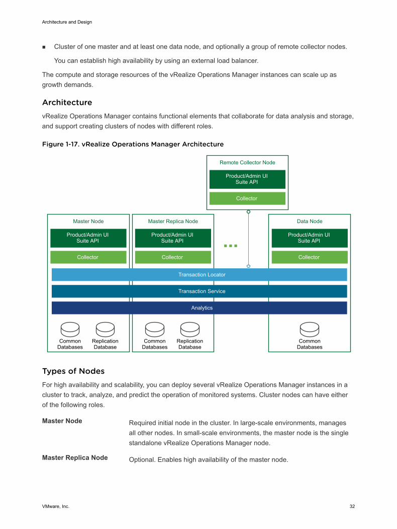
ArchitecturevRealize Operations Manager contains functional elements that collaborate for data analysis and storage,and support creating clusters of nodes with different roles.
Figure 1-17. vRealize Operations Manager Architecture
Remote Collector Node
Product/Admin UISuite API
Collector
Master Node
Product/Admin UISuite API
CommonDatabases
ReplicationDatabase
Collector
Data Node
Product/Admin UISuite API
CommonDatabases
Collector
Master Replica Node
Product/Admin UISuite API
CommonDatabases
ReplicationDatabase
Collector
Transaction Locator
Transaction Service
Analytics
Types of NodesFor high availability and scalability, you can deploy several vRealize Operations Manager instances in acluster to track, analyze, and predict the operation of monitored systems. Cluster nodes can have eitherof the following roles.
Master Node Required initial node in the cluster. In large-scale environments, managesall other nodes. In small-scale environments, the master node is the singlestandalone vRealize Operations Manager node.
Master Replica Node Optional. Enables high availability of the master node.
Architecture and Design
VMware, Inc. 32
Data Node Optional. Enables scale-out of vRealize Operations Manager in largerenvironments. Data nodes have adapters installed to perform collection andanalysis. Data nodes also host vRealize Operations Manager managementpacks.
Remote Collector Node Overcomes data collection issues across the enterprise network, such aslimited network performance. You can also use remote collector nodes tooffload data collection from the other types of nodes.
Remote collector nodes only gather statistics about inventory objects andforward collected data to the data nodes. Remote collector nodes do notstore data or perform analysis.
The master and master replica nodes are data nodes that have extended capabilities.
Types of Node Groups
Analytics Cluster Tracks, analyzes, and predicts the operation of monitored systems.Consists of a master node, data nodes, and optionally of a master replicanode.
Remote CollectorGroup
Because it consists of remote collector nodes, only collects diagnosticsdata without storage or analysis. A vRealize Operations Managerdeployment can contain several collector groups.
Use collector groups to achieve adapter resiliency in cases where thecollector experiences network interruption or becomes unavailable.
Application Functional Components The functional components of a vRealize Operations Manager instance interact with each other toanalyze diagnostics data from the data center and visualize the result in the Web user interface.
Architecture and Design
VMware, Inc. 33
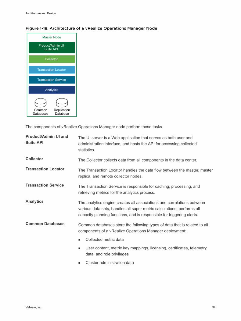
Figure 1-18. Architecture of a vRealize Operations Manager Node
Master Node
Product/Admin UISuite API
CommonDatabases
ReplicationDatabase
Collector
Transaction Locator
Transaction Service
Analytics
The components of vRealize Operations Manager node perform these tasks.
Product/Admin UI andSuite API
The UI server is a Web application that serves as both user andadministration interface, and hosts the API for accessing collectedstatistics.
Collector The Collector collects data from all components in the data center.
Transaction Locator The Transaction Locator handles the data flow between the master, masterreplica, and remote collector nodes.
Transaction Service The Transaction Service is responsible for caching, processing, andretrieving metrics for the analytics process.
Analytics The analytics engine creates all associations and correlations betweenvarious data sets, handles all super metric calculations, performs allcapacity planning functions, and is responsible for triggering alerts.
Common Databases Common databases store the following types of data that is related to allcomponents of a vRealize Operations Manager deployment:
n Collected metric data
n User content, metric key mappings, licensing, certificates, telemetrydata, and role privileges
n Cluster administration data
Architecture and Design
VMware, Inc. 34
n Alerts and alarms including the root cause, and object historicalproperties and versions
Replication Database The replication database stores all resources, such as metadata,relationships, collectors, adapters, collector groups, and relationshipsbetween them.
Authentication SourcesYou can configure vRealize Operations Manager user authentication to use one or more of the followingauthentication sources:
n VMware vCenter® Single Sign-On
n VMware Identity Manager
n OpenLDAP via LDAP
n Active Directory via LDAP
Management PacksManagement packs contain extensions and third-party integration software. They add dashboards, alertdefinitions, policies, reports, and other content to the inventory of vRealize Operations Manager. You canlearn more details about and download management packs from VMware Solutions Exchange.
BackupYou back up each vRealize Operations Manager node using traditional virtual machine backup solutionsthat are compatible with VMware vSphere Storage APIs – Data Protection (VADP).
Multi-Region vRealize Operations Manager DeploymentThe scope of this validated design can cover both multiple regions and availability zones.
VMware Validated Design for Software-Defined Data Center implements a large-scale vRealizeOperations Manager deployment across multiple regions by using the following configuration:
n Load-balanced analytics cluster that runs multiple nodes is protected by Site Recovery Manager tofail over across regions
n Multiple remote collector nodes that are assigned to a remote collector group in each region to handledata coming from management solutions
In a multi-availability zone implementation, which is a super-set of the multi-region design, vRealizeOperations Manager continues to provide monitoring of the solutions in all regions of the SDDC. Allcomponents of vRealize Operations Manager reside in Availability Zone 1 in Region A. If this zonebecomes compromised, all nodes are brought up in Availability Zone 2.
Architecture and Design
VMware, Inc. 35
Logging Architecture vRealize Log Insight provides real-time log management and log analysis with machine learning-basedintelligent grouping, high-performance searching, and troubleshooting across physical, virtual, and cloudenvironments.
OverviewvRealize Log Insight collects data from ESXi hosts using the syslog protocol. vRealize Log Insight has thefollowing capabilities:
n Connects to other VMware products, such as vCenter Server, to collect events, tasks, and alarmdata.
n Integrates with vRealize Operations Manager to send notification events and enable launch incontext.
n Functions as a collection and analysis point for any system that is capable of sending syslog data.
To collect additional logs, you can install an ingestion agent on Linux or Windows servers, or you can usethe preinstalled agent on certain VMware products. Using preinstalled agents is useful for customapplication logs and operating systems that do not natively support the syslog protocol, such as Windows.
DeploymentvRealize Log Insight is available as a preconfigured virtual appliance in OVF. By using the virtualappliance, you can easily create vRealize Log Insight nodes with predefined identical sizes.
You deploy the OVF file of the virtual appliance once for each node. After node deployment, you accessthe product to set up cluster nodes according to their role and log in to configure the installation.
Deployment ModelsYou can deploy vRealize Log Insight as a virtual appliance in one of the following configurations:
n Standalone node
n Cluster of one master and at least two worker nodes. You can establish high availability by using theintegrated load balancer (ILB).
The compute and storage resources of the vRealize Log Insight instances can scale-up as growthdemands.
ArchitectureThe architecture of vRealize Log Insight in the SDDC enables several channels for the collection of logmessages.
Architecture and Design
VMware, Inc. 36
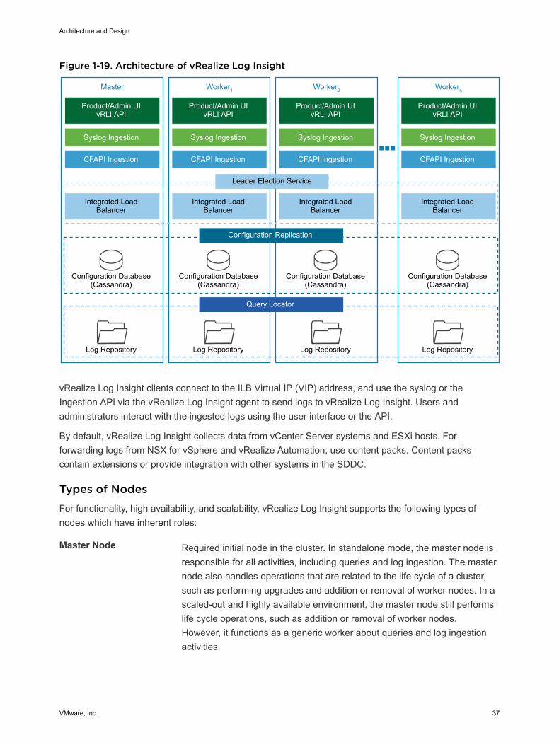
Figure 1-19. Architecture of vRealize Log Insight
Master
Product/Admin UIvRLI API
Integrated Load Balancer
Configuration Database(Cassandra)
Log Repository
Leader Election Service
Configuration Replication
Query Locator
Syslog Ingestion
CFAPI Ingestion
Worker1
Product/Admin UIvRLI API
Integrated Load Balancer
Configuration Database(Cassandra)
Log Repository
Syslog Ingestion
CFAPI Ingestion
Worker2
Product/Admin UIvRLI API
Integrated Load Balancer
Configuration Database(Cassandra)
Log Repository
Syslog Ingestion
CFAPI Ingestion
Workern
Product/Admin UIvRLI API
Integrated Load Balancer
Configuration Database(Cassandra)
Log Repository
Syslog Ingestion
CFAPI Ingestion
vRealize Log Insight clients connect to the ILB Virtual IP (VIP) address, and use the syslog or theIngestion API via the vRealize Log Insight agent to send logs to vRealize Log Insight. Users andadministrators interact with the ingested logs using the user interface or the API.
By default, vRealize Log Insight collects data from vCenter Server systems and ESXi hosts. Forforwarding logs from NSX for vSphere and vRealize Automation, use content packs. Content packscontain extensions or provide integration with other systems in the SDDC.
Types of NodesFor functionality, high availability, and scalability, vRealize Log Insight supports the following types ofnodes which have inherent roles:
Master Node Required initial node in the cluster. In standalone mode, the master node isresponsible for all activities, including queries and log ingestion. The masternode also handles operations that are related to the life cycle of a cluster,such as performing upgrades and addition or removal of worker nodes. In ascaled-out and highly available environment, the master node still performslife cycle operations, such as addition or removal of worker nodes.However, it functions as a generic worker about queries and log ingestionactivities.
Architecture and Design
VMware, Inc. 37
The master node stores logs locally. If the master node is down, the logsstored on it become unavailable.
Worker Node Optional. This component enables scale-out in larger environments. As youadd and configure more worker nodes in a vRealize Log Insight cluster forhigh availability (HA), queries and log ingestion activities are delegated toall available nodes. You must have at least two worker nodes to form acluster with the master node.
The worker node stores logs locally. If any of the worker nodes is down, thelogs on the worker become unavailable.
Integrated LoadBalancer (ILB)
In cluster mode, the ILB is the centralized entry point which ensures thatvRealize Log Insight accepts incoming ingestion traffic. As nodes areadded to the vRealize Log Insight instance to form a cluster, the ILB featuresimplifies the configuration for high availability. The ILB balances theincoming traffic fairly among the available vRealize Log Insight nodes.
The ILB runs on one of the cluster nodes at all times. In environments thatcontain several nodes, an election process determines the leader of thecluster. Periodically, the ILB performs a health check to determine whetherre-election is required. If the node that hosts the ILB Virtual IP (VIP)address stops responding, the VIP address is failed over to another node inthe cluster via an election process.
All queries against data are directed to the ILB. The ILB delegates queriesto a query master for the duration of the query. The query master queries allnodes, both master and worker nodes, for data and then sends theaggregated data back to the client.
Use the ILB for administrative activities unless you are performingadministrative activities on individual nodes. The Web user interface of theILB presents data from the master and from the worker nodes in a scaled-out cluster in a unified display(single pane of glass).
Application Functional ComponentsThe functional components of a vRealize Log Insight instance interact with each other to perform thefollowing operations:
n Analyze logging data that is ingested from the components of a data center
n Visualize the results in a Web browser, or support results query using API calls.
Architecture and Design
VMware, Inc. 38
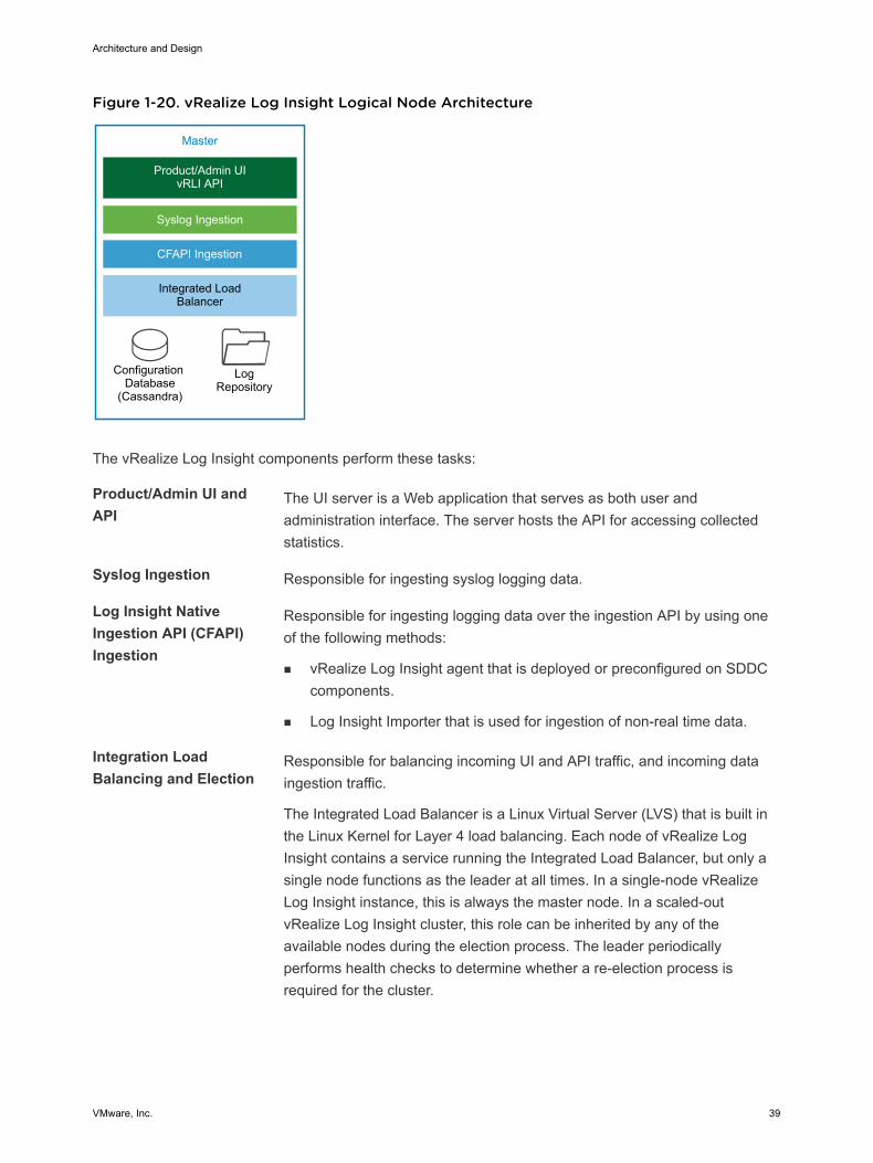
Figure 1-20. vRealize Log Insight Logical Node Architecture
Master
Product/Admin UIvRLI API
Integrated Load Balancer
Configuration Database
(Cassandra)
LogRepository
Syslog Ingestion
CFAPI Ingestion
The vRealize Log Insight components perform these tasks:
Product/Admin UI andAPI
The UI server is a Web application that serves as both user andadministration interface. The server hosts the API for accessing collectedstatistics.
Syslog Ingestion Responsible for ingesting syslog logging data.
Log Insight NativeIngestion API (CFAPI)Ingestion
Responsible for ingesting logging data over the ingestion API by using oneof the following methods:
n vRealize Log Insight agent that is deployed or preconfigured on SDDCcomponents.
n Log Insight Importer that is used for ingestion of non-real time data.
Integration LoadBalancing and Election
Responsible for balancing incoming UI and API traffic, and incoming dataingestion traffic.
The Integrated Load Balancer is a Linux Virtual Server (LVS) that is built inthe Linux Kernel for Layer 4 load balancing. Each node of vRealize LogInsight contains a service running the Integrated Load Balancer, but only asingle node functions as the leader at all times. In a single-node vRealizeLog Insight instance, this is always the master node. In a scaled-outvRealize Log Insight cluster, this role can be inherited by any of theavailable nodes during the election process. The leader periodicallyperforms health checks to determine whether a re-election process isrequired for the cluster.
Architecture and Design
VMware, Inc. 39
Configuration Database Stores configuration information about the vRealize Log Insight nodes andcluster. The information that is stored in the database is periodicallyreplicated to all available vRealize Log Insight nodes.
Log Repository Stores logging data that is ingested in vRealize Log Insight. The loggingrepository is local to each node and not replicated. If a node is offline orremoved, the logging data which is stored on that node becomesinaccessible. In environments where an ILB is configured, incoming loggingdata is evenly distributed across all available nodes.
When a query arrives from the ILB, the vRealize Log Insight node holdingthe ILB leader role delegates the query to any of the available nodes in thecluster.
Authentication ModelsYou can configure vRealize Log Insight user authentication to utilize one or more of the followingauthentication models:
n Microsoft Active Directory
n Local Accounts
n VMware Identity Manager
Content PacksContent packs help add valuable troubleshooting information to vRealize Log Insight. Content packsprovide structure and meaning to raw logging data that is collected from either a vRealize Log Insightagent, vRealize Log Insight Importer, or a syslog stream. They add vRealize Log Insight agentconfigurations, providing out-of-the-box parsing capabilities for standard logging directories and loggingformats, along with dashboards, extracted fields, alert definitions, query lists, and saved queries from thelogging data related to a specific product in vRealize Log Insight. You can install content packs fromContent Pack Marketplace in the vRealize Log Insight user interface. You can download content packsfrom the VMware Solutions Exchange at https://marketplace.vmware.com/.
Integration with vRealize Operations ManagerThe integration of vRealize Log Insight with vRealize Operations Manager provides data from multiplesources to a central place for monitoring the SDDC. The integration has the following advantages:
n vRealize Log Insight sends notification events to vRealize Operations Manager.
n vRealize Operations Manager can provide the inventory map of any vSphere object to vRealize LogInsight. In this way, you can view log messages from vRealize Log Insight in the vRealize OperationsManager Web user interface, taking you either directly to the object itself or to the location of theobject within the environment.
n Access to the vRealize Log Insight user interface is embedded in the vRealize Operations Manageruser interface .
Architecture and Design
VMware, Inc. 40
ArchivingvRealize Log Insight supports data archiving on an NFS shared storage that the vRealize Log Insightnodes can access. However, vRealize Log Insight does not manage the NFS mount used for archivingpurposes. vRealize Log Insight also does not perform cleanup of the archival files.
The NFS mount for archiving can run out of free space or become unavailable for a period of time greaterthan the retention period of the virtual appliance. In that case, vRealize Log Insight stops ingesting newdata until the NFS mount has enough free space or becomes available, or until archiving is disabled. Ifarchiving is enabled, system notifications from vRealize Log Insight sends you an email when the NFSmount is about to run out of space or is unavailable.
BackupYou back up each vRealize Log Insight cluster using traditional virtual machine backup solutions that arecompatible with VMware vSphere Storage APIs – Data Protection (VADP).
Multi-Region vRealize Log Insight DeploymentThe scope of this validated design can cover both multiple regions and availability zones.
In a multi-region implementation, vRealize Log Insight provides a separate logging infrastructure in eachregion of the SDDC. Using vRealize Log Insight across multiple regions requires the followingconfiguration:
n Cluster in each region.
n Event forwarding to other vRealize Log Insight deployments across regions in the SDDC.
In a multi-availabilty zone implementation, which is a sub-set of the multi-region design, vRealize Loginsight continues to provide a logging infrastructure in all regions of the SDDC. All components of thevRealize Log Insight cluster reside in Availability Zone 1 within Region A. If this zone becomescompromised, all nodes are brought up in the Availability Zone 2.
Failover by using vSphere Replication or disaster recovery by using Site Recovery Manager is notnecessary. The event forwarding feature adds tags to log messages that identify the source region. Eventfiltering prevents looping messages between the regions.
Architecture and Design
VMware, Inc. 41
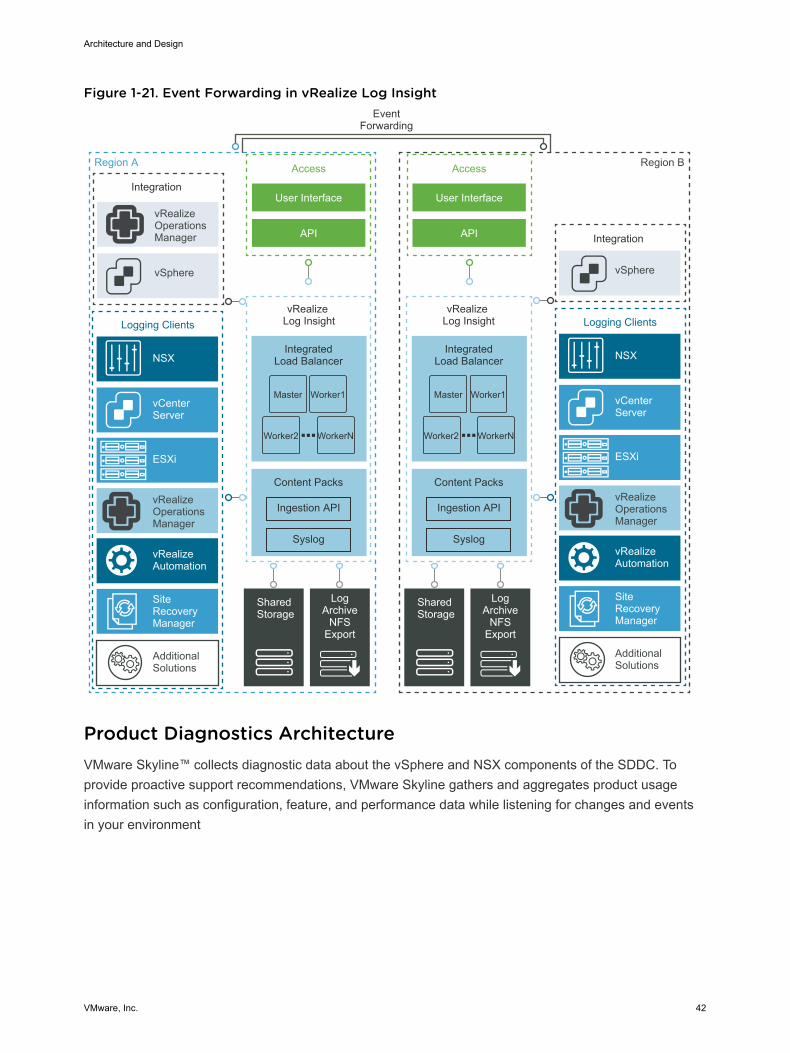
Figure 1-21. Event Forwarding in vRealize Log Insight
Region A
EventForwarding
Integration
IntegratedLoad Balancer
vSphere
Access
User Interface
API
vRealizeOperationsManager
Content Packs
Syslog
Ingestion API
IntegratedLoad Balancer
Content Packs
Syslog
Ingestion API
Shared Storage
LogArchive
NFSExport
Region B
vRealize Log Insight
vRealize Log Insight
Integration
vSphere
Access
User Interface
API
vRealizeOperationsManager
Logging Clients
vCenter Server
ESXi
NSX
vRealizeAutomation
AdditionalSolutions
Shared Storage
LogArchive
NFSExport
Master Worker1
Worker2 WorkerN
Master Worker1
Worker2 WorkerN
SiteRecoveryManager
vRealizeOperationsManager
Logging Clients
vCenter Server
ESXi
NSX
vRealizeAutomation
AdditionalSolutions
SiteRecoveryManager
Product Diagnostics Architecture VMware Skyline™ collects diagnostic data about the vSphere and NSX components of the SDDC. Toprovide proactive support recommendations, VMware Skyline gathers and aggregates product usageinformation such as configuration, feature, and performance data while listening for changes and eventsin your environment
Architecture and Design
VMware, Inc. 42
OverviewVMware Skyline implements proactive support for VMware SDDC products. VMware Skyline usesautomation to securely collect data and perform environment-specific analysis on configuration, feature,and performance data against best practices, VMware Knowledge Base articles, and Security Advisories.As a result, VMware can provide proactive, predictive, and prescriptive recommendations for improvingthe stability and reliability of the environment. In addition, VMware can resolve reactive support issuesfaster.
To use the proactive support capabilities of VMware Skyline, you must have an active Production Supportor Premier Services contract.
Note Product usage data might include customer identifiable information, such as ESXi host names, IPaddresses, license keys, customer IDs, or entitlement account numbers. For information about dataprivacy and security, see VMware Skyline FAQ .
Customer Experience Improvement ProgramCollection of product usage data by the VMware Skyline Collector™ instances is subject to acceptance inVMware’s Customer Experience Improvement Program (CEIP). The VMware Customer ExperienceImprovement Program (CEIP) provides information that helps VMware improve products and services, fixproblems, and advise you how best to deploy and use VMware products. See the CEIP home page.
VMware Skyline CollectorA Skyline Collector instance is a Java-based application that is available as a pre-configured virtualappliance in OVA format. A Skyline Collector instance collects product usage data from SDDC endpoints.Skyline Collector automatically and securely collects product usage data from compatible SDDCendpoints. The VMware Skyline Collector also listens for certain changes and events, and sends them tothe rules engine of VMware Skyline that runs in the cloud. To analyze inbound product information, therules engine uses a library of support intelligence, product knowledge, and logic. After the analysis iscomplete, you can view your proactive findings and recommendations in VMware Skyline Advisor.
The Skyline Collector UI is a VMware Clarity and Angular JavaScript application that is hosted on Nginx.You use the Skyline Collector UI to register endpoints for collection of product usage data and to managethe system status.
Before you start using a Skyline Collector instance, you must create an organization on VMware CloudServices, associate it with your customer entitlement account in My VMware, and generate a registrationtoken. When you log in to the collector for the first time, you connect the collector to your VMware CloudServices organization. Then, the level of service that you receive is determined according to the level ofentitlement that you have.
Architecture and Design
VMware, Inc. 43
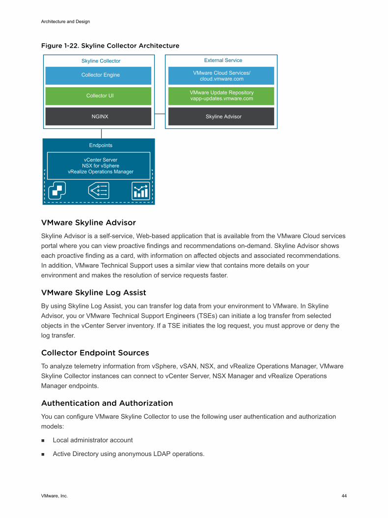
Figure 1-22. Skyline Collector Architecture
Collector Engine
Collector UI
NGINX
Skyline Collector
VMware Cloud Services/cloud.vmware.com
VMware Update Repositoryvapp-updates.vmware.com
External Service
Skyline Advisor
Endpoints
vCenter ServerNSX for vSphere
vRealize Operations Manager
VMware Skyline AdvisorSkyline Advisor is a self-service, Web-based application that is available from the VMware Cloud servicesportal where you can view proactive findings and recommendations on-demand. Skyline Advisor showseach proactive finding as a card, with information on affected objects and associated recommendations.In addition, VMware Technical Support uses a similar view that contains more details on yourenvironment and makes the resolution of service requests faster.
VMware Skyline Log AssistBy using Skyline Log Assist, you can transfer log data from your environment to VMware. In SkylineAdvisor, you or VMware Technical Support Engineers (TSEs) can initiate a log transfer from selectedobjects in the vCenter Server inventory. If a TSE initiates the log request, you must approve or deny thelog transfer.
Collector Endpoint SourcesTo analyze telemetry information from vSphere, vSAN, NSX, and vRealize Operations Manager, VMwareSkyline Collector instances can connect to vCenter Server, NSX Manager and vRealize OperationsManager endpoints.
Authentication and AuthorizationYou can configure VMware Skyline Collector to use the following user authentication and authorizationmodels:
n Local administrator account
n Active Directory using anonymous LDAP operations.
Architecture and Design
VMware, Inc. 44
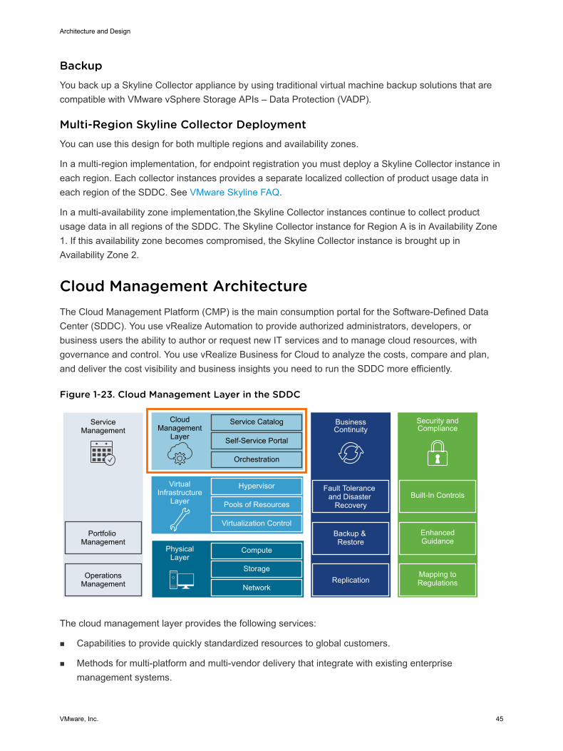
BackupYou back up a Skyline Collector appliance by using traditional virtual machine backup solutions that arecompatible with VMware vSphere Storage APIs – Data Protection (VADP).
Multi-Region Skyline Collector DeploymentYou can use this design for both multiple regions and availability zones.
In a multi-region implementation, for endpoint registration you must deploy a Skyline Collector instance ineach region. Each collector instances provides a separate localized collection of product usage data ineach region of the SDDC. See VMware Skyline FAQ.
In a multi-availability zone implementation,the Skyline Collector instances continue to collect productusage data in all regions of the SDDC. The Skyline Collector instance for Region A is in Availability Zone1. If this availability zone becomes compromised, the Skyline Collector instance is brought up inAvailability Zone 2.
Cloud Management Architecture The Cloud Management Platform (CMP) is the main consumption portal for the Software-Defined DataCenter (SDDC). You use vRealize Automation to provide authorized administrators, developers, orbusiness users the ability to author or request new IT services and to manage cloud resources, withgovernance and control. You use vRealize Business for Cloud to analyze the costs, compare and plan,and deliver the cost visibility and business insights you need to run the SDDC more efficiently.
Figure 1-23. Cloud Management Layer in the SDDC
ServiceManagement
Portfolio Management
OperationsManagement
CloudManagement
Layer
Service Catalog
Self-Service Portal
Orchestration
BusinessContinuity
Fault Tolerance and Disaster
Recovery
Backup & Restore
Hypervisor
Pools of Resources
Virtualization Control
VirtualInfrastructure
Layer
Compute
Storage
Network
PhysicalLayer
Replication
Security and Compliance
Mapping to Regulations
Enhanced Guidance
Built-In Controls
The cloud management layer provides the following services:
n Capabilities to provide quickly standardized resources to global customers.
n Methods for multi-platform and multi-vendor delivery that integrate with existing enterprisemanagement systems.
Architecture and Design
VMware, Inc. 45
n Central governance for cloud services that is user-centric and is aware of the business requirements.
n Extensible architecture
vRealize Automation Architecture vRealize Automation provides a secure portal where authorized administrators, developers, or businessusers can request new IT services and manage specific cloud and IT resources, while ensuringcompliance with predefined business policies for governance and control. Requests for IT services,including infrastructure, applications, and many others, are processed through a common service catalogto provide a consistent user experience despite underlying heterogenous infrastructure.
DeploymentvRealize Automation consists of a preconfigured appliance delivered in an Open Virtual Appliance (.ova)format and vRealize Automation Infrastructure as a Service (IaaS) components deployed on one or moreMicrosoft Windows Server virtual machines.
You can automate the deployment of vRealize Automation by using vRealize Suite Lifecycle Manager oryou can manually deploy the vRealize Automation appliance, and then you complete the installation usinga browser-based appliance configuration and IaaS server component installation.
vRealize Automation ArchitecturevRealize Automation provides self-service provisioning, IT services delivery, and life cycle management ofcloud services across a many multi-vendor cloud platforms using a flexible and distributed architecture.The two functional elements of the architecture are the vRealize Automation appliance and the IaaScomponents.
Architecture and Design
VMware, Inc. 46
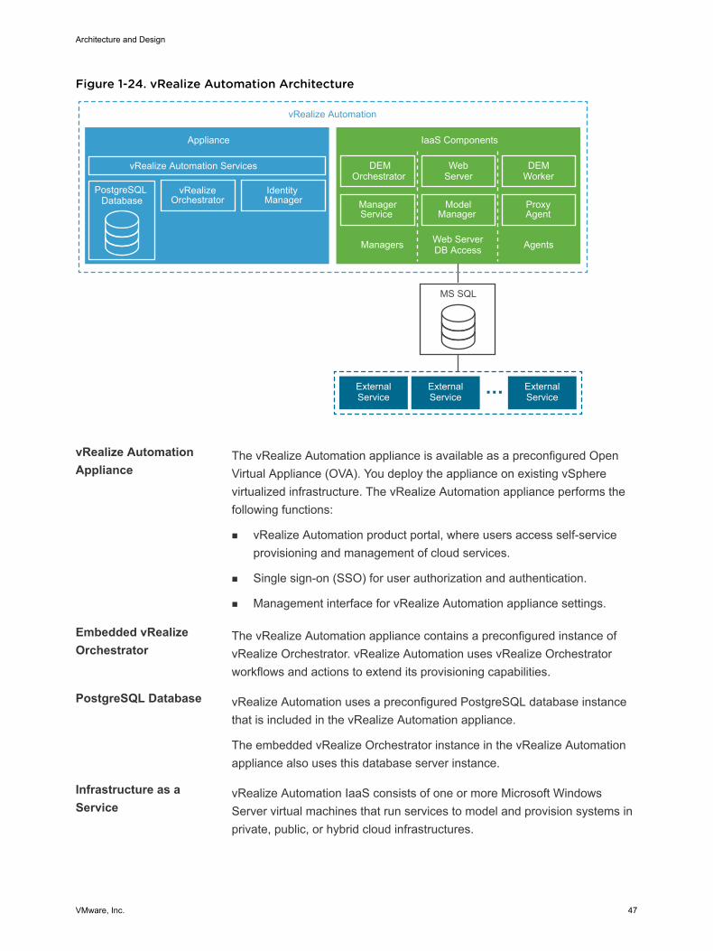
Figure 1-24. vRealize Automation Architecture
ModelManager
ProxyAgent
vRealize Automation
Appliance
vRealize Automation Services
PostgreSQL Database
vRealizeOrchestrator
Identity Manager
IaaS Components
MS SQL
ExternalService
ExternalService
ExternalService
DEMOrchestrator
WebServer
DEMWorker
ManagerService
Managers Web ServerDB Access Agents
vRealize AutomationAppliance
The vRealize Automation appliance is available as a preconfigured OpenVirtual Appliance (OVA). You deploy the appliance on existing vSpherevirtualized infrastructure. The vRealize Automation appliance performs thefollowing functions:
n vRealize Automation product portal, where users access self-serviceprovisioning and management of cloud services.
n Single sign-on (SSO) for user authorization and authentication.
n Management interface for vRealize Automation appliance settings.
Embedded vRealizeOrchestrator
The vRealize Automation appliance contains a preconfigured instance ofvRealize Orchestrator. vRealize Automation uses vRealize Orchestratorworkflows and actions to extend its provisioning capabilities.
PostgreSQL Database vRealize Automation uses a preconfigured PostgreSQL database instancethat is included in the vRealize Automation appliance.
The embedded vRealize Orchestrator instance in the vRealize Automationappliance also uses this database server instance.
Infrastructure as aService
vRealize Automation IaaS consists of one or more Microsoft WindowsServer virtual machines that run services to model and provision systems inprivate, public, or hybrid cloud infrastructures.
Architecture and Design
VMware, Inc. 47
Model Manager vRealize Automation uses models to facilitate integration with externalsystems and databases. The models implement business logic used by theDistributed Execution Manager (DEM).
The Model Manager provides services and utilities for persisting,versioning, securing, and distributing model elements. The Model Manageris hosted on one of the IaaS Web Servers and communicates with DEMs,the Microsoft SQL Server database, and the product browser-based userinterface.
Web Server The IaaS Web Server provides infrastructure administration and serviceauthoring to the vRealize Automation product browser-based userinterface. The web server component communicates with the ManagerService, which provides updates from the Distributed Execution Manager,Microsoft SQL Server database, and proxy agents.
Manager Service The IaaS Manager Service coordinates the communication between IaaSDEMs, the Microsoft SQL Server database, agents, and SMTP. TheManager Service communicates with the Web Server through the ModelManager, and must be run under a domain account with administratorprivileges on all vRealize Automation IaaS component instances.
Microsoft SQL ServerDatabase
vRealize Automation IaaS uses a Microsoft SQL Server database tomaintain information about the machines it manages, plus its own elementsand policies.
Distributed ExecutionManager Orchestrator
The IaaS Distributed Execution Manager (DEM) component runs thebusiness logic of custom models, interacting with the IaaS SQL Serverdatabase, and with external databases and systems, as required. A DEMOrchestrator is responsible for monitoring DEM Worker instances, pre-processing workflows for execution, and scheduling workflows.
Distributed ExecutionManager Worker
The IaaS DEM Worker performs provisioning and de-provisioning tasksinitiated by the vRealize Automation portal. DEM Workers alsocommunicate with specific infrastructure endpoints.
Proxy Agents vRealize Automation IaaS uses proxy agents to integrate with externalsystems and to manage information among vRealize Automationcomponents. For example, a IaaS Proxy Agent for vSphere sendscommands to and collects data from an ESXi host about the virtualmachines that you provisioned from vRealize Automation.
Identity Manager An embedded instance of VMware Identity Manager in each vRealizeAutomation appliance provides the main identity provider for vRealizeAutomation.
Architecture and Design
VMware, Inc. 48
Identity Manager manages user authentication, roles, permissions, andoverall access to vRealize Automation using federated identity brokering.The following authentication methods are supported in vRealize Automationusing Identity Manager:
n User name-password providing single-factor password authenticationwith basic Active Directory configuration or for local users
n Kerberos
n Smart Card / Certificate
n RSA SecurID
n RADIUS
n RSA Adaptive Authentication
n SAML Authentication
Deployment ModelYou can deploy vRealize Automation in one of the following deployment configurations:
n Small deployment
n 1 vRealize Automation appliance, potentially behind a load balancer
n 1 vRealize Automation IaaS virtual machine
n Microsoft SQL Server Database
The small deployment serves as a starting point for a vRealize Automation deployment that enablesyou to scale in a supported manner to a medium or large deployment.
n Medium deployment
n 3 vRealize Automation appliances behind a load balancer
n 2 vRealize Automation IaaS Web Server/Manager Service virtual machines behind a loadbalancer
n 2 vRealize Automation IaaS DEM Worker virtual machines
n 2 vRealize Automation IaaS Proxy Agent virtual machines
n Microsoft SQL Server Database
n Large deployment
n 3 vRealize Automation appliances behind a load balancer
n 2 vRealize Automation IaaS Web Server virtual machines behind a load balancer
n 2 vRealize Automation IaaS Manager Service virtual machines behind a load balancer
n 2 vRealize Automation IaaS DEM Worker virtual machines
Architecture and Design
VMware, Inc. 49
n 2 vRealize Automation IaaS Proxy Agent virtual machines
n Microsoft SQL Server Database
To address future growth of tenant workloads beyond 10,000 virtual machines without more operationaloverhead, this design implements a large deployment of vRealize Automation.
Multi-Region vRealize Automation DeploymentThe scope of this design can cover both multiple regions and availability zones.
The scope of this design includes vRealize Automation in a large-scale distributed deployment designedfor a complete and highly available cloud management solution that includes:
Table 1-5. vRealize Automation Components that Are Failed Over
Failed Over
3 vRealize Automation appliances behind a load balancer X
2 vRealize Automation IaaS Web Server virtual machinesbehind a load balancer
X
2 vRealize Automation IaaS Manager Service (including DEMOrchestrator) virtual machines behind a load balancer
X
2 vRealize Automation IaaS DEM Worker virtual machines X
2 vRealize Automation IaaS Proxy Agent (vSphere) virtualmachines
Microsoft SQL Server Database X
In a multi-availability zone implementation, which is a super-set of the multi-region design, vRealizeAutomation continues to provide provisioning of tenant workloads in all regions of the SDDC. Allcomponents of the vRealize Automation reside in Availability Zone 1 in Region A. If this zone becomescompromised, all nodes are brought up in Availability Zone 2.
vRealize Business for Cloud Architecture vRealize Business for Cloud automates cloud costing, consumption analysis, and comparison, deliveringthe insight you need to deploy and manage cloud environments efficiently.
Use vRealize Business for Cloud to track and manage the costs of private and public cloud resourcesfrom a single dashboard. The dashboard offers a comprehensive way to see, plan, and manage yourcloud costs.
You can integrate vRealize Business for Cloud with vRealize Automation. The architecture illustrates themain components of vRealize Business for Cloud, the server, FactsRepo inventory service, datatransformation service, data collection services, and reference database.
Architecture and Design
VMware, Inc. 50
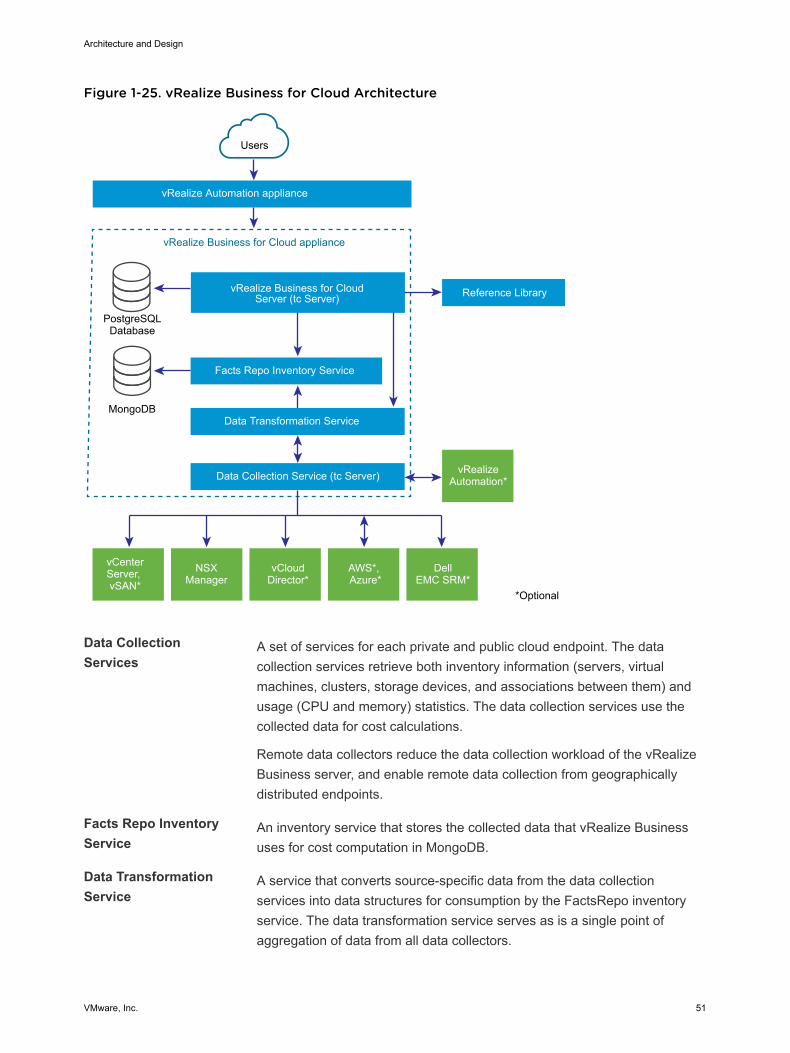
Figure 1-25. vRealize Business for Cloud Architecture
vRealize Business for Cloud appliance
vRealize Automation appliance
Users
vRealize Business for CloudServer (tc Server)
Facts Repo Inventory Service
PostgreSQLDatabase
Reference Library
MongoDBData Transformation Service
Data Collection Service (tc Server)
*Optional
vCenterServer, vSAN*
NSXManager
vCloudDirector*
AWS*, Azure*
Dell EMC SRM*
vRealizeAutomation*
Data CollectionServices
A set of services for each private and public cloud endpoint. The datacollection services retrieve both inventory information (servers, virtualmachines, clusters, storage devices, and associations between them) andusage (CPU and memory) statistics. The data collection services use thecollected data for cost calculations.
Remote data collectors reduce the data collection workload of the vRealizeBusiness server, and enable remote data collection from geographicallydistributed endpoints.
Facts Repo InventoryService
An inventory service that stores the collected data that vRealize Businessuses for cost computation in MongoDB.
Data TransformationService
A service that converts source-specific data from the data collectionservices into data structures for consumption by the FactsRepo inventoryservice. The data transformation service serves as is a single point ofaggregation of data from all data collectors.
Architecture and Design
VMware, Inc. 51
vRealize Business forCloud Server
A browser-based application that runs on Pivotal tc Server. vRealizeBusiness for Cloud has multiple data collection services that runperiodically, collecting inventory information and statistics, which are storedin a PostgreSQL database. Data that is collected from the data collectionservices is used for cost calculations.
Reference Database A database that is responsible for providing default costs for each of thesupported cost drivers. The reference database is updated automatically ormanually. You can download the latest data set and import it to vRealizeBusiness. The new values affect cost calculation. The reference data useddepends on the currency you select at the time of installation.
Important You cannot change the currency configuration after you deployvRealize Business for Cloud.
CommunicationBetween Server andReference Database
The reference database is a compressed and encrypted file, which you candownload and install manually or update automatically. You can update themost current version of reference database.
Other Sources ofInformation
Optionally, vRealize Business for Cloud integrates with various products, sothat you can use the information directly from the integration if installed andconfigured. These products include vRealize Automation, NSX for vSphere,vCloud Director, Amazon Web Services, Microsoft Azure, and EMC StorageResource Manager.
Operational ModelvRealize Business for Cloud continuously collects data from external sources, and periodically updatesthe Facts Repo inventory service. You can view the collected data by using the vRealize Business forCloud dashboard or generate a report. Data synchronization and updates occur at regular intervals. Youcan also manually trigger the data collection process when inventory changes occur, for example, inresponse to the initialization of the system, or after addition of a cloud account.
BackupYou back up each vRealize Business Cloud appliance by using traditional virtual machine backupsolutions that are compatible with VMware vSphere Storage APIs – Data Protection (VADP).
Multi-Region vRealize Business for Cloud DeploymentThe scope of this validated design can cover both multiple regions and availability zones.
VMware Validated Design for Software-Defined Data Center implements a vRealize Business for Clouddeployment across multiple regions by using the following configuration:
n To support its availability in vRealize Automation, a vRealize Business for Cloud server instance isprotected by Site Recovery Manager to fail over across regions.
Architecture and Design
VMware, Inc. 52
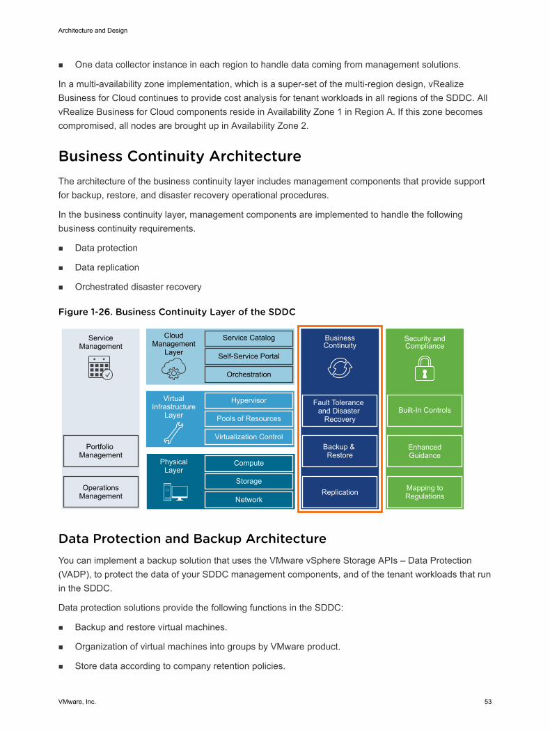
n One data collector instance in each region to handle data coming from management solutions.
In a multi-availability zone implementation, which is a super-set of the multi-region design, vRealizeBusiness for Cloud continues to provide cost analysis for tenant workloads in all regions of the SDDC. AllvRealize Business for Cloud components reside in Availability Zone 1 in Region A. If this zone becomescompromised, all nodes are brought up in Availability Zone 2.
Business Continuity Architecture The architecture of the business continuity layer includes management components that provide supportfor backup, restore, and disaster recovery operational procedures.
In the business continuity layer, management components are implemented to handle the followingbusiness continuity requirements.
n Data protection
n Data replication
n Orchestrated disaster recovery
Figure 1-26. Business Continuity Layer of the SDDC
ServiceManagement
Portfolio Management
OperationsManagement
CloudManagement
Layer
Service Catalog
Self-Service Portal
Orchestration
BusinessContinuity
Fault Tolerance and Disaster
Recovery
Backup & Restore
Hypervisor
Pools of Resources
Virtualization Control
VirtualInfrastructure
Layer
Compute
Storage
Network
PhysicalLayer
Replication
Security and Compliance
Mapping to Regulations
Enhanced Guidance
Built-In Controls
Data Protection and Backup Architecture You can implement a backup solution that uses the VMware vSphere Storage APIs – Data Protection(VADP), to protect the data of your SDDC management components, and of the tenant workloads that runin the SDDC.
Data protection solutions provide the following functions in the SDDC:
n Backup and restore virtual machines.
n Organization of virtual machines into groups by VMware product.
n Store data according to company retention policies.
Architecture and Design
VMware, Inc. 53
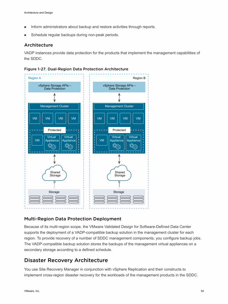
n Inform administrators about backup and restore activities through reports.
n Schedule regular backups during non-peak periods.
ArchitectureVADP instances provide data protection for the products that implement the management capabilities ofthe SDDC.
Figure 1-27. Dual-Region Data Protection Architecture
VMVMVMVM
VMVirtual
ApplianceVirtual
Appliance
VMVMVMVM
VMVirtual
ApplianceVirtual
Appliance
vSphere Storage APIs –Data Protection
Management Cluster
Storage
Region A Region B
Protected
SharedStorage
vSphere Storage APIs –Data Protection
Management Cluster
Storage
Protected
SharedStorage
Multi-Region Data Protection DeploymentBecause of its multi-region scope, the VMware Validated Design for Software-Defined Data Centersupports the deployment of a VADP-compatible backup solution in the management cluster for eachregion. To provide recovery of a number of SDDC management components, you configure backup jobs.The VADP-compatible backup solution stores the backups of the management virtual appliances on asecondary storage according to a defined schedule.
Disaster Recovery ArchitectureYou use Site Recovery Manager in conjunction with vSphere Replication and their constructs toimplement cross-region disaster recovery for the workloads of the management products in the SDDC.
Architecture and Design
VMware, Inc. 54
ArchitectureDisaster recovery that is based on Site Recovery Manager has the following main elements:
Dual-regionconfiguration
All protected virtual machines are initially located in Region A which isconsidered as the protected region, and are recovered in Region B which isconsidered as the recovery region. In a typical Site RecoveryManager installation, the protected region provides business-critical datacenter services. The recovery region is an alternative infrastructure set towhich Site Recovery Manager can relocate these services.
Replication of virtualmachine data
n Array-based replication. When you use array-based replication, one ormore storage arrays at the protected region replicate data to peerarrays at the recovery region. To use array-based replication with SiteRecovery Manager, you must configure replication first on the storagearray and install a storage specific adapter before you canconfigure Site Recovery Manager to use it.
n vSphere Replication. You configure vSphere Replication on virtualmachines independently of Site Recovery Manager. Replication doesnot occur at the storage array level. The replication source and targetstorage can be any storage device.
You can configure vSphere Replication to use the multiple-point-in-timesnapshot feature enabling more flexibility for data recovery of protectedvirtual machines on the recovery region.
Protection groups A protection group is a group of virtual machines that fail over together atthe recovery region during test and recovery. Each protection groupprotects one datastore group, and each datastore group can containmultiple datastores. However, you cannot create protection groups thatcombine virtual machines protected by array-based replication and vSphereReplication.
Recovery plans A recovery plan specifies how Site Recovery Manager recovers the virtualmachines in the protection groups. You can include a combination of array-based replication protection groups and vSphere Replication protectiongroups in the same recovery plan.
Architecture and Design
VMware, Inc. 55
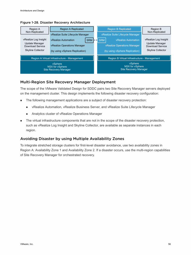
Figure 1-28. Disaster Recovery Architecture
Region A Non-Replicated
vRealize Log InsightUpdate Manager Download ServiceSkyline Collector
Region A Virtual Infrastructure - Management
vSphere NSX for vSphere
Site Recovery Manager
Region B Non-Replicated
Region B Replicated
vRealize Suite Lifecycle Manager
vRealize Automation
vRealize Operations Manager
(by using vSphere Replication)
SRM
Region A Replicated
SRM
vRealize Suite Lifecycle Manager
vRealize Automation
vRealize Operations Manager
(by using vSphere Replication)
Region B Virtual Infrastructure - Management
vSphereNSX for vSphere
Site Recovery Manager
vRealize Log InsightUpdate Manager Download ServiceSkyline Collector
Multi-Region Site Recovery Manager DeploymentThe scope of the VMware Validated Design for SDDC pairs two Site Recovery Manager servers deployedon the management cluster. This design implements the following disaster recovery configuration:
n The following management applications are a subject of disaster recovery protection:
n vRealize Automation, vRealize Business Server, and vRealize Suite Lifecycle Manager
n Analytics cluster of vRealize Operations Manager
n The virtual infrastructure components that are not in the scope of the disaster recovery protection,such as vRealize Log Insight and Skyline Collector, are available as separate instances in eachregion.
Avoiding Disaster by using Multiple Availability ZonesTo integrate stretched storage clusters for first-level disaster avoidance, use two availability zones inRegion A: Availability Zone 1 and Availability Zone 2. If a disaster occurs, use the multi-region capabilitiesof Site Recovery Manager for orchestrated recovery.
Architecture and Design
VMware, Inc. 56
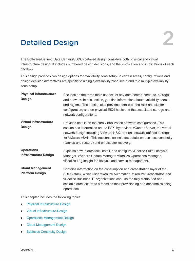
Detailed Design 2The Software-Defined Data Center (SDDC) detailed design considers both physical and virtualinfrastructure design. It includes numbered design decisions, and the justification and implications of eachdecision.
This design provides two design options for availability zone setup. In certain areas, configurations anddesign decision alternatives are specific to a single availability zone setup and to a multiple availabilityzone setup.
Physical InfrastructureDesign
Focuses on the three main aspects of any data center: compute, storage,and network. In this section, you find information about availability zonesand regions. The section also provides details on the rack and clusterconfiguration, and on physical ESXi hosts and the associated storage andnetwork configurations.
Virtual InfrastructureDesign
Provides details on the core virtualization software configuration. Thissection has information on the ESXi hypervisor, vCenter Server, the virtualnetwork design including VMware NSX, and on software-defined storagefor VMware vSAN. This section also includes details on business continuity(backup and restore) and on disaster recovery.
OperationsInfrastructure Design
Explains how to architect, install, and configure vRealize Suite LifecycleManager, vSphere Update Manager, vRealize Operations Manager,vRealize Log Insight for lifecycle and service management.
Cloud ManagementPlatform Design
Contains information on the consumption and orchestration layer of theSDDC stack, which uses vRealize Automation, vRealize Orchestrator, andvRealize Business. IT organizations can use the fully distributed andscalable architecture to streamline their provisioning and decommissioningoperations.
This chapter includes the following topics:
n Physical Infrastructure Design
n Virtual Infrastructure Design
n Operations Management Design
n Cloud Management Design
n Business Continuity Design
VMware, Inc. 57
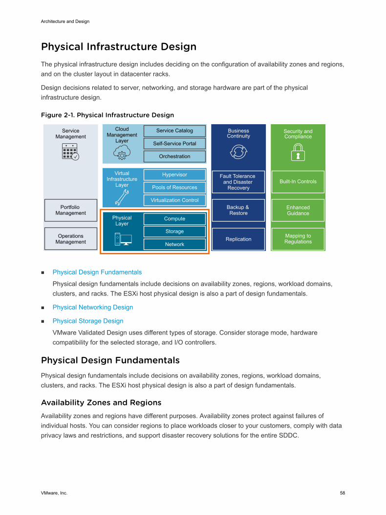
Physical Infrastructure Design The physical infrastructure design includes deciding on the configuration of availability zones and regions,and on the cluster layout in datacenter racks.
Design decisions related to server, networking, and storage hardware are part of the physicalinfrastructure design.
Figure 2-1. Physical Infrastructure Design
ServiceManagement
Portfolio Management
OperationsManagement
CloudManagement
Layer
Service Catalog
Self-Service Portal
Orchestration
BusinessContinuity
Fault Tolerance and Disaster
Recovery
Backup & Restore
Hypervisor
Pools of Resources
Virtualization Control
VirtualInfrastructure
Layer
Compute
Storage
Network
PhysicalLayer
Replication
Security and Compliance
Mapping to Regulations
Enhanced Guidance
Built-In Controls
n Physical Design Fundamentals
Physical design fundamentals include decisions on availability zones, regions, workload domains,clusters, and racks. The ESXi host physical design is also a part of design fundamentals.
n Physical Networking Design
n Physical Storage Design
VMware Validated Design uses different types of storage. Consider storage mode, hardwarecompatibility for the selected storage, and I/O controllers.
Physical Design Fundamentals Physical design fundamentals include decisions on availability zones, regions, workload domains,clusters, and racks. The ESXi host physical design is also a part of design fundamentals.
Availability Zones and Regions Availability zones and regions have different purposes. Availability zones protect against failures ofindividual hosts. You can consider regions to place workloads closer to your customers, comply with dataprivacy laws and restrictions, and support disaster recovery solutions for the entire SDDC.
Architecture and Design
VMware, Inc. 58
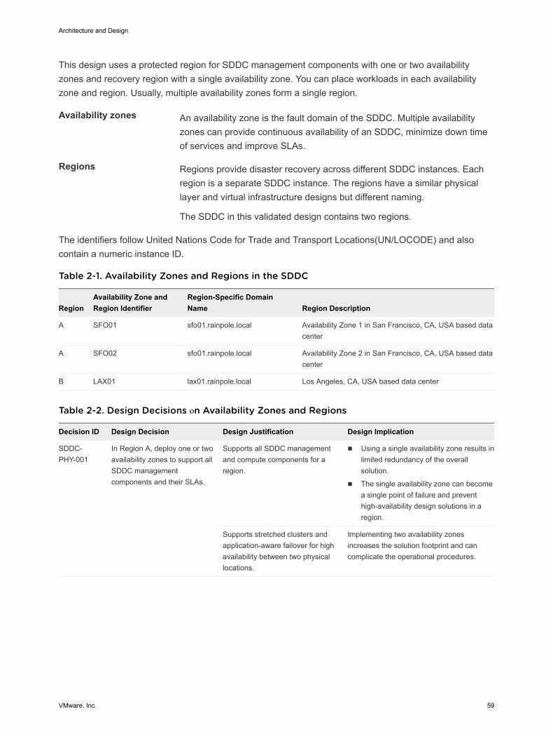
This design uses a protected region for SDDC management components with one or two availabilityzones and recovery region with a single availability zone. You can place workloads in each availabilityzone and region. Usually, multiple availability zones form a single region.
Availability zones An availability zone is the fault domain of the SDDC. Multiple availabilityzones can provide continuous availability of an SDDC, minimize down timeof services and improve SLAs.
Regions Regions provide disaster recovery across different SDDC instances. Eachregion is a separate SDDC instance. The regions have a similar physicallayer and virtual infrastructure designs but different naming.
The SDDC in this validated design contains two regions.
The identifiers follow United Nations Code for Trade and Transport Locations(UN/LOCODE) and alsocontain a numeric instance ID.
Table 2-1. Availability Zones and Regions in the SDDC
RegionAvailability Zone andRegion Identifier
Region-Specific DomainName Region Description
A SFO01 sfo01.rainpole.local Availability Zone 1 in San Francisco, CA, USA based datacenter
A SFO02 sfo01.rainpole.local Availability Zone 2 in San Francisco, CA, USA based datacenter
B LAX01 lax01.rainpole.local Los Angeles, CA, USA based data center
Table 2-2. Design Decisions оn Availability Zones and Regions
Decision ID Design Decision Design Justification Design Implication
SDDC-PHY-001
In Region A, deploy one or twoavailability zones to support allSDDC managementcomponents and their SLAs.
Supports all SDDC managementand compute components for aregion.
n Using a single availability zone results inlimited redundancy of the overallsolution.
n The single availability zone can becomea single point of failure and preventhigh-availability design solutions in aregion.
Supports stretched clusters andapplication-aware failover for highavailability between two physicallocations.
Implementing two availability zonesincreases the solution footprint and cancomplicate the operational procedures.
Architecture and Design
VMware, Inc. 59
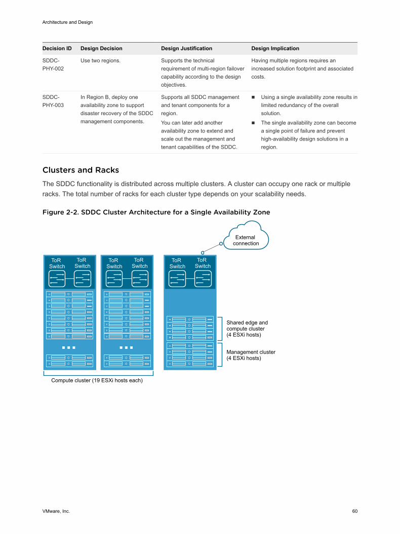
Decision ID Design Decision Design Justification Design Implication
SDDC-PHY-002
Use two regions. Supports the technicalrequirement of multi-region failovercapability according to the designobjectives.
Having multiple regions requires anincreased solution footprint and associatedcosts.
SDDC-PHY-003
In Region B, deploy oneavailability zone to supportdisaster recovery of the SDDCmanagement components.
Supports all SDDC managementand tenant components for aregion.
You can later add anotheravailability zone to extend andscale out the management andtenant capabilities of the SDDC.
n Using a single availability zone results inlimited redundancy of the overallsolution.
n The single availability zone can becomea single point of failure and preventhigh-availability design solutions in aregion.
Clusters and Racks The SDDC functionality is distributed across multiple clusters. A cluster can occupy one rack or multipleracks. The total number of racks for each cluster type depends on your scalability needs.
Figure 2-2. SDDC Cluster Architecture for a Single Availability Zone
ToR Switch
ToR Switch
ToR Switch
ToR Switch
Compute cluster (19 ESXi hosts each)
Shared edge andcompute cluster(4 ESXi hosts)
Management cluster(4 ESXi hosts)
External connection
ToR Switch
ToR Switch
Architecture and Design
VMware, Inc. 60
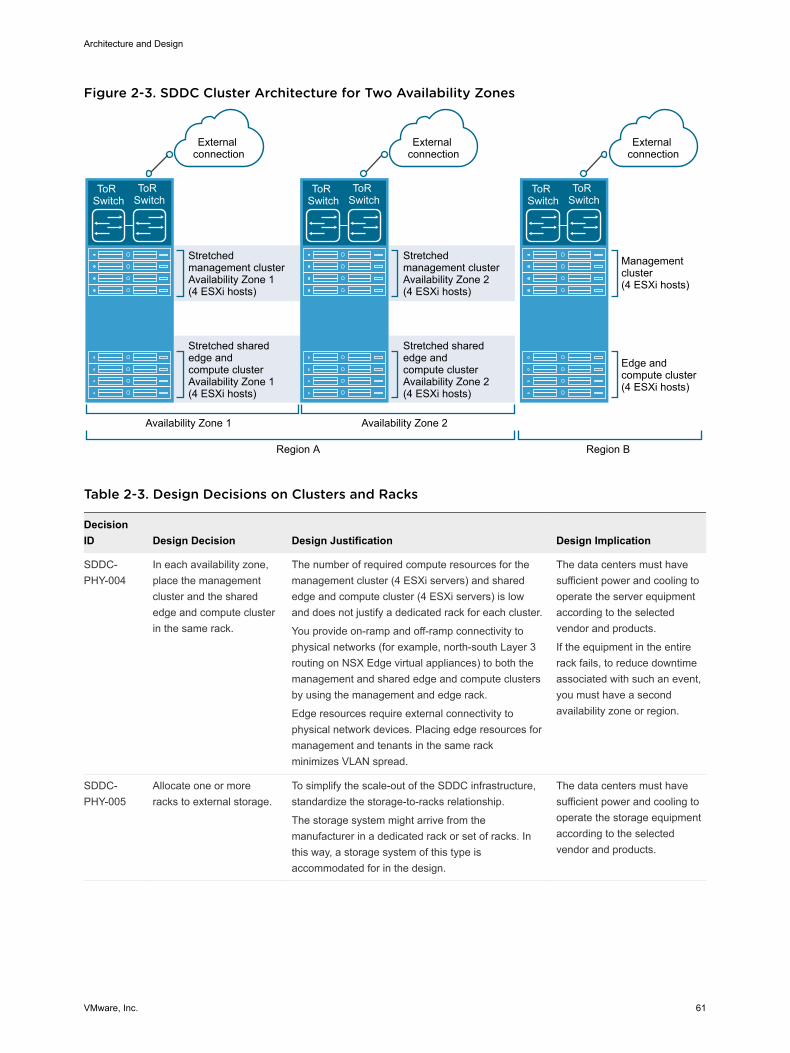
Figure 2-3. SDDC Cluster Architecture for Two Availability Zones
Availability Zone 1
Management cluster(4 ESXi hosts)
Еdge andcompute cluster(4 ESXi hosts)
ToR Switch
ToR Switch
Stretchedmanagement clusterAvailability Zone 1(4 ESXi hosts)
Stretched sharededge andcompute clusterAvailability Zone 1(4 ESXi hosts)
External connection
External connection
External connection
ToR Switch
ToR Switch
Stretchedmanagement clusterAvailability Zone 2(4 ESXi hosts)
Stretched sharededge and compute clusterAvailability Zone 2(4 ESXi hosts)
ToR Switch
ToR Switch
Availability Zone 2
Region A Region B
Table 2-3. Design Decisions on Clusters and Racks
DecisionID Design Decision Design Justification Design Implication
SDDC-PHY-004
In each availability zone,place the managementcluster and the sharededge and compute clusterin the same rack.
The number of required compute resources for themanagement cluster (4 ESXi servers) and sharededge and compute cluster (4 ESXi servers) is lowand does not justify a dedicated rack for each cluster.
You provide on-ramp and off-ramp connectivity tophysical networks (for example, north-south Layer 3routing on NSX Edge virtual appliances) to both themanagement and shared edge and compute clustersby using the management and edge rack.
Edge resources require external connectivity tophysical network devices. Placing edge resources formanagement and tenants in the same rackminimizes VLAN spread.
The data centers must havesufficient power and cooling tooperate the server equipmentaccording to the selectedvendor and products.
If the equipment in the entirerack fails, to reduce downtimeassociated with such an event,you must have a secondavailability zone or region.
SDDC-PHY-005
Allocate one or moreracks to external storage.
To simplify the scale-out of the SDDC infrastructure,standardize the storage-to-racks relationship.
The storage system might arrive from themanufacturer in a dedicated rack or set of racks. Inthis way, a storage system of this type isaccommodated for in the design.
The data centers must havesufficient power and cooling tooperate the storage equipmentaccording to the selectedvendor and products.
Architecture and Design
VMware, Inc. 61
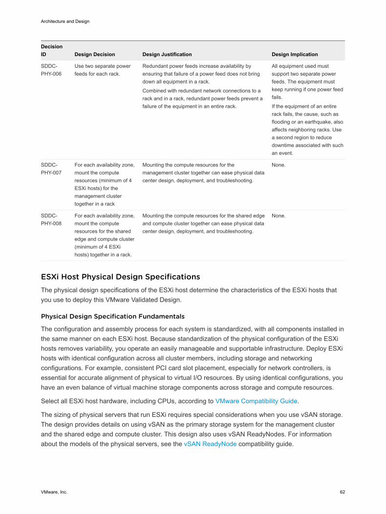
DecisionID Design Decision Design Justification Design Implication
SDDC-PHY-006
Use two separate powerfeeds for each rack.
Redundant power feeds increase availability byensuring that failure of a power feed does not bringdown all equipment in a rack.
Combined with redundant network connections to arack and in a rack, redundant power feeds prevent afailure of the equipment in an entire rack.
All equipment used mustsupport two separate powerfeeds. The equipment mustkeep running if one power feedfails.
If the equipment of an entirerack fails, the cause, such asflooding or an earthquake, alsoaffects neighboring racks. Usea second region to reducedowntime associated with suchan event.
SDDC-PHY-007
For each availability zone,mount the computeresources (minimum of 4ESXi hosts) for themanagement clustertogether in a rack
Mounting the compute resources for themanagement cluster together can ease physical datacenter design, deployment, and troubleshooting.
None.
SDDC-PHY-008
For each availability zone,mount the computeresources for the sharededge and compute cluster(minimum of 4 ESXihosts) together in a rack.
Mounting the compute resources for the shared edgeand compute cluster together can ease physical datacenter design, deployment, and troubleshooting.
None.
ESXi Host Physical Design Specifications The physical design specifications of the ESXi host determine the characteristics of the ESXi hosts thatyou use to deploy this VMware Validated Design.
Physical Design Specification Fundamentals
The configuration and assembly process for each system is standardized, with all components installed inthe same manner on each ESXi host. Because standardization of the physical configuration of the ESXihosts removes variability, you operate an easily manageable and supportable infrastructure. Deploy ESXihosts with identical configuration across all cluster members, including storage and networkingconfigurations. For example, consistent PCI card slot placement, especially for network controllers, isessential for accurate alignment of physical to virtual I/O resources. By using identical configurations, youhave an even balance of virtual machine storage components across storage and compute resources.
Select all ESXi host hardware, including CPUs, according to VMware Compatibility Guide.
The sizing of physical servers that run ESXi requires special considerations when you use vSAN storage.The design provides details on using vSAN as the primary storage system for the management clusterand the shared edge and compute cluster. This design also uses vSAN ReadyNodes. For informationabout the models of the physical servers, see the vSAN ReadyNode compatibility guide.
Architecture and Design
VMware, Inc. 62
This design supports using a storage system other than vSAN as the primary storage system for themanagement and shared edge and compute clusters. However, using a non-vSAN storage is not a part ofthe documentation of this validated design. For details on vSAN capacity and performance characteristicsto aid your selection of non-vSAN storage, see Physical Storage Design .
n An average-size VM has two vCPUs with 4 GB of RAM.
n A typical spec 2U ESXi host can run 60 average-size VMs.
Table 2-4. Design Decisions on the Physical Design of the ESXi Hosts
Decision ID Design Decision Design Justification Design Implication
SDDC-PHY-009
Use vSAN ReadyNodeswith vSAN storage.
Using vSAN ReadyNodes ensures fullcompatibility with vSAN at deployment.
Hardware choices might belimited.
SDDC-PHY-010
Verify that all nodes haveuniform configuration acrossa cluster.
A balanced cluster has more predictableperformance even during hardware failures.In addition, the impact on performance duringresync or rebuild is minimal if the cluster isbalanced.
Apply vendor sourcing,budgeting, and procurementconsiderations for uniform servernodes, on a per cluster basis.
ESXi Host Memory
The amount of memory required for compute clusters varies according to the workloads running in thecluster. When sizing memory for compute cluster hosts, consider the admission control setting (n+1),which reserves the resources of one host for failover or maintenance.
The number of vSAN disk groups and disks that an ESXi host manages determines the memoryrequirements. To support the maximum number of disk groups, you must provide 32 GB of RAM. Formore information about disk groups, including design and sizing guidance, see Administering VMwarevSAN from the vSphere documentation.
Table 2-5. Design Decisions on the ESXi Host Memory
Decision ID Design Decision Design Justification Design Implication
SDDC-PHY-011
Set up each ESXi host in themanagement cluster with aminimum of 256 GB RAM.
The management and edge VMs in this clusterrequire a total of 453 GB RAM.
The remaining RAM is available for newcapabilities of the SDDC such as deployment ofVMware NSX-T or VMware PKS.
In a four-node cluster, only 768GB is available for use due tothe n+1 vSphere HA setting.
ESXi Host Boot Device
Minimum boot disk size for ESXi in SCSI-based devices (SAS, SATA, or SAN) is greater than 5 GB. ESXican be deployed using stateful local SAN SCSI boot devices, or by using vSphere Auto Deploy.
Selecting a boot device type and size for vSAN has the following considerations:
n vSAN does not support stateless vSphere Auto Deploy.
n Device types as ESXi boot devices
n USB or SD embedded devices. The USB or SD flash drive must be at least 4 GB.
Architecture and Design
VMware, Inc. 63
n SATADOM devices. The size of the boot device per host must be at least 16 GB.
See VMware vSAN Design and Sizing Guide to select the option that best fits your hardware.
Physical Networking Design Design of the physical SDDC network includes defining the network topology for connecting the physicalswitches and the ESXi hosts, determining switch port settings for VLANs and link aggregation, anddesigning routing. VMware Validated Design for Software-Defined Data Center can use most enterprise-grade physical network architectures.
Switch Types and Network Connectivity Follow best practices for physical switches, switch connectivity, setup of VLANs and subnets, and accessport settings.
Top of Rack Physical Switches
When configuring top of rack (ToR) switches, consider the following best practices.
n Configure redundant physical switches to enhance availability.
n Configure switch ports that connect to ESXi hosts manually as trunk ports. Virtual switches arepassive devices and do not support trunking protocols, such as Dynamic Trunking Protocol (DTP).
n Modify the Spanning Tree Protocol (STP) on any port that is connected to an ESXi NIC to reduce thetime it takes to transition ports over to the forwarding state, for example, using the Trunk PortFastfeature on a Cisco physical switch.
n Provide DHCP or DHCP Helper capabilities on all VLANs that are used by the management andVXLAN VMkernel ports. This setup simplifies the configuration by using DHCP to assign IP addressbased on the IP subnet in use.
n Configure jumbo frames on all switch ports, inter-switch link (ISL) and switched virtual interfaces(SVIs).
Top of Rack Connectivity and Network Settings
Each ESXi host is connected redundantly to the SDDC network fabric ToR switches by using a minimumof two 10-GbE ports (two 25-GbE or faster ports are recommended). Configure the ToR switches toprovide all necessary VLANs via an 802.1Q trunk. These redundant connections use features of vSphereDistributed Switch and NSX for vSphere to guarantee that no physical interface is overrun and redundantpaths are used as long as they are available.
Architecture and Design
VMware, Inc. 64
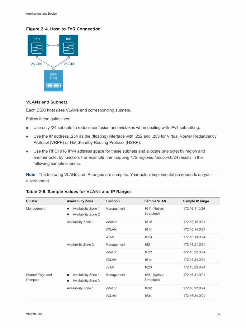
Figure 2-4. Host-to-ToR Connection
ToR ToR
ESXiHost
25 GbE 25 GbE
VLANs and Subnets
Each ESXi host uses VLANs and corresponding subnets.
Follow these guidelines:
n Use only /24 subnets to reduce confusion and mistakes when dealing with IPv4 subnetting.
n Use the IP address .254 as the (floating) interface with .252 and .253 for Virtual Router RedundancyProtocol (VRPP) or Hot Standby Routing Protocol (HSRP).
n Use the RFC1918 IPv4 address space for these subnets and allocate one octet by region andanother octet by function. For example, the mapping 172.regionid.function.0/24 results in thefollowing sample subnets.
Note The following VLANs and IP ranges are samples. Your actual implementation depends on yourenvironment.
Table 2-6. Sample Values for VLANs and IP Ranges
Cluster Availability Zone Function Sample VLAN Sample IP range
Management n Availability Zone 1
n Availability Zone 2
Management 1611 (Native,Stretched)
172.16.11.0/24
Availability Zone 1 vMotion 1612 172.16.12.0/24
VXLAN 1614 172.16.14.0/24
vSAN 1613 172.16.13.0/24
Availability Zone 2 Management 1621 172.16.21.0/24
vMotion 1622 172.16.22.0/24
VXLAN 1614 172.16.24.0/24
vSAN 1623 172.16.23.0/24
Shared Edge andCompute
n Availability Zone 1
n Availability Zone 2
Management 1631 (Native,Stretched)
172.16.31.0/24
Availability Zone 1 vMotion 1632 172.16.32.0/24
VXLAN 1634 172.16.34.0/24
Architecture and Design
VMware, Inc. 65
Cluster Availability Zone Function Sample VLAN Sample IP range
vSAN 1633 172.16.33.0/24
Availability Zone 2 Management 1641 172.16.41.0/24
vMotion 1642 172.16.42.0/24
VXLAN 1634 172.16.44.0/24
vSAN 1643 172.16.43.0/25
Note When NSX prepares the stretched cluster, the VXLAN VLANs have the same VLAN ID in bothAvailability Zone 1 and Availability Zone 2. The VLAN ID must exist in both availability zones but mustmap to a different routeable IP space in each zone so that NSX virtual tunnel end-points (VTEPs) cancommunicate.
Access Port Network Settings
Configure additional network settings on the access ports that connect the ToR switches to thecorresponding servers.
Spanning Tree Protocol(STP)
Although this design does not use the STP, switches usually come withSTP configured by default. Designate the access ports as trunk PortFast.
Trunking Configure the VLANs as members of a 802.1Q trunk with the managementVLAN acting as the native VLAN.
MTU Set MTU for all VLANS and SVIs to the value for jumbo frames forconsistency purposes.
DHCP helper Configure the VIF of the Management and VXLAN subnet as a DHCPproxy.
Multicast Configure IGMP snooping on the ToR switches and include an IGMPquerier on each VXLAN VLAN.
Connectivity Between Regions
The SDDC management networks, VXLAN kernel ports, and the edge and compute VXLAN kernelports of the two regions must be connected. These connections can be over a VPN tunnel, point-to-pointcircuits, MPLS, and so on. End users must be able to reach the public-facing network segments (publicmanagement and tenant networks) of both regions.
The region interconnectivity design must support jumbo frames, and ensure that latency is less than 100ms. For more details on the requirements for region interconnectivity, see the Cross-VC NSX DesignGuide.
The design of a solution for region interconnectivity is out of scope for this VMware Validated Design.
Architecture and Design
VMware, Inc. 66
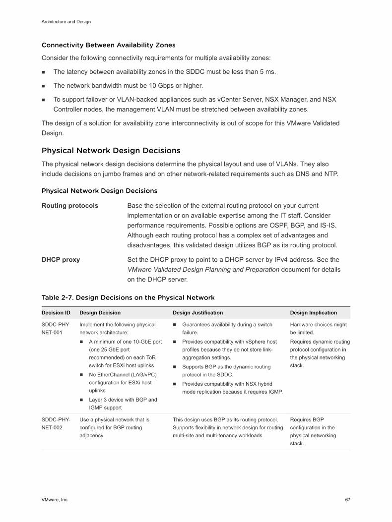
Connectivity Between Availability Zones
Consider the following connectivity requirements for multiple availability zones:
n The latency between availability zones in the SDDC must be less than 5 ms.
n The network bandwidth must be 10 Gbps or higher.
n To support failover or VLAN-backed appliances such as vCenter Server, NSX Manager, and NSXController nodes, the management VLAN must be stretched between availability zones.
The design of a solution for availability zone interconnectivity is out of scope for this VMware ValidatedDesign.
Physical Network Design Decisions The physical network design decisions determine the physical layout and use of VLANs. They alsoinclude decisions on jumbo frames and on other network-related requirements such as DNS and NTP.
Physical Network Design Decisions
Routing protocols Base the selection of the external routing protocol on your currentimplementation or on available expertise among the IT staff. Considerperformance requirements. Possible options are OSPF, BGP, and IS-IS.Although each routing protocol has a complex set of advantages anddisadvantages, this validated design utilizes BGP as its routing protocol.
DHCP proxy Set the DHCP proxy to point to a DHCP server by IPv4 address. See theVMware Validated Design Planning and Preparation document for detailson the DHCP server.
Table 2-7. Design Decisions on the Physical Network
Decision ID Design Decision Design Justification Design Implication
SDDC-PHY-NET-001
Implement the following physicalnetwork architecture:
n A minimum of one 10-GbE port(one 25 GbE portrecommended) on each ToRswitch for ESXi host uplinks
n No EtherChannel (LAG/vPC)configuration for ESXi hostuplinks
n Layer 3 device with BGP andIGMP support
n Guarantees availability during a switchfailure.
n Provides compatibility with vSphere hostprofiles because they do not store link-aggregation settings.
n Supports BGP as the dynamic routingprotocol in the SDDC.
n Provides compatibility with NSX hybridmode replication because it requires IGMP.
Hardware choices mightbe limited.
Requires dynamic routingprotocol configuration inthe physical networkingstack.
SDDC-PHY-NET-002
Use a physical network that isconfigured for BGP routingadjacency.
This design uses BGP as its routing protocol.Supports flexibility in network design for routingmulti-site and multi-tenancy workloads.
Requires BGPconfiguration in thephysical networkingstack.
Architecture and Design
VMware, Inc. 67
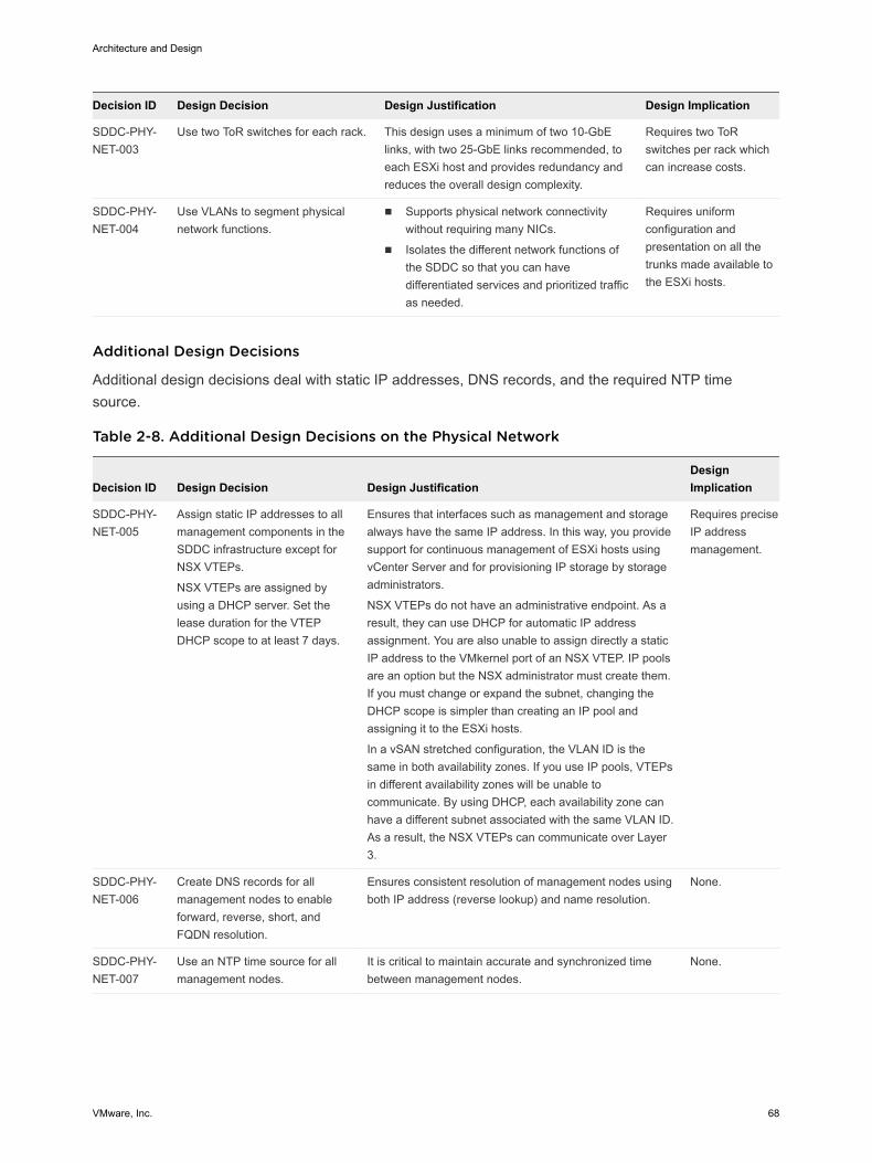
Decision ID Design Decision Design Justification Design Implication
SDDC-PHY-NET-003
Use two ToR switches for each rack. This design uses a minimum of two 10-GbElinks, with two 25-GbE links recommended, toeach ESXi host and provides redundancy andreduces the overall design complexity.
Requires two ToRswitches per rack whichcan increase costs.
SDDC-PHY-NET-004
Use VLANs to segment physicalnetwork functions.
n Supports physical network connectivitywithout requiring many NICs.
n Isolates the different network functions ofthe SDDC so that you can havedifferentiated services and prioritized trafficas needed.
Requires uniformconfiguration andpresentation on all thetrunks made available tothe ESXi hosts.
Additional Design Decisions
Additional design decisions deal with static IP addresses, DNS records, and the required NTP timesource.
Table 2-8. Additional Design Decisions on the Physical Network
Decision ID Design Decision Design JustificationDesignImplication
SDDC-PHY-NET-005
Assign static IP addresses to allmanagement components in theSDDC infrastructure except forNSX VTEPs.
NSX VTEPs are assigned byusing a DHCP server. Set thelease duration for the VTEPDHCP scope to at least 7 days.
Ensures that interfaces such as management and storagealways have the same IP address. In this way, you providesupport for continuous management of ESXi hosts usingvCenter Server and for provisioning IP storage by storageadministrators.
NSX VTEPs do not have an administrative endpoint. As aresult, they can use DHCP for automatic IP addressassignment. You are also unable to assign directly a staticIP address to the VMkernel port of an NSX VTEP. IP poolsare an option but the NSX administrator must create them.If you must change or expand the subnet, changing theDHCP scope is simpler than creating an IP pool andassigning it to the ESXi hosts.
In a vSAN stretched configuration, the VLAN ID is thesame in both availability zones. If you use IP pools, VTEPsin different availability zones will be unable tocommunicate. By using DHCP, each availability zone canhave a different subnet associated with the same VLAN ID.As a result, the NSX VTEPs can communicate over Layer3.
Requires preciseIP addressmanagement.
SDDC-PHY-NET-006
Create DNS records for allmanagement nodes to enableforward, reverse, short, andFQDN resolution.
Ensures consistent resolution of management nodes usingboth IP address (reverse lookup) and name resolution.
None.
SDDC-PHY-NET-007
Use an NTP time source for allmanagement nodes.
It is critical to maintain accurate and synchronized timebetween management nodes.
None.
Architecture and Design
VMware, Inc. 68
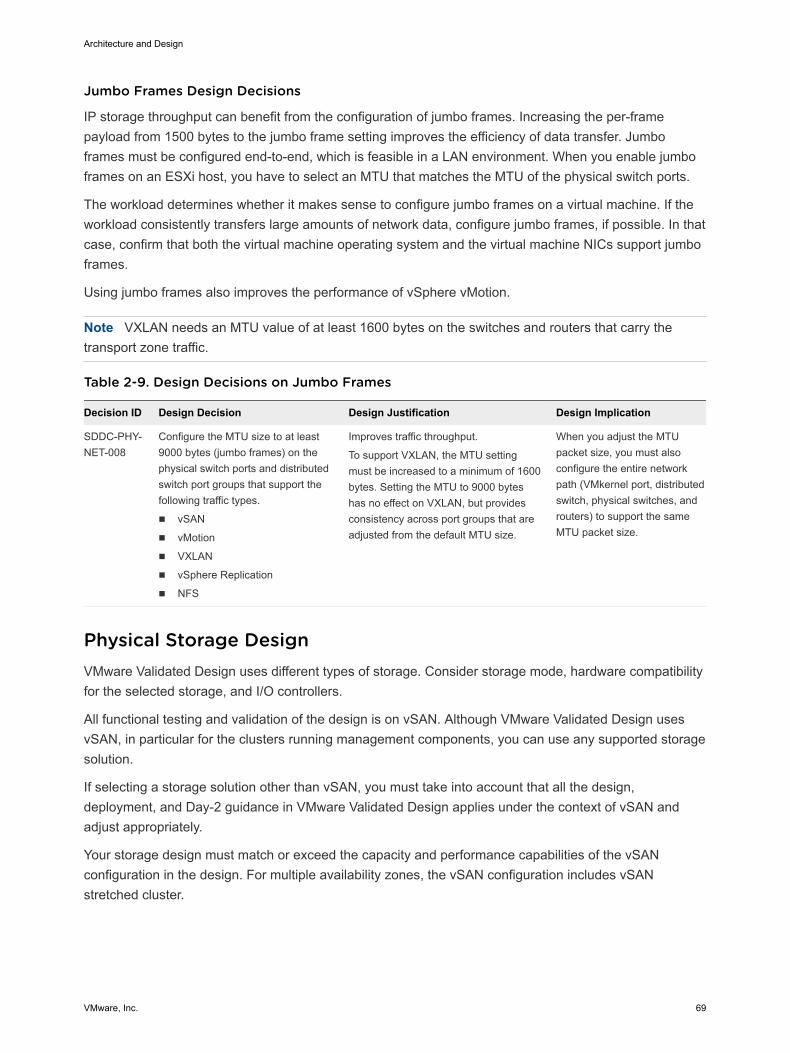
Jumbo Frames Design Decisions
IP storage throughput can benefit from the configuration of jumbo frames. Increasing the per-framepayload from 1500 bytes to the jumbo frame setting improves the efficiency of data transfer. Jumboframes must be configured end-to-end, which is feasible in a LAN environment. When you enable jumboframes on an ESXi host, you have to select an MTU that matches the MTU of the physical switch ports.
The workload determines whether it makes sense to configure jumbo frames on a virtual machine. If theworkload consistently transfers large amounts of network data, configure jumbo frames, if possible. In thatcase, confirm that both the virtual machine operating system and the virtual machine NICs support jumboframes.
Using jumbo frames also improves the performance of vSphere vMotion.
Note VXLAN needs an MTU value of at least 1600 bytes on the switches and routers that carry thetransport zone traffic.
Table 2-9. Design Decisions on Jumbo Frames
Decision ID Design Decision Design Justification Design Implication
SDDC-PHY-NET-008
Configure the MTU size to at least9000 bytes (jumbo frames) on thephysical switch ports and distributedswitch port groups that support thefollowing traffic types.
n vSAN
n vMotion
n VXLAN
n vSphere Replication
n NFS
Improves traffic throughput.
To support VXLAN, the MTU settingmust be increased to a minimum of 1600bytes. Setting the MTU to 9000 byteshas no effect on VXLAN, but providesconsistency across port groups that areadjusted from the default MTU size.
When you adjust the MTUpacket size, you must alsoconfigure the entire networkpath (VMkernel port, distributedswitch, physical switches, androuters) to support the sameMTU packet size.
Physical Storage Design VMware Validated Design uses different types of storage. Consider storage mode, hardware compatibilityfor the selected storage, and I/O controllers.
All functional testing and validation of the design is on vSAN. Although VMware Validated Design usesvSAN, in particular for the clusters running management components, you can use any supported storagesolution.
If selecting a storage solution other than vSAN, you must take into account that all the design,deployment, and Day-2 guidance in VMware Validated Design applies under the context of vSAN andadjust appropriately.
Your storage design must match or exceed the capacity and performance capabilities of the vSANconfiguration in the design. For multiple availability zones, the vSAN configuration includes vSANstretched cluster.
Architecture and Design
VMware, Inc. 69
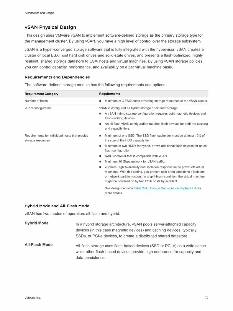
vSAN Physical Design This design uses VMware vSAN to implement software-defined storage as the primary storage type forthe management cluster. By using vSAN, you have a high level of control over the storage subsystem.
vSAN is a hyper-converged storage software that is fully integrated with the hypervisor. vSAN creates acluster of local ESXi host hard disk drives and solid-state drives, and presents a flash-optimized, highlyresilient, shared storage datastore to ESXi hosts and virtual machines. By using vSAN storage policies,you can control capacity, performance, and availability on a per virtual machine basis.
Requirements and Dependencies
The software-defined storage module has the following requirements and options.
Requirement Category Requirements
Number of hosts n Minimum of 3 ESXi hosts providing storage resources to the vSAN cluster.
vSAN configuration vSAN is configured as hybrid storage or all-flash storage.
n A vSAN hybrid storage configuration requires both magnetic devices andflash caching devices.
n An all-flash vSAN configuration requires flash devices for both the cachingand capacity tiers.
Requirements for individual hosts that providestorage resources
n Minimum of one SSD. The SSD flash cache tier must be at least 10% ofthe size of the HDD capacity tier.
n Minimum of two HDDs for hybrid, or two additional flash devices for an all-flash configuration
n RAID controller that is compatible with vSAN.
n Minimum 10 Gbps network for vSAN traffic.
n vSphere High Availability host isolation response set to power off virtualmachines. With this setting, you prevent split-brain conditions if isolationor network partition occurs. In a split-brain condition, the virtual machinemight be powered on by two ESXi hosts by accident.
See design decision Table 2-33. Design Decisions on vSphere HA formore details.
Hybrid Mode and All-Flash Mode
vSAN has two modes of operation: all-flash and hybrid.
Hybrid Mode In a hybrid storage architecture, vSAN pools server-attached capacitydevices (in this case magnetic devices) and caching devices, typicallySSDs, or PCI-e devices, to create a distributed shared datastore.
All-Flash Mode All-flash storage uses flash-based devices (SSD or PCI-e) as a write cachewhile other flash-based devices provide high endurance for capacity anddata persistence.
Architecture and Design
VMware, Inc. 70
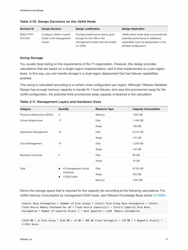
Table 2-10. Design Decisions on the vSAN Mode
Decision ID Design Decision Design Justification Design Implication
SDDC-PHY-STO-001
Configure vSAN in hybridmode in the managementcluster.
Provides performance that is goodenough for the VMs in themanagement cluster that are hostedon vSAN.
vSAN hybrid mode does not provide thepotential performance or additionalcapabilities such as deduplication of anall-flash configuration.
Sizing Storage
You usually base sizing on the requirements of the IT organization. However, this design providescalculations that are based on a single-region implementation, and is then implemented on a per-regionbasis. In this way, you can handle storage in a dual-region deployment that has failover capabilitiesenabled.
This sizing is calculated according to a certain node configuration per region. Although VMware ValidatedDesign has enough memory capacity to handle N-1 host failures, and uses thin-provisioned swap for thevSAN configuration, the potential think-provisioned swap capacity is factored in the calculation.
Table 2-11. Management Layers and Hardware Sizes
Category Quantity Resource Type Capacity Consumption
Physical Infrastructure (ESXi) 4 Memory 1024 GB
Virtual Infrastructure 17 Disk 1,199 GB
Swap 108 GB
Operations Management 10 Disk 6,272 GB
Swap 170 GB
Cloud Management 14 Disk 1,200 GB
Swap 144 GB
Business Continuity 2 Disk 58 GB
Swap 16 GB
Total n 43 management virtualmachines
n 4 ESXi hosts
Disk 8,729 GB
Swap 438 GB
Memory 1024 GB
Derive the storage space that is required for the capacity tier according to the following calculations. ForvSAN memory consumption by management ESXi hosts, see VMware Knowledge Base article 2113954.
[Static Base Consumption + (Number of Disk Groups * (Static Disk Group Base Consumption + (Static
Flash Device Memory Overhead Per GB * Flash Device Capactiy))) + (Static Capacity Disk Base
Consumption * Number of Capacity Disks) ] * Host Quantity = vSAN Memory Consumption
[5426 MB + (1 Disk Group * (636 MB + (8 MB * 300 GB Flash Storage))) + (70 MB * 2 Magnetic Disks)] *
4 ESXi Hosts
Architecture and Design
VMware, Inc. 71

[5426 MB + (1 Disk Groups * (636 MB + 2400 MB)) + 140 MB] = 8602 MB / 1024 = 8.4 GB vSAN Memory
Consumption per host or 33.6 GB for a four node cluster
Derive the consumption of storage space by the management virtual machines according to the followingcalculations. See VMware vSAN Design and Sizing Guide.
VM Raw Storage Requirements (without FTT) + VM Swap (without FTT) = Virtual Machine Raw Capacity
Requirements
Virtual Machine Raw Capacity Requirements * FTT = Final Virtual Machine Raw Capacity Requirements
8,730 GB Disk + 430 GB Swap = 9,160 GB Virtual Machine Raw Capacity Requirements
9,160 GB Virtual Machine Raw Capacity Requirements * 2 (FTT=1, RAID1) = 18,320 GB Final Virtual
Machine Raw Capacity Requirements
Derive the requirements for total storage space for the capacity tier according to the followingcalculations:
vSAN Memory Consumption + Final Virtual Machine Raw Capacity Requirements = Total Raw Storage Capacity
Total Raw Storage Capacity * 30% Slack Overhead * 1% On-disk Format Overhead * 0.12% Checksum
Overhead = Raw Unformatted Storage Capacity
OR
Total Raw Storage Capacity * 30% Slack Overhead * 1% On-disk Format Overhead * 0.12% Checksum
Overhead * 20% Estimated Growth = Raw Unformatted Storage Capacity (with 20% Growth Capacity)
Raw Unformatted Storage Capacity / ESXi Quantity = Final Raw Storage Capacity per Host
Based on the calculations for the vSAN memory consumption and the management virtual machineconsumption, calculate the final raw storage capacity required for the cluster and per the ESXi hosts.
34 GB vSAN Memory Consumption + 18,334 GB VM Raw Capactiy = 18,368 GB Total Raw Storage Capacity
18,368 GB Total Raw Storage Capacity * 30% Slack Overhead * 1% On-disk Format Overhead * 0.12%
Overhead ≈ 24,146 ≈ 24 TB Raw Unformatted Storage Capacity
24 TB Raw Unformatted Storage Capacity / 4 ESXi hosts ≈ 6 TB Final Raw Storage Capacity per host
18,368 GB Total Raw Storage Capacity * 30% Slack Overhead * 1% On-disk Format Overhead * 0.12%
Overhead * 20% Estimated Growth ≈ 28,975 GB ≈ 29 TB Raw Unformatted Storage Capacity (with 20% Growth
Capacity)
29 TB Raw Unformatted Storage Capacity / 4 ESXi hosts ≈ 8 TB Final Raw Storage Capacity per host
Determine the storage space that is required for the caching tier according to the following calculations:
Raw Unformatted Storage Capacity * 50% * 10% = Total Flash Device Capacity
Total Flash Device Capacity / ESXi Quantity = Final Flash Device Capacity per Host
24 TB Raw Unformatted Storage Capacity * 50% * 10% Cache Required ≈ 1.2 TB Flash Device Capacity
1.2 TB Flash Device Storage Capacity / 4 ESXi Hosts ≈ 300 GB of Flash Device Capacity per Host
Architecture and Design
VMware, Inc. 72
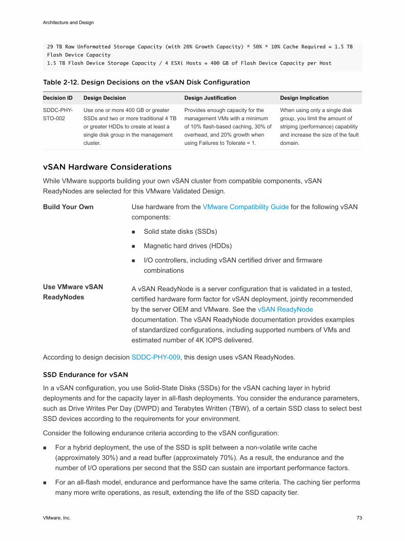
29 TB Raw Unformatted Storage Capacity (with 20% Growth Capacity) * 50% * 10% Cache Required ≈ 1.5 TB
Flash Device Capacity
1.5 TB Flash Device Storage Capacity / 4 ESXi Hosts ≈ 400 GB of Flash Device Capacity per Host
Table 2-12. Design Decisions on the vSAN Disk Configuration
Decision ID Design Decision Design Justification Design Implication
SDDC-PHY-STO-002
Use one or more 400 GB or greaterSSDs and two or more traditional 4 TBor greater HDDs to create at least asingle disk group in the managementcluster.
Provides enough capacity for themanagement VMs with a minimumof 10% flash-based caching, 30% ofoverhead, and 20% growth whenusing Failures to Tolerate = 1.
When using only a single diskgroup, you limit the amount ofstriping (performance) capabilityand increase the size of the faultdomain.
vSAN Hardware Considerations While VMware supports building your own vSAN cluster from compatible components, vSANReadyNodes are selected for this VMware Validated Design.
Build Your Own Use hardware from the VMware Compatibility Guide for the following vSANcomponents:
n Solid state disks (SSDs)
n Magnetic hard drives (HDDs)
n I/O controllers, including vSAN certified driver and firmwarecombinations
Use VMware vSANReadyNodes
A vSAN ReadyNode is a server configuration that is validated in a tested,certified hardware form factor for vSAN deployment, jointly recommendedby the server OEM and VMware. See the vSAN ReadyNodedocumentation. The vSAN ReadyNode documentation provides examplesof standardized configurations, including supported numbers of VMs andestimated number of 4K IOPS delivered.
According to design decision SDDC-PHY-009, this design uses vSAN ReadyNodes.
SSD Endurance for vSAN
In a vSAN configuration, you use Solid-State Disks (SSDs) for the vSAN caching layer in hybriddeployments and for the capacity layer in all-flash deployments. You consider the endurance parameters,such as Drive Writes Per Day (DWPD) and Terabytes Written (TBW), of a certain SSD class to select bestSSD devices according to the requirements for your environment.
Consider the following endurance criteria according to the vSAN configuration:
n For a hybrid deployment, the use of the SSD is split between a non-volatile write cache(approximately 30%) and a read buffer (approximately 70%). As a result, the endurance and thenumber of I/O operations per second that the SSD can sustain are important performance factors.
n For an all-flash model, endurance and performance have the same criteria. The caching tier performsmany more write operations, as result, extending the life of the SSD capacity tier.
Architecture and Design
VMware, Inc. 73
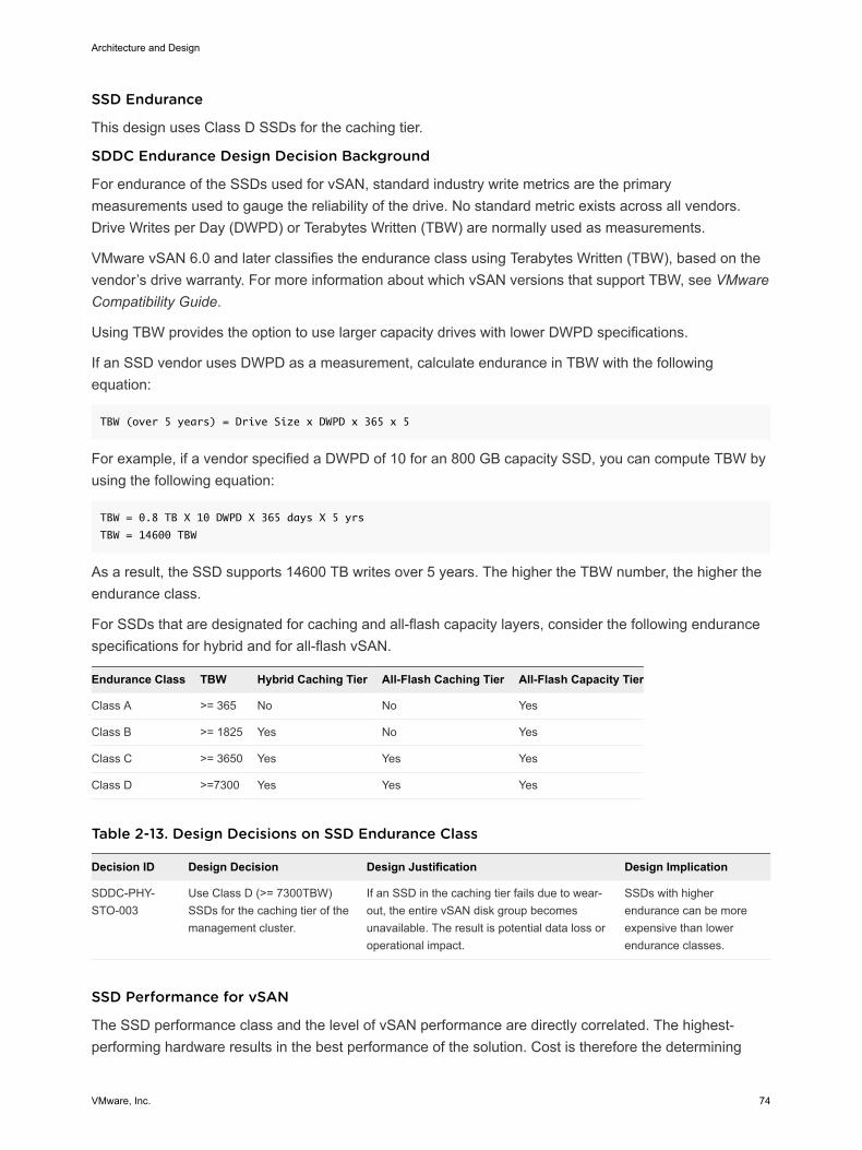
SSD Endurance
This design uses Class D SSDs for the caching tier.
SDDC Endurance Design Decision Background
For endurance of the SSDs used for vSAN, standard industry write metrics are the primarymeasurements used to gauge the reliability of the drive. No standard metric exists across all vendors.Drive Writes per Day (DWPD) or Terabytes Written (TBW) are normally used as measurements.
VMware vSAN 6.0 and later classifies the endurance class using Terabytes Written (TBW), based on thevendor’s drive warranty. For more information about which vSAN versions that support TBW, see VMwareCompatibility Guide.
Using TBW provides the option to use larger capacity drives with lower DWPD specifications.
If an SSD vendor uses DWPD as a measurement, calculate endurance in TBW with the followingequation:
TBW (over 5 years) = Drive Size x DWPD x 365 x 5
For example, if a vendor specified a DWPD of 10 for an 800 GB capacity SSD, you can compute TBW byusing the following equation:
TBW = 0.8 TB X 10 DWPD X 365 days X 5 yrs
TBW = 14600 TBW
As a result, the SSD supports 14600 TB writes over 5 years. The higher the TBW number, the higher theendurance class.
For SSDs that are designated for caching and all-flash capacity layers, consider the following endurancespecifications for hybrid and for all-flash vSAN.
Endurance Class TBW Hybrid Caching Tier All-Flash Caching Tier All-Flash Capacity Tier
Class A >= 365 No No Yes
Class B >= 1825 Yes No Yes
Class C >= 3650 Yes Yes Yes
Class D >=7300 Yes Yes Yes
Table 2-13. Design Decisions on SSD Endurance Class
Decision ID Design Decision Design Justification Design Implication
SDDC-PHY-STO-003
Use Class D (>= 7300TBW)SSDs for the caching tier of themanagement cluster.
If an SSD in the caching tier fails due to wear-out, the entire vSAN disk group becomesunavailable. The result is potential data loss oroperational impact.
SSDs with higherendurance can be moreexpensive than lowerendurance classes.
SSD Performance for vSAN
The SSD performance class and the level of vSAN performance are directly correlated. The highest-performing hardware results in the best performance of the solution. Cost is therefore the determining
Architecture and Design
VMware, Inc. 74
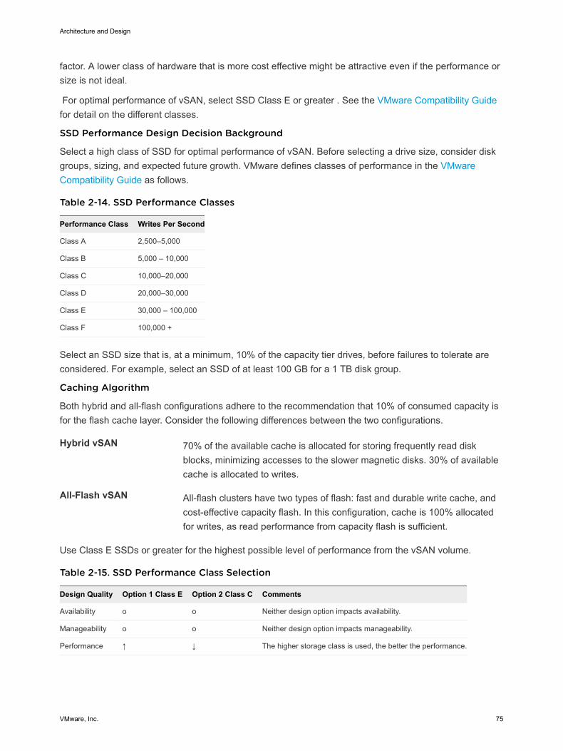
factor. A lower class of hardware that is more cost effective might be attractive even if the performance orsize is not ideal.
For optimal performance of vSAN, select SSD Class E or greater . See the VMware Compatibility Guidefor detail on the different classes.
SSD Performance Design Decision Background
Select a high class of SSD for optimal performance of vSAN. Before selecting a drive size, consider diskgroups, sizing, and expected future growth. VMware defines classes of performance in the VMwareCompatibility Guide as follows.
Table 2-14. SSD Performance Classes
Performance Class Writes Per Second
Class A 2,500–5,000
Class B 5,000 – 10,000
Class C 10,000–20,000
Class D 20,000–30,000
Class E 30,000 – 100,000
Class F 100,000 +
Select an SSD size that is, at a minimum, 10% of the capacity tier drives, before failures to tolerate areconsidered. For example, select an SSD of at least 100 GB for a 1 TB disk group.
Caching Algorithm
Both hybrid and all-flash configurations adhere to the recommendation that 10% of consumed capacity isfor the flash cache layer. Consider the following differences between the two configurations.
Hybrid vSAN 70% of the available cache is allocated for storing frequently read diskblocks, minimizing accesses to the slower magnetic disks. 30% of availablecache is allocated to writes.
All-Flash vSAN All-flash clusters have two types of flash: fast and durable write cache, andcost-effective capacity flash. In this configuration, cache is 100% allocatedfor writes, as read performance from capacity flash is sufficient.
Use Class E SSDs or greater for the highest possible level of performance from the vSAN volume.
Table 2-15. SSD Performance Class Selection
Design Quality Option 1 Class E Option 2 Class C Comments
Availability o o Neither design option impacts availability.
Manageability o o Neither design option impacts manageability.
Performance ↑ ↓ The higher storage class is used, the better the performance.
Architecture and Design
VMware, Inc. 75
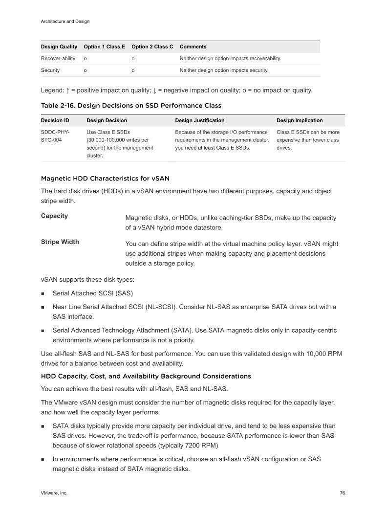
Design Quality Option 1 Class E Option 2 Class C Comments
Recover-ability o o Neither design option impacts recoverability.
Security o o Neither design option impacts security.
Legend: ↑ = positive impact on quality; ↓ = negative impact on quality; o = no impact on quality.
Table 2-16. Design Decisions on SSD Performance Class
Decision ID Design Decision Design Justification Design Implication
SDDC-PHY-STO-004
Use Class E SSDs(30,000-100,000 writes persecond) for the managementcluster.
Because of the storage I/O performancerequirements in the management cluster,you need at least Class E SSDs.
Class E SSDs can be moreexpensive than lower classdrives.
Magnetic HDD Characteristics for vSAN
The hard disk drives (HDDs) in a vSAN environment have two different purposes, capacity and objectstripe width.
Capacity Magnetic disks, or HDDs, unlike caching-tier SSDs, make up the capacityof a vSAN hybrid mode datastore.
Stripe Width You can define stripe width at the virtual machine policy layer. vSAN mightuse additional stripes when making capacity and placement decisionsoutside a storage policy.
vSAN supports these disk types:
n Serial Attached SCSI (SAS)
n Near Line Serial Attached SCSI (NL-SCSI). Consider NL-SAS as enterprise SATA drives but with aSAS interface.
n Serial Advanced Technology Attachment (SATA). Use SATA magnetic disks only in capacity-centricenvironments where performance is not a priority.
Use all-flash SAS and NL-SAS for best performance. You can use this validated design with 10,000 RPMdrives for a balance between cost and availability.
HDD Capacity, Cost, and Availability Background Considerations
You can achieve the best results with all-flash, SAS and NL-SAS.
The VMware vSAN design must consider the number of magnetic disks required for the capacity layer,and how well the capacity layer performs.
n SATA disks typically provide more capacity per individual drive, and tend to be less expensive thanSAS drives. However, the trade-off is performance, because SATA performance is lower than SASbecause of slower rotational speeds (typically 7200 RPM)
n In environments where performance is critical, choose an all-flash vSAN configuration or SASmagnetic disks instead of SATA magnetic disks.
Architecture and Design
VMware, Inc. 76
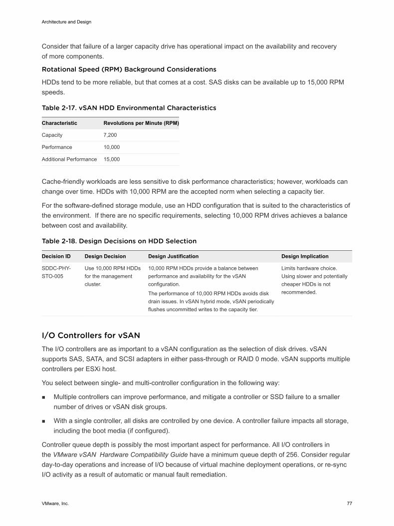
Consider that failure of a larger capacity drive has operational impact on the availability and recoveryof more components.
Rotational Speed (RPM) Background Considerations
HDDs tend to be more reliable, but that comes at a cost. SAS disks can be available up to 15,000 RPMspeeds.
Table 2-17. vSAN HDD Environmental Characteristics
Characteristic Revolutions per Minute (RPM)
Capacity 7,200
Performance 10,000
Additional Performance 15,000
Cache-friendly workloads are less sensitive to disk performance characteristics; however, workloads canchange over time. HDDs with 10,000 RPM are the accepted norm when selecting a capacity tier.
For the software-defined storage module, use an HDD configuration that is suited to the characteristics ofthe environment. If there are no specific requirements, selecting 10,000 RPM drives achieves a balancebetween cost and availability.
Table 2-18. Design Decisions on HDD Selection
Decision ID Design Decision Design Justification Design Implication
SDDC-PHY-STO-005
Use 10,000 RPM HDDsfor the managementcluster.
10,000 RPM HDDs provide a balance betweenperformance and availability for the vSANconfiguration.
The performance of 10,000 RPM HDDs avoids diskdrain issues. In vSAN hybrid mode, vSAN periodicallyflushes uncommitted writes to the capacity tier.
Limits hardware choice.Using slower and potentiallycheaper HDDs is notrecommended.
I/O Controllers for vSANThe I/O controllers are as important to a vSAN configuration as the selection of disk drives. vSANsupports SAS, SATA, and SCSI adapters in either pass-through or RAID 0 mode. vSAN supports multiplecontrollers per ESXi host.
You select between single- and multi-controller configuration in the following way:
n Multiple controllers can improve performance, and mitigate a controller or SSD failure to a smallernumber of drives or vSAN disk groups.
n With a single controller, all disks are controlled by one device. A controller failure impacts all storage,including the boot media (if configured).
Controller queue depth is possibly the most important aspect for performance. All I/O controllers inthe VMware vSAN Hardware Compatibility Guide have a minimum queue depth of 256. Consider regularday-to-day operations and increase of I/O because of virtual machine deployment operations, or re-syncI/O activity as a result of automatic or manual fault remediation.
Architecture and Design
VMware, Inc. 77
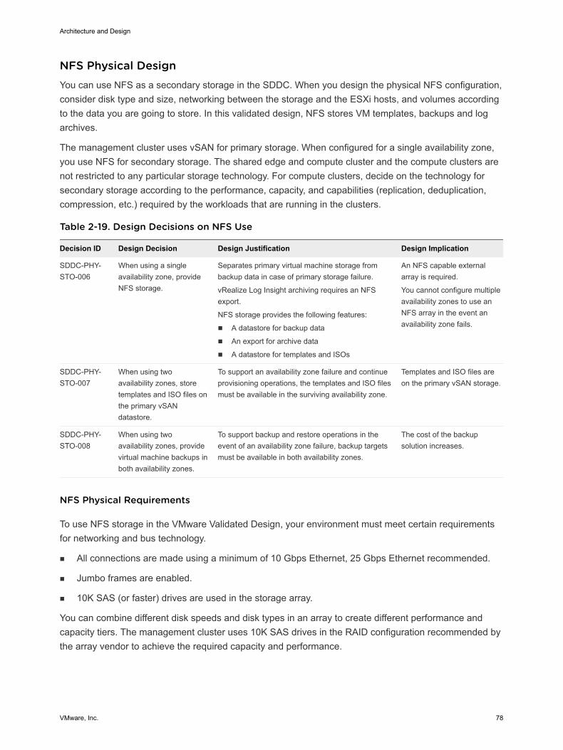
NFS Physical Design You can use NFS as a secondary storage in the SDDC. When you design the physical NFS configuration,consider disk type and size, networking between the storage and the ESXi hosts, and volumes accordingto the data you are going to store. In this validated design, NFS stores VM templates, backups and logarchives.
The management cluster uses vSAN for primary storage. When configured for a single availability zone,you use NFS for secondary storage. The shared edge and compute cluster and the compute clusters arenot restricted to any particular storage technology. For compute clusters, decide on the technology forsecondary storage according to the performance, capacity, and capabilities (replication, deduplication,compression, etc.) required by the workloads that are running in the clusters.
Table 2-19. Design Decisions on NFS Use
Decision ID Design Decision Design Justification Design Implication
SDDC-PHY-STO-006
When using a singleavailability zone, provideNFS storage.
Separates primary virtual machine storage frombackup data in case of primary storage failure.
vRealize Log Insight archiving requires an NFSexport.
NFS storage provides the following features:
n A datastore for backup data
n An export for archive data
n A datastore for templates and ISOs
An NFS capable externalarray is required.
You cannot configure multipleavailability zones to use anNFS array in the event anavailability zone fails.
SDDC-PHY-STO-007
When using twoavailability zones, storetemplates and ISO files onthe primary vSANdatastore.
To support an availability zone failure and continueprovisioning operations, the templates and ISO filesmust be available in the surviving availability zone.
Templates and ISO files areon the primary vSAN storage.
SDDC-PHY-STO-008
When using twoavailability zones, providevirtual machine backups inboth availability zones.
To support backup and restore operations in theevent of an availability zone failure, backup targetsmust be available in both availability zones.
The cost of the backupsolution increases.
NFS Physical Requirements
To use NFS storage in the VMware Validated Design, your environment must meet certain requirementsfor networking and bus technology.
n All connections are made using a minimum of 10 Gbps Ethernet, 25 Gbps Ethernet recommended.
n Jumbo frames are enabled.
n 10K SAS (or faster) drives are used in the storage array.
You can combine different disk speeds and disk types in an array to create different performance andcapacity tiers. The management cluster uses 10K SAS drives in the RAID configuration recommended bythe array vendor to achieve the required capacity and performance.
Architecture and Design
VMware, Inc. 78
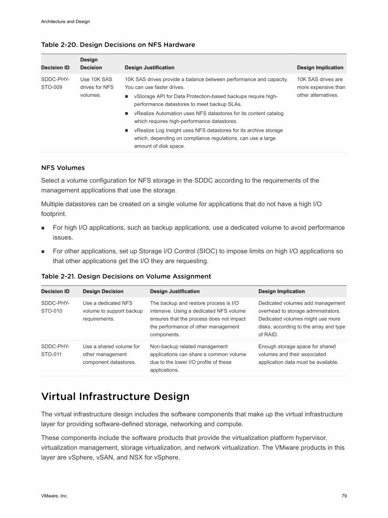
Table 2-20. Design Decisions on NFS Hardware
Decision IDDesignDecision Design Justification Design Implication
SDDC-PHY-STO-009
Use 10K SASdrives for NFSvolumes.
10K SAS drives provide a balance between performance and capacity.You can use faster drives.
n vStorage API for Data Protection-based backups require high-performance datastores to meet backup SLAs.
n vRealize Automation uses NFS datastores for its content catalogwhich requires high-performance datastores.
n vRealize Log Insight uses NFS datastores for its archive storagewhich, depending on compliance regulations, can use a largeamount of disk space.
10K SAS drives aremore expensive thanother alternatives.
NFS Volumes
Select a volume configuration for NFS storage in the SDDC according to the requirements of themanagement applications that use the storage.
Multiple datastores can be created on a single volume for applications that do not have a high I/Ofootprint.
n For high I/O applications, such as backup applications, use a dedicated volume to avoid performanceissues.
n For other applications, set up Storage I/O Control (SIOC) to impose limits on high I/O applications sothat other applications get the I/O they are requesting.
Table 2-21. Design Decisions on Volume Assignment
Decision ID Design Decision Design Justification Design Implication
SDDC-PHY-STO-010
Use a dedicated NFSvolume to support backuprequirements.
The backup and restore process is I/Ointensive. Using a dedicated NFS volumeensures that the process does not impactthe performance of other managementcomponents.
Dedicated volumes add managementoverhead to storage administrators.Dedicated volumes might use moredisks, according to the array and typeof RAID.
SDDC-PHY-STO-011
Use a shared volume forother managementcomponent datastores.
Non-backup related managementapplications can share a common volumedue to the lower I/O profile of theseapplications.
Enough storage space for sharedvolumes and their associatedapplication data must be available.
Virtual Infrastructure Design The virtual infrastructure design includes the software components that make up the virtual infrastructurelayer for providing software-defined storage, networking and compute.
These components include the software products that provide the virtualization platform hypervisor,virtualization management, storage virtualization, and network virtualization. The VMware products in thislayer are vSphere, vSAN, and NSX for vSphere.
Architecture and Design
VMware, Inc. 79
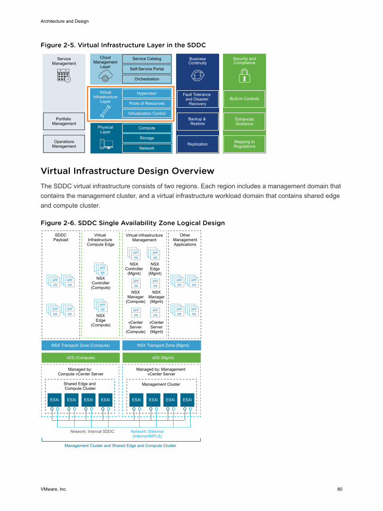
Figure 2-5. Virtual Infrastructure Layer in the SDDC
ServiceManagement
Portfolio Management
OperationsManagement
CloudManagement
Layer
Service Catalog
Self-Service Portal
Orchestration
BusinessContinuity
Fault Tolerance and Disaster
Recovery
Backup & Restore
Hypervisor
Pools of Resources
Virtualization Control
VirtualInfrastructure
Layer
Compute
Storage
Network
PhysicalLayer
Replication
Security and Compliance
Mapping to Regulations
Enhanced Guidance
Built-In Controls
Virtual Infrastructure Design OverviewThe SDDC virtual infrastructure consists of two regions. Each region includes a management domain thatcontains the management cluster, and a virtual infrastructure workload domain that contains shared edgeand compute cluster.
Figure 2-6. SDDC Single Availability Zone Logical Design
APP
OSAPP
OS
APP
OSAPP
OS
APP
OSAPP
OS
APP
OSAPP
OS
APP
OS
APP
OS
APP
OSAPP
OS
APP
OSAPP
OS
APP
OSAPP
OS
Virtual InfrastructureManagement
NSXController
(Mgmt)
OtherManagementApplications
NSXEdge
(Mgmt)
NSXManager(Mgmt)
NSXManager
(Compute)
NSXEdge
(Compute)
NSXController(Compute)
ESXi ESXi ESXi ESXi ESXi ESXi
SDDCPayload
Virtual Infrastructure Compute Edge
NSX Transport Zone (Compute)
vDS (Compute) vDS (Mgmt)
NSX Transport Zone (Mgmt)
Shared Edge and Compute Cluster
Management Cluster
Managed by: Compute vCenter Server
Managed by: Management vCenter Server
Network: External(Internet/MPLS)
Network: Internal SDDC
Management Cluster and Shared Edge and Compute Cluster
vCenterServer(Mgmt)
vCenterServer
(Compute)
ESXi ESXi
Architecture and Design
VMware, Inc. 80
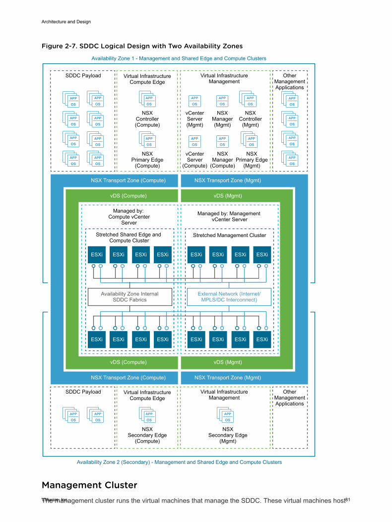
Figure 2-7. SDDC Logical Design with Two Availability Zones
APP
OS
APP
OSAPP
OSAPP
OS
APP
OSAPP
OS
APP
OS
APP
OS
APP
OSAPP
OS
APP
OS
APP
OS
APP
OS
APP
OSAPP
OS
APP
OSAPP
OS
APP
OS
APP
OS
APP
OS
APP
OSAPP
OSAPP
OSAPP
OS
ESXi ESXi
Virtual InfrastructureCompute Edge
NSXPrimary Edge
(Compute)
NSXController(Compute)
ESXi
SDDC Payload
NSX Transport Zone (Compute)
vDS (Compute)
Stretched Shared Edge and Compute Cluster
Stretched Management Cluster
Managed by: Compute vCenter
Server
Managed by: Management vCenter Server
External Network (Internet/MPLS/DC Interconnect)
Availability Zone InternalSDDC Fabrics
Availability Zone 1 - Management and Shared Edge and Compute Clusters
ESXi
Virtual InfrastructureManagement
NSXController
(Mgmt)
NSXPrimary Edge
(Mgmt)
NSXManager(Mgmt)
NSXManager
(Compute)
vCenterServer(Mgmt)
vCenterServer
(Compute)
Availability Zone 2 (Secondary) - Management and Shared Edge and Compute Clusters
OtherManagementApplications
ESXiESXi ESXiESXi
ESXiESXi ESXiESXiESXiESXi ESXiESXi
NSX Transport Zone (Compute)
vDS (Compute)
NSX Transport Zone (Mgmt)
vDS (Mgmt)
NSX Transport Zone (Mgmt)
vDS (Mgmt)
Virtual InfrastructureCompute Edge
NSXSecondary Edge
(Compute)
SDDC Payload Virtual InfrastructureManagement
NSXSecondary Edge
(Mgmt)
OtherManagementApplications
Management ClusterThe management cluster runs the virtual machines that manage the SDDC. These virtual machines host
Architecture and Design
VMware, Inc. 81
vCenter Server, NSX Manager, NSX Controllers, vRealize Lifecycle Manager, vRealize OperationsManager, vRealize Log Insight, vRealize Automation, Site Recovery Manager and other sharedmanagement components. All management, monitoring, and infrastructure services are provisioned to avSphere cluster which provides high availability for these critical services. Permissions on themanagement cluster limit access to only administrators. In this way, you protect the virtual machinesrunning the management, monitoring, and infrastructure services.
Shared Edge and Compute ClusterThe virtual infrastructure design uses a shared edge and compute cluster. The shared cluster combinesthe characteristics of typical edge and compute clusters into a single cluster. It is possible to separatethese in the future if required.
This cluster provides the following main functions:
n Supports on-ramp and off-ramp connectivity to physical networks
n Connects with VLANs in the physical world
n Hosts the SDDC tenant virtual machines
The shared edge and compute cluster connects the virtual networks (overlay networks) provided by NSXfor vSphere and the external networks. An SDDC can mix different types of compute-only clusters andprovide separate compute pools for different types of SLAs.
ESXi Design For the design of the configuration of the ESXi hosts, consider boot options, user access, and the virtualmachine swap configuration.
ESXi Hardware RequirementsFor the ESXi hardware requirements, see Physical Design Fundamentals .
ESXi Manual Install and Boot OptionsYou can install or boot ESXi from the following storage systems:
SATA disk drives SATA disk drives connected behind supported SAS controllers or supportedon-board SATA controllers.
Serial-attached SCSI(SAS) disk drives
Supported for ESXi installation
SAN Dedicated SAN disk on Fibre Channel or iSCSI.
USB and SD Supported for ESXi installation. Use a 16 GB or larger device.
FCoE Dedicated FCoE LUN. You can use a VMware software FCoE adapter anda network adapter with FCoE capabilities. A dedicated FCoE HBA is notrequired.
Architecture and Design
VMware, Inc. 82
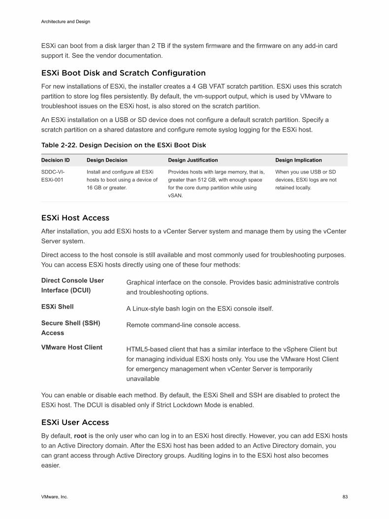
ESXi can boot from a disk larger than 2 TB if the system firmware and the firmware on any add-in cardsupport it. See the vendor documentation.
ESXi Boot Disk and Scratch ConfigurationFor new installations of ESXi, the installer creates a 4 GB VFAT scratch partition. ESXi uses this scratchpartition to store log files persistently. By default, the vm-support output, which is used by VMware totroubleshoot issues on the ESXi host, is also stored on the scratch partition.
An ESXi installation on a USB or SD device does not configure a default scratch partition. Specify ascratch partition on a shared datastore and configure remote syslog logging for the ESXi host.
Table 2-22. Design Decision on the ESXi Boot Disk
Decision ID Design Decision Design Justification Design Implication
SDDC-VI-ESXi-001
Install and configure all ESXihosts to boot using a device of16 GB or greater.
Provides hosts with large memory, that is,greater than 512 GB, with enough spacefor the core dump partition while usingvSAN.
When you use USB or SDdevices, ESXi logs are notretained locally.
ESXi Host AccessAfter installation, you add ESXi hosts to a vCenter Server system and manage them by using the vCenterServer system.
Direct access to the host console is still available and most commonly used for troubleshooting purposes.You can access ESXi hosts directly using one of these four methods:
Direct Console UserInterface (DCUI)
Graphical interface on the console. Provides basic administrative controlsand troubleshooting options.
ESXi Shell A Linux-style bash login on the ESXi console itself.
Secure Shell (SSH)Access
Remote command-line console access.
VMware Host Client HTML5-based client that has a similar interface to the vSphere Client butfor managing individual ESXi hosts only. You use the VMware Host Clientfor emergency management when vCenter Server is temporarilyunavailable
You can enable or disable each method. By default, the ESXi Shell and SSH are disabled to protect theESXi host. The DCUI is disabled only if Strict Lockdown Mode is enabled.
ESXi User AccessBy default, root is the only user who can log in to an ESXi host directly. However, you can add ESXi hoststo an Active Directory domain. After the ESXi host has been added to an Active Directory domain, youcan grant access through Active Directory groups. Auditing logins in to the ESXi host also becomeseasier.
Architecture and Design
VMware, Inc. 83
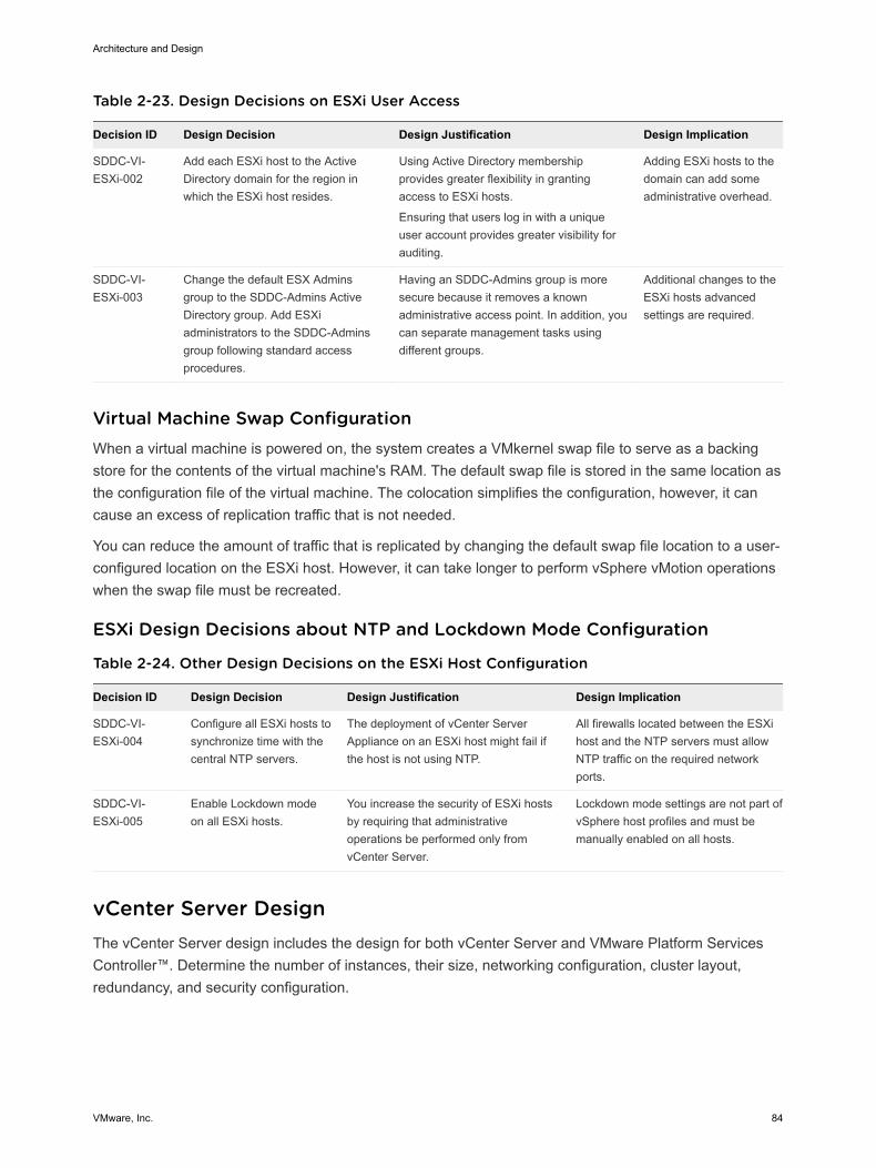
Table 2-23. Design Decisions on ESXi User Access
Decision ID Design Decision Design Justification Design Implication
SDDC-VI-ESXi-002
Add each ESXi host to the ActiveDirectory domain for the region inwhich the ESXi host resides.
Using Active Directory membershipprovides greater flexibility in grantingaccess to ESXi hosts.
Ensuring that users log in with a uniqueuser account provides greater visibility forauditing.
Adding ESXi hosts to thedomain can add someadministrative overhead.
SDDC-VI-ESXi-003
Change the default ESX Adminsgroup to the SDDC-Admins ActiveDirectory group. Add ESXiadministrators to the SDDC-Adminsgroup following standard accessprocedures.
Having an SDDC-Admins group is moresecure because it removes a knownadministrative access point. In addition, youcan separate management tasks usingdifferent groups.
Additional changes to theESXi hosts advancedsettings are required.
Virtual Machine Swap ConfigurationWhen a virtual machine is powered on, the system creates a VMkernel swap file to serve as a backingstore for the contents of the virtual machine's RAM. The default swap file is stored in the same location asthe configuration file of the virtual machine. The colocation simplifies the configuration, however, it cancause an excess of replication traffic that is not needed.
You can reduce the amount of traffic that is replicated by changing the default swap file location to a user-configured location on the ESXi host. However, it can take longer to perform vSphere vMotion operationswhen the swap file must be recreated.
ESXi Design Decisions about NTP and Lockdown Mode Configuration
Table 2-24. Other Design Decisions on the ESXi Host Configuration
Decision ID Design Decision Design Justification Design Implication
SDDC-VI-ESXi-004
Configure all ESXi hosts tosynchronize time with thecentral NTP servers.
The deployment of vCenter ServerAppliance on an ESXi host might fail ifthe host is not using NTP.
All firewalls located between the ESXihost and the NTP servers must allowNTP traffic on the required networkports.
SDDC-VI-ESXi-005
Enable Lockdown modeon all ESXi hosts.
You increase the security of ESXi hostsby requiring that administrativeoperations be performed only fromvCenter Server.
Lockdown mode settings are not part ofvSphere host profiles and must bemanually enabled on all hosts.
vCenter Server Design The vCenter Server design includes the design for both vCenter Server and VMware Platform ServicesController™. Determine the number of instances, their size, networking configuration, cluster layout,redundancy, and security configuration.
Architecture and Design
VMware, Inc. 84
A Platform Services Controller instance groups a set of infrastructure services including vCenter SingleSign-On, License service, Lookup Service, and VMware Certificate Authority (VMCA).
n vCenter Server Deployment
A vCenter Server deployment can consist of one or several vCenter Server and Platform ServicesController instances according to the scale, number of virtual machines and continuity requirementsfor your environment.
n vCenter Server Networking
As specified in the physical networking design, all vCenter Server systems must use static IPaddresses and host names. The IP addresses must have valid internal DNS registration includingreverse name resolution.
n vCenter Server Redundancy
Protecting the vCenter Server system is important because it is the central point of management andmonitoring for the SDDC. You protect vCenter Server according to the maximum downtime toleratedand whether failover automation is required.
n vCenter Server Appliance Sizing
You size resources and storage for the Management vCenter Server Appliance and the ComputevCenter Server Appliance according to the expected number of management virtual machines in theSDDC.
n vSphere Cluster Design
The cluster design must consider the workloads that the cluster handles. Different cluster types inthis design have different characteristics.
n vCenter Server Customization
vCenter Server supports a set of customization options, including monitoring, virtual machine faulttolerance, and so on.
n Use of TLS Certificates in vCenter Server
By default, vSphere uses TLS/SSL certificates that are signed by VMCA (VMware CertificateAuthority). These certificates are not trusted by end-user devices or browsers.
vCenter Server Deployment A vCenter Server deployment can consist of one or several vCenter Server and Platform ServicesController instances according to the scale, number of virtual machines and continuity requirements foryour environment.
You also determine the type of installation and the topology of the vCenter Server and Platform ServicesController instances.
Architecture and Design
VMware, Inc. 85
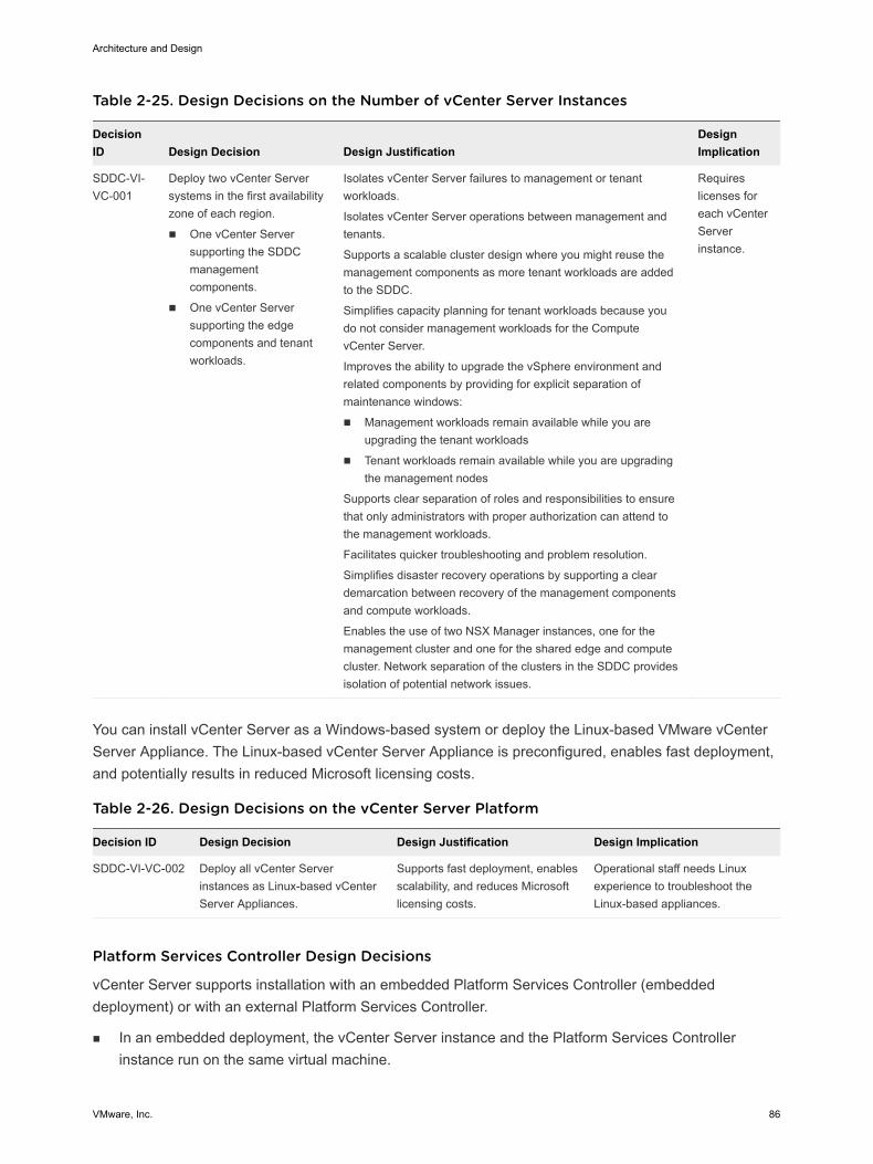
Table 2-25. Design Decisions on the Number of vCenter Server Instances
DecisionID Design Decision Design Justification
DesignImplication
SDDC-VI-VC-001
Deploy two vCenter Serversystems in the first availabilityzone of each region.
n One vCenter Serversupporting the SDDCmanagementcomponents.
n One vCenter Serversupporting the edgecomponents and tenantworkloads.
Isolates vCenter Server failures to management or tenantworkloads.
Isolates vCenter Server operations between management andtenants.
Supports a scalable cluster design where you might reuse themanagement components as more tenant workloads are addedto the SDDC.
Simplifies capacity planning for tenant workloads because youdo not consider management workloads for the ComputevCenter Server.
Improves the ability to upgrade the vSphere environment andrelated components by providing for explicit separation ofmaintenance windows:
n Management workloads remain available while you areupgrading the tenant workloads
n Tenant workloads remain available while you are upgradingthe management nodes
Supports clear separation of roles and responsibilities to ensurethat only administrators with proper authorization can attend tothe management workloads.
Facilitates quicker troubleshooting and problem resolution.
Simplifies disaster recovery operations by supporting a cleardemarcation between recovery of the management componentsand compute workloads.
Enables the use of two NSX Manager instances, one for themanagement cluster and one for the shared edge and computecluster. Network separation of the clusters in the SDDC providesisolation of potential network issues.
Requireslicenses foreach vCenterServerinstance.
You can install vCenter Server as a Windows-based system or deploy the Linux-based VMware vCenterServer Appliance. The Linux-based vCenter Server Appliance is preconfigured, enables fast deployment,and potentially results in reduced Microsoft licensing costs.
Table 2-26. Design Decisions on the vCenter Server Platform
Decision ID Design Decision Design Justification Design Implication
SDDC-VI-VC-002 Deploy all vCenter Serverinstances as Linux-based vCenterServer Appliances.
Supports fast deployment, enablesscalability, and reduces Microsoftlicensing costs.
Operational staff needs Linuxexperience to troubleshoot theLinux-based appliances.
Platform Services Controller Design Decisions
vCenter Server supports installation with an embedded Platform Services Controller (embeddeddeployment) or with an external Platform Services Controller.
n In an embedded deployment, the vCenter Server instance and the Platform Services Controllerinstance run on the same virtual machine.
Architecture and Design
VMware, Inc. 86
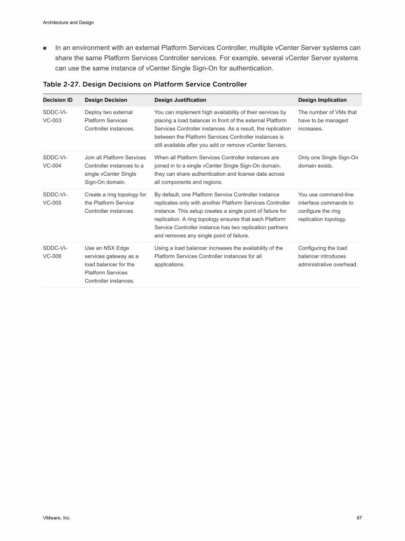
n In an environment with an external Platform Services Controller, multiple vCenter Server systems canshare the same Platform Services Controller services. For example, several vCenter Server systemscan use the same instance of vCenter Single Sign-On for authentication.
Table 2-27. Design Decisions on Platform Service Controller
Decision ID Design Decision Design Justification Design Implication
SDDC-VI-VC-003
Deploy two externalPlatform ServicesController instances.
You can implement high availability of their services byplacing a load balancer in front of the external PlatformServices Controller instances. As a result, the replicationbetween the Platform Services Controller instances isstill available after you add or remove vCenter Servers.
The number of VMs thathave to be managedincreases.
SDDC-VI-VC-004
Join all Platform ServicesController instances to asingle vCenter SingleSign-On domain.
When all Platform Services Controller instances arejoined in to a single vCenter Single Sign-On domain,they can share authentication and license data acrossall components and regions.
Only one Single Sign-Ondomain exists.
SDDC-VI-VC-005
Create a ring topology forthe Platform ServiceController instances.
By default, one Platform Service Controller instancereplicates only with another Platform Services Controllerinstance. This setup creates a single point of failure forreplication. A ring topology ensures that each PlatformService Controller instance has two replication partnersand removes any single point of failure.
You use command-lineinterface commands toconfigure the ringreplication topology.
SDDC-VI-VC-006
Use an NSX Edgeservices gateway as aload balancer for thePlatform ServicesController instances.
Using a load balancer increases the availability of thePlatform Services Controller instances for allapplications.
Configuring the loadbalancer introducesadministrative overhead.
Architecture and Design
VMware, Inc. 87
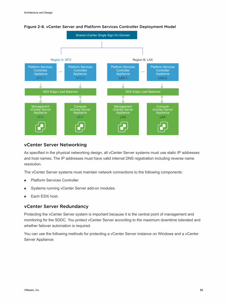
Figure 2-8. vCenter Server and Platform Services Controller Deployment Model
Region A: SFO Region B: LAX
Platform Services ControllerAppliance
SFO-1
Management vCenter Server
Appliance
Shared vCenter Single Sign-On Domain
Platform ServicesControllerAppliance
SFO-2
NSX Edge Load Balancer NSX Edge Load Balancer
ComputevCenter Server
Appliance
Platform ServicesControllerAppliance
LAX-2
ComputevCenter Server
Appliance
Platform ServicesControllerAppliance
LAX-1
Management vCenter Server
Appliance LAX LAXSFO SFO
vCenter Server Networking As specified in the physical networking design, all vCenter Server systems must use static IP addressesand host names. The IP addresses must have valid internal DNS registration including reverse nameresolution.
The vCenter Server systems must maintain network connections to the following components:
n Platform Services Controller
n Systems running vCenter Server add-on modules.
n Each ESXi host.
vCenter Server Redundancy Protecting the vCenter Server system is important because it is the central point of management andmonitoring for the SDDC. You protect vCenter Server according to the maximum downtime tolerated andwhether failover automation is required.
You can use the following methods for protecting a vCenter Server instance on Windows and a vCenterServer Appliance:
Architecture and Design
VMware, Inc. 88
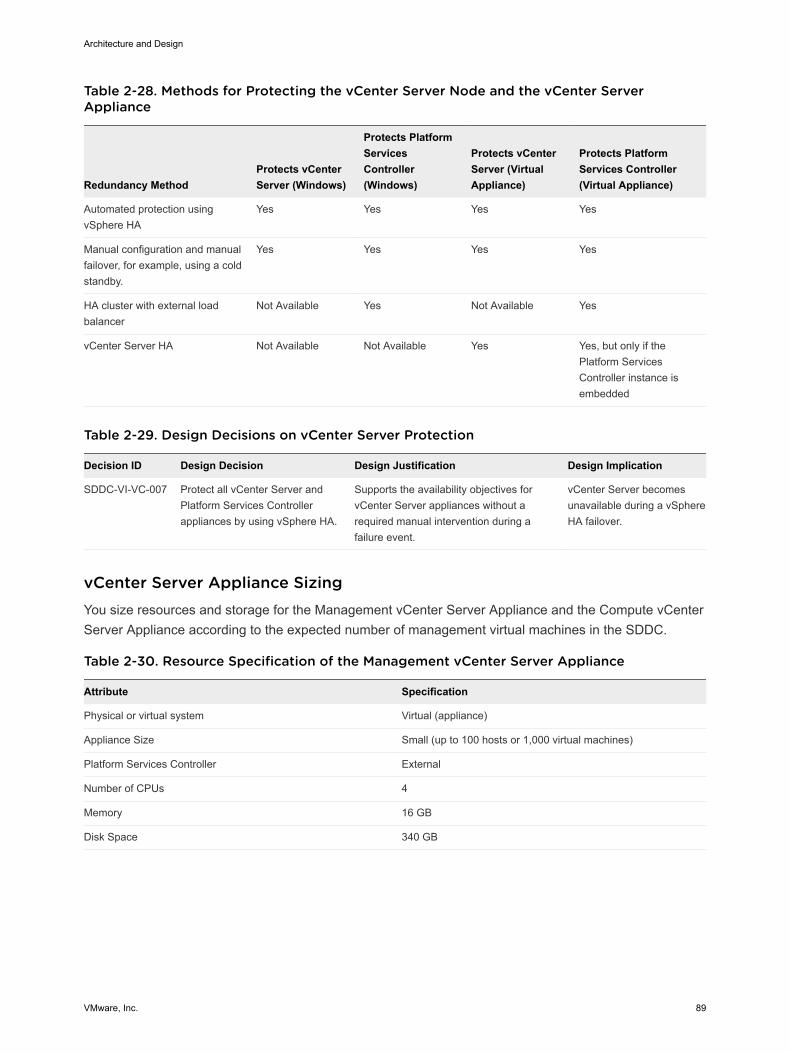
Table 2-28. Methods for Protecting the vCenter Server Node and the vCenter ServerAppliance
Redundancy MethodProtects vCenterServer (Windows)
Protects PlatformServicesController(Windows)
Protects vCenterServer (VirtualAppliance)
Protects PlatformServices Controller(Virtual Appliance)
Automated protection usingvSphere HA
Yes Yes Yes Yes
Manual configuration and manualfailover, for example, using a coldstandby.
Yes Yes Yes Yes
HA cluster with external loadbalancer
Not Available Yes Not Available Yes
vCenter Server HA Not Available Not Available Yes Yes, but only if thePlatform ServicesController instance isembedded
Table 2-29. Design Decisions on vCenter Server Protection
Decision ID Design Decision Design Justification Design Implication
SDDC-VI-VC-007 Protect all vCenter Server andPlatform Services Controllerappliances by using vSphere HA.
Supports the availability objectives forvCenter Server appliances without arequired manual intervention during afailure event.
vCenter Server becomesunavailable during a vSphereHA failover.
vCenter Server Appliance Sizing You size resources and storage for the Management vCenter Server Appliance and the Compute vCenterServer Appliance according to the expected number of management virtual machines in the SDDC.
Table 2-30. Resource Specification of the Management vCenter Server Appliance
Attribute Specification
Physical or virtual system Virtual (appliance)
Appliance Size Small (up to 100 hosts or 1,000 virtual machines)
Platform Services Controller External
Number of CPUs 4
Memory 16 GB
Disk Space 340 GB
Architecture and Design
VMware, Inc. 89
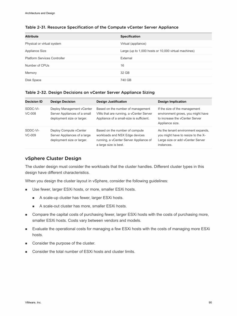
Table 2-31. Resource Specification of the Compute vCenter Server Appliance
Attribute Specification
Physical or virtual system Virtual (appliance)
Appliance Size Large (up to 1,000 hosts or 10,000 virtual machines)
Platform Services Controller External
Number of CPUs 16
Memory 32 GB
Disk Space 740 GB
Table 2-32. Design Decisions on vCenter Server Appliance Sizing
Decision ID Design Decision Design Justification Design Implication
SDDC-VI-VC-008
Deploy Management vCenterServer Appliances of a smalldeployment size or larger.
Based on the number of managementVMs that are running, a vCenter ServerAppliance of a small-size is sufficient.
If the size of the managementenvironment grows, you might haveto increase the vCenter ServerAppliance size.
SDDC-VI-VC-009
Deploy Compute vCenterServer Appliances of a largedeployment size or larger.
Based on the number of computeworkloads and NSX Edge devicesrunning, a vCenter Server Appliance ofa large size is best.
As the tenant environment expands,you might have to resize to the X-Large size or add vCenter Serverinstances.
vSphere Cluster Design The cluster design must consider the workloads that the cluster handles. Different cluster types in thisdesign have different characteristics.
When you design the cluster layout in vSphere, consider the following guidelines:
n Use fewer, larger ESXi hosts, or more, smaller ESXi hosts.
n A scale-up cluster has fewer, larger ESXi hosts.
n A scale-out cluster has more, smaller ESXi hosts.
n Compare the capital costs of purchasing fewer, larger ESXi hosts with the costs of purchasing more,smaller ESXi hosts. Costs vary between vendors and models.
n Evaluate the operational costs for managing a few ESXi hosts with the costs of managing more ESXihosts.
n Consider the purpose of the cluster.
n Consider the total number of ESXi hosts and cluster limits.
Architecture and Design
VMware, Inc. 90
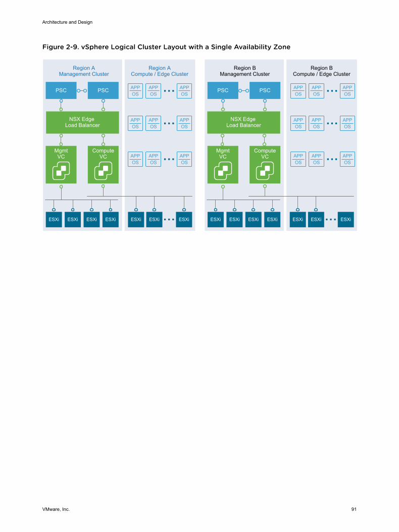
Figure 2-9. vSphere Logical Cluster Layout with a Single Availability Zone
APPOS
APPOS
APPOS
APPOS
APPOS
APPOS
APPOS
APPOS
APPOS
APPOS
APPOS
APPOS
APPOS
APPOS
APPOS
APPOS
APPOS
APPOS
MgmtVC
Region AManagement Cluster
ESXi ESXi ESXi ESXi ESXi ESXi ESXi
Region ACompute / Edge Cluster
Region BManagement Cluster
Region BCompute / Edge Cluster
PSC
NSX Edge Load Balancer
NSX Edge Load Balancer
ComputeVC
PSC
MgmtVC
ESXi ESXi ESXi ESXi ESXi ESXi ESXi
PSC
ComputeVC
PSC
Architecture and Design
VMware, Inc. 91
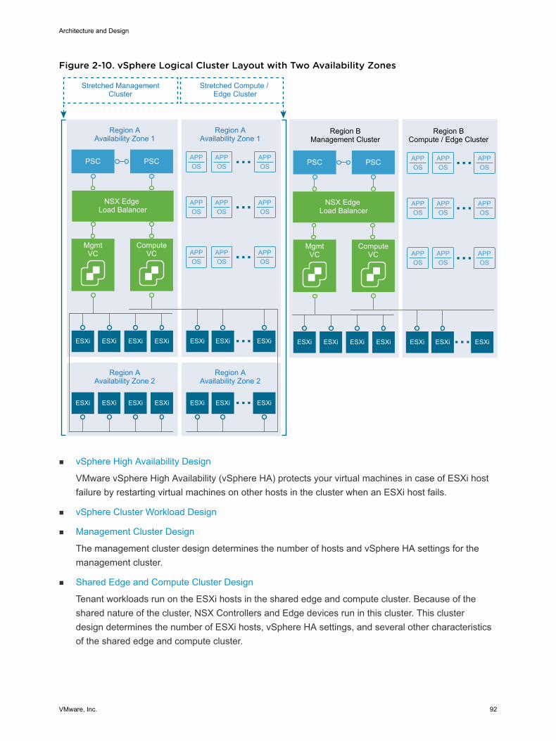
Figure 2-10. vSphere Logical Cluster Layout with Two Availability Zones
APPOS
APPOS
APPOS
APPOS
APPOS
APPOS
APPOS
APPOS
APPOS
APPOS
APPOS
APPOS
APPOS
APPOS
APPOS
APPOS
APPOS
APPOS
MgmtVC
Region AAvailability Zone 1
ESXi ESXi ESXi ESXi ESXi ESXi ESXi
Region AAvailability Zone 1
Region BManagement Cluster
Region BCompute / Edge Cluster
PSC
NSX Edge Load Balancer
NSX Edge Load Balancer
ComputeVC
PSC
MgmtVC
ESXi ESXi ESXi ESXi ESXi ESXi ESXi
PSC
ComputeVC
PSC
ESXi ESXi ESXi ESXi ESXi ESXi ESXi
Region AAvailability Zone 2
Region AAvailability Zone 2
Stretched ManagementCluster
Stretched Compute / Edge Cluster
n vSphere High Availability Design
VMware vSphere High Availability (vSphere HA) protects your virtual machines in case of ESXi hostfailure by restarting virtual machines on other hosts in the cluster when an ESXi host fails.
n vSphere Cluster Workload Design
n Management Cluster Design
The management cluster design determines the number of hosts and vSphere HA settings for themanagement cluster.
n Shared Edge and Compute Cluster Design
Tenant workloads run on the ESXi hosts in the shared edge and compute cluster. Because of theshared nature of the cluster, NSX Controllers and Edge devices run in this cluster. This clusterdesign determines the number of ESXi hosts, vSphere HA settings, and several other characteristicsof the shared edge and compute cluster.
Architecture and Design
VMware, Inc. 92
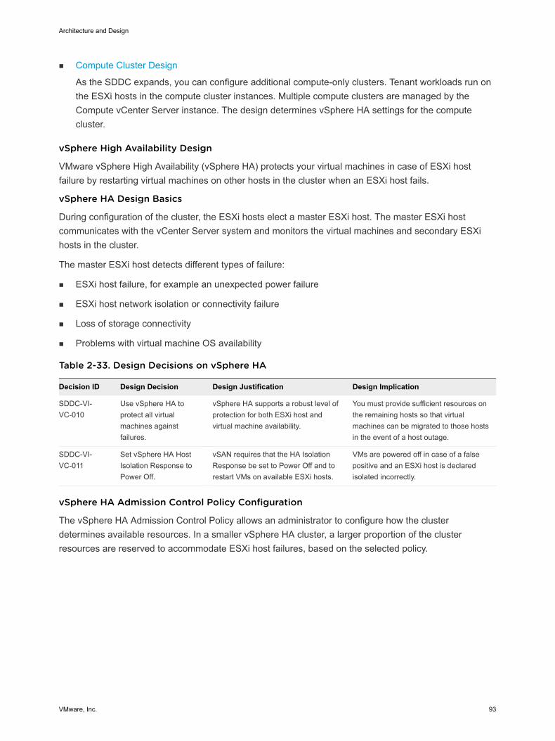
n Compute Cluster Design
As the SDDC expands, you can configure additional compute-only clusters. Tenant workloads run onthe ESXi hosts in the compute cluster instances. Multiple compute clusters are managed by theCompute vCenter Server instance. The design determines vSphere HA settings for the computecluster.
vSphere High Availability Design
VMware vSphere High Availability (vSphere HA) protects your virtual machines in case of ESXi hostfailure by restarting virtual machines on other hosts in the cluster when an ESXi host fails.
vSphere HA Design Basics
During configuration of the cluster, the ESXi hosts elect a master ESXi host. The master ESXi hostcommunicates with the vCenter Server system and monitors the virtual machines and secondary ESXihosts in the cluster.
The master ESXi host detects different types of failure:
n ESXi host failure, for example an unexpected power failure
n ESXi host network isolation or connectivity failure
n Loss of storage connectivity
n Problems with virtual machine OS availability
Table 2-33. Design Decisions on vSphere HA
Decision ID Design Decision Design Justification Design Implication
SDDC-VI-VC-010
Use vSphere HA toprotect all virtualmachines againstfailures.
vSphere HA supports a robust level ofprotection for both ESXi host andvirtual machine availability.
You must provide sufficient resources onthe remaining hosts so that virtualmachines can be migrated to those hostsin the event of a host outage.
SDDC-VI-VC-011
Set vSphere HA HostIsolation Response toPower Off.
vSAN requires that the HA IsolationResponse be set to Power Off and torestart VMs on available ESXi hosts.
VMs are powered off in case of a falsepositive and an ESXi host is declaredisolated incorrectly.
vSphere HA Admission Control Policy Configuration
The vSphere HA Admission Control Policy allows an administrator to configure how the clusterdetermines available resources. In a smaller vSphere HA cluster, a larger proportion of the clusterresources are reserved to accommodate ESXi host failures, based on the selected policy.
Architecture and Design
VMware, Inc. 93
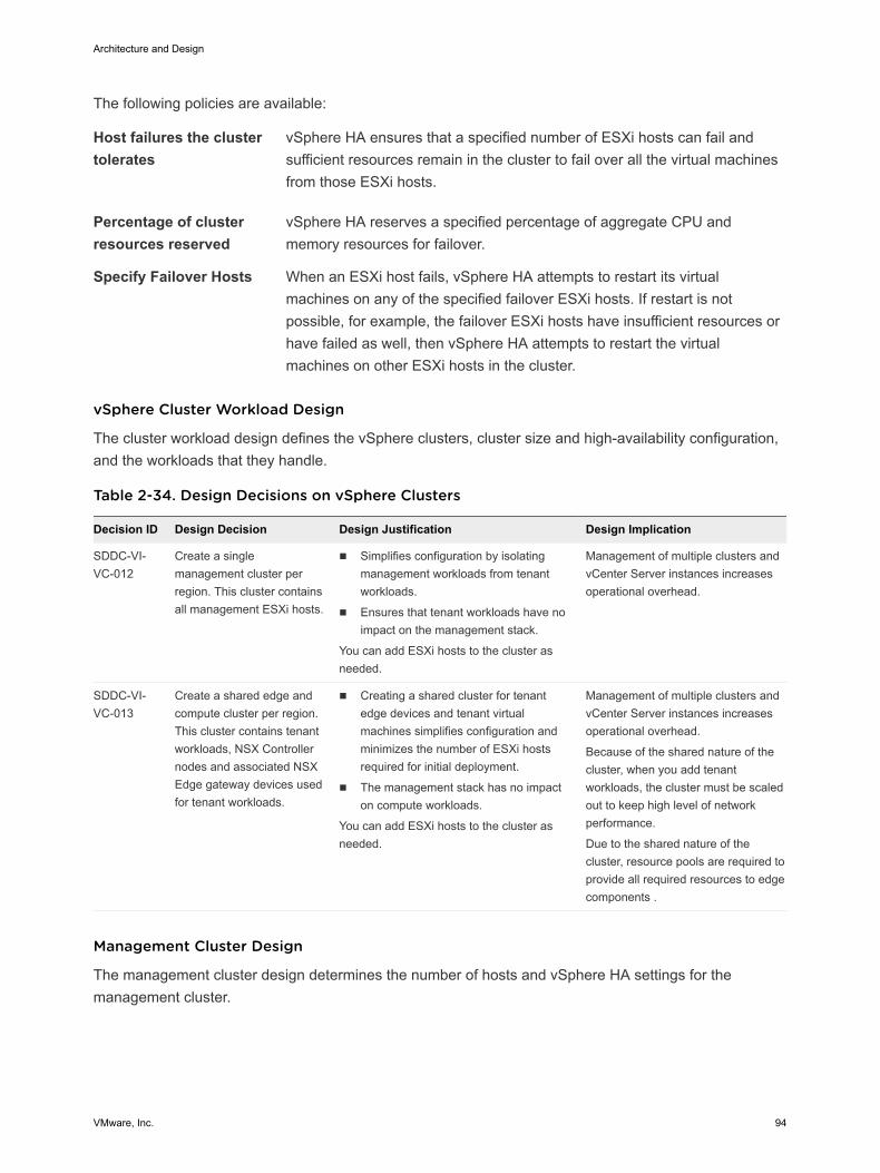
The following policies are available:
Host failures the clustertolerates
vSphere HA ensures that a specified number of ESXi hosts can fail andsufficient resources remain in the cluster to fail over all the virtual machinesfrom those ESXi hosts.
Percentage of clusterresources reserved
vSphere HA reserves a specified percentage of aggregate CPU andmemory resources for failover.
Specify Failover Hosts When an ESXi host fails, vSphere HA attempts to restart its virtualmachines on any of the specified failover ESXi hosts. If restart is notpossible, for example, the failover ESXi hosts have insufficient resources orhave failed as well, then vSphere HA attempts to restart the virtualmachines on other ESXi hosts in the cluster.
vSphere Cluster Workload Design
The cluster workload design defines the vSphere clusters, cluster size and high-availability configuration,and the workloads that they handle.
Table 2-34. Design Decisions on vSphere Clusters
Decision ID Design Decision Design Justification Design Implication
SDDC-VI-VC-012
Create a singlemanagement cluster perregion. This cluster containsall management ESXi hosts.
n Simplifies configuration by isolatingmanagement workloads from tenantworkloads.
n Ensures that tenant workloads have noimpact on the management stack.
You can add ESXi hosts to the cluster asneeded.
Management of multiple clusters andvCenter Server instances increasesoperational overhead.
SDDC-VI-VC-013
Create a shared edge andcompute cluster per region.This cluster contains tenantworkloads, NSX Controllernodes and associated NSXEdge gateway devices usedfor tenant workloads.
n Creating a shared cluster for tenantedge devices and tenant virtualmachines simplifies configuration andminimizes the number of ESXi hostsrequired for initial deployment.
n The management stack has no impacton compute workloads.
You can add ESXi hosts to the cluster asneeded.
Management of multiple clusters andvCenter Server instances increasesoperational overhead.
Because of the shared nature of thecluster, when you add tenantworkloads, the cluster must be scaledout to keep high level of networkperformance.
Due to the shared nature of thecluster, resource pools are required toprovide all required resources to edgecomponents .
Management Cluster Design
The management cluster design determines the number of hosts and vSphere HA settings for themanagement cluster.
Architecture and Design
VMware, Inc. 94
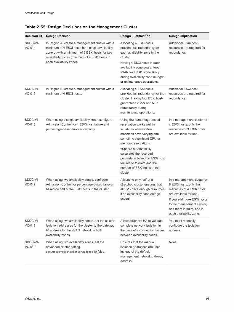
Table 2-35. Design Decisions on the Management Cluster
Decision ID Design Decision Design Justification Design Implication
SDDC-VI-VC-014
In Region A, create a management cluster with aminimum of 4 ESXi hosts for a single availabilityzone or with a minimum of 8 ESXi hosts for twoavailability zones (minimum of 4 ESXi hosts ineach availability zone).
Allocating 4 ESXi hostsprovides full redundancy foreach availability zone in thecluster.
Having 4 ESXi hosts in eachavailability zone guaranteesvSAN and NSX redundancyduring availability zone outagesor maintenance operations.
Additional ESXi hostresources are required forredundancy.
SDDC-VI-VC-015
In Region B, create a management cluster with aminimum of 4 ESXi hosts.
Allocating 4 ESXi hostsprovides full redundancy for thecluster. Having four ESXi hostsguarantees vSAN and NSXredundancy duringmaintenance operations.
Additional ESXi hostresources are required forredundancy.
SDDC-VI-VC-016
When using a single availability zone, configureAdmission Control for 1 ESXi host failure andpercentage-based failover capacity.
Using the percentage-basedreservation works well insituations where virtualmachines have varying andsometime significant CPU ormemory reservations.
vSphere automaticallycalculates the reservedpercentage based on ESXi hostfailures to tolerate and thenumber of ESXi hosts in thecluster.
In a management cluster of4 ESXi hosts, only theresources of 3 ESXi hostsare available for use.
SDDC-VI-VC-017
When using two availability zones, configureAdmission Control for percentage-based failoverbased on half of the ESXi hosts in the cluster.
Allocating only half of astretched cluster ensures thatall VMs have enough resourcesif an availability zone outageoccurs.
In a management cluster of8 ESXi hosts, only theresources of 4 ESXi hostsare available for use.
If you add more ESXi hoststo the management cluster,add them in pairs, one ineach availability zone.
SDDC-VI-VC-018
When using two availability zones, set the clusterisolation addresses for the cluster to the gatewayIP address for the vSAN network in bothavailability zones.
Allows vSphere HA to validatecomplete network isolation inthe case of a connection failurebetween availability zones.
You must manuallyconfigure the isolationaddress.
SDDC-VI-VC-019
When using two availability zones, set theadvanced cluster settingdas.usedefaultisolationaddress to false.
Ensures that the manualisolation addresses are usedinstead of the defaultmanagement network gatewayaddress.
None.
Architecture and Design
VMware, Inc. 95
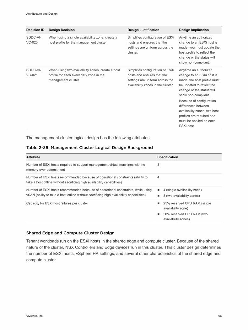
Decision ID Design Decision Design Justification Design Implication
SDDC-VI-VC-020
When using a single availability zone, create ahost profile for the management cluster.
Simplifies configuration of ESXihosts and ensures that thesettings are uniform across thecluster.
Anytime an authorizedchange to an ESXi host ismade, you must update thehost profile to reflect thechange or the status willshow non-compliant.
SDDC-VI-VC-021
When using two availability zones, create a hostprofile for each availability zone in themanagement cluster.
Simplifies configuration of ESXihosts and ensures that thesettings are uniform across theavailability zones in the cluster.
Anytime an authorizedchange to an ESXi host ismade, the host profile mustbe updated to reflect thechange or the status willshow non-compliant.
Because of configurationdifferences betweenavailability zones, two hostprofiles are required andmust be applied on eachESXi host.
The management cluster logical design has the following attributes:
Table 2-36. Management Cluster Logical Design Background
Attribute Specification
Number of ESXi hosts required to support management virtual machines with nomemory over commitment
3
Number of ESXi hosts recommended because of operational constraints (ability totake a host offline without sacrificing high availability capabilities)
4
Number of ESXi hosts recommended because of operational constraints, while usingvSAN (ability to take a host offline without sacrificing high availability capabilities) .
n 4 (single availability zone)
n 8 (two availability zones)
Capacity for ESXi host failures per cluster n 25% reserved CPU RAM (singleavailability zone)
n 50% reserved CPU RAM (twoavailability zones)
Shared Edge and Compute Cluster Design
Tenant workloads run on the ESXi hosts in the shared edge and compute cluster. Because of the sharednature of the cluster, NSX Controllers and Edge devices run in this cluster. This cluster design determinesthe number of ESXi hosts, vSphere HA settings, and several other characteristics of the shared edge andcompute cluster.
Architecture and Design
VMware, Inc. 96
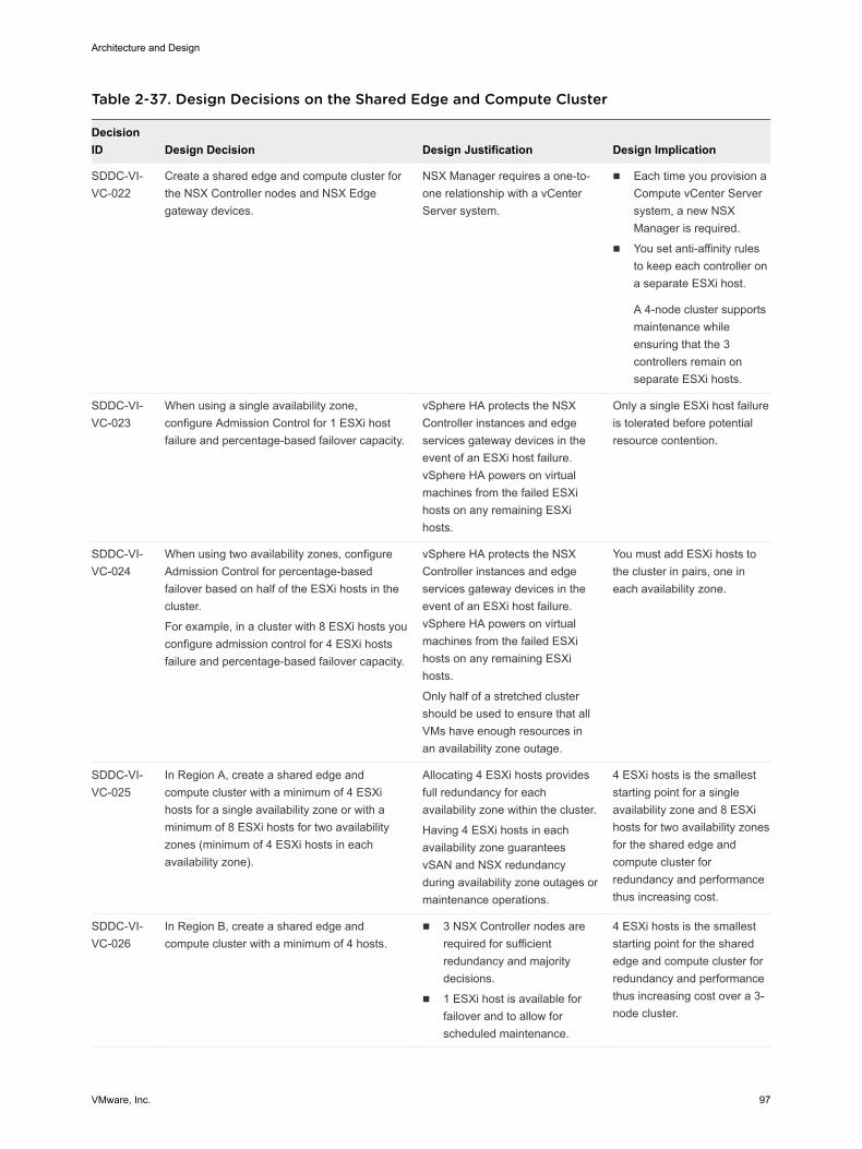
Table 2-37. Design Decisions on the Shared Edge and Compute Cluster
DecisionID Design Decision Design Justification Design Implication
SDDC-VI-VC-022
Create a shared edge and compute cluster forthe NSX Controller nodes and NSX Edgegateway devices.
NSX Manager requires a one-to-one relationship with a vCenterServer system.
n Each time you provision aCompute vCenter Serversystem, a new NSXManager is required.
n You set anti-affinity rulesto keep each controller ona separate ESXi host.
A 4-node cluster supportsmaintenance whileensuring that the 3controllers remain onseparate ESXi hosts.
SDDC-VI-VC-023
When using a single availability zone,configure Admission Control for 1 ESXi hostfailure and percentage-based failover capacity.
vSphere HA protects the NSXController instances and edgeservices gateway devices in theevent of an ESXi host failure.vSphere HA powers on virtualmachines from the failed ESXihosts on any remaining ESXihosts.
Only a single ESXi host failureis tolerated before potentialresource contention.
SDDC-VI-VC-024
When using two availability zones, configureAdmission Control for percentage-basedfailover based on half of the ESXi hosts in thecluster.
For example, in a cluster with 8 ESXi hosts youconfigure admission control for 4 ESXi hostsfailure and percentage-based failover capacity.
vSphere HA protects the NSXController instances and edgeservices gateway devices in theevent of an ESXi host failure.vSphere HA powers on virtualmachines from the failed ESXihosts on any remaining ESXihosts.
Only half of a stretched clustershould be used to ensure that allVMs have enough resources inan availability zone outage.
You must add ESXi hosts tothe cluster in pairs, one ineach availability zone.
SDDC-VI-VC-025
In Region A, create a shared edge andcompute cluster with a minimum of 4 ESXihosts for a single availability zone or with aminimum of 8 ESXi hosts for two availabilityzones (minimum of 4 ESXi hosts in eachavailability zone).
Allocating 4 ESXi hosts providesfull redundancy for eachavailability zone within the cluster.
Having 4 ESXi hosts in eachavailability zone guaranteesvSAN and NSX redundancyduring availability zone outages ormaintenance operations.
4 ESXi hosts is the smalleststarting point for a singleavailability zone and 8 ESXihosts for two availability zonesfor the shared edge andcompute cluster forredundancy and performancethus increasing cost.
SDDC-VI-VC-026
In Region B, create a shared edge andcompute cluster with a minimum of 4 hosts.
n 3 NSX Controller nodes arerequired for sufficientredundancy and majoritydecisions.
n 1 ESXi host is available forfailover and to allow forscheduled maintenance.
4 ESXi hosts is the smalleststarting point for the sharededge and compute cluster forredundancy and performancethus increasing cost over a 3-node cluster.
Architecture and Design
VMware, Inc. 97
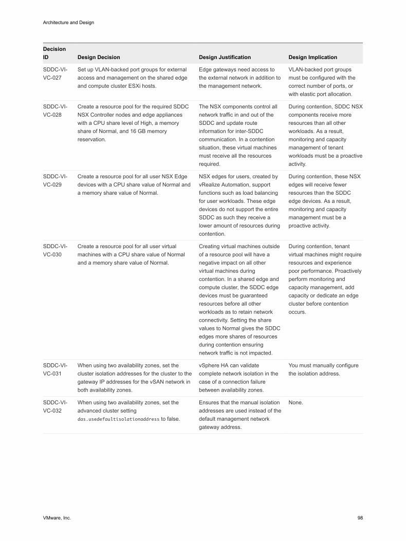
DecisionID Design Decision Design Justification Design Implication
SDDC-VI-VC-027
Set up VLAN-backed port groups for externalaccess and management on the shared edgeand compute cluster ESXi hosts.
Edge gateways need access tothe external network in addition tothe management network.
VLAN-backed port groupsmust be configured with thecorrect number of ports, orwith elastic port allocation.
SDDC-VI-VC-028
Create a resource pool for the required SDDCNSX Controller nodes and edge applianceswith a CPU share level of High, a memoryshare of Normal, and 16 GB memoryreservation.
The NSX components control allnetwork traffic in and out of theSDDC and update routeinformation for inter-SDDCcommunication. In a contentionsituation, these virtual machinesmust receive all the resourcesrequired.
During contention, SDDC NSXcomponents receive moreresources than all otherworkloads. As a result,monitoring and capacitymanagement of tenantworkloads must be a proactiveactivity.
SDDC-VI-VC-029
Create a resource pool for all user NSX Edgedevices with a CPU share value of Normal anda memory share value of Normal.
NSX edges for users, created byvRealize Automation, supportfunctions such as load balancingfor user workloads. These edgedevices do not support the entireSDDC as such they receive alower amount of resources duringcontention.
During contention, these NSXedges will receive fewerresources than the SDDCedge devices. As a result,monitoring and capacitymanagement must be aproactive activity.
SDDC-VI-VC-030
Create a resource pool for all user virtualmachines with a CPU share value of Normaland a memory share value of Normal.
Creating virtual machines outsideof a resource pool will have anegative impact on all othervirtual machines duringcontention. In a shared edge andcompute cluster, the SDDC edgedevices must be guaranteedresources before all otherworkloads as to retain networkconnectivity. Setting the sharevalues to Normal gives the SDDCedges more shares of resourcesduring contention ensuringnetwork traffic is not impacted.
During contention, tenantvirtual machines might requireresources and experiencepoor performance. Proactivelyperform monitoring andcapacity management, addcapacity or dedicate an edgecluster before contentionoccurs.
SDDC-VI-VC-031
When using two availability zones, set thecluster isolation addresses for the cluster to thegateway IP addresses for the vSAN network inboth availability zones.
vSphere HA can validatecomplete network isolation in thecase of a connection failurebetween availability zones.
You must manually configurethe isolation address.
SDDC-VI-VC-032
When using two availability zones, set theadvanced cluster settingdas.usedefaultisolationaddress to false.
Ensures that the manual isolationaddresses are used instead of thedefault management networkgateway address.
None.
Architecture and Design
VMware, Inc. 98
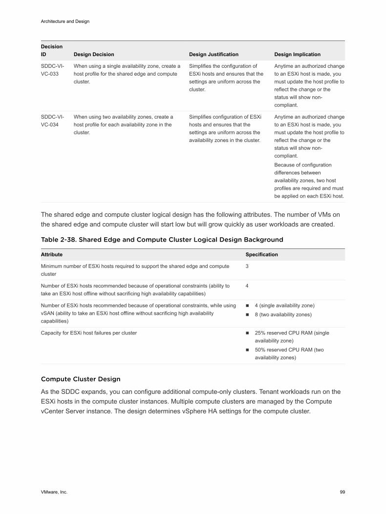
DecisionID Design Decision Design Justification Design Implication
SDDC-VI-VC-033
When using a single availability zone, create ahost profile for the shared edge and computecluster.
Simplifies the configuration ofESXi hosts and ensures that thesettings are uniform across thecluster.
Anytime an authorized changeto an ESXi host is made, youmust update the host profile toreflect the change or thestatus will show non-compliant.
SDDC-VI-VC-034
When using two availability zones, create ahost profile for each availability zone in thecluster.
Simplifies configuration of ESXihosts and ensures that thesettings are uniform across theavailability zones in the cluster.
Anytime an authorized changeto an ESXi host is made, youmust update the host profile toreflect the change or thestatus will show non-compliant.
Because of configurationdifferences betweenavailability zones, two hostprofiles are required and mustbe applied on each ESXi host.
The shared edge and compute cluster logical design has the following attributes. The number of VMs onthe shared edge and compute cluster will start low but will grow quickly as user workloads are created.
Table 2-38. Shared Edge and Compute Cluster Logical Design Background
Attribute Specification
Minimum number of ESXi hosts required to support the shared edge and computecluster
3
Number of ESXi hosts recommended because of operational constraints (ability totake an ESXi host offline without sacrificing high availability capabilities)
4
Number of ESXi hosts recommended because of operational constraints, while usingvSAN (ability to take an ESXi host offline without sacrificing high availabilitycapabilities)
n 4 (single availability zone)
n 8 (two availability zones)
Capacity for ESXi host failures per cluster n 25% reserved CPU RAM (singleavailability zone)
n 50% reserved CPU RAM (twoavailability zones)
Compute Cluster Design
As the SDDC expands, you can configure additional compute-only clusters. Tenant workloads run on theESXi hosts in the compute cluster instances. Multiple compute clusters are managed by the ComputevCenter Server instance. The design determines vSphere HA settings for the compute cluster.
Architecture and Design
VMware, Inc. 99
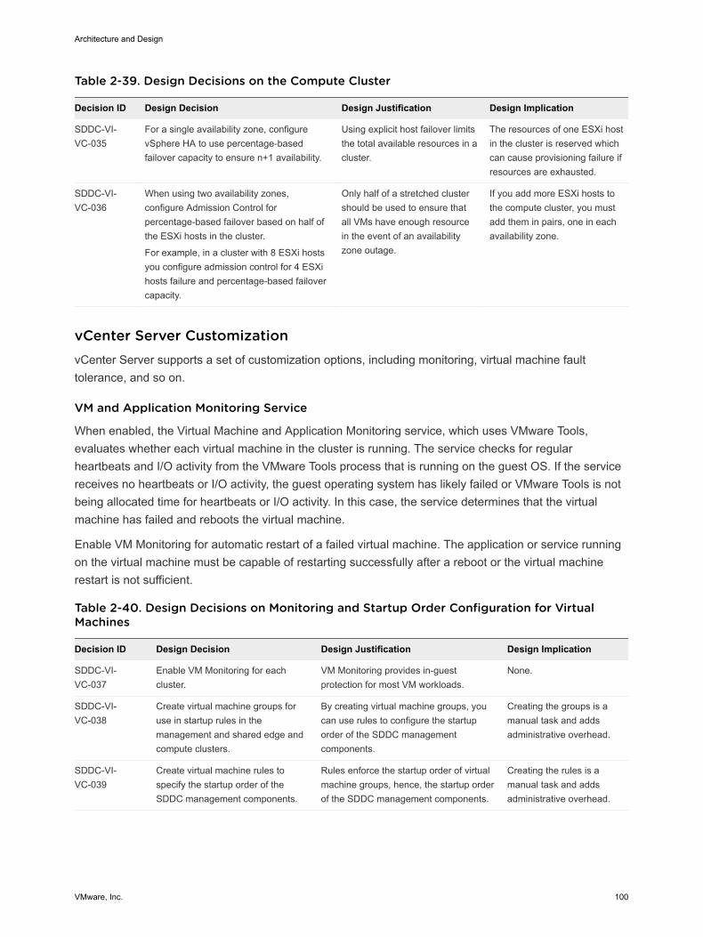
Table 2-39. Design Decisions on the Compute Cluster
Decision ID Design Decision Design Justification Design Implication
SDDC-VI-VC-035
For a single availability zone, configurevSphere HA to use percentage-basedfailover capacity to ensure n+1 availability.
Using explicit host failover limitsthe total available resources in acluster.
The resources of one ESXi hostin the cluster is reserved whichcan cause provisioning failure ifresources are exhausted.
SDDC-VI-VC-036
When using two availability zones,configure Admission Control forpercentage-based failover based on half ofthe ESXi hosts in the cluster.
For example, in a cluster with 8 ESXi hostsyou configure admission control for 4 ESXihosts failure and percentage-based failovercapacity.
Only half of a stretched clustershould be used to ensure thatall VMs have enough resourcein the event of an availabilityzone outage.
If you add more ESXi hosts tothe compute cluster, you mustadd them in pairs, one in eachavailability zone.
vCenter Server Customization vCenter Server supports a set of customization options, including monitoring, virtual machine faulttolerance, and so on.
VM and Application Monitoring Service
When enabled, the Virtual Machine and Application Monitoring service, which uses VMware Tools,evaluates whether each virtual machine in the cluster is running. The service checks for regularheartbeats and I/O activity from the VMware Tools process that is running on the guest OS. If the servicereceives no heartbeats or I/O activity, the guest operating system has likely failed or VMware Tools is notbeing allocated time for heartbeats or I/O activity. In this case, the service determines that the virtualmachine has failed and reboots the virtual machine.
Enable VM Monitoring for automatic restart of a failed virtual machine. The application or service runningon the virtual machine must be capable of restarting successfully after a reboot or the virtual machinerestart is not sufficient.
Table 2-40. Design Decisions on Monitoring and Startup Order Configuration for VirtualMachines
Decision ID Design Decision Design Justification Design Implication
SDDC-VI-VC-037
Enable VM Monitoring for eachcluster.
VM Monitoring provides in-guestprotection for most VM workloads.
None.
SDDC-VI-VC-038
Create virtual machine groups foruse in startup rules in themanagement and shared edge andcompute clusters.
By creating virtual machine groups, youcan use rules to configure the startuporder of the SDDC managementcomponents.
Creating the groups is amanual task and addsadministrative overhead.
SDDC-VI-VC-039
Create virtual machine rules tospecify the startup order of theSDDC management components.
Rules enforce the startup order of virtualmachine groups, hence, the startup orderof the SDDC management components.
Creating the rules is amanual task and addsadministrative overhead.
Architecture and Design
VMware, Inc. 100
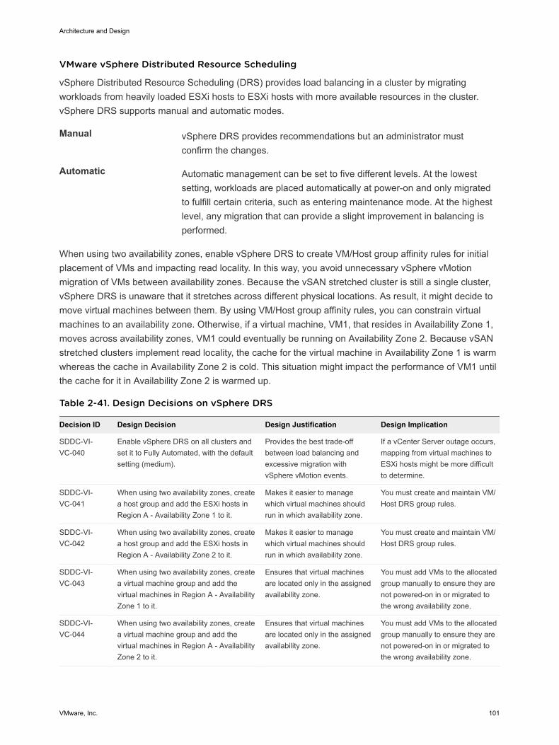
VMware vSphere Distributed Resource Scheduling
vSphere Distributed Resource Scheduling (DRS) provides load balancing in a cluster by migratingworkloads from heavily loaded ESXi hosts to ESXi hosts with more available resources in the cluster.vSphere DRS supports manual and automatic modes.
Manual vSphere DRS provides recommendations but an administrator mustconfirm the changes.
Automatic Automatic management can be set to five different levels. At the lowestsetting, workloads are placed automatically at power-on and only migratedto fulfill certain criteria, such as entering maintenance mode. At the highestlevel, any migration that can provide a slight improvement in balancing isperformed.
When using two availability zones, enable vSphere DRS to create VM/Host group affinity rules for initialplacement of VMs and impacting read locality. In this way, you avoid unnecessary vSphere vMotionmigration of VMs between availability zones. Because the vSAN stretched cluster is still a single cluster,vSphere DRS is unaware that it stretches across different physical locations. As result, it might decide tomove virtual machines between them. By using VM/Host group affinity rules, you can constrain virtualmachines to an availability zone. Otherwise, if a virtual machine, VM1, that resides in Availability Zone 1,moves across availability zones, VM1 could eventually be running on Availability Zone 2. Because vSANstretched clusters implement read locality, the cache for the virtual machine in Availability Zone 1 is warmwhereas the cache in Availability Zone 2 is cold. This situation might impact the performance of VM1 untilthe cache for it in Availability Zone 2 is warmed up.
Table 2-41. Design Decisions on vSphere DRS
Decision ID Design Decision Design Justification Design Implication
SDDC-VI-VC-040
Enable vSphere DRS on all clusters andset it to Fully Automated, with the defaultsetting (medium).
Provides the best trade-offbetween load balancing andexcessive migration withvSphere vMotion events.
If a vCenter Server outage occurs,mapping from virtual machines toESXi hosts might be more difficultto determine.
SDDC-VI-VC-041
When using two availability zones, createa host group and add the ESXi hosts inRegion A - Availability Zone 1 to it.
Makes it easier to managewhich virtual machines shouldrun in which availability zone.
You must create and maintain VM/Host DRS group rules.
SDDC-VI-VC-042
When using two availability zones, createa host group and add the ESXi hosts inRegion A - Availability Zone 2 to it.
Makes it easier to managewhich virtual machines shouldrun in which availability zone.
You must create and maintain VM/Host DRS group rules.
SDDC-VI-VC-043
When using two availability zones, createa virtual machine group and add thevirtual machines in Region A - AvailabilityZone 1 to it.
Ensures that virtual machinesare located only in the assignedavailability zone.
You must add VMs to the allocatedgroup manually to ensure they arenot powered-on in or migrated tothe wrong availability zone.
SDDC-VI-VC-044
When using two availability zones, createa virtual machine group and add thevirtual machines in Region A - AvailabilityZone 2 to it.
Ensures that virtual machinesare located only in the assignedavailability zone.
You must add VMs to the allocatedgroup manually to ensure they arenot powered-on in or migrated tothe wrong availability zone.
Architecture and Design
VMware, Inc. 101
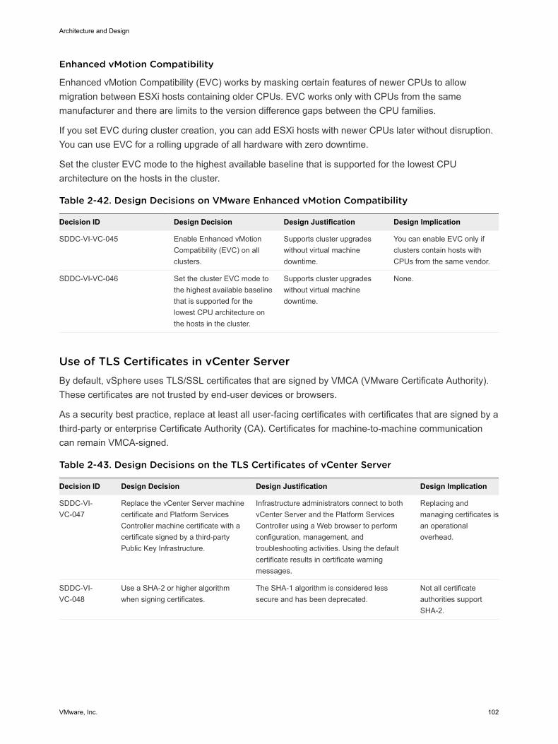
Enhanced vMotion Compatibility
Enhanced vMotion Compatibility (EVC) works by masking certain features of newer CPUs to allowmigration between ESXi hosts containing older CPUs. EVC works only with CPUs from the samemanufacturer and there are limits to the version difference gaps between the CPU families.
If you set EVC during cluster creation, you can add ESXi hosts with newer CPUs later without disruption.You can use EVC for a rolling upgrade of all hardware with zero downtime.
Set the cluster EVC mode to the highest available baseline that is supported for the lowest CPUarchitecture on the hosts in the cluster.
Table 2-42. Design Decisions on VMware Enhanced vMotion Compatibility
Decision ID Design Decision Design Justification Design Implication
SDDC-VI-VC-045 Enable Enhanced vMotionCompatibility (EVC) on allclusters.
Supports cluster upgradeswithout virtual machinedowntime.
You can enable EVC only ifclusters contain hosts withCPUs from the same vendor.
SDDC-VI-VC-046 Set the cluster EVC mode tothe highest available baselinethat is supported for thelowest CPU architecture onthe hosts in the cluster.
Supports cluster upgradeswithout virtual machinedowntime.
None.
Use of TLS Certificates in vCenter Server By default, vSphere uses TLS/SSL certificates that are signed by VMCA (VMware Certificate Authority).These certificates are not trusted by end-user devices or browsers.
As a security best practice, replace at least all user-facing certificates with certificates that are signed by athird-party or enterprise Certificate Authority (CA). Certificates for machine-to-machine communicationcan remain VMCA-signed.
Table 2-43. Design Decisions on the TLS Certificates of vCenter Server
Decision ID Design Decision Design Justification Design Implication
SDDC-VI-VC-047
Replace the vCenter Server machinecertificate and Platform ServicesController machine certificate with acertificate signed by a third-partyPublic Key Infrastructure.
Infrastructure administrators connect to bothvCenter Server and the Platform ServicesController using a Web browser to performconfiguration, management, andtroubleshooting activities. Using the defaultcertificate results in certificate warningmessages.
Replacing andmanaging certificates isan operationaloverhead.
SDDC-VI-VC-048
Use a SHA-2 or higher algorithmwhen signing certificates.
The SHA-1 algorithm is considered lesssecure and has been deprecated.
Not all certificateauthorities supportSHA-2.
Architecture and Design
VMware, Inc. 102
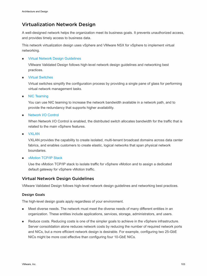
Virtualization Network Design A well-designed network helps the organization meet its business goals. It prevents unauthorized access,and provides timely access to business data.
This network virtualization design uses vSphere and VMware NSX for vSphere to implement virtualnetworking.
n Virtual Network Design Guidelines
VMware Validated Design follows high-level network design guidelines and networking bestpractices.
n Virtual Switches
Virtual switches simplify the configuration process by providing a single pane of glass for performingvirtual network management tasks.
n NIC Teaming
You can use NIC teaming to increase the network bandwidth available in a network path, and toprovide the redundancy that supports higher availability.
n Network I/O Control
When Network I/O Control is enabled, the distributed switch allocates bandwidth for the traffic that isrelated to the main vSphere features.
n VXLAN
VXLAN provides the capability to create isolated, multi-tenant broadcast domains across data centerfabrics, and enables customers to create elastic, logical networks that span physical networkboundaries.
n vMotion TCP/IP Stack
Use the vMotion TCP/IP stack to isolate traffic for vSphere vMotion and to assign a dedicateddefault gateway for vSphere vMotion traffic.
Virtual Network Design Guidelines VMware Validated Design follows high-level network design guidelines and networking best practices.
Design Goals
The high-level design goals apply regardless of your environment.
n Meet diverse needs. The network must meet the diverse needs of many different entities in anorganization. These entities include applications, services, storage, administrators, and users.
n Reduce costs. Reducing costs is one of the simpler goals to achieve in the vSphere infrastructure.Server consolidation alone reduces network costs by reducing the number of required network portsand NICs, but a more efficient network design is desirable. For example, configuring two 25-GbENICs might be more cost effective than configuring four 10-GbE NICs.
Architecture and Design
VMware, Inc. 103
n Improve performance. You can achieve performance improvement and decrease the time that isrequired to perform maintenance by providing sufficient bandwidth, which reduces contention andlatency.
n Improve availability. A well-designed network improves availability, usually by providing networkredundancy.
n Support security. A well-designed network supports an acceptable level of security through controlledaccess and isolation, where required.
n Enhance infrastructure functionality. You can configure the network to support vSphere features suchas vSphere vMotion, vSphere High Availability, and vSphere Fault Tolerance.
Best Practices
Follow networking best practices throughout your environment.
n Separate network services from one another to achieve greater security and better performance.
n Use Network I/O Control and traffic shaping to guarantee bandwidth to critical virtual machines.During network contention, these critical virtual machines will receive a higher percentage of thebandwidth.
n Separate network services on a single vSphere Distributed Switch by attaching them to port groupswith different VLAN IDs.
n Keep vSphere vMotion traffic on a separate network.
When a migration using vSphere vMotion occurs, the contents of the memory of the guest operatingsystem is transmitted over the network. You can place vSphere vMotion on a separate network byusing a dedicated vSphere vMotion VLAN.
n When using pass-through devices with Linux kernel version 2.6.20 or an earlier guest OS, avoid MSIand MSI-X modes. These modes have significant performance impact.
n For best performance, use VMXNET3 virtual machine NICs.
n Ensure that physical network adapters that are connected to the same vSphere Standard Switch orvSphere Distributed Switch, are also connected to the same physical network.
Network Segmentation and VLANs
Separating different types of traffic is required to reduce contention and latency, and for access security.
High latency on any network can negatively affect performance. Some components are more sensitive tohigh latency than others. For example, reducing latency is important on the IP storage and the vSphereFault Tolerance logging network because latency on these networks can negatively affect theperformance of multiple virtual machines.
According to the application or service, high latency on specific virtual machine networks can alsonegatively affect performance. Use information gathered from the current state analysis and frominterviews with key stakeholder and SMEs to determine which workloads and networks are especiallysensitive to high latency.
Architecture and Design
VMware, Inc. 104
Virtual Networks
Determine the number of networks or VLANs that are required depending on the type of traffic.
n vSphere operational traffic.
n Management
n vMotion
n vSAN
n NFS Storage
n vSphere Replication
n VXLAN
n Traffic that supports the services and applications in the organization.
Virtual Switches Virtual switches simplify the configuration process by providing a single pane of glass for performingvirtual network management tasks.
Virtual Switch Design Background
A distributed switch offers several enhancements over a standard switch such as centralized controlplane and support for traffic monitoring features.
Centralizedmanagement
Because distributed switches are created and managed centrally on avCenter Server system, switch configuration is more consistent acrossESXi hosts. Centralized management saves time, reduces mistakes, andreduces operational costs.
Additional features Distributed switches have features that are not available on standard virtualswitches.
NetFlow and port mirroring provide monitoring and troubleshootingcapabilities to the virtual infrastructure.
To guarantee that traffic types with high priority have enough networkcapacity, you can assign shares to these traffic types by using Network I/OControl.
To ensure that every network adapter is used when the network traffic ishigh, you can use the Route Based on Physical NIC Load teaming policy.The distributed switch directs the traffic from one physical network adapterto another if the usage of an adapter remains at or above 75% for 30seconds.
Disadvantages If vCenter Server is unavailable, distributed switches are not manageable.Consider vCenter Server a Tier 1 application.
Architecture and Design
VMware, Inc. 105
Virtual Switch Number and Configuration
Create a single virtual switch per cluster. For each type of network traffic, configure a port group tosimplify configuration and monitoring.
Table 2-44. Design Decisions on Virtual Switch Type and Configuration
Decision ID Design Decision Design Justification Design Implication
SDDC-VI-NET-001
Use vSphere DistributedSwitches (VDSs).
vSphere Distributed Switches simplifymanagement.
Migration from a standard switchto a distributed switch requires aminimum of two physical NICs tomaintain redundancy.
SDDC-VI-NET-002
Use a single vSphereDistributed Switch percluster.
Reduces complexity of the network design.
Reduces the size of the fault domain.
Increases the number of vSphereDistributed Switches that must bemanaged.
SDDC-VI-NET-003
Use ephemeral port bindingfor the management portgroup.
Using ephemeral port binding provides theoption for recovery of the vCenter Serverinstance that is managing the distributedswitch.
Port-level permissions andcontrols are lost across powercycles, and no historical context issaved.
SDDC-VI-NET-004
Use static port binding for allnon-management portgroups.
Static binding ensures a virtual machineconnects to the same port on the vSphereDistributed Switch. This allows forhistorical data and port level monitoring .
None.
Health Check
The health check service helps identify and troubleshoot configuration errors in vSphere distributedswitches.
Health check helps identify the following common configuration errors.
n Mismatching VLAN trunks between an ESXi host and the physical switches it's connected to.
n Mismatching MTU settings between physical network adapters, distributed switches, and physicalswitch ports.
n Mismatching virtual switch teaming policies for the physical switch port-channel settings.
Health check monitors VLAN, MTU, and teaming policies.
VLANs Checks whether the VLAN settings on the distributed switch match thetrunk port configuration on the connected physical switch ports.
MTU For each VLAN, determines whether the MTU size configuration for jumboframes on the physical access switch port matches the distributed switchMTU setting.
Teaming policies Determines whether the connected access ports of the physical switch thatparticipate in an EtherChannel are paired with distributed ports whoseteaming policy is Route based on IP hash.
Health check is limited to the access switch port to which the NICs of the ESXi hosts are connected.
Architecture and Design
VMware, Inc. 106
Table 2-45. Design Decisions on Distributed Switch Health Check
Design ID Design Decision Design Justification Design Implication
SDDC-VI-NET-005 Enable vSphere DistributedSwitch Health Check on alldistributed switches.
vSphere Distributed SwitchHealth Check verifies that allVLANS are trunked to allESXi hosts attached to thevSphere Distributed Switchand MTU sizes match thephysical network.
You must have a minimum oftwo physical uplinks to use thisfeature.
In a multiple availability zoneconfiguration, some VLANs arenot available to all ESXi hostsin the cluster which triggersalarms.
Note For VLAN and MTU checks, at least two physical NICs for the distributed switch are required. Fora teaming policy check, at least two physical NICs and two hosts are required when applying the policy.
Management Cluster Distributed Switch
The cluster uses a single vSphere distributed switch whose design includes traffic types on the switch, thenumber of required NICs, jumbo frames configuration, port groups settings, and Network I/O Controlsettings.
Table 2-46. Virtual Switch for the Management Cluster
vSphere DistributedSwitch Name Function
Network I/OControl
Number ofPhysical NIC Ports MTU
sfo01-m01-vds01 n ESXi Management
n Network IP Storage (NFS)
n vSAN
n vSphere vMotion
n VXLAN Tunnel Endpoint (VTEP)
n vSphere Replication/vSphere Replication NFC
n Uplinks (2) for ECMP
Enabled 2 9000
Table 2-47. Configuration Settings of the Management Port Group
Parameter Setting
Failover detection Link status only
Notify switches Enabled
Failback Yes
Failover order Active uplinks: Uplink1, Uplink2
Architecture and Design
VMware, Inc. 107
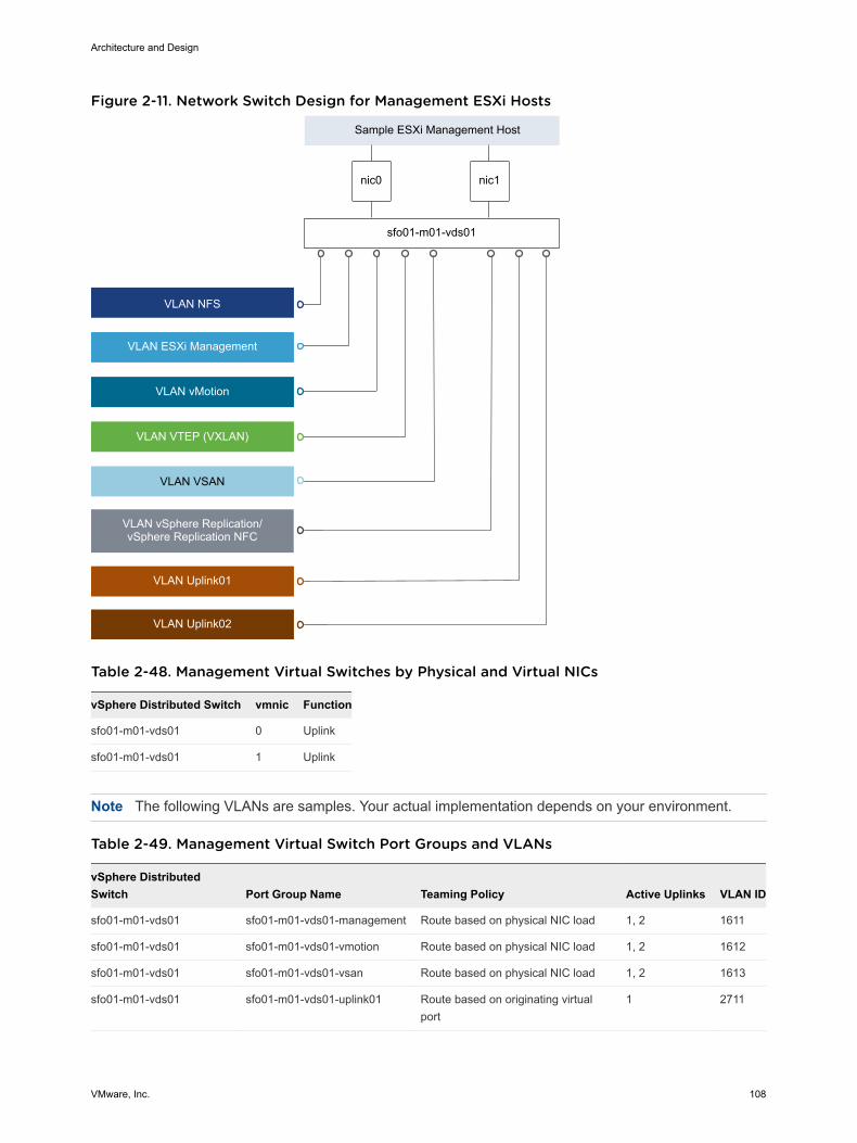
Figure 2-11. Network Switch Design for Management ESXi Hosts
nic0 nic1
VLAN VSAN
VLAN ESXi Management
VLAN vMotion
VLAN VTEP (VXLAN)
Sample ESXi Management Host
VLAN vSphere Replication/vSphere Replication NFC
sfo01-m01-vds01
VLAN NFS
VLAN Uplink01
VLAN Uplink02
Table 2-48. Management Virtual Switches by Physical and Virtual NICs
vSphere Distributed Switch vmnic Function
sfo01-m01-vds01 0 Uplink
sfo01-m01-vds01 1 Uplink
Note The following VLANs are samples. Your actual implementation depends on your environment.
Table 2-49. Management Virtual Switch Port Groups and VLANs
vSphere DistributedSwitch Port Group Name Teaming Policy Active Uplinks VLAN ID
sfo01-m01-vds01 sfo01-m01-vds01-management Route based on physical NIC load 1, 2 1611
sfo01-m01-vds01 sfo01-m01-vds01-vmotion Route based on physical NIC load 1, 2 1612
sfo01-m01-vds01 sfo01-m01-vds01-vsan Route based on physical NIC load 1, 2 1613
sfo01-m01-vds01 sfo01-m01-vds01-uplink01 Route based on originating virtualport
1 2711
Architecture and Design
VMware, Inc. 108
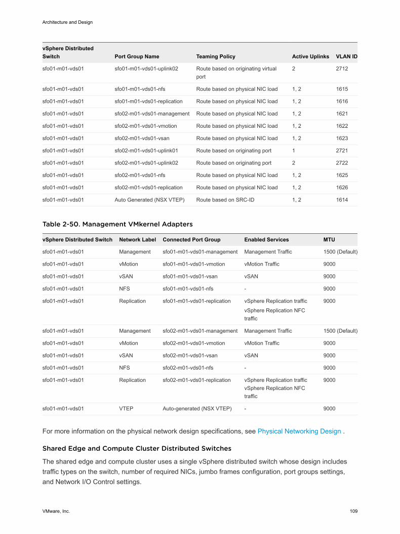
vSphere DistributedSwitch Port Group Name Teaming Policy Active Uplinks VLAN ID
sfo01-m01-vds01 sfo01-m01-vds01-uplink02 Route based on originating virtualport
2 2712
sfo01-m01-vds01 sfo01-m01-vds01-nfs Route based on physical NIC load 1, 2 1615
sfo01-m01-vds01 sfo01-m01-vds01-replication Route based on physical NIC load 1, 2 1616
sfo01-m01-vds01 sfo02-m01-vds01-management Route based on physical NIC load 1, 2 1621
sfo01-m01-vds01 sfo02-m01-vds01-vmotion Route based on physical NIC load 1, 2 1622
sfo01-m01-vds01 sfo02-m01-vds01-vsan Route based on physical NIC load 1, 2 1623
sfo01-m01-vds01 sfo02-m01-vds01-uplink01 Route based on originating port 1 2721
sfo01-m01-vds01 sfo02-m01-vds01-uplink02 Route based on originating port 2 2722
sfo01-m01-vds01 sfo02-m01-vds01-nfs Route based on physical NIC load 1, 2 1625
sfo01-m01-vds01 sfo02-m01-vds01-replication Route based on physical NIC load 1, 2 1626
sfo01-m01-vds01 Auto Generated (NSX VTEP) Route based on SRC-ID 1, 2 1614
Table 2-50. Management VMkernel Adapters
vSphere Distributed Switch Network Label Connected Port Group Enabled Services MTU
sfo01-m01-vds01 Management sfo01-m01-vds01-management Management Traffic 1500 (Default)
sfo01-m01-vds01 vMotion sfo01-m01-vds01-vmotion vMotion Traffic 9000
sfo01-m01-vds01 vSAN sfo01-m01-vds01-vsan vSAN 9000
sfo01-m01-vds01 NFS sfo01-m01-vds01-nfs - 9000
sfo01-m01-vds01 Replication sfo01-m01-vds01-replication vSphere Replication traffic
vSphere Replication NFCtraffic
9000
sfo01-m01-vds01 Management sfo02-m01-vds01-management Management Traffic 1500 (Default)
sfo01-m01-vds01 vMotion sfo02-m01-vds01-vmotion vMotion Traffic 9000
sfo01-m01-vds01 vSAN sfo02-m01-vds01-vsan vSAN 9000
sfo01-m01-vds01 NFS sfo02-m01-vds01-nfs - 9000
sfo01-m01-vds01 Replication sfo02-m01-vds01-replication vSphere Replication trafficvSphere Replication NFCtraffic
9000
sfo01-m01-vds01 VTEP Auto-generated (NSX VTEP) - 9000
For more information on the physical network design specifications, see Physical Networking Design .
Shared Edge and Compute Cluster Distributed Switches
The shared edge and compute cluster uses a single vSphere distributed switch whose design includestraffic types on the switch, number of required NICs, jumbo frames configuration, port groups settings,and Network I/O Control settings.
Architecture and Design
VMware, Inc. 109
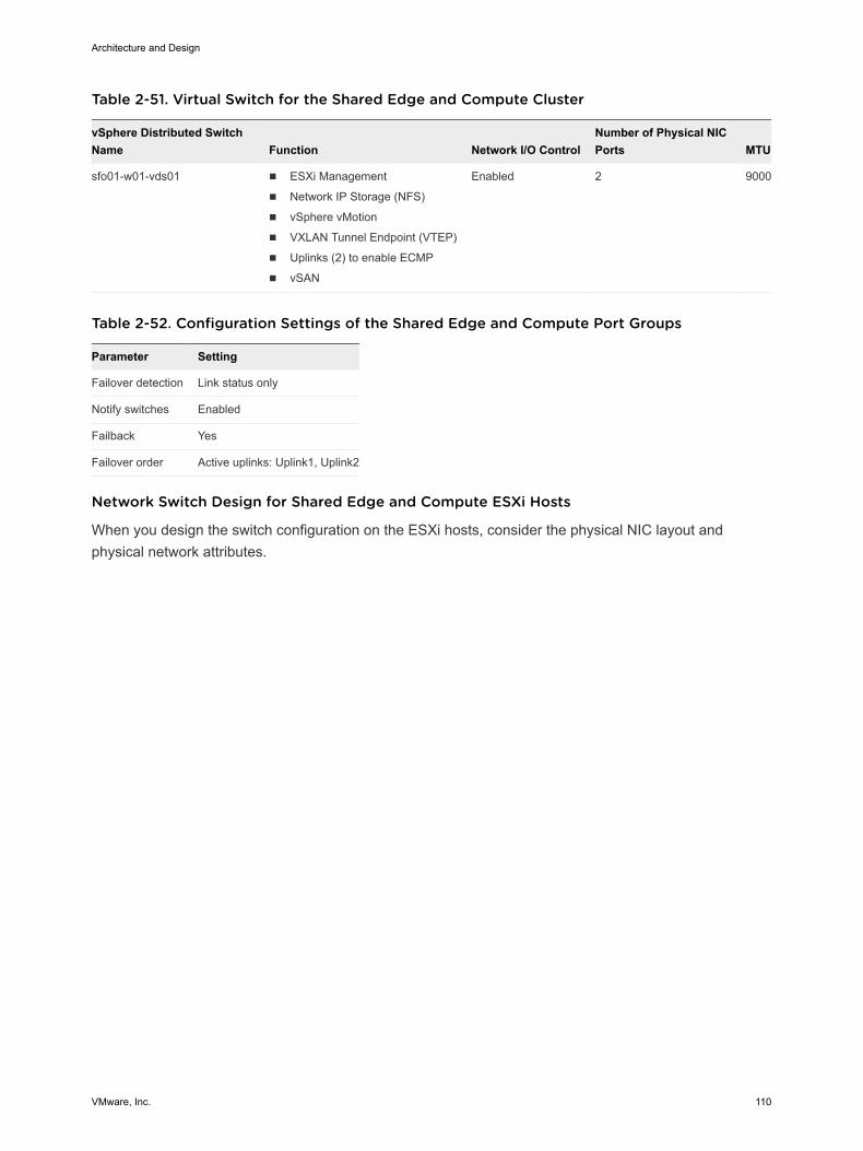
Table 2-51. Virtual Switch for the Shared Edge and Compute Cluster
vSphere Distributed SwitchName Function Network I/O Control
Number of Physical NICPorts MTU
sfo01-w01-vds01 n ESXi Management
n Network IP Storage (NFS)
n vSphere vMotion
n VXLAN Tunnel Endpoint (VTEP)
n Uplinks (2) to enable ECMP
n vSAN
Enabled 2 9000
Table 2-52. Configuration Settings of the Shared Edge and Compute Port Groups
Parameter Setting
Failover detection Link status only
Notify switches Enabled
Failback Yes
Failover order Active uplinks: Uplink1, Uplink2
Network Switch Design for Shared Edge and Compute ESXi Hosts
When you design the switch configuration on the ESXi hosts, consider the physical NIC layout andphysical network attributes.
Architecture and Design
VMware, Inc. 110
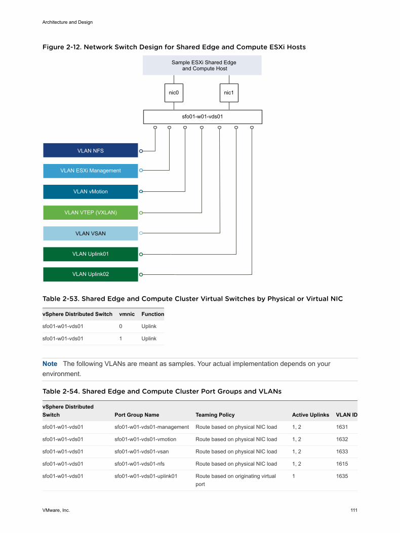
Figure 2-12. Network Switch Design for Shared Edge and Compute ESXi Hosts
nic0 nic1
VLAN VSAN
VLAN ESXi Management
VLAN vMotion
VLAN VTEP (VXLAN)
Sample ESXi Shared Edge and Compute Host
sfo01-w01-vds01
VLAN NFS
VLAN Uplink01
VLAN Uplink02
Table 2-53. Shared Edge and Compute Cluster Virtual Switches by Physical or Virtual NIC
vSphere Distributed Switch vmnic Function
sfo01-w01-vds01 0 Uplink
sfo01-w01-vds01 1 Uplink
Note The following VLANs are meant as samples. Your actual implementation depends on yourenvironment.
Table 2-54. Shared Edge and Compute Cluster Port Groups and VLANs
vSphere DistributedSwitch Port Group Name Teaming Policy Active Uplinks VLAN ID
sfo01-w01-vds01 sfo01-w01-vds01-management Route based on physical NIC load 1, 2 1631
sfo01-w01-vds01 sfo01-w01-vds01-vmotion Route based on physical NIC load 1, 2 1632
sfo01-w01-vds01 sfo01-w01-vds01-vsan Route based on physical NIC load 1, 2 1633
sfo01-w01-vds01 sfo01-w01-vds01-nfs Route based on physical NIC load 1, 2 1615
sfo01-w01-vds01 sfo01-w01-vds01-uplink01 Route based on originating virtualport
1 1635
Architecture and Design
VMware, Inc. 111
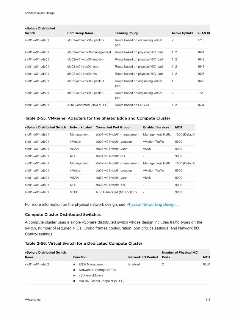
vSphere DistributedSwitch Port Group Name Teaming Policy Active Uplinks VLAN ID
sfo01-w01-vds01 sfo01-w01-vds01-uplink02 Route based on originating virtualport
2 2713
sfo01-w01-vds01 sfo02-w01-vds01-management Route based on physical NIC load 1, 2 1641
sfo01-w01-vds01 sfo02-w01-vds01-vmotion Route based on physical NIC load 1, 2 1642
sfo01-w01-vds01 sfo02-w01-vds01-vsan Route based on physical NIC load 1, 2 1643
sfo01-w01-vds01 sfo02-w01-vds01-nfs Route based on physical NIC load 1, 2 1625
sfo01-w01-vds01 sfo02-w01-vds01-uplink01 Route based on originating virtualport
1 1645
sfo01-w01-vds01 sfo02-w01-vds01-uplink02 Route based on originating virtualport
2 2723
sfo01-w01-vds01 Auto Generated (NSX VTEP) Route based on SRC-ID 1, 2 1634
Table 2-55. VMkernel Adapters for the Shared Edge and Compute Cluster
vSphere Distributed Switch Network Label Connected Port Group Enabled Services MTU
sfo01-w01-vds01 Management sfo01-w01-vds01-management Management Traffic 1500 (Default)
sfo01-w01-vds01 vMotion sfo01-w01-vds01-vmotion vMotion Traffic 9000
sfo01-w01-vds01 VSAN sfo01-w01-vds01-vsan vSAN 9000
sfo01-w01-vds01 NFS sfo01-w01-vds01-nfs - 9000
sfo01-w01-vds01 Management sfo02-w01-vds01-management Management Traffic 1500 (Default)
sfo01-w01-vds01 vMotion sfo02-w01-vds01-vmotion vMotion Traffic 9000
sfo01-w01-vds01 VSAN sfo02-w01-vds01-vsan vSAN 9000
sfo01-w01-vds01 NFS sfo02-w01-vds01-nfs - 9000
sfo01-w01-vds01 VTEP Auto Generated (NSX VTEP) - 9000
For more information on the physical network design, see Physical Networking Design .
Compute Cluster Distributed Switches
А compute cluster uses a single vSphere distributed switch whose design includes traffic types on theswitch, number of required NICs, jumbo frames configuration, port groups settings, and Network I/OControl settings.
Table 2-56. Virtual Switch for a Dedicated Compute Cluster
vSphere Distributed SwitchName Function Network I/O Control
Number of Physical NICPorts MTU
sfo01-w01-vds02 n ESXi Management
n Network IP Storage (NFS)
n vSphere vMotion
n VXLAN Tunnel Endpoint (VTEP)
Enabled 2 9000
Architecture and Design
VMware, Inc. 112
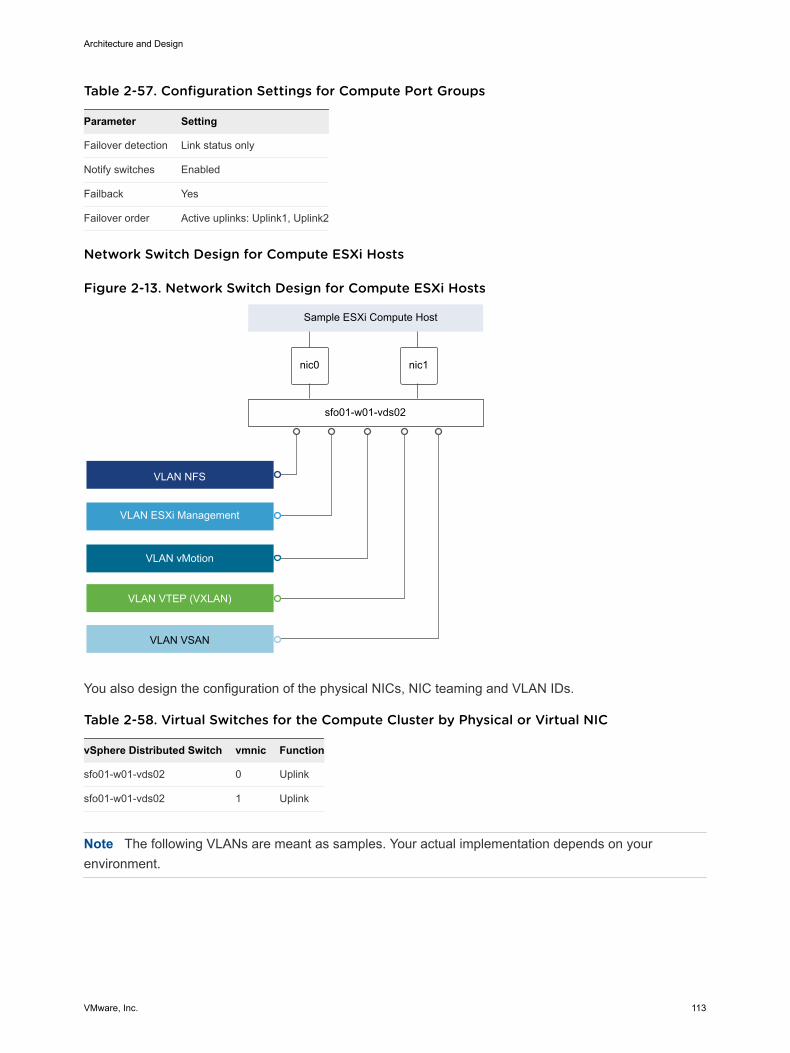
Table 2-57. Configuration Settings for Compute Port Groups
Parameter Setting
Failover detection Link status only
Notify switches Enabled
Failback Yes
Failover order Active uplinks: Uplink1, Uplink2
Network Switch Design for Compute ESXi Hosts
Figure 2-13. Network Switch Design for Compute ESXi Hosts
nic0 nic1
VLAN VSAN
VLAN ESXi Management
VLAN vMotion
VLAN VTEP (VXLAN)
Sample ESXi Compute Host
VLAN NFS
sfo01-w01-vds02
You also design the configuration of the physical NICs, NIC teaming and VLAN IDs.
Table 2-58. Virtual Switches for the Compute Cluster by Physical or Virtual NIC
vSphere Distributed Switch vmnic Function
sfo01-w01-vds02 0 Uplink
sfo01-w01-vds02 1 Uplink
Note The following VLANs are meant as samples. Your actual implementation depends on yourenvironment.
Architecture and Design
VMware, Inc. 113
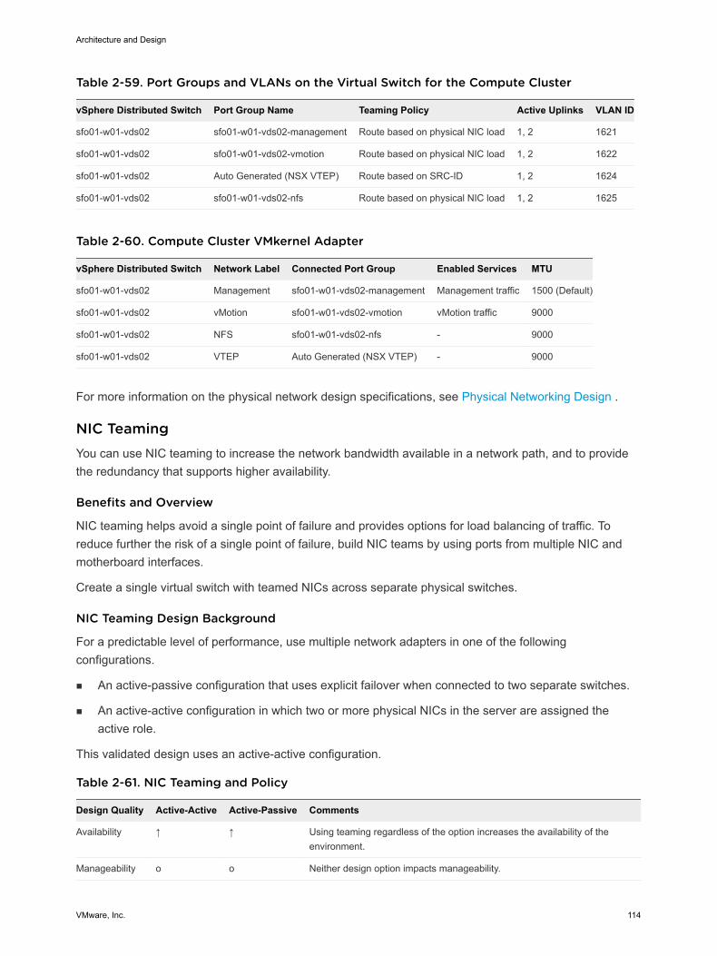
Table 2-59. Port Groups and VLANs on the Virtual Switch for the Compute Cluster
vSphere Distributed Switch Port Group Name Teaming Policy Active Uplinks VLAN ID
sfo01-w01-vds02 sfo01-w01-vds02-management Route based on physical NIC load 1, 2 1621
sfo01-w01-vds02 sfo01-w01-vds02-vmotion Route based on physical NIC load 1, 2 1622
sfo01-w01-vds02 Auto Generated (NSX VTEP) Route based on SRC-ID 1, 2 1624
sfo01-w01-vds02 sfo01-w01-vds02-nfs Route based on physical NIC load 1, 2 1625
Table 2-60. Compute Cluster VMkernel Adapter
vSphere Distributed Switch Network Label Connected Port Group Enabled Services MTU
sfo01-w01-vds02 Management sfo01-w01-vds02-management Management traffic 1500 (Default)
sfo01-w01-vds02 vMotion sfo01-w01-vds02-vmotion vMotion traffic 9000
sfo01-w01-vds02 NFS sfo01-w01-vds02-nfs - 9000
sfo01-w01-vds02 VTEP Auto Generated (NSX VTEP) - 9000
For more information on the physical network design specifications, see Physical Networking Design .
NIC Teaming You can use NIC teaming to increase the network bandwidth available in a network path, and to providethe redundancy that supports higher availability.
Benefits and Overview
NIC teaming helps avoid a single point of failure and provides options for load balancing of traffic. Toreduce further the risk of a single point of failure, build NIC teams by using ports from multiple NIC andmotherboard interfaces.
Create a single virtual switch with teamed NICs across separate physical switches.
NIC Teaming Design Background
For a predictable level of performance, use multiple network adapters in one of the followingconfigurations.
n An active-passive configuration that uses explicit failover when connected to two separate switches.
n An active-active configuration in which two or more physical NICs in the server are assigned theactive role.
This validated design uses an active-active configuration.
Table 2-61. NIC Teaming and Policy
Design Quality Active-Active Active-Passive Comments
Availability ↑ ↑ Using teaming regardless of the option increases the availability of theenvironment.
Manageability o o Neither design option impacts manageability.
Architecture and Design
VMware, Inc. 114
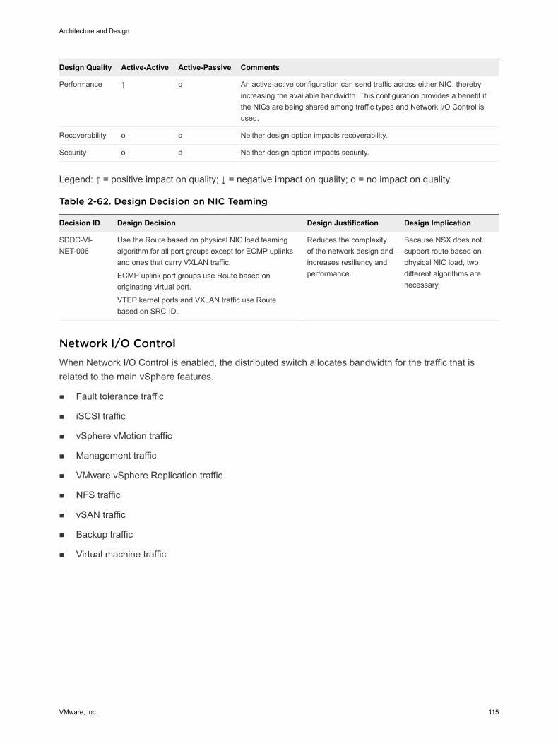
Design Quality Active-Active Active-Passive Comments
Performance ↑ o An active-active configuration can send traffic across either NIC, therebyincreasing the available bandwidth. This configuration provides a benefit ifthe NICs are being shared among traffic types and Network I/O Control isused.
Recoverability o o Neither design option impacts recoverability.
Security o o Neither design option impacts security.
Legend: ↑ = positive impact on quality; ↓ = negative impact on quality; o = no impact on quality.
Table 2-62. Design Decision on NIC Teaming
Decision ID Design Decision Design Justification Design Implication
SDDC-VI-NET-006
Use the Route based on physical NIC load teamingalgorithm for all port groups except for ECMP uplinksand ones that carry VXLAN traffic.
ECMP uplink port groups use Route based onoriginating virtual port.
VTEP kernel ports and VXLAN traffic use Routebased on SRC-ID.
Reduces the complexityof the network design andincreases resiliency andperformance.
Because NSX does notsupport route based onphysical NIC load, twodifferent algorithms arenecessary.
Network I/O Control When Network I/O Control is enabled, the distributed switch allocates bandwidth for the traffic that isrelated to the main vSphere features.
n Fault tolerance traffic
n iSCSI traffic
n vSphere vMotion traffic
n Management traffic
n VMware vSphere Replication traffic
n NFS traffic
n vSAN traffic
n Backup traffic
n Virtual machine traffic
Architecture and Design
VMware, Inc. 115
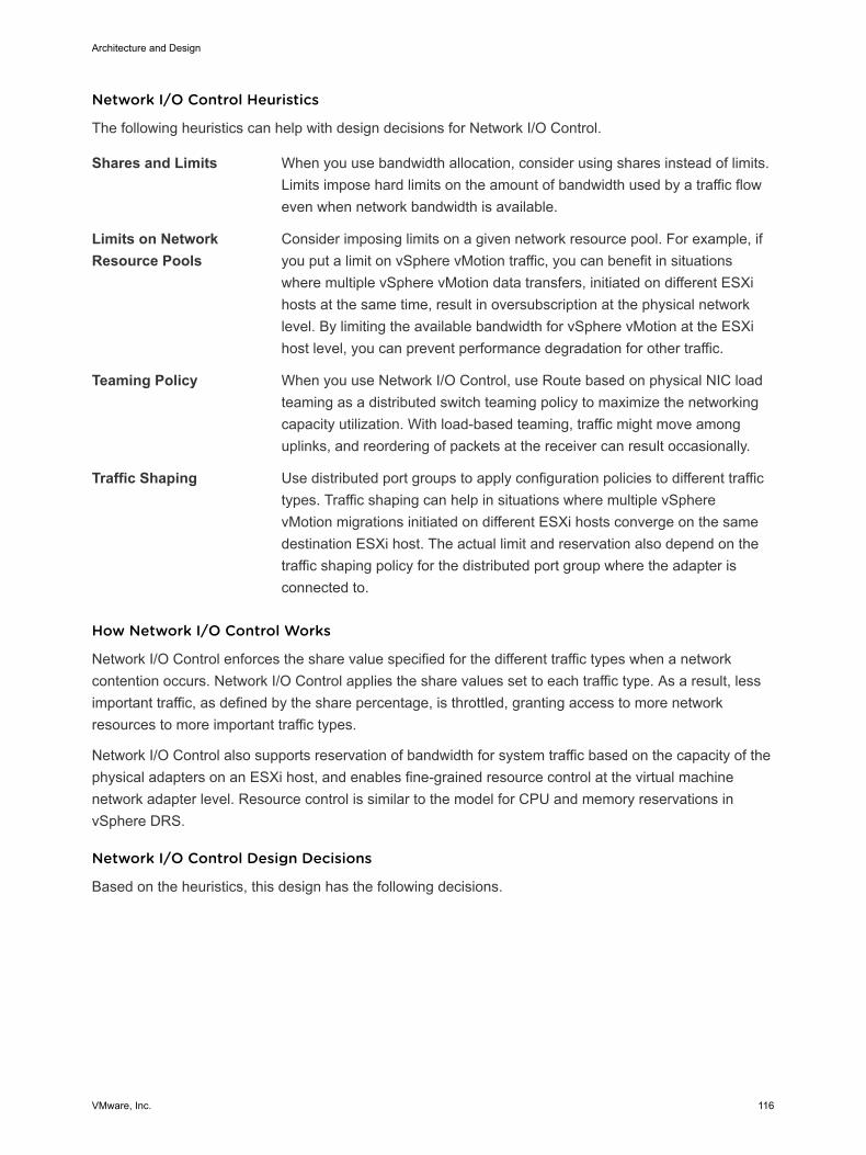
Network I/O Control Heuristics
The following heuristics can help with design decisions for Network I/O Control.
Shares and Limits When you use bandwidth allocation, consider using shares instead of limits.Limits impose hard limits on the amount of bandwidth used by a traffic floweven when network bandwidth is available.
Limits on NetworkResource Pools
Consider imposing limits on a given network resource pool. For example, ifyou put a limit on vSphere vMotion traffic, you can benefit in situationswhere multiple vSphere vMotion data transfers, initiated on different ESXihosts at the same time, result in oversubscription at the physical networklevel. By limiting the available bandwidth for vSphere vMotion at the ESXihost level, you can prevent performance degradation for other traffic.
Teaming Policy When you use Network I/O Control, use Route based on physical NIC loadteaming as a distributed switch teaming policy to maximize the networkingcapacity utilization. With load-based teaming, traffic might move amonguplinks, and reordering of packets at the receiver can result occasionally.
Traffic Shaping Use distributed port groups to apply configuration policies to different traffictypes. Traffic shaping can help in situations where multiple vSpherevMotion migrations initiated on different ESXi hosts converge on the samedestination ESXi host. The actual limit and reservation also depend on thetraffic shaping policy for the distributed port group where the adapter isconnected to.
How Network I/O Control Works
Network I/O Control enforces the share value specified for the different traffic types when a networkcontention occurs. Network I/O Control applies the share values set to each traffic type. As a result, lessimportant traffic, as defined by the share percentage, is throttled, granting access to more networkresources to more important traffic types.
Network I/O Control also supports reservation of bandwidth for system traffic based on the capacity of thephysical adapters on an ESXi host, and enables fine-grained resource control at the virtual machinenetwork adapter level. Resource control is similar to the model for CPU and memory reservations invSphere DRS.
Network I/O Control Design Decisions
Based on the heuristics, this design has the following decisions.
Architecture and Design
VMware, Inc. 116
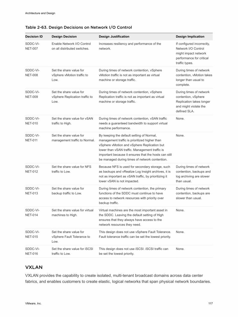
Table 2-63. Design Decisions on Network I/O Control
Decision ID Design Decision Design Justification Design Implication
SDDC-VI-NET-007
Enable Network I/O Controlon all distributed switches.
Increases resiliency and performance of thenetwork.
If configured incorrectly,Network I/O Controlmight impact networkperformance for criticaltraffic types.
SDDC-VI-NET-008
Set the share value forvSphere vMotion traffic toLow.
During times of network contention, vSpherevMotion traffic is not as important as virtualmachine or storage traffic.
During times of networkcontention, vMotion takeslonger than usual tocomplete.
SDDC-VI-NET-009
Set the share value forvSphere Replication traffic toLow.
During times of network contention, vSphereReplication traffic is not as important as virtualmachine or storage traffic.
During times of networkcontention, vSphereReplication takes longerand might violate thedefined SLA.
SDDC-VI-NET-010
Set the share value for vSANtraffic to High.
During times of network contention, vSAN trafficneeds a guaranteed bandwidth to support virtualmachine performance.
None.
SDDC-VI-NET-011
Set the share value formanagement traffic to Normal.
By keeping the default setting of Normal,management traffic is prioritized higher thanvSphere vMotion and vSphere Replication butlower than vSAN traffic. Management traffic isimportant because it ensures that the hosts can stillbe managed during times of network contention.
None.
SDDC-VI-NET-012
Set the share value for NFStraffic to Low.
Because NFS is used for secondary storage, suchas backups and vRealize Log Insight archives, it isnot as important as vSAN traffic, by prioritizing itlower vSAN is not impacted.
During times of networkcontention, backups andlog archiving are slowerthan usual.
SDDC-VI-NET-013
Set the share value forbackup traffic to Low.
During times of network contention, the primaryfunctions of the SDDC must continue to haveaccess to network resources with priority overbackup traffic.
During times of networkcontention, backups areslower than usual.
SDDC-VI-NET-014
Set the share value for virtualmachines to High.
Virtual machines are the most important asset inthe SDDC. Leaving the default setting of Highensures that they always have access to thenetwork resources they need.
None.
SDDC-VI-NET-015
Set the share value forvSphere Fault Tolerance toLow.
This design does not use vSphere Fault Tolerance.Fault tolerance traffic can be set the lowest priority.
None.
SDDC-VI-NET-016
Set the share value for iSCSItraffic to Low.
This design does not use iSCSI. iSCSI traffic canbe set the lowest priority.
None.
VXLAN VXLAN provides the capability to create isolated, multi-tenant broadcast domains across data centerfabrics, and enables customers to create elastic, logical networks that span physical network boundaries.
Architecture and Design
VMware, Inc. 117
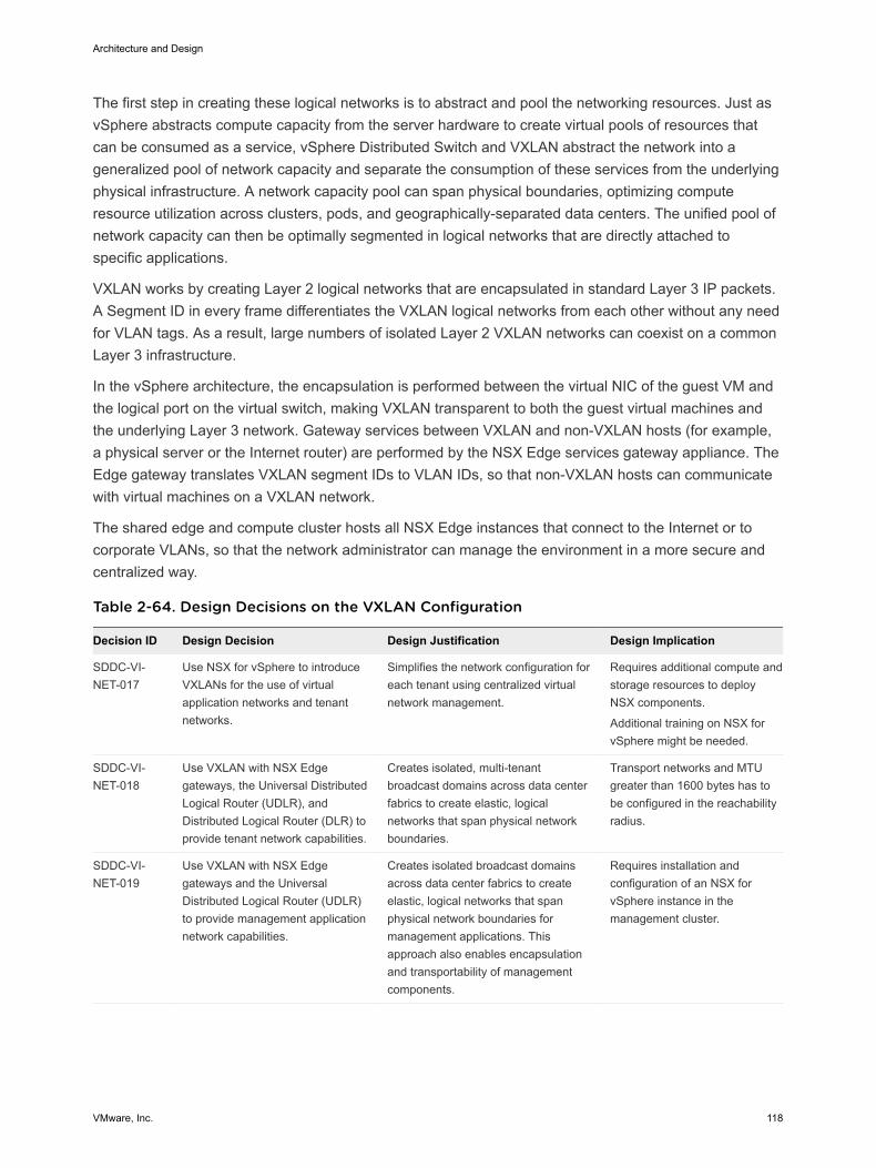
The first step in creating these logical networks is to abstract and pool the networking resources. Just asvSphere abstracts compute capacity from the server hardware to create virtual pools of resources thatcan be consumed as a service, vSphere Distributed Switch and VXLAN abstract the network into ageneralized pool of network capacity and separate the consumption of these services from the underlyingphysical infrastructure. A network capacity pool can span physical boundaries, optimizing computeresource utilization across clusters, pods, and geographically-separated data centers. The unified pool ofnetwork capacity can then be optimally segmented in logical networks that are directly attached tospecific applications.
VXLAN works by creating Layer 2 logical networks that are encapsulated in standard Layer 3 IP packets.A Segment ID in every frame differentiates the VXLAN logical networks from each other without any needfor VLAN tags. As a result, large numbers of isolated Layer 2 VXLAN networks can coexist on a commonLayer 3 infrastructure.
In the vSphere architecture, the encapsulation is performed between the virtual NIC of the guest VM andthe logical port on the virtual switch, making VXLAN transparent to both the guest virtual machines andthe underlying Layer 3 network. Gateway services between VXLAN and non-VXLAN hosts (for example,a physical server or the Internet router) are performed by the NSX Edge services gateway appliance. TheEdge gateway translates VXLAN segment IDs to VLAN IDs, so that non-VXLAN hosts can communicatewith virtual machines on a VXLAN network.
The shared edge and compute cluster hosts all NSX Edge instances that connect to the Internet or tocorporate VLANs, so that the network administrator can manage the environment in a more secure andcentralized way.
Table 2-64. Design Decisions on the VXLAN Configuration
Decision ID Design Decision Design Justification Design Implication
SDDC-VI-NET-017
Use NSX for vSphere to introduceVXLANs for the use of virtualapplication networks and tenantnetworks.
Simplifies the network configuration foreach tenant using centralized virtualnetwork management.
Requires additional compute andstorage resources to deployNSX components.
Additional training on NSX forvSphere might be needed.
SDDC-VI-NET-018
Use VXLAN with NSX Edgegateways, the Universal DistributedLogical Router (UDLR), andDistributed Logical Router (DLR) toprovide tenant network capabilities.
Creates isolated, multi-tenantbroadcast domains across data centerfabrics to create elastic, logicalnetworks that span physical networkboundaries.
Transport networks and MTUgreater than 1600 bytes has tobe configured in the reachabilityradius.
SDDC-VI-NET-019
Use VXLAN with NSX Edgegateways and the UniversalDistributed Logical Router (UDLR)to provide management applicationnetwork capabilities.
Creates isolated broadcast domainsacross data center fabrics to createelastic, logical networks that spanphysical network boundaries formanagement applications. Thisapproach also enables encapsulationand transportability of managementcomponents.
Requires installation andconfiguration of an NSX forvSphere instance in themanagement cluster.
Architecture and Design
VMware, Inc. 118
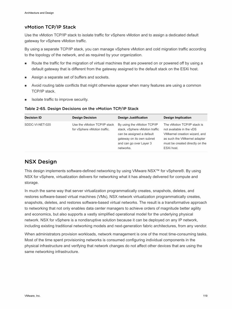
vMotion TCP/IP Stack Use the vMotion TCP/IP stack to isolate traffic for vSphere vMotion and to assign a dedicated defaultgateway for vSphere vMotion traffic.
By using a separate TCP/IP stack, you can manage vSphere vMotion and cold migration traffic accordingto the topology of the network, and as required by your organization.
n Route the traffic for the migration of virtual machines that are powered on or powered off by using adefault gateway that is different from the gateway assigned to the default stack on the ESXi host.
n Assign a separate set of buffers and sockets.
n Avoid routing table conflicts that might otherwise appear when many features are using a commonTCP/IP stack.
n Isolate traffic to improve security.
Table 2-65. Design Decisions on the vMotion TCP/IP Stack
Decision ID Design Decision Design Justification Design Implication
SDDC-VI-NET-020 Use the vMotion TCP/IP stackfor vSphere vMotion traffic.
By using the vMotion TCP/IPstack, vSphere vMotion trafficcan be assigned a defaultgateway on its own subnetand can go over Layer 3networks.
The vMotion TCP/IP stack isnot available in the vDSVMkernel creation wizard, andas such the VMkernel adaptermust be created directly on theESXi host.
NSX Design This design implements software-defined networking by using VMware NSX™ for vSphere®. By usingNSX for vSphere, virtualization delivers for networking what it has already delivered for compute andstorage.
In much the same way that server virtualization programmatically creates, snapshots, deletes, andrestores software-based virtual machines (VMs), NSX network virtualization programmatically creates,snapshots, deletes, and restores software-based virtual networks. The result is a transformative approachto networking that not only enables data center managers to achieve orders of magnitude better agilityand economics, but also supports a vastly simplified operational model for the underlying physicalnetwork. NSX for vSphere is a nondisruptive solution because it can be deployed on any IP network,including existing traditional networking models and next-generation fabric architectures, from any vendor.
When administrators provision workloads, network management is one of the most time-consuming tasks.Most of the time spent provisioning networks is consumed configuring individual components in thephysical infrastructure and verifying that network changes do not affect other devices that are using thesame networking infrastructure.
Architecture and Design
VMware, Inc. 119
The need to pre-provision and configure networks is a major constraint to cloud deployments wherespeed, agility, and flexibility are critical requirements. Pre-provisioned physical networks can allow for therapid creation of virtual networks and faster deployment times of workloads utilizing the virtual network.As long as the physical network that you need is already available on the ESXi host where the workloadis to be deployed, this works well. However, if the network is not available on a given ESXi host, you mustfind an ESXi host with the available network and spare capacity to run your workload in your environment.
To get around this bottleneck, you decouple virtual networks from their physical counterparts. Decoupling,in turn, requires that you can programmatically recreate all physical networking attributes that arerequired by workloads in the virtualized environment. Because network virtualization supports the creationof virtual networks without modification of the physical network infrastructure, it allows more rapid networkprovisioning.
n NSX for vSphere Design
n NSX Components
The following sections describe the components in the solution and how they are relevant to thenetwork virtualization design.
n NSX for vSphere Requirements
NSX for vSphere requirements impact both physical and virtual networks.
n Network Virtualization Conceptual Design
This conceptual design provides you with an understanding of the network virtualization design.
n Cluster Design for NSX for vSphere
n vSphere Distributed Switch Uplink Configuration
Each ESXi host uses two physical 10-GbE adapters, associated with the uplinks on the vSphereDistributed Switches to which it is connected. Each uplink is connected to a different top-of-rackswitch to mitigate the impact of a single top-of-rack switch failure and to provide two paths in and outof the SDDC.
n Logical Switch Control Plane Design
The control plane decouples NSX for vSphere from the physical network and handles the broadcast,unknown unicast, and multicast (BUM) traffic within the logical switches. The control plane is on topof the transport zone and is inherited by all logical switches that are created within it. It is possible tooverride aspects of the control plane.
n Transport Zone Design
A transport zone is used to define the scope of a VXLAN overlay network and can span one or moreclusters within one vCenter Server domain. One or more transport zones can be configured in anNSX for vSphere solution. A transport zone is not meant to delineate a security boundary.
n Routing Design
The routing design considers different levels of routing within the environment from which to define aset of principles for designing a scalable routing solution.
Architecture and Design
VMware, Inc. 120
n Firewall Logical Design
The NSX Distributed Firewall is used to protect all management applications attached to applicationvirtual networks. To secure the SDDC, only other solutions in the SDDC and approvedadministration IPs can directly communicate with individual components. External facing portals areaccessible via a load balancer virtual IP (VIP).
n Load Balancer Design
The NSX Edge services gateways (ESG) implement load balancing in NSX for vSphere.
n Information Security and Access Control in NSX
You use a service account for authentication and authorization of NSX Manager for virtual networkmanagement.
n Bridging Physical Workloads
NSX for vSphere offers VXLAN to Layer 2 VLAN bridging capabilities with the data path containedentirely in the ESXi hypervisor. The bridge runs on the ESXi host where the DLR control VM islocated. Multiple bridges per DLR are supported.
n Region Connectivity
Regions must be connected to each other. Connection types could be point-to-point links, MPLS,VPN Tunnels, etc. This connection is different according to your environment and is out of scope forthis design.
n Application Virtual Network
Management applications, such as VMware vRealize Automation, VMware vRealize OperationsManager, or VMware vRealize Orchestrator, leverage a traditional 3-tier client-server architecturewith a presentation tier (user interface), functional process logic tier, and data tier. This architecturerequires a load balancer for presenting end-user facing services.
n Virtual Network Design Example
The virtual network design example illustrates an implementation of a management applicationvirtual network for the management components in this validated design.
n Use of SSL Certificates in NSX
By default, NSX Manager uses a self-signed Secure Sockets Layer (SSL) certificate. This certificateis not trusted by end-user devices or web browsers. It is a security best practice to replace thesecertificates with certificates that are signed by a third-party or enterprise Certificate Authority (CA).
NSX for vSphere Design NSX Manager and vCenter Server have a one-to-one relationship. Per region, this design uses twovCenter Server instances and two NSX instances connected to them.
Architecture and Design
VMware, Inc. 121
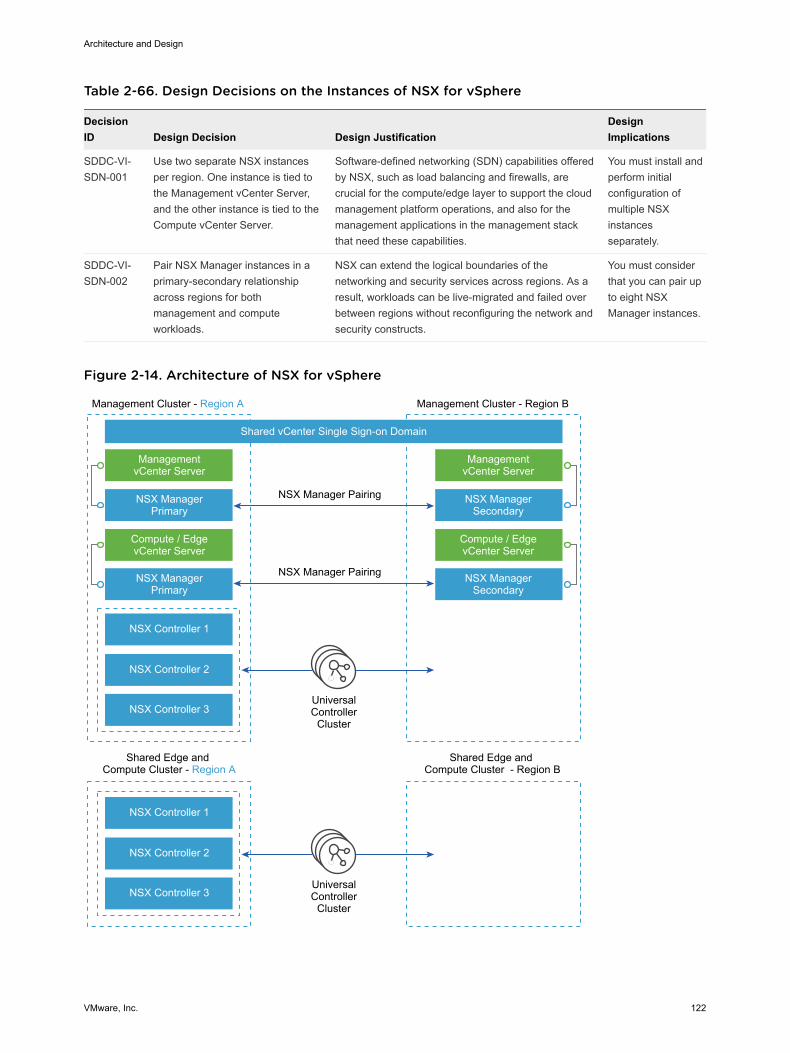
Table 2-66. Design Decisions on the Instances of NSX for vSphere
DecisionID Design Decision Design Justification
DesignImplications
SDDC-VI-SDN-001
Use two separate NSX instancesper region. One instance is tied tothe Management vCenter Server,and the other instance is tied to theCompute vCenter Server.
Software-defined networking (SDN) capabilities offeredby NSX, such as load balancing and firewalls, arecrucial for the compute/edge layer to support the cloudmanagement platform operations, and also for themanagement applications in the management stackthat need these capabilities.
You must install andperform initialconfiguration ofmultiple NSXinstancesseparately.
SDDC-VI-SDN-002
Pair NSX Manager instances in aprimary-secondary relationshipacross regions for bothmanagement and computeworkloads.
NSX can extend the logical boundaries of thenetworking and security services across regions. As aresult, workloads can be live-migrated and failed overbetween regions without reconfiguring the network andsecurity constructs.
You must considerthat you can pair upto eight NSXManager instances.
Figure 2-14. Architecture of NSX for vSphere
UniversalController
Cluster
UniversalController
Cluster
Management Cluster - Region A
Shared Edge and Compute Cluster - Region A
Shared Edge and Compute Cluster - Region B
Shared vCenter Single Sign-on Domain
NSX Manager Pairing
NSX Manager Pairing
ManagementvCenter Server
NSX ManagerPrimary
NSX ManagerPrimary
NSX Controller 1
NSX Controller 2
NSX Controller 3
NSX Controller 1
NSX Controller 2
NSX Controller 3
Compute / EdgevCenter Server
Management Cluster - Region B
ManagementvCenter Server
NSX ManagerSecondary
NSX ManagerSecondary
Compute / EdgevCenter Server
Architecture and Design
VMware, Inc. 122
NSX Components The following sections describe the components in the solution and how they are relevant to the networkvirtualization design.
Usage Model
The cloud management platform (CMP), represented by vRealize Automation in VMware ValidatedDesign, can use NSX by using the NSX RESTful API and the vSphere Client.
Cloud ManagementPlatform
In vRealize Automation, NSX offers self-service provisioning of virtualnetworks and related features from a service portal. See CloudManagement Design .
RESTful API n A client can read an object by making an HTTP GET request to theresource URL of the object.
n A client can create or modify an object by using an HTTP PUT or POSTrequest that includes a new or changed XML document for the object.
n A client can delete an object with an HTTP DELETE request.
vSphere Client NSX Manager provides a networking and security plug-in in the vSphereClient. This plug-in provides an interface for using virtualized networkingfrom NSX Manager for users with sufficient privileges.
Table 2-67. Design Decisions on the NSX Consumption Method
DecisionID Design Decision Design Justification Design Implications
SDDC-VI-SDN-003
For the shared edge and computecluster NSX instance, end-useraccess is accomplished by usingvRealize Automation services.Administrators use both thevSphere Web Client or vSphereClient and the NSX REST API.
vRealize Automation services are used for thecustomer-facing portal. The vSphere Client andvSphere Web Client consume NSX for vSphereresources through the Network and Securityplug-in. The NSX REST API offers the potentialof scripting repeating actions and operations.
End-users typically interactonly indirectly with NSXfrom the vRealizeAutomation portal.Administrators interact withNSX from the vSphereClient or vSphere WebClient, and API.
SDDC-VI-SDN-004
For the NSX instance for themanagement cluster, consumptionis only by provider staff using thevSphere Client or vSphere WebClient and the API.
Ensures that infrastructure components are notmodified by tenants or non-provider staff.
Tenants do not haveaccess to the managementstack workloads.
NSX Manager
NSX Manager implements the centralized management plane for NSX and has a one-to-one relationshipto vCenter Server.
Architecture and Design
VMware, Inc. 123
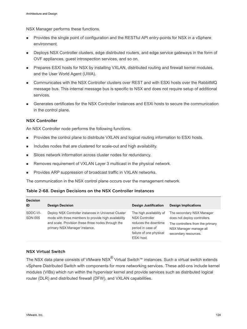
NSX Manager performs these functions.
n Provides the single point of configuration and the RESTful API entry-points for NSX in a vSphereenvironment.
n Deploys NSX Controller clusters, edge distributed routers, and edge service gateways in the form ofOVF appliances, guest introspection services, and so on.
n Prepares ESXi hosts for NSX by installing VXLAN, distributed routing and firewall kernel modules,and the User World Agent (UWA).
n Communicates with the NSX Controller clusters over REST and with ESXi hosts over the RabbitMQmessage bus. This internal message bus is specific to NSX and does not require setup of additionalservices.
n Generates certificates for the NSX Controller instances and ESXi hosts to secure the communicationin the control plane.
NSX Controller
An NSX Controller node performs the following functions.
n Provides the control plane to distribute VXLAN and logical routing information to ESXi hosts.
n Includes nodes that are clustered for scale-out and high availability.
n Slices network information across cluster nodes for redundancy.
n Removes requirement of VXLAN Layer 3 multicast in the physical network.
n Provides ARP suppression of broadcast traffic in VXLAN networks.
The communication in the NSX control plane occurs over the management network.
Table 2-68. Design Decisions on the NSX Controller Instances
DecisionID Design Decision Design Justification Design Implications
SDDC-VI-SDN-005
Deploy NSX Controller instances in Universal Clustermode with three members to provide high availabilityand scale. Provision these three nodes through theprimary NSX Manager instance.
The high availability ofNSX Controllerreduces the downtimeperiod in case offailure of one physicalESXi host.
The secondary NSX Managerdoes not deploy controllers.
The controllers from the primaryNSX Manager manage allsecondary resources.
NSX Virtual Switch
The NSX data plane consists of VMware NSX® Virtual Switch™ instances. Such a virtual switch extendsvSphere Distributed Switch with components for more networking services. These add-ons include kernelmodules (VIBs) which run within the hypervisor kernel and provide services such as distributed logicalrouter (DLR) and distributed firewall (DFW), and VXLAN capabilities.
Architecture and Design
VMware, Inc. 124
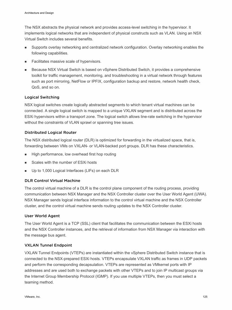
The NSX abstracts the physical network and provides access-level switching in the hypervisor. Itimplements logical networks that are independent of physical constructs such as VLAN. Using an NSXVirtual Switch includes several benefits.
n Supports overlay networking and centralized network configuration. Overlay networking enables thefollowing capabilities.
n Facilitates massive scale of hypervisors.
n Because NSX Virtual Switch is based on vSphere Distributed Switch, it provides a comprehensivetoolkit for traffic management, monitoring, and troubleshooting in a virtual network through featuressuch as port mirroring, NetFlow or IPFIX, configuration backup and restore, network health check,QoS, and so on.
Logical Switching
NSX logical switches create logically abstracted segments to which tenant virtual machines can beconnected. A single logical switch is mapped to a unique VXLAN segment and is distributed across theESXi hypervisors within a transport zone. The logical switch allows line-rate switching in the hypervisorwithout the constraints of VLAN sprawl or spanning tree issues.
Distributed Logical Router
The NSX distributed logical router (DLR) is optimized for forwarding in the virtualized space, that is,forwarding between VMs on VXLAN- or VLAN-backed port groups. DLR has these characteristics.
n High performance, low overhead first hop routing
n Scales with the number of ESXi hosts
n Up to 1,000 Logical Interfaces (LIFs) on each DLR
DLR Control Virtual Machine
The control virtual machine of a DLR is the control plane component of the routing process, providingcommunication between NSX Manager and the NSX Controller cluster over the User World Agent (UWA).NSX Manager sends logical interface information to the control virtual machine and the NSX Controllercluster, and the control virtual machine sends routing updates to the NSX Controller cluster.
User World Agent
The User World Agent is a TCP (SSL) client that facilitates the communication between the ESXi hostsand the NSX Controller instances, and the retrieval of information from NSX Manager via interaction withthe message bus agent.
VXLAN Tunnel Endpoint
VXLAN Tunnel Endpoints (VTEPs) are instantiated within the vSphere Distributed Switch instance that isconnected to the NSX-prepared ESXi hosts. VTEPs encapsulate VXLAN traffic as frames in UDP packetsand perform the corresponding decapsulation. VTEPs are represented as VMkernel ports with IPaddresses and are used both to exchange packets with other VTEPs and to join IP multicast groups viathe Internet Group Membership Protocol (IGMP). If you use multiple VTEPs, then you must select ateaming method.
Architecture and Design
VMware, Inc. 125
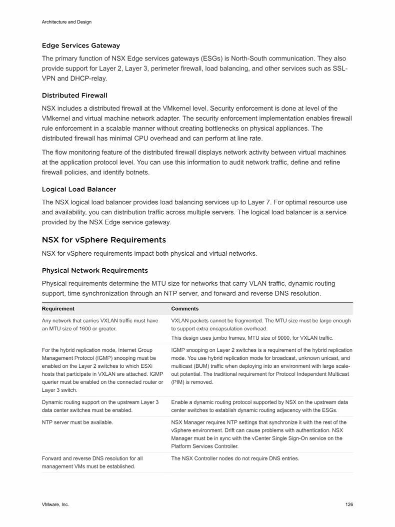
Edge Services Gateway
The primary function of NSX Edge services gateways (ESGs) is North-South communication. They alsoprovide support for Layer 2, Layer 3, perimeter firewall, load balancing, and other services such as SSL-VPN and DHCP-relay.
Distributed Firewall
NSX includes a distributed firewall at the VMkernel level. Security enforcement is done at level of theVMkernel and virtual machine network adapter. The security enforcement implementation enables firewallrule enforcement in a scalable manner without creating bottlenecks on physical appliances. Thedistributed firewall has minimal CPU overhead and can perform at line rate.
The flow monitoring feature of the distributed firewall displays network activity between virtual machinesat the application protocol level. You can use this information to audit network traffic, define and refinefirewall policies, and identify botnets.
Logical Load Balancer
The NSX logical load balancer provides load balancing services up to Layer 7. For optimal resource useand availability, you can distribution traffic across multiple servers. The logical load balancer is a serviceprovided by the NSX Edge service gateway.
NSX for vSphere Requirements NSX for vSphere requirements impact both physical and virtual networks.
Physical Network Requirements
Physical requirements determine the MTU size for networks that carry VLAN traffic, dynamic routingsupport, time synchronization through an NTP server, and forward and reverse DNS resolution.
Requirement Comments
Any network that carries VXLAN traffic must havean MTU size of 1600 or greater.
VXLAN packets cannot be fragmented. The MTU size must be large enoughto support extra encapsulation overhead.
This design uses jumbo frames, MTU size of 9000, for VXLAN traffic.
For the hybrid replication mode, Internet GroupManagement Protocol (IGMP) snooping must beenabled on the Layer 2 switches to which ESXihosts that participate in VXLAN are attached. IGMPquerier must be enabled on the connected router orLayer 3 switch.
IGMP snooping on Layer 2 switches is a requirement of the hybrid replicationmode. You use hybrid replication mode for broadcast, unknown unicast, andmulticast (BUM) traffic when deploying into an environment with large scale-out potential. The traditional requirement for Protocol Independent Multicast(PIM) is removed.
Dynamic routing support on the upstream Layer 3data center switches must be enabled.
Enable a dynamic routing protocol supported by NSX on the upstream datacenter switches to establish dynamic routing adjacency with the ESGs.
NTP server must be available. NSX Manager requires NTP settings that synchronize it with the rest of thevSphere environment. Drift can cause problems with authentication. NSXManager must be in sync with the vCenter Single Sign-On service on thePlatform Services Controller.
Forward and reverse DNS resolution for allmanagement VMs must be established.
The NSX Controller nodes do not require DNS entries.
Architecture and Design
VMware, Inc. 126
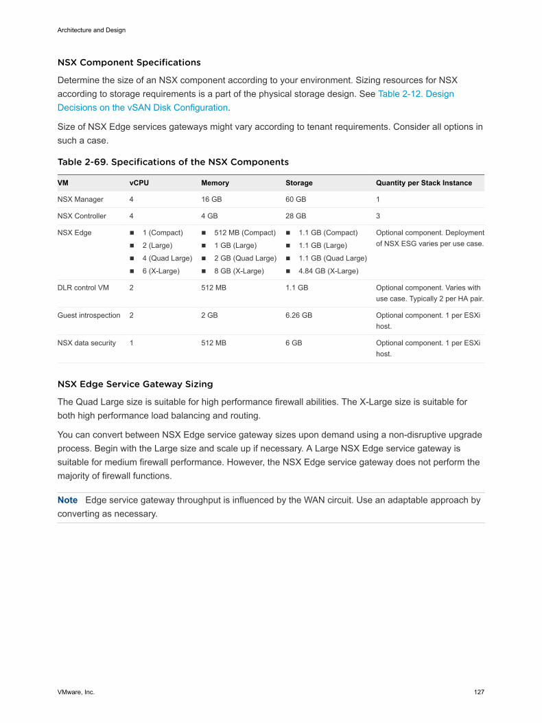
NSX Component Specifications
Determine the size of an NSX component according to your environment. Sizing resources for NSXaccording to storage requirements is a part of the physical storage design. See Table 2-12. DesignDecisions on the vSAN Disk Configuration.
Size of NSX Edge services gateways might vary according to tenant requirements. Consider all options insuch a case.
Table 2-69. Specifications of the NSX Components
VM vCPU Memory Storage Quantity per Stack Instance
NSX Manager 4 16 GB 60 GB 1
NSX Controller 4 4 GB 28 GB 3
NSX Edge n 1 (Compact)
n 2 (Large)
n 4 (Quad Large)
n 6 (X-Large)
n 512 MB (Compact)
n 1 GB (Large)
n 2 GB (Quad Large)
n 8 GB (X-Large)
n 1.1 GB (Compact)
n 1.1 GB (Large)
n 1.1 GB (Quad Large)
n 4.84 GB (X-Large)
Optional component. Deploymentof NSX ESG varies per use case.
DLR control VM 2 512 MB 1.1 GB Optional component. Varies withuse case. Typically 2 per HA pair.
Guest introspection 2 2 GB 6.26 GB Optional component. 1 per ESXihost.
NSX data security 1 512 MB 6 GB Optional component. 1 per ESXihost.
NSX Edge Service Gateway Sizing
The Quad Large size is suitable for high performance firewall abilities. The X-Large size is suitable forboth high performance load balancing and routing.
You can convert between NSX Edge service gateway sizes upon demand using a non-disruptive upgradeprocess. Begin with the Large size and scale up if necessary. A Large NSX Edge service gateway issuitable for medium firewall performance. However, the NSX Edge service gateway does not perform themajority of firewall functions.
Note Edge service gateway throughput is influenced by the WAN circuit. Use an adaptable approach byconverting as necessary.
Architecture and Design
VMware, Inc. 127
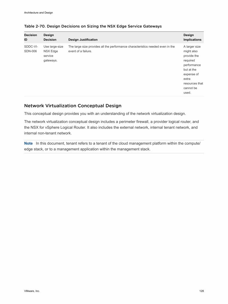
Table 2-70. Design Decisions on Sizing the NSX Edge Service Gateways
DecisionID
DesignDecision Design Justification
DesignImplications
SDDC-VI-SDN-006
Use large-sizeNSX Edgeservicegateways.
The large size provides all the performance characteristics needed even in theevent of a failure.
A larger sizemight alsoprovide therequiredperformancebut at theexpense ofextraresources thatcannot beused.
Network Virtualization Conceptual Design This conceptual design provides you with an understanding of the network virtualization design.
The network virtualization conceptual design includes a perimeter firewall, a provider logical router, andthe NSX for vSphere Logical Router. It also includes the external network, internal tenant network, andinternal non-tenant network.
Note In this document, tenant refers to a tenant of the cloud management platform within the compute/edge stack, or to a management application within the management stack.
Architecture and Design
VMware, Inc. 128
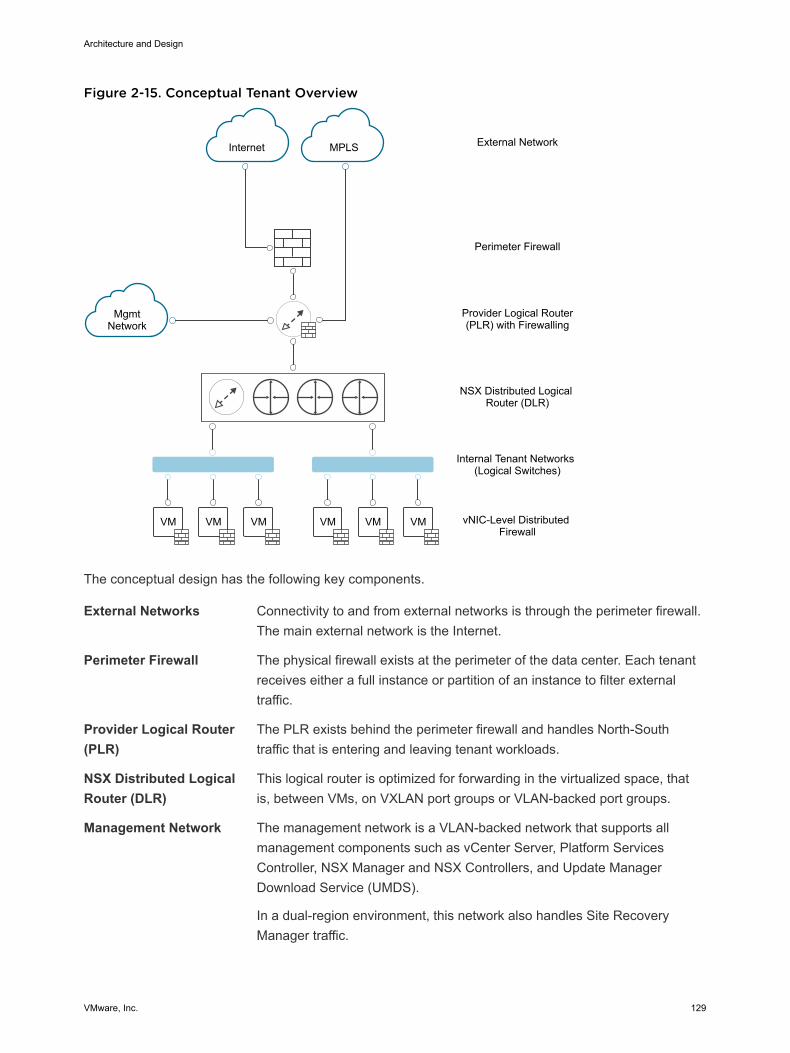
Figure 2-15. Conceptual Tenant Overview
VM VMVM VM VMVM
Internet MPLS
MgmtNetwork
External Network
Perimeter Firewall
Provider Logical Router(PLR) with Firewalling
NSX Distributed Logical Router (DLR)
Internal Tenant Networks (Logical Switches)
vNIC-Level Distributed Firewall
The conceptual design has the following key components.
External Networks Connectivity to and from external networks is through the perimeter firewall.The main external network is the Internet.
Perimeter Firewall The physical firewall exists at the perimeter of the data center. Each tenantreceives either a full instance or partition of an instance to filter externaltraffic.
Provider Logical Router(PLR)
The PLR exists behind the perimeter firewall and handles North-Southtraffic that is entering and leaving tenant workloads.
NSX Distributed LogicalRouter (DLR)
This logical router is optimized for forwarding in the virtualized space, thatis, between VMs, on VXLAN port groups or VLAN-backed port groups.
Management Network The management network is a VLAN-backed network that supports allmanagement components such as vCenter Server, Platform ServicesController, NSX Manager and NSX Controllers, and Update ManagerDownload Service (UMDS).
In a dual-region environment, this network also handles Site RecoveryManager traffic.
Architecture and Design
VMware, Inc. 129
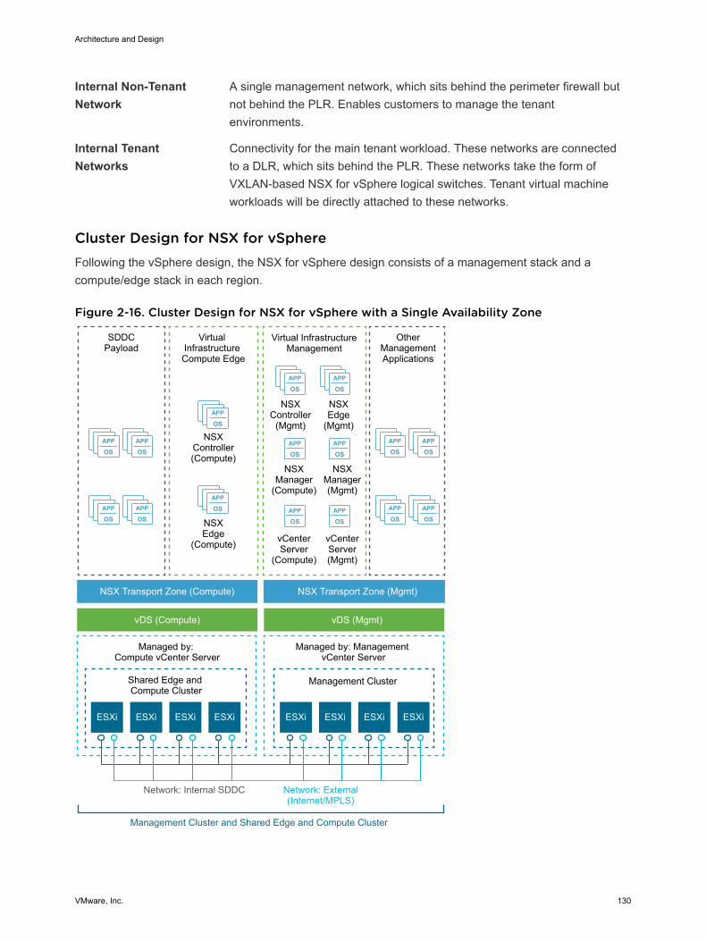
Internal Non-TenantNetwork
A single management network, which sits behind the perimeter firewall butnot behind the PLR. Enables customers to manage the tenantenvironments.
Internal TenantNetworks
Connectivity for the main tenant workload. These networks are connectedto a DLR, which sits behind the PLR. These networks take the form ofVXLAN-based NSX for vSphere logical switches. Tenant virtual machineworkloads will be directly attached to these networks.
Cluster Design for NSX for vSphere Following the vSphere design, the NSX for vSphere design consists of a management stack and acompute/edge stack in each region.
Figure 2-16. Cluster Design for NSX for vSphere with a Single Availability Zone
APP
OSAPP
OS
APP
OSAPP
OS
APP
OSAPP
OS
APP
OSAPP
OS
APP
OS
APP
OS
APP
OSAPP
OS
APP
OSAPP
OS
APP
OSAPP
OS
Virtual InfrastructureManagement
NSXController
(Mgmt)
OtherManagementApplications
NSXEdge
(Mgmt)
NSXManager(Mgmt)
NSXManager
(Compute)
NSXEdge
(Compute)
NSXController(Compute)
ESXi ESXi ESXi ESXi ESXi ESXi
SDDCPayload
Virtual Infrastructure Compute Edge
NSX Transport Zone (Compute)
vDS (Compute) vDS (Mgmt)
NSX Transport Zone (Mgmt)
Shared Edge and Compute Cluster
Management Cluster
Managed by: Compute vCenter Server
Managed by: Management vCenter Server
Network: External(Internet/MPLS)
Network: Internal SDDC
Management Cluster and Shared Edge and Compute Cluster
vCenterServer(Mgmt)
vCenterServer
(Compute)
ESXi ESXi
Architecture and Design
VMware, Inc. 130
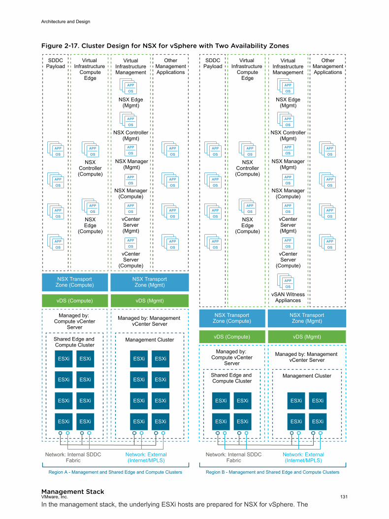
Figure 2-17. Cluster Design for NSX for vSphere with Two Availability Zones
APP
OS
APP
OS
APP
OS
APP
OSAPP
OS
APP
OS
APP
OS
APP
OS
ESXi
APP
OS
APP
OS
APP
OS
APP
OS
APP
OS
APP
OS
APP
OS
APP
OS
APP
OS
APP
OS
APP
OS
APP
OS
APP
OS
APP
OS
APP
OS
APP
OS
APP
OS
APP
OS
APP
OS
APP
OS
APP
OSAPP
OS
APP
OS
APP
OS
APP
OS
VirtualInfrastructureManagement
NSX Controller(Mgmt)
OtherManagementApplications
NSX Edge(Mgmt)
NSX Manager(Mgmt)
NSX Manager(Compute)
NSXEdge
(Compute)
NSXController(Compute)
ESXi
ESXi ESXi
SDDCPayload
Virtual Infrastructure
ComputeEdge
NSX TransportZone (Compute)
vDS (Compute) vDS (Mgmt)
NSX TransportZone (Mgmt)
Shared Edge and Compute Cluster
Management Cluster
Managed by: Compute vCenter
Server
Managed by: Management vCenter Server
Network: External(Internet/MPLS)
Network: Internal SDDCFabric
Region A - Management and Shared Edge and Compute Clusters
vCenterServer(Mgmt)
vCenterServer
(Compute)
ESXiESXi
ESXi ESXi
ESXiESXi
ESXi ESXi
ESXiESXi
ESXi ESXi
ESXi
VirtualInfrastructureManagement
NSX Controller(Mgmt)
OtherManagementApplications
NSX Edge(Mgmt)
NSX Manager(Mgmt)
NSX Manager(Compute)
NSXEdge
(Compute)
NSXController(Compute)
ESXi
ESXi ESXi
SDDCPayload
Virtual Infrastructure
ComputeEdge
NSX TransportZone (Compute)
vDS (Compute) vDS (Mgmt)
NSX TransportZone (Mgmt)
Shared Edge and Compute Cluster
Management Cluster
Managed by: Compute vCenter
Server
Managed by: Management vCenter Server
Network: External(Internet/MPLS)
Network: Internal SDDCFabric
Region B - Management and Shared Edge and Compute Clusters
vCenterServer(Mgmt)
vCenterServer
(Compute)
ESXiESXi
ESXi ESXi
vSAN WitnessAppliances
Management Stack
In the management stack, the underlying ESXi hosts are prepared for NSX for vSphere. The
Architecture and Design
VMware, Inc. 131
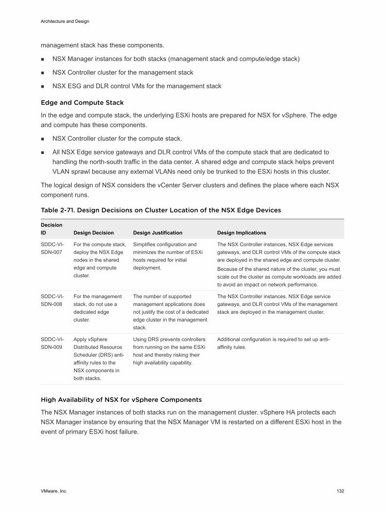
management stack has these components.
n NSX Manager instances for both stacks (management stack and compute/edge stack)
n NSX Controller cluster for the management stack
n NSX ESG and DLR control VMs for the management stack
Edge and Compute Stack
In the edge and compute stack, the underlying ESXi hosts are prepared for NSX for vSphere. The edgeand compute has these components.
n NSX Controller cluster for the compute stack.
n All NSX Edge service gateways and DLR control VMs of the compute stack that are dedicated tohandling the north-south traffic in the data center. A shared edge and compute stack helps preventVLAN sprawl because any external VLANs need only be trunked to the ESXi hosts in this cluster.
The logical design of NSX considers the vCenter Server clusters and defines the place where each NSXcomponent runs.
Table 2-71. Design Decisions on Cluster Location of the NSX Edge Devices
DecisionID Design Decision Design Justification Design Implications
SDDC-VI-SDN-007
For the compute stack,deploy the NSX Edgenodes in the sharededge and computecluster.
Simplifies configuration andminimizes the number of ESXihosts required for initialdeployment.
The NSX Controller instances, NSX Edge servicesgateways, and DLR control VMs of the compute stackare deployed in the shared edge and compute cluster.
Because of the shared nature of the cluster, you mustscale out the cluster as compute workloads are addedto avoid an impact on network performance.
SDDC-VI-SDN-008
For the managementstack, do not use adedicated edgecluster.
The number of supportedmanagement applications doesnot justify the cost of a dedicatededge cluster in the managementstack.
The NSX Controller instances, NSX Edge servicegateways, and DLR control VMs of the managementstack are deployed in the management cluster.
SDDC-VI-SDN-009
Apply vSphereDistributed ResourceScheduler (DRS) anti-affinity rules to theNSX components inboth stacks.
Using DRS prevents controllersfrom running on the same ESXihost and thereby risking theirhigh availability capability.
Additional configuration is required to set up anti-affinity rules.
High Availability of NSX for vSphere Components
The NSX Manager instances of both stacks run on the management cluster. vSphere HA protects eachNSX Manager instance by ensuring that the NSX Manager VM is restarted on a different ESXi host in theevent of primary ESXi host failure.
Architecture and Design
VMware, Inc. 132
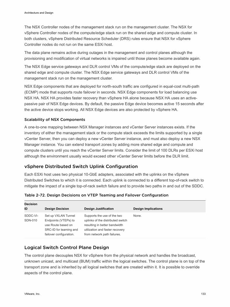
The NSX Controller nodes of the management stack run on the management cluster. The NSX forvSphere Controller nodes of the compute/edge stack run on the shared edge and compute cluster. Inboth clusters, vSphere Distributed Resource Scheduler (DRS) rules ensure that NSX for vSphereController nodes do not run on the same ESXi host.
The data plane remains active during outages in the management and control planes although theprovisioning and modification of virtual networks is impaired until those planes become available again.
The NSX Edge service gateways and DLR control VMs of the compute/edge stack are deployed on theshared edge and compute cluster. The NSX Edge service gateways and DLR control VMs of themanagement stack run on the management cluster.
NSX Edge components that are deployed for north-south traffic are configured in equal-cost multi-path(ECMP) mode that supports route failover in seconds. NSX Edge components for load balancing useNSX HA. NSX HA provides faster recovery than vSphere HA alone because NSX HA uses an active-passive pair of NSX Edge devices. By default, the passive Edge device becomes active 15 seconds afterthe active device stops working. All NSX Edge devices are also protected by vSphere HA.
Scalability of NSX Components
A one-to-one mapping between NSX Manager instances and vCenter Server instances exists. If theinventory of either the management stack or the compute stack exceeds the limits supported by a singlevCenter Server, then you can deploy a new vCenter Server instance, and must also deploy a new NSXManager instance. You can extend transport zones by adding more shared edge and compute andcompute clusters until you reach the vCenter Server limits. Consider the limit of 100 DLRs per ESXi hostalthough the environment usually would exceed other vCenter Server limits before the DLR limit.
vSphere Distributed Switch Uplink Configuration Each ESXi host uses two physical 10-GbE adapters, associated with the uplinks on the vSphereDistributed Switches to which it is connected. Each uplink is connected to a different top-of-rack switch tomitigate the impact of a single top-of-rack switch failure and to provide two paths in and out of the SDDC.
Table 2-72. Design Decisions on VTEP Teaming and Failover Configuration
DecisionID Design Decision Design Justification Design Implications
SDDC-VI-SDN-010
Set up VXLAN TunnelEndpoints (VTEPs) touse Route based onSRC-ID for teaming andfailover configuration.
Supports the use of the twouplinks of the distributed switchresulting in better bandwidthutilization and faster recoveryfrom network path failures.
None.
Logical Switch Control Plane Design The control plane decouples NSX for vSphere from the physical network and handles the broadcast,unknown unicast, and multicast (BUM) traffic within the logical switches. The control plane is on top of thetransport zone and is inherited by all logical switches that are created within it. It is possible to overrideaspects of the control plane.
Architecture and Design
VMware, Inc. 133
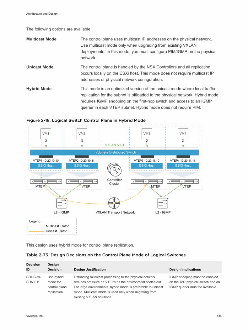
The following options are available.
Multicast Mode The control plane uses multicast IP addresses on the physical network.Use multicast mode only when upgrading from existing VXLANdeployments. In this mode, you must configure PIM/IGMP on the physicalnetwork.
Unicast Mode The control plane is handled by the NSX Controllers and all replicationoccurs locally on the ESXi host. This mode does not require multicast IPaddresses or physical network configuration.
Hybrid Mode This mode is an optimized version of the unicast mode where local trafficreplication for the subnet is offloaded to the physical network. Hybrid moderequires IGMP snooping on the first-hop switch and access to an IGMPquerier in each VTEP subnet. Hybrid mode does not require PIM.
Figure 2-18. Logical Switch Control Plane in Hybrid Mode
VM1 VM2
vSphere Distributed Switch
ESXi Host
VXLAN 5001
VTEP1 10.20.10.10
ESXi HostVTEP2 10.20.10.11
VM3
ESXi HostVTEP3 10.20.11.10
VM4
ESXi HostVTEP4 10.20.11.11
MTEP VTEP MTEP VTEP
L2 - IGMP L2 - IGMP
Multicast TrafficUnicast Traffic
ControllerCluster
Legend:
VXLAN Transport Network
This design uses hybrid mode for control plane replication.
Table 2-73. Design Decisions on the Control Plane Mode of Logical Switches
DecisionID
DesignDecision Design Justification Design Implications
SDDC-VI-SDN-011
Use hybridmode forcontrol planereplication.
Offloading multicast processing to the physical networkreduces pressure on VTEPs as the environment scales out.For large environments, hybrid mode is preferable to unicastmode. Multicast mode is used only when migrating fromexisting VXLAN solutions.
IGMP snooping must be enabledon the ToR physical switch and anIGMP querier must be available.
Architecture and Design
VMware, Inc. 134
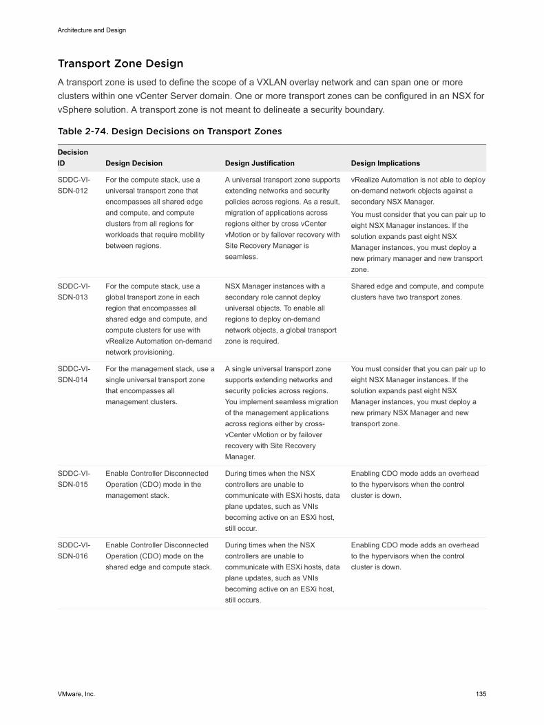
Transport Zone Design A transport zone is used to define the scope of a VXLAN overlay network and can span one or moreclusters within one vCenter Server domain. One or more transport zones can be configured in an NSX forvSphere solution. A transport zone is not meant to delineate a security boundary.
Table 2-74. Design Decisions on Transport Zones
DecisionID Design Decision Design Justification Design Implications
SDDC-VI-SDN-012
For the compute stack, use auniversal transport zone thatencompasses all shared edgeand compute, and computeclusters from all regions forworkloads that require mobilitybetween regions.
A universal transport zone supportsextending networks and securitypolicies across regions. As a result,migration of applications acrossregions either by cross vCentervMotion or by failover recovery withSite Recovery Manager isseamless.
vRealize Automation is not able to deployon-demand network objects against asecondary NSX Manager.
You must consider that you can pair up toeight NSX Manager instances. If thesolution expands past eight NSXManager instances, you must deploy anew primary manager and new transportzone.
SDDC-VI-SDN-013
For the compute stack, use aglobal transport zone in eachregion that encompasses allshared edge and compute, andcompute clusters for use withvRealize Automation on-demandnetwork provisioning.
NSX Manager instances with asecondary role cannot deployuniversal objects. To enable allregions to deploy on-demandnetwork objects, a global transportzone is required.
Shared edge and compute, and computeclusters have two transport zones.
SDDC-VI-SDN-014
For the management stack, use asingle universal transport zonethat encompasses allmanagement clusters.
A single universal transport zonesupports extending networks andsecurity policies across regions.You implement seamless migrationof the management applicationsacross regions either by cross-vCenter vMotion or by failoverrecovery with Site RecoveryManager.
You must consider that you can pair up toeight NSX Manager instances. If thesolution expands past eight NSXManager instances, you must deploy anew primary NSX Manager and newtransport zone.
SDDC-VI-SDN-015
Enable Controller DisconnectedOperation (CDO) mode in themanagement stack.
During times when the NSXcontrollers are unable tocommunicate with ESXi hosts, dataplane updates, such as VNIsbecoming active on an ESXi host,still occur.
Enabling CDO mode adds an overheadto the hypervisors when the controlcluster is down.
SDDC-VI-SDN-016
Enable Controller DisconnectedOperation (CDO) mode on theshared edge and compute stack.
During times when the NSXcontrollers are unable tocommunicate with ESXi hosts, dataplane updates, such as VNIsbecoming active on an ESXi host,still occurs.
Enabling CDO mode adds an overheadto the hypervisors when the controlcluster is down.
Architecture and Design
VMware, Inc. 135
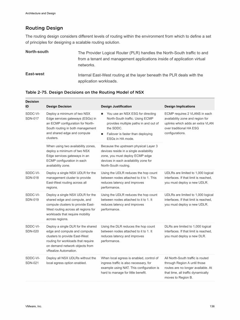
Routing Design The routing design considers different levels of routing within the environment from which to define a setof principles for designing a scalable routing solution.
North-south The Provider Logical Router (PLR) handles the North-South traffic to andfrom a tenant and management applications inside of application virtualnetworks.
East-west Internal East-West routing at the layer beneath the PLR deals with theapplication workloads.
Table 2-75. Design Decisions on the Routing Model of NSX
DecisionID Design Decision Design Justification Design Implications
SDDC-VI-SDN-017
Deploy a minimum of two NSXEdge services gateways (ESGs) inan ECMP configuration for North-South routing in both managementand shared edge and computeclusters.
n You use an NSX ESG for directingNorth-South traffic. Using ECMPprovides multiple paths in and out ofthe SDDC.
n Failover is faster than deployingESGs in HA mode.
ECMP requires 2 VLANS in eachavailability zone and region foruplinks which adds an extra VLANover traditional HA ESGconfigurations.
When using two availability zones,deploy a minimum of two NSXEdge services gateways in anECMP configuration in eachavailability zone.
Because the upstream physical Layer 3devices reside in a single availabilityzone, you must deploy ECMP edgedevices in each availability zone forNorth-South routing.
SDDC-VI-SDN-018
Deploy a single NSX UDLR for themanagement cluster to provideEast-West routing across allregions.
Using the UDLR reduces the hop countbetween nodes attached to it to 1. Thisreduces latency and improvesperformance.
UDLRs are limited to 1,000 logicalinterfaces. If that limit is reached,you must deploy a new UDLR.
SDDC-VI-SDN-019
Deploy a single NSX UDLR for theshared edge and compute, andcompute clusters to provide East-West routing across all regions forworkloads that require mobilityacross regions.
Using the UDLR reduces the hop countbetween nodes attached to it to 1. Itreduces latency and improvesperformance.
UDLRs are limited to 1,000 logicalinterfaces. If that limit is reached,you must deploy a new UDLR.
SDDC-VI-SDN-020
Deploy a single DLR for the sharededge and compute and computeclusters to provide East-Westrouting for workloads that requireon demand network objects fromvRealize Automation.
Using the DLR reduces the hop countbetween nodes attached to it to 1. Itreduces latency and improvesperformance.
DLRs are limited to 1,000 logicalinterfaces. If that limit is reached,you must deploy a new DLR.
SDDC-VI-SDN-021
Deploy all NSX UDLRs without thelocal egress option enabled.
When local egress is enabled, control ofingress traffic is also necessary, forexample using NAT. This configuration ishard to manage for little benefit.
All North-South traffic is routedthrough Region A until thoseroutes are no longer available. Atthat time, all traffic dynamicallymoves to Region B.
Architecture and Design
VMware, Inc. 136
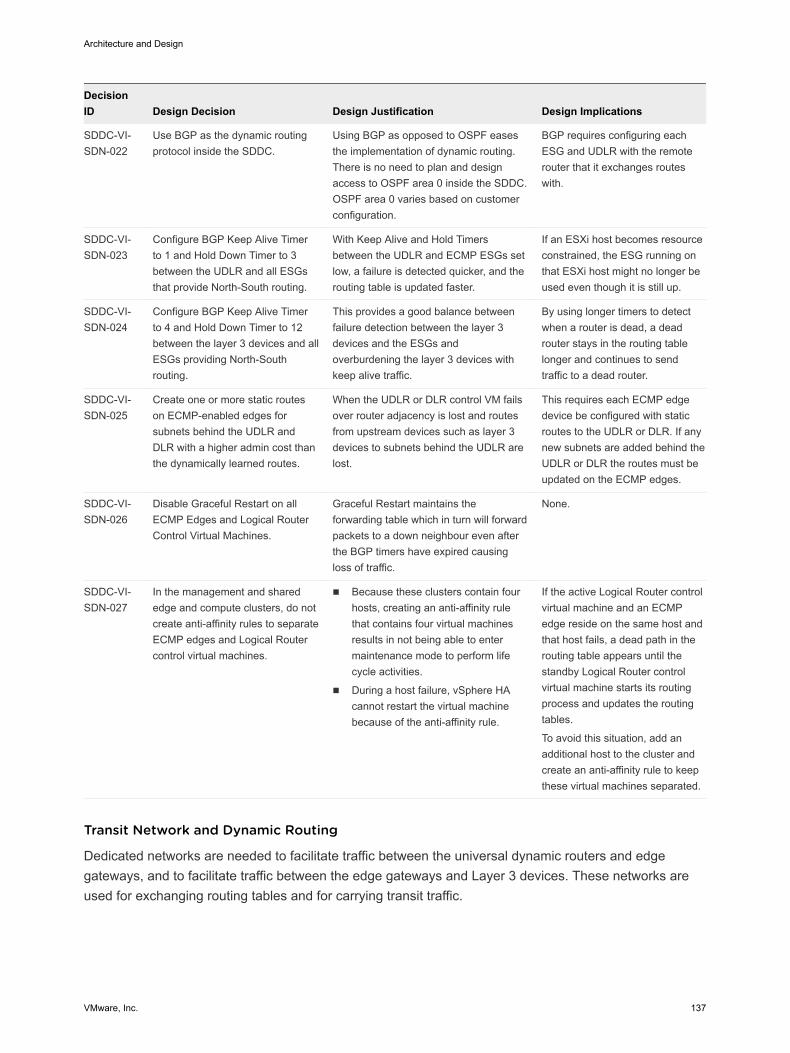
DecisionID Design Decision Design Justification Design Implications
SDDC-VI-SDN-022
Use BGP as the dynamic routingprotocol inside the SDDC.
Using BGP as opposed to OSPF easesthe implementation of dynamic routing.There is no need to plan and designaccess to OSPF area 0 inside the SDDC.OSPF area 0 varies based on customerconfiguration.
BGP requires configuring eachESG and UDLR with the remoterouter that it exchanges routeswith.
SDDC-VI-SDN-023
Configure BGP Keep Alive Timerto 1 and Hold Down Timer to 3between the UDLR and all ESGsthat provide North-South routing.
With Keep Alive and Hold Timersbetween the UDLR and ECMP ESGs setlow, a failure is detected quicker, and therouting table is updated faster.
If an ESXi host becomes resourceconstrained, the ESG running onthat ESXi host might no longer beused even though it is still up.
SDDC-VI-SDN-024
Configure BGP Keep Alive Timerto 4 and Hold Down Timer to 12between the layer 3 devices and allESGs providing North-Southrouting.
This provides a good balance betweenfailure detection between the layer 3devices and the ESGs andoverburdening the layer 3 devices withkeep alive traffic.
By using longer timers to detectwhen a router is dead, a deadrouter stays in the routing tablelonger and continues to sendtraffic to a dead router.
SDDC-VI-SDN-025
Create one or more static routeson ECMP-enabled edges forsubnets behind the UDLR andDLR with a higher admin cost thanthe dynamically learned routes.
When the UDLR or DLR control VM failsover router adjacency is lost and routesfrom upstream devices such as layer 3devices to subnets behind the UDLR arelost.
This requires each ECMP edgedevice be configured with staticroutes to the UDLR or DLR. If anynew subnets are added behind theUDLR or DLR the routes must beupdated on the ECMP edges.
SDDC-VI-SDN-026
Disable Graceful Restart on allECMP Edges and Logical RouterControl Virtual Machines.
Graceful Restart maintains theforwarding table which in turn will forwardpackets to a down neighbour even afterthe BGP timers have expired causingloss of traffic.
None.
SDDC-VI-SDN-027
In the management and sharededge and compute clusters, do notcreate anti-affinity rules to separateECMP edges and Logical Routercontrol virtual machines.
n Because these clusters contain fourhosts, creating an anti-affinity rulethat contains four virtual machinesresults in not being able to entermaintenance mode to perform lifecycle activities.
n During a host failure, vSphere HAcannot restart the virtual machinebecause of the anti-affinity rule.
If the active Logical Router controlvirtual machine and an ECMPedge reside on the same host andthat host fails, a dead path in therouting table appears until thestandby Logical Router controlvirtual machine starts its routingprocess and updates the routingtables.
To avoid this situation, add anadditional host to the cluster andcreate an anti-affinity rule to keepthese virtual machines separated.
Transit Network and Dynamic Routing
Dedicated networks are needed to facilitate traffic between the universal dynamic routers and edgegateways, and to facilitate traffic between the edge gateways and Layer 3 devices. These networks areused for exchanging routing tables and for carrying transit traffic.
Architecture and Design
VMware, Inc. 137
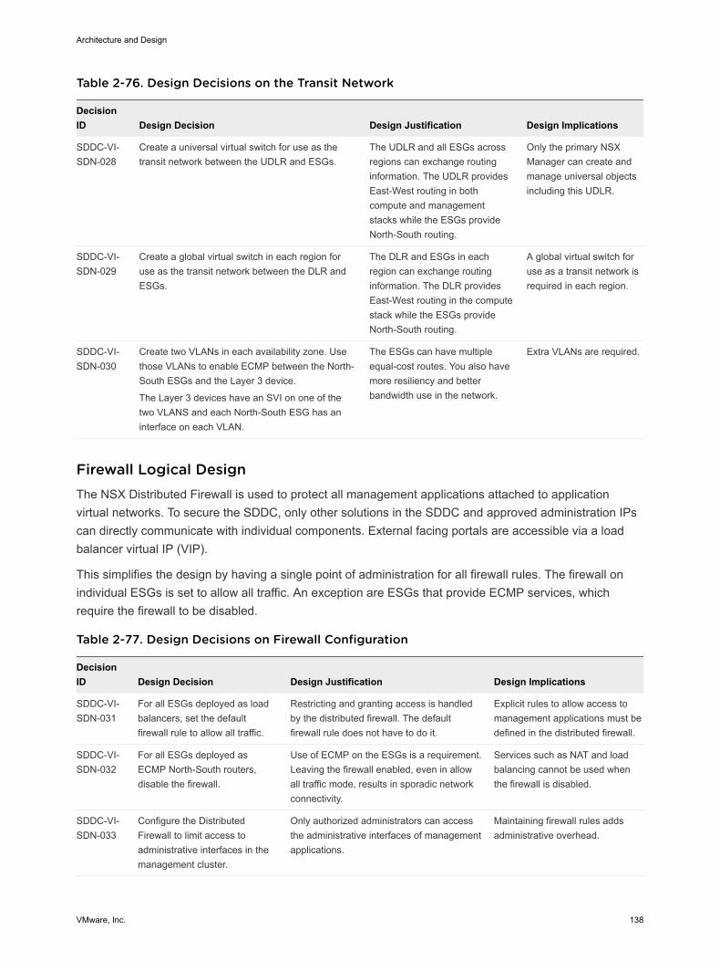
Table 2-76. Design Decisions on the Transit Network
DecisionID Design Decision Design Justification Design Implications
SDDC-VI-SDN-028
Create a universal virtual switch for use as thetransit network between the UDLR and ESGs.
The UDLR and all ESGs acrossregions can exchange routinginformation. The UDLR providesEast-West routing in bothcompute and managementstacks while the ESGs provideNorth-South routing.
Only the primary NSXManager can create andmanage universal objectsincluding this UDLR.
SDDC-VI-SDN-029
Create a global virtual switch in each region foruse as the transit network between the DLR andESGs.
The DLR and ESGs in eachregion can exchange routinginformation. The DLR providesEast-West routing in the computestack while the ESGs provideNorth-South routing.
A global virtual switch foruse as a transit network isrequired in each region.
SDDC-VI-SDN-030
Create two VLANs in each availability zone. Usethose VLANs to enable ECMP between the North-South ESGs and the Layer 3 device.
The Layer 3 devices have an SVI on one of thetwo VLANS and each North-South ESG has aninterface on each VLAN.
The ESGs can have multipleequal-cost routes. You also havemore resiliency and betterbandwidth use in the network.
Extra VLANs are required.
Firewall Logical Design The NSX Distributed Firewall is used to protect all management applications attached to applicationvirtual networks. To secure the SDDC, only other solutions in the SDDC and approved administration IPscan directly communicate with individual components. External facing portals are accessible via a loadbalancer virtual IP (VIP).
This simplifies the design by having a single point of administration for all firewall rules. The firewall onindividual ESGs is set to allow all traffic. An exception are ESGs that provide ECMP services, whichrequire the firewall to be disabled.
Table 2-77. Design Decisions on Firewall Configuration
DecisionID Design Decision Design Justification Design Implications
SDDC-VI-SDN-031
For all ESGs deployed as loadbalancers, set the defaultfirewall rule to allow all traffic.
Restricting and granting access is handledby the distributed firewall. The defaultfirewall rule does not have to do it.
Explicit rules to allow access tomanagement applications must bedefined in the distributed firewall.
SDDC-VI-SDN-032
For all ESGs deployed asECMP North-South routers,disable the firewall.
Use of ECMP on the ESGs is a requirement.Leaving the firewall enabled, even in allowall traffic mode, results in sporadic networkconnectivity.
Services such as NAT and loadbalancing cannot be used whenthe firewall is disabled.
SDDC-VI-SDN-033
Configure the DistributedFirewall to limit access toadministrative interfaces in themanagement cluster.
Only authorized administrators can accessthe administrative interfaces of managementapplications.
Maintaining firewall rules addsadministrative overhead.
Architecture and Design
VMware, Inc. 138
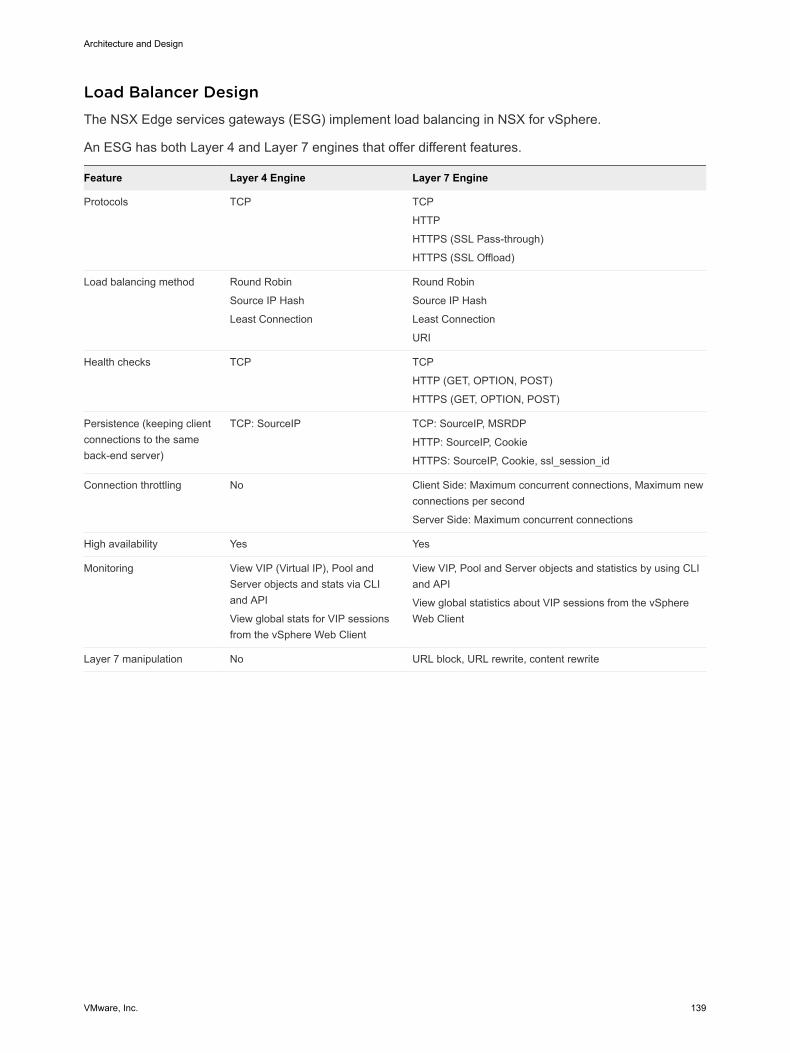
Load Balancer Design The NSX Edge services gateways (ESG) implement load balancing in NSX for vSphere.
An ESG has both Layer 4 and Layer 7 engines that offer different features.
Feature Layer 4 Engine Layer 7 Engine
Protocols TCP TCP
HTTP
HTTPS (SSL Pass-through)
HTTPS (SSL Offload)
Load balancing method Round Robin
Source IP Hash
Least Connection
Round Robin
Source IP Hash
Least Connection
URI
Health checks TCP TCP
HTTP (GET, OPTION, POST)
HTTPS (GET, OPTION, POST)
Persistence (keeping clientconnections to the sameback-end server)
TCP: SourceIP TCP: SourceIP, MSRDP
HTTP: SourceIP, Cookie
HTTPS: SourceIP, Cookie, ssl_session_id
Connection throttling No Client Side: Maximum concurrent connections, Maximum newconnections per second
Server Side: Maximum concurrent connections
High availability Yes Yes
Monitoring View VIP (Virtual IP), Pool andServer objects and stats via CLIand API
View global stats for VIP sessionsfrom the vSphere Web Client
View VIP, Pool and Server objects and statistics by using CLIand API
View global statistics about VIP sessions from the vSphereWeb Client
Layer 7 manipulation No URL block, URL rewrite, content rewrite
Architecture and Design
VMware, Inc. 139
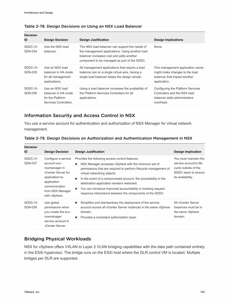
Table 2-78. Design Decisions on Using an NSX Load Balancer
DecisionID Design Decision Design Justification Design Implications
SDDC-VI-SDN-034
Use the NSX loadbalancer.
The NSX load balancer can support the needs ofthe management applications. Using another loadbalancer increases cost and adds anothercomponent to be managed as part of the SDDC.
None.
SDDC-VI-SDN-035
Use an NSX loadbalancer in HA modefor all managementapplications.
All management applications that require a loadbalancer are on a single virtual wire, having asingle load balancer keeps the design simple.
One management application ownermight make changes to the loadbalancer that impact anotherapplication.
SDDC-VI-SDN-036
Use an NSX loadbalancer in HA modefor the PlatformServices Controllers.
Using a load balancer increases the availability ofthe Platform Services Controllers for allapplications.
Configuring the Platform ServicesControllers and the NSX loadbalancer adds administrativeoverhead.
Information Security and Access Control in NSX You use a service account for authentication and authorization of NSX Manager for virtual networkmanagement.
Table 2-79. Design Decisions on Authorization and Authentication Management in NSX
DecisionID Design Decision Design Justification Design Implication
SDDC-VI-SDN-037
Configure a serviceaccount svc-nsxmanager invCenter Server forapplication-to-applicationcommunicationfrom NSX Managerwith vSphere.
Provides the following access control features:
n NSX Manager accesses vSphere with the minimum set ofpermissions that are required to perform lifecycle management ofvirtual networking objects.
n In the event of a compromised account, the accessibility in thedestination application remains restricted.
n You can introduce improved accountability in tracking request-response interactions between the components of the SDDC.
You must maintain theservice account's lifecycle outside of theSDDC stack to ensureits availability .
SDDC-VI-SDN-038
Use globalpermissions whenyou create the svc-nsxmanagerservice account invCenter Server.
n Simplifies and standardizes the deployment of the serviceaccount across all vCenter Server instances in the same vSpheredomain.
n Provides a consistent authorization layer.
All vCenter Serverinstances must be inthe same vSpheredomain.
Bridging Physical Workloads NSX for vSphere offers VXLAN to Layer 2 VLAN bridging capabilities with the data path contained entirelyin the ESXi hypervisor. The bridge runs on the ESXi host where the DLR control VM is located. Multiplebridges per DLR are supported.
Architecture and Design
VMware, Inc. 140
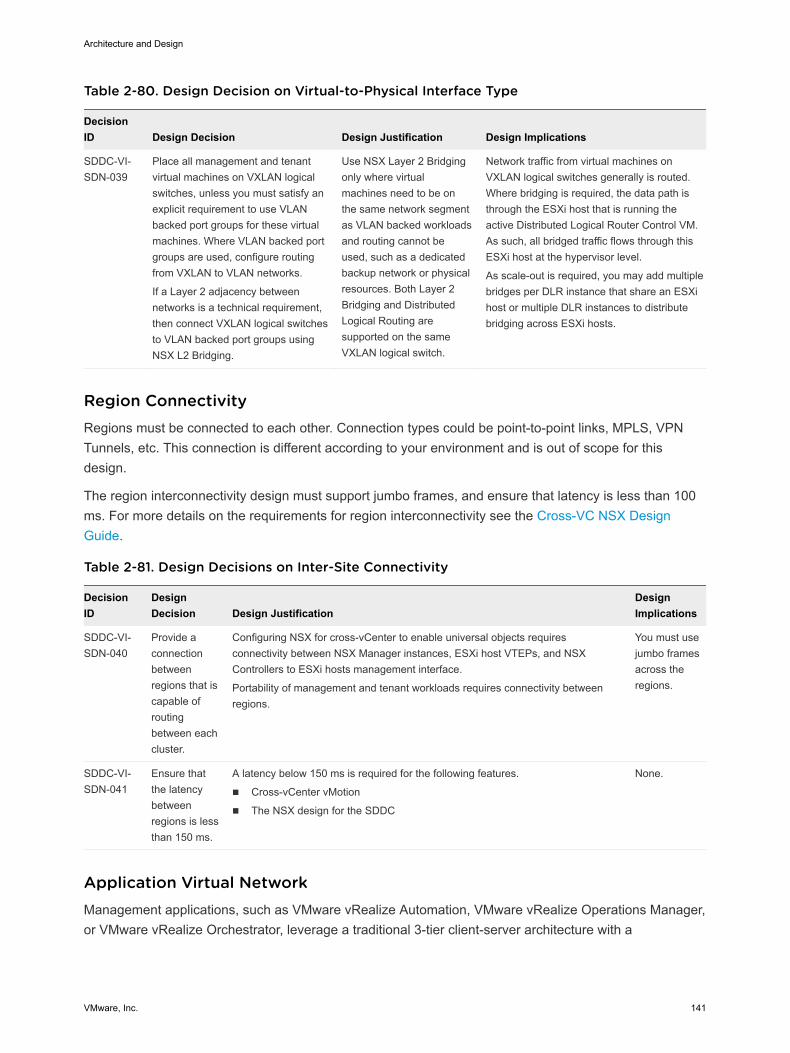
Table 2-80. Design Decision on Virtual-to-Physical Interface Type
DecisionID Design Decision Design Justification Design Implications
SDDC-VI-SDN-039
Place all management and tenantvirtual machines on VXLAN logicalswitches, unless you must satisfy anexplicit requirement to use VLANbacked port groups for these virtualmachines. Where VLAN backed portgroups are used, configure routingfrom VXLAN to VLAN networks.
If a Layer 2 adjacency betweennetworks is a technical requirement,then connect VXLAN logical switchesto VLAN backed port groups usingNSX L2 Bridging.
Use NSX Layer 2 Bridgingonly where virtualmachines need to be onthe same network segmentas VLAN backed workloadsand routing cannot beused, such as a dedicatedbackup network or physicalresources. Both Layer 2Bridging and DistributedLogical Routing aresupported on the sameVXLAN logical switch.
Network traffic from virtual machines onVXLAN logical switches generally is routed.Where bridging is required, the data path isthrough the ESXi host that is running theactive Distributed Logical Router Control VM.As such, all bridged traffic flows through thisESXi host at the hypervisor level.
As scale-out is required, you may add multiplebridges per DLR instance that share an ESXihost or multiple DLR instances to distributebridging across ESXi hosts.
Region Connectivity Regions must be connected to each other. Connection types could be point-to-point links, MPLS, VPNTunnels, etc. This connection is different according to your environment and is out of scope for thisdesign.
The region interconnectivity design must support jumbo frames, and ensure that latency is less than 100ms. For more details on the requirements for region interconnectivity see the Cross-VC NSX DesignGuide.
Table 2-81. Design Decisions on Inter-Site Connectivity
DecisionID
DesignDecision Design Justification
DesignImplications
SDDC-VI-SDN-040
Provide aconnectionbetweenregions that iscapable ofroutingbetween eachcluster.
Configuring NSX for cross-vCenter to enable universal objects requiresconnectivity between NSX Manager instances, ESXi host VTEPs, and NSXControllers to ESXi hosts management interface.
Portability of management and tenant workloads requires connectivity betweenregions.
You must usejumbo framesacross theregions.
SDDC-VI-SDN-041
Ensure thatthe latencybetweenregions is lessthan 150 ms.
A latency below 150 ms is required for the following features.
n Cross-vCenter vMotion
n The NSX design for the SDDC
None.
Application Virtual Network Management applications, such as VMware vRealize Automation, VMware vRealize Operations Manager,or VMware vRealize Orchestrator, leverage a traditional 3-tier client-server architecture with a
Architecture and Design
VMware, Inc. 141
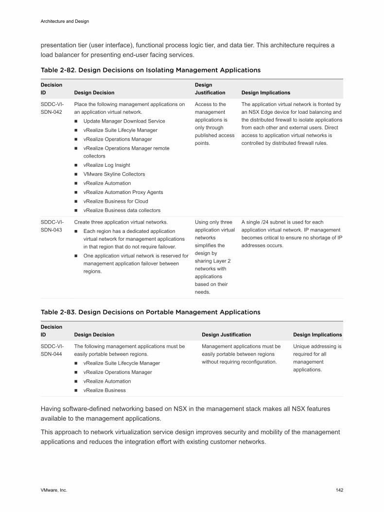
presentation tier (user interface), functional process logic tier, and data tier. This architecture requires aload balancer for presenting end-user facing services.
Table 2-82. Design Decisions on Isolating Management Applications
DecisionID Design Decision
DesignJustification Design Implications
SDDC-VI-SDN-042
Place the following management applications onan application virtual network.
n Update Manager Download Service
n vRealize Suite Lifecyle Manager
n vRealize Operations Manager
n vRealize Operations Manager remotecollectors
n vRealize Log Insight
n VMware Skyline Collectors
n vRealize Automation
n vRealize Automation Proxy Agents
n vRealize Business for Cloud
n vRealize Business data collectors
Access to themanagementapplications isonly throughpublished accesspoints.
The application virtual network is fronted byan NSX Edge device for load balancing andthe distributed firewall to isolate applicationsfrom each other and external users. Directaccess to application virtual networks iscontrolled by distributed firewall rules.
SDDC-VI-SDN-043
Create three application virtual networks.
n Each region has a dedicated applicationvirtual network for management applicationsin that region that do not require failover.
n One application virtual network is reserved formanagement application failover betweenregions.
Using only threeapplication virtualnetworkssimplifies thedesign bysharing Layer 2networks withapplicationsbased on theirneeds.
A single /24 subnet is used for eachapplication virtual network. IP managementbecomes critical to ensure no shortage of IPaddresses occurs.
Table 2-83. Design Decisions on Portable Management Applications
DecisionID Design Decision Design Justification Design Implications
SDDC-VI-SDN-044
The following management applications must beeasily portable between regions.
n vRealize Suite Lifecycle Manager
n vRealize Operations Manager
n vRealize Automation
n vRealize Business
Management applications must beeasily portable between regionswithout requiring reconfiguration.
Unique addressing isrequired for allmanagementapplications.
Having software-defined networking based on NSX in the management stack makes all NSX featuresavailable to the management applications.
This approach to network virtualization service design improves security and mobility of the managementapplications and reduces the integration effort with existing customer networks.
Architecture and Design
VMware, Inc. 142
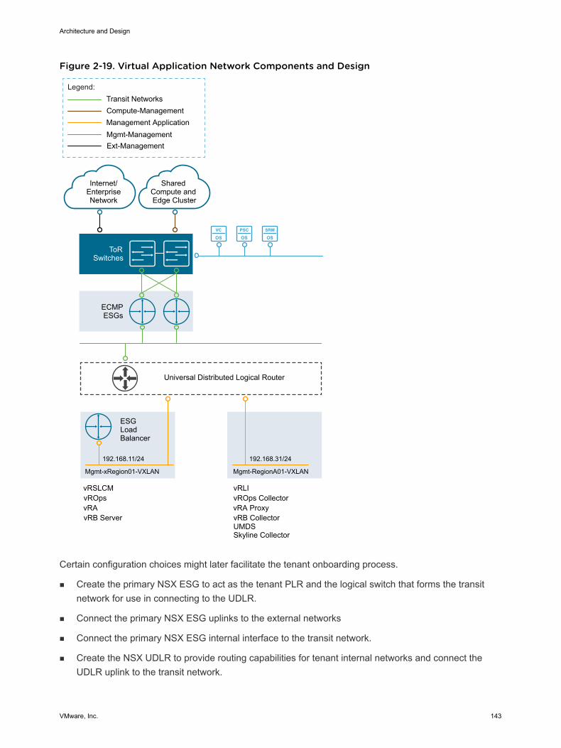
Figure 2-19. Virtual Application Network Components and Design
VC
OSPSC
OSSRM
OS
ECMPESGs
ToRSwitches
Internet/EnterpriseNetwork
Mgmt-Management
Compute-Management
Legend:
Shared Compute and Edge Cluster
192.168.11/24
Transit Networks
Management Application
vRAvROps
Universal Distributed Logical Router
ESGLoadBalancer
Mgmt-xRegion01-VXLAN
192.168.31/24
Mgmt-RegionA01-VXLAN
Ext-Management
vRB Server
vRLIvRSLCMvROps CollectorvRA Proxy
UMDSSkyline Collector
vRB Collector
Certain configuration choices might later facilitate the tenant onboarding process.
n Create the primary NSX ESG to act as the tenant PLR and the logical switch that forms the transitnetwork for use in connecting to the UDLR.
n Connect the primary NSX ESG uplinks to the external networks
n Connect the primary NSX ESG internal interface to the transit network.
n Create the NSX UDLR to provide routing capabilities for tenant internal networks and connect theUDLR uplink to the transit network.
Architecture and Design
VMware, Inc. 143
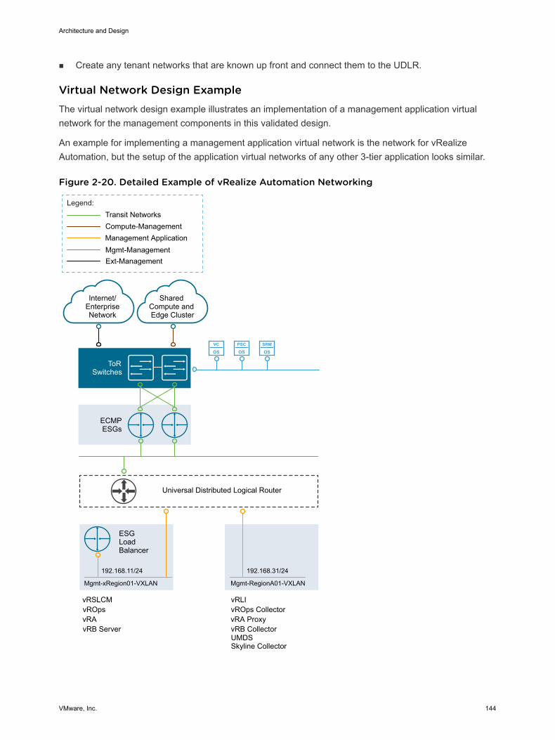
n Create any tenant networks that are known up front and connect them to the UDLR.
Virtual Network Design Example The virtual network design example illustrates an implementation of a management application virtualnetwork for the management components in this validated design.
An example for implementing a management application virtual network is the network for vRealizeAutomation, but the setup of the application virtual networks of any other 3-tier application looks similar.
Figure 2-20. Detailed Example of vRealize Automation Networking
VC
OSPSC
OSSRM
OS
ECMPESGs
ToRSwitches
Internet/EnterpriseNetwork
Mgmt-Management
Compute-Management
Legend:
Shared Compute and Edge Cluster
192.168.11/24
Transit Networks
Management Application
vRAvROps
Universal Distributed Logical Router
ESGLoadBalancer
Mgmt-xRegion01-VXLAN
192.168.31/24
Mgmt-RegionA01-VXLAN
Ext-Management
vRB Server
vRLIvRSLCMvROps CollectorvRA Proxy
UMDSSkyline Collector
vRB Collector
Architecture and Design
VMware, Inc. 144
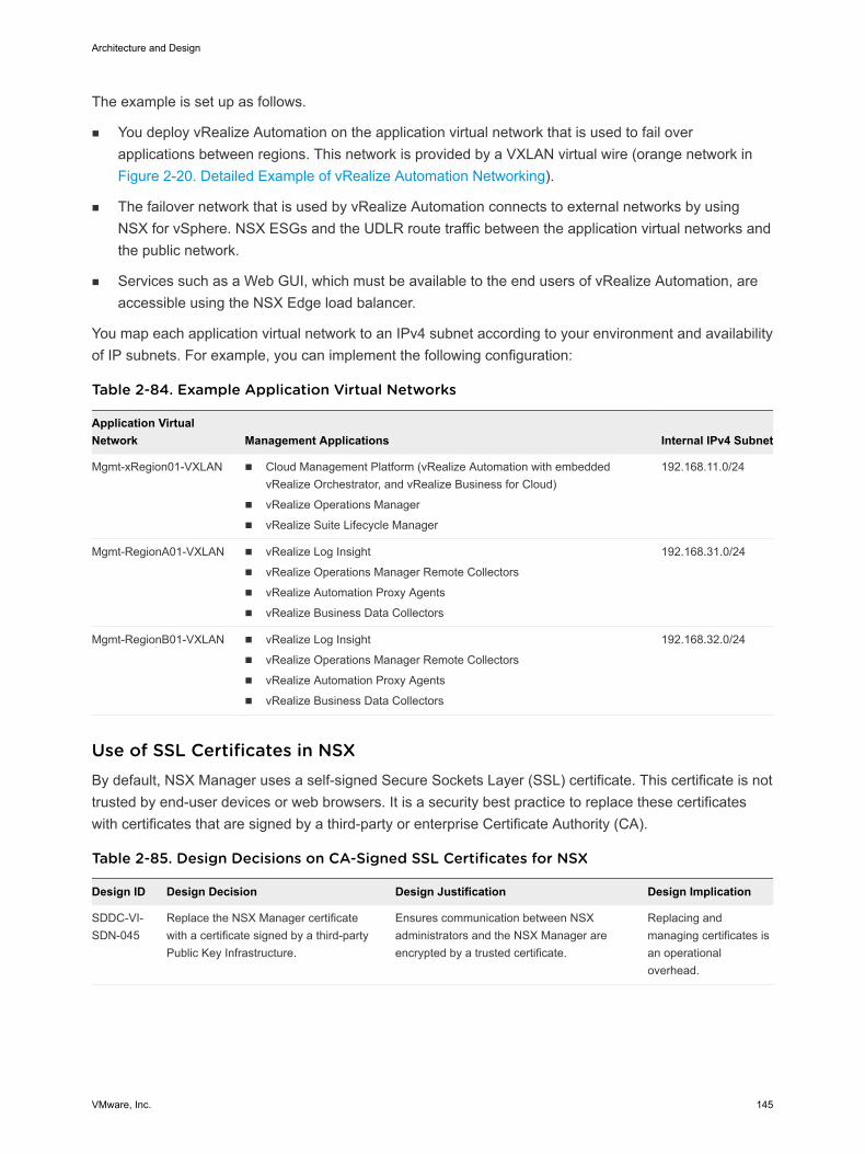
The example is set up as follows.
n You deploy vRealize Automation on the application virtual network that is used to fail overapplications between regions. This network is provided by a VXLAN virtual wire (orange network inFigure 2-20. Detailed Example of vRealize Automation Networking).
n The failover network that is used by vRealize Automation connects to external networks by usingNSX for vSphere. NSX ESGs and the UDLR route traffic between the application virtual networks andthe public network.
n Services such as a Web GUI, which must be available to the end users of vRealize Automation, areaccessible using the NSX Edge load balancer.
You map each application virtual network to an IPv4 subnet according to your environment and availabilityof IP subnets. For example, you can implement the following configuration:
Table 2-84. Example Application Virtual Networks
Application VirtualNetwork Management Applications Internal IPv4 Subnet
Mgmt-xRegion01-VXLAN n Cloud Management Platform (vRealize Automation with embeddedvRealize Orchestrator, and vRealize Business for Cloud)
n vRealize Operations Manager
n vRealize Suite Lifecycle Manager
192.168.11.0/24
Mgmt-RegionA01-VXLAN n vRealize Log Insight
n vRealize Operations Manager Remote Collectors
n vRealize Automation Proxy Agents
n vRealize Business Data Collectors
192.168.31.0/24
Mgmt-RegionB01-VXLAN n vRealize Log Insight
n vRealize Operations Manager Remote Collectors
n vRealize Automation Proxy Agents
n vRealize Business Data Collectors
192.168.32.0/24
Use of SSL Certificates in NSX By default, NSX Manager uses a self-signed Secure Sockets Layer (SSL) certificate. This certificate is nottrusted by end-user devices or web browsers. It is a security best practice to replace these certificateswith certificates that are signed by a third-party or enterprise Certificate Authority (CA).
Table 2-85. Design Decisions on CA-Signed SSL Certificates for NSX
Design ID Design Decision Design Justification Design Implication
SDDC-VI-SDN-045
Replace the NSX Manager certificatewith a certificate signed by a third-partyPublic Key Infrastructure.
Ensures communication between NSXadministrators and the NSX Manager areencrypted by a trusted certificate.
Replacing andmanaging certificates isan operationaloverhead.
Architecture and Design
VMware, Inc. 145
Shared Storage Design The shared storage design includes the design for vSAN and NFS storage.
Well-designed shared storage provides the basis for an SDDC and has the following benefits.
n Prevents unauthorized access to business data.
n Protects data from hardware and software failures.
n Protects data from malicious or accidental corruption.
Follow these guidelines when designing shared storage for your environment.
n Optimize the storage design to meet the diverse needs of applications, services, administrators, andusers.
n Strategically align business applications and the storage infrastructure to reduce costs, boostperformance, improve availability, provide security, and enhance functionality.
n Provide multiple tiers of storage to match application data access to application requirements.
n Design each tier of storage with different performance, capacity, and availability characteristics.Because not every application requires expensive, high-performance, highly available storage,designing different storage tiers reduces cost.
n Shared Storage Platform
You can choose between a traditional storage, VMware vSphere Virtual Volumes, and VMwarevSAN storage.
n Shared Storage Logical Design
The shared storage design selects the storage technology for each type of cluster.
n Datastore Cluster Design
A datastore cluster is a collection of datastores with shared resources and a shared managementinterface. Datastore clusters are to datastores what clusters are to ESXi hosts. After you create adatastore cluster, you can use vSphere Storage DRS to manage storage resources.
n vSAN Storage Design
VMware vSAN Storage design includes conceptual design, logical design, network design, clusterand disk group design, and policy design.
n NFS Storage Design
This NFS design does not give specific vendor or array guidance. Consult your storage vendor forthe configuration settings appropriate for your storage array.
Shared Storage Platform You can choose between a traditional storage, VMware vSphere Virtual Volumes, and VMware vSANstorage.
Architecture and Design
VMware, Inc. 146
Storage Types
Traditional Storage Fibre Channel, NFS, and iSCSI are mature and viable options to supportvirtual machine needs.
VMware vSAN Storage vSAN is a software-based distributed storage platform that combines thecompute and storage resources of VMware ESXi hosts. When you designand size a vSAN cluster, hardware choices are more limited than fortraditional storage.
VMware vSphere VirtualVolumes
This design does not use VMware vSphere Virtual Volumes because not allstorage arrays have the same vSphere Virtual Volume feature setsenabled.
Traditional Storage and vSAN Storage
Fibre Channel, NFS, and iSCSI are mature and viable options to support virtual machine needs.
Your decision to implement one technology or another can be based on performance and functionality,and on considerations like the following:
n The organization’s current in-house expertise and installation base
n The cost, including both capital and long-term operational expenses
n The organization’s current relationship with a storage vendor
vSAN is a software-based distributed storage platform that combines the compute and storage resourcesof ESXi hosts. It provides a simple storage management experience for the user. However, you mustcarefully consider supported hardware options when sizing and designing a vSAN cluster.
Storage Type Comparison
ESXi hosts support a variety of storage types. Each storage type supports different vSphere features.
Table 2-86. Network Shared Storage Supported by ESXi Hosts
Technology Protocols Transfers Interface
Fibre Channel FC/SCSI Block access of data/LUN Fibre Channel HBA
Fibre Channel over Ethernet FCoE/SCSI Block access of data/LUN Converged network adapter (hardware FCoE)
NIC with FCoE support (software FCoE)
iSCSI IP/SCSI Block access of data/LUN iSCSI HBA or iSCSI enabled NIC (hardware iSCSI)
Network Adapter (software iSCSI)
NAS IP/NFS File (no direct LUN access) Network adapter
vSAN IP Block access of data Network adapter
Architecture and Design
VMware, Inc. 147
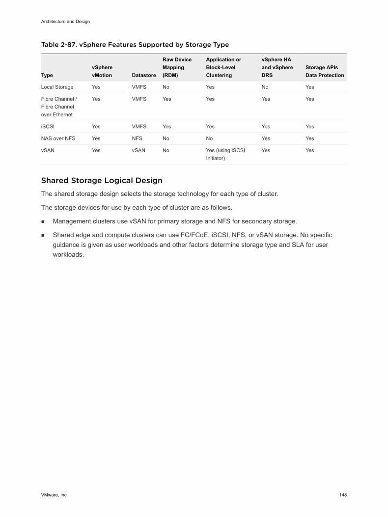
Table 2-87. vSphere Features Supported by Storage Type
TypevSpherevMotion Datastore
Raw DeviceMapping(RDM)
Application orBlock-LevelClustering
vSphere HAand vSphereDRS
Storage APIsData Protection
Local Storage Yes VMFS No Yes No Yes
Fibre Channel /Fibre Channelover Ethernet
Yes VMFS Yes Yes Yes Yes
iSCSI Yes VMFS Yes Yes Yes Yes
NAS over NFS Yes NFS No No Yes Yes
vSAN Yes vSAN No Yes (using iSCSIInitiator)
Yes Yes
Shared Storage Logical Design The shared storage design selects the storage technology for each type of cluster.
The storage devices for use by each type of cluster are as follows.
n Management clusters use vSAN for primary storage and NFS for secondary storage.
n Shared edge and compute clusters can use FC/FCoE, iSCSI, NFS, or vSAN storage. No specificguidance is given as user workloads and other factors determine storage type and SLA for userworkloads.
Architecture and Design
VMware, Inc. 148
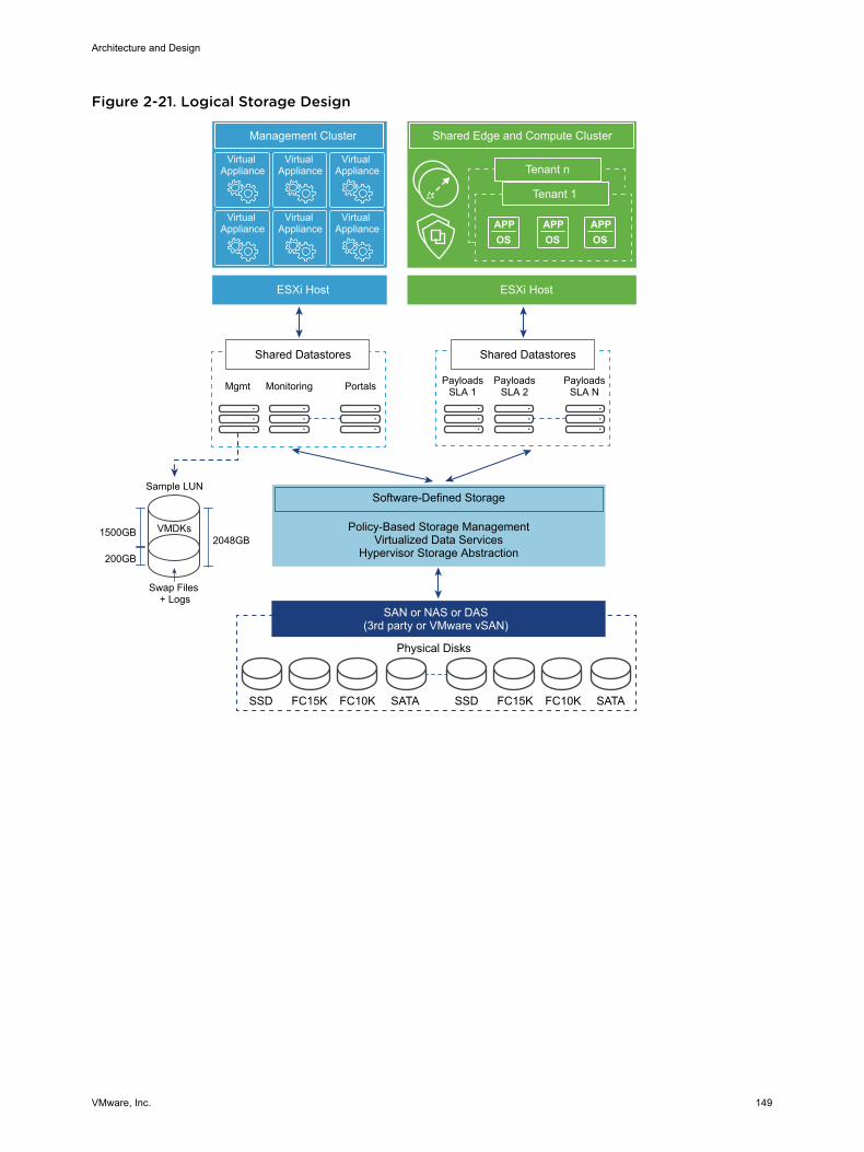
Figure 2-21. Logical Storage Design
Virtual Appliance
Virtual Appliance
Virtual Appliance
Virtual Appliance
Virtual Appliance
Virtual Appliance APP
OSAPPOS
APPOS
Tenant n
Management Cluster Shared Edge and Compute Cluster
Tenant 1
ESXi Host ESXi Host
Shared Datastores
Mgmt Monitoring Portals
Shared Datastores
PayloadsSLA 1
PayloadsSLA 2
PayloadsSLA N
Software-Defined Storage
Policy-Based Storage ManagementVirtualized Data Services
Hypervisor Storage Abstraction
SAN or NAS or DAS(3rd party or VMware vSAN)
Physical Disks
SSD FC15K FC10K SATA SSD FC15K FC10K SATA
VMDKs
Swap Files + Logs
1500GB
200GB
2048GB
Sample LUN
Architecture and Design
VMware, Inc. 149
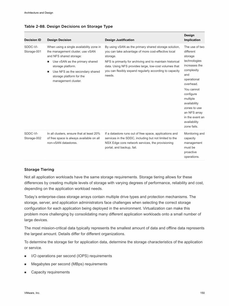
Table 2-88. Design Decisions on Storage Type
Decision ID Design Decision Design JustificationDesignImplication
SDDC-VI-Storage-001
When using a single availability zone inthe management cluster, use vSANand NFS shared storage:
n Use vSAN as the primary sharedstorage platform.
n Use NFS as the secondary sharedstorage platform for themanagement cluster.
By using vSAN as the primary shared storage solution,you can take advantage of more cost-effective localstorage.
NFS is primarily for archiving and to maintain historicaldata. Using NFS provides large, low-cost volumes thatyou can flexibly expand regularly according to capacityneeds.
The use of twodifferentstoragetechnologiesincreases thecomplexityandoperationaloverhead.
You cannotconfiguremultipleavailabilityzones to usean NFS arrayin the event anavailabilityzone fails.
SDDC-VI-Storage-002
In all clusters, ensure that at least 20%of free space is always available on allnon-vSAN datastores.
If a datastore runs out of free space, applications andservices in the SDDC, including but not limited to theNSX Edge core network services, the provisioningportal, and backup, fail.
Monitoring andcapacitymanagementmust beproactiveoperations.
Storage Tiering
Not all application workloads have the same storage requirements. Storage tiering allows for thesedifferences by creating multiple levels of storage with varying degrees of performance, reliability and cost,depending on the application workload needs.
Today’s enterprise-class storage arrays contain multiple drive types and protection mechanisms. Thestorage, server, and application administrators face challenges when selecting the correct storageconfiguration for each application being deployed in the environment. Virtualization can make thisproblem more challenging by consolidating many different application workloads onto a small number oflarge devices.
The most mission-critical data typically represents the smallest amount of data and offline data representsthe largest amount. Details differ for different organizations.
To determine the storage tier for application data, determine the storage characteristics of the applicationor service.
n I/O operations per second (IOPS) requirements
n Megabytes per second (MBps) requirements
n Capacity requirements
Architecture and Design
VMware, Inc. 150
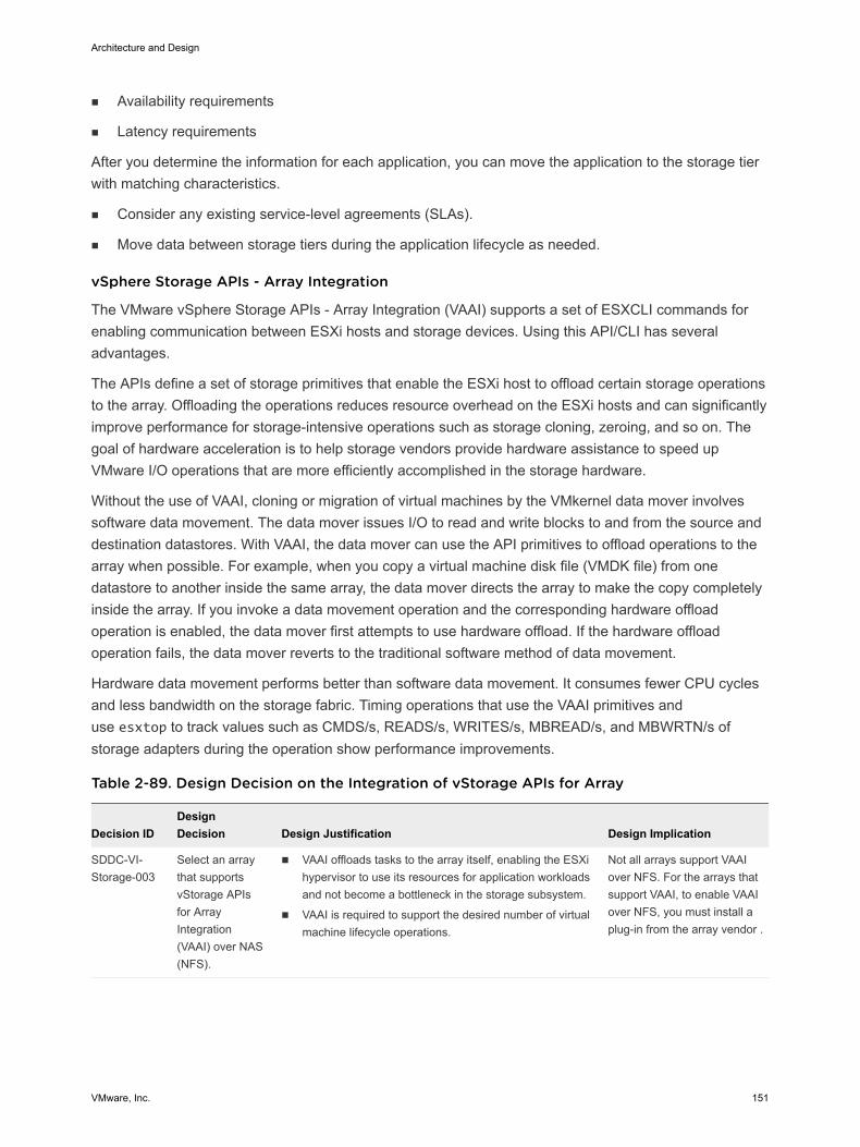
n Availability requirements
n Latency requirements
After you determine the information for each application, you can move the application to the storage tierwith matching characteristics.
n Consider any existing service-level agreements (SLAs).
n Move data between storage tiers during the application lifecycle as needed.
vSphere Storage APIs - Array Integration
The VMware vSphere Storage APIs - Array Integration (VAAI) supports a set of ESXCLI commands forenabling communication between ESXi hosts and storage devices. Using this API/CLI has severaladvantages.
The APIs define a set of storage primitives that enable the ESXi host to offload certain storage operationsto the array. Offloading the operations reduces resource overhead on the ESXi hosts and can significantlyimprove performance for storage-intensive operations such as storage cloning, zeroing, and so on. Thegoal of hardware acceleration is to help storage vendors provide hardware assistance to speed upVMware I/O operations that are more efficiently accomplished in the storage hardware.
Without the use of VAAI, cloning or migration of virtual machines by the VMkernel data mover involvessoftware data movement. The data mover issues I/O to read and write blocks to and from the source anddestination datastores. With VAAI, the data mover can use the API primitives to offload operations to thearray when possible. For example, when you copy a virtual machine disk file (VMDK file) from onedatastore to another inside the same array, the data mover directs the array to make the copy completelyinside the array. If you invoke a data movement operation and the corresponding hardware offloadoperation is enabled, the data mover first attempts to use hardware offload. If the hardware offloadoperation fails, the data mover reverts to the traditional software method of data movement.
Hardware data movement performs better than software data movement. It consumes fewer CPU cyclesand less bandwidth on the storage fabric. Timing operations that use the VAAI primitives anduse esxtop to track values such as CMDS/s, READS/s, WRITES/s, MBREAD/s, and MBWRTN/s ofstorage adapters during the operation show performance improvements.
Table 2-89. Design Decision on the Integration of vStorage APIs for Array
Decision IDDesignDecision Design Justification Design Implication
SDDC-VI-Storage-003
Select an arraythat supportsvStorage APIsfor ArrayIntegration(VAAI) over NAS(NFS).
n VAAI offloads tasks to the array itself, enabling the ESXihypervisor to use its resources for application workloadsand not become a bottleneck in the storage subsystem.
n VAAI is required to support the desired number of virtualmachine lifecycle operations.
Not all arrays support VAAIover NFS. For the arrays thatsupport VAAI, to enable VAAIover NFS, you must install aplug-in from the array vendor .
Architecture and Design
VMware, Inc. 151
Virtual Machine Storage Policies
You can create a storage policy for a virtual machine to specify which storage capabilities andcharacteristics are the best match for this virtual machine.
Note To specify the characteristics of virtual machines, use vSAN storage policies. You can define thepolicy at an individual disk level instead of at the volume level for vSAN.
You can identify the storage subsystem capabilities by using the VMware vSphere API for StorageAwareness (VASA) or by using a user-defined storage policy.
VMware vSphere APIfor Storage Awareness
With vSphere API for Storage Awareness, storage vendors can publish thecapabilities of their storage to VMware vCenter Server, which can displaythese capabilities in its user interface.
User-defined storagepolicy
You define the storage policy using the VMware Storage Policy SDK,VMware vSphere PowerCLI, or vSphere Client.
You can assign a storage policy to a virtual machine and periodically check for compliance so that thevirtual machine continues to run on storage with the correct performance and availability characteristics.vSphere Storage I/O Control Design VMware vSphere Storage I/O Control allows cluster-wide storage I/O prioritization, which results in betterworkload consolidation and helps reduce extra costs associated with over provisioning.
vSphere Storage I/O Control extends the constructs of shares and limits to storage I/O resources. Youcan control the amount of storage I/O that is allocated to virtual machines during periods of I/Ocongestion, so that more important virtual machines get preference over less important virtual machinesfor I/O resource allocation.
When vSphere Storage I/O Control is enabled on a datastore, the ESXi host monitors the device latencywhen communicating with that datastore. When device latency exceeds a threshold, the datastore isconsidered to be congested and each virtual machine that accesses that datastore is allocated I/Oresources in proportion to their shares. Shares are set on a per-virtual machine basis and can beadjusted.
vSphere Storage I/O Control has several requirements, limitations, and constraints.
n Datastores that are enabled with vSphere Storage I/O Control must be managed by a single vCenterServer system.
n Storage I/O Control is supported on Fibre Channel-connected, iSCSI-connected, and NFS-connectedstorage. RDM is not supported.
n Storage I/O Control does not support datastores with multiple extents.
n Before using vSphere Storage I/O Control on datastores that are backed by arrays with automatedstorage tiering capabilities, verify that the storage array has been certified as compatible with vSphereStorage I/O Control. See VMware Compatibility Guide.
Architecture and Design
VMware, Inc. 152
Table 2-90. Design Decisions on Storage I/O Control
Decision ID Design Decision Design Justification Design Implication
SDDC-VI-Storage-004
Enable Storage I/OControl with the defaultvalues on all non-vSANdatastores.
Storage I/O Control ensuresthat all virtual machines on adatastore receive an equalamount of I/O.
Virtual machines that use more I/O access thedatastore with priority. Other virtual machines canaccess the datastore only when an I/O contentionoccurs on the datastore.
Datastore Cluster Design A datastore cluster is a collection of datastores with shared resources and a shared managementinterface. Datastore clusters are to datastores what clusters are to ESXi hosts. After you create adatastore cluster, you can use vSphere Storage DRS to manage storage resources.
vSphere datastore clusters group similar datastores into a pool of storage resources. When vSphereStorage DRS is enabled on a datastore cluster, vSphere automates the process of initial virtual machinefile placement and balances storage resources across the cluster to avoid bottlenecks. vSphere StorageDRS considers datastore space usage and I/O load when making migration recommendations.
When you add a datastore to a datastore cluster, the datastore's resources become part of the datastorecluster's resources. The following resource management capabilities are also available for each datastorecluster.
Capability Description
Space utilization loadbalancing
You can set a threshold for space use. When space use on a datastore exceeds the threshold, vSphereStorage DRS generates recommendations or performs migrations with vSphere Storage vMotion tobalance space use across the datastore cluster.
I/O latency loadbalancing
You can configure the I/O latency threshold to avoid bottlenecks. When I/O latency on a datastore exceedsthe threshold, vSphere Storage DRS generates recommendations or performs vSphere Storage vMotionmigrations to help alleviate high I/O load.
Anti-affinity rules You can configure anti-affinity rules for virtual machine disks to ensure that the virtual disks of a virtualmachine are kept on different datastores. By default, all virtual disks for a virtual machine are placed on thesame datastore.
You can enable vSphere Storage I/O Control or vSphere Storage DRS for a datastore cluster. You canenable the two features separately, even though vSphere Storage I/O control is enabled by default whenyou enable vSphere Storage DRS.
vSphere Storage DRS Background Information
vSphere Storage DRS supports automating the management of datastores based on latency and storageutilization. When configuring vSphere Storage DRS, verify that all datastores use the same version ofVMFS and are on the same storage subsystem. Because vSphere Storage vMotion performs themigration of the virtual machines, confirm that all prerequisites are met.
vSphere Storage DRS provides a way of balancing usage and IOPS among datastores in a storagecluster:
n Initial placement of virtual machines is based on storage capacity.
Architecture and Design
VMware, Inc. 153
n vSphere Storage DRS uses vSphere Storage vMotion to migrate virtual machines based on storagecapacity.
n vSphere Storage DRS uses vSphere Storage vMotion to migrate virtual machines based on I/Olatency.
n You can configure vSphere Storage DRS to run in either manual mode or in fully automated mode.
vSphere Storage I/O Control and vSphere Storage DRS manage latency differently.
n vSphere Storage I/O Control distributes the resources based on virtual disk share value after alatency threshold is reached.
n vSphere Storage DRS measures latency over a period of time. If the latency threshold of vSphereStorage DRS is met in that time frame, vSphere Storage DRS migrates virtual machines to balancelatency across the datastores that are part of the cluster.
When making a vSphere Storage design decision, consider these points:
n Use vSphere Storage DRS where possible.
n vSphere Storage DRS provides a way of balancing usage and IOPS among datastores in a storagecluster:
n Initial placement of virtual machines is based on storage capacity.
n vSphere Storage vMotion is used to migrate virtual machines based on storage capacity.
n vSphere Storage vMotion is used to migrate virtual machines based on I/O latency.
n vSphere Storage DRS can be configured in either manual or fully automated modes
vSAN Storage Design VMware vSAN Storage design includes conceptual design, logical design, network design, cluster anddisk group design, and policy design.
n vSAN Conceptual Design and Logical Design
This vSAN design is limited to the management cluster. The design uses the default storage policyto achieve redundancy and performance within the cluster.
n vSAN Network Design
When performing network configuration, you have to consider the overall traffic and decide how toisolate vSAN traffic.
n vSAN Cluster and Disk Group Design
When considering the cluster and disk group design, you have to decide on the vSAN datastoresize, number of ESXi hosts per cluster, number of disk groups per ESXi host, and the vSAN policy.
n vSAN Policy Design
After you enable and configure VMware vSAN, you can create storage policies that define the virtualmachine storage characteristics. Storage characteristics specify different levels of service fordifferent virtual machines.
Architecture and Design
VMware, Inc. 154
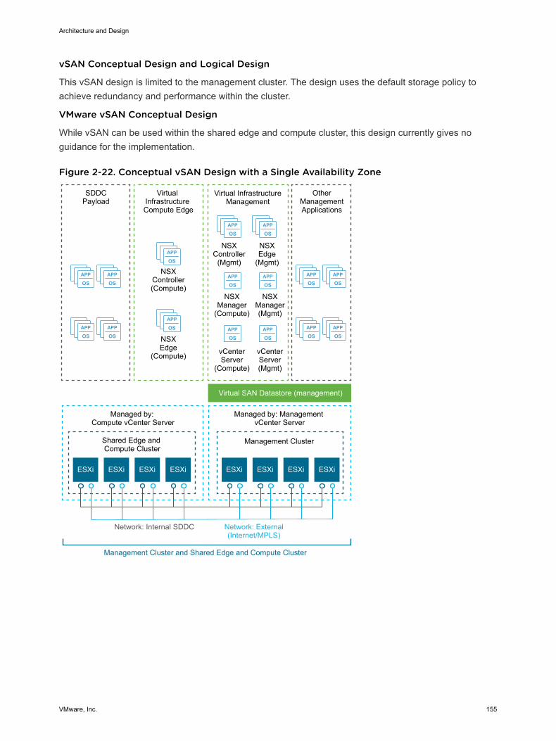
vSAN Conceptual Design and Logical Design
This vSAN design is limited to the management cluster. The design uses the default storage policy toachieve redundancy and performance within the cluster.
VMware vSAN Conceptual Design
While vSAN can be used within the shared edge and compute cluster, this design currently gives noguidance for the implementation.
Figure 2-22. Conceptual vSAN Design with a Single Availability Zone
APP
OSAPP
OS
APP
OSAPP
OS
APP
OSAPP
OS
APP
OSAPP
OS
APP
OS
APP
OS
APP
OSAPP
OS
APP
OSAPP
OS
APP
OSAPP
OS
ESXi ESXi
Virtual InfrastructureManagement
NSXController
(Mgmt)
OtherManagementApplications
NSXEdge
(Mgmt)
NSXManager(Mgmt)
NSXManager
(Compute)
NSXEdge
(Compute)
NSXController(Compute)
ESXi ESXi ESXi ESXi ESXi ESXi
SDDCPayload
Virtual Infrastructure Compute Edge
Virtual SAN Datastore (management)
Shared Edge and Compute Cluster
Management Cluster
Managed by: Compute vCenter Server
Managed by: Management vCenter Server
Network: External(Internet/MPLS)
Network: Internal SDDC
Management Cluster and Shared Edge and Compute Cluster
vCenterServer(Mgmt)
vCenterServer
(Compute)
Architecture and Design
VMware, Inc. 155
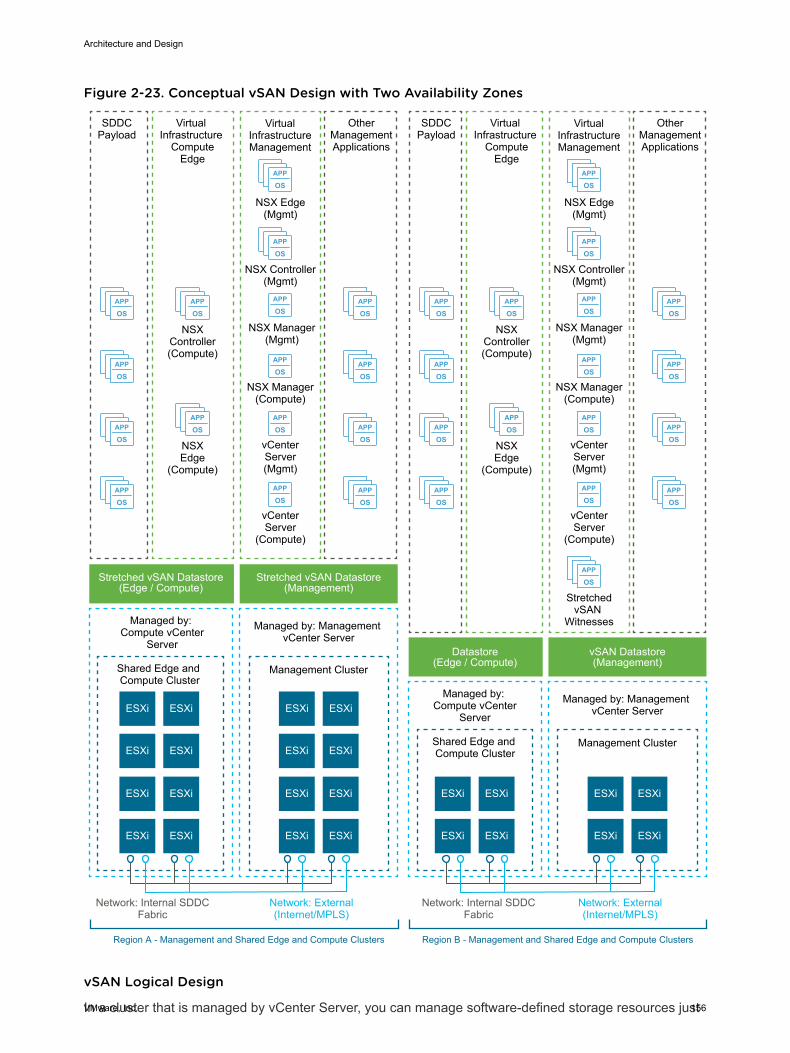
Figure 2-23. Conceptual vSAN Design with Two Availability Zones
APP
OS
APP
OS
APP
OS
APP
OSAPP
OS
APP
OS
APP
OS
APP
OS
ESXi
APP
OS
APP
OS
APP
OS
APP
OS
APP
OS
APP
OS
APP
OS
APP
OS
APP
OS
APP
OS
APP
OS
APP
OSAPP
OS
APP
OS
APP
OS
APP
OSAPP
OS
APP
OS
APP
OS
APP
OS
APP
OS
APP
OS
APP
OS
APP
OS
APP
OS
VirtualInfrastructureManagement
NSX Controller(Mgmt)
OtherManagementApplications
NSX Edge(Mgmt)
NSX Manager(Mgmt)
NSX Manager(Compute)
NSXEdge
(Compute)
NSXController(Compute)
ESXi
ESXi ESXi
SDDCPayload
Virtual Infrastructure
ComputeEdge
Stretched vSAN Datastore(Edge / Compute)
Stretched vSAN Datastore(Management)
Shared Edge and Compute Cluster
Management Cluster
Managed by: Compute vCenter
Server
Managed by: Management vCenter Server
Network: External(Internet/MPLS)
Network: Internal SDDCFabric
Region A - Management and Shared Edge and Compute Clusters
vCenterServer(Mgmt)
vCenterServer
(Compute)
ESXiESXi
ESXi ESXi
ESXiESXi
ESXi ESXi
ESXiESXi
ESXi ESXi
ESXi
VirtualInfrastructureManagement
NSX Controller(Mgmt)
OtherManagementApplications
NSX Edge(Mgmt)
NSX Manager(Mgmt)
NSX Manager(Compute)
NSXEdge
(Compute)
NSXController(Compute)
ESXi
ESXi ESXi
SDDCPayload
Virtual Infrastructure
ComputeEdge
Datastore(Edge / Compute)
vSAN Datastore(Management)
Shared Edge and Compute Cluster
Management Cluster
Managed by: Compute vCenter
Server
Managed by: Management vCenter Server
Network: External(Internet/MPLS)
Network: Internal SDDCFabric
Region B - Management and Shared Edge and Compute Clusters
vCenterServer(Mgmt)
vCenterServer
(Compute)
ESXiESXi
ESXi ESXi
StretchedvSAN
Witnesses
vSAN Logical Design
In a cluster that is managed by vCenter Server, you can manage software-defined storage resources just
Architecture and Design
VMware, Inc. 156
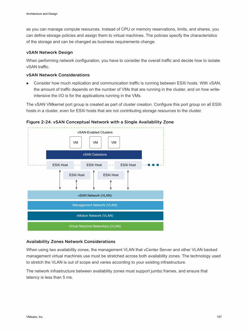
as you can manage compute resources. Instead of CPU or memory reservations, limits, and shares, youcan define storage policies and assign them to virtual machines. The policies specify the characteristicsof the storage and can be changed as business requirements change.
vSAN Network Design
When performing network configuration, you have to consider the overall traffic and decide how to isolatevSAN traffic.
vSAN Network Considerations
n Consider how much replication and communication traffic is running between ESXi hosts. With vSAN,the amount of traffic depends on the number of VMs that are running in the cluster, and on how write-intensive the I/O is for the applications running in the VMs.
The vSAN VMkernel port group is created as part of cluster creation. Configure this port group on all ESXihosts in a cluster, even for ESXi hosts that are not contributing storage resources to the cluster.
Figure 2-24. vSAN Conceptual Network with a Single Availability Zone
VM VM VM
ESXi Host ESXi Host ESXi Host
ESXi Host ESXi Host
vSAN Datastore
vSAN-Enabled Clusters
vSAN Network (VLAN)
Management Network (VLAN)
vMotion Network (VLAN)
Virtual Machine Network(s) (VLAN)
Availability Zones Network Considerations
When using two availability zones, the management VLAN that vCenter Server and other VLAN backedmanagement virtual machines use must be stretched across both availability zones. The technology usedto stretch the VLAN is out of scope and varies according to your existing infrastructure.
The network infrastructure between availability zones must support jumbo frames, and ensure thatlatency is less than 5 ms.
Architecture and Design
VMware, Inc. 157
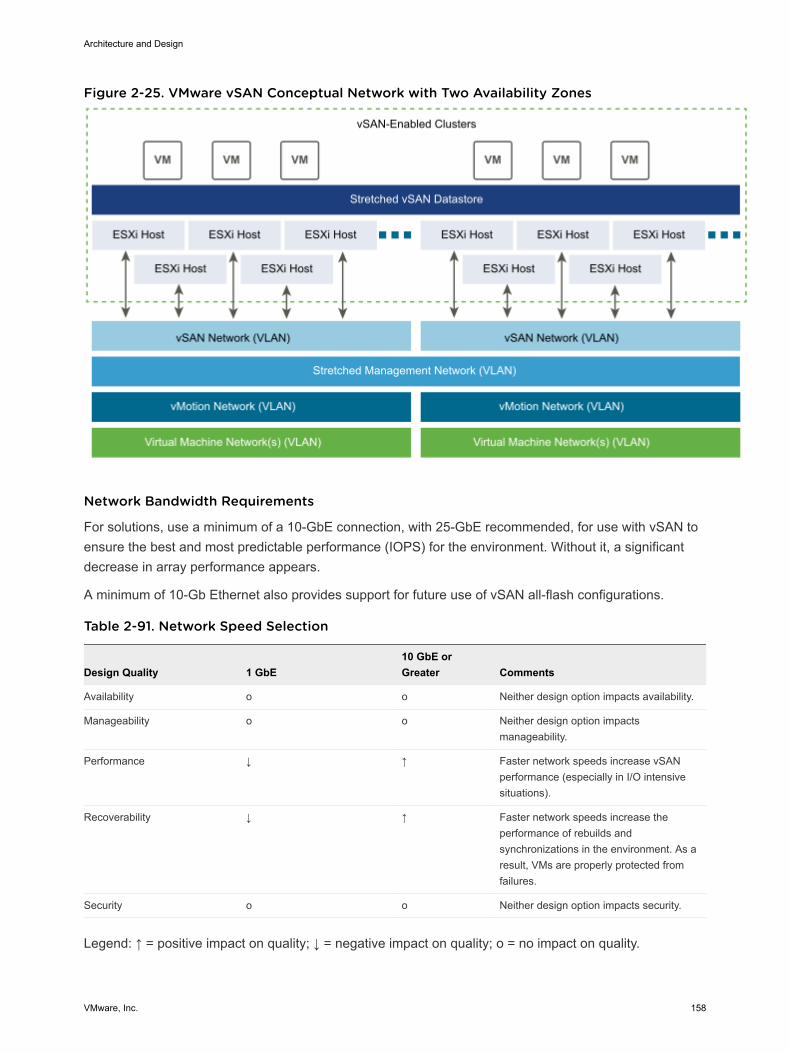
Figure 2-25. VMware vSAN Conceptual Network with Two Availability Zones
Network Bandwidth Requirements
For solutions, use a minimum of a 10-GbE connection, with 25-GbE recommended, for use with vSAN toensure the best and most predictable performance (IOPS) for the environment. Without it, a significantdecrease in array performance appears.
A minimum of 10-Gb Ethernet also provides support for future use of vSAN all-flash configurations.
Table 2-91. Network Speed Selection
Design Quality 1 GbE10 GbE orGreater Comments
Availability o o Neither design option impacts availability.
Manageability o o Neither design option impactsmanageability.
Performance ↓ ↑ Faster network speeds increase vSANperformance (especially in I/O intensivesituations).
Recoverability ↓ ↑ Faster network speeds increase theperformance of rebuilds andsynchronizations in the environment. As aresult, VMs are properly protected fromfailures.
Security o o Neither design option impacts security.
Legend: ↑ = positive impact on quality; ↓ = negative impact on quality; o = no impact on quality.
Architecture and Design
VMware, Inc. 158
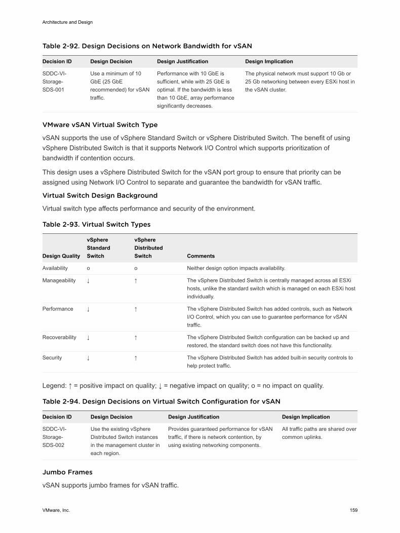
Table 2-92. Design Decisions on Network Bandwidth for vSAN
Decision ID Design Decision Design Justification Design Implication
SDDC-VI-Storage-SDS-001
Use a minimum of 10GbE (25 GbErecommended) for vSANtraffic.
Performance with 10 GbE issufficient, while with 25 GbE isoptimal. If the bandwidth is lessthan 10 GbE, array performancesignificantly decreases.
The physical network must support 10 Gb or25 Gb networking between every ESXi host inthe vSAN cluster.
VMware vSAN Virtual Switch Type
vSAN supports the use of vSphere Standard Switch or vSphere Distributed Switch. The benefit of usingvSphere Distributed Switch is that it supports Network I/O Control which supports prioritization ofbandwidth if contention occurs.
This design uses a vSphere Distributed Switch for the vSAN port group to ensure that priority can beassigned using Network I/O Control to separate and guarantee the bandwidth for vSAN traffic.
Virtual Switch Design Background
Virtual switch type affects performance and security of the environment.
Table 2-93. Virtual Switch Types
Design Quality
vSphereStandardSwitch
vSphereDistributedSwitch Comments
Availability o o Neither design option impacts availability.
Manageability ↓ ↑ The vSphere Distributed Switch is centrally managed across all ESXihosts, unlike the standard switch which is managed on each ESXi hostindividually.
Performance ↓ ↑ The vSphere Distributed Switch has added controls, such as NetworkI/O Control, which you can use to guarantee performance for vSANtraffic.
Recoverability ↓ ↑ The vSphere Distributed Switch configuration can be backed up andrestored, the standard switch does not have this functionality.
Security ↓ ↑ The vSphere Distributed Switch has added built-in security controls tohelp protect traffic.
Legend: ↑ = positive impact on quality; ↓ = negative impact on quality; o = no impact on quality.
Table 2-94. Design Decisions on Virtual Switch Configuration for vSAN
Decision ID Design Decision Design Justification Design Implication
SDDC-VI-Storage-SDS-002
Use the existing vSphereDistributed Switch instancesin the management cluster ineach region.
Provides guaranteed performance for vSANtraffic, if there is network contention, byusing existing networking components.
All traffic paths are shared overcommon uplinks.
Jumbo Frames
vSAN supports jumbo frames for vSAN traffic.
Architecture and Design
VMware, Inc. 159
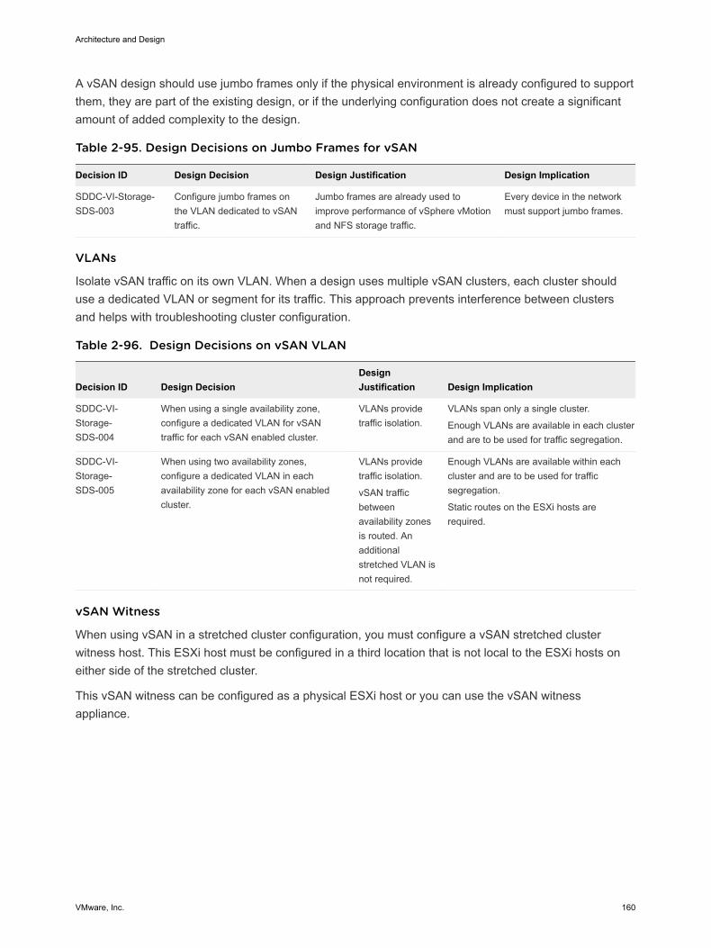
A vSAN design should use jumbo frames only if the physical environment is already configured to supportthem, they are part of the existing design, or if the underlying configuration does not create a significantamount of added complexity to the design.
Table 2-95. Design Decisions on Jumbo Frames for vSAN
Decision ID Design Decision Design Justification Design Implication
SDDC-VI-Storage-SDS-003
Configure jumbo frames onthe VLAN dedicated to vSANtraffic.
Jumbo frames are already used toimprove performance of vSphere vMotionand NFS storage traffic.
Every device in the networkmust support jumbo frames.
VLANs
Isolate vSAN traffic on its own VLAN. When a design uses multiple vSAN clusters, each cluster shoulduse a dedicated VLAN or segment for its traffic. This approach prevents interference between clustersand helps with troubleshooting cluster configuration.
Table 2-96. Design Decisions on vSAN VLAN
Decision ID Design DecisionDesignJustification Design Implication
SDDC-VI-Storage-SDS-004
When using a single availability zone,configure a dedicated VLAN for vSANtraffic for each vSAN enabled cluster.
VLANs providetraffic isolation.
VLANs span only a single cluster.
Enough VLANs are available in each clusterand are to be used for traffic segregation.
SDDC-VI-Storage-SDS-005
When using two availability zones,configure a dedicated VLAN in eachavailability zone for each vSAN enabledcluster.
VLANs providetraffic isolation.
vSAN trafficbetweenavailability zonesis routed. Anadditionalstretched VLAN isnot required.
Enough VLANs are available within eachcluster and are to be used for trafficsegregation.
Static routes on the ESXi hosts arerequired.
vSAN Witness
When using vSAN in a stretched cluster configuration, you must configure a vSAN stretched clusterwitness host. This ESXi host must be configured in a third location that is not local to the ESXi hosts oneither side of the stretched cluster.
This vSAN witness can be configured as a physical ESXi host or you can use the vSAN witnessappliance.
Architecture and Design
VMware, Inc. 160
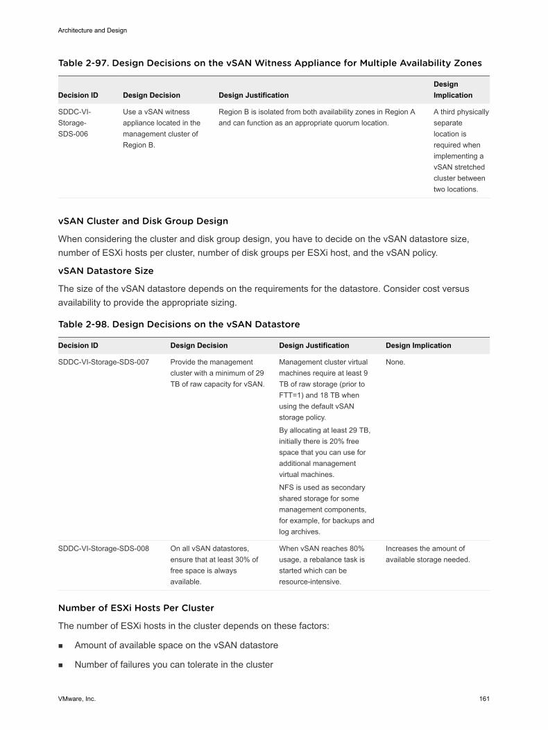
Table 2-97. Design Decisions on the vSAN Witness Appliance for Multiple Availability Zones
Decision ID Design Decision Design JustificationDesignImplication
SDDC-VI-Storage-SDS-006
Use a vSAN witnessappliance located in themanagement cluster ofRegion B.
Region B is isolated from both availability zones in Region Aand can function as an appropriate quorum location.
A third physicallyseparatelocation isrequired whenimplementing avSAN stretchedcluster betweentwo locations.
vSAN Cluster and Disk Group Design
When considering the cluster and disk group design, you have to decide on the vSAN datastore size,number of ESXi hosts per cluster, number of disk groups per ESXi host, and the vSAN policy.
vSAN Datastore Size
The size of the vSAN datastore depends on the requirements for the datastore. Consider cost versusavailability to provide the appropriate sizing.
Table 2-98. Design Decisions on the vSAN Datastore
Decision ID Design Decision Design Justification Design Implication
SDDC-VI-Storage-SDS-007 Provide the managementcluster with a minimum of 29TB of raw capacity for vSAN.
Management cluster virtualmachines require at least 9TB of raw storage (prior toFTT=1) and 18 TB whenusing the default vSANstorage policy.
By allocating at least 29 TB,initially there is 20% freespace that you can use foradditional managementvirtual machines.
NFS is used as secondaryshared storage for somemanagement components,for example, for backups andlog archives.
None.
SDDC-VI-Storage-SDS-008 On all vSAN datastores,ensure that at least 30% offree space is alwaysavailable.
When vSAN reaches 80%usage, a rebalance task isstarted which can beresource-intensive.
Increases the amount ofavailable storage needed.
Number of ESXi Hosts Per Cluster
The number of ESXi hosts in the cluster depends on these factors:
n Amount of available space on the vSAN datastore
n Number of failures you can tolerate in the cluster
Architecture and Design
VMware, Inc. 161
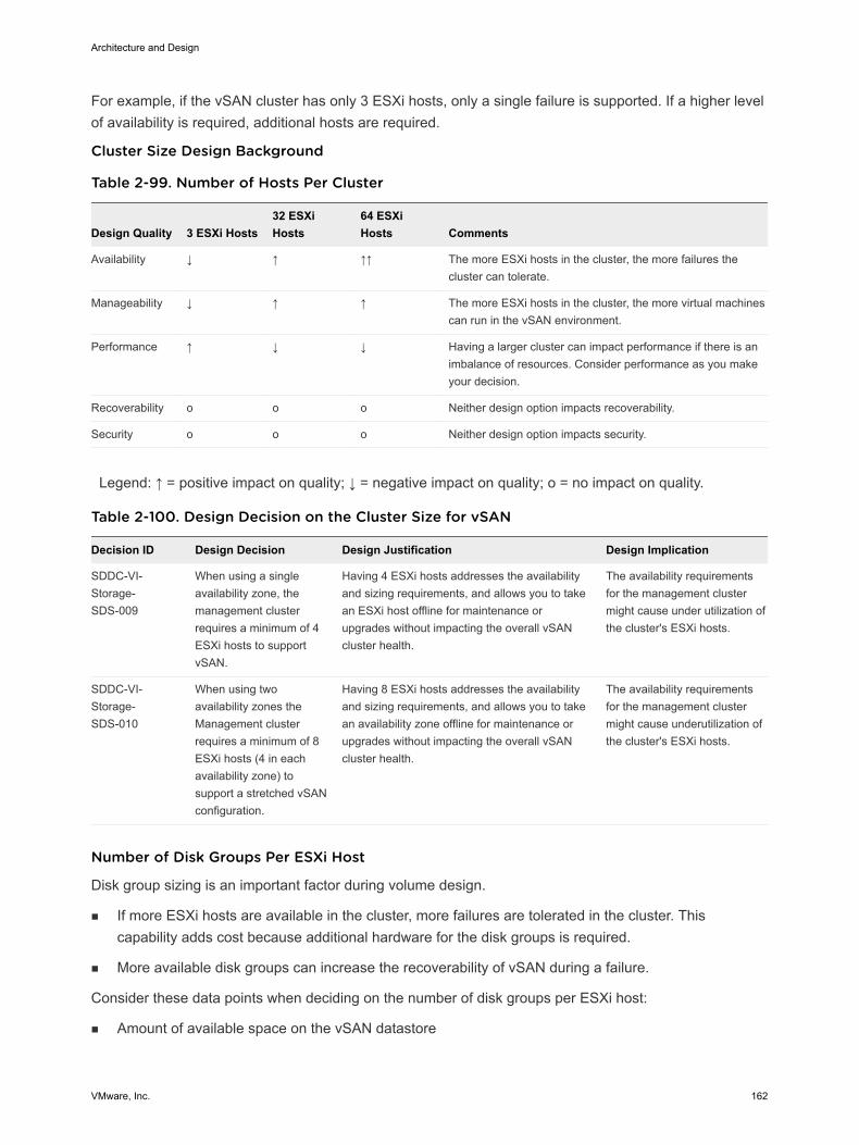
For example, if the vSAN cluster has only 3 ESXi hosts, only a single failure is supported. If a higher levelof availability is required, additional hosts are required.
Cluster Size Design Background
Table 2-99. Number of Hosts Per Cluster
Design Quality 3 ESXi Hosts32 ESXiHosts
64 ESXiHosts Comments
Availability ↓ ↑ ↑↑ The more ESXi hosts in the cluster, the more failures thecluster can tolerate.
Manageability ↓ ↑ ↑ The more ESXi hosts in the cluster, the more virtual machinescan run in the vSAN environment.
Performance ↑ ↓ ↓ Having a larger cluster can impact performance if there is animbalance of resources. Consider performance as you makeyour decision.
Recoverability o o o Neither design option impacts recoverability.
Security o o o Neither design option impacts security.
Legend: ↑ = positive impact on quality; ↓ = negative impact on quality; o = no impact on quality.
Table 2-100. Design Decision on the Cluster Size for vSAN
Decision ID Design Decision Design Justification Design Implication
SDDC-VI-Storage-SDS-009
When using a singleavailability zone, themanagement clusterrequires a minimum of 4ESXi hosts to supportvSAN.
Having 4 ESXi hosts addresses the availabilityand sizing requirements, and allows you to takean ESXi host offline for maintenance orupgrades without impacting the overall vSANcluster health.
The availability requirementsfor the management clustermight cause under utilization ofthe cluster's ESXi hosts.
SDDC-VI-Storage-SDS-010
When using twoavailability zones theManagement clusterrequires a minimum of 8ESXi hosts (4 in eachavailability zone) tosupport a stretched vSANconfiguration.
Having 8 ESXi hosts addresses the availabilityand sizing requirements, and allows you to takean availability zone offline for maintenance orupgrades without impacting the overall vSANcluster health.
The availability requirementsfor the management clustermight cause underutilization ofthe cluster's ESXi hosts.
Number of Disk Groups Per ESXi Host
Disk group sizing is an important factor during volume design.
n If more ESXi hosts are available in the cluster, more failures are tolerated in the cluster. Thiscapability adds cost because additional hardware for the disk groups is required.
n More available disk groups can increase the recoverability of vSAN during a failure.
Consider these data points when deciding on the number of disk groups per ESXi host:
n Amount of available space on the vSAN datastore
Architecture and Design
VMware, Inc. 162
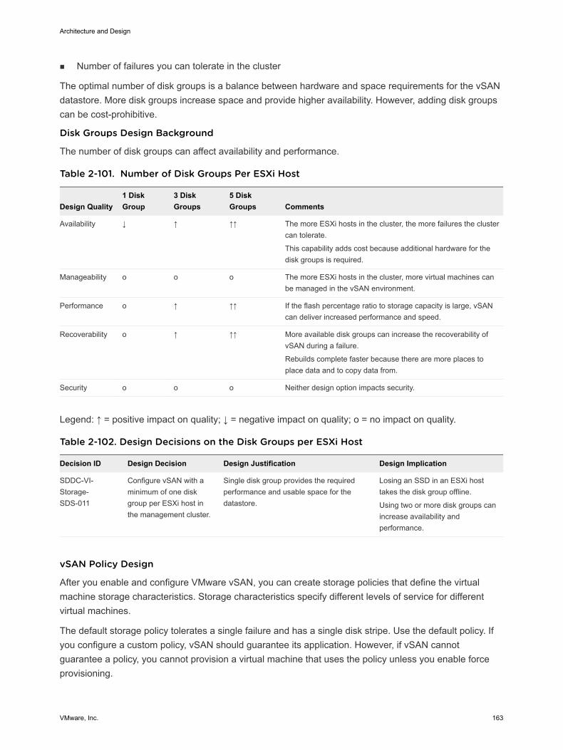
n Number of failures you can tolerate in the cluster
The optimal number of disk groups is a balance between hardware and space requirements for the vSANdatastore. More disk groups increase space and provide higher availability. However, adding disk groupscan be cost-prohibitive.
Disk Groups Design Background
The number of disk groups can affect availability and performance.
Table 2-101. Number of Disk Groups Per ESXi Host
Design Quality1 DiskGroup
3 DiskGroups
5 DiskGroups Comments
Availability ↓ ↑ ↑↑ The more ESXi hosts in the cluster, the more failures the clustercan tolerate.
This capability adds cost because additional hardware for thedisk groups is required.
Manageability o o o The more ESXi hosts in the cluster, more virtual machines canbe managed in the vSAN environment.
Performance o ↑ ↑↑ If the flash percentage ratio to storage capacity is large, vSANcan deliver increased performance and speed.
Recoverability o ↑ ↑↑ More available disk groups can increase the recoverability ofvSAN during a failure.
Rebuilds complete faster because there are more places toplace data and to copy data from.
Security o o o Neither design option impacts security.
Legend: ↑ = positive impact on quality; ↓ = negative impact on quality; o = no impact on quality.
Table 2-102. Design Decisions on the Disk Groups per ESXi Host
Decision ID Design Decision Design Justification Design Implication
SDDC-VI-Storage-SDS-011
Configure vSAN with aminimum of one diskgroup per ESXi host inthe management cluster.
Single disk group provides the requiredperformance and usable space for thedatastore.
Losing an SSD in an ESXi hosttakes the disk group offline.
Using two or more disk groups canincrease availability andperformance.
vSAN Policy Design
After you enable and configure VMware vSAN, you can create storage policies that define the virtualmachine storage characteristics. Storage characteristics specify different levels of service for differentvirtual machines.
The default storage policy tolerates a single failure and has a single disk stripe. Use the default policy. Ifyou configure a custom policy, vSAN should guarantee its application. However, if vSAN cannotguarantee a policy, you cannot provision a virtual machine that uses the policy unless you enable forceprovisioning.
Architecture and Design
VMware, Inc. 163
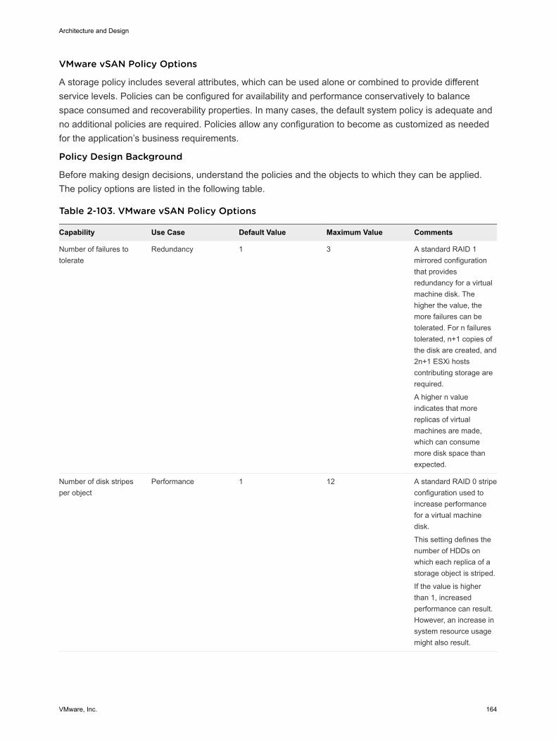
VMware vSAN Policy Options
A storage policy includes several attributes, which can be used alone or combined to provide differentservice levels. Policies can be configured for availability and performance conservatively to balancespace consumed and recoverability properties. In many cases, the default system policy is adequate andno additional policies are required. Policies allow any configuration to become as customized as neededfor the application’s business requirements.
Policy Design Background
Before making design decisions, understand the policies and the objects to which they can be applied.The policy options are listed in the following table.
Table 2-103. VMware vSAN Policy Options
Capability Use Case Default Value Maximum Value Comments
Number of failures totolerate
Redundancy 1 3 A standard RAID 1mirrored configurationthat providesredundancy for a virtualmachine disk. Thehigher the value, themore failures can betolerated. For n failurestolerated, n+1 copies ofthe disk are created, and2n+1 ESXi hostscontributing storage arerequired.
A higher n valueindicates that morereplicas of virtualmachines are made,which can consumemore disk space thanexpected.
Number of disk stripesper object
Performance 1 12 A standard RAID 0 stripeconfiguration used toincrease performancefor a virtual machinedisk.
This setting defines thenumber of HDDs onwhich each replica of astorage object is striped.
If the value is higherthan 1, increasedperformance can result.However, an increase insystem resource usagemight also result.
Architecture and Design
VMware, Inc. 164
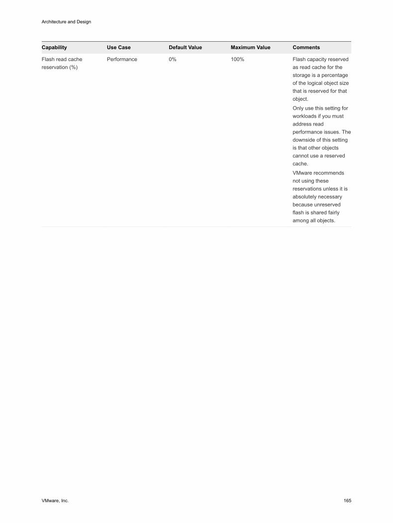
Capability Use Case Default Value Maximum Value Comments
Flash read cachereservation (%)
Performance 0% 100% Flash capacity reservedas read cache for thestorage is a percentageof the logical object sizethat is reserved for thatobject.
Only use this setting forworkloads if you mustaddress readperformance issues. Thedownside of this settingis that other objectscannot use a reservedcache.
VMware recommendsnot using thesereservations unless it isabsolutely necessarybecause unreservedflash is shared fairlyamong all objects.
Architecture and Design
VMware, Inc. 165
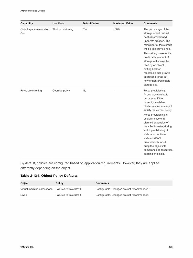
Capability Use Case Default Value Maximum Value Comments
Object space reservation(%)
Thick provisioning 0% 100% The percentage of thestorage object that willbe thick provisionedupon VM creation. Theremainder of the storagewill be thin provisioned.
This setting is useful if apredictable amount ofstorage will always befilled by an object,cutting back onrepeatable disk growthoperations for all butnew or non-predictablestorage use.
Force provisioning Override policy No - Force provisioningforces provisioning tooccur even if thecurrently availablecluster resources cannotsatisfy the current policy.
Force provisioning isuseful in case of aplanned expansion ofthe vSAN cluster, duringwhich provisioning ofVMs must continue.VMware vSANautomatically tries tobring the object intocompliance as resourcesbecome available.
By default, policies are configured based on application requirements. However, they are applieddifferently depending on the object.
Table 2-104. Object Policy Defaults
Object Policy Comments
Virtual machine namespace Failures-to-Tolerate: 1 Configurable. Changes are not recommended.
Swap Failures-to-Tolerate: 1 Configurable. Changes are not recommended.
Architecture and Design
VMware, Inc. 166
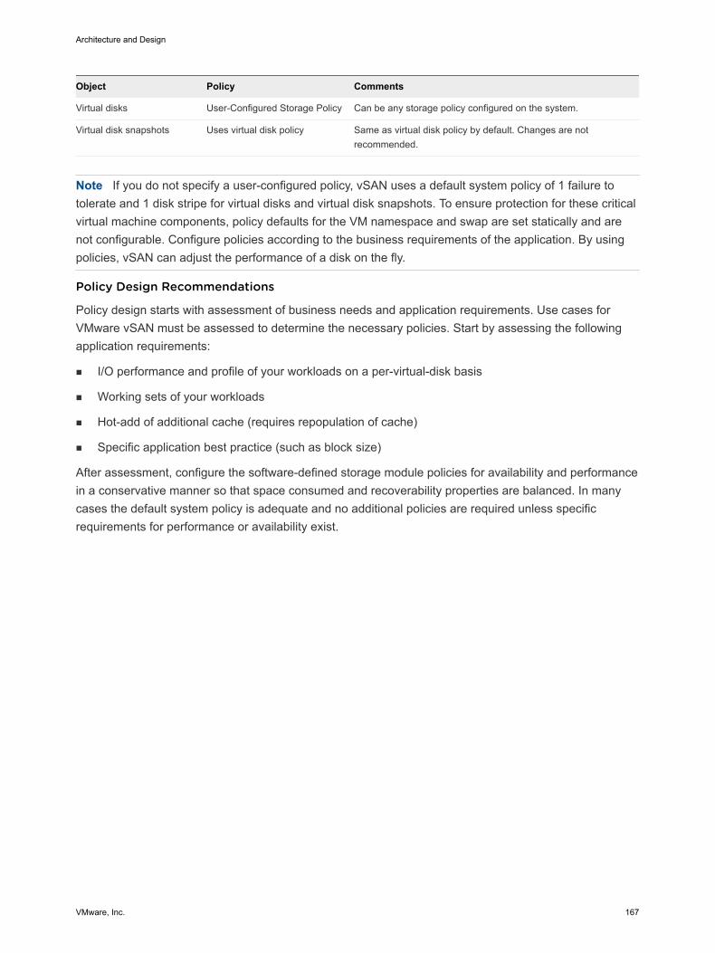
Object Policy Comments
Virtual disks User-Configured Storage Policy Can be any storage policy configured on the system.
Virtual disk snapshots Uses virtual disk policy Same as virtual disk policy by default. Changes are notrecommended.
Note If you do not specify a user-configured policy, vSAN uses a default system policy of 1 failure totolerate and 1 disk stripe for virtual disks and virtual disk snapshots. To ensure protection for these criticalvirtual machine components, policy defaults for the VM namespace and swap are set statically and arenot configurable. Configure policies according to the business requirements of the application. By usingpolicies, vSAN can adjust the performance of a disk on the fly.
Policy Design Recommendations
Policy design starts with assessment of business needs and application requirements. Use cases forVMware vSAN must be assessed to determine the necessary policies. Start by assessing the followingapplication requirements:
n I/O performance and profile of your workloads on a per-virtual-disk basis
n Working sets of your workloads
n Hot-add of additional cache (requires repopulation of cache)
n Specific application best practice (such as block size)
After assessment, configure the software-defined storage module policies for availability and performancein a conservative manner so that space consumed and recoverability properties are balanced. In manycases the default system policy is adequate and no additional policies are required unless specificrequirements for performance or availability exist.
Architecture and Design
VMware, Inc. 167
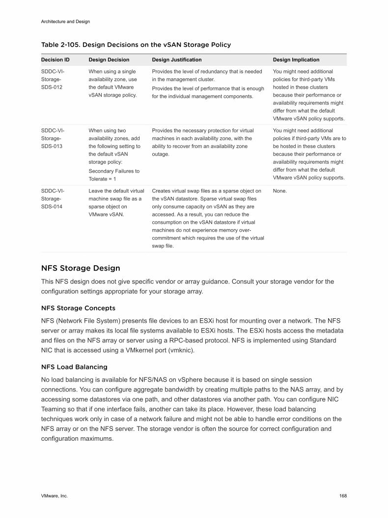
Table 2-105. Design Decisions on the vSAN Storage Policy
Decision ID Design Decision Design Justification Design Implication
SDDC-VI-Storage-SDS-012
When using a singleavailability zone, usethe default VMwarevSAN storage policy.
Provides the level of redundancy that is neededin the management cluster.
Provides the level of performance that is enoughfor the individual management components.
You might need additionalpolicies for third-party VMshosted in these clustersbecause their performance oravailability requirements mightdiffer from what the defaultVMware vSAN policy supports.
SDDC-VI-Storage-SDS-013
When using twoavailability zones, addthe following setting tothe default vSANstorage policy:
Secondary Failures toTolerate = 1
Provides the necessary protection for virtualmachines in each availability zone, with theability to recover from an availability zoneoutage.
You might need additionalpolicies if third-party VMs are tobe hosted in these clustersbecause their performance oravailability requirements mightdiffer from what the defaultVMware vSAN policy supports.
SDDC-VI-Storage-SDS-014
Leave the default virtualmachine swap file as asparse object onVMware vSAN.
Creates virtual swap files as a sparse object onthe vSAN datastore. Sparse virtual swap filesonly consume capacity on vSAN as they areaccessed. As a result, you can reduce theconsumption on the vSAN datastore if virtualmachines do not experience memory over-commitment which requires the use of the virtualswap file.
None.
NFS Storage DesignThis NFS design does not give specific vendor or array guidance. Consult your storage vendor for theconfiguration settings appropriate for your storage array.
NFS Storage Concepts
NFS (Network File System) presents file devices to an ESXi host for mounting over a network. The NFSserver or array makes its local file systems available to ESXi hosts. The ESXi hosts access the metadataand files on the NFS array or server using a RPC-based protocol. NFS is implemented using StandardNIC that is accessed using a VMkernel port (vmknic).
NFS Load Balancing
No load balancing is available for NFS/NAS on vSphere because it is based on single sessionconnections. You can configure aggregate bandwidth by creating multiple paths to the NAS array, and byaccessing some datastores via one path, and other datastores via another path. You can configure NICTeaming so that if one interface fails, another can take its place. However, these load balancingtechniques work only in case of a network failure and might not be able to handle error conditions on theNFS array or on the NFS server. The storage vendor is often the source for correct configuration andconfiguration maximums.
Architecture and Design
VMware, Inc. 168
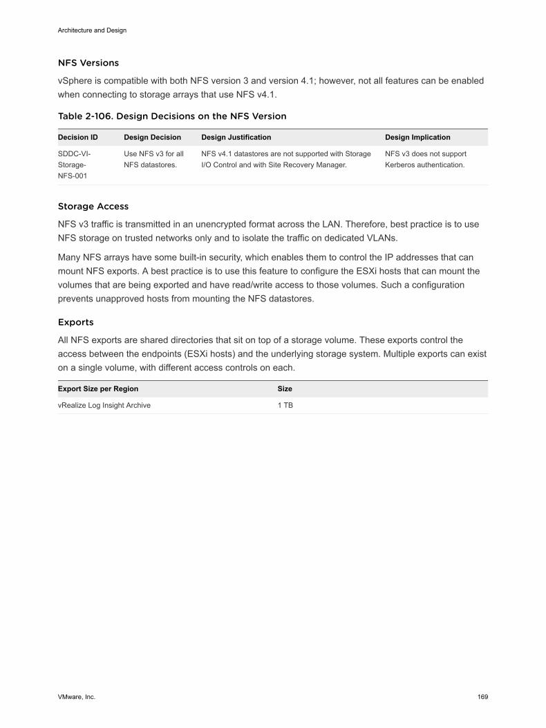
NFS Versions
vSphere is compatible with both NFS version 3 and version 4.1; however, not all features can be enabledwhen connecting to storage arrays that use NFS v4.1.
Table 2-106. Design Decisions on the NFS Version
Decision ID Design Decision Design Justification Design Implication
SDDC-VI-Storage-NFS-001
Use NFS v3 for allNFS datastores.
NFS v4.1 datastores are not supported with StorageI/O Control and with Site Recovery Manager.
NFS v3 does not supportKerberos authentication.
Storage Access
NFS v3 traffic is transmitted in an unencrypted format across the LAN. Therefore, best practice is to useNFS storage on trusted networks only and to isolate the traffic on dedicated VLANs.
Many NFS arrays have some built-in security, which enables them to control the IP addresses that canmount NFS exports. A best practice is to use this feature to configure the ESXi hosts that can mount thevolumes that are being exported and have read/write access to those volumes. Such a configurationprevents unapproved hosts from mounting the NFS datastores.
Exports
All NFS exports are shared directories that sit on top of a storage volume. These exports control theaccess between the endpoints (ESXi hosts) and the underlying storage system. Multiple exports can existon a single volume, with different access controls on each.
Export Size per Region Size
vRealize Log Insight Archive 1 TB
Architecture and Design
VMware, Inc. 169
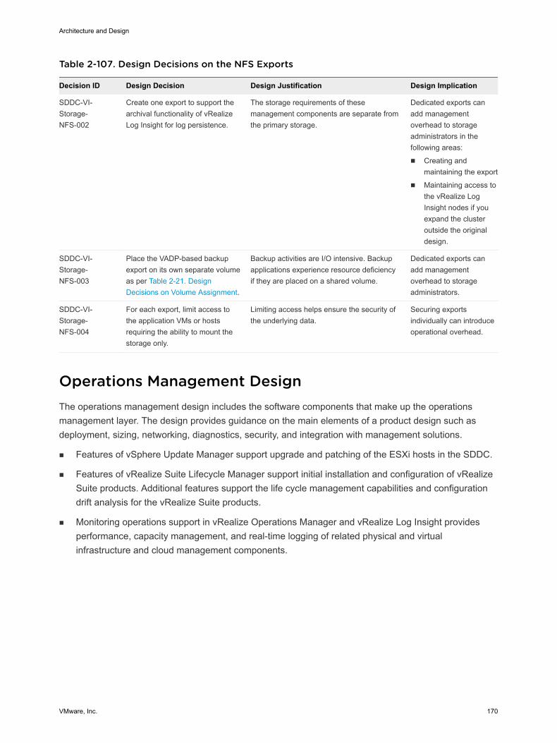
Table 2-107. Design Decisions on the NFS Exports
Decision ID Design Decision Design Justification Design Implication
SDDC-VI-Storage-NFS-002
Create one export to support thearchival functionality of vRealizeLog Insight for log persistence.
The storage requirements of thesemanagement components are separate fromthe primary storage.
Dedicated exports canadd managementoverhead to storageadministrators in thefollowing areas:
n Creating andmaintaining the export
n Maintaining access tothe vRealize LogInsight nodes if youexpand the clusteroutside the originaldesign.
SDDC-VI-Storage-NFS-003
Place the VADP-based backupexport on its own separate volumeas per Table 2-21. DesignDecisions on Volume Assignment.
Backup activities are I/O intensive. Backupapplications experience resource deficiencyif they are placed on a shared volume.
Dedicated exports canadd managementoverhead to storageadministrators.
SDDC-VI-Storage-NFS-004
For each export, limit access tothe application VMs or hostsrequiring the ability to mount thestorage only.
Limiting access helps ensure the security ofthe underlying data.
Securing exportsindividually can introduceoperational overhead.
Operations Management Design The operations management design includes the software components that make up the operationsmanagement layer. The design provides guidance on the main elements of a product design such asdeployment, sizing, networking, diagnostics, security, and integration with management solutions.
n Features of vSphere Update Manager support upgrade and patching of the ESXi hosts in the SDDC.
n Features of vRealize Suite Lifecycle Manager support initial installation and configuration of vRealizeSuite products. Additional features support the life cycle management capabilities and configurationdrift analysis for the vRealize Suite products.
n Monitoring operations support in vRealize Operations Manager and vRealize Log Insight providesperformance, capacity management, and real-time logging of related physical and virtualinfrastructure and cloud management components.
Architecture and Design
VMware, Inc. 170
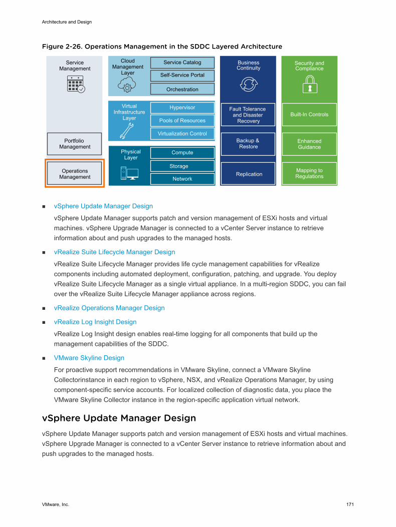
Figure 2-26. Operations Management in the SDDC Layered Architecture
ServiceManagement
Portfolio Management
OperationsManagement
CloudManagement
Layer
Service Catalog
Self-Service Portal
Orchestration
BusinessContinuity
Fault Tolerance and Disaster
Recovery
Backup & Restore
Hypervisor
Pools of Resources
Virtualization Control
VirtualInfrastructure
Layer
Compute
Storage
Network
PhysicalLayer
Replication
Security and Compliance
Mapping to Regulations
Enhanced Guidance
Built-In Controls
n vSphere Update Manager Design
vSphere Update Manager supports patch and version management of ESXi hosts and virtualmachines. vSphere Upgrade Manager is connected to a vCenter Server instance to retrieveinformation about and push upgrades to the managed hosts.
n vRealize Suite Lifecycle Manager Design
vRealize Suite Lifecycle Manager provides life cycle management capabilities for vRealizecomponents including automated deployment, configuration, patching, and upgrade. You deployvRealize Suite Lifecycle Manager as a single virtual appliance. In a multi-region SDDC, you can failover the vRealize Suite Lifecycle Manager appliance across regions.
n vRealize Operations Manager Design
n vRealize Log Insight Design
vRealize Log Insight design enables real-time logging for all components that build up themanagement capabilities of the SDDC.
n VMware Skyline Design
For proactive support recommendations in VMware Skyline, connect a VMware SkylineCollectorinstance in each region to vSphere, NSX, and vRealize Operations Manager, by usingcomponent-specific service accounts. For localized collection of diagnostic data, you place theVMware Skyline Collector instance in the region-specific application virtual network.
vSphere Update Manager Design vSphere Update Manager supports patch and version management of ESXi hosts and virtual machines.vSphere Upgrade Manager is connected to a vCenter Server instance to retrieve information about andpush upgrades to the managed hosts.
Architecture and Design
VMware, Inc. 171
vSphere Update Manager can remediate the following objects over the network:
n VMware Tools and VMware virtual machine hardware upgrade operations
n ESXi host patching operations
n ESXi host upgrade operations
n Physical Design of vSphere Update Manager
n Logical Design of vSphere Update Manager
You configure vSphere Update Manager to apply updates on the management components of theSDDC according to the objectives of this design.
Physical Design of vSphere Update Manager You use the vSphere Update Manager service on each vCenter Server Appliance. You deploy a vSphereUpdate Manager Download Service (UMDS) in Region A and Region B to download and stage upgradeand patch data.
Networking and Application Design
You can use the vSphere Update Manager as a service of the vCenter Server Appliance. The UpdateManager server and client components are a part of the vCenter Server Appliance.
You can connect only one vCenter Server instance to a vSphere Update Manager instance.
Because this design uses multiple vCenter Server instances, you must configure a separate vSphereUpdate Manager for each vCenter Server. To save the overhead of downloading updates on multiplevSphere Update Manager instances and to restrict the access to the external network from vSphereUpdate Manager and vCenter Server, deploy a UMDS in each region.
UMDS downloads upgrades, patch binaries and patch metadata, and stages the downloaded data on aWeb server. The local Update Manager servers download the patches from UMDS.
Architecture and Design
VMware, Inc. 172
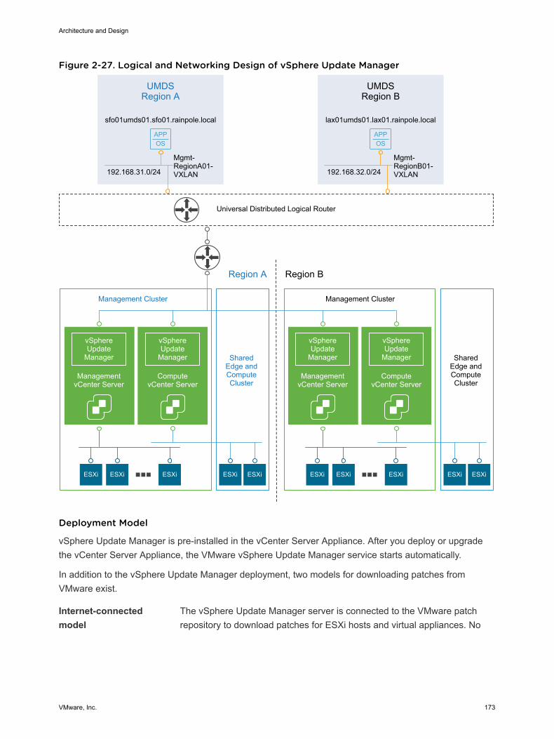
Figure 2-27. Logical and Networking Design of vSphere Update Manager
APPOS
APPOS
UMDSRegion A
Management Cluster
SharedEdge andComputeCluster
ESXi ESXi ESXi ESXiESXi
Management Cluster
SharedEdge andComputeCluster
ESXi ESXi ESXi ESXiESXi
vSphereUpdate
Manager
ManagementvCenter Server
vSphereUpdate
Manager
ComputevCenter Server
192.168.31.0/24
Mgmt-RegionA01-VXLAN
sfo01umds01.sfo01.rainpole.local
UMDSRegion B
192.168.32.0/24
Mgmt-RegionB01-VXLAN
lax01umds01.lax01.rainpole.local
Universal Distributed Logical Router
Region A Region B
vSphereUpdate
Manager
ManagementvCenter Server
vSphereUpdate
Manager
ComputevCenter Server
Deployment Model
vSphere Update Manager is pre-installed in the vCenter Server Appliance. After you deploy or upgradethe vCenter Server Appliance, the VMware vSphere Update Manager service starts automatically.
In addition to the vSphere Update Manager deployment, two models for downloading patches fromVMware exist.
Internet-connectedmodel
The vSphere Update Manager server is connected to the VMware patchrepository to download patches for ESXi hosts and virtual appliances. No
Architecture and Design
VMware, Inc. 173
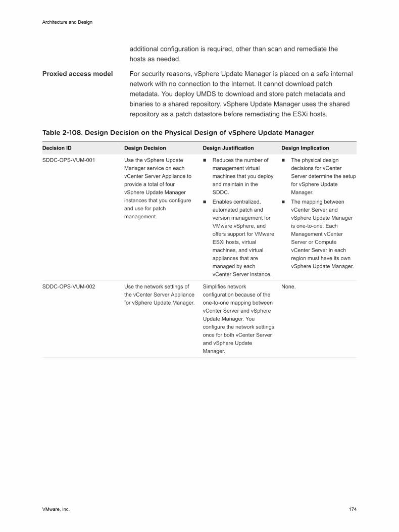
additional configuration is required, other than scan and remediate thehosts as needed.
Proxied access model For security reasons, vSphere Update Manager is placed on a safe internalnetwork with no connection to the Internet. It cannot download patchmetadata. You deploy UMDS to download and store patch metadata andbinaries to a shared repository. vSphere Update Manager uses the sharedrepository as a patch datastore before remediating the ESXi hosts.
Table 2-108. Design Decision on the Physical Design of vSphere Update Manager
Decision ID Design Decision Design Justification Design Implication
SDDC-OPS-VUM-001 Use the vSphere UpdateManager service on eachvCenter Server Appliance toprovide a total of fourvSphere Update Managerinstances that you configureand use for patchmanagement.
n Reduces the number ofmanagement virtualmachines that you deployand maintain in theSDDC.
n Enables centralized,automated patch andversion management forVMware vSphere, andoffers support for VMwareESXi hosts, virtualmachines, and virtualappliances that aremanaged by eachvCenter Server instance.
n The physical designdecisions for vCenterServer determine the setupfor vSphere UpdateManager.
n The mapping betweenvCenter Server andvSphere Update Manageris one-to-one. EachManagement vCenterServer or ComputevCenter Server in eachregion must have its ownvSphere Update Manager.
SDDC-OPS-VUM-002 Use the network settings ofthe vCenter Server Appliancefor vSphere Update Manager.
Simplifies networkconfiguration because of theone-to-one mapping betweenvCenter Server and vSphereUpdate Manager. Youconfigure the network settingsonce for both vCenter Serverand vSphere UpdateManager.
None.
Architecture and Design
VMware, Inc. 174
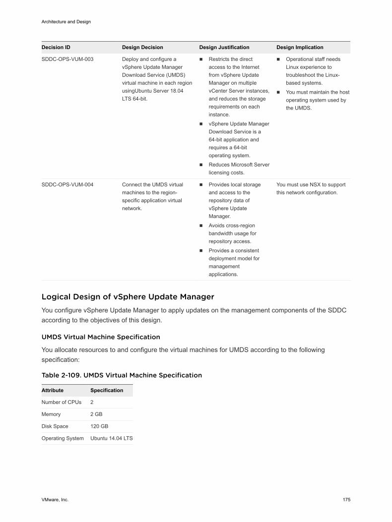
Decision ID Design Decision Design Justification Design Implication
SDDC-OPS-VUM-003 Deploy and configure avSphere Update ManagerDownload Service (UMDS)virtual machine in each regionusingUbuntu Server 18.04LTS 64-bit.
n Restricts the directaccess to the Internetfrom vSphere UpdateManager on multiplevCenter Server instances,and reduces the storagerequirements on eachinstance.
n vSphere Update ManagerDownload Service is a64-bit application andrequires a 64-bitoperating system.
n Reduces Microsoft Serverlicensing costs.
n Operational staff needsLinux experience totroubleshoot the Linux-based systems.
n You must maintain the hostoperating system used bythe UMDS.
SDDC-OPS-VUM-004 Connect the UMDS virtualmachines to the region-specific application virtualnetwork.
n Provides local storageand access to therepository data ofvSphere UpdateManager.
n Avoids cross-regionbandwidth usage forrepository access.
n Provides a consistentdeployment model formanagementapplications.
You must use NSX to supportthis network configuration.
Logical Design of vSphere Update Manager You configure vSphere Update Manager to apply updates on the management components of the SDDCaccording to the objectives of this design.
UMDS Virtual Machine Specification
You allocate resources to and configure the virtual machines for UMDS according to the followingspecification:
Table 2-109. UMDS Virtual Machine Specification
Attribute Specification
Number of CPUs 2
Memory 2 GB
Disk Space 120 GB
Operating System Ubuntu 14.04 LTS
Architecture and Design
VMware, Inc. 175
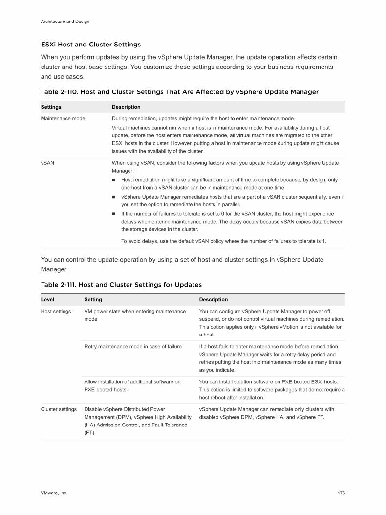
ESXi Host and Cluster Settings
When you perform updates by using the vSphere Update Manager, the update operation affects certaincluster and host base settings. You customize these settings according to your business requirementsand use cases.
Table 2-110. Host and Cluster Settings That Are Affected by vSphere Update Manager
Settings Description
Maintenance mode During remediation, updates might require the host to enter maintenance mode.
Virtual machines cannot run when a host is in maintenance mode. For availability during a hostupdate, before the host enters maintenance mode, all virtual machines are migrated to the otherESXi hosts in the cluster. However, putting a host in maintenance mode during update might causeissues with the availability of the cluster.
vSAN When using vSAN, consider the following factors when you update hosts by using vSphere UpdateManager:
n Host remediation might take a significant amount of time to complete because, by design, onlyone host from a vSAN cluster can be in maintenance mode at one time.
n vSphere Update Manager remediates hosts that are a part of a vSAN cluster sequentially, even ifyou set the option to remediate the hosts in parallel.
n If the number of failures to tolerate is set to 0 for the vSAN cluster, the host might experiencedelays when entering maintenance mode. The delay occurs because vSAN copies data betweenthe storage devices in the cluster.
To avoid delays, use the default vSAN policy where the number of failures to tolerate is 1.
You can control the update operation by using a set of host and cluster settings in vSphere UpdateManager.
Table 2-111. Host and Cluster Settings for Updates
Level Setting Description
Host settings VM power state when entering maintenancemode
You can configure vSphere Update Manager to power off,suspend, or do not control virtual machines during remediation.This option applies only if vSphere vMotion is not available fora host.
Retry maintenance mode in case of failure If a host fails to enter maintenance mode before remediation,vSphere Update Manager waits for a retry delay period andretries putting the host into maintenance mode as many timesas you indicate.
Allow installation of additional software onPXE-booted hosts
You can install solution software on PXE-booted ESXi hosts.This option is limited to software packages that do not require ahost reboot after installation.
Cluster settings Disable vSphere Distributed PowerManagement (DPM), vSphere High Availability(HA) Admission Control, and Fault Tolerance(FT)
vSphere Update Manager can remediate only clusters withdisabled vSphere DPM, vSphere HA, and vSphere FT.
Architecture and Design
VMware, Inc. 176
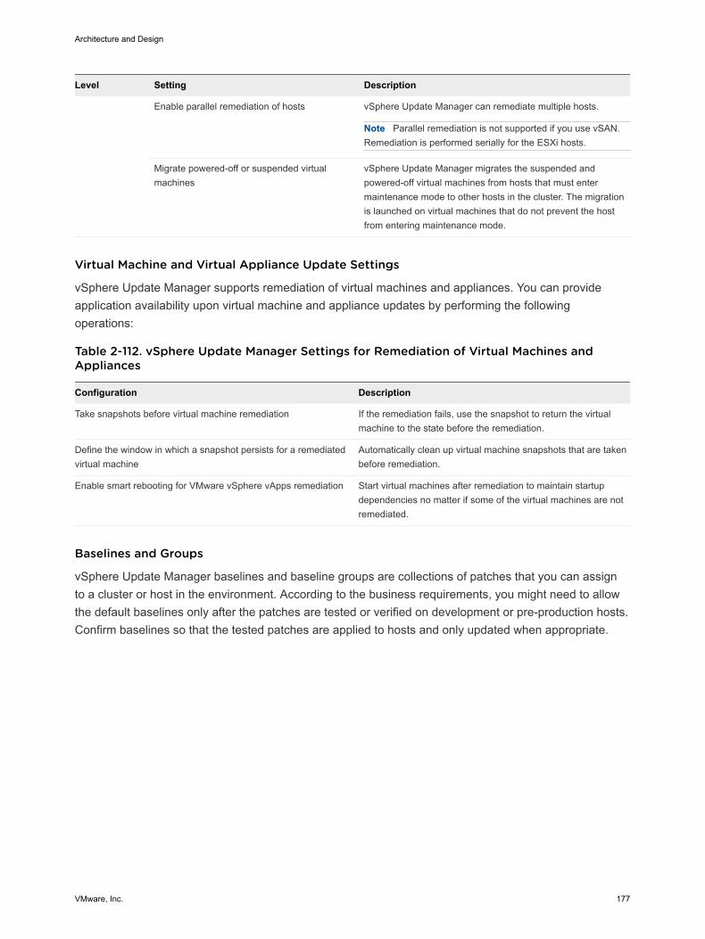
Level Setting Description
Enable parallel remediation of hosts vSphere Update Manager can remediate multiple hosts.
Note Parallel remediation is not supported if you use vSAN.Remediation is performed serially for the ESXi hosts.
Migrate powered-off or suspended virtualmachines
vSphere Update Manager migrates the suspended andpowered-off virtual machines from hosts that must entermaintenance mode to other hosts in the cluster. The migrationis launched on virtual machines that do not prevent the hostfrom entering maintenance mode.
Virtual Machine and Virtual Appliance Update Settings
vSphere Update Manager supports remediation of virtual machines and appliances. You can provideapplication availability upon virtual machine and appliance updates by performing the followingoperations:
Table 2-112. vSphere Update Manager Settings for Remediation of Virtual Machines andAppliances
Configuration Description
Take snapshots before virtual machine remediation If the remediation fails, use the snapshot to return the virtualmachine to the state before the remediation.
Define the window in which a snapshot persists for a remediatedvirtual machine
Automatically clean up virtual machine snapshots that are takenbefore remediation.
Enable smart rebooting for VMware vSphere vApps remediation Start virtual machines after remediation to maintain startupdependencies no matter if some of the virtual machines are notremediated.
Baselines and Groups
vSphere Update Manager baselines and baseline groups are collections of patches that you can assignto a cluster or host in the environment. According to the business requirements, you might need to allowthe default baselines only after the patches are tested or verified on development or pre-production hosts.Confirm baselines so that the tested patches are applied to hosts and only updated when appropriate.
Architecture and Design
VMware, Inc. 177
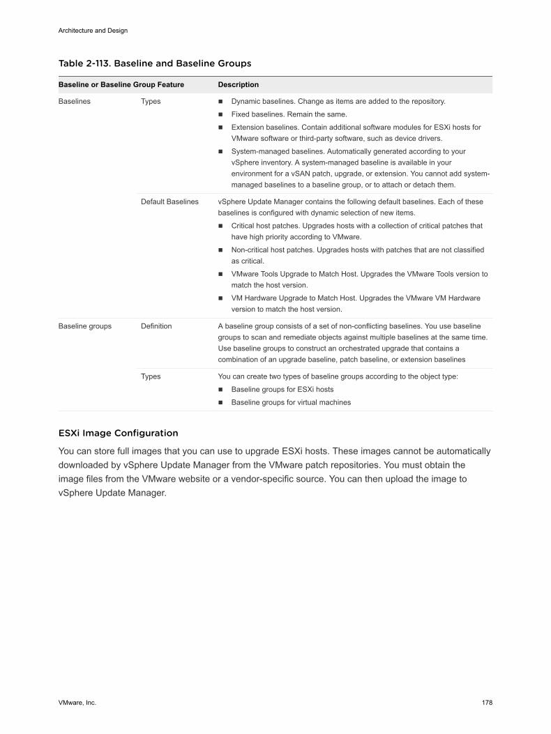
Table 2-113. Baseline and Baseline Groups
Baseline or Baseline Group Feature Description
Baselines Types n Dynamic baselines. Change as items are added to the repository.
n Fixed baselines. Remain the same.
n Extension baselines. Contain additional software modules for ESXi hosts forVMware software or third-party software, such as device drivers.
n System-managed baselines. Automatically generated according to yourvSphere inventory. A system-managed baseline is available in yourenvironment for a vSAN patch, upgrade, or extension. You cannot add system-managed baselines to a baseline group, or to attach or detach them.
Default Baselines vSphere Update Manager contains the following default baselines. Each of thesebaselines is configured with dynamic selection of new items.
n Critical host patches. Upgrades hosts with a collection of critical patches thathave high priority according to VMware.
n Non-critical host patches. Upgrades hosts with patches that are not classifiedas critical.
n VMware Tools Upgrade to Match Host. Upgrades the VMware Tools version tomatch the host version.
n VM Hardware Upgrade to Match Host. Upgrades the VMware VM Hardwareversion to match the host version.
Baseline groups Definition A baseline group consists of a set of non-conflicting baselines. You use baselinegroups to scan and remediate objects against multiple baselines at the same time.Use baseline groups to construct an orchestrated upgrade that contains acombination of an upgrade baseline, patch baseline, or extension baselines
Types You can create two types of baseline groups according to the object type:
n Baseline groups for ESXi hosts
n Baseline groups for virtual machines
ESXi Image Configuration
You can store full images that you can use to upgrade ESXi hosts. These images cannot be automaticallydownloaded by vSphere Update Manager from the VMware patch repositories. You must obtain theimage files from the VMware website or a vendor-specific source. You can then upload the image tovSphere Update Manager.
Architecture and Design
VMware, Inc. 178
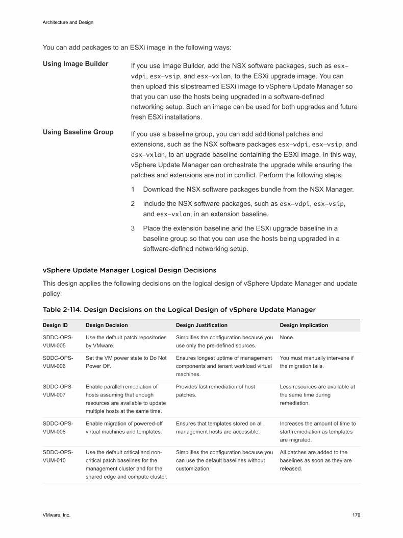
You can add packages to an ESXi image in the following ways:
Using Image Builder If you use Image Builder, add the NSX software packages, such as esx-vdpi, esx-vsip, and esx-vxlan, to the ESXi upgrade image. You canthen upload this slipstreamed ESXi image to vSphere Update Manager sothat you can use the hosts being upgraded in a software-definednetworking setup. Such an image can be used for both upgrades and futurefresh ESXi installations.
Using Baseline Group If you use a baseline group, you can add additional patches andextensions, such as the NSX software packages esx-vdpi, esx-vsip, andesx-vxlan, to an upgrade baseline containing the ESXi image. In this way,vSphere Update Manager can orchestrate the upgrade while ensuring thepatches and extensions are not in conflict. Perform the following steps:
1 Download the NSX software packages bundle from the NSX Manager.
2 Include the NSX software packages, such as esx-vdpi, esx-vsip,and esx-vxlan, in an extension baseline.
3 Place the extension baseline and the ESXi upgrade baseline in abaseline group so that you can use the hosts being upgraded in asoftware-defined networking setup.
vSphere Update Manager Logical Design Decisions
This design applies the following decisions on the logical design of vSphere Update Manager and updatepolicy:
Table 2-114. Design Decisions on the Logical Design of vSphere Update Manager
Design ID Design Decision Design Justification Design Implication
SDDC-OPS-VUM-005
Use the default patch repositoriesby VMware.
Simplifies the configuration because youuse only the pre-defined sources.
None.
SDDC-OPS-VUM-006
Set the VM power state to Do NotPower Off.
Ensures longest uptime of managementcomponents and tenant workload virtualmachines.
You must manually intervene ifthe migration fails.
SDDC-OPS-VUM-007
Enable parallel remediation ofhosts assuming that enoughresources are available to updatemultiple hosts at the same time.
Provides fast remediation of hostpatches.
Less resources are available atthe same time duringremediation.
SDDC-OPS-VUM-008
Enable migration of powered-offvirtual machines and templates.
Ensures that templates stored on allmanagement hosts are accessible.
Increases the amount of time tostart remediation as templatesare migrated.
SDDC-OPS-VUM-010
Use the default critical and non-critical patch baselines for themanagement cluster and for theshared edge and compute cluster.
Simplifies the configuration because youcan use the default baselines withoutcustomization.
All patches are added to thebaselines as soon as they arereleased.
Architecture and Design
VMware, Inc. 179
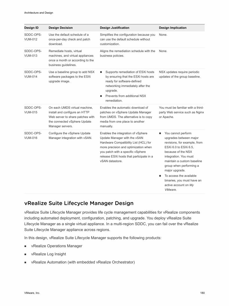
Design ID Design Decision Design Justification Design Implication
SDDC-OPS-VUM-012
Use the default schedule of aonce-per-day check and patchdownload.
Simplifies the configuration because youcan use the default schedule withoutcustomization.
None.
SDDC-OPS-VUM-013
Remediate hosts, virtualmachines, and virtual appliancesonce a month or according to thebusiness guidelines.
Aligns the remediation schedule with thebusiness policies.
None.
SDDC-OPS-VUM-014
Use a baseline group to add NSXsoftware packages to the ESXiupgrade image.
n Supports remediation of ESXi hostsby ensuring that the ESXi hosts areready for software-definednetworking immediately after theupgrade.
n Prevents from additional NSXremediation.
NSX updates require periodicupdates of the group baseline.
SDDC-OPS-VUM-015
On each UMDS virtual machine,install and configure an HTTPWeb server to share patches withthe connected vSphere UpdateManager servers.
Enables the automatic download ofpatches on vSphere Update Managerfrom UMDS. The alternative is to copymedia from one place to anothermanually.
You must be familiar with a third-party Web service such as Nginxor Apache.
SDDC-OPS-VUM-016
Configure the vSphere UpdateManager integration with vSAN.
Enables the integration of vSphereUpdate Manager with the vSANHardware Compatibility List (HCL) formore precision and optimization whenyou patch with a specific vSphererelease ESXi hosts that participate in avSAN datastore.
n You cannot performupgrades between majorrevisions, for example, fromESXi 6.0 to ESXi 6.5,because of the NSXintegration. You mustmaintain a custom baselinegroup when performing amajor upgrade.
n To access the availablebinaries, you must have anactive account on MyVMware.
vRealize Suite Lifecycle Manager Design vRealize Suite Lifecycle Manager provides life cycle management capabilities for vRealize componentsincluding automated deployment, configuration, patching, and upgrade. You deploy vRealize SuiteLifecycle Manager as a single virtual appliance. In a multi-region SDDC, you can fail over the vRealizeSuite Lifecycle Manager appliance across regions.
In this design, vRealize Suite Lifecycle Manager supports the following products:
n vRealize Operations Manager
n vRealize Log Insight
n vRealize Automation (with embedded vRealize Orchestrator)
Architecture and Design
VMware, Inc. 180
n vRealize Business for Cloud
n Logical Design of vRealize Suite Lifecycle Manager
To orchestrate the deployment, patching, upgrade, and configuration drift analysis of the vRealizeproducts in the SDDC, vRealize Suite Lifecycle Manager communicates with each ManagementvCenter Server instance in the SDDC.
n Physical Design for vRealize Suite Lifecycle Manager
To enable vRealize product deployments in the SDDC, you deploy the vRealize Suite LifecycleManager appliance and configure settings, such as vCenter Server endpoints, logical data centers,and product support.
n Networking Design of vRealize Suite Lifecycle Manager
For secure access to the UI and API and for failover of vRealize Suite Lifecycle Manager, you placethe appliance in the shared cross-region application virtual network.
n Environment Management Design for vRealize Suite Lifecycle Manager
To deploy the vRealize products by using vRealize Suite Lifecycle Manager, you configure datacenters, product support, environment structures, and product configuration drift.
n Information Security and Access Design in vRealize Suite Lifecycle Manager
You protect the vRealize Suite Lifecycle Manager deployment by configuring the authentication andsecure communication with the other components in the SDDC. You dedicate a service account tothe communication between vRealize Suite Lifecycle Manager and vCenter Server.
n Disaster Recovery of vRealize Suite Lifecycle Manager
To retain operation when a disaster occurs, this design supports failover of vRealize Suite LifecycleManager between regions.
Logical Design of vRealize Suite Lifecycle Manager To orchestrate the deployment, patching, upgrade, and configuration drift analysis of the vRealizeproducts in the SDDC, vRealize Suite Lifecycle Manager communicates with each Management vCenterServer instance in the SDDC.
vRealize Suite Lifecycle Manager consists of a single virtual appliance that deploys and upgrades thevRealize components across the virtual infrastructure that is controlled by one or more vCenter Serverinstances.
vRealize Suite Lifecycle Manager separately controls the life cycle of cross-region components, Region Aspecific components, and Region B specific components.
Architecture and Design
VMware, Inc. 181
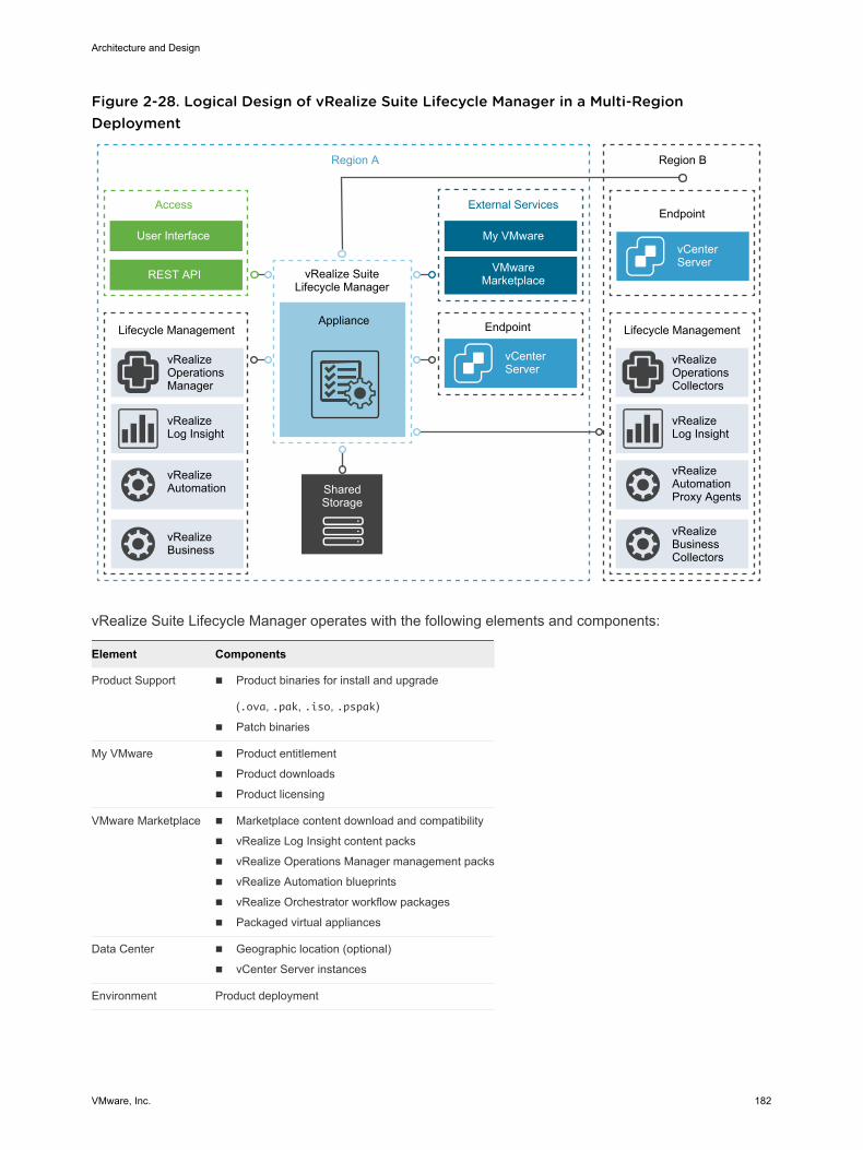
Figure 2-28. Logical Design of vRealize Suite Lifecycle Manager in a Multi-RegionDeployment
vRealizeAutomation
vRealizeLog Insight
vRealizeOperationsManager
Lifecycle Management Lifecycle Management
SharedStorage
Appliance
vRealize SuiteLifecycle Manager
vCenterServer
Endpoint
VMware Marketplace
My VMware
External Services
REST API
User Interface
Access
Region A
vCenterServer
vRealizeBusinessCollectors
vRealizeAutomationProxy Agents
vRealizeLog Insight
vRealizeOperationsCollectors
Region B
Endpoint
vRealizeBusiness
vRealize Suite Lifecycle Manager operates with the following elements and components:
Element Components
Product Support n Product binaries for install and upgrade
(.ova, .pak, .iso, .pspak)
n Patch binaries
My VMware n Product entitlement
n Product downloads
n Product licensing
VMware Marketplace n Marketplace content download and compatibility
n vRealize Log Insight content packs
n vRealize Operations Manager management packs
n vRealize Automation blueprints
n vRealize Orchestrator workflow packages
n Packaged virtual appliances
Data Center n Geographic location (optional)
n vCenter Server instances
Environment Product deployment
Architecture and Design
VMware, Inc. 182
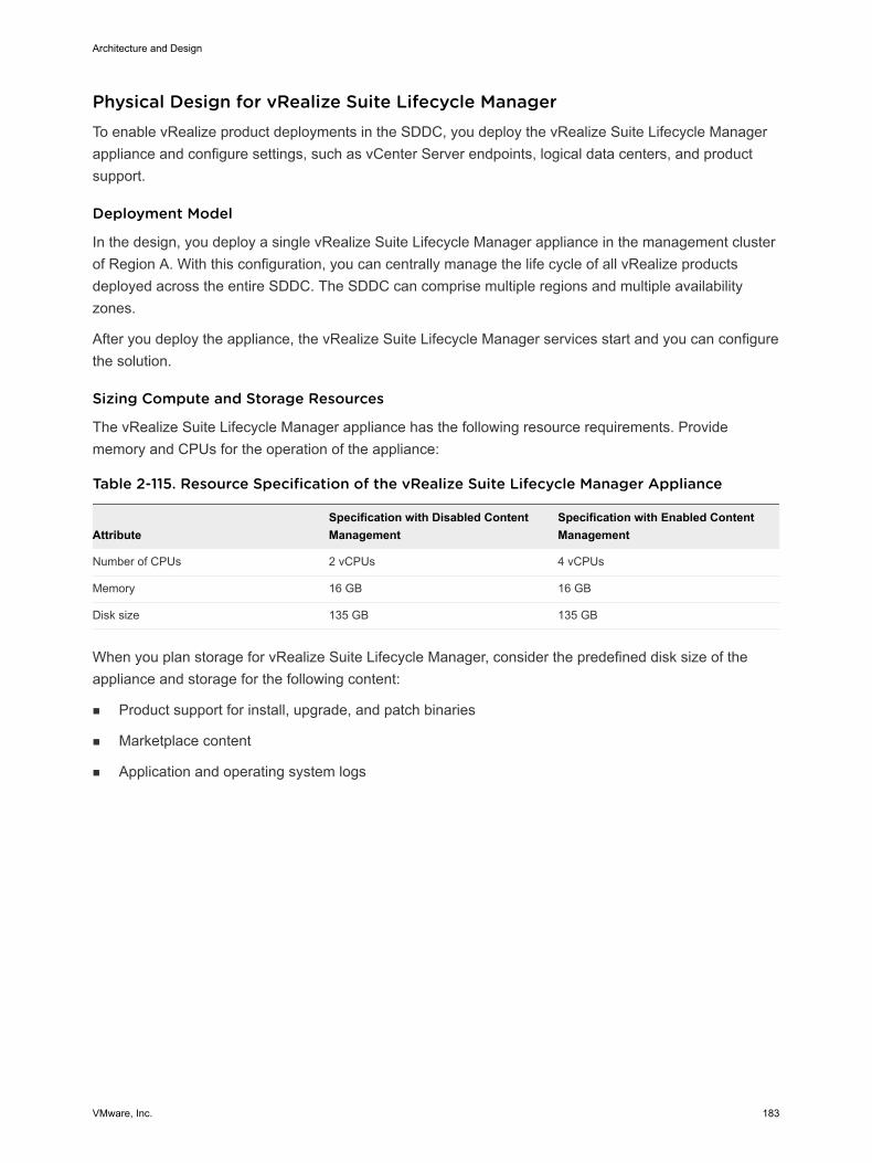
Physical Design for vRealize Suite Lifecycle Manager To enable vRealize product deployments in the SDDC, you deploy the vRealize Suite Lifecycle Managerappliance and configure settings, such as vCenter Server endpoints, logical data centers, and productsupport.
Deployment Model
In the design, you deploy a single vRealize Suite Lifecycle Manager appliance in the management clusterof Region A. With this configuration, you can centrally manage the life cycle of all vRealize productsdeployed across the entire SDDC. The SDDC can comprise multiple regions and multiple availabilityzones.
After you deploy the appliance, the vRealize Suite Lifecycle Manager services start and you can configurethe solution.
Sizing Compute and Storage Resources
The vRealize Suite Lifecycle Manager appliance has the following resource requirements. Providememory and CPUs for the operation of the appliance:
Table 2-115. Resource Specification of the vRealize Suite Lifecycle Manager Appliance
AttributeSpecification with Disabled ContentManagement
Specification with Enabled ContentManagement
Number of CPUs 2 vCPUs 4 vCPUs
Memory 16 GB 16 GB
Disk size 135 GB 135 GB
When you plan storage for vRealize Suite Lifecycle Manager, consider the predefined disk size of theappliance and storage for the following content:
n Product support for install, upgrade, and patch binaries
n Marketplace content
n Application and operating system logs
Architecture and Design
VMware, Inc. 183
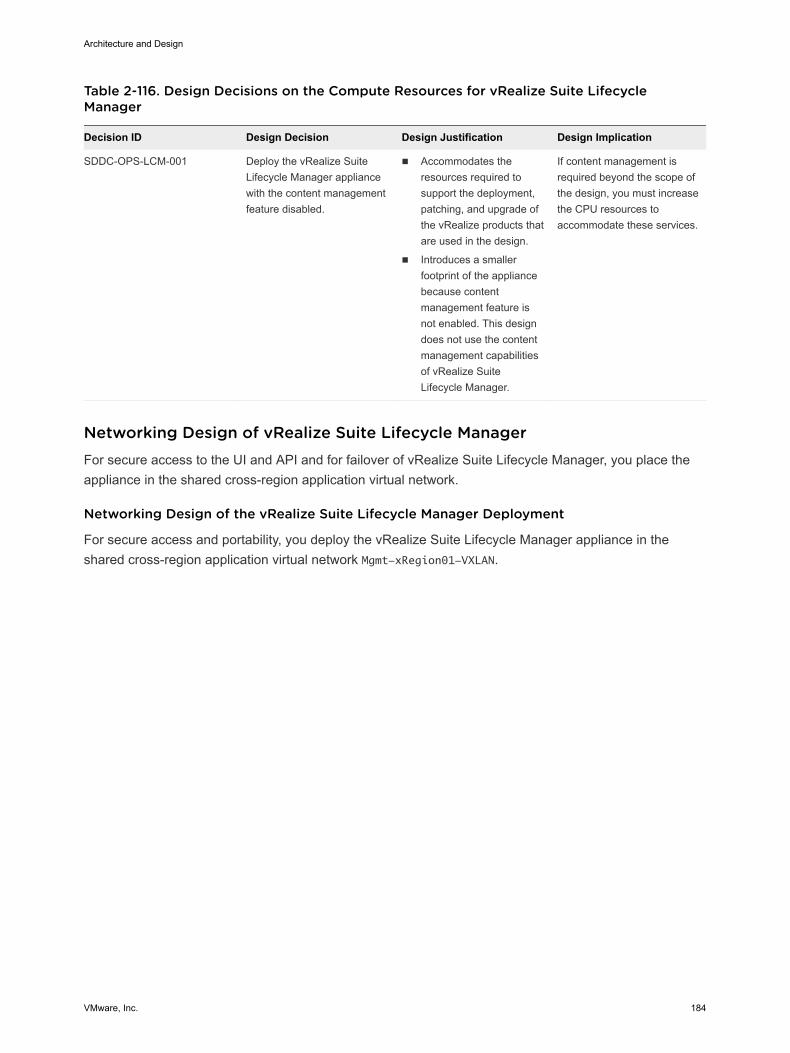
Table 2-116. Design Decisions on the Compute Resources for vRealize Suite LifecycleManager
Decision ID Design Decision Design Justification Design Implication
SDDC-OPS-LCM-001 Deploy the vRealize SuiteLifecycle Manager appliancewith the content managementfeature disabled.
n Accommodates theresources required tosupport the deployment,patching, and upgrade ofthe vRealize products thatare used in the design.
n Introduces a smallerfootprint of the appliancebecause contentmanagement feature isnot enabled. This designdoes not use the contentmanagement capabilitiesof vRealize SuiteLifecycle Manager.
If content management isrequired beyond the scope ofthe design, you must increasethe CPU resources toaccommodate these services.
Networking Design of vRealize Suite Lifecycle Manager For secure access to the UI and API and for failover of vRealize Suite Lifecycle Manager, you place theappliance in the shared cross-region application virtual network.
Networking Design of the vRealize Suite Lifecycle Manager Deployment
For secure access and portability, you deploy the vRealize Suite Lifecycle Manager appliance in theshared cross-region application virtual network Mgmt-xRegion01-VXLAN.
Architecture and Design
VMware, Inc. 184
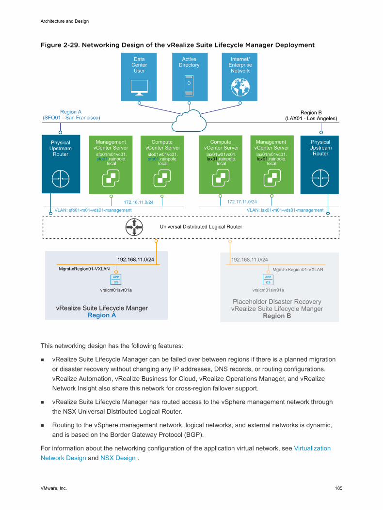
Figure 2-29. Networking Design of the vRealize Suite Lifecycle Manager Deployment
APP
OSAPP
OS
Universal Distributed Logical Router
DataCenterUser
ActiveDirectory
Internet/EnterpriseNetwork
Region A(SFO01 - San Francisco)
Management vCenter Serverlax01m01vc01.lax01.rainpole.
local
Compute vCenter Serverlax01w01vc01.lax01.rainpole.
local
VLAN: sfo01-m01-vds01-management
172.16.11.0/24
VLAN: lax01-m01-vds01-management.
172.17.11.0/24
Management vCenter Server
sfo01m01vc01.sfo01.rainpole.
local
Compute vCenter Serversfo01w01vc01.sfo01.rainpole.
local
PhysicalUpstream
Router
vrslcm01svr01a
192.168.11.0/24
Mgmt-xRegion01-VXLAN
vRealize Suite Lifecycle MangerRegion A
Region B(LAX01 - Los Angeles)
PhysicalUpstream
Router
vrslcm01svr01a
192.168.11.0/24
Placeholder Disaster RecoveryvRealize Suite Lifecycle Manger
Region B
Mgmt-xRegion01-VXLAN
This networking design has the following features:
n vRealize Suite Lifecycle Manager can be failed over between regions if there is a planned migrationor disaster recovery without changing any IP addresses, DNS records, or routing configurations.vRealize Automation, vRealize Business for Cloud, vRealize Operations Manager, and vRealizeNetwork Insight also share this network for cross-region failover support.
n vRealize Suite Lifecycle Manager has routed access to the vSphere management network throughthe NSX Universal Distributed Logical Router.
n Routing to the vSphere management network, logical networks, and external networks is dynamic,and is based on the Border Gateway Protocol (BGP).
For information about the networking configuration of the application virtual network, see VirtualizationNetwork Design and NSX Design .
Architecture and Design
VMware, Inc. 185
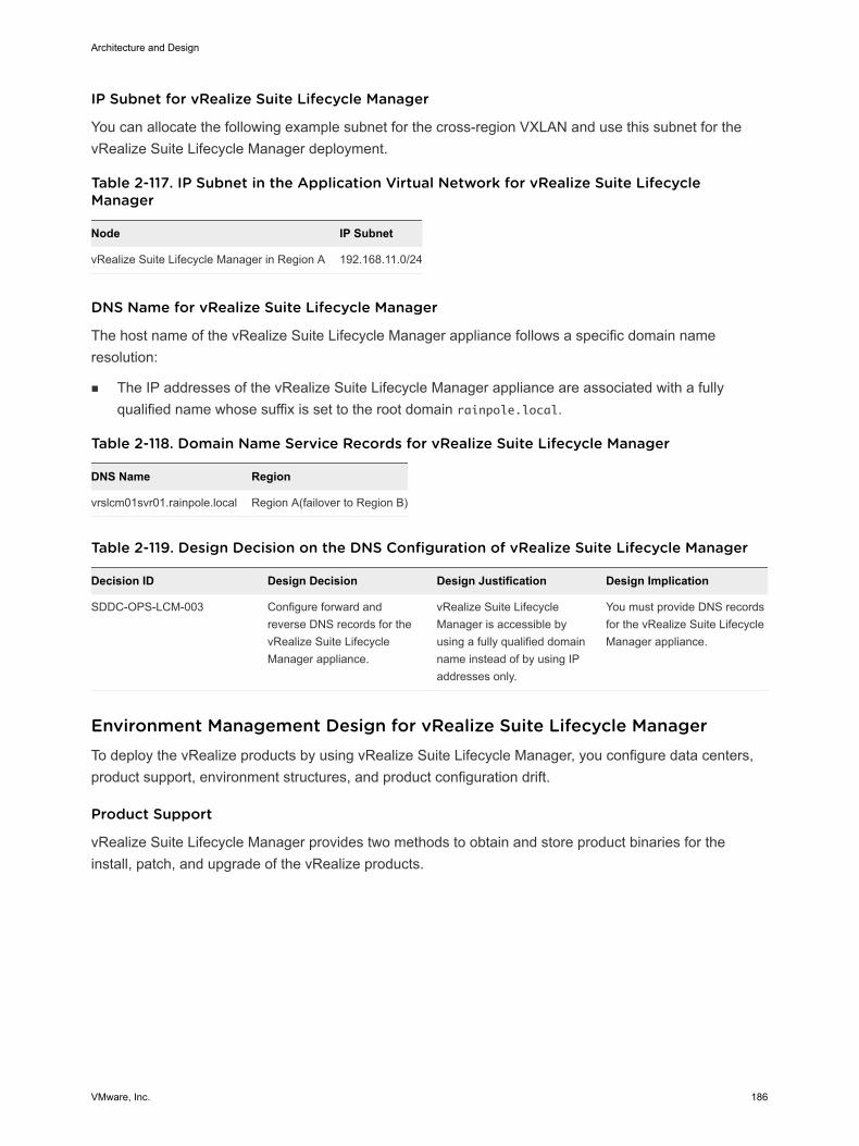
IP Subnet for vRealize Suite Lifecycle Manager
You can allocate the following example subnet for the cross-region VXLAN and use this subnet for thevRealize Suite Lifecycle Manager deployment.
Table 2-117. IP Subnet in the Application Virtual Network for vRealize Suite LifecycleManager
Node IP Subnet
vRealize Suite Lifecycle Manager in Region A 192.168.11.0/24
DNS Name for vRealize Suite Lifecycle Manager
The host name of the vRealize Suite Lifecycle Manager appliance follows a specific domain nameresolution:
n The IP addresses of the vRealize Suite Lifecycle Manager appliance are associated with a fullyqualified name whose suffix is set to the root domain rainpole.local.
Table 2-118. Domain Name Service Records for vRealize Suite Lifecycle Manager
DNS Name Region
vrslcm01svr01.rainpole.local Region A(failover to Region B)
Table 2-119. Design Decision on the DNS Configuration of vRealize Suite Lifecycle Manager
Decision ID Design Decision Design Justification Design Implication
SDDC-OPS-LCM-003 Configure forward andreverse DNS records for thevRealize Suite LifecycleManager appliance.
vRealize Suite LifecycleManager is accessible byusing a fully qualified domainname instead of by using IPaddresses only.
You must provide DNS recordsfor the vRealize Suite LifecycleManager appliance.
Environment Management Design for vRealize Suite Lifecycle Manager To deploy the vRealize products by using vRealize Suite Lifecycle Manager, you configure data centers,product support, environment structures, and product configuration drift.
Product Support
vRealize Suite Lifecycle Manager provides two methods to obtain and store product binaries for theinstall, patch, and upgrade of the vRealize products.
Architecture and Design
VMware, Inc. 186
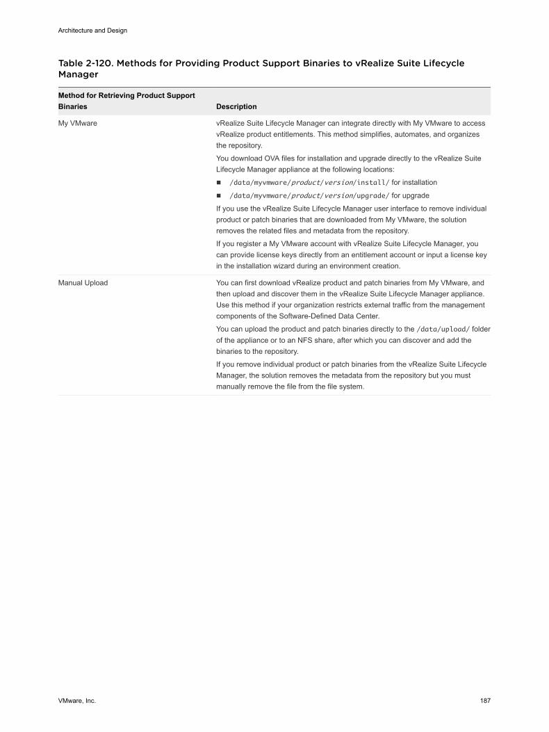
Table 2-120. Methods for Providing Product Support Binaries to vRealize Suite LifecycleManager
Method for Retrieving Product SupportBinaries Description
My VMware vRealize Suite Lifecycle Manager can integrate directly with My VMware to accessvRealize product entitlements. This method simplifies, automates, and organizesthe repository.
You download OVA files for installation and upgrade directly to the vRealize SuiteLifecycle Manager appliance at the following locations:
n /data/myvmware/product/version/install/ for installation
n /data/myvmware/product/version/upgrade/ for upgrade
If you use the vRealize Suite Lifecycle Manager user interface to remove individualproduct or patch binaries that are downloaded from My VMware, the solutionremoves the related files and metadata from the repository.
If you register a My VMware account with vRealize Suite Lifecycle Manager, youcan provide license keys directly from an entitlement account or input a license keyin the installation wizard during an environment creation.
Manual Upload You can first download vRealize product and patch binaries from My VMware, andthen upload and discover them in the vRealize Suite Lifecycle Manager appliance.Use this method if your organization restricts external traffic from the managementcomponents of the Software-Defined Data Center.
You can upload the product and patch binaries directly to the /data/upload/ folderof the appliance or to an NFS share, after which you can discover and add thebinaries to the repository.
If you remove individual product or patch binaries from the vRealize Suite LifecycleManager, the solution removes the metadata from the repository but you mustmanually remove the file from the file system.
Architecture and Design
VMware, Inc. 187
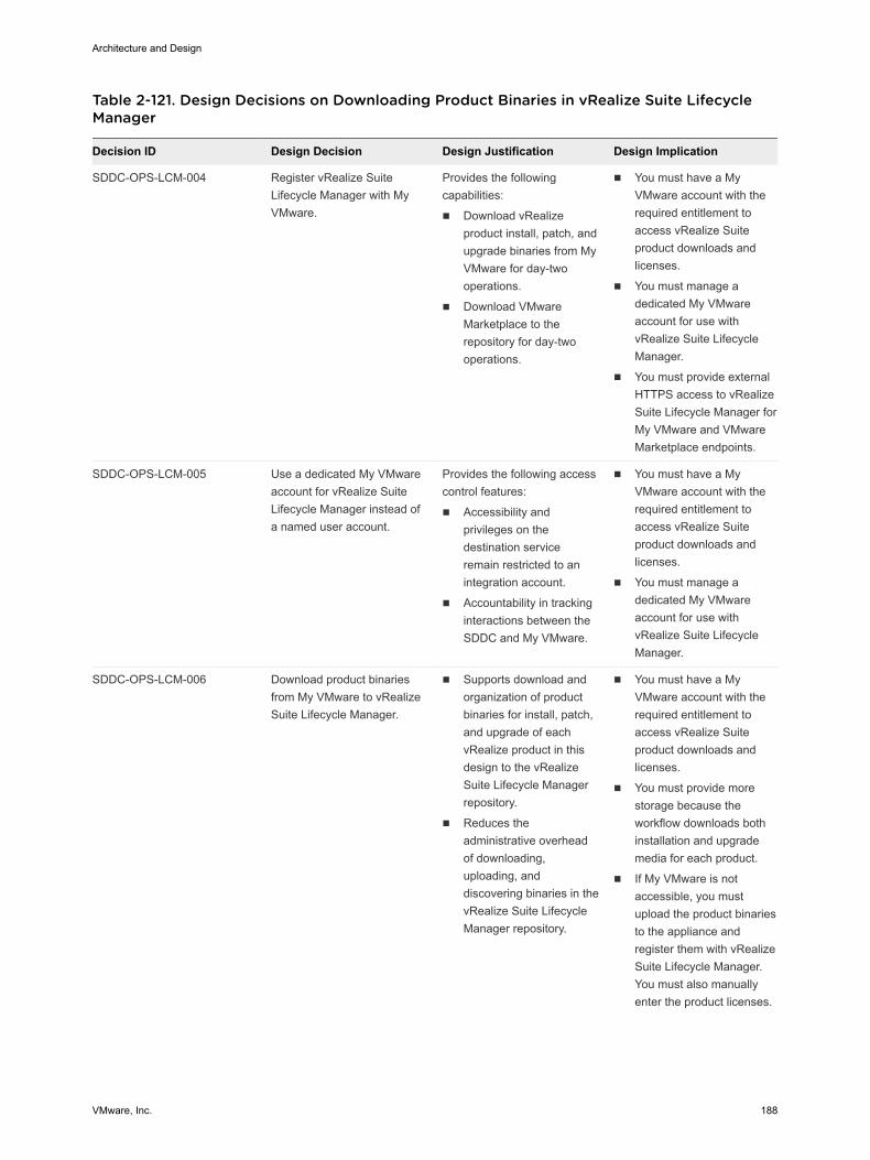
Table 2-121. Design Decisions on Downloading Product Binaries in vRealize Suite LifecycleManager
Decision ID Design Decision Design Justification Design Implication
SDDC-OPS-LCM-004 Register vRealize SuiteLifecycle Manager with MyVMware.
Provides the followingcapabilities:
n Download vRealizeproduct install, patch, andupgrade binaries from MyVMware for day-twooperations.
n Download VMwareMarketplace to therepository for day-twooperations.
n You must have a MyVMware account with therequired entitlement toaccess vRealize Suiteproduct downloads andlicenses.
n You must manage adedicated My VMwareaccount for use withvRealize Suite LifecycleManager.
n You must provide externalHTTPS access to vRealizeSuite Lifecycle Manager forMy VMware and VMwareMarketplace endpoints.
SDDC-OPS-LCM-005 Use a dedicated My VMwareaccount for vRealize SuiteLifecycle Manager instead ofa named user account.
Provides the following accesscontrol features:
n Accessibility andprivileges on thedestination serviceremain restricted to anintegration account.
n Accountability in trackinginteractions between theSDDC and My VMware.
n You must have a MyVMware account with therequired entitlement toaccess vRealize Suiteproduct downloads andlicenses.
n You must manage adedicated My VMwareaccount for use withvRealize Suite LifecycleManager.
SDDC-OPS-LCM-006 Download product binariesfrom My VMware to vRealizeSuite Lifecycle Manager.
n Supports download andorganization of productbinaries for install, patch,and upgrade of eachvRealize product in thisdesign to the vRealizeSuite Lifecycle Managerrepository.
n Reduces theadministrative overheadof downloading,uploading, anddiscovering binaries in thevRealize Suite LifecycleManager repository.
n You must have a MyVMware account with therequired entitlement toaccess vRealize Suiteproduct downloads andlicenses.
n You must provide morestorage because theworkflow downloads bothinstallation and upgrademedia for each product.
n If My VMware is notaccessible, you mustupload the product binariesto the appliance andregister them with vRealizeSuite Lifecycle Manager.You must also manuallyenter the product licenses.
Architecture and Design
VMware, Inc. 188
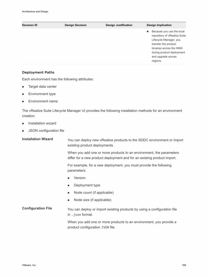
Decision ID Design Decision Design Justification Design Implication
n Because you use the localrepository of vRealize SuiteLifecycle Manager, youtransfer the productbinaries across the WANduring product deploymentand upgrade acrossregions.
Deployment Paths
Each environment has the following attributes:
n Target data center
n Environment type
n Environment name
The vRealize Suite Lifecycle Manager UI provides the following installation methods for an environmentcreation.
n Installation wizard
n JSON configuration file
Installation Wizard You can deploy new vRealize products to the SDDC environment or importexisting product deployments.
When you add one or more products to an environment, the parametersdiffer for a new product deployment and for an existing product import.
For example, for a new deployment, you must provide the followingparameters:
n Version
n Deployment type
n Node count (if applicable)
n Node size (if applicable)
Configuration File You can deploy or import existing products by using a configuration filein .json format.
When you add one or more products to an environment, you provide aproduct configuration JSON file.
Architecture and Design
VMware, Inc. 189
Marketplace Integration
You can use vRealize Suite Lifecycle Manager to add and manage content from VMware Marketplace.After you download Marketplace content, you can direct the content deployment to your SDDC directlyfrom vRealize Suite Lifecycle Manager.
To use the integration with the VMware Marketplace, you must register the vRealize Suite LifecycleManager appliance with My VMware and the appliance must have Internet access.
You can download content packs from the Marketplace in vRealize Suite Lifecycle Manager for integrationin the SDDC. For information about the content packs and versions in this design, see VMware ValidatedDesign for Software-Defined Data Center Release Notes.
You can also use vRealize Suite Lifecycle Manager to download and install vRealize Operationsmanagement packs from the Marketplace. Most management packs for the SDDC are preinstalled in theproduct. For information about the management packs and versions in this design, see VMware ValidatedDesign for Software-Defined Data Center Release Notes
Environments and Data Centers
vRealize Suite Lifecycle Manager supports the deployment and upgrade of vRealize Suite products in alogical environment grouping.
These products are as follows:
n vRealize Operations Manager
n vRealize Log Insight
n vRealize Automation (with embedded vRealize Orchestrator)
n vRealize Business for Cloud
Environments are deployed to a data center object in vRealize Suite Lifecycle Manager. Eachenvironment can contain only one instance of a vRealize Suite product. For example, only one vRealizeLog Insight cluster can exist in an environment. However, you can use vRealize Suite Lifecycle Managerto scale out this vRealize Log Insight cluster in the environment to the required number of nodes.
The data center object in vRealize Suite Lifecycle Manager represents a geographical or logical locationfor an organization. Add the vCenter Server instances to each data center. Each vCenter Server instanceis of one of the following types:
n Management
n Workload
n Consolidated Management and Workload
In this design, you create data centers and environments in vRealize Suite Lifecycle Manager to managethe life cycle of the vRealize products and to support the growth of the SDDC by using a few operations.
You create the following data center and environment objects:
Architecture and Design
VMware, Inc. 190
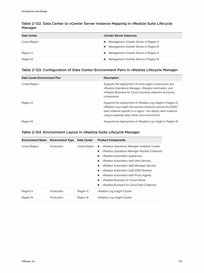
Table 2-122. Data Center to vCenter Server Instance Mapping in vRealize Suite LifecycleManager
Data Center vCenter Server Instances
Cross-Region n Management vCenter Server in Region A
n Management vCenter Server in Region B
Region A n Management vCenter Server in Region A
Region B n Management vCenter Server in Region B
Table 2-123. Configuration of Data Center-Environment Pairs in vRealize Lifecycle Manager
Data Center-Environment Pair Description
Cross-Region Supports the deployment of cross-region components likevRealize Operations Manager, vRealize Automation, andvRealize Business for Cloud including collectors and proxycomponents.
Region A Supports the deployment of vRealize Log Insight in Region A.vRealize Log Insight has several instances across the SDDC,each instance specific to a region. You deploy each instanceusing a separate data center and environment.
Region B Supports the deployment of vRealize Log Insight in Region B.
Table 2-124. Environment Layout in vRealize Suite Lifecycle Manager
Environment Name Environment Type Data Center Product Components
Cross-Region Production Cross-Region n vRealize Operations Manager Analytics Cluster
n vRealize Operations Manager Remote Collectors
n vRealize Automation Appliances
n vRealize Automation IaaS Web Servers
n vRealize Automation IaaS Manager Servers
n vRealize Automation IaaS DEM Workers
n vRealize Automation IaaS Proxy Agents
n vRealize Business for Cloud Server
n vRealize Business for Cloud Data Collectors
Region A Production Region A vRealize Log Insight Cluster
Region B Production Region B vRealize Log Insight Cluster
Architecture and Design
VMware, Inc. 191
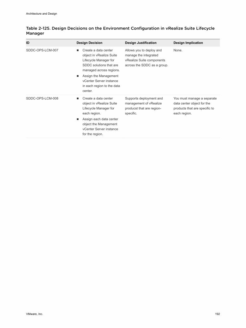
Table 2-125. Design Decisions on the Environment Configuration in vRealize Suite LifecycleManager
ID Design Decision Design Justification Design Implication
SDDC-OPS-LCM-007 n Create a data centerobject in vRealize SuiteLifecycle Manager forSDDC solutions that aremanaged across regions.
n Assign the ManagementvCenter Server instancein each region to the datacenter.
Allows you to deploy andmanage the integratedvRealize Suite componentsacross the SDDC as a group.
None.
SDDC-OPS-LCM-008 n Create a data centerobject in vRealize SuiteLifecycle Manager foreach region.
n Assign each data centerobject the ManagementvCenter Server instancefor the region.
Supports deployment andmanagement of vRealizeproducst that are region-specific.
You must manage a separatedata center object for theproducts that are specific toeach region.
Architecture and Design
VMware, Inc. 192
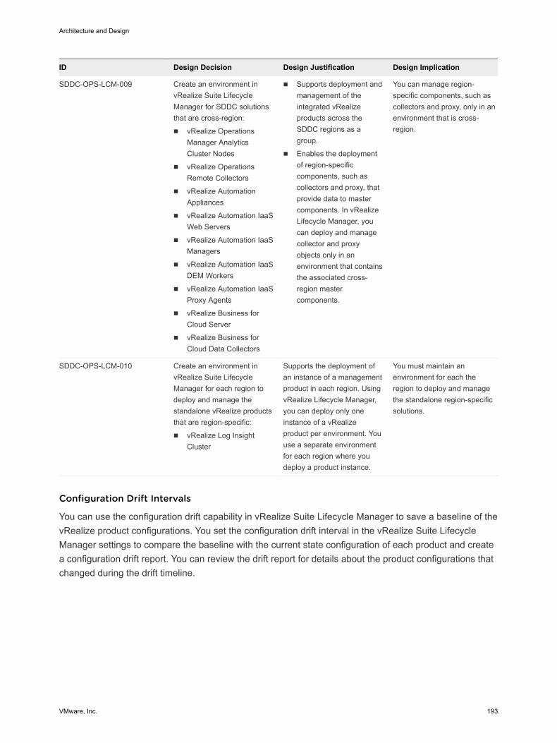
ID Design Decision Design Justification Design Implication
SDDC-OPS-LCM-009 Create an environment invRealize Suite LifecycleManager for SDDC solutionsthat are cross-region:
n vRealize OperationsManager AnalyticsCluster Nodes
n vRealize OperationsRemote Collectors
n vRealize AutomationAppliances
n vRealize Automation IaaSWeb Servers
n vRealize Automation IaaSManagers
n vRealize Automation IaaSDEM Workers
n vRealize Automation IaaSProxy Agents
n vRealize Business forCloud Server
n vRealize Business forCloud Data Collectors
n Supports deployment andmanagement of theintegrated vRealizeproducts across theSDDC regions as agroup.
n Enables the deploymentof region-specificcomponents, such ascollectors and proxy, thatprovide data to mastercomponents. In vRealizeLifecycle Manager, youcan deploy and managecollector and proxyobjects only in anenvironment that containsthe associated cross-region mastercomponents.
You can manage region-specific components, such ascollectors and proxy, only in anenvironment that is cross-region.
SDDC-OPS-LCM-010 Create an environment invRealize Suite LifecycleManager for each region todeploy and manage thestandalone vRealize productsthat are region-specific:
n vRealize Log InsightCluster
Supports the deployment ofan instance of a managementproduct in each region. UsingvRealize Lifecycle Manager,you can deploy only oneinstance of a vRealizeproduct per environment. Youuse a separate environmentfor each region where youdeploy a product instance.
You must maintain anenvironment for each theregion to deploy and managethe standalone region-specificsolutions.
Configuration Drift Intervals
You can use the configuration drift capability in vRealize Suite Lifecycle Manager to save a baseline of thevRealize product configurations. You set the configuration drift interval in the vRealize Suite LifecycleМanager settings to compare the baseline with the current state configuration of each product and createa configuration drift report. You can review the drift report for details about the product configurations thatchanged during the drift timeline.
Architecture and Design
VMware, Inc. 193
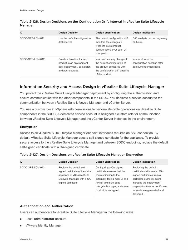
Table 2-126. Design Decisions on the Configuration Drift Interval in vRealize Suite LifecycleManager
ID Design Decision Design Justification Design Implication
SDDC-OPS-LCM-011 Use the default configurationdrift interval.
The default configuration driftmonitors the changes invRealize Suite productconfigurations over each 24-hour period.
Drift analysis occurs only every24 hours.
SDDC-OPS-LCM-012 Create a baseline for eachproduct in an environmentpost-deployment, post-patch,and post-upgrade.
You can view any changes tothe current configuration ofthe product compared withthe configuration drift baselineof the product.
You must save theconfiguration baseline afterdeployment or upgrades.
Information Security and Access Design in vRealize Suite Lifecycle Manager You protect the vRealize Suite Lifecycle Manager deployment by configuring the authentication andsecure communication with the other components in the SDDC. You dedicate a service account to thecommunication between vRealize Suite Lifecycle Manager and vCenter Server.
You use a custom role in vSphere with permissions to perform life cycle operations on vRealize Suitecomponents in the SDDC. A dedicated service account is assigned a custom role for communicationbetween vRealize Suite Lifecycle Manager and the vCenter Server instances in the environment.
Encryption
Access to all vRealize Suite Lifecycle Manager endpoint interfaces requires an SSL connection. Bydefault, vRealize Suite Lifecycle Manager uses a self-signed certificate for the appliance. To providesecure access to the vRealize Suite Lifecycle Manager and between SDDC endpoints, replace the defaultself-signed certificate with a CA-signed certificate.
Table 2-127. Design Decisions on vRealize Suite Lifecycle Manager Encryption
ID Design Decision Design Justification Design Implication
SDDC-OPS-LCM-013 Replace the default self-signed certificate of the virtualappliance of vRealize SuiteLifecycle Manager with a CA-signed certificate.
Configuring a CA-signedcertificate ensures that thecommunication to theexternally facing Web UI andAPI for vRealize SuiteLifecycle Manager, and cross-product, is encrypted.
Replacing the defaultcertificates with trusted CA-signed certificates from acertificate authority mightincrease the deploymentpreparation time as certificatesrequests are generated anddelivered.
Authentication and Authorization
Users can authenticate to vRealize Suite Lifecycle Manager in the following ways:
n Local аdministrator аccount
n VMware Identity Manager
Architecture and Design
VMware, Inc. 194
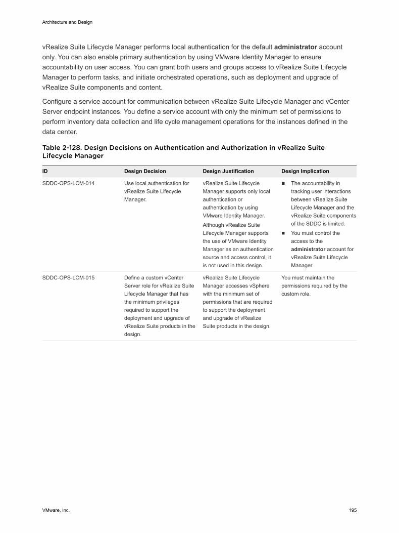
vRealize Suite Lifecycle Manager performs local authentication for the default administrator accountonly. You can also enable primary authentication by using VMware Identity Manager to ensureaccountability on user access. You can grant both users and groups access to vRealize Suite LifecycleManager to perform tasks, and initiate orchestrated operations, such as deployment and upgrade ofvRealize Suite components and content.
Configure a service account for communication between vRealize Suite Lifecycle Manager and vCenterServer endpoint instances. You define a service account with only the minimum set of permissions toperform inventory data collection and life cycle management operations for the instances defined in thedata center.
Table 2-128. Design Decisions on Authentication and Authorization in vRealize SuiteLifecycle Manager
ID Design Decision Design Justification Design Implication
SDDC-OPS-LCM-014 Use local authentication forvRealize Suite LifecycleManager.
vRealize Suite LifecycleManager supports only localauthentication orauthentication by usingVMware Identity Manager.
Although vRealize SuiteLifecycle Manager supportsthe use of VMware IdentityManager as an authenticationsource and access control, itis not used in this design.
n The accountability intracking user interactionsbetween vRealize SuiteLifecycle Manager and thevRealize Suite componentsof the SDDC is limited.
n You must control theaccess to theadministrator account forvRealize Suite LifecycleManager.
SDDC-OPS-LCM-015 Define a custom vCenterServer role for vRealize SuiteLifecycle Manager that hasthe minimum privilegesrequired to support thedeployment and upgrade ofvRealize Suite products in thedesign.
vRealize Suite LifecycleManager accesses vSpherewith the minimum set ofpermissions that are requiredto support the deploymentand upgrade of vRealizeSuite products in the design.
You must maintain thepermissions required by thecustom role.
Architecture and Design
VMware, Inc. 195
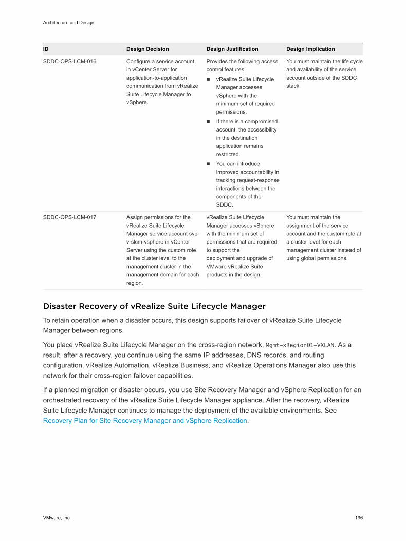
ID Design Decision Design Justification Design Implication
SDDC-OPS-LCM-016 Configure a service accountin vCenter Server forapplication-to-applicationcommunication from vRealizeSuite Lifecycle Manager tovSphere.
Provides the following accesscontrol features:
n vRealize Suite LifecycleManager accessesvSphere with theminimum set of requiredpermissions.
n If there is a compromisedaccount, the accessibilityin the destinationapplication remainsrestricted.
n You can introduceimproved accountability intracking request-responseinteractions between thecomponents of theSDDC.
You must maintain the life cycleand availability of the serviceaccount outside of the SDDCstack.
SDDC-OPS-LCM-017 Assign permissions for thevRealize Suite LifecycleManager service account svc-vrslcm-vsphere in vCenterServer using the custom roleat the cluster level to themanagement cluster in themanagement domain for eachregion.
vRealize Suite LifecycleManager accesses vSpherewith the minimum set ofpermissions that are requiredto support thedeployment and upgrade ofVMware vRealize Suiteproducts in the design.
You must maintain theassignment of the serviceaccount and the custom role ata cluster level for eachmanagement cluster instead ofusing global permissions.
Disaster Recovery of vRealize Suite Lifecycle Manager To retain operation when a disaster occurs, this design supports failover of vRealize Suite LifecycleManager between regions.
You place vRealize Suite Lifecycle Manager on the cross-region network, Mgmt-xRegion01-VXLAN. As aresult, after a recovery, you continue using the same IP addresses, DNS records, and routingconfiguration. vRealize Automation, vRealize Business, and vRealize Operations Manager also use thisnetwork for their cross-region failover capabilities.
If a planned migration or disaster occurs, you use Site Recovery Manager and vSphere Replication for anorchestrated recovery of the vRealize Suite Lifecycle Manager appliance. After the recovery, vRealizeSuite Lifecycle Manager continues to manage the deployment of the available environments. SeeRecovery Plan for Site Recovery Manager and vSphere Replication.
Architecture and Design
VMware, Inc. 196
vRealize Operations Manager Design The deployment of vRealize Operations Manager is a single instance of a 3-node analytics cluster that isdeployed in the protected region of the SDDC, and a two-node remote collector group in each region. Thecomponents run on the management cluster in each region.
n Logical and Physical Design of vRealize Operations Manager
vRealize Operations Manager communicates with all management components in all regions of theSDDC to collect metrics which are presented through a number of dashboards and views.
n Node Configuration of vRealize Operations Manager
The analytics cluster of the vRealize Operations Manager deployment contains the nodes thatanalyze and store data from the monitored components. You deploy a configuration of the analyticscluster that satisfies the requirements for monitoring the number of virtual machines in the designobjectives of this validated design.
n Networking Design of vRealize Operations Manager
You provide isolation of the vRealize Operations Manager nodes by placing them in several networksegments. This networking design also supports public access to the analytics cluster nodes.
n Information Security and Access Control in vRealize Operations Manager
You protect the vRealize Operations Manager deployment by providing centralized role-basedauthentication and secure communication with the other components in the SDDC. You dedicate aset of service accounts to the communication between vRealize Operations Manager and themanagement solutions in the data center.
n Monitoring and Alerting in vRealize Operations Manager
You use vRealize Operations Manager to monitor the state of the SDDC management componentsin the SDDC by using dashboards. You can use the self-monitoring capability of vRealize OperationsManager to receive alerts about issues that are related to its operational state.
n Management Packs in vRealize Operations Manager
The SDDC contains VMware products for network, storage, and cloud management. You canmonitor and perform diagnostics on all of them in vRealize Operations Manager by usingmanagement packs.
n Disaster Recovery of vRealize Operations Manager
To preserve the monitoring functionality when a disaster occurs, the design of vRealize OperationsManager supports failing over a subset of the components between regions. Disaster recoverycovers only the analytics cluster components, including the master, replica, and data nodes. Theregion-specific remote collector nodes remain in the affected region.
Logical and Physical Design of vRealize Operations Manager vRealize Operations Manager communicates with all management components in all regions of theSDDC to collect metrics which are presented through a number of dashboards and views.
Architecture and Design
VMware, Inc. 197
Logical Design
In a multi-region SDDC, you deploy a vRealize Operations Manager configuration that consists of thefollowing entities.
n A 3-node medium-size vRealize Operations Manager analytics cluster that is highly available (HA).This topology provides high availability, scale-out capacity up to sixteen nodes, and failover.
n A group of two remote collector nodes in each region. The remote collectors communicate directlywith the data nodes in the vRealize Operations Manager analytics cluster. Use two remote collectorsin each region for load balancing and fault tolerance.
Each region contains its own pair of remote collectors whose role is to ease scalability by performing thedata collection from the applications that are not subject to failover and periodically sending collected datato the analytics cluster. You fail over the analytics cluster only, because the analytics cluster is theconstruct that analyzes and stores monitoring data.
This configuration supports failover of the analytics cluster by using Site Recovery Manager. In the eventof a disaster, Site Recovery Manager migrates the analytics cluster nodes to the failover region.
Architecture and Design
VMware, Inc. 198
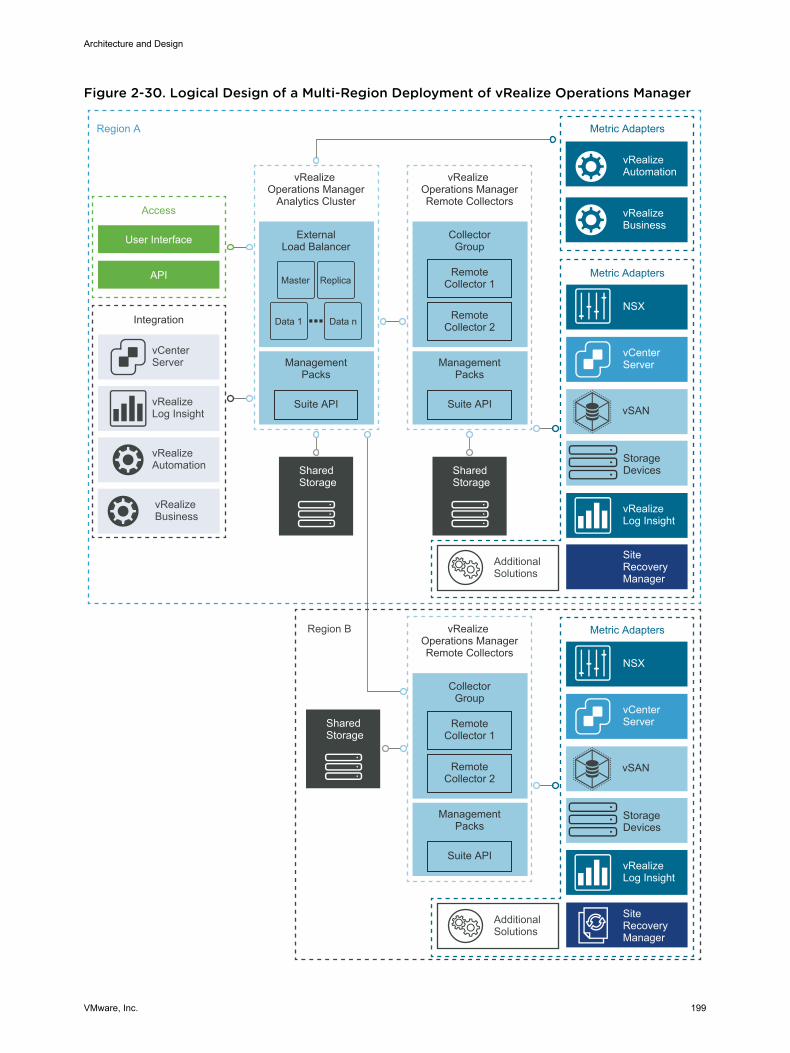
Figure 2-30. Logical Design of a Multi-Region Deployment of vRealize Operations Manager
Metric AdaptersRegion A
Region B
vRealize Operations Manager
Analytics Cluster
Integration
ExternalLoad Balancer
vCenter Server
Access
User Interface
API
vRealizeLog Insight
vRealizeAutomation
Metric Adapters
vCenter Server
NSX
vRealizeLog Insight
AdditionalSolutions
vRealizeBusiness
vRealizeAutomation
ManagementPacks
Suite API
Shared Storage
vRealize Operations ManagerRemote Collectors
CollectorGroup
ManagementPacks
Suite API
Remote Collector 2
Remote Collector 1
Shared Storage
Metric Adapters
vCenter Server
NSX
vRealizeLog Insight
vRealize Operations ManagerRemote Collectors
CollectorGroup
ManagementPacks
Suite API
Remote Collector 2
Remote Collector 1
Shared Storage
StorageDevices
vSAN
StorageDevices
vSAN
Master Replica
Data 1 Data n
vRealizeBusiness
SiteRecoveryManager
AdditionalSolutions
SiteRecoveryManager
Architecture and Design
VMware, Inc. 199
Physical Design
The vRealize Operations Manager nodes run on the management cluster in each region of SDDC. Forinformation about the types of clusters, see Workload Domain Architecture .
Data Sources
vRealize Operations Manager collects data from the following virtual infrastructure and cloudmanagement components.
n Virtual Infrastructure
n Platform Services Controller instances
n vCenter Server instances
n ESXi hosts
n NSX Manager instances
n NSX Controller instances
n NSX Edge instances
n Shared storage
n vRealize Automation
n vRealize Automation Appliance
n vRealize IaaS Web Server
n vRealize IaaS Management Server
n vRealize IaaS DEM
n vRealize IaaS Proxy Agents
n vRealize Orchestrator (embedded in the vRealize Automation Appliance)
n Microsoft SQL Server
n vRealize Business for Cloud
n vRealize Business Server
n vRealize Business Data Collector instances
n vRealize Log Insight
n Site Recovery Manager
Node Configuration of vRealize Operations Manager The analytics cluster of the vRealize Operations Manager deployment contains the nodes that analyzeand store data from the monitored components. You deploy a configuration of the analytics cluster thatsatisfies the requirements for monitoring the number of virtual machines in the design objectives of thisvalidated design.
Architecture and Design
VMware, Inc. 200
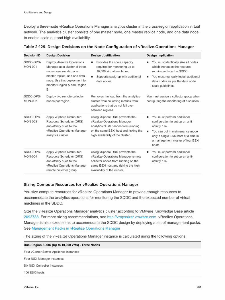
Deploy a three-node vRealize Operations Manager analytics cluster in the cross-region application virtualnetwork. The analytics cluster consists of one master node, one master replica node, and one data nodeto enable scale out and high availability.
Table 2-129. Design Decisions on the Node Configuration of vRealize Operations Manager
Decision ID Design Decision Design Justification Design Implication
SDDC-OPS-MON-001
Deploy vRealize OperationsManager as a cluster of threenodes: one master, onemaster replica, and one datanode. Use this deployment tomonitor Region A and RegionB.
n Provides the scale capacityrequired for monitoring up to10,000 virtual machines.
n Supports scale-up with additionaldata nodes.
n You must identically size all nodeswhich increases the resourcerequirements in the SDDC.
n You must manually install additionaldata nodes as per the data nodescale guidelines.
SDDC-OPS-MON-002
Deploy two remote collectornodes per region.
Removes the load from the analyticscluster from collecting metrics fromapplications that do not fail overbetween regions.
You must assign a collector group whenconfiguring the monitoring of a solution.
SDDC-OPS-MON-003
Apply vSphere DistributedResource Scheduler (DRS)anti-affinity rules to thevRealize Operations Manageranalytics cluster.
Using vSphere DRS prevents thevRealize Operations Manageranalytics cluster nodes from runningon the same ESXi host and risking thehigh availability of the cluster.
n You must perform additionalconfiguration to set up an anti-affinity rule.
n You can put in maintenance modeonly a single ESXi host at a time ina management cluster of four ESXihosts.
SDDC-OPS-MON-004
Apply vSphere DistributedResource Scheduler (DRS)anti-affinity rules to thevRealize Operations Managerremote collector group.
Using vSphere DRS prevents thevRealize Operations Manager remotecollector nodes from running on thesame ESXi host and risking the highavailability of the cluster.
n You must perform additionalconfiguration to set up an anti-affinity rule.
Sizing Compute Resources for vRealize Operations Manager
You size compute resources for vRealize Operations Manager to provide enough resources toaccommodate the analytics operations for monitoring the SDDC and the expected number of virtualmachines in the SDDC.
Size the vRealize Operations Manager analytics cluster according to VMware Knowledge Base article2093783. For more sizing recommendations, see http://vropssizer.vmware.com. vRealize OperationsManager is also sized so as to accommodate the SDDC design by deploying a set of management packs.See Management Packs in vRealize Operations Manager
The sizing of the vRealize Operations Manager instance is calculated using the following options:
Dual-Region SDDC (Up to 10,000 VMs) - Three Nodes
Four vCenter Server Appliance instances
Four NSX Manager instances
Six NSX Controller instances
100 ESXi hosts
Architecture and Design
VMware, Inc. 201

Dual-Region SDDC (Up to 10,000 VMs) - Three Nodes
Four vSAN datastores
10,000 virtual machines
Sizing Compute Resources for the Analytics Cluster Nodes
Deploying three medium-size nodes satisfies the requirement for retention and for monitoring theexpected number of objects and metrics for-dual-region environments with up to 10,000 virtual machines.As the environment expands beyond 10,000 virtual machines or 12,500 total objects, deploy additionaldata notes to accommodate the higher expected number of objects and metrics. For detailed sizing andscaling guidance, you can use the VMware vRealize Operations Manager. See http://vropssizer.vmware.com.
Consider deploying additional vRealize Operations Manager data nodes only if more ESXi hosts areadded to the managementcluster to guarantee that the vSphere cluster has enough capacity to hostthese additional nodes without violating the vSphere DRS anti-affinity rules.
Table 2-130. Resources for a Medium-Size vRealize Operations Manager Appliance
Attribute Specification
Appliance size Medium
vCPU 8
Memory 32 GB
Architecture and Design
VMware, Inc. 202
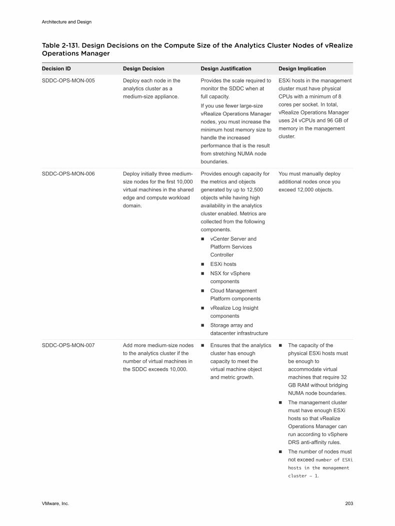
Table 2-131. Design Decisions on the Compute Size of the Analytics Cluster Nodes of vRealizeOperations Manager
Decision ID Design Decision Design Justification Design Implication
SDDC-OPS-MON-005 Deploy each node in theanalytics cluster as amedium-size appliance.
Provides the scale required tomonitor the SDDC when atfull capacity.
If you use fewer large-sizevRealize Operations Managernodes, you must increase theminimum host memory size tohandle the increasedperformance that is the resultfrom stretching NUMA nodeboundaries.
ESXi hosts in the managementcluster must have physicalCPUs with a minimum of 8cores per socket. In total,vRealize Operations Manageruses 24 vCPUs and 96 GB ofmemory in the managementcluster.
SDDC-OPS-MON-006 Deploy initially three medium-size nodes for the first 10,000virtual machines in the sharededge and compute workloaddomain.
Provides enough capacity forthe metrics and objectsgenerated by up to 12,500objects while having highavailability in the analyticscluster enabled. Metrics arecollected from the followingcomponents.
n vCenter Server andPlatform ServicesController
n ESXi hosts
n NSX for vSpherecomponents
n Cloud ManagementPlatform components
n vRealize Log Insightcomponents
n Storage array anddatacenter infrastructure
You must manually deployadditional nodes once youexceed 12,000 objects.
SDDC-OPS-MON-007 Add more medium-size nodesto the analytics cluster if thenumber of virtual machines inthe SDDC exceeds 10,000.
n Ensures that the analyticscluster has enoughcapacity to meet thevirtual machine objectand metric growth.
n The capacity of thephysical ESXi hosts mustbe enough toaccommodate virtualmachines that require 32GB RAM without bridgingNUMA node boundaries.
n The management clustermust have enough ESXihosts so that vRealizeOperations Manager canrun according to vSphereDRS anti-affinity rules.
n The number of nodes mustnot exceed number of ESXihosts in the management
cluster - 1.
Architecture and Design
VMware, Inc. 203
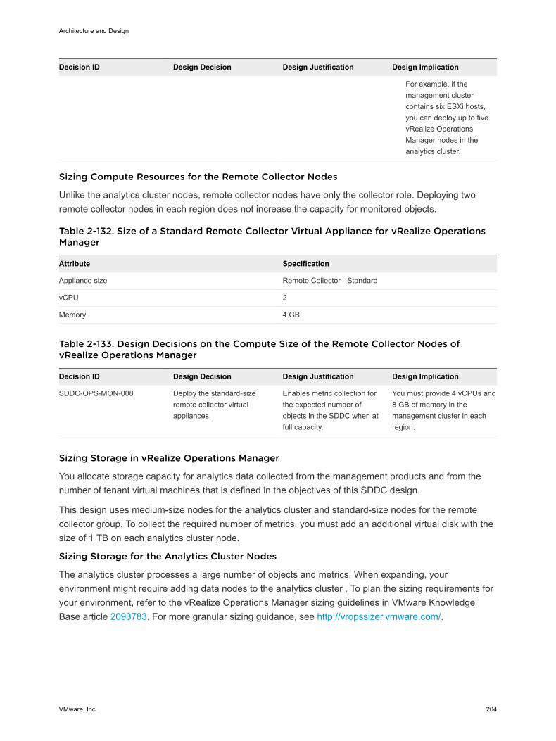
Decision ID Design Decision Design Justification Design Implication
For example, if themanagement clustercontains six ESXi hosts,you can deploy up to fivevRealize OperationsManager nodes in theanalytics cluster.
Sizing Compute Resources for the Remote Collector Nodes
Unlike the analytics cluster nodes, remote collector nodes have only the collector role. Deploying tworemote collector nodes in each region does not increase the capacity for monitored objects.
Table 2-132. Size of a Standard Remote Collector Virtual Appliance for vRealize OperationsManager
Attribute Specification
Appliance size Remote Collector - Standard
vCPU 2
Memory 4 GB
Table 2-133. Design Decisions on the Compute Size of the Remote Collector Nodes ofvRealize Operations Manager
Decision ID Design Decision Design Justification Design Implication
SDDC-OPS-MON-008 Deploy the standard-sizeremote collector virtualappliances.
Enables metric collection forthe expected number ofobjects in the SDDC when atfull capacity.
You must provide 4 vCPUs and8 GB of memory in themanagement cluster in eachregion.
Sizing Storage in vRealize Operations Manager
You allocate storage capacity for analytics data collected from the management products and from thenumber of tenant virtual machines that is defined in the objectives of this SDDC design.
This design uses medium-size nodes for the analytics cluster and standard-size nodes for the remotecollector group. To collect the required number of metrics, you must add an additional virtual disk with thesize of 1 TB on each analytics cluster node.
Sizing Storage for the Analytics Cluster Nodes
The analytics cluster processes a large number of objects and metrics. When expanding, yourenvironment might require adding data nodes to the analytics cluster . To plan the sizing requirements foryour environment, refer to the vRealize Operations Manager sizing guidelines in VMware KnowledgeBase article 2093783. For more granular sizing guidance, see http://vropssizer.vmware.com/.
Architecture and Design
VMware, Inc. 204
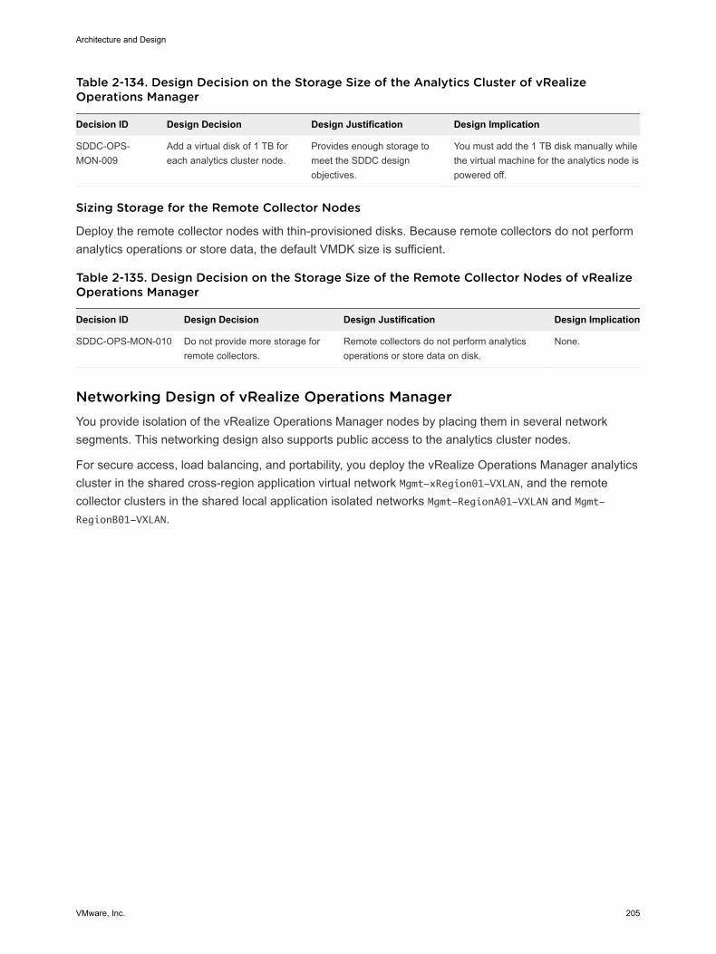
Table 2-134. Design Decision on the Storage Size of the Analytics Cluster of vRealizeOperations Manager
Decision ID Design Decision Design Justification Design Implication
SDDC-OPS-MON-009
Add a virtual disk of 1 TB foreach analytics cluster node.
Provides enough storage tomeet the SDDC designobjectives.
You must add the 1 TB disk manually whilethe virtual machine for the analytics node ispowered off.
Sizing Storage for the Remote Collector Nodes
Deploy the remote collector nodes with thin-provisioned disks. Because remote collectors do not performanalytics operations or store data, the default VMDK size is sufficient.
Table 2-135. Design Decision on the Storage Size of the Remote Collector Nodes of vRealizeOperations Manager
Decision ID Design Decision Design Justification Design Implication
SDDC-OPS-MON-010 Do not provide more storage forremote collectors.
Remote collectors do not perform analyticsoperations or store data on disk.
None.
Networking Design of vRealize Operations Manager You provide isolation of the vRealize Operations Manager nodes by placing them in several networksegments. This networking design also supports public access to the analytics cluster nodes.
For secure access, load balancing, and portability, you deploy the vRealize Operations Manager analyticscluster in the shared cross-region application virtual network Mgmt-xRegion01-VXLAN, and the remotecollector clusters in the shared local application isolated networks Mgmt-RegionA01-VXLAN and Mgmt-RegionB01-VXLAN.
Architecture and Design
VMware, Inc. 205
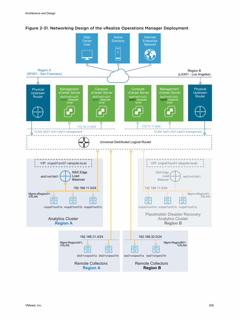
Figure 2-31. Networking Design of the vRealize Operations Manager Deployment
APP
OSAPP
OSAPP
OSAPP
OS
APP
OSAPP
OSAPP
OSAPP
OSAPP
OSAPP
OS
Universal Distributed Logical Router
DataCenterUser
ActiveDirectory
Internet/EnterpriseNetwork
Region A(SF001 - San Francisco)
Management vCenter Serverlax01m01vc01.lax01.rainpole.
local
Compute vCenter Serverlax01w01vc01.lax01.rainpole.
local
sfo01vropsc01a sfo01vropsc01b
Mgmt-RegionA01-VXLAN
VLAN: sfo01-m01-vds01-management
172.16.11.0/24
VLAN: lax01-m01-vds01-management.
172.17.11.0/24
Management vCenter Server
sfo01m01vc01.sfo01.rainpole.
local
Compute vCenter Serversfo01w01vc01.sfo01.rainpole.
local
PhysicalUpstream
Router
vrops01svr01a vrops01svr01b vrops01svr01c
192.168.11.0/24
Mgmt-xRegion01-VXLAN
VIP: vrops01svr01.rainpole.local
Analytics Cluster Region A
192.168.31.0/24
Remote Collectors Region A
Region B(LAX01 - Los Angeles)
PhysicalUpstream
Router
lax01vropsc01a lax01vropsc01b
Mgmt-RegionB01-VXLAN
192.168.32.0/24
Remote Collectors
Region B
vrops01svr01a vrops01svr01b vrops01svr01c
192.168.11.0/24
VIP: vrops01svr01.rainpole.local
Placeholder Disaster RecoveryAnalytics Cluster
Region B
sfo01m01lb01 lax01m01lb01
Mgmt-xRegion01-VXLAN
NSX EdgeLoad
Balancer
NSX EdgeLoadBalancer
Architecture and Design
VMware, Inc. 206
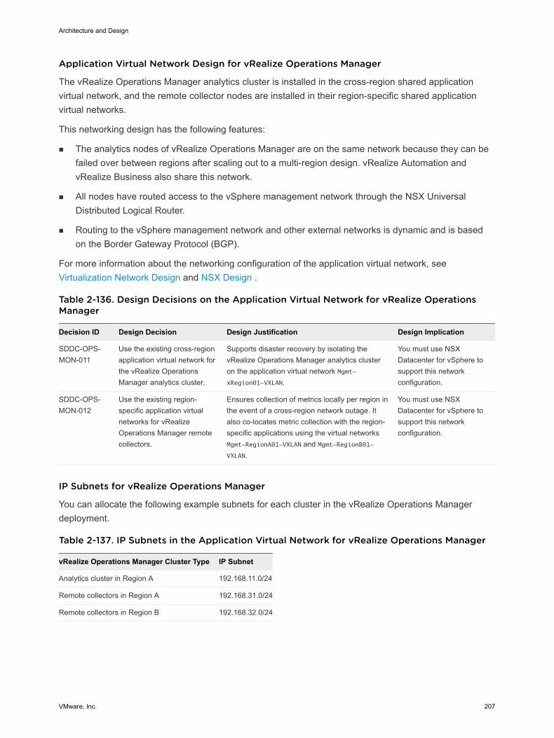
Application Virtual Network Design for vRealize Operations Manager
The vRealize Operations Manager analytics cluster is installed in the cross-region shared applicationvirtual network, and the remote collector nodes are installed in their region-specific shared applicationvirtual networks.
This networking design has the following features:
n The analytics nodes of vRealize Operations Manager are on the same network because they can befailed over between regions after scaling out to a multi-region design. vRealize Automation andvRealize Business also share this network.
n All nodes have routed access to the vSphere management network through the NSX UniversalDistributed Logical Router.
n Routing to the vSphere management network and other external networks is dynamic and is basedon the Border Gateway Protocol (BGP).
For more information about the networking configuration of the application virtual network, seeVirtualization Network Design and NSX Design .
Table 2-136. Design Decisions on the Application Virtual Network for vRealize OperationsManager
Decision ID Design Decision Design Justification Design Implication
SDDC-OPS-MON-011
Use the existing cross-regionapplication virtual network forthe vRealize OperationsManager analytics cluster.
Supports disaster recovery by isolating thevRealize Operations Manager analytics clusteron the application virtual network Mgmt-xRegion01-VXLAN.
You must use NSXDatacenter for vSphere tosupport this networkconfiguration.
SDDC-OPS-MON-012
Use the existing region-specific application virtualnetworks for vRealizeOperations Manager remotecollectors.
Ensures collection of metrics locally per region inthe event of a cross-region network outage. Italso co-locates metric collection with the region-specific applications using the virtual networksMgmt-RegionA01-VXLAN and Mgmt-RegionB01-VXLAN.
You must use NSXDatacenter for vSphere tosupport this networkconfiguration.
IP Subnets for vRealize Operations Manager
You can allocate the following example subnets for each cluster in the vRealize Operations Managerdeployment.
Table 2-137. IP Subnets in the Application Virtual Network for vRealize Operations Manager
vRealize Operations Manager Cluster Type IP Subnet
Analytics cluster in Region A 192.168.11.0/24
Remote collectors in Region A 192.168.31.0/24
Remote collectors in Region B 192.168.32.0/24
Architecture and Design
VMware, Inc. 207
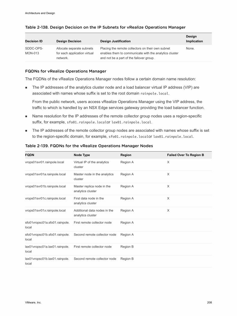
Table 2-138. Design Decision on the IP Subnets for vRealize Operations Manager
Decision ID Design Decision Design JustificationDesignImplication
SDDC-OPS-MON-013
Allocate separate subnetsfor each application virtualnetwork.
Placing the remote collectors on their own subnetenables them to communicate with the analytics clusterand not be a part of the failover group.
None.
FQDNs for vRealize Operations Manager
The FQDNs of the vRealize Operations Manager nodes follow a certain domain name resolution:
n The IP addresses of the analytics cluster node and a load balancer virtual IP address (VIP) areassociated with names whose suffix is set to the root domain rainpole.local.
From the public network, users access vRealize Operations Manager using the VIP address, thetraffic to which is handled by an NSX Edge services gateway providing the load balancer function.
n Name resolution for the IP addresses of the remote collector group nodes uses a region-specificsuffix, for example, sfo01.rainpole.localor lax01.rainpole.local.
n The IP addresses of the remote collector group nodes are associated with names whose suffix is setto the region-specific domain, for example, sfo01.rainpole.localor lax01.rainpole.local.
Table 2-139. FQDNs for the vRealize Operations Manager Nodes
FQDN Node Type Region Failed Over To Region B
vrops01svr01.rainpole.local Virtual IP of the analyticscluster
Region A X
vrops01svr01a.rainpole.local Master node in the analyticscluster
Region A X
vrops01svr01b.rainpole.local Master replica node in theanalytics cluster
Region A X
vrops01svr01c.rainpole.local First data node in theanalytics cluster
Region A X
vrops01svr01x.rainpole.local Additional data nodes in theanalytics cluster
Region A X
sfo01vropsc01a.sfo01.rainpole.local
First remote collector node Region A
sfo01vropsc01b.sfo01.rainpole.local
Second remote collector node Region A
lax01vropsc01a.lax01.rainpole.local
First remote collector node Region B
lax01vropsc01b.lax01.rainpole.local
Second remote collector node Region B
Architecture and Design
VMware, Inc. 208
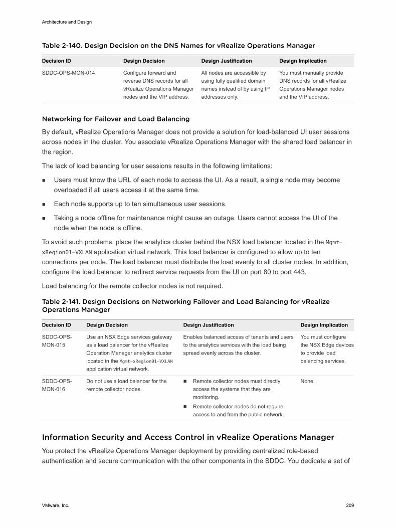
Table 2-140. Design Decision on the DNS Names for vRealize Operations Manager
Decision ID Design Decision Design Justification Design Implication
SDDC-OPS-MON-014 Configure forward andreverse DNS records for allvRealize Operations Managernodes and the VIP address.
All nodes are accessible byusing fully qualified domainnames instead of by using IPaddresses only.
You must manually provideDNS records for all vRealizeOperations Manager nodesand the VIP address.
Networking for Failover and Load Balancing
By default, vRealize Operations Manager does not provide a solution for load-balanced UI user sessionsacross nodes in the cluster. You associate vRealize Operations Manager with the shared load balancer inthe region.
The lack of load balancing for user sessions results in the following limitations:
n Users must know the URL of each node to access the UI. As a result, a single node may becomeoverloaded if all users access it at the same time.
n Each node supports up to ten simultaneous user sessions.
n Taking a node offline for maintenance might cause an outage. Users cannot access the UI of thenode when the node is offline.
To avoid such problems, place the analytics cluster behind the NSX load balancer located in the Mgmt-xRegion01-VXLAN application virtual network. This load balancer is configured to allow up to tenconnections per node. The load balancer must distribute the load evenly to all cluster nodes. In addition,configure the load balancer to redirect service requests from the UI on port 80 to port 443.
Load balancing for the remote collector nodes is not required.
Table 2-141. Design Decisions on Networking Failover and Load Balancing for vRealizeOperations Manager
Decision ID Design Decision Design Justification Design Implication
SDDC-OPS-MON-015
Use an NSX Edge services gatewayas a load balancer for the vRealizeOperation Manager analytics clusterlocated in the Mgmt-xRegion01-VXLANapplication virtual network.
Enables balanced access of tenants and usersto the analytics services with the load beingspread evenly across the cluster.
You must configurethe NSX Edge devicesto provide loadbalancing services.
SDDC-OPS-MON-016
Do not use a load balancer for theremote collector nodes.
n Remote collector nodes must directlyaccess the systems that they aremonitoring.
n Remote collector nodes do not requireaccess to and from the public network.
None.
Information Security and Access Control in vRealize Operations Manager You protect the vRealize Operations Manager deployment by providing centralized role-basedauthentication and secure communication with the other components in the SDDC. You dedicate a set of
Architecture and Design
VMware, Inc. 209
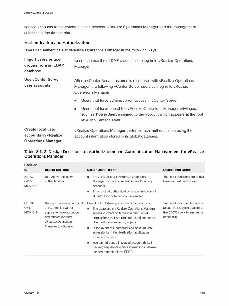
service accounts to the communication between vRealize Operations Manager and the managementsolutions in the data center.
Authentication and Authorization
Users can authenticate to vRealize Operations Manager in the following ways:
Import users or usergroups from an LDAPdatabase
Users can use their LDAP credentials to log in to vRealize OperationsManager.
Use vCenter Serveruser accounts
After a vCenter Server instance is registered with vRealize OperationsManager, the following vCenter Server users can log in to vRealizeOperations Manager:
n Users that have administration access in vCenter Server.
n Users that have one of the vRealize Operations Manager privileges,such as PowerUser, assigned to the account which appears at the rootlevel in vCenter Server.
Create local useraccounts in vRealizeOperations Manager
vRealize Operations Manager performs local authentication using theaccount information stored in its global database.
Table 2-142. Design Decisions on Authorization and Authentication Management for vRealizeOperations Manager
DecisionID Design Decision Design Justification Design Implication
SDDC-OPS-MON-017
Use Active Directoryauthentication.
n Provides access to vRealize OperationsManager by using standard Active Directoryaccounts.
n Ensures that authentication is available even ifvCenter Server becomes unavailable.
You must configure the ActiveDirectory authentication.
SDDC-OPS-MON-018
Configure a service accountin vCenter Server forapplication-to-applicationcommunication fromvRealize OperationsManager to vSphere.
Provides the following access control features:
n The adapters in vRealize Operations Manageraccess vSphere with the minimum set ofpermissions that are required to collect metricsabout vSphere inventory objects.
n In the event of a compromised account, theaccessibility in the destination applicationremains restricted.
n You can introduce improved accountability intracking request-response interactions betweenthe components of the SDDC.
You must maintain the serviceaccount's life cycle outside ofthe SDDC stack to ensure itsavailability.
Architecture and Design
VMware, Inc. 210
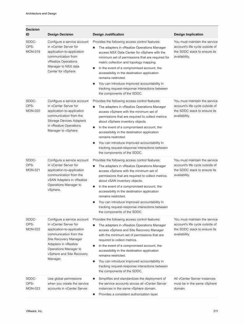
DecisionID Design Decision Design Justification Design Implication
SDDC-OPS-MON-019
Configure a service accountin vCenter Server forapplication-to-applicationcommunication fromvRealize OperationsManager to NSX dataCenter for vSphere
Provides the following access control features:
n The adapters in vRealize Operations Manageraccess NSX Data Center for vSphere with theminimum set of permissions that are required formetric collection and topology mapping.
n In the event of a compromised account, theaccessibility in the destination applicationremains restricted.
n You can introduce improved accountability intracking request-response interactions betweenthe components of the SDDC.
You must maintain the serviceaccount's life cycle outside ofthe SDDC stack to ensure itsavailability.
SDDC-OPS-MON-020
Configure a service accountin vCenter Server forapplication-to-applicationcommunication from theStorage Devices Adaptersin vRealize OperationsManager to vSphere.
Provides the following access control features:
n The adapters in vRealize Operations Manageraccess vSphere with the minimum set ofpermissions that are required to collect metricsabout vSphere inventory objects.
n In the event of a compromised account, theaccessibility in the destination applicationremains restricted.
n You can introduce improved accountability intracking request-response interactions betweenthe components of the SDDC.
You must maintain the serviceaccount's life cycle outside ofthe SDDC stack to ensure itsavailability.
SDDC-OPS-MON-021
Configure a service accountin vCenter Server forapplication-to-applicationcommunication from thevSAN Adapters in vRealizeOperations Manager tovSphere.
Provides the following access control features:
n The adapters in vRealize Operations Manageraccess vSphere with the minimum set ofpermissions that are required to collect metricsabout vSAN inventory objects.
n In the event of a compromised account, theaccessibility in the destination applicationremains restricted.
n You can introduce improved accountability intracking request-response interactions betweenthe components of the SDDC.
You must maintain the serviceaccount's life cycle outside ofthe SDDC stack to ensure itsavailability.
SDDC-OPS-MON-022
Configure a service accountin vCenter Server forapplication-to-applicationcommunication from theSite Recovery ManagerAdapters in vRealizeOperations Manager tovSphere and Site RecoveryManager.
Provides the following access control features:
n The adapters in vRealize Operations Manageraccess vSphere and Site Recovery Managerwith the minimum set of permissions that arerequired to collect metrics.
n In the event of a compromised account, theaccessibility in the destination applicationremains restricted.
n You can introduce improved accountability intracking request-response interactions betweenthe components of the SDDC.
You must maintain the serviceaccount's life cycle outside ofthe SDDC stack to ensure itsavailability.
SDDC-OPS-MON-023
Use global permissionswhen you create the serviceaccounts in vCenter Server.
n Simplifies and standardizes the deployment ofthe service accounts across all vCenter Serverinstances in the same vSphere domain.
n Provides a consistent authorization layer.
All vCenter Server instancesmust be in the same vSpheredomain.
Architecture and Design
VMware, Inc. 211
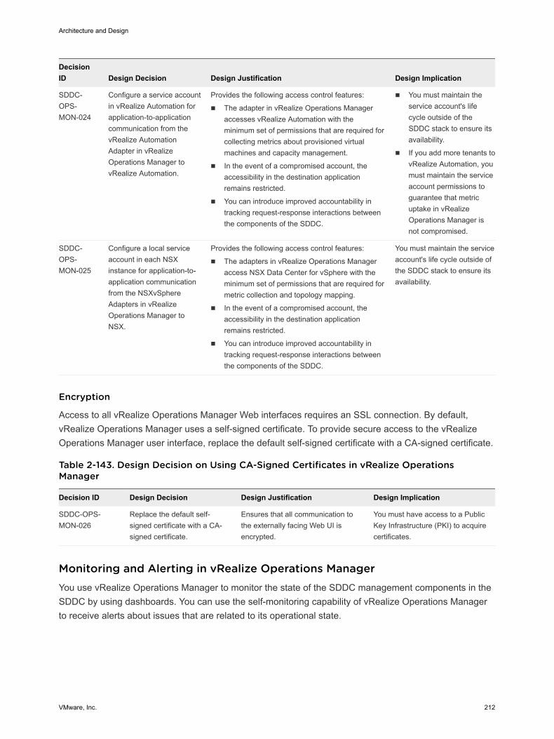
DecisionID Design Decision Design Justification Design Implication
SDDC-OPS-MON-024
Configure a service accountin vRealize Automation forapplication-to-applicationcommunication from thevRealize AutomationAdapter in vRealizeOperations Manager tovRealize Automation.
Provides the following access control features:
n The adapter in vRealize Operations Manageraccesses vRealize Automation with theminimum set of permissions that are required forcollecting metrics about provisioned virtualmachines and capacity management.
n In the event of a compromised account, theaccessibility in the destination applicationremains restricted.
n You can introduce improved accountability intracking request-response interactions betweenthe components of the SDDC.
n You must maintain theservice account's lifecycle outside of theSDDC stack to ensure itsavailability.
n If you add more tenants tovRealize Automation, youmust maintain the serviceaccount permissions toguarantee that metricuptake in vRealizeOperations Manager isnot compromised.
SDDC-OPS-MON-025
Configure a local serviceaccount in each NSXinstance for application-to-application communicationfrom the NSXvSphereAdapters in vRealizeOperations Manager toNSX.
Provides the following access control features:
n The adapters in vRealize Operations Manageraccess NSX Data Center for vSphere with theminimum set of permissions that are required formetric collection and topology mapping.
n In the event of a compromised account, theaccessibility in the destination applicationremains restricted.
n You can introduce improved accountability intracking request-response interactions betweenthe components of the SDDC.
You must maintain the serviceaccount's life cycle outside ofthe SDDC stack to ensure itsavailability.
Encryption
Access to all vRealize Operations Manager Web interfaces requires an SSL connection. By default,vRealize Operations Manager uses a self-signed certificate. To provide secure access to the vRealizeOperations Manager user interface, replace the default self-signed certificate with a CA-signed certificate.
Table 2-143. Design Decision on Using CA-Signed Certificates in vRealize OperationsManager
Decision ID Design Decision Design Justification Design Implication
SDDC-OPS-MON-026
Replace the default self-signed certificate with a CA-signed certificate.
Ensures that all communication tothe externally facing Web UI isencrypted.
You must have access to a PublicKey Infrastructure (PKI) to acquirecertificates.
Monitoring and Alerting in vRealize Operations Manager You use vRealize Operations Manager to monitor the state of the SDDC management components in theSDDC by using dashboards. You can use the self-monitoring capability of vRealize Operations Managerto receive alerts about issues that are related to its operational state.
Architecture and Design
VMware, Inc. 212
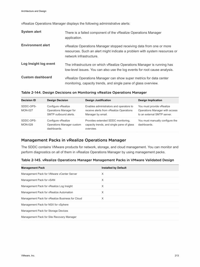
vRealize Operations Manager displays the following administrative alerts:
System alert There is a failed component of the vRealize Operations Managerapplication.
Environment alert vRealize Operations Manager stopped receiving data from one or moreresources. Such an alert might indicate a problem with system resources ornetwork infrastructure.
Log Insight log event The infrastructure on which vRealize Operations Manager is running haslow-level issues. You can also use the log events for root cause analysis.
Custom dashboard vRealize Operations Manager can show super metrics for data centermonitoring, capacity trends, and single pane of glass overview.
Table 2-144. Design Decisions on Monitoring vRealize Operations Manager
Decision ID Design Decision Design Justification Design Implication
SDDC-OPS-MON-027
Configure vRealizeOperations Manager forSMTP outbound alerts.
Enables administrators and operators toreceive alerts from vRealize OperationsManager by email.
You must provide vRealizeOperations Manager with accessto an external SMTP server.
SDDC-OPS-MON-028
Configure vRealizeOperations Manager customdashboards.
Provides extended SDDC monitoring,capacity trends, and single pane of glassoverview.
You must manually configure thedashboards.
Management Packs in vRealize Operations Manager The SDDC contains VMware products for network, storage, and cloud management. You can monitor andperform diagnostics on all of them in vRealize Operations Manager by using management packs.
Table 2-145. vRealize Operations Manager Management Packs in VMware Validated Design
Management Pack Installed by Default
Management Pack for VMware vCenter Server X
Management Pack for vSAN X
Management Pack for vRealize Log Insight X
Management Pack for vRealize Automation X
Management Pack for vRealize Business for Cloud X
Management Pack for NSX for vSphere
Management Pack for Storage Devices
Management Pack for Site Recovery Manager
Architecture and Design
VMware, Inc. 213
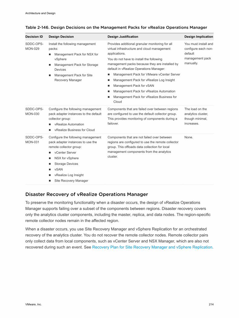
Table 2-146. Design Decisions on the Management Packs for vRealize Operations Manager
Decision ID Design Decision Design Justification Design Implication
SDDC-OPS-MON-029
Install the following managementpacks:
n Management Pack for NSX forvSphere
n Management Pack for StorageDevices
n Management Pack for SiteRecovery Manager
Provides additional granular monitoring for allvirtual infrastructure and cloud managementapplications.
You do not have to install the followingmanagement packs because they are installed bydefault in vRealize Operations Manager:
n Management Pack for VMware vCenter Server
n Management Pack for vRealize Log Insight
n Management Pack for vSAN
n Management Pack for vRealize Automation
n Management Pack for vRealize Business forCloud
You must install andconfigure each non-defaultmanagement packmanually.
SDDC-OPS-MON-030
Configure the following managementpack adapter instances to the defaultcollector group:
n vRealize Automation
n vRealize Business for Cloud
Components that are failed over between regionsare configured to use the default collector group.This provides monitoring of components during afailover.
The load on theanalytics cluster,though minimal,increases.
SDDC-OPS-MON-031
Configure the following managementpack adapter instances to use theremote collector group:
n vCenter Server
n NSX for vSphere
n Storage Devices
n vSAN
n vRealize Log Insight
n Site Recovery Manager
Components that are not failed over betweenregions are configured to use the remote collectorgroup. This offloads data collection for localmanagement components from the analyticscluster.
None.
Disaster Recovery of vRealize Operations ManagerTo preserve the monitoring functionality when a disaster occurs, the design of vRealize OperationsManager supports failing over a subset of the components between regions. Disaster recovery coversonly the analytics cluster components, including the master, replica, and data nodes. The region-specificremote collector nodes remain in the affected region.
When a disaster occurs, you use Site Recovery Manager and vSphere Replication for an orchestratedrecovery of the analytics cluster. You do not recover the remote collector nodes. Remote collector pairsonly collect data from local components, such as vCenter Server and NSX Manager, which are also notrecovered during such an event. See Recovery Plan for Site Recovery Manager and vSphere Replication.
Architecture and Design
VMware, Inc. 214
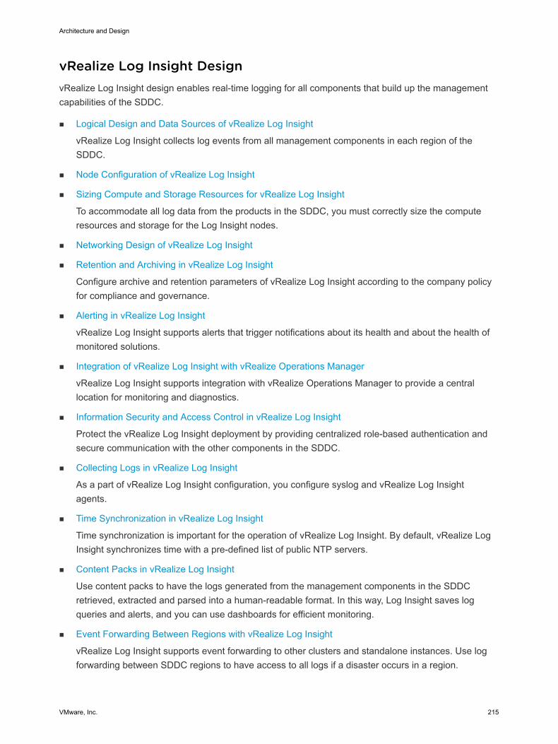
vRealize Log Insight Design vRealize Log Insight design enables real-time logging for all components that build up the managementcapabilities of the SDDC.
n Logical Design and Data Sources of vRealize Log Insight
vRealize Log Insight collects log events from all management components in each region of theSDDC.
n Node Configuration of vRealize Log Insight
n Sizing Compute and Storage Resources for vRealize Log Insight
To accommodate all log data from the products in the SDDC, you must correctly size the computeresources and storage for the Log Insight nodes.
n Networking Design of vRealize Log Insight
n Retention and Archiving in vRealize Log Insight
Configure archive and retention parameters of vRealize Log Insight according to the company policyfor compliance and governance.
n Alerting in vRealize Log Insight
vRealize Log Insight supports alerts that trigger notifications about its health and about the health ofmonitored solutions.
n Integration of vRealize Log Insight with vRealize Operations Manager
vRealize Log Insight supports integration with vRealize Operations Manager to provide a centrallocation for monitoring and diagnostics.
n Information Security and Access Control in vRealize Log Insight
Protect the vRealize Log Insight deployment by providing centralized role-based authentication andsecure communication with the other components in the SDDC.
n Collecting Logs in vRealize Log Insight
As a part of vRealize Log Insight configuration, you configure syslog and vRealize Log Insightagents.
n Time Synchronization in vRealize Log Insight
Time synchronization is important for the operation of vRealize Log Insight. By default, vRealize LogInsight synchronizes time with a pre-defined list of public NTP servers.
n Content Packs in vRealize Log Insight
Use content packs to have the logs generated from the management components in the SDDCretrieved, extracted and parsed into a human-readable format. In this way, Log Insight saves logqueries and alerts, and you can use dashboards for efficient monitoring.
n Event Forwarding Between Regions with vRealize Log Insight
vRealize Log Insight supports event forwarding to other clusters and standalone instances. Use logforwarding between SDDC regions to have access to all logs if a disaster occurs in a region.
Architecture and Design
VMware, Inc. 215
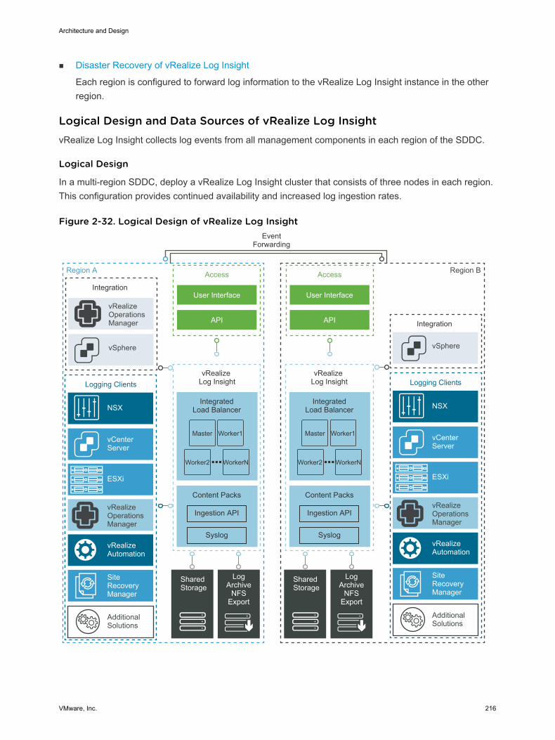
n Disaster Recovery of vRealize Log Insight
Each region is configured to forward log information to the vRealize Log Insight instance in the otherregion.
Logical Design and Data Sources of vRealize Log Insight vRealize Log Insight collects log events from all management components in each region of the SDDC.
Logical Design
In a multi-region SDDC, deploy a vRealize Log Insight cluster that consists of three nodes in each region.This configuration provides continued availability and increased log ingestion rates.
Figure 2-32. Logical Design of vRealize Log Insight
Region A
EventForwarding
Integration
IntegratedLoad Balancer
vSphere
Access
User Interface
API
vRealizeOperationsManager
Content Packs
Syslog
Ingestion API
IntegratedLoad Balancer
Content Packs
Syslog
Ingestion API
Shared Storage
LogArchive
NFSExport
Region B
vRealize Log Insight
vRealize Log Insight
Integration
vSphere
Access
User Interface
API
vRealizeOperationsManager
Logging Clients
vCenter Server
ESXi
NSX
vRealizeAutomation
AdditionalSolutions
Shared Storage
LogArchive
NFSExport
Master Worker1
Worker2 WorkerN
Master Worker1
Worker2 WorkerN
SiteRecoveryManager
vRealizeOperationsManager
Logging Clients
vCenter Server
ESXi
NSX
vRealizeAutomation
AdditionalSolutions
SiteRecoveryManager
Architecture and Design
VMware, Inc. 216
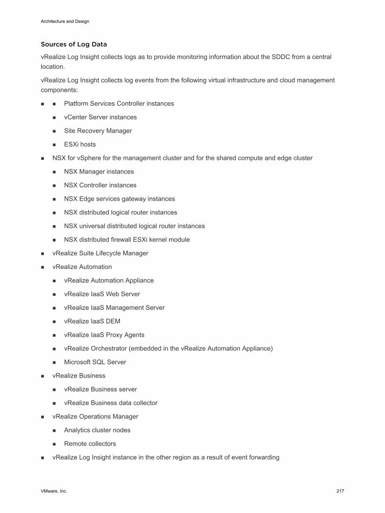
Sources of Log Data
vRealize Log Insight collects logs as to provide monitoring information about the SDDC from a centrallocation.
vRealize Log Insight collects log events from the following virtual infrastructure and cloud managementcomponents:
n n Platform Services Controller instances
n vCenter Server instances
n Site Recovery Manager
n ESXi hosts
n NSX for vSphere for the management cluster and for the shared compute and edge cluster
n NSX Manager instances
n NSX Controller instances
n NSX Edge services gateway instances
n NSX distributed logical router instances
n NSX universal distributed logical router instances
n NSX distributed firewall ESXi kernel module
n vRealize Suite Lifecycle Manager
n vRealize Automation
n vRealize Automation Appliance
n vRealize IaaS Web Server
n vRealize IaaS Management Server
n vRealize IaaS DEM
n vRealize IaaS Proxy Agents
n vRealize Orchestrator (embedded in the vRealize Automation Appliance)
n Microsoft SQL Server
n vRealize Business
n vRealize Business server
n vRealize Business data collector
n vRealize Operations Manager
n Analytics cluster nodes
n Remote collectors
n vRealize Log Insight instance in the other region as a result of event forwarding
Architecture and Design
VMware, Inc. 217
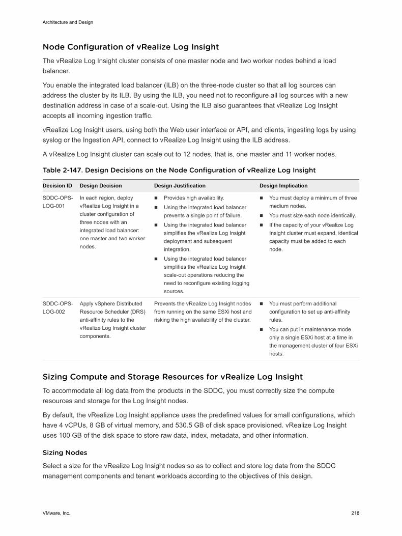
Node Configuration of vRealize Log Insight The vRealize Log Insight cluster consists of one master node and two worker nodes behind a loadbalancer.
You enable the integrated load balancer (ILB) on the three-node cluster so that all log sources canaddress the cluster by its ILB. By using the ILB, you need not to reconfigure all log sources with a newdestination address in case of a scale-out. Using the ILB also guarantees that vRealize Log Insightaccepts all incoming ingestion traffic.
vRealize Log Insight users, using both the Web user interface or API, and clients, ingesting logs by usingsyslog or the Ingestion API, connect to vRealize Log Insight using the ILB address.
A vRealize Log Insight cluster can scale out to 12 nodes, that is, one master and 11 worker nodes.
Table 2-147. Design Decisions on the Node Configuration of vRealize Log Insight
Decision ID Design Decision Design Justification Design Implication
SDDC-OPS-LOG-001
In each region, deployvRealize Log Insight in acluster configuration ofthree nodes with anintegrated load balancer:one master and two workernodes.
n Provides high availability.
n Using the integrated load balancerprevents a single point of failure.
n Using the integrated load balancersimplifies the vRealize Log Insightdeployment and subsequentintegration.
n Using the integrated load balancersimplifies the vRealize Log Insightscale-out operations reducing theneed to reconfigure existing loggingsources.
n You must deploy a minimum of threemedium nodes.
n You must size each node identically.
n If the capacity of your vRealize LogInsight cluster must expand, identicalcapacity must be added to eachnode.
SDDC-OPS-LOG-002
Apply vSphere DistributedResource Scheduler (DRS)anti-affinity rules to thevRealize Log Insight clustercomponents.
Prevents the vRealize Log Insight nodesfrom running on the same ESXi host andrisking the high availability of the cluster.
n You must perform additionalconfiguration to set up anti-affinityrules.
n You can put in maintenance modeonly a single ESXi host at a time inthe management cluster of four ESXihosts.
Sizing Compute and Storage Resources for vRealize Log Insight To accommodate all log data from the products in the SDDC, you must correctly size the computeresources and storage for the Log Insight nodes.
By default, the vRealize Log Insight appliance uses the predefined values for small configurations, whichhave 4 vCPUs, 8 GB of virtual memory, and 530.5 GB of disk space provisioned. vRealize Log Insightuses 100 GB of the disk space to store raw data, index, metadata, and other information.
Sizing Nodes
Select a size for the vRealize Log Insight nodes so as to collect and store log data from the SDDCmanagement components and tenant workloads according to the objectives of this design.
Architecture and Design
VMware, Inc. 218
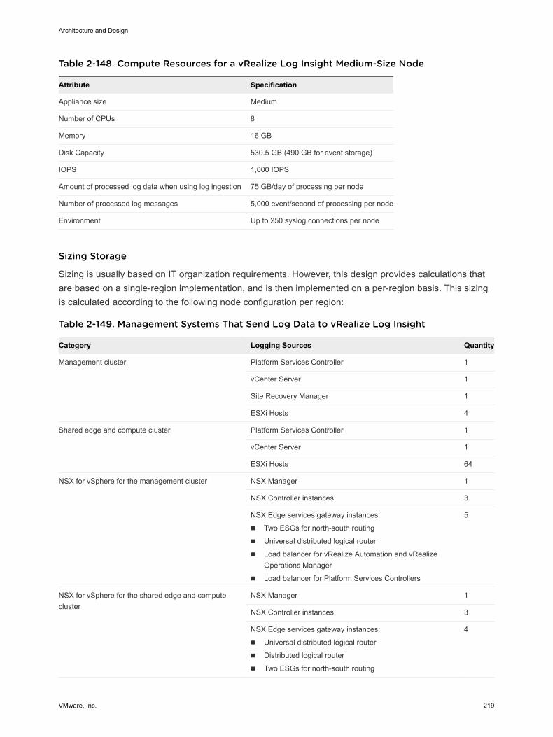
Table 2-148. Compute Resources for a vRealize Log Insight Medium-Size Node
Attribute Specification
Appliance size Medium
Number of CPUs 8
Memory 16 GB
Disk Capacity 530.5 GB (490 GB for event storage)
IOPS 1,000 IOPS
Amount of processed log data when using log ingestion 75 GB/day of processing per node
Number of processed log messages 5,000 event/second of processing per node
Environment Up to 250 syslog connections per node
Sizing Storage
Sizing is usually based on IT organization requirements. However, this design provides calculations thatare based on a single-region implementation, and is then implemented on a per-region basis. This sizingis calculated according to the following node configuration per region:
Table 2-149. Management Systems That Send Log Data to vRealize Log Insight
Category Logging Sources Quantity
Management cluster Platform Services Controller 1
vCenter Server 1
Site Recovery Manager 1
ESXi Hosts 4
Shared edge and compute cluster Platform Services Controller 1
vCenter Server 1
ESXi Hosts 64
NSX for vSphere for the management cluster NSX Manager 1
NSX Controller instances 3
NSX Edge services gateway instances:
n Two ESGs for north-south routing
n Universal distributed logical router
n Load balancer for vRealize Automation and vRealizeOperations Manager
n Load balancer for Platform Services Controllers
5
NSX for vSphere for the shared edge and computecluster
NSX Manager 1
NSX Controller instances 3
NSX Edge services gateway instances:
n Universal distributed logical router
n Distributed logical router
n Two ESGs for north-south routing
4
Architecture and Design
VMware, Inc. 219
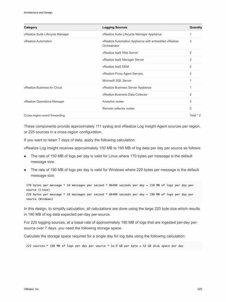
Category Logging Sources Quantity
vRealize Suite Lifecycle Manager vRealize Suite Lifecycle Manager Appliance 1
vRealize Automation vRealize Automation Appliance with embedded vRealizeOrchestrator
3
vRealize IaaS Web Server 2
vRealize IaaS Manager Server 2
vRealize IaaS DEM 2
vRealize Proxy Agent Servers 2
Microsoft SQL Server 1
vRealize Business for Cloud vRealize Business Server Appliance 1
vRealize Business Data Collector 2
vRealize Operations Manager Analytics nodes 3
Remote collector nodes 2
Cross-region event forwarding Total * 2
These components provide approximately 111 syslog and vRealize Log Insight Agent sources per region,or 225 sources in a cross-region configuration.
If you want to retain 7 days of data, apply the following calculation:
vRealize Log Insight receives approximately 150 MB to 190 MB of log data per day per source as follows:
n The rate of 150 MB of logs per day is valid for Linux where 170 bytes per message is the defaultmessage size.
n The rate of 190 MB of logs per day is valid for Windows where 220 bytes per message is the defaultmessage size.
170 bytes per message * 10 messages per second * 86400 seconds per day = 150 MB of logs per day per
source (Linux)
220 bytes per message * 10 messages per second * 86400 seconds per day = 190 MB of logs per day per
source (Windows)
In this design, to simplify calculation, all calculations are done using the large 220 byte size which resultsin 190 MB of log data expected per-day per-source.
For 225 logging sources, at a basal rate of approximately 190 MB of logs that are ingested per-day per-source over 7 days, you need the following storage space:
Calculate the storage space required for a single day for log data using the following calculation:
225 sources * 190 MB of logs per day per source * 1e-9 GB per byte ≈ 42 GB disk space per day
Architecture and Design
VMware, Inc. 220
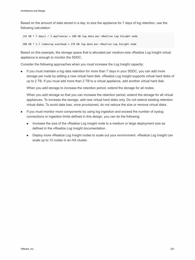
Based on the amount of data stored in a day, to size the appliance for 7 days of log retention, use thefollowing calculation:
(42 GB * 7 days) / 3 аppliances ≈ 100 GB log data per vRealize Log Insight node
100 GB * 1.7 indexing overhead ≈ 170 GB log data per vRealize Log Insight node
Based on this example, the storage space that is allocated per medium-size vRealize Log Insight virtualappliance is enough to monitor the SDDC.
Consider the following approaches when you must increase the Log Insight capacity:
n If you must maintain a log data retention for more than 7 days in your SDDC, you can add morestorage per node by adding a new virtual hard disk. vRealize Log Insight supports virtual hard disks ofup to 2 TB. If you must add more than 2 TB to a virtual appliance, add another virtual hard disk.
When you add storage to increase the retention period, extend the storage for all nodes.
When you add storage so that you can increase the retention period, extend the storage for all virtualappliances. To increase the storage, add new virtual hard disks only. Do not extend existing retentionvirtual disks. To avoid data loss, once provisioned, do not reduce the size or remove virtual disks .
n If you must monitor more components by using log ingestion and exceed the number of syslogconnections or ingestion limits defined in this design, you can do the following:
n Increase the size of the vRealize Log Insight node to a medium or large deployment size asdefined in the vRealize Log Insight documentation.
n Deploy more vRealize Log Insight nodes to scale out your environment. vRealize Log Insight canscale up to 12 nodes in an HA cluster.
Architecture and Design
VMware, Inc. 221
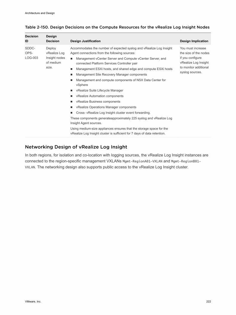
Table 2-150. Design Decisions on the Compute Resources for the vRealize Log Insight Nodes
DecisionID
DesignDecision Design Justification Design Implication
SDDC-OPS-LOG-003
DeployvRealize LogInsight nodesof mediumsize.
Accommodates the number of expected syslog and vRealize Log InsightAgent connections from the following sources:
n Management vCenter Server and Compute vCenter Server, andconnected Platform Services Controller pair
n Management ESXi hosts, and shared edge and compute ESXi hosts
n Management Site Recovery Manager components
n Management and compute components of NSX Data Center forvSphere
n vRealize Suite Lifecycle Manager
n vRealize Automation components
n vRealize Business components
n vRealize Operations Manager components
n Cross- vRealize Log Insight cluster event forwarding.
These components generateapproximately 225 syslog and vRealize LogInsight Agent sources.
Using medium-size appliances ensures that the storage space for thevRealize Log Insight cluster is sufficient for 7 days of data retention.
You must increasethe size of the nodesif you configurevRealize Log Insightto monitor additionalsyslog sources.
Networking Design of vRealize Log Insight In both regions, for isolation and co-location with logging sources, the vRealize Log Insight instances areconnected to the region-specific management VXLANs Mgmt-RegionA01-VXLAN and Mgmt-RegionB01-VXLAN. The networking design also supports public access to the vRealize Log Insight cluster.
Architecture and Design
VMware, Inc. 222
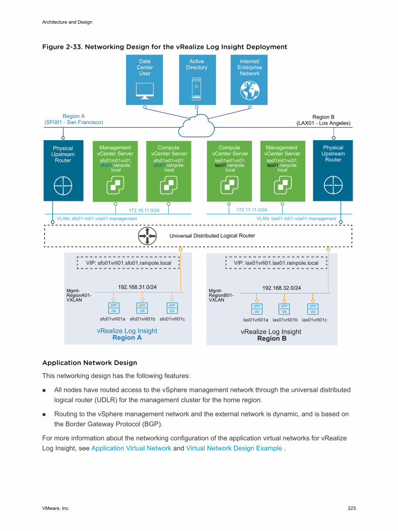
Figure 2-33. Networking Design for the vRealize Log Insight Deployment
APP
OSAPP
OSAPP
OS
APP
OSAPP
OSAPP
OS
192.168.32.0/24
vRealize Log Insight Region B
192.168.31.0/24Mgmt-RegionA01-VXLAN
vRealize Log Insight Region A
Universal Distributed Logical Router
Mgmt-RegionB01-VXLAN
DataCenterUser
ActiveDirectory
Internet/EnterpriseNetwork
Region A(SF001 - San Francisco)
Management vCenter Serverlax01m01vc01.lax01.rainpole.
local
Compute vCenter Serverlax01w01vc01.lax01.rainpole.
local
VLAN: sfo01-m01-vds01-management
172.16.11.0/24
VLAN: lax01-m01-vds01-management
172.17.11.0/24
Management vCenter Server
sfo01m01vc01.sfo01.rainpole.
local
Compute vCenter Serversfo01w01vc01.sfo01.rainpole.
local
PhysicalUpstream
Router
Region B(LAX01 - Los Angeles)
PhysicalUpstream
Router
VIP: lax01vrli01.lax01.rainpole.local
lax01vrli01a lax01vrli01b lax01vrli01csfo01vrli01a sfo01vrli01b sfo01vrli01c
VIP: sfo01vrli01.sfo01.rainpole.local
Application Network Design
This networking design has the following features:
n All nodes have routed access to the vSphere management network through the universal distributedlogical router (UDLR) for the management cluster for the home region.
n Routing to the vSphere management network and the external network is dynamic, and is based onthe Border Gateway Protocol (BGP).
For more information about the networking configuration of the application virtual networks for vRealizeLog Insight, see Application Virtual Network and Virtual Network Design Example .
Architecture and Design
VMware, Inc. 223
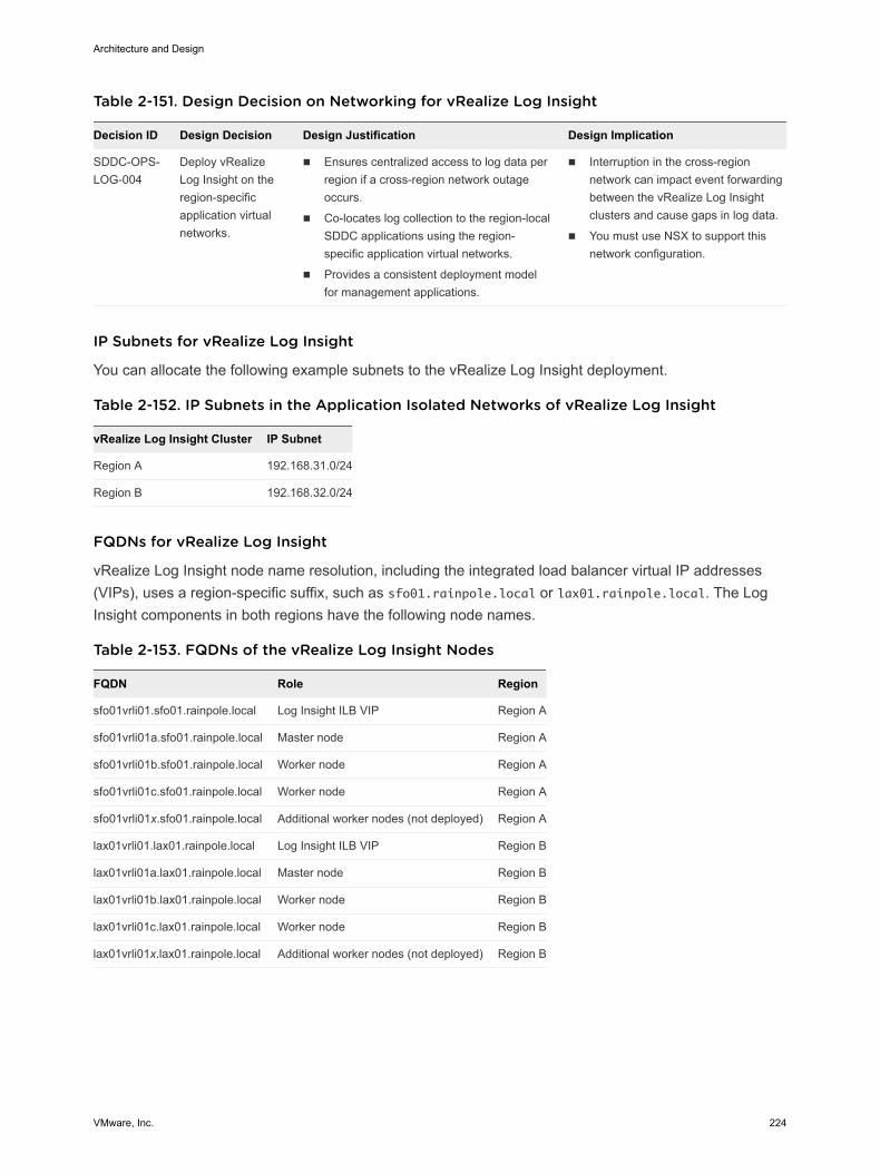
Table 2-151. Design Decision on Networking for vRealize Log Insight
Decision ID Design Decision Design Justification Design Implication
SDDC-OPS-LOG-004
Deploy vRealizeLog Insight on theregion-specificapplication virtualnetworks.
n Ensures centralized access to log data perregion if a cross-region network outageoccurs.
n Co-locates log collection to the region-localSDDC applications using the region-specific application virtual networks.
n Provides a consistent deployment modelfor management applications.
n Interruption in the cross-regionnetwork can impact event forwardingbetween the vRealize Log Insightclusters and cause gaps in log data.
n You must use NSX to support thisnetwork configuration.
IP Subnets for vRealize Log Insight
You can allocate the following example subnets to the vRealize Log Insight deployment.
Table 2-152. IP Subnets in the Application Isolated Networks of vRealize Log Insight
vRealize Log Insight Cluster IP Subnet
Region A 192.168.31.0/24
Region B 192.168.32.0/24
FQDNs for vRealize Log Insight
vRealize Log Insight node name resolution, including the integrated load balancer virtual IP addresses(VIPs), uses a region-specific suffix, such as sfo01.rainpole.local or lax01.rainpole.local. The LogInsight components in both regions have the following node names.
Table 2-153. FQDNs of the vRealize Log Insight Nodes
FQDN Role Region
sfo01vrli01.sfo01.rainpole.local Log Insight ILB VIP Region A
sfo01vrli01a.sfo01.rainpole.local Master node Region A
sfo01vrli01b.sfo01.rainpole.local Worker node Region A
sfo01vrli01c.sfo01.rainpole.local Worker node Region A
sfo01vrli01x.sfo01.rainpole.local Additional worker nodes (not deployed) Region A
lax01vrli01.lax01.rainpole.local Log Insight ILB VIP Region B
lax01vrli01a.lax01.rainpole.local Master node Region B
lax01vrli01b.lax01.rainpole.local Worker node Region B
lax01vrli01c.lax01.rainpole.local Worker node Region B
lax01vrli01x.lax01.rainpole.local Additional worker nodes (not deployed) Region B
Architecture and Design
VMware, Inc. 224
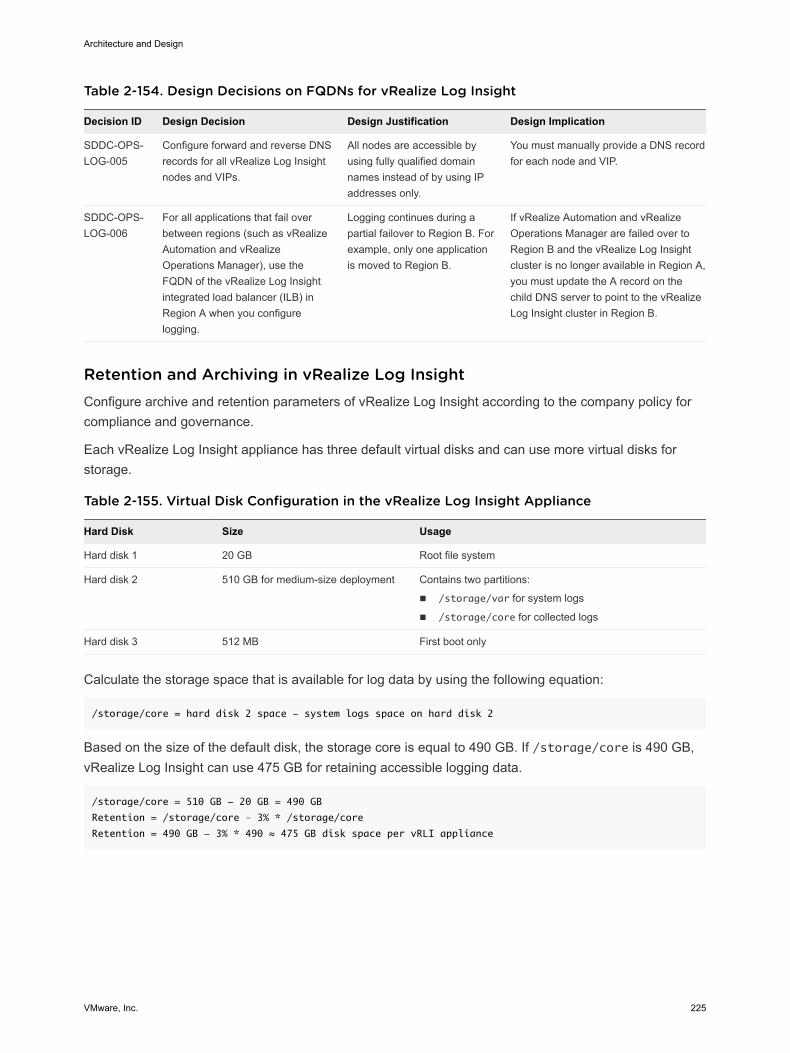
Table 2-154. Design Decisions on FQDNs for vRealize Log Insight
Decision ID Design Decision Design Justification Design Implication
SDDC-OPS-LOG-005
Configure forward and reverse DNSrecords for all vRealize Log Insightnodes and VIPs.
All nodes are accessible byusing fully qualified domainnames instead of by using IPaddresses only.
You must manually provide a DNS recordfor each node and VIP.
SDDC-OPS-LOG-006
For all applications that fail overbetween regions (such as vRealizeAutomation and vRealizeOperations Manager), use theFQDN of the vRealize Log Insightintegrated load balancer (ILB) inRegion A when you configurelogging.
Logging continues during apartial failover to Region B. Forexample, only one applicationis moved to Region B.
If vRealize Automation and vRealizeOperations Manager are failed over toRegion B and the vRealize Log Insightcluster is no longer available in Region A,you must update the A record on thechild DNS server to point to the vRealizeLog Insight cluster in Region B.
Retention and Archiving in vRealize Log Insight Configure archive and retention parameters of vRealize Log Insight according to the company policy forcompliance and governance.
Each vRealize Log Insight appliance has three default virtual disks and can use more virtual disks forstorage.
Table 2-155. Virtual Disk Configuration in the vRealize Log Insight Appliance
Hard Disk Size Usage
Hard disk 1 20 GB Root file system
Hard disk 2 510 GB for medium-size deployment Contains two partitions:
n /storage/var for system logs
n /storage/core for collected logs
Hard disk 3 512 MB First boot only
Calculate the storage space that is available for log data by using the following equation:
/storage/core = hard disk 2 space - system logs space on hard disk 2
Based on the size of the default disk, the storage core is equal to 490 GB. If /storage/core is 490 GB,vRealize Log Insight can use 475 GB for retaining accessible logging data.
/storage/core = 510 GB - 20 GB = 490 GB
Retention = /storage/core – 3% * /storage/core
Retention = 490 GB - 3% * 490 ≈ 475 GB disk space per vRLI appliance
Architecture and Design
VMware, Inc. 225
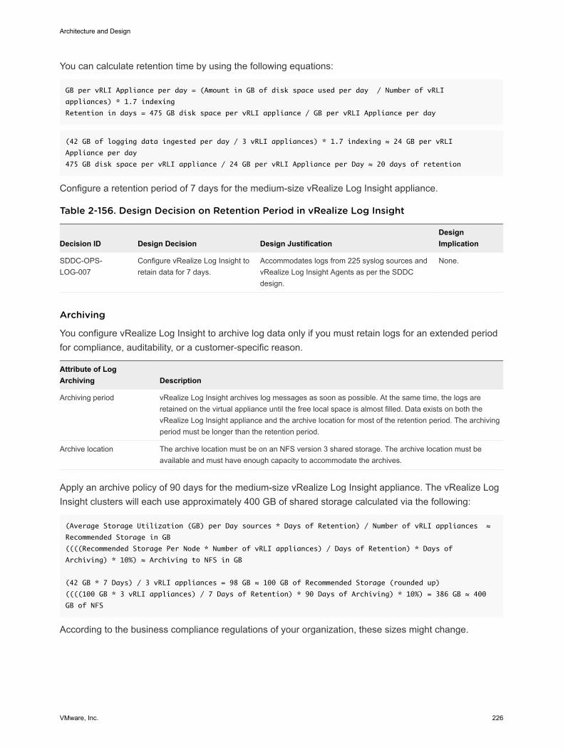
You can calculate retention time by using the following equations:
GB per vRLI Appliance per day = (Amount in GB of disk space used per day / Number of vRLI
appliances) * 1.7 indexing
Retention in days = 475 GB disk space per vRLI appliance / GB per vRLI Appliance per day
(42 GB of logging data ingested per day / 3 vRLI appliances) * 1.7 indexing ≈ 24 GB per vRLI
Appliance per day
475 GB disk space per vRLI appliance / 24 GB per vRLI Appliance per Day ≈ 20 days of retention
Configure a retention period of 7 days for the medium-size vRealize Log Insight appliance.
Table 2-156. Design Decision on Retention Period in vRealize Log Insight
Decision ID Design Decision Design JustificationDesignImplication
SDDC-OPS-LOG-007
Configure vRealize Log Insight toretain data for 7 days.
Accommodates logs from 225 syslog sources andvRealize Log Insight Agents as per the SDDCdesign.
None.
Archiving
You configure vRealize Log Insight to archive log data only if you must retain logs for an extended periodfor compliance, auditability, or a customer-specific reason.
Attribute of LogArchiving Description
Archiving period vRealize Log Insight archives log messages as soon as possible. At the same time, the logs areretained on the virtual appliance until the free local space is almost filled. Data exists on both thevRealize Log Insight appliance and the archive location for most of the retention period. The archivingperiod must be longer than the retention period.
Archive location The archive location must be on an NFS version 3 shared storage. The archive location must beavailable and must have enough capacity to accommodate the archives.
Apply an archive policy of 90 days for the medium-size vRealize Log Insight appliance. The vRealize LogInsight clusters will each use approximately 400 GB of shared storage calculated via the following:
(Average Storage Utilization (GB) per Day sources * Days of Retention) / Number of vRLI appliances ≈
Recommended Storage in GB
((((Recommended Storage Per Node * Number of vRLI appliances) / Days of Retention) * Days of
Archiving) * 10%) ≈ Archiving to NFS in GB
(42 GB * 7 Days) / 3 vRLI appliances = 98 GB ≈ 100 GB of Recommended Storage (rounded up)
((((100 GB * 3 vRLI appliances) / 7 Days of Retention) * 90 Days of Archiving) * 10%) = 386 GB ≈ 400
GB of NFS
According to the business compliance regulations of your organization, these sizes might change.
Architecture and Design
VMware, Inc. 226
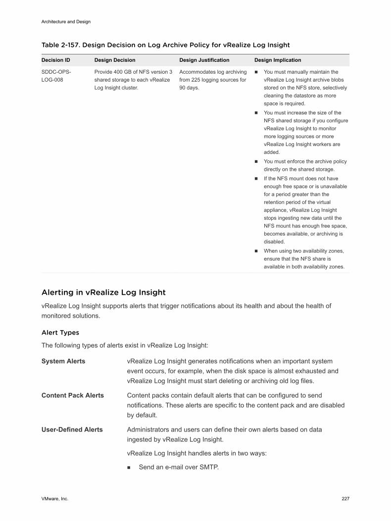
Table 2-157. Design Decision on Log Archive Policy for vRealize Log Insight
Decision ID Design Decision Design Justification Design Implication
SDDC-OPS-LOG-008
Provide 400 GB of NFS version 3shared storage to each vRealizeLog Insight cluster.
Accommodates log archivingfrom 225 logging sources for90 days.
n You must manually maintain thevRealize Log Insight archive blobsstored on the NFS store, selectivelycleaning the datastore as morespace is required.
n You must increase the size of theNFS shared storage if you configurevRealize Log Insight to monitormore logging sources or morevRealize Log Insight workers areadded.
n You must enforce the archive policydirectly on the shared storage.
n If the NFS mount does not haveenough free space or is unavailablefor a period greater than theretention period of the virtualappliance, vRealize Log Insightstops ingesting new data until theNFS mount has enough free space,becomes available, or archiving isdisabled.
n When using two availability zones,ensure that the NFS share isavailable in both availability zones.
Alerting in vRealize Log Insight vRealize Log Insight supports alerts that trigger notifications about its health and about the health ofmonitored solutions.
Alert Types
The following types of alerts exist in vRealize Log Insight:
System Alerts vRealize Log Insight generates notifications when an important systemevent occurs, for example, when the disk space is almost exhausted andvRealize Log Insight must start deleting or archiving old log files.
Content Pack Alerts Content packs contain default alerts that can be configured to sendnotifications. These alerts are specific to the content pack and are disabledby default.
User-Defined Alerts Administrators and users can define their own alerts based on dataingested by vRealize Log Insight.
vRealize Log Insight handles alerts in two ways:
n Send an e-mail over SMTP.
Architecture and Design
VMware, Inc. 227
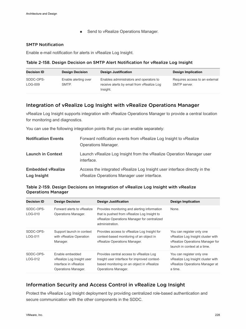
n Send to vRealize Operations Manager.
SMTP Notification
Enable e-mail notification for alerts in vRealize Log Insight.
Table 2-158. Design Decision on SMTP Alert Notification for vRealize Log Insight
Decision ID Design Decision Design Justification Design Implication
SDDC-OPS-LOG-009
Enable alerting overSMTP.
Enables administrators and operators toreceive alerts by email from vRealize LogInsight.
Requires access to an externalSMTP server.
Integration of vRealize Log Insight with vRealize Operations Manager vRealize Log Insight supports integration with vRealize Operations Manager to provide a central locationfor monitoring and diagnostics.
You can use the following integration points that you can enable separately:
Notification Events Forward notification events from vRealize Log Insight to vRealizeOperations Manager.
Launch in Context Launch vRealize Log Insight from the vRealize Operation Manager userinterface.
Embedded vRealizeLog Insight
Access the integrated vRealize Log Insight user interface directly in thevRealize Operations Manager user interface.
Table 2-159. Design Decisions on Integration of vRealize Log Insight with vRealizeOperations Manager
Decision ID Design Decision Design Justification Design Implication
SDDC-OPS-LOG-010
Forward alerts to vRealizeOperations Manager.
Provides monitoring and alerting informationthat is pushed from vRealize Log Insight tovRealize Operations Manager for centralizedadministration.
None.
SDDC-OPS-LOG-011
Support launch in contextwith vRealize OperationManager.
Provides access to vRealize Log Insight forcontext-based monitoring of an object invRealize Operations Manager.
You can register only onevRealize Log Insight cluster withvRealize Operations Manager forlaunch in context at a time.
SDDC-OPS-LOG-012
Enable embeddedvRealize Log Insight userinterface in vRealizeOperations Manager.
Provides central access to vRealize LogInsight user interface for improved context-based monitoring on an object in vRealizeOperations Manager.
You can register only onevRealize Log Insight cluster withvRealize Operations Manager ata time.
Information Security and Access Control in vRealize Log Insight Protect the vRealize Log Insight deployment by providing centralized role-based authentication andsecure communication with the other components in the SDDC.
Architecture and Design
VMware, Inc. 228
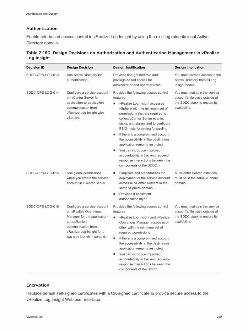
Authentication
Enable role-based access control in vRealize Log Insight by using the existing rainpole.local ActiveDirectory domain.
Table 2-160. Design Decisions on Authorization and Authentication Management in vRealizeLog Insight
Decision ID Design Decision Design Justification Design Implication
SDDC-OPS-LOG-013 Use Active Directory forauthentication.
Provides fine-grained role andprivilege-based access foradministrator and operator roles.
You must provide access to theActive Directory from all LogInsight nodes.
SDDC-OPS-LOG-014 Configure a service accounton vCenter Server forapplication-to-applicationcommunication fromvRealize Log Insight withvSphere.
Provides the following access controlfeatures:
n vRealize Log Insight accessesvSphere with the minimum set ofpermissions that are required tocollect vCenter Server events,tasks, and alarms and to configureESXi hosts for syslog forwarding.
n If there is a compromised account,the accessibility in the destinationapplication remains restricted.
n You can introduce improvedaccountability in tracking request-response interactions between thecomponents of the SDDC.
You must maintain the serviceaccount's life cycle outside ofthe SDDC stack to ensure itsavailability.
SDDC-OPS-LOG-015 Use global permissionswhen you create the serviceaccount in vCenter Server.
n Simplifies and standardizes thedeployment of the service accountacross all vCenter Servers in thesame vSphere domain.
n Provides a consistentauthorization layer.
All vCenter Server instancesmust be in the same vSpheredomain.
SDDC-OPS-LOG-016 Configure a service accounton vRealize OperationsManager for the application-to-applicationcommunication fromvRealize Log Insight for atwo-way launch in context.
Provides the following access controlfeatures:
n vRealize Log Insight and vRealizeOperations Manager access eachother with the minimum set ofrequired permissions.
n If there is a compromised account,the accessibility in the destinationapplication remains restricted.
n You can introduce improvedaccountability in tracking request-response interactions between thecomponents of the SDDC.
You must maintain the serviceaccount's life cycle outside ofthe SDDC stack to ensure itsavailability.
Encryption
Replace default self-signed certificates with a CA-signed certificate to provide secure access to thevRealize Log Insight Web user interface.
Architecture and Design
VMware, Inc. 229
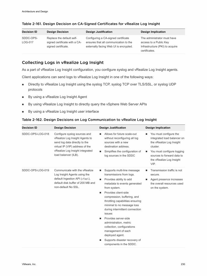
Table 2-161. Design Decision on CA-Signed Certificates for vRealize Log Insight
Decision ID Design Decision Design Justification Design Implication
SDDC-OPS-LOG-017
Replace the default self-signed certificate with a CA-signed certificate.
Configuring a CA-signed certificateensures that all communication to theexternally facing Web UI is encrypted.
The administrator must haveaccess to a Public KeyInfrastructure (PKI) to acquirecertificates.
Collecting Logs in vRealize Log Insight As a part of vRealize Log Insight configuration, you configure syslog and vRealize Log Insight agents.
Client applications can send logs to vRealize Log Insight in one of the following ways:
n Directly to vRealize Log Insight using the syslog TCP, syslog TCP over TLS/SSL, or syslog UDPprotocols
n By using a vRealize Log Insight Agent
n By using vRealize Log Insight to directly query the vSphere Web Server APIs
n By using a vRealize Log Insight user interface
Table 2-162. Design Decisions on Log Communication to vRealize Log Insight
Decision ID Design Decision Design Justification Design Implication
SDDC-OPS-LOG-018 Configure syslog sources andvRealize Log Insight Agents tosend log data directly to thevirtual IP (VIP) address of thevRealize Log Insight integratedload balancer (ILB).
n Allows for future scale-outwithout reconfiguring all logsources with a newdestination address.
n Simplifies the configuration oflog sources in the SDDC
n You must configure theintegrated load balancer onthe vRealize Log Insightcluster.
n You must configure loggingsources to forward data tothe vRealize Log InsightVIP.
SDDC-OPS-LOG-019 Communicate with the vRealizeLog Insight Agents using thedefault Ingestion API (cfapi),default disk buffer of 200 MB andnon-default No SSL.
n Supports multi-line messagetransmissions from logs.
n Provides ability to addmetadata to events generatedfrom system.
n Provides client-sidecompression, buffering, andthrottling capabilities ensuringminimal to no message lossduring intermittent connectionissues
n Provides server-sideadministration, metriccollection, configurationsmanagement of eachdeployed agent.
n Supports disaster recovery ofcomponents in the SDDC.
n Transmission traffic is notsecure.
n Agent presence increasesthe overall resources usedon the system.
Architecture and Design
VMware, Inc. 230
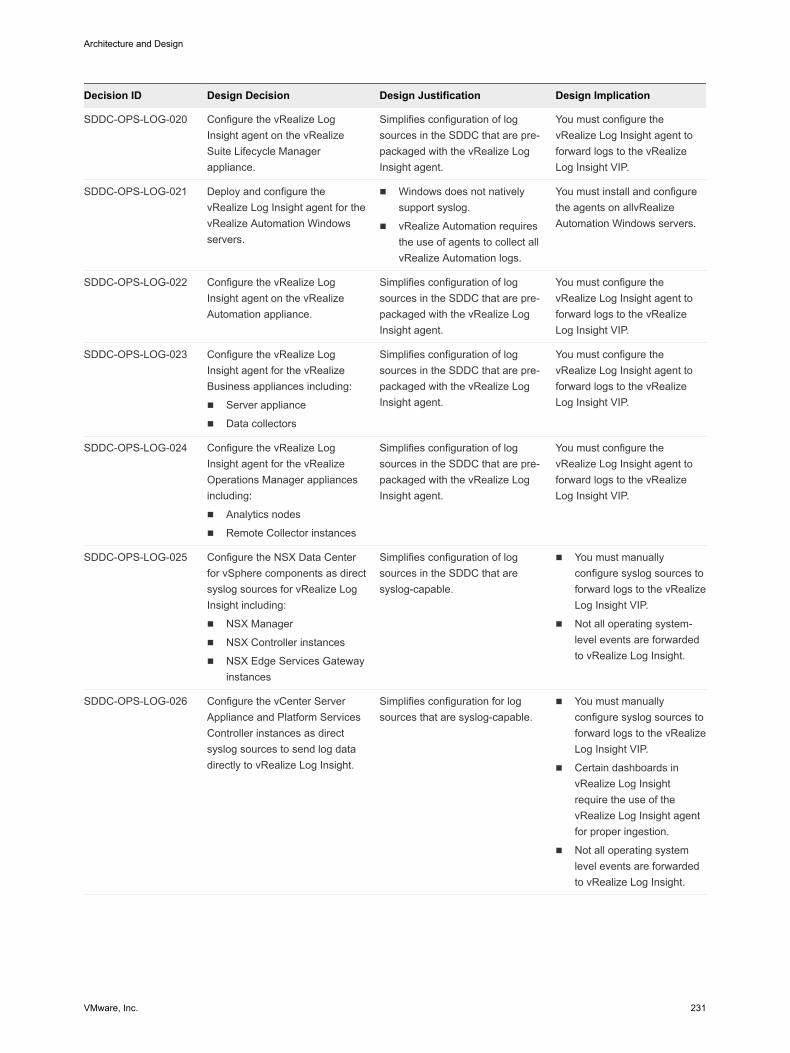
Decision ID Design Decision Design Justification Design Implication
SDDC-OPS-LOG-020 Configure the vRealize LogInsight agent on the vRealizeSuite Lifecycle Managerappliance.
Simplifies configuration of logsources in the SDDC that are pre-packaged with the vRealize LogInsight agent.
You must configure thevRealize Log Insight agent toforward logs to the vRealizeLog Insight VIP.
SDDC-OPS-LOG-021 Deploy and configure thevRealize Log Insight agent for thevRealize Automation Windowsservers.
n Windows does not nativelysupport syslog.
n vRealize Automation requiresthe use of agents to collect allvRealize Automation logs.
You must install and configurethe agents on allvRealizeAutomation Windows servers.
SDDC-OPS-LOG-022 Configure the vRealize LogInsight agent on the vRealizeAutomation appliance.
Simplifies configuration of logsources in the SDDC that are pre-packaged with the vRealize LogInsight agent.
You must configure thevRealize Log Insight agent toforward logs to the vRealizeLog Insight VIP.
SDDC-OPS-LOG-023 Configure the vRealize LogInsight agent for the vRealizeBusiness appliances including:
n Server appliance
n Data collectors
Simplifies configuration of logsources in the SDDC that are pre-packaged with the vRealize LogInsight agent.
You must configure thevRealize Log Insight agent toforward logs to the vRealizeLog Insight VIP.
SDDC-OPS-LOG-024 Configure the vRealize LogInsight agent for the vRealizeOperations Manager appliancesincluding:
n Analytics nodes
n Remote Collector instances
Simplifies configuration of logsources in the SDDC that are pre-packaged with the vRealize LogInsight agent.
You must configure thevRealize Log Insight agent toforward logs to the vRealizeLog Insight VIP.
SDDC-OPS-LOG-025 Configure the NSX Data Centerfor vSphere components as directsyslog sources for vRealize LogInsight including:
n NSX Manager
n NSX Controller instances
n NSX Edge Services Gatewayinstances
Simplifies configuration of logsources in the SDDC that aresyslog-capable.
n You must manuallyconfigure syslog sources toforward logs to the vRealizeLog Insight VIP.
n Not all operating system-level events are forwardedto vRealize Log Insight.
SDDC-OPS-LOG-026 Configure the vCenter ServerAppliance and Platform ServicesController instances as directsyslog sources to send log datadirectly to vRealize Log Insight.
Simplifies configuration for logsources that are syslog-capable.
n You must manuallyconfigure syslog sources toforward logs to the vRealizeLog Insight VIP.
n Certain dashboards invRealize Log Insightrequire the use of thevRealize Log Insight agentfor proper ingestion.
n Not all operating systemlevel events are forwardedto vRealize Log Insight.
Architecture and Design
VMware, Inc. 231
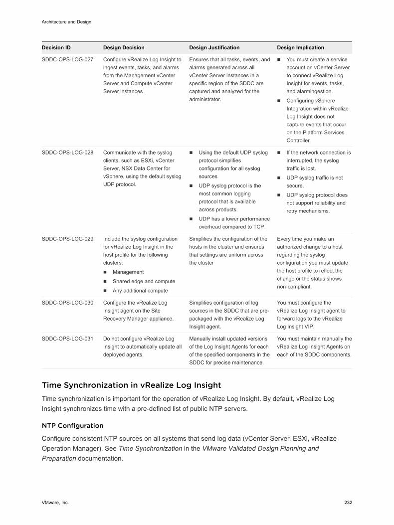
Decision ID Design Decision Design Justification Design Implication
SDDC-OPS-LOG-027 Configure vRealize Log Insight toingest events, tasks, and alarmsfrom the Management vCenterServer and Compute vCenterServer instances .
Ensures that all tasks, events, andalarms generated across allvCenter Server instances in aspecific region of the SDDC arecaptured and analyzed for theadministrator.
n You must create a serviceaccount on vCenter Serverto connect vRealize LogInsight for events, tasks,and alarmingestion.
n Configuring vSphereIntegration within vRealizeLog Insight does notcapture events that occuron the Platform ServicesController.
SDDC-OPS-LOG-028 Communicate with the syslogclients, such as ESXi, vCenterServer, NSX Data Center forvSphere, using the default syslogUDP protocol.
n Using the default UDP syslogprotocol simplifiesconfiguration for all syslogsources
n UDP syslog protocol is themost common loggingprotocol that is availableacross products.
n UDP has a lower performanceoverhead compared to TCP.
n If the network connection isinterrupted, the syslogtraffic is lost.
n UDP syslog traffic is notsecure.
n UDP syslog protocol doesnot support reliability andretry mechanisms.
SDDC-OPS-LOG-029 Include the syslog configurationfor vRealize Log Insight in thehost profile for the followingclusters:
n Management
n Shared edge and compute
n Any additional compute
Simplifies the configuration of thehosts in the cluster and ensuresthat settings are uniform acrossthe cluster
Every time you make anauthorized change to a hostregarding the syslogconfiguration you must updatethe host profile to reflect thechange or the status showsnon-compliant.
SDDC-OPS-LOG-030 Configure the vRealize LogInsight agent on the SiteRecovery Manager appliance.
Simplifies configuration of logsources in the SDDC that are pre-packaged with the vRealize LogInsight agent.
You must configure thevRealize Log Insight agent toforward logs to the vRealizeLog Insight VIP.
SDDC-OPS-LOG-031 Do not configure vRealize LogInsight to automatically update alldeployed agents.
Manually install updated versionsof the Log Insight Agents for eachof the specified components in theSDDC for precise maintenance.
You must maintain manually thevRealize Log Insight Agents oneach of the SDDC components.
Time Synchronization in vRealize Log Insight Time synchronization is important for the operation of vRealize Log Insight. By default, vRealize LogInsight synchronizes time with a pre-defined list of public NTP servers.
NTP Configuration
Configure consistent NTP sources on all systems that send log data (vCenter Server, ESXi, vRealizeOperation Manager). See Time Synchronization in the VMware Validated Design Planning andPreparation documentation.
Architecture and Design
VMware, Inc. 232
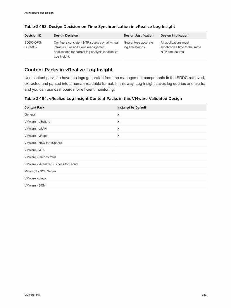
Table 2-163. Design Decision on Time Synchronization in vRealize Log Insight
Decision ID Design Decision Design Justification Design Implication
SDDC-OPS-LOG-032
Configure consistent NTP sources on all virtualinfrastructure and cloud managementapplications for correct log analysis in vRealizeLog Insight.
Guarantees accuratelog timestamps.
All applications mustsynchronize time to the sameNTP time source.
Content Packs in vRealize Log Insight Use content packs to have the logs generated from the management components in the SDDC retrieved,extracted and parsed into a human-readable format. In this way, Log Insight saves log queries and alerts,and you can use dashboards for efficient monitoring.
Table 2-164. vRealize Log Insight Content Packs in this VMware Validated Design
Content Pack Installed by Default
General X
VMware - vSphere X
VMware - vSAN X
VMware - vRops X
VMware - NSX for vSphere
VMware - vRA
VMware - Orchestrator
VMware - vRealize Business for Cloud
Microsoft - SQL Server
VMware - Linux
VMware - SRM
Architecture and Design
VMware, Inc. 233
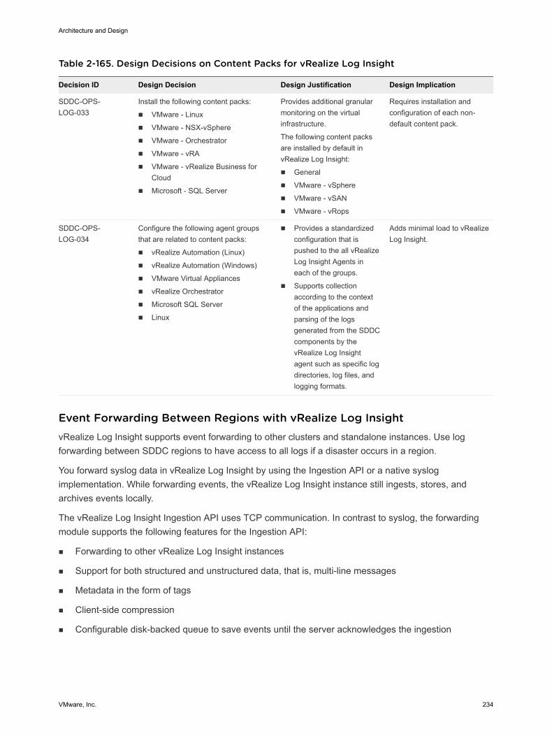
Table 2-165. Design Decisions on Content Packs for vRealize Log Insight
Decision ID Design Decision Design Justification Design Implication
SDDC-OPS-LOG-033
Install the following content packs:
n VMware - Linux
n VMware - NSX-vSphere
n VMware - Orchestrator
n VMware - vRA
n VMware - vRealize Business forCloud
n Microsoft - SQL Server
Provides additional granularmonitoring on the virtualinfrastructure.
The following content packsare installed by default invRealize Log Insight:
n General
n VMware - vSphere
n VMware - vSAN
n VMware - vRops
Requires installation andconfiguration of each non-default content pack.
SDDC-OPS-LOG-034
Configure the following agent groupsthat are related to content packs:
n vRealize Automation (Linux)
n vRealize Automation (Windows)
n VMware Virtual Appliances
n vRealize Orchestrator
n Microsoft SQL Server
n Linux
n Provides a standardizedconfiguration that ispushed to the all vRealizeLog Insight Agents ineach of the groups.
n Supports collectionaccording to the contextof the applications andparsing of the logsgenerated from the SDDCcomponents by thevRealize Log Insightagent such as specific logdirectories, log files, andlogging formats.
Adds minimal load to vRealizeLog Insight.
Event Forwarding Between Regions with vRealize Log Insight vRealize Log Insight supports event forwarding to other clusters and standalone instances. Use logforwarding between SDDC regions to have access to all logs if a disaster occurs in a region.
You forward syslog data in vRealize Log Insight by using the Ingestion API or a native syslogimplementation. While forwarding events, the vRealize Log Insight instance still ingests, stores, andarchives events locally.
The vRealize Log Insight Ingestion API uses TCP communication. In contrast to syslog, the forwardingmodule supports the following features for the Ingestion API:
n Forwarding to other vRealize Log Insight instances
n Support for both structured and unstructured data, that is, multi-line messages
n Metadata in the form of tags
n Client-side compression
n Configurable disk-backed queue to save events until the server acknowledges the ingestion
Architecture and Design
VMware, Inc. 234
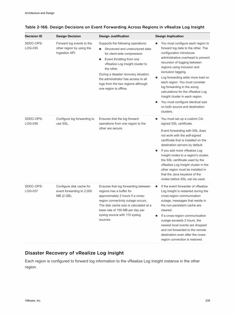
Table 2-166. Design Decisions on Event Forwarding Across Regions in vRealize Log Insight
Decision ID Design Decision Design Justification Design Implication
SDDC-OPS-LOG-035
Forward log events to theother region by using theIngestion API.
Supports the following operations:
n Structured and unstructured datafor client-side compression
n Event throttling from onevRealize Log Insight cluster tothe other.
During a disaster recovery situation,the administrator has access to alllogs from the two regions althoughone region is offline.
n You must configure each region toforward log data to the other. Theconfiguration introducesadministrative overhead to preventrecursion of logging betweenregions using inclusion andexclusion tagging.
n Log forwarding adds more load oneach region. You must considerlog forwarding in the sizingcalculations for the vRealize LogInsight cluster in each region.
n You must configure identical sizeon both source and destinationclusters.
SDDC-OPS-LOG-036
Configure log forwarding touse SSL.
Ensures that the log forwardoperations from one region to theother are secure.
n You must set up a custom CA-signed SSL certificate.
Event forwarding with SSL doesnot work with the self-signedcertificate that is installed on thedestination servers by default.
n If you add more vRealize LogInsight nodes to a region's cluster,the SSL certificate used by thevRealize Log Insight cluster in theother region must be installed inthat the Java keystore of thenodes before SSL can be used.
SDDC-OPS-LOG-037
Configure disk cache forevent forwarding to 2,000MB (2 GB).
Ensures that log forwarding betweenregions has a buffer forapproximately 2 hours if a cross-region connectivity outage occurs.The disk cache size is calculated at abase rate of 150 MB per day persyslog source with 110 syslogsources.
n If the event forwarder of vRealizeLog Insight is restarted during thecross-region communicationoutage, messages that reside inthe non-persistent cache arecleared.
n If a cross-region communicationoutage exceeds 2 hours, thenewest local events are droppedand not forwarded to the remotedestination even after the cross-region connection is restored.
Disaster Recovery of vRealize Log InsightEach region is configured to forward log information to the vRealize Log Insight instance in the otherregion.
Architecture and Design
VMware, Inc. 235
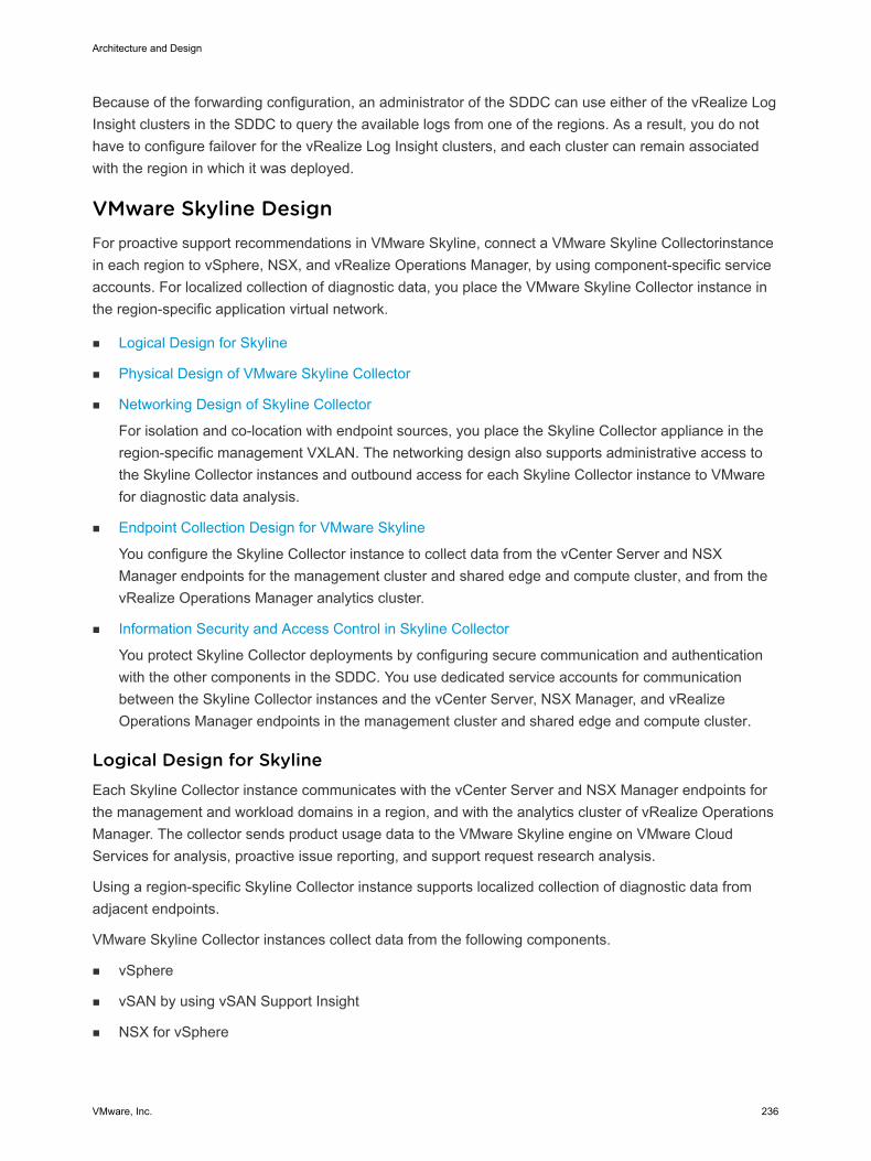
Because of the forwarding configuration, an administrator of the SDDC can use either of the vRealize LogInsight clusters in the SDDC to query the available logs from one of the regions. As a result, you do nothave to configure failover for the vRealize Log Insight clusters, and each cluster can remain associatedwith the region in which it was deployed.
VMware Skyline Design For proactive support recommendations in VMware Skyline, connect a VMware Skyline Collectorinstancein each region to vSphere, NSX, and vRealize Operations Manager, by using component-specific serviceaccounts. For localized collection of diagnostic data, you place the VMware Skyline Collector instance inthe region-specific application virtual network.
n Logical Design for Skyline
n Physical Design of VMware Skyline Collector
n Networking Design of Skyline Collector
For isolation and co-location with endpoint sources, you place the Skyline Collector appliance in theregion-specific management VXLAN. The networking design also supports administrative access tothe Skyline Collector instances and outbound access for each Skyline Collector instance to VMwarefor diagnostic data analysis.
n Endpoint Collection Design for VMware Skyline
You configure the Skyline Collector instance to collect data from the vCenter Server and NSXManager endpoints for the management cluster and shared edge and compute cluster, and from thevRealize Operations Manager analytics cluster.
n Information Security and Access Control in Skyline Collector
You protect Skyline Collector deployments by configuring secure communication and authenticationwith the other components in the SDDC. You use dedicated service accounts for communicationbetween the Skyline Collector instances and the vCenter Server, NSX Manager, and vRealizeOperations Manager endpoints in the management cluster and shared edge and compute cluster.
Logical Design for Skyline Each Skyline Collector instance communicates with the vCenter Server and NSX Manager endpoints forthe management and workload domains in a region, and with the analytics cluster of vRealize OperationsManager. The collector sends product usage data to the VMware Skyline engine on VMware CloudServices for analysis, proactive issue reporting, and support request research analysis.
Using a region-specific Skyline Collector instance supports localized collection of diagnostic data fromadjacent endpoints.
VMware Skyline Collector instances collect data from the following components.
n vSphere
n vSAN by using vSAN Support Insight
n NSX for vSphere
Architecture and Design
VMware, Inc. 236
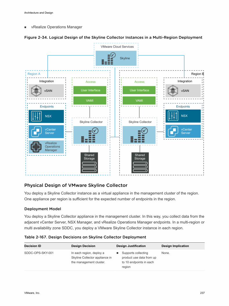
n vRealize Operations Manager
Figure 2-34. Logical Design of the Skyline Collector Instances in a Multi-Region Deployment
Region A
Endpoints
Skyline Collector
SharedStorage
NSX
vRealizeOperationsManager
Region B
Skyline Collector
Endpoints
Integration
vSAN
IntegrationAccess
User Interface
VAMI
Access
User Interface
VAMI
VMware Cloud Services
Skyline
NSX
vCenterServer
vSAN
vCenterServer
SharedStorage
Physical Design of VMware Skyline Collector You deploy a Skyline Collector instance as a virtual appliance in the management cluster of the region.One appliance per region is sufficient for the expected number of endpoints in the region.
Deployment Model
You deploy a Skyline Collector appliance in the management cluster. In this way, you collect data from theadjacent vCenter Server, NSX Manager, and vRealize Operations Manager endpoints. In a multi-region ormulti availability zone SDDC, you deploy a VMware Skyline Collector instance in each region.
Table 2-167. Design Decisions on Skyline Collector Deployment
Decision ID Design Decision Design Justification Design Implication
SDDC-OPS-SKY-001 In each region, deploy aSkyline Collector appliance inthe management cluster.
n Supports collectingproduct use data from upto 10 endpoints in eachregion
None.
Architecture and Design
VMware, Inc. 237
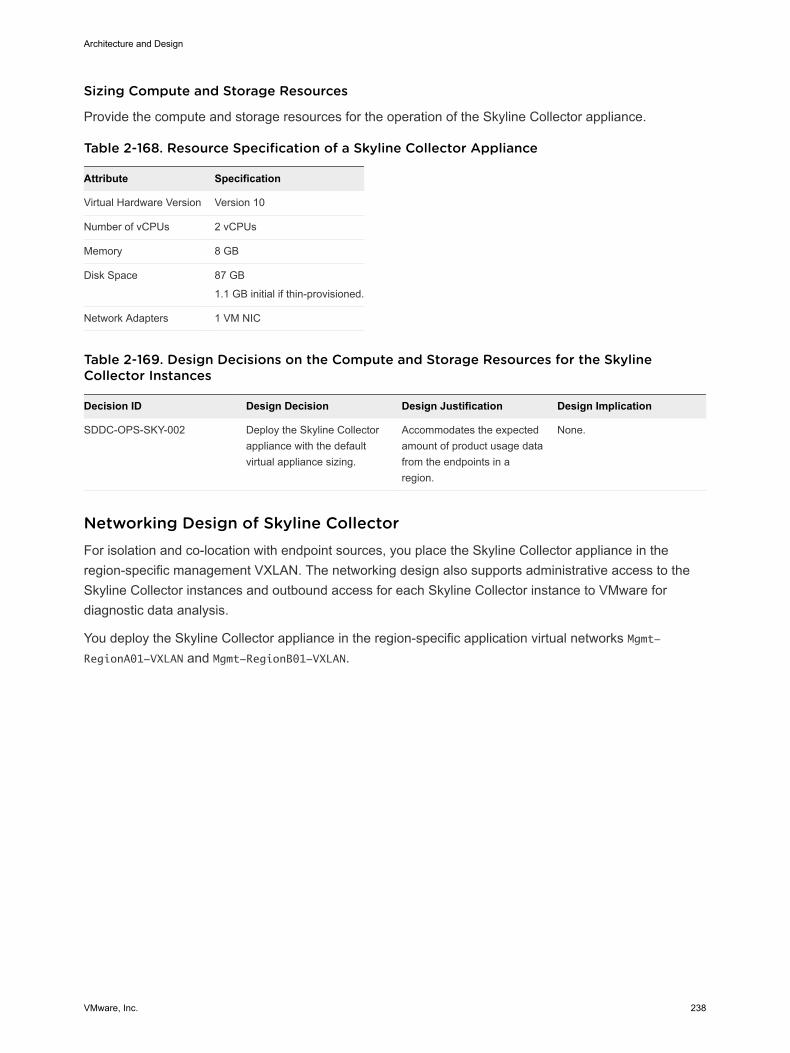
Sizing Compute and Storage Resources
Provide the compute and storage resources for the operation of the Skyline Collector appliance.
Table 2-168. Resource Specification of a Skyline Collector Appliance
Attribute Specification
Virtual Hardware Version Version 10
Number of vCPUs 2 vCPUs
Memory 8 GB
Disk Space 87 GB
1.1 GB initial if thin-provisioned.
Network Adapters 1 VM NIC
Table 2-169. Design Decisions on the Compute and Storage Resources for the SkylineCollector Instances
Decision ID Design Decision Design Justification Design Implication
SDDC-OPS-SKY-002 Deploy the Skyline Collectorappliance with the defaultvirtual appliance sizing.
Accommodates the expectedamount of product usage datafrom the endpoints in aregion.
None.
Networking Design of Skyline Collector For isolation and co-location with endpoint sources, you place the Skyline Collector appliance in theregion-specific management VXLAN. The networking design also supports administrative access to theSkyline Collector instances and outbound access for each Skyline Collector instance to VMware fordiagnostic data analysis.
You deploy the Skyline Collector appliance in the region-specific application virtual networks Mgmt-RegionA01-VXLAN and Mgmt-RegionB01-VXLAN.
Architecture and Design
VMware, Inc. 238
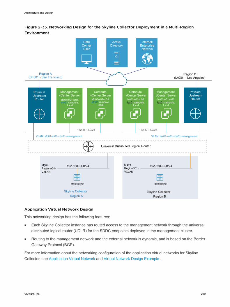
Figure 2-35. Networking Design for the Skyline Collector Deployment in a Multi-RegionEnvironment
APP
OS
Region B
APP
OS
DataCenterUser
ActiveDirectory
Internet/EnterpriseNetwork
Region A(SF001 - San Francisco)
Management vCenter Serverlax01m01vc01.lax01.rainpole.
local
Compute vCenter Serverlax01w01vc01.lax01.rainpole.
local
172.16.11.0/24 172.17.11.0/24
Management vCenter Server
sfo01m01vc01.sfo01.rainpole.
local
Compute vCenter Serversfo01w01vc01.sfo01.rainpole.
local
PhysicalUpstream
Router
Region B(LAX01 - Los Angeles)
PhysicalUpstream
Router
Mgmt-RegionB01-VXLAN
Skyline Collector
192.168.31.0/24Mgmt-RegionA01-VXLAN
Skyline CollectorRegion A
Universal Distributed Logical Router
VLAN: sfo01-m01-vds01-management VLAN: lax01-m01-vds01-management
sfo01sky01
192.168.32.0/24
lax01sky01
Application Virtual Network Design
This networking design has the following features:
n Each Skyline Collector instance has routed access to the management network through the universaldistributed logical router (UDLR) for the SDDC endpoints deployed in the management cluster.
n Routing to the management network and the external network is dynamic, and is based on the BorderGateway Protocol (BGP).
For more information about the networking configuration of the application virtual networks for SkylineCollector, see Application Virtual Network and Virtual Network Design Example .
Architecture and Design
VMware, Inc. 239
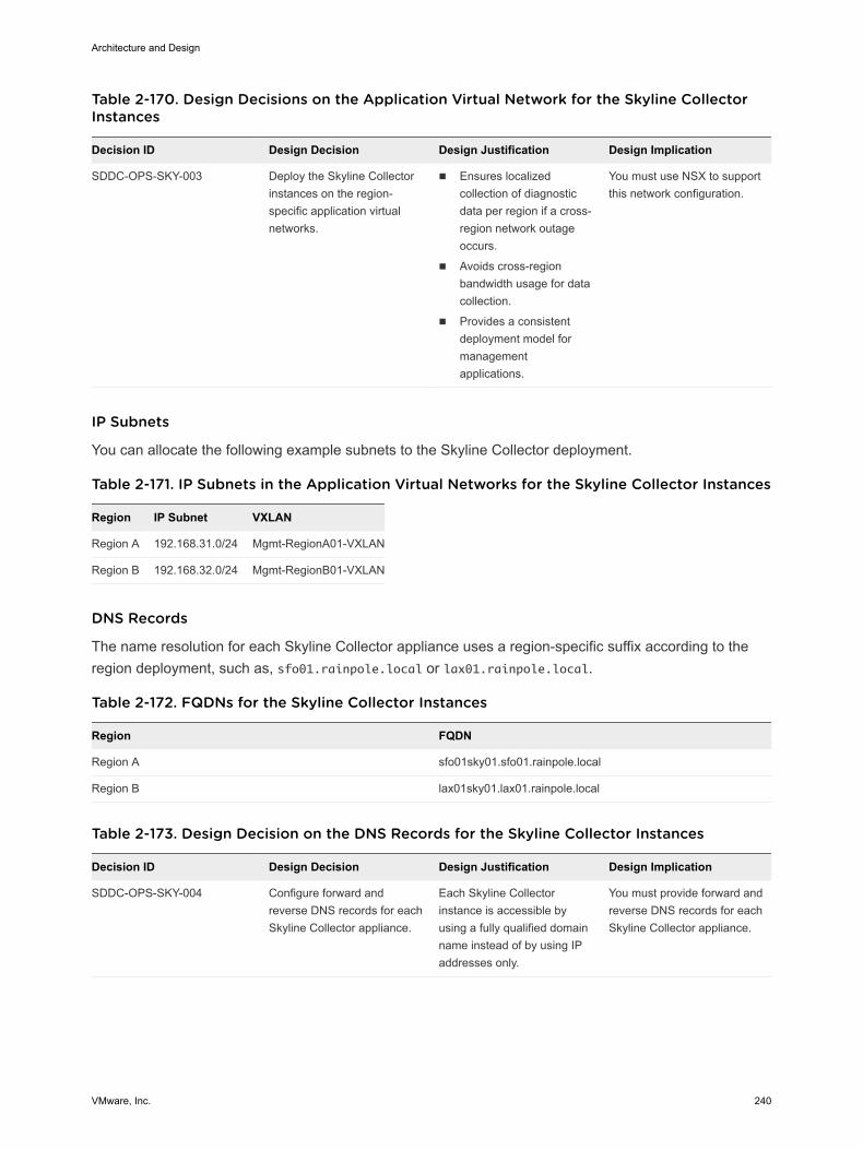
Table 2-170. Design Decisions on the Application Virtual Network for the Skyline CollectorInstances
Decision ID Design Decision Design Justification Design Implication
SDDC-OPS-SKY-003 Deploy the Skyline Collectorinstances on the region-specific application virtualnetworks.
n Ensures localizedcollection of diagnosticdata per region if a cross-region network outageoccurs.
n Avoids cross-regionbandwidth usage for datacollection.
n Provides a consistentdeployment model formanagementapplications.
You must use NSX to supportthis network configuration.
IP Subnets
You can allocate the following example subnets to the Skyline Collector deployment.
Table 2-171. IP Subnets in the Application Virtual Networks for the Skyline Collector Instances
Region IP Subnet VXLAN
Region A 192.168.31.0/24 Mgmt-RegionA01-VXLAN
Region B 192.168.32.0/24 Mgmt-RegionB01-VXLAN
DNS Records
The name resolution for each Skyline Collector appliance uses a region-specific suffix according to theregion deployment, such as, sfo01.rainpole.local or lax01.rainpole.local.
Table 2-172. FQDNs for the Skyline Collector Instances
Region FQDN
Region A sfo01sky01.sfo01.rainpole.local
Region B lax01sky01.lax01.rainpole.local
Table 2-173. Design Decision on the DNS Records for the Skyline Collector Instances
Decision ID Design Decision Design Justification Design Implication
SDDC-OPS-SKY-004 Configure forward andreverse DNS records for eachSkyline Collector appliance.
Each Skyline Collectorinstance is accessible byusing а fully qualified domainname instead of by using IPaddresses only.
You must provide forward andreverse DNS records for eachSkyline Collector appliance.
Architecture and Design
VMware, Inc. 240
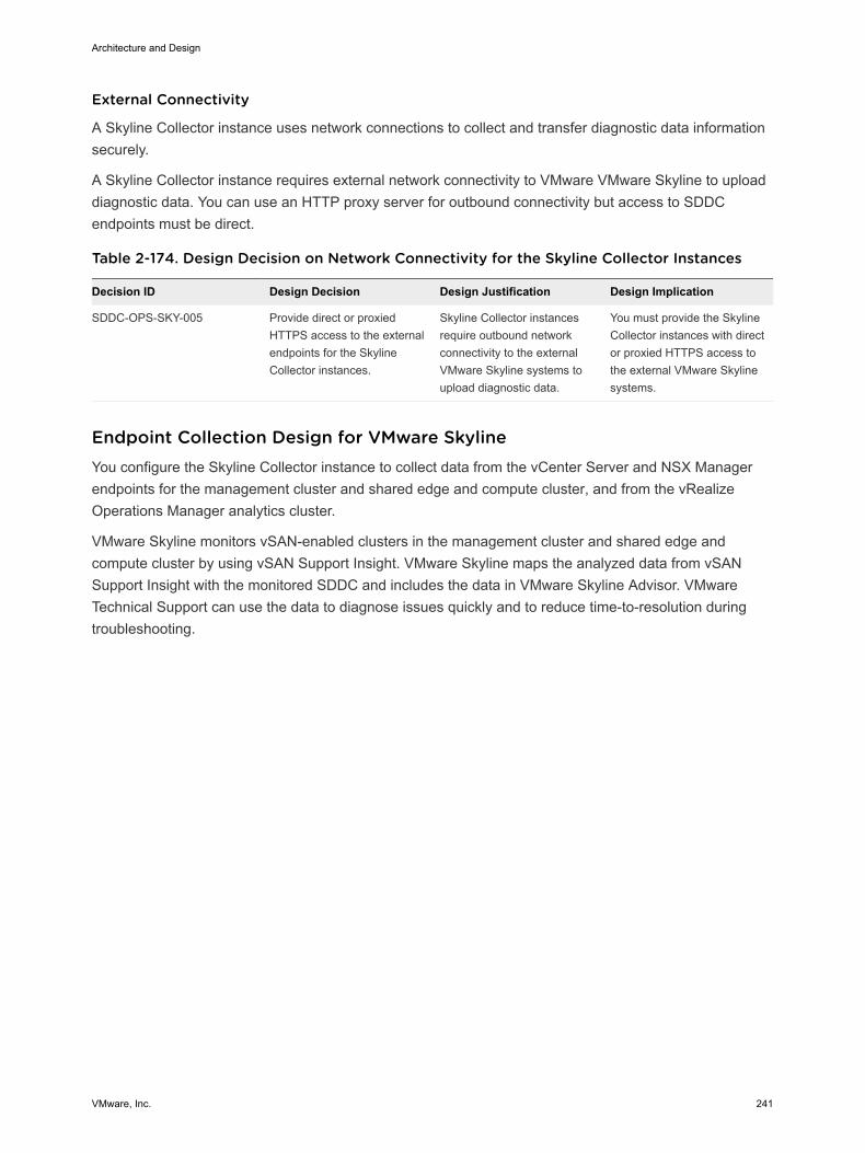
External Connectivity
A Skyline Collector instance uses network connections to collect and transfer diagnostic data informationsecurely.
A Skyline Collector instance requires external network connectivity to VMware VMware Skyline to uploaddiagnostic data. You can use an HTTP proxy server for outbound connectivity but access to SDDCendpoints must be direct.
Table 2-174. Design Decision on Network Connectivity for the Skyline Collector Instances
Decision ID Design Decision Design Justification Design Implication
SDDC-OPS-SKY-005 Provide direct or proxiedHTTPS access to the externalendpoints for the SkylineCollector instances.
Skyline Collector instancesrequire outbound networkconnectivity to the externalVMware Skyline systems toupload diagnostic data.
You must provide the SkylineCollector instances with director proxied HTTPS access tothe external VMware Skylinesystems.
Endpoint Collection Design for VMware Skyline You configure the Skyline Collector instance to collect data from the vCenter Server and NSX Managerendpoints for the management cluster and shared edge and compute cluster, and from the vRealizeOperations Manager analytics cluster.
VMware Skyline monitors vSAN-enabled clusters in the management cluster and shared edge andcompute cluster by using vSAN Support Insight. VMware Skyline maps the analyzed data from vSANSupport Insight with the monitored SDDC and includes the data in VMware Skyline Advisor. VMwareTechnical Support can use the data to diagnose issues quickly and to reduce time-to-resolution duringtroubleshooting.
Architecture and Design
VMware, Inc. 241
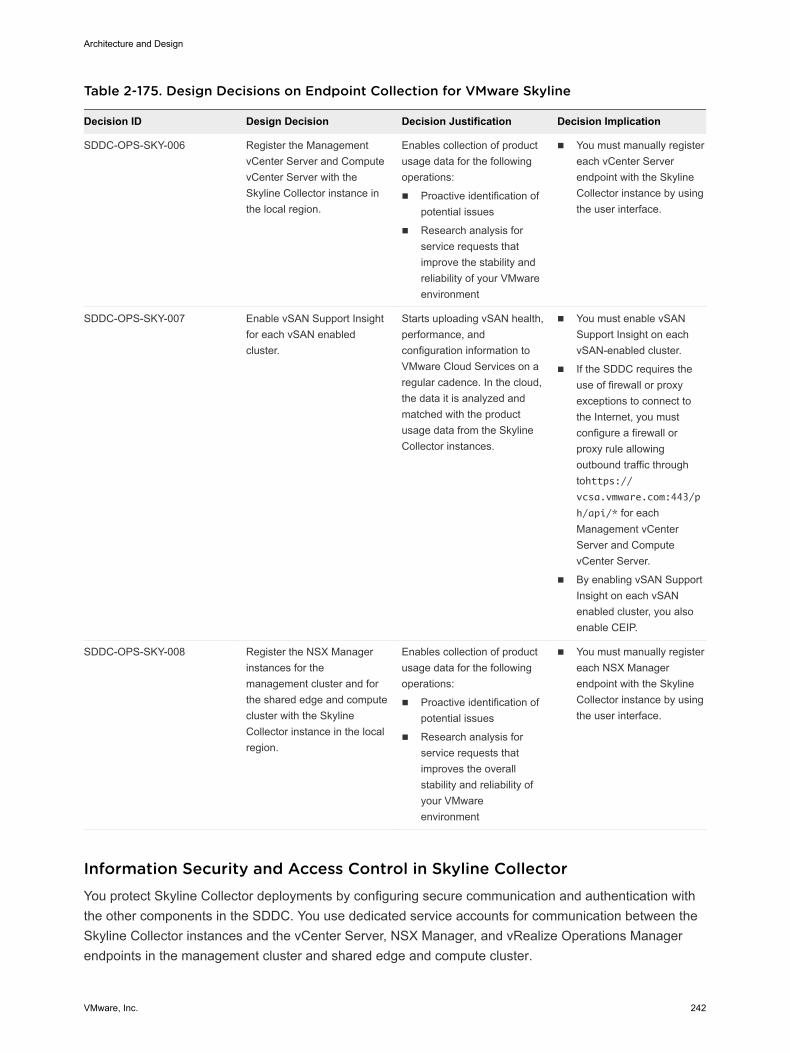
Table 2-175. Design Decisions on Endpoint Collection for VMware Skyline
Decision ID Design Decision Decision Justification Decision Implication
SDDC-OPS-SKY-006 Register the ManagementvCenter Server and ComputevCenter Server with theSkyline Collector instance inthe local region.
Enables collection of productusage data for the followingoperations:
n Proactive identification ofpotential issues
n Research analysis forservice requests thatimprove the stability andreliability of your VMwareenvironment
n You must manually registereach vCenter Serverendpoint with the SkylineCollector instance by usingthe user interface.
SDDC-OPS-SKY-007 Enable vSAN Support Insightfor each vSAN enabledcluster.
Starts uploading vSAN health,performance, andconfiguration information toVMware Cloud Services on aregular cadence. In the cloud,the data it is analyzed andmatched with the productusage data from the SkylineCollector instances.
n You must enable vSANSupport Insight on eachvSAN-enabled cluster.
n If the SDDC requires theuse of firewall or proxyexceptions to connect tothe Internet, you mustconfigure a firewall orproxy rule allowingoutbound traffic throughtohttps://vcsa.vmware.com:443/p
h/api/* for eachManagement vCenterServer and ComputevCenter Server.
n By enabling vSAN SupportInsight on each vSANenabled cluster, you alsoenable CEIP.
SDDC-OPS-SKY-008 Register the NSX Managerinstances for themanagement cluster and forthe shared edge and computecluster with the SkylineCollector instance in the localregion.
Enables collection of productusage data for the followingoperations:
n Proactive identification ofpotential issues
n Research analysis forservice requests thatimproves the overallstability and reliability ofyour VMwareenvironment
n You must manually registereach NSX Managerendpoint with the SkylineCollector instance by usingthe user interface.
Information Security and Access Control in Skyline Collector You protect Skyline Collector deployments by configuring secure communication and authentication withthe other components in the SDDC. You use dedicated service accounts for communication between theSkyline Collector instances and the vCenter Server, NSX Manager, and vRealize Operations Managerendpoints in the management cluster and shared edge and compute cluster.
Architecture and Design
VMware, Inc. 242
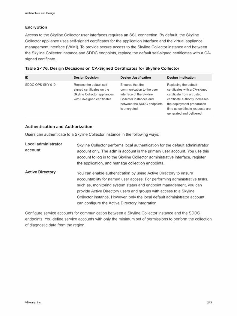
Encryption
Access to the Skyline Collector user interfaces requires an SSL connection. By default, the SkylineCollector appliance uses self-signed certificates for the application interface and the virtual appliancemanagement interface (VAMI). To provide secure access to the Skyline Collector instance and betweenthe Skyline Collector instance and SDDC endpoints, replace the default self-signed certificates with a CA-signed certificate.
Table 2-176. Design Decisions on CA-Signed Certificates for Skyline Collector
ID Design Decision Design Justification Design Implication
SDDC-OPS-SKY-010 Replace the default self-signed certificates on theSkyline Collector applianceswith CA-signed certificates.
Ensures that thecommunication to the userinterface of the SkylineCollector instances andbetween the SDDC endpointsis encrypted.
Replacing the defaultcertificates with a CA-signedcertificate from a trustedcertificate authority increasesthe deployment preparationtime as certificate requests aregenerated and delivered.
Authentication and Authorization
Users can authenticate to a Skyline Collector instance in the following ways:
Local administratoraccount
Skyline Collector performs local authentication for the default administratoraccount only. The admin account is the primary user account. You use thisaccount to log in to the Skyline Collector administrative interface, registerthe application, and manage collection endpoints.
Active Directory You can enable authentication by using Active Directory to ensureaccountability for named user access. For performing administrative tasks,such as, monitoring system status and endpoint management, you canprovide Active Directory users and groups with access to a SkylineCollector instance. However, only the local default administrator accountcan configure the Active Directory integration.
Configure service accounts for communication between a Skyline Collector instance and the SDDCendpoints. You define service accounts with only the minimum set of permissions to perform the collectionof diagnostic data from the region.
Architecture and Design
VMware, Inc. 243
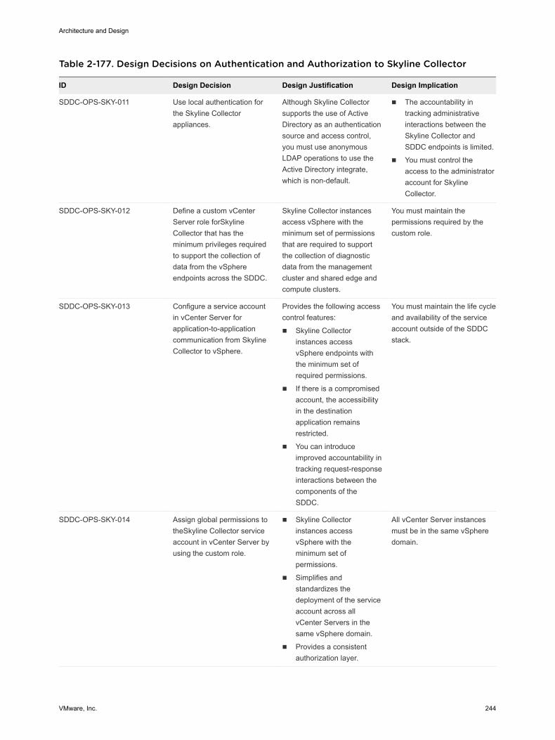
Table 2-177. Design Decisions on Authentication and Authorization to Skyline Collector
ID Design Decision Design Justification Design Implication
SDDC-OPS-SKY-011 Use local authentication forthe Skyline Collectorappliances.
Although Skyline Collectorsupports the use of ActiveDirectory as an authenticationsource and access control,you must use anonymousLDAP operations to use theActive Directory integrate,which is non-default.
n The accountability intracking administrativeinteractions between theSkyline Collector andSDDC endpoints is limited.
n You must control theaccess to the administratoraccount for SkylineCollector.
SDDC-OPS-SKY-012 Define a custom vCenterServer role forSkylineCollector that has theminimum privileges requiredto support the collection ofdata from the vSphereendpoints across the SDDC.
Skyline Collector instancesaccess vSphere with theminimum set of permissionsthat are required to supportthe collection of diagnosticdata from the managementcluster and shared edge andcompute clusters.
You must maintain thepermissions required by thecustom role.
SDDC-OPS-SKY-013 Configure a service accountin vCenter Server forapplication-to-applicationcommunication from SkylineCollector to vSphere.
Provides the following accesscontrol features:
n Skyline Collectorinstances accessvSphere endpoints withthe minimum set ofrequired permissions.
n If there is a compromisedaccount, the accessibilityin the destinationapplication remainsrestricted.
n You can introduceimproved accountability intracking request-responseinteractions between thecomponents of theSDDC.
You must maintain the life cycleand availability of the serviceaccount outside of the SDDCstack.
SDDC-OPS-SKY-014 Assign global permissions totheSkyline Collector serviceaccount in vCenter Server byusing the custom role.
n Skyline Collectorinstances accessvSphere with theminimum set ofpermissions.
n Simplifies andstandardizes thedeployment of the serviceaccount across allvCenter Servers in thesame vSphere domain.
n Provides a consistentauthorization layer.
All vCenter Server instancesmust be in the same vSpheredomain.
Architecture and Design
VMware, Inc. 244
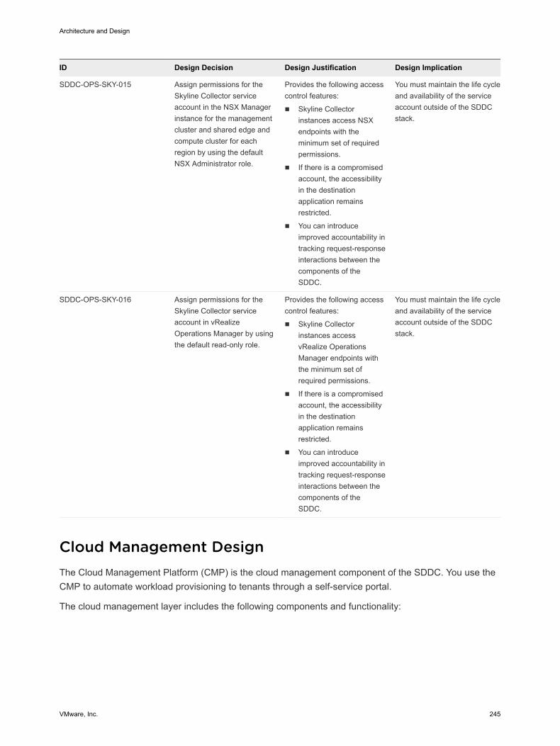
ID Design Decision Design Justification Design Implication
SDDC-OPS-SKY-015 Assign permissions for theSkyline Collector serviceaccount in the NSX Managerinstance for the managementcluster and shared edge andcompute cluster for eachregion by using the defaultNSX Administrator role.
Provides the following accesscontrol features:
n Skyline Collectorinstances access NSXendpoints with theminimum set of requiredpermissions.
n If there is a compromisedaccount, the accessibilityin the destinationapplication remainsrestricted.
n You can introduceimproved accountability intracking request-responseinteractions between thecomponents of theSDDC.
You must maintain the life cycleand availability of the serviceaccount outside of the SDDCstack.
SDDC-OPS-SKY-016 Assign permissions for theSkyline Collector serviceaccount in vRealizeOperations Manager by usingthe default read-only role.
Provides the following accesscontrol features:
n Skyline Collectorinstances accessvRealize OperationsManager endpoints withthe minimum set ofrequired permissions.
n If there is a compromisedaccount, the accessibilityin the destinationapplication remainsrestricted.
n You can introduceimproved accountability intracking request-responseinteractions between thecomponents of theSDDC.
You must maintain the life cycleand availability of the serviceaccount outside of the SDDCstack.
Cloud Management Design The Cloud Management Platform (CMP) is the cloud management component of the SDDC. You use theCMP to automate workload provisioning to tenants through a self-service portal.
The cloud management layer includes the following components and functionality:
Architecture and Design
VMware, Inc. 245
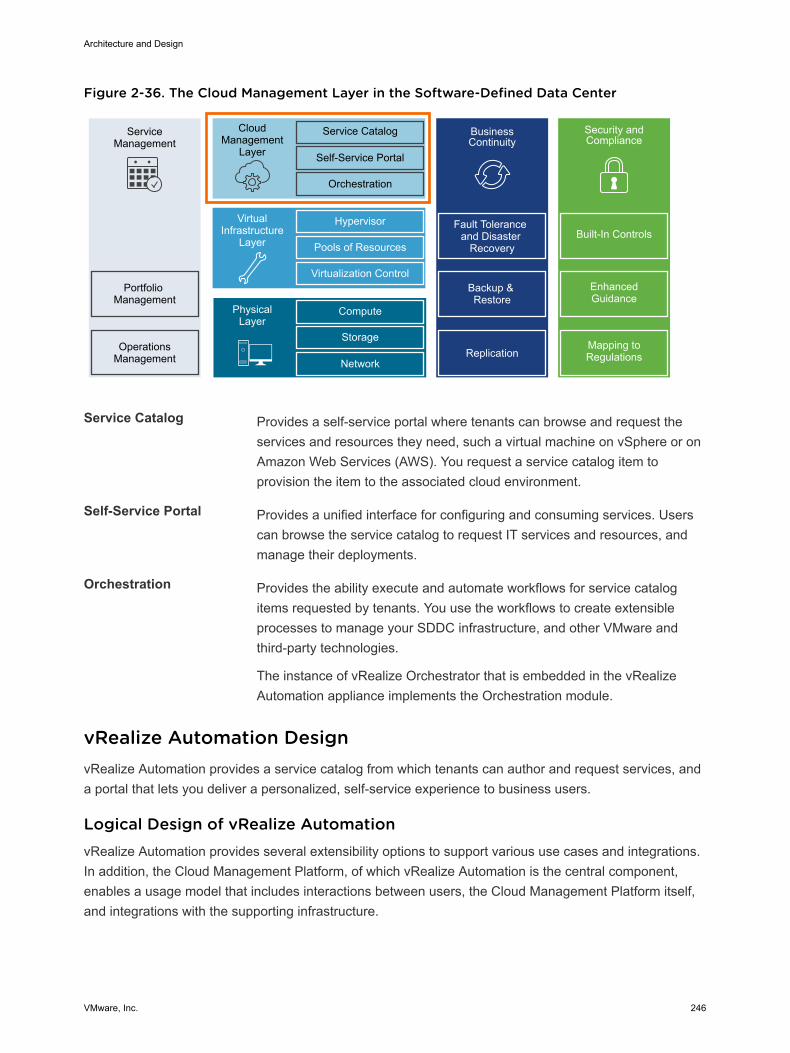
Figure 2-36. The Cloud Management Layer in the Software-Defined Data Center
ServiceManagement
Portfolio Management
OperationsManagement
CloudManagement
Layer
Service Catalog
Self-Service Portal
Orchestration
BusinessContinuity
Fault Tolerance and Disaster
Recovery
Backup & Restore
Hypervisor
Pools of Resources
Virtualization Control
VirtualInfrastructure
Layer
Compute
Storage
Network
PhysicalLayer
Replication
Security and Compliance
Mapping to Regulations
Enhanced Guidance
Built-In Controls
Service Catalog Provides a self-service portal where tenants can browse and request theservices and resources they need, such a virtual machine on vSphere or onAmazon Web Services (AWS). You request a service catalog item toprovision the item to the associated cloud environment.
Self-Service Portal Provides a unified interface for configuring and consuming services. Userscan browse the service catalog to request IT services and resources, andmanage their deployments.
Orchestration Provides the ability execute and automate workflows for service catalogitems requested by tenants. You use the workflows to create extensibleprocesses to manage your SDDC infrastructure, and other VMware andthird-party technologies.
The instance of vRealize Orchestrator that is embedded in the vRealizeAutomation appliance implements the Orchestration module.
vRealize Automation Design vRealize Automation provides a service catalog from which tenants can author and request services, anda portal that lets you deliver a personalized, self-service experience to business users.
Logical Design of vRealize AutomationvRealize Automation provides several extensibility options to support various use cases and integrations.In addition, the Cloud Management Platform, of which vRealize Automation is the central component,enables a usage model that includes interactions between users, the Cloud Management Platform itself,and integrations with the supporting infrastructure.
Architecture and Design
VMware, Inc. 246
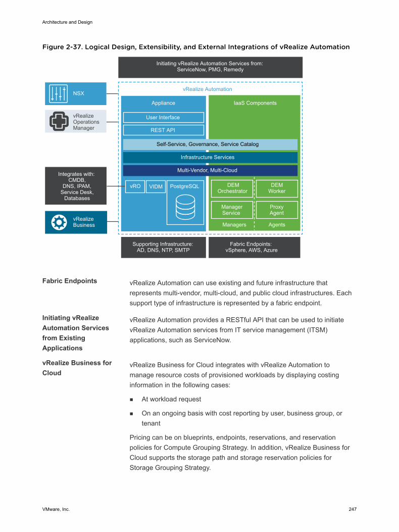
Figure 2-37. Logical Design, Extensibility, and External Integrations of vRealize Automation
PostgreSQL vRO VIDM
Initiating vRealize Automation Services from: ServiceNow, PMG, Remedy
Supporting Infrastructure: AD, DNS, NTP, SMTP
Fabric Endpoints: vSphere, AWS, Azure
ProxyAgent
vRealize Automation
Appliance
User Interface
IaaS Components
DEMOrchestrator
DEMWorker
ManagerService
Managers Agents
REST API
vRealizeBusiness
vRealizeOperationsManager
Self-Service, Governance, Service Catalog
Infrastructure Services
Multi-Vendor, Multi-CloudIntegrates with:
CMDB,DNS, IPAM,
Service Desk, Databases
NSX
Fabric Endpoints vRealize Automation can use existing and future infrastructure thatrepresents multi-vendor, multi-cloud, and public cloud infrastructures. Eachsupport type of infrastructure is represented by a fabric endpoint.
Initiating vRealizeAutomation Servicesfrom ExistingApplications
vRealize Automation provides a RESTful API that can be used to initiatevRealize Automation services from IT service management (ITSM)applications, such as ServiceNow.
vRealize Business forCloud
vRealize Business for Cloud integrates with vRealize Automation tomanage resource costs of provisioned workloads by displaying costinginformation in the following cases:
n At workload request
n On an ongoing basis with cost reporting by user, business group, ortenant
Pricing can be on blueprints, endpoints, reservations, and reservationpolicies for Compute Grouping Strategy. In addition, vRealize Business forCloud supports the storage path and storage reservation policies forStorage Grouping Strategy.
Architecture and Design
VMware, Inc. 247
vRealize OperationsManager
The vRealize Operations management pack for vRealize Automationprovides performance and capacity metrics of tenant business groups andunderlying cloud infrastructure.
SupportingInfrastructure
vRealize Automation integrates with the following supporting infrastructure:
n A Microsoft SQL Server to store data relating to the vRealizeAutomation IaaS elements.
n NTP servers for time synchronization between the vRealize Automationcomponents.
n Active Directory for tenant user authentication and authorization.
n SMTP for sending and receiving notification emails for various actionsthat can be run in the vRealize Automation console.
NSX The integration of vRealize Automation with NSX supports designing andauthoring blueprints by using the networking and security features of NSX.You can use all NSX network constructs, such as logical switches,distributed logical routing, and distributed firewalls.
In a blueprint, you can place an on-demand load balancer, NAT network,routed network, and security groups. When a user requests the blueprint,vRealize Automation automatically provisions these constructs in NSX.
You can configure automated network provisioning as a part of the blueprintdesign instead of as a separate operation outside vRealize Automation.
Cloud Management Platform Usage Model
The Cloud Management Platform, of which vRealize Automation is a central component, enables a usagemodel that includes interaction between users, the platform itself, the supporting infrastructure, and theprovisioning infrastructure.
Architecture and Design
VMware, Inc. 248
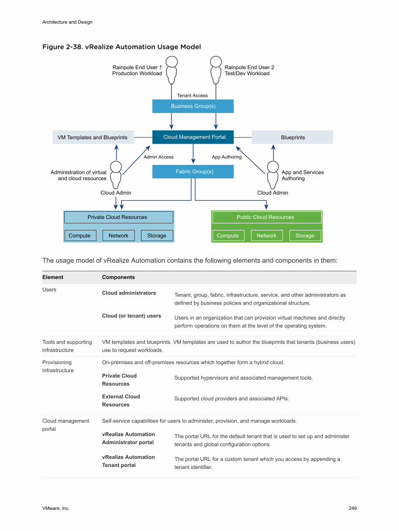
Figure 2-38. vRealize Automation Usage Model
Compute
Business Group(s)
Rainpole End User 1Production Workload
Rainpole End User 2Test/Dev Workload
Fabric Group(s)
Cloud Management PortalVM Templates and Blueprints
Tenant Access
Administration of virtualand cloud resources
Private Cloud Resources
Network Storage Compute
Public Cloud Resources
Network Storage
Cloud Admin
Admin Access
Blueprints
App and ServicesAuthoring
Cloud Admin
App Authoring
The usage model of vRealize Automation contains the following elements and components in them:
Element Components
Users Cloud administrators Tenant, group, fabric, infrastructure, service, and other administrators asdefined by business policies and organizational structure.
Cloud (or tenant) users Users in an organization that can provision virtual machines and directlyperform operations on them at the level of the operating system.
Tools and supportinginfrastructure
VM templates and blueprints. VM templates are used to author the blueprints that tenants (business users)use to request workloads.
Provisioninginfrastructure
On-premises and off-premises resources which together form a hybrid cloud.
Private CloudResources
Supported hypervisors and associated management tools.
External CloudResources
Supported cloud providers and associated APIs.
Cloud managementportal
Self-service capabilities for users to administer, provision, and manage workloads.
vRealize AutomationAdministrator portal
The portal URL for the default tenant that is used to set up and administertenants and global configuration options.
vRealize AutomationTenant portal
The portal URL for a custom tenant which you access by appending atenant identifier.
Architecture and Design
VMware, Inc. 249
Physical Design of vRealize Automation The physical design consists of characteristics and decisions that support the logical design. The designobjective is to deploy a fully functional cloud management portal with high availability and the ability toprovision to both Regions A and B.
To accomplish this design objective, you deploy or reuse the following components in Region A to createa cloud management portal of the SDDC.
n Three vRealize Automation appliances (embedded vRealize Orchestrator instances)
n Two vRealize Automation IaaS Web Server virtual machines
n Two vRealize Automation IaaS Manager Service virtual machines (including the DEM Orchestratorinstances)
n Two vRealize Automation IaaS DEM Server virtual machines
n Two vRealize Automation IaaS Proxy Agent virtual machines
n One vRealize Business appliance
n One vRealize Business Data Collector appliance
n Supporting infrastructure, such as Microsoft SQL Server, Active Directory, DNS, NTP, and SMTP.
You place the vRealize Automation components on specific virtual networks for isolation and failover.
Architecture and Design
VMware, Inc. 250
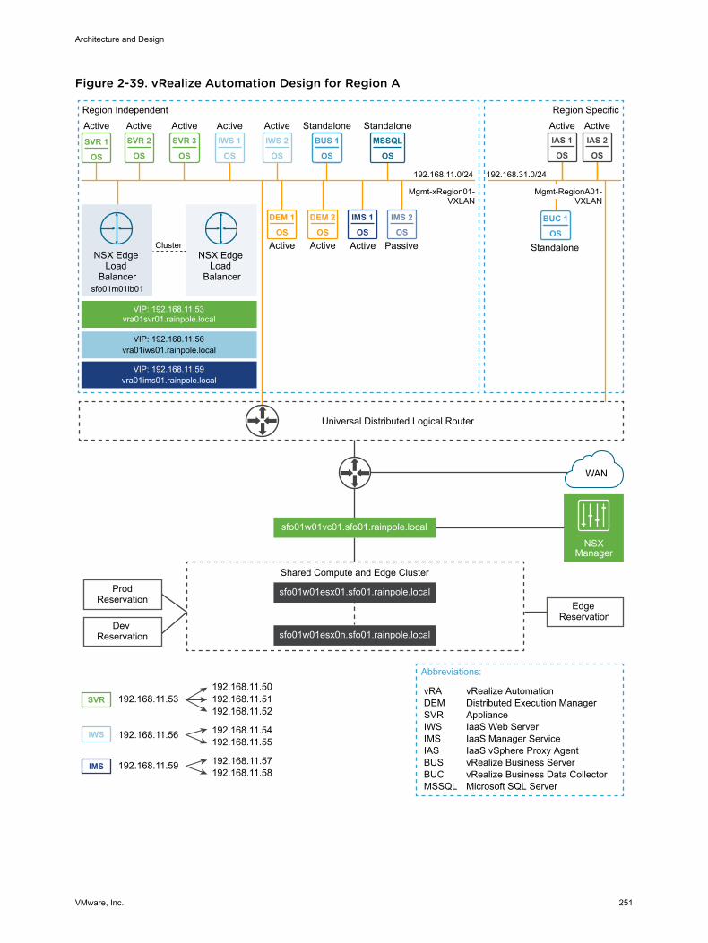
Figure 2-39. vRealize Automation Design for Region A
IWS 1
OS
MSSQL
OS
IMS 1
OS
DEM 1
OS
DEM 2
OS
SVR 2
OS
SVR 3
OS
IWS 2
OS
IAS 1
OS
IAS 2
OS
IWS
IMS
SVR
BUC 1
OS
BUS 1
OSSVR 1
OS
IMS 2
OS
Universal Distributed Logical Router
VIP: 192.168.11.53vra01svr01.rainpole.local
VIP: 192.168.11.56vra01iws01.rainpole.local
VIP: 192.168.11.59vra01ims01.rainpole.local
Active Active Standalone Standalone
Active PassiveActive Active
Active Active Active Active Active
Mgmt-xRegion01-VXLAN
Region Independent Region Specific
NSX Edge Load
Balancersfo01m01lb01
NSX Edge Load
Balancer
Cluster
Edge Reservation
WAN
Abbreviations:
vRA vRealize AutomationDEM Distributed Execution ManagerSVR ApplianceIWS IaaS Web ServerIMS IaaS Manager ServiceIAS IaaS vSphere Proxy AgentBUS vRealize Business ServerBUC vRealize Business Data CollectorMSSQL Microsoft SQL Server
sfo01w01vc01.sfo01.rainpole.local
sfo01w01esx01.sfo01.rainpole.local
sfo01w01esx0n.sfo01.rainpole.local
Shared Compute and Edge Cluster
NSXManager
Dev Reservation
ProdReservation
192.168.11.56 192.168.11.54192.168.11.55
192.168.11.59 192.168.11.57192.168.11.58
192.168.11.53 192.168.11.51192.168.11.50
192.168.11.52
Mgmt-RegionA01-VXLAN
Standalone
192.168.11.0/24 192.168.31.0/24
Architecture and Design
VMware, Inc. 251
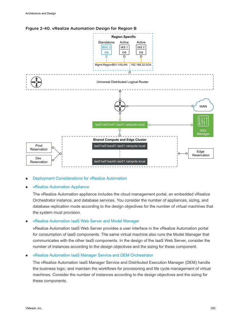
Figure 2-40. vRealize Automation Design for Region B
IAS 1
OS
IAS 2
OS
BUC 2
OS
Region Specific
Universal Distributed Logical Router
Active Active
Edge Reservation
WAN
lax01w01vc01.lax01.rainpole.local
lax01w01esx01.lax01.rainpole.local
lax01w01esx0n.lax01.rainpole.local
Shared Compute and Edge Cluster
NSXManager
Dev Reservation
ProdReservation
Mgmt-RegionB01-VXLAN
Standalone
192.168.32.0/24
n Deployment Considerations for vRealize Automation
n vRealize Automation Appliance
The vRealize Automation appliance includes the cloud management portal, an embedded vRealizeOrchestrator instance, and database services. You consider the number of appliances, sizing, anddatabase replication mode according to the design objectives for the number of virtual machines thatthe system must provision.
n vRealize Automation IaaS Web Server and Model Manager
vRealize Automation IaaS Web Server provides a user interface in the vRealize Automation portalfor consumption of IaaS components. The same virtual machine also runs the Model Manager thatcommunicates with the other IaaS components. In the design of the IaaS Web Server, consider thenumber of instances according to the design objectives and the sizing for these component.
n vRealize Automation IaaS Manager Service and DEM Orchestrator
The vRealize Automation IaaS Manager Service and Distributed Execution Manager (DEM) handlethe business logic, and maintain the workflows for provisioning and life cycle management of virtualmachines. Consider the number of instances according to the design objectives and the sizing forthese components.
Architecture and Design
VMware, Inc. 252
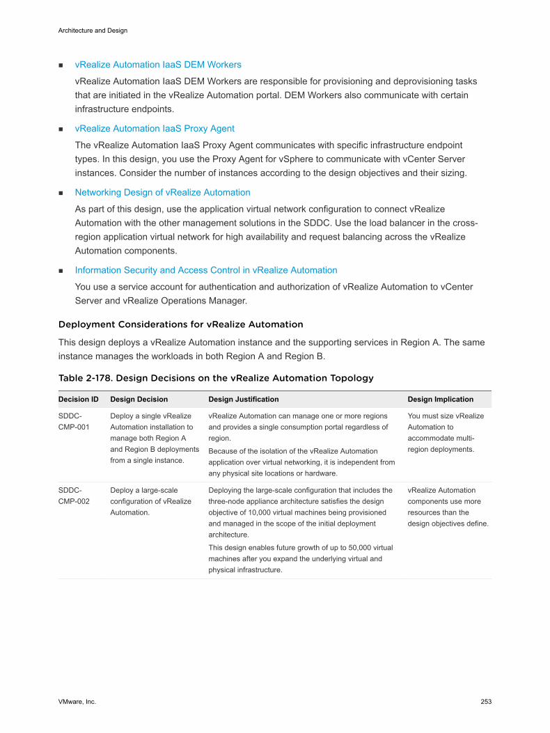
n vRealize Automation IaaS DEM Workers
vRealize Automation IaaS DEM Workers are responsible for provisioning and deprovisioning tasksthat are initiated in the vRealize Automation portal. DEM Workers also communicate with certaininfrastructure endpoints.
n vRealize Automation IaaS Proxy Agent
The vRealize Automation IaaS Proxy Agent communicates with specific infrastructure endpointtypes. In this design, you use the Proxy Agent for vSphere to communicate with vCenter Serverinstances. Consider the number of instances according to the design objectives and their sizing.
n Networking Design of vRealize Automation
As part of this design, use the application virtual network configuration to connect vRealizeAutomation with the other management solutions in the SDDC. Use the load balancer in the cross-region application virtual network for high availability and request balancing across the vRealizeAutomation components.
n Information Security and Access Control in vRealize Automation
You use a service account for authentication and authorization of vRealize Automation to vCenterServer and vRealize Operations Manager.
Deployment Considerations for vRealize Automation
This design deploys a vRealize Automation instance and the supporting services in Region A. The sameinstance manages the workloads in both Region A and Region B.
Table 2-178. Design Decisions on the vRealize Automation Topology
Decision ID Design Decision Design Justification Design Implication
SDDC-CMP-001
Deploy a single vRealizeAutomation installation tomanage both Region Aand Region B deploymentsfrom a single instance.
vRealize Automation can manage one or more regionsand provides a single consumption portal regardless ofregion.
Because of the isolation of the vRealize Automationapplication over virtual networking, it is independent fromany physical site locations or hardware.
You must size vRealizeAutomation toaccommodate multi-region deployments.
SDDC-CMP-002
Deploy a large-scaleconfiguration of vRealizeAutomation.
Deploying the large-scale configuration that includes thethree-node appliance architecture satisfies the designobjective of 10,000 virtual machines being provisionedand managed in the scope of the initial deploymentarchitecture.
This design enables future growth of up to 50,000 virtualmachines after you expand the underlying virtual andphysical infrastructure.
vRealize Automationcomponents use moreresources than thedesign objectives define.
Architecture and Design
VMware, Inc. 253
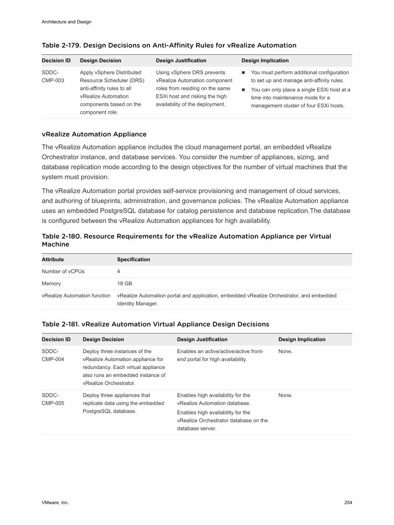
Table 2-179. Design Decisions on Anti-Affinity Rules for vRealize Automation
Decision ID Design Decision Design Justification Design Implication
SDDC-CMP-003
Apply vSphere DistributedResource Scheduler (DRS)anti-affinity rules to allvRealize Automationcomponents based on thecomponent role.
Using vSphere DRS preventsvRealize Automation componentroles from residing on the sameESXi host and risking the highavailability of the deployment.
n You must perform additional configurationto set up and manage anti-affinity rules.
n You can only place a single ESXi host at atime into maintenance mode for amanagement cluster of four ESXi hosts.
vRealize Automation Appliance
The vRealize Automation appliance includes the cloud management portal, an embedded vRealizeOrchestrator instance, and database services. You consider the number of appliances, sizing, anddatabase replication mode according to the design objectives for the number of virtual machines that thesystem must provision.
The vRealize Automation portal provides self-service provisioning and management of cloud services,and authoring of blueprints, administration, and governance policies. The vRealize Automation applianceuses an embedded PostgreSQL database for catalog persistence and database replication.The databaseis configured between the vRealize Automation appliances for high availability.
Table 2-180. Resource Requirements for the vRealize Automation Appliance per VirtualMachine
Attribute Specification
Number of vCPUs 4
Memory 18 GB
vRealize Automation function vRealize Automation portal and application, embedded vRealize Orchestrator, and embeddedIdentity Manager.
Table 2-181. vRealize Automation Virtual Appliance Design Decisions
Decision ID Design Decision Design Justification Design Implication
SDDC-CMP-004
Deploy three instances of thevRealize Automation appliance forredundancy. Each virtual appliancealso runs an embedded instance ofvRealize Orchestrator.
Enables an active/active/active front-end portal for high availability.
None.
SDDC-CMP-005
Deploy three appliances thatreplicate data using the embeddedPostgreSQL database.
Enables high availability for thevRealize Automation database.
Enables high availability for thevRealize Orchestrator database on thedatabase server.
None.
Architecture and Design
VMware, Inc. 254
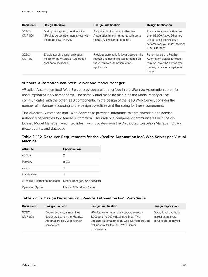
Decision ID Design Decision Design Justification Design Implication
SDDC-CMP-006
During deployment, configure thevRealize Automation appliances withthe default 18 GB RAM.
Supports deployment of vRealizeAutomation in environments with up to95,000 Active Directory users.
For environments with morethan 95,000 Active Directoryusers synced to vRealizeAutomation, you must increaseto 30 GB RAM.
SDDC-CMP-007
Enable synchronous replicationmode for the vRealize Automationappliance database.
Provides automatic failover between themaster and active replica database onthe vRealize Automation virtualappliances.
Performance of vRealizeAutomation database clustermay be lower than when youuse asynchronous replicationmode.
vRealize Automation IaaS Web Server and Model Manager
vRealize Automation IaaS Web Server provides a user interface in the vRealize Automation portal forconsumption of IaaS components. The same virtual machine also runs the Model Manager thatcommunicates with the other IaaS components. In the design of the IaaS Web Server, consider thenumber of instances according to the design objectives and the sizing for these component.
The vRealize Automation IaaS Web Server site provides infrastructure administration and serviceauthoring capabilities to vRealize Automation. The Web site component communicates with the co-located Model Manager, which provides it with updates from the Distributed Execution Manager (DEM),proxy agents, and database.
Table 2-182. Resource Requirements for the vRealize Automation IaaS Web Server per VirtualMachine
Attribute Specification
vCPUs 2
Memory 8 GB
vNICs 1
Local drives 1
vRealize Automation functions Model Manager (Web service)
Operating System Microsoft Windows Server
Table 2-183. Design Decisions on vRealize Automation IaaS Web Server
Decision ID Design Decision Design Justification Design Implication
SDDC-CMP-008
Deploy two virtual machinesdesignated to run the vRealizeAutomation IaaS Web Servercomponent.
vRealize Automation can support between1,000 and 10,000 virtual machines. TwovRealize Automation IaaS Web Servers provideredundancy for the IaaS Web Servercomponents.
Operational overheadincreases as moreservers are deployed.
Architecture and Design
VMware, Inc. 255
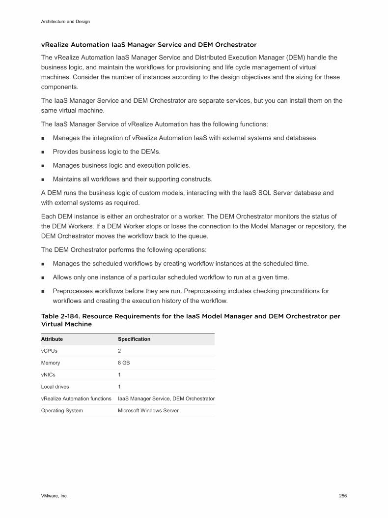
vRealize Automation IaaS Manager Service and DEM Orchestrator
The vRealize Automation IaaS Manager Service and Distributed Execution Manager (DEM) handle thebusiness logic, and maintain the workflows for provisioning and life cycle management of virtualmachines. Consider the number of instances according to the design objectives and the sizing for thesecomponents.
The IaaS Manager Service and DEM Orchestrator are separate services, but you can install them on thesame virtual machine.
The IaaS Manager Service оf vRealize Automation has the following functions:
n Manages the integration of vRealize Automation IaaS with external systems and databases.
n Provides business logic to the DEMs.
n Manages business logic and execution policies.
n Maintains all workflows and their supporting constructs.
A DEM runs the business logic of custom models, interacting with the IaaS SQL Server database andwith external systems as required.
Each DEM instance is either an orchestrator or a worker. The DEM Orchestrator monitors the status ofthe DEM Workers. If a DEM Worker stops or loses the connection to the Model Manager or repository, theDEM Orchestrator moves the workflow back to the queue.
The DEM Orchestrator performs the following operations:
n Manages the scheduled workflows by creating workflow instances at the scheduled time.
n Allows only one instance of a particular scheduled workflow to run at a given time.
n Preprocesses workflows before they are run. Preprocessing includes checking preconditions forworkflows and creating the execution history of the workflow.
Table 2-184. Resource Requirements for the IaaS Model Manager and DEM Orchestrator perVirtual Machine
Attribute Specification
vCPUs 2
Memory 8 GB
vNICs 1
Local drives 1
vRealize Automation functions IaaS Manager Service, DEM Orchestrator
Operating System Microsoft Windows Server
Architecture and Design
VMware, Inc. 256
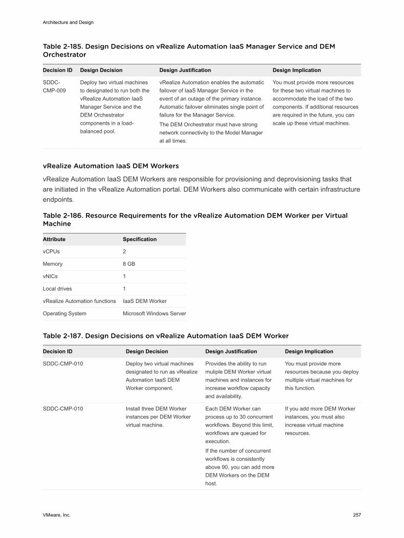
Table 2-185. Design Decisions on vRealize Automation IaaS Manager Service and DEMOrchestrator
Decision ID Design Decision Design Justification Design Implication
SDDC-CMP-009
Deploy two virtual machinesto designated to run both thevRealize Automation IaaSManager Service and theDEM Orchestratorcomponents in a load-balanced pool.
vRealize Automation enables the automaticfailover of IaaS Manager Service in theevent of an outage of the primary instance.Automatic failover eliminates single point offailure for the Manager Service.
The DEM Orchestrator must have strongnetwork connectivity to the Model Managerat all times.
You must provide more resourcesfor these two virtual machines toaccommodate the load of the twocomponents. If additional resourcesare required in the future, you canscale up these virtual machines.
vRealize Automation IaaS DEM Workers
vRealize Automation IaaS DEM Workers are responsible for provisioning and deprovisioning tasks thatare initiated in the vRealize Automation portal. DEM Workers also communicate with certain infrastructureendpoints.
Table 2-186. Resource Requirements for the vRealize Automation DEM Worker per VirtualMachine
Attribute Specification
vCPUs 2
Memory 8 GB
vNICs 1
Local drives 1
vRealize Automation functions IaaS DEM Worker
Operating System Microsoft Windows Server
Table 2-187. Design Decisions on vRealize Automation IaaS DEM Worker
Decision ID Design Decision Design Justification Design Implication
SDDC-CMP-010 Deploy two virtual machinesdesignated to run as vRealizeAutomation IaaS DEMWorker component.
Provides the ability to runmuliple DEM Worker virtualmachines and instances forincrease workflow capacityand availability.
You must provide moreresources because you deploymultiple virtual machines forthis function.
SDDC-CMP-010 Install three DEM Workerinstances per DEM Workervirtual machine.
Each DEM Worker canprocess up to 30 concurrentworkflows. Beyond this limit,workflows are queued forexecution.
If the number of concurrentworkflows is consistentlyabove 90, you can add moreDEM Workers on the DEMhost.
If you add more DEM Workerinstances, you must alsoincrease virtual machineresources.
Architecture and Design
VMware, Inc. 257
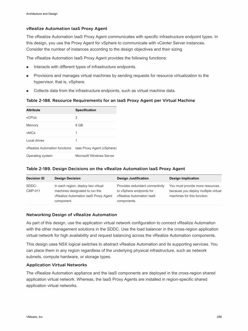
vRealize Automation IaaS Proxy Agent
The vRealize Automation IaaS Proxy Agent communicates with specific infrastructure endpoint types. Inthis design, you use the Proxy Agent for vSphere to communicate with vCenter Server instances.Consider the number of instances according to the design objectives and their sizing.
The vRealize Automation IaaS Proxy Agent provides the following functions:
n Interacts with different types of infrastructure endpoints.
n Provisions and manages virtual machines by sending requests for resource virtualization to thehypervisor, that is, vSphere.
n Collects data from the infrastructure endpoints, such as virtual machine data.
Table 2-188. Resource Requirements for an IaaS Proxy Agent per Virtual Machine
Attribute Specification
vCPUs 2
Memory 8 GB
vNICs 1
Local drives 1
vRealize Automation functions Iaas Proxy Agent (vSphere)
Operating system Microsoft Windows Server
Table 2-189. Design Decisions on the vRealize Automation IaaS Proxy Agent
Decision ID Design Decision Design Justification Design Implication
SDDC-CMP-011
In each region, deploy two virtualmachines designated to run thevRealize Automation IaaS Proxy Agentcomponent.
Provides redundant connectivityto vSphere endpoints forvRealize Automation IaaScomponents.
You must provide more resourcesbecause you deploy multiple virtualmachines for this function.
Networking Design of vRealize Automation
As part of this design, use the application virtual network configuration to connect vRealize Automationwith the other management solutions in the SDDC. Use the load balancer in the cross-region applicationvirtual network for high availability and request balancing across the vRealize Automation components.
This design uses NSX logical switches to abstract vRealize Automation and its supporting services. Youcan place them in any region regardless of the underlying physical infrastructure, such as networksubnets, compute hardware, or storage types.
Application Virtual Networks
The vRealize Automation appliance and the IaaS components are deployed in the cross-region sharedapplication virtual network. Whereas, the IaaS Proxy Agents are installed in region-specific sharedapplication virtual networks.
Architecture and Design
VMware, Inc. 258
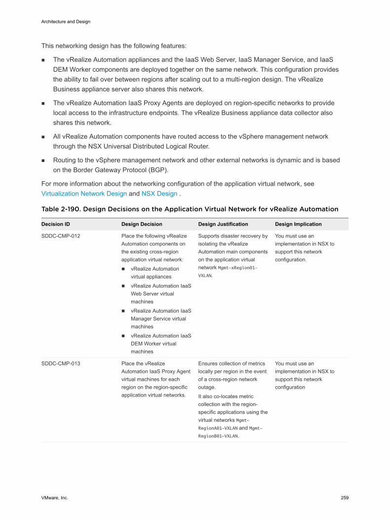
This networking design has the following features:
n The vRealize Automation appliances and the IaaS Web Server, IaaS Manager Service, and IaaSDEM Worker components are deployed together on the same network. This configuration providesthe ability to fail over between regions after scaling out to a multi-region design. The vRealizeBusiness appliance server also shares this network.
n The vRealize Automation IaaS Proxy Agents are deployed on region-specific networks to providelocal access to the infrastructure endpoints. The vRealize Business appliance data collector alsoshares this network.
n All vRealize Automation components have routed access to the vSphere management networkthrough the NSX Universal Distributed Logical Router.
n Routing to the vSphere management network and other external networks is dynamic and is basedon the Border Gateway Protocol (BGP).
For more information about the networking configuration of the application virtual network, seeVirtualization Network Design and NSX Design .
Table 2-190. Design Decisions on the Application Virtual Network for vRealize Automation
Decision ID Design Decision Design Justification Design Implication
SDDC-CMP-012 Place the following vRealizeAutomation components onthe existing cross-regionapplication virtual network:
n vRealize Automationvirtual appliances
n vRealize Automation IaaSWeb Server virtualmachines
n vRealize Automation IaaSManager Service virtualmachines
n vRealize Automation IaaSDEM Worker virtualmachines
Supports disaster recovery byisolating the vRealizeAutomation main componentson the application virtualnetwork Mgmt-xRegion01-VXLAN.
You must use animplementation in NSX tosupport this networkconfiguration.
SDDC-CMP-013 Place the vRealizeAutomation IaaS Proxy Agentvirtual machines for eachregion on the region-specificapplication virtual networks.
Ensures collection of metricslocally per region in the eventof a cross-region networkoutage.
It also co-locates metriccollection with the region-specific applications using thevirtual networks Mgmt-RegionA01-VXLAN and Mgmt-RegionB01-VXLAN.
You must use animplementation in NSX tosupport this networkconfiguration
Architecture and Design
VMware, Inc. 259
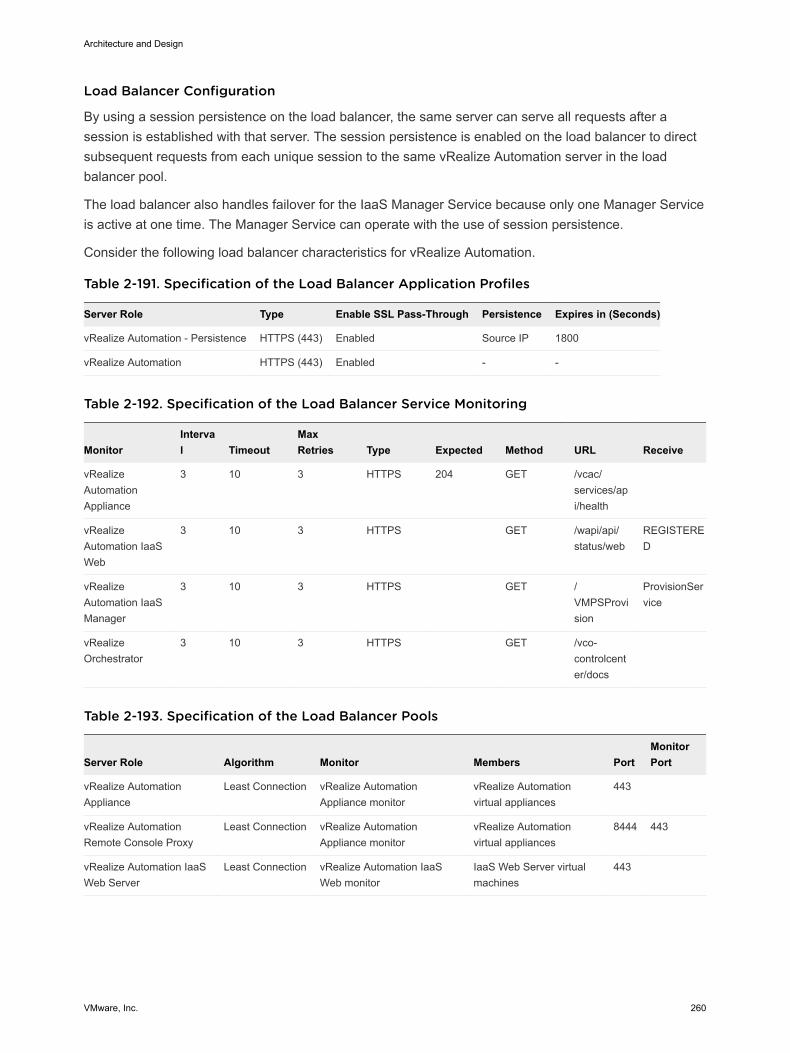
Load Balancer Configuration
By using a session persistence on the load balancer, the same server can serve all requests after asession is established with that server. The session persistence is enabled on the load balancer to directsubsequent requests from each unique session to the same vRealize Automation server in the loadbalancer pool.
The load balancer also handles failover for the IaaS Manager Service because only one Manager Serviceis active at one time. The Manager Service can operate with the use of session persistence.
Consider the following load balancer characteristics for vRealize Automation.
Table 2-191. Specification of the Load Balancer Application Profiles
Server Role Type Enable SSL Pass-Through Persistence Expires in (Seconds)
vRealize Automation - Persistence HTTPS (443) Enabled Source IP 1800
vRealize Automation HTTPS (443) Enabled - -
Table 2-192. Specification of the Load Balancer Service Monitoring
MonitorInterval Timeout
MaxRetries Type Expected Method URL Receive
vRealizeAutomationAppliance
3 10 3 HTTPS 204 GET /vcac/services/api/health
vRealizeAutomation IaaSWeb
3 10 3 HTTPS GET /wapi/api/status/web
REGISTERED
vRealizeAutomation IaaSManager
3 10 3 HTTPS GET /VMPSProvision
ProvisionService
vRealizeOrchestrator
3 10 3 HTTPS GET /vco-controlcenter/docs
Table 2-193. Specification of the Load Balancer Pools
Server Role Algorithm Monitor Members PortMonitorPort
vRealize AutomationAppliance
Least Connection vRealize AutomationAppliance monitor
vRealize Automationvirtual appliances
443
vRealize AutomationRemote Console Proxy
Least Connection vRealize AutomationAppliance monitor
vRealize Automationvirtual appliances
8444 443
vRealize Automation IaaSWeb Server
Least Connection vRealize Automation IaaSWeb monitor
IaaS Web Server virtualmachines
443
Architecture and Design
VMware, Inc. 260
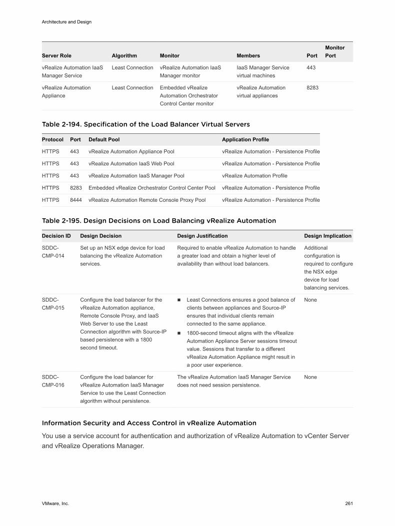
Server Role Algorithm Monitor Members PortMonitorPort
vRealize Automation IaaSManager Service
Least Connection vRealize Automation IaaSManager monitor
IaaS Manager Servicevirtual machines
443
vRealize AutomationAppliance
Least Connection Embedded vRealizeAutomation OrchestratorControl Center monitor
vRealize Automationvirtual appliances
8283
Table 2-194. Specification of the Load Balancer Virtual Servers
Protocol Port Default Pool Application Profile
HTTPS 443 vRealize Automation Appliance Pool vRealize Automation - Persistence Profile
HTTPS 443 vRealize Automation IaaS Web Pool vRealize Automation - Persistence Profile
HTTPS 443 vRealize Automation IaaS Manager Pool vRealize Automation Profile
HTTPS 8283 Embedded vRealize Orchestrator Control Center Pool vRealize Automation - Persistence Profile
HTTPS 8444 vRealize Automation Remote Console Proxy Pool vRealize Automation - Persistence Profile
Table 2-195. Design Decisions on Load Balancing vRealize Automation
Decision ID Design Decision Design Justification Design Implication
SDDC-CMP-014
Set up an NSX edge device for loadbalancing the vRealize Automationservices.
Required to enable vRealize Automation to handlea greater load and obtain a higher level ofavailability than without load balancers.
Additionalconfiguration isrequired to configurethe NSX edgedevice for loadbalancing services.
SDDC-CMP-015
Configure the load balancer for thevRealize Automation appliance,Remote Console Proxy, and IaaSWeb Server to use the LeastConnection algorithm with Source-IPbased persistence with a 1800second timeout.
n Least Connections ensures a good balance ofclients between appliances and Source-IPensures that individual clients remainconnected to the same appliance.
n 1800-second timeout aligns with the vRealizeAutomation Appliance Server sessions timeoutvalue. Sessions that transfer to a differentvRealize Automation Appliance might result ina poor user experience.
None
SDDC-CMP-016
Configure the load balancer forvRealize Automation IaaS ManagerService to use the Least Connectionalgorithm without persistence.
The vRealize Automation IaaS Manager Servicedoes not need session persistence.
None
Information Security and Access Control in vRealize Automation
You use a service account for authentication and authorization of vRealize Automation to vCenter Serverand vRealize Operations Manager.
Architecture and Design
VMware, Inc. 261
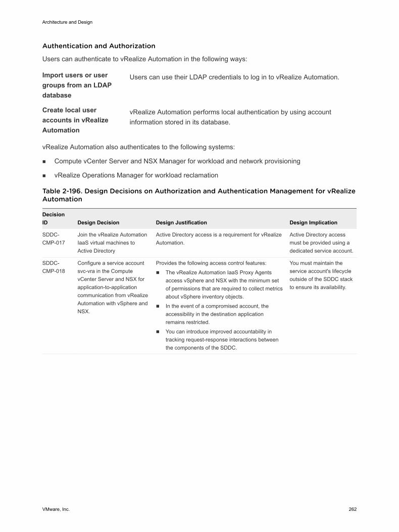
Authentication and Authorization
Users can authenticate to vRealize Automation in the following ways:
Import users or usergroups from an LDAPdatabase
Users can use their LDAP credentials to log in to vRealize Automation.
Create local useraccounts in vRealizeAutomation
vRealize Automation performs local authentication by using accountinformation stored in its database.
vRealize Automation also authenticates to the following systems:
n Compute vCenter Server and NSX Manager for workload and network provisioning
n vRealize Operations Manager for workload reclamation
Table 2-196. Design Decisions on Authorization and Authentication Management for vRealizeAutomation
DecisionID Design Decision Design Justification Design Implication
SDDC-CMP-017
Join the vRealize AutomationIaaS virtual machines toActive Directory
Active Directory access is a requirement for vRealizeAutomation.
Active Directory accessmust be provided using adedicated service account.
SDDC-CMP-018
Configure a service accountsvc-vra in the ComputevCenter Server and NSX forapplication-to-applicationcommunication from vRealizeAutomation with vSphere andNSX.
Provides the following access control features:
n The vRealize Automation IaaS Proxy Agentsaccess vSphere and NSX with the minimum setof permissions that are required to collect metricsabout vSphere inventory objects.
n In the event of a compromised account, theaccessibility in the destination applicationremains restricted.
n You can introduce improved accountability intracking request-response interactions betweenthe components of the SDDC.
You must maintain theservice account's lifecycleoutside of the SDDC stackto ensure its availability.
Architecture and Design
VMware, Inc. 262
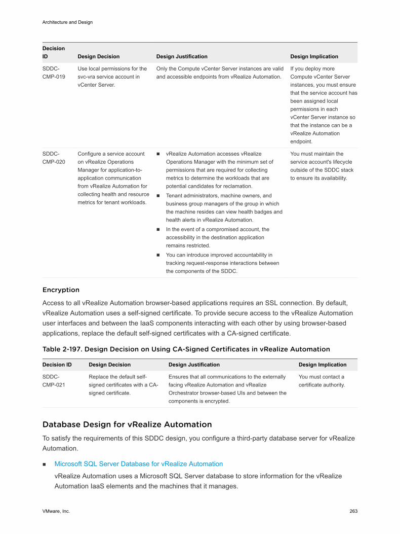
DecisionID Design Decision Design Justification Design Implication
SDDC-CMP-019
Use local permissions for thesvc-vra service account invCenter Server.
Only the Compute vCenter Server instances are validand accessible endpoints from vRealize Automation.
If you deploy moreCompute vCenter Serverinstances, you must ensurethat the service account hasbeen assigned localpermissions in eachvCenter Server instance sothat the instance can be avRealize Automationendpoint.
SDDC-CMP-020
Configure a service accounton vRealize OperationsManager for application-to-application communicationfrom vRealize Automation forcollecting health and resourcemetrics for tenant workloads.
n vRealize Automation accesses vRealizeOperations Manager with the minimum set ofpermissions that are required for collectingmetrics to determine the workloads that arepotential candidates for reclamation.
n Tenant administrators, machine owners, andbusiness group managers of the group in whichthe machine resides can view health badges andhealth alerts in vRealize Automation.
n In the event of a compromised account, theaccessibility in the destination applicationremains restricted.
n You can introduce improved accountability intracking request-response interactions betweenthe components of the SDDC.
You must maintain theservice account's lifecycleoutside of the SDDC stackto ensure its availability.
Encryption
Access to all vRealize Automation browser-based applications requires an SSL connection. By default,vRealize Automation uses a self-signed certificate. To provide secure access to the vRealize Automationuser interfaces and between the IaaS components interacting with each other by using browser-basedapplications, replace the default self-signed certificates with a CA-signed certificate.
Table 2-197. Design Decision on Using CA-Signed Certificates in vRealize Automation
Decision ID Design Decision Design Justification Design Implication
SDDC-CMP-021
Replace the default self-signed certificates with a CA-signed certificate.
Ensures that all communications to the externallyfacing vRealize Automation and vRealizeOrchestrator browser-based UIs and between thecomponents is encrypted.
You must contact acertificate authority.
Database Design for vRealize Automation To satisfy the requirements of this SDDC design, you configure a third-party database server for vRealizeAutomation.
n Microsoft SQL Server Database for vRealize Automation
vRealize Automation uses a Microsoft SQL Server database to store information for the vRealizeAutomation IaaS elements and the machines that it manages.
Architecture and Design
VMware, Inc. 263
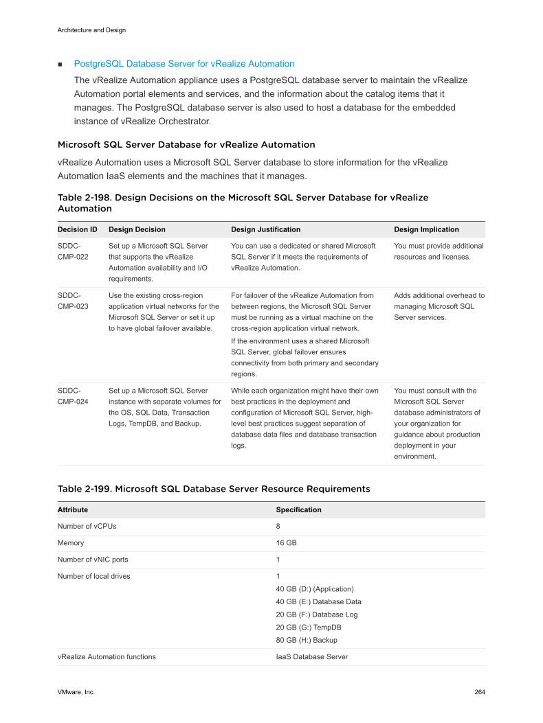
n PostgreSQL Database Server for vRealize Automation
The vRealize Automation appliance uses a PostgreSQL database server to maintain the vRealizeAutomation portal elements and services, and the information about the catalog items that itmanages. The PostgreSQL database server is also used to host a database for the embeddedinstance of vRealize Orchestrator.
Microsoft SQL Server Database for vRealize Automation
vRealize Automation uses a Microsoft SQL Server database to store information for the vRealizeAutomation IaaS elements and the machines that it manages.
Table 2-198. Design Decisions on the Microsoft SQL Server Database for vRealizeAutomation
Decision ID Design Decision Design Justification Design Implication
SDDC-CMP-022
Set up a Microsoft SQL Serverthat supports the vRealizeAutomation availability and I/Orequirements.
You can use a dedicated or shared MicrosoftSQL Server if it meets the requirements ofvRealize Automation.
You must provide additionalresources and licenses.
SDDC-CMP-023
Use the existing cross-regionapplication virtual networks for theMicrosoft SQL Server or set it upto have global failover available.
For failover of the vRealize Automation frombetween regions, the Microsoft SQL Servermust be running as a virtual machine on thecross-region application virtual network.
If the environment uses a shared MicrosoftSQL Server, global failover ensuresconnectivity from both primary and secondaryregions.
Adds additional overhead tomanaging Microsoft SQLServer services.
SDDC-CMP-024
Set up а Microsoft SQL Serverinstance with separate volumes forthe OS, SQL Data, TransactionLogs, TempDB, and Backup.
While each organization might have their ownbest practices in the deployment andconfiguration of Microsoft SQL Server, high-level best practices suggest separation ofdatabase data files and database transactionlogs.
You must consult with theMicrosoft SQL Serverdatabase administrators ofyour organization forguidance about productiondeployment in yourenvironment.
Table 2-199. Microsoft SQL Database Server Resource Requirements
Attribute Specification
Number of vCPUs 8
Memory 16 GB
Number of vNIC ports 1
Number of local drives 1
40 GB (D:) (Application)
40 GB (E:) Database Data
20 GB (F:) Database Log
20 GB (G:) TempDB
80 GB (H:) Backup
vRealize Automation functions IaaS Database Server
Architecture and Design
VMware, Inc. 264
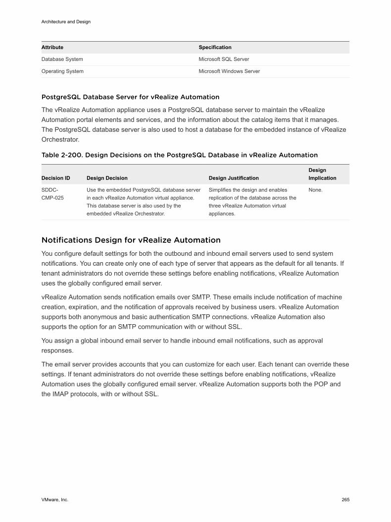
Attribute Specification
Database System Microsoft SQL Server
Operating System Microsoft Windows Server
PostgreSQL Database Server for vRealize Automation
The vRealize Automation appliance uses a PostgreSQL database server to maintain the vRealizeAutomation portal elements and services, and the information about the catalog items that it manages.The PostgreSQL database server is also used to host a database for the embedded instance of vRealizeOrchestrator.
Table 2-200. Design Decisions on the PostgreSQL Database in vRealize Automation
Decision ID Design Decision Design JustificationDesignImplication
SDDC-CMP-025
Use the embedded PostgreSQL database serverin each vRealize Automation virtual appliance.This database server is also used by theembedded vRealize Orchestrator.
Simplifies the design and enablesreplication of the database across thethree vRealize Automation virtualappliances.
None.
Notifications Design for vRealize Automation You configure default settings for both the outbound and inbound email servers used to send systemnotifications. You can create only one of each type of server that appears as the default for all tenants. Iftenant administrators do not override these settings before enabling notifications, vRealize Automationuses the globally configured email server.
vRealize Automation sends notification emails over SMTP. These emails include notification of machinecreation, expiration, and the notification of approvals received by business users. vRealize Automationsupports both anonymous and basic authentication SMTP connections. vRealize Automation alsosupports the option for an SMTP communication with or without SSL.
You assign a global inbound email server to handle inbound email notifications, such as approvalresponses.
The email server provides accounts that you can customize for each user. Each tenant can override thesesettings. If tenant administrators do not override these settings before enabling notifications, vRealizeAutomation uses the globally configured email server. vRealize Automation supports both the POP andthe IMAP protocols, with or without SSL.
Architecture and Design
VMware, Inc. 265
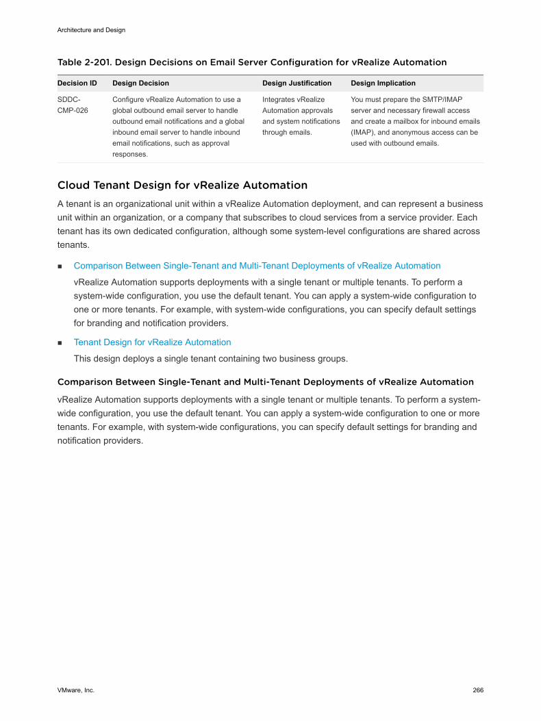
Table 2-201. Design Decisions on Email Server Configuration for vRealize Automation
Decision ID Design Decision Design Justification Design Implication
SDDC-CMP-026
Configure vRealize Automation to use aglobal outbound email server to handleoutbound email notifications and a globalinbound email server to handle inboundemail notifications, such as approvalresponses.
Integrates vRealizeAutomation approvalsand system notificationsthrough emails.
You must prepare the SMTP/IMAPserver and necessary firewall accessand create a mailbox for inbound emails(IMAP), and anonymous access can beused with outbound emails.
Cloud Tenant Design for vRealize Automation A tenant is an organizational unit within a vRealize Automation deployment, and can represent a businessunit within an organization, or a company that subscribes to cloud services from a service provider. Eachtenant has its own dedicated configuration, although some system-level configurations are shared acrosstenants.
n Comparison Between Single-Tenant and Multi-Tenant Deployments of vRealize Automation
vRealize Automation supports deployments with a single tenant or multiple tenants. To perform asystem-wide configuration, you use the default tenant. You can apply a system-wide configuration toone or more tenants. For example, with system-wide configurations, you can specify default settingsfor branding and notification providers.
n Tenant Design for vRealize Automation
This design deploys a single tenant containing two business groups.
Comparison Between Single-Tenant and Multi-Tenant Deployments of vRealize Automation
vRealize Automation supports deployments with a single tenant or multiple tenants. To perform a system-wide configuration, you use the default tenant. You can apply a system-wide configuration to one or moretenants. For example, with system-wide configurations, you can specify default settings for branding andnotification providers.
Architecture and Design
VMware, Inc. 266
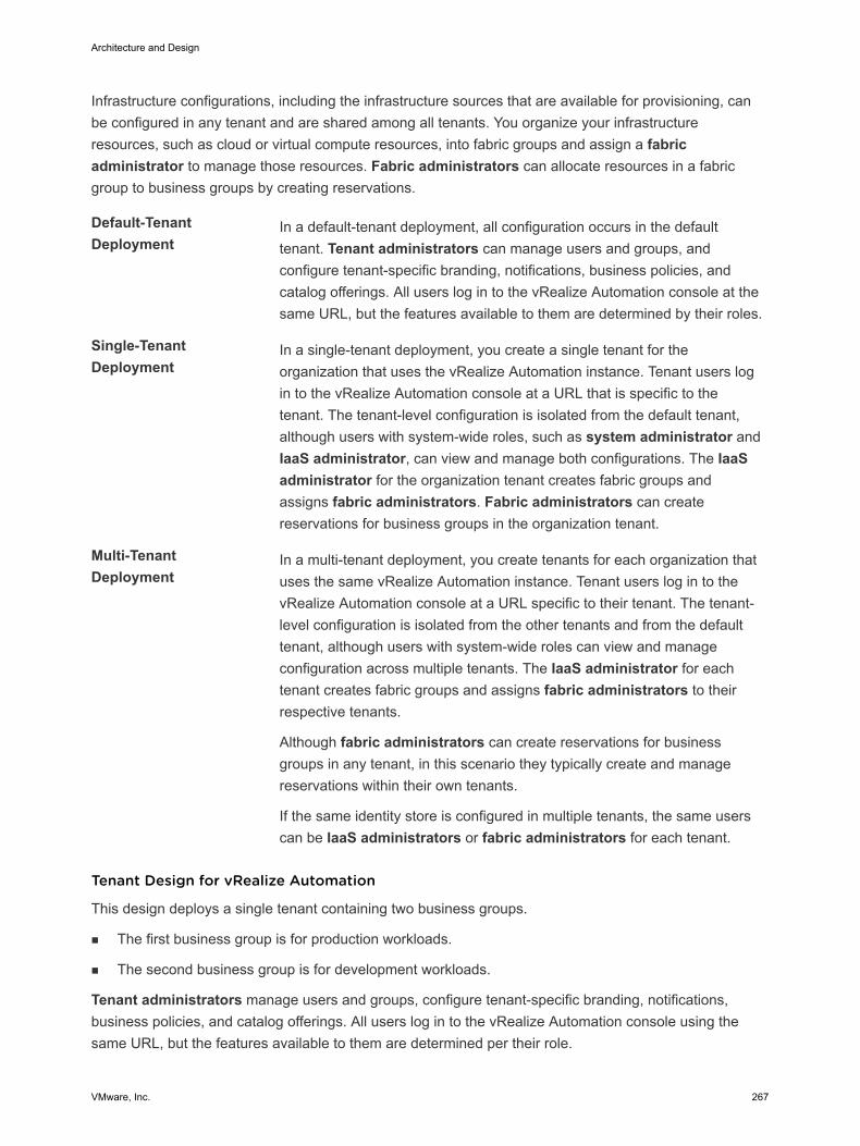
Infrastructure configurations, including the infrastructure sources that are available for provisioning, canbe configured in any tenant and are shared among all tenants. You organize your infrastructureresources, such as cloud or virtual compute resources, into fabric groups and assign a fabricadministrator to manage those resources. Fabric administrators can allocate resources in a fabricgroup to business groups by creating reservations.
Default-TenantDeployment
In a default-tenant deployment, all configuration occurs in the defaulttenant. Tenant administrators can manage users and groups, andconfigure tenant-specific branding, notifications, business policies, andcatalog offerings. All users log in to the vRealize Automation console at thesame URL, but the features available to them are determined by their roles.
Single-TenantDeployment
In a single-tenant deployment, you create a single tenant for theorganization that uses the vRealize Automation instance. Tenant users login to the vRealize Automation console at a URL that is specific to thetenant. The tenant-level configuration is isolated from the default tenant,although users with system-wide roles, such as system administrator andIaaS administrator, can view and manage both configurations. The IaaSadministrator for the organization tenant creates fabric groups andassigns fabric administrators. Fabric administrators can createreservations for business groups in the organization tenant.
Multi-TenantDeployment
In a multi-tenant deployment, you create tenants for each organization thatuses the same vRealize Automation instance. Tenant users log in to thevRealize Automation console at a URL specific to their tenant. The tenant-level configuration is isolated from the other tenants and from the defaulttenant, although users with system-wide roles can view and manageconfiguration across multiple tenants. The IaaS administrator for eachtenant creates fabric groups and assigns fabric administrators to theirrespective tenants.
Although fabric administrators can create reservations for businessgroups in any tenant, in this scenario they typically create and managereservations within their own tenants.
If the same identity store is configured in multiple tenants, the same userscan be IaaS administrators or fabric administrators for each tenant.
Tenant Design for vRealize Automation
This design deploys a single tenant containing two business groups.
n The first business group is for production workloads.
n The second business group is for development workloads.
Tenant administrators manage users and groups, configure tenant-specific branding, notifications,business policies, and catalog offerings. All users log in to the vRealize Automation console using thesame URL, but the features available to them are determined per their role.
Architecture and Design
VMware, Inc. 267
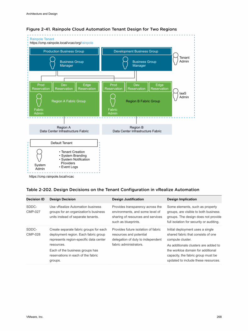
Figure 2-41. Rainpole Cloud Automation Tenant Design for Two Regions
Production Business Group
Business Group Manager
Development Business Group
TenantAdminBusiness Group
Manager
FabricAdmin
IaaSAdmin
ProdReservation
DevReservation
EdgeReservation
Region A Fabric Group
ProdReservation
DevReservation
EdgeReservation
Region B Fabric Group
Region A Data Center Infrastructure Fabric
Region B Data Center Infrastructure Fabric
https://cmp.rainpole.local/vcac
• Tenant Creation• System Branding• System Notification Providers• Event LogsSystem
Admin
Default Tenant
FabricAdmin
Rainpole Tenanthttps://cmp.rainpole.local/vcac/org/rainpole
Table 2-202. Design Decisions on the Tenant Configuration in vRealize Automation
Decision ID Design Decision Design Justification Design Implication
SDDC-CMP-027
Use vRealize Automation businessgroups for an organization's businessunits instead of separate tenants.
Provides transparency across theenvironments, and some level ofsharing of resources and servicessuch as blueprints.
Some elements, such as propertygroups, are visible to both businessgroups. The design does not providefull isolation for security or auditing.
SDDC-CMP-028
Create separate fabric groups for eachdeployment region. Each fabric grouprepresents region-specific data centerresources.
Each of the business groups hasreservations in each of the fabricgroups.
Provides future isolation of fabricresources and potentialdelegation of duty to independentfabric administrators.
Initial deployment uses a singleshared fabric that consists of onecompute cluster.
As additionals clusters are added tothe workloa domain for additionalcapacity, the fabric group must beupdated to include these resources.
Architecture and Design
VMware, Inc. 268
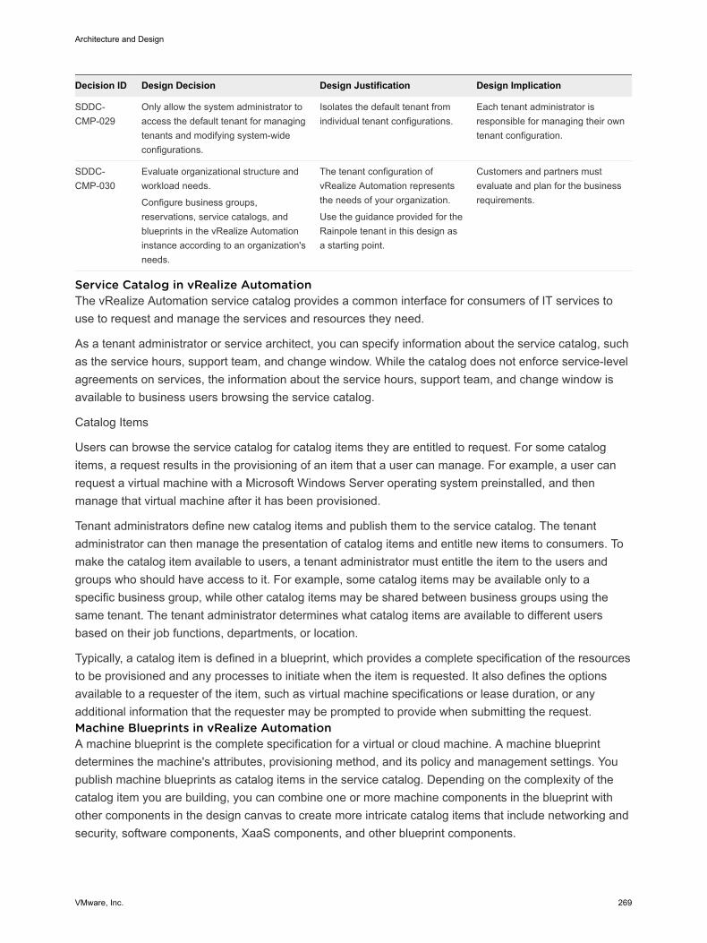
Decision ID Design Decision Design Justification Design Implication
SDDC-CMP-029
Only allow the system administrator toaccess the default tenant for managingtenants and modifying system-wideconfigurations.
Isolates the default tenant fromindividual tenant configurations.
Each tenant administrator isresponsible for managing their owntenant configuration.
SDDC-CMP-030
Evaluate organizational structure andworkload needs.
Configure business groups,reservations, service catalogs, andblueprints in the vRealize Automationinstance according to an organization'sneeds.
The tenant configuration ofvRealize Automation representsthe needs of your organization.
Use the guidance provided for theRainpole tenant in this design asa starting point.
Customers and partners mustevaluate and plan for the businessrequirements.
Service Catalog in vRealize Automation The vRealize Automation service catalog provides a common interface for consumers of IT services touse to request and manage the services and resources they need.
As a tenant administrator or service architect, you can specify information about the service catalog, suchas the service hours, support team, and change window. While the catalog does not enforce service-levelagreements on services, the information about the service hours, support team, and change window isavailable to business users browsing the service catalog.
Catalog Items
Users can browse the service catalog for catalog items they are entitled to request. For some catalogitems, a request results in the provisioning of an item that a user can manage. For example, a user canrequest a virtual machine with a Microsoft Windows Server operating system preinstalled, and thenmanage that virtual machine after it has been provisioned.
Tenant administrators define new catalog items and publish them to the service catalog. The tenantadministrator can then manage the presentation of catalog items and entitle new items to consumers. Tomake the catalog item available to users, a tenant administrator must entitle the item to the users andgroups who should have access to it. For example, some catalog items may be available only to aspecific business group, while other catalog items may be shared between business groups using thesame tenant. The tenant administrator determines what catalog items are available to different usersbased on their job functions, departments, or location.
Typically, a catalog item is defined in a blueprint, which provides a complete specification of the resourcesto be provisioned and any processes to initiate when the item is requested. It also defines the optionsavailable to a requester of the item, such as virtual machine specifications or lease duration, or anyadditional information that the requester may be prompted to provide when submitting the request.Machine Blueprints in vRealize Automation A machine blueprint is the complete specification for a virtual or cloud machine. A machine blueprintdetermines the machine's attributes, provisioning method, and its policy and management settings. Youpublish machine blueprints as catalog items in the service catalog. Depending on the complexity of thecatalog item you are building, you can combine one or more machine components in the blueprint withother components in the design canvas to create more intricate catalog items that include networking andsecurity, software components, XaaS components, and other blueprint components.
Architecture and Design
VMware, Inc. 269
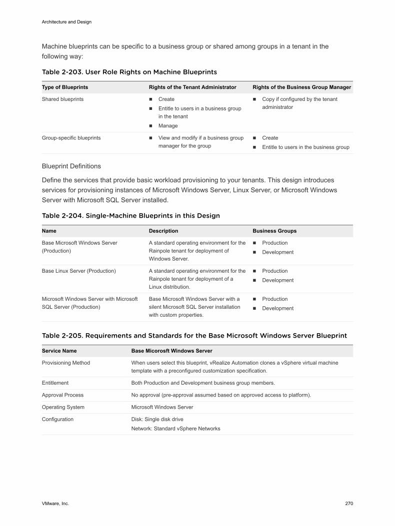
Machine blueprints can be specific to a business group or shared among groups in a tenant in thefollowing way:
Table 2-203. User Role Rights on Machine Blueprints
Type of Blueprints Rights of the Tenant Administrator Rights of the Business Group Manager
Shared blueprints n Create
n Entitle to users in a business groupin the tenant
n Manage
n Copy if configured by the tenantadministrator
Group-specific blueprints n View and modify if a business groupmanager for the group
n Create
n Entitle to users in the business group
Blueprint Definitions
Define the services that provide basic workload provisioning to your tenants. This design introducesservices for provisioning instances of Microsoft Windows Server, Linux Server, or Microsoft WindowsServer with Microsoft SQL Server installed.
Table 2-204. Single-Machine Blueprints in this Design
Name Description Business Groups
Base Microsoft Windows Server(Production)
A standard operating environment for theRainpole tenant for deployment ofWindows Server.
n Production
n Development
Base Linux Server (Production) A standard operating environment for theRainpole tenant for deployment of aLinux distribution.
n Production
n Development
Microsoft Windows Server with MicrosoftSQL Server (Production)
Base Microsoft Windows Server with asilent Microsoft SQL Server installationwith custom properties.
n Production
n Development
Table 2-205. Requirements and Standards for the Base Microsoft Windows Server Blueprint
Service Name Base Micorosft Windows Server
Provisioning Method When users select this blueprint, vRealize Automation clones a vSphere virtual machinetemplate with a preconfigured customization specification.
Entitlement Both Production and Development business group members.
Approval Process No approval (pre-approval assumed based on approved access to platform).
Operating System Microsoft Windows Server
Configuration Disk: Single disk drive
Network: Standard vSphere Networks
Architecture and Design
VMware, Inc. 270
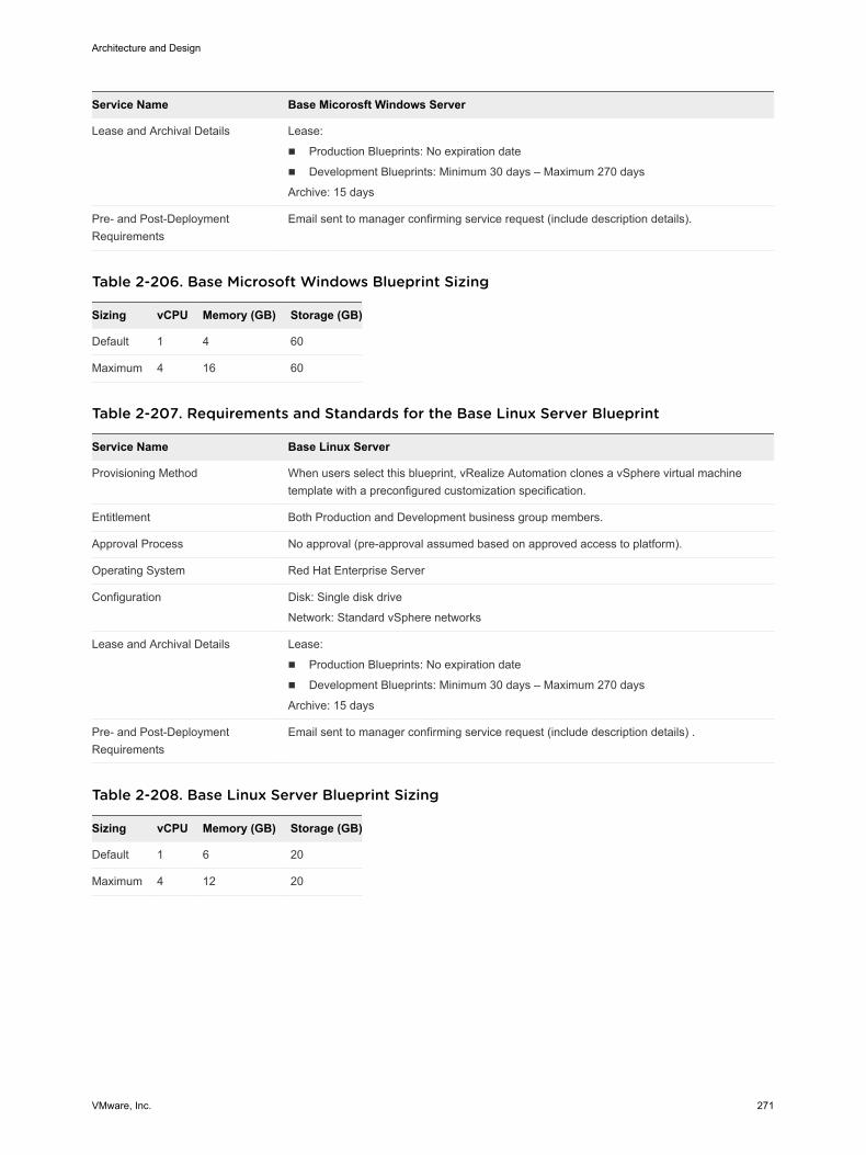
Service Name Base Micorosft Windows Server
Lease and Archival Details Lease:
n Production Blueprints: No expiration date
n Development Blueprints: Minimum 30 days – Maximum 270 days
Archive: 15 days
Pre- and Post-DeploymentRequirements
Email sent to manager confirming service request (include description details).
Table 2-206. Base Microsoft Windows Blueprint Sizing
Sizing vCPU Memory (GB) Storage (GB)
Default 1 4 60
Maximum 4 16 60
Table 2-207. Requirements and Standards for the Base Linux Server Blueprint
Service Name Base Linux Server
Provisioning Method When users select this blueprint, vRealize Automation clones a vSphere virtual machinetemplate with a preconfigured customization specification.
Entitlement Both Production and Development business group members.
Approval Process No approval (pre-approval assumed based on approved access to platform).
Operating System Red Hat Enterprise Server
Configuration Disk: Single disk drive
Network: Standard vSphere networks
Lease and Archival Details Lease:
n Production Blueprints: No expiration date
n Development Blueprints: Minimum 30 days – Maximum 270 days
Archive: 15 days
Pre- and Post-DeploymentRequirements
Email sent to manager confirming service request (include description details) .
Table 2-208. Base Linux Server Blueprint Sizing
Sizing vCPU Memory (GB) Storage (GB)
Default 1 6 20
Maximum 4 12 20
Architecture and Design
VMware, Inc. 271
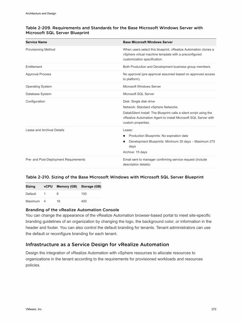
Table 2-209. Requirements and Standards for the Base Microsoft Windows Server withMicrosoft SQL Server Blueprint
Service Name Base Micorosft Windows Server
Provisioning Method When users select this blueprint, vRealize Automation clones avSphere virtual machine template with a preconfiguredcustomization specification.
Entitlement Both Production and Development business group members.
Approval Process No approval (pre-approval assumed based on approved accessto platform).
Operating System Microsoft Windows Server
Database System Microsoft SQL Server
Configuration Disk: Single disk drive
Network: Standard vSphere Networks
DatabSilent Install: The Blueprint calls a silent script using thevRealize Automation Agent to install Microsoft SQL Server withcustom properties.
Lease and Archival Details Lease:
n Production Blueprints: No expiration date
n Development Blueprints: Minimum 30 days – Maximum 270days
Archive: 15 days
Pre- and Post-Deployment Requirements Email sent to manager confirming service request (includedescription details)
Table 2-210. Sizing of the Base Microsoft Windows with Microsoft SQL Server Blueprint
Sizing vCPU Memory (GB) Storage (GB)
Default 1 8 100
Maximum 4 16 400
Branding of the vRealize Automation Console You can change the appearance of the vRealize Automation browser-based portal to meet site-specificbranding guidelines of an organization by changing the logo, the background color, or information in theheader and footer. You can also control the default branding for tenants. Tenant administrators can usethe default or reconfigure branding for each tenant.
Infrastructure as a Service Design for vRealize Automation Design the integration of vRealize Automation with vSphere resources to allocate resources toorganizations in the tenant according to the requirements for provisioned workloads and resourcespolicies.
Architecture and Design
VMware, Inc. 272
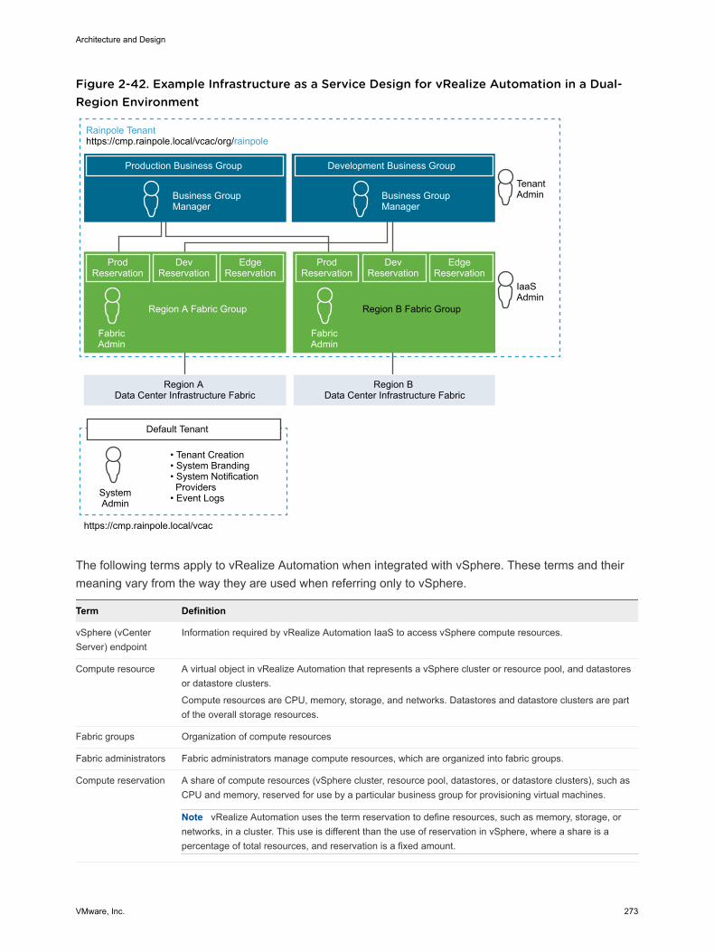
Figure 2-42. Example Infrastructure as a Service Design for vRealize Automation in a Dual-Region Environment
Production Business Group
Business Group Manager
Development Business Group
TenantAdminBusiness Group
Manager
FabricAdmin
IaaSAdmin
ProdReservation
DevReservation
EdgeReservation
Region A Fabric Group
ProdReservation
DevReservation
EdgeReservation
Region B Fabric Group
Region A Data Center Infrastructure Fabric
Region B Data Center Infrastructure Fabric
https://cmp.rainpole.local/vcac
• Tenant Creation• System Branding• System Notification Providers• Event LogsSystem
Admin
Default Tenant
FabricAdmin
Rainpole Tenanthttps://cmp.rainpole.local/vcac/org/rainpole
The following terms apply to vRealize Automation when integrated with vSphere. These terms and theirmeaning vary from the way they are used when referring only to vSphere.
Term Definition
vSphere (vCenterServer) endpoint
Information required by vRealize Automation IaaS to access vSphere compute resources.
Compute resource A virtual object in vRealize Automation that represents a vSphere cluster or resource pool, and datastoresor datastore clusters.
Compute resources are CPU, memory, storage, and networks. Datastores and datastore clusters are partof the overall storage resources.
Fabric groups Organization of compute resources
Fabric administrators Fabric administrators manage compute resources, which are organized into fabric groups.
Compute reservation A share of compute resources (vSphere cluster, resource pool, datastores, or datastore clusters), such asCPU and memory, reserved for use by a particular business group for provisioning virtual machines.
Note vRealize Automation uses the term reservation to define resources, such as memory, storage, ornetworks, in a cluster. This use is different than the use of reservation in vSphere, where a share is apercentage of total resources, and reservation is a fixed amount.
Architecture and Design
VMware, Inc. 273
Term Definition
Storage reservation Similar to compute reservation, but pertaining only to a share of the available storage resources. In thiscontext, you specify a storage reservation from a datastore in GB.
Business groups A collection of consumers, usually corresponding to an organization's business units or departments. Onlyusers in the business group can request resources.
Reservation policy A logical label or a pointer to the original reservation.
vRealize Automation IaaS determines the reservation from which a particular virtual machine isprovisioned. Each virtual reservation can be added to one reservation policy.
Blueprint The complete specification for a virtual machine, determining the machine attributes, the manner in which itis provisioned, and its policy and management settings.
The users of a business group use blueprints to create virtual machines on a virtual reservation (computeresource) based on the reservation policy, and using platform and cloning types. It also lets you specify oradd machine resources and build profiles.
Architecture and Design
VMware, Inc. 274
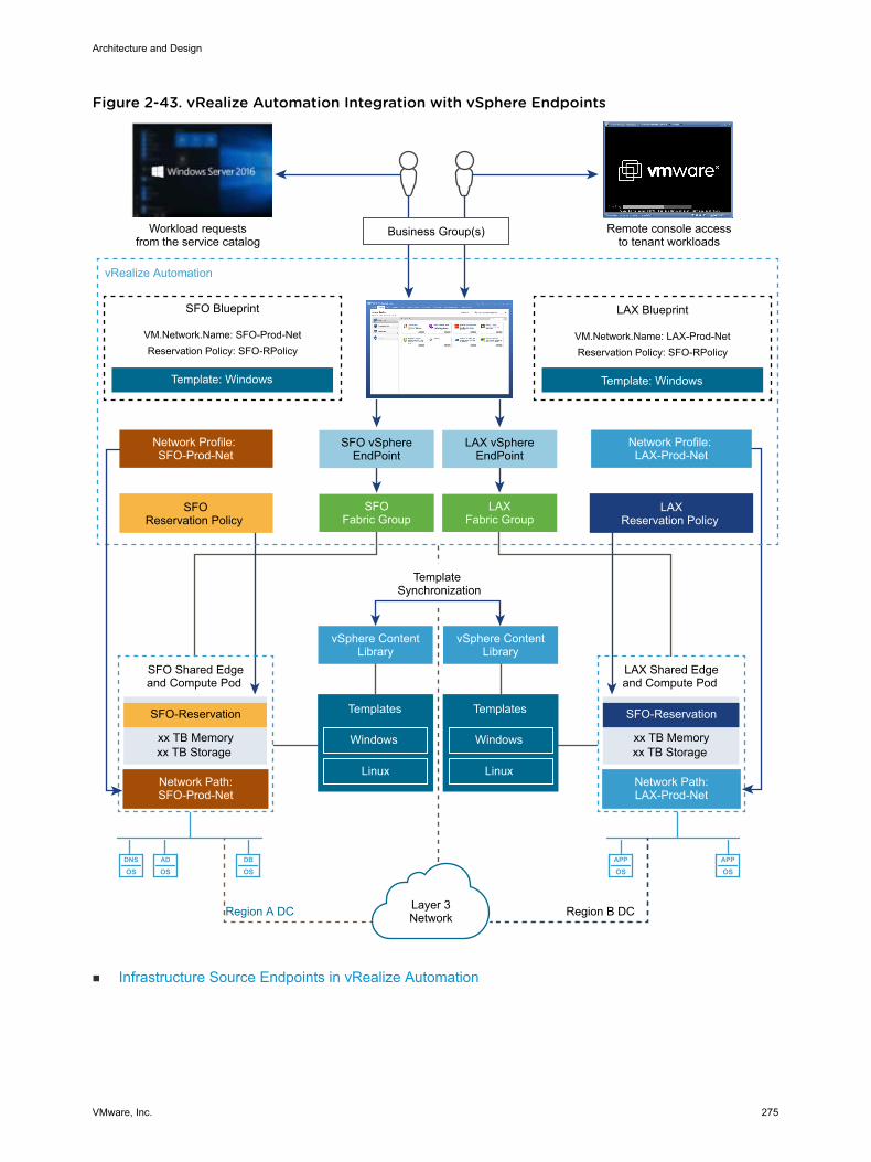
Figure 2-43. vRealize Automation Integration with vSphere Endpoints
DNS
OSAD
OSDB
OSAPP
OSAPP
OS
Business Group(s)Workload requestsfrom the service catalog
Remote console accessto tenant workloads
SFO vSphereEndPoint
LAX vSphereEndPoint
SFОFabric Group
LAXFabric Group
SFO Blueprint
VM.Network.Name: SFO-Prod-NetReservation Policy: SFO-RPolicy
Template: Windows
LAX Blueprint
VM.Network.Name: LAX-Prod-NetReservation Policy: SFO-RPolicy
Template: Windows
Network Profile: SFO-Prod-Net
Network Profile: LAX-Prod-Net
SFОReservation Policy
LAXReservation Policy
vRealize Automation
vSphere ContentLibrary
Templates
Windows
Linux
Template Synchronization
vSphere ContentLibrary
Templates
Windows
Linux Network Path:SFO-Prod-Net
SFO-Reservation
SFO Shared Edgeand Compute Pod
xx TB Memoryxx TB Storage
Network Path:LAX-Prod-Net
SFO-Reservation
LAX Shared Edgeand Compute Pod
xx TB Memoryxx TB Storage
Layer 3NetworkRegion A DC Region B DC
n Infrastructure Source Endpoints in vRealize Automation
Architecture and Design
VMware, Inc. 275
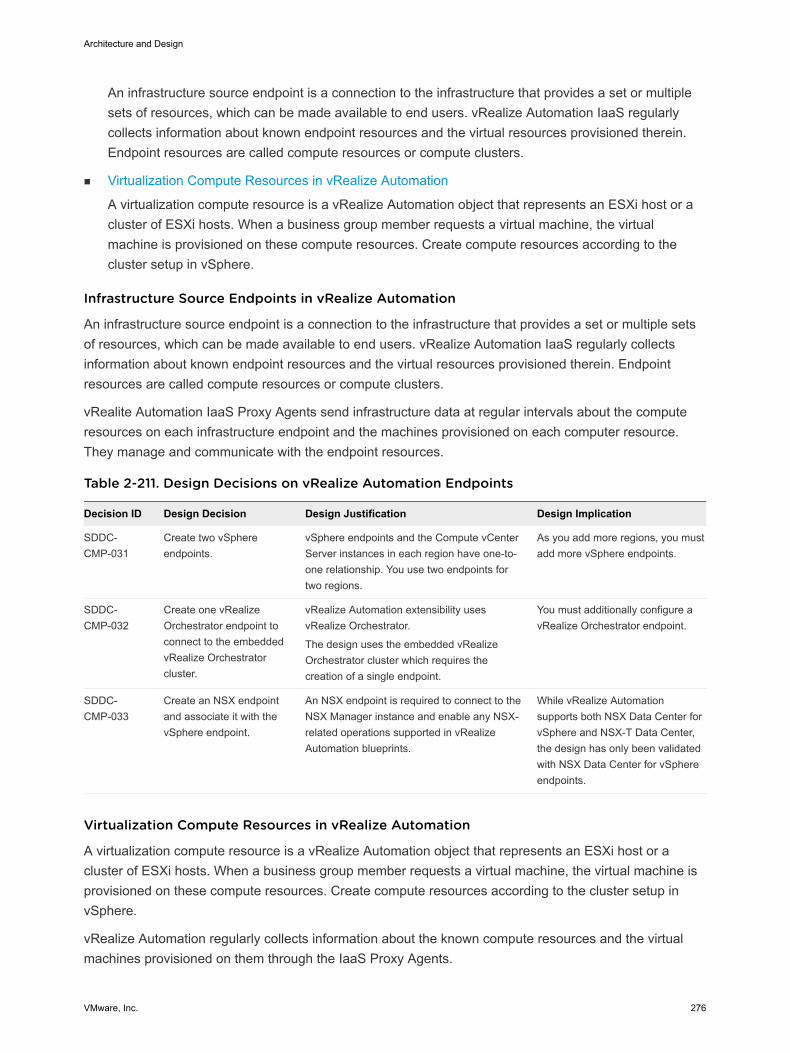
An infrastructure source endpoint is a connection to the infrastructure that provides a set or multiplesets of resources, which can be made available to end users. vRealize Automation IaaS regularlycollects information about known endpoint resources and the virtual resources provisioned therein.Endpoint resources are called compute resources or compute clusters.
n Virtualization Compute Resources in vRealize Automation
A virtualization compute resource is a vRealize Automation object that represents an ESXi host or acluster of ESXi hosts. When a business group member requests a virtual machine, the virtualmachine is provisioned on these compute resources. Create compute resources according to thecluster setup in vSphere.
Infrastructure Source Endpoints in vRealize Automation
An infrastructure source endpoint is a connection to the infrastructure that provides a set or multiple setsof resources, which can be made available to end users. vRealize Automation IaaS regularly collectsinformation about known endpoint resources and the virtual resources provisioned therein. Endpointresources are called compute resources or compute clusters.
vRealite Automation IaaS Proxy Agents send infrastructure data at regular intervals about the computeresources on each infrastructure endpoint and the machines provisioned on each computer resource.They manage and communicate with the endpoint resources.
Table 2-211. Design Decisions on vRealize Automation Endpoints
Decision ID Design Decision Design Justification Design Implication
SDDC-CMP-031
Create two vSphereendpoints.
vSphere endpoints and the Compute vCenterServer instances in each region have one-to-one relationship. You use two endpoints fortwo regions.
As you add more regions, you mustadd more vSphere endpoints.
SDDC-CMP-032
Create one vRealizeOrchestrator endpoint toconnect to the embeddedvRealize Orchestratorcluster.
vRealize Automation extensibility usesvRealize Orchestrator.
The design uses the embedded vRealizeOrchestrator cluster which requires thecreation of a single endpoint.
You must additionally configure avRealize Orchestrator endpoint.
SDDC-CMP-033
Create an NSX endpointand associate it with thevSphere endpoint.
An NSX endpoint is required to connect to theNSX Manager instance and enable any NSX-related operations supported in vRealizeAutomation blueprints.
While vRealize Automationsupports both NSX Data Center forvSphere and NSX-T Data Center,the design has only been validatedwith NSX Data Center for vSphereendpoints.
Virtualization Compute Resources in vRealize Automation
A virtualization compute resource is a vRealize Automation object that represents an ESXi host or acluster of ESXi hosts. When a business group member requests a virtual machine, the virtual machine isprovisioned on these compute resources. Create compute resources according to the cluster setup invSphere.
vRealize Automation regularly collects information about the known compute resources and the virtualmachines provisioned on them through the IaaS Proxy Agents.
Architecture and Design
VMware, Inc. 276
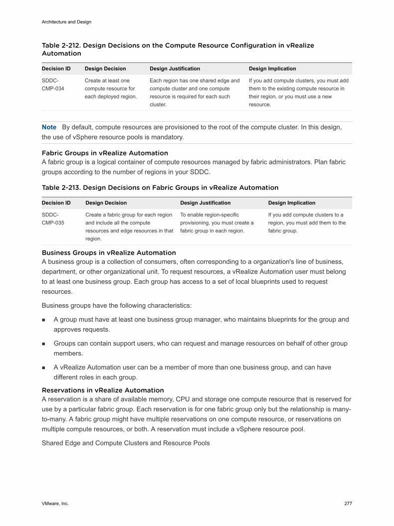
Table 2-212. Design Decisions on the Compute Resource Configuration in vRealizeAutomation
Decision ID Design Decision Design Justification Design Implication
SDDC-CMP-034
Create at least onecompute resource foreach deployed region.
Each region has one shared edge andcompute cluster and one computeresource is required for each suchcluster.
If you add compute clusters, you must addthem to the existing compute resource intheir region, or you must use a newresource.
Note By default, compute resources are provisioned to the root of the compute cluster. In this design,the use of vSphere resource pools is mandatory.
Fabric Groups in vRealize Automation A fabric group is a logical container of compute resources managed by fabric administrators. Plan fabricgroups according to the number of regions in your SDDC.
Table 2-213. Design Decisions on Fabric Groups in vRealize Automation
Decision ID Design Decision Design Justification Design Implication
SDDC-CMP-035
Create a fabric group for each regionand include all the computeresources and edge resources in thatregion.
To enable region-specificprovisioning, you must create afabric group in each region.
If you add compute clusters to aregion, you must add them to thefabric group.
Business Groups in vRealize Automation A business group is a collection of consumers, often corresponding to a organization's line of business,department, or other organizational unit. To request resources, a vRealize Automation user must belongto at least one business group. Each group has access to a set of local blueprints used to requestresources.
Business groups have the following characteristics:
n A group must have at least one business group manager, who maintains blueprints for the group andapproves requests.
n Groups can contain support users, who can request and manage resources on behalf of other groupmembers.
n A vRealize Automation user can be a member of more than one business group, and can havedifferent roles in each group.
Reservations in vRealize Automation A reservation is a share of available memory, CPU and storage one compute resource that is reserved foruse by a particular fabric group. Each reservation is for one fabric group only but the relationship is many-to-many. A fabric group might have multiple reservations on one compute resource, or reservations onmultiple compute resources, or both. A reservation must include a vSphere resource pool.
Shared Edge and Compute Clusters and Resource Pools
Architecture and Design
VMware, Inc. 277
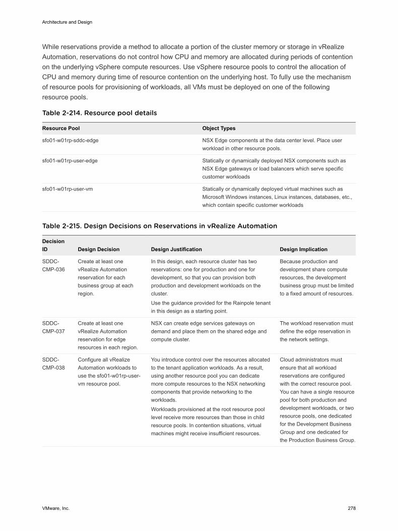
While reservations provide a method to allocate a portion of the cluster memory or storage in vRealizeAutomation, reservations do not control how CPU and memory are allocated during periods of contentionon the underlying vSphere compute resources. Use vSphere resource pools to control the allocation ofCPU and memory during time of resource contention on the underlying host. To fully use the mechanismof resource pools for provisioning of workloads, all VMs must be deployed on one of the followingresource pools.
Table 2-214. Resource pool details
Resource Pool Object Types
sfo01-w01rp-sddc-edge NSX Edge components at the data center level. Place userworkload in other resource pools.
sfo01-w01rp-user-edge Statically or dynamically deployed NSX components such asNSX Edge gateways or load balancers which serve specificcustomer workloads
sfo01-w01rp-user-vm Statically or dynamically deployed virtual machines such asMicrosoft Windows instances, Linux instances, databases, etc.,which contain specific customer workloads
Table 2-215. Design Decisions on Reservations in vRealize Automation
DecisionID Design Decision Design Justification Design Implication
SDDC-CMP-036
Create at least onevRealize Automationreservation for eachbusiness group at eachregion.
In this design, each resource cluster has tworeservations: one for production and one fordevelopment, so that you can provision bothproduction and development workloads on thecluster.
Use the guidance provided for the Rainpole tenantin this design as a starting point.
Because production anddevelopment share computeresources, the developmentbusiness group must be limitedto a fixed amount of resources.
SDDC-CMP-037
Create at least onevRealize Automationreservation for edgeresources in each region.
NSX can create edge services gateways ondemand and place them on the shared edge andcompute cluster.
The workload reservation mustdefine the edge reservation inthe network settings.
SDDC-CMP-038
Configure all vRealizeAutomation workloads touse the sfo01-w01rp-user-vm resource pool.
You introduce control over the resources allocatedto the tenant application workloads. As a result,using another resource pool you can dedicatemore compute resources to the NSX networkingcomponents that provide networking to theworkloads.
Workloads provisioned at the root resource poollevel receive more resources than those in childresource pools. In contention situations, virtualmachines might receive insufficient resources.
Cloud administrators mustensure that all workloadreservations are configuredwith the correct resource pool.You can have a single resourcepool for both production anddevelopment workloads, or tworesource pools, one dedicatedfor the Development BusinessGroup and one dedicated forthe Production Business Group.
Architecture and Design
VMware, Inc. 278
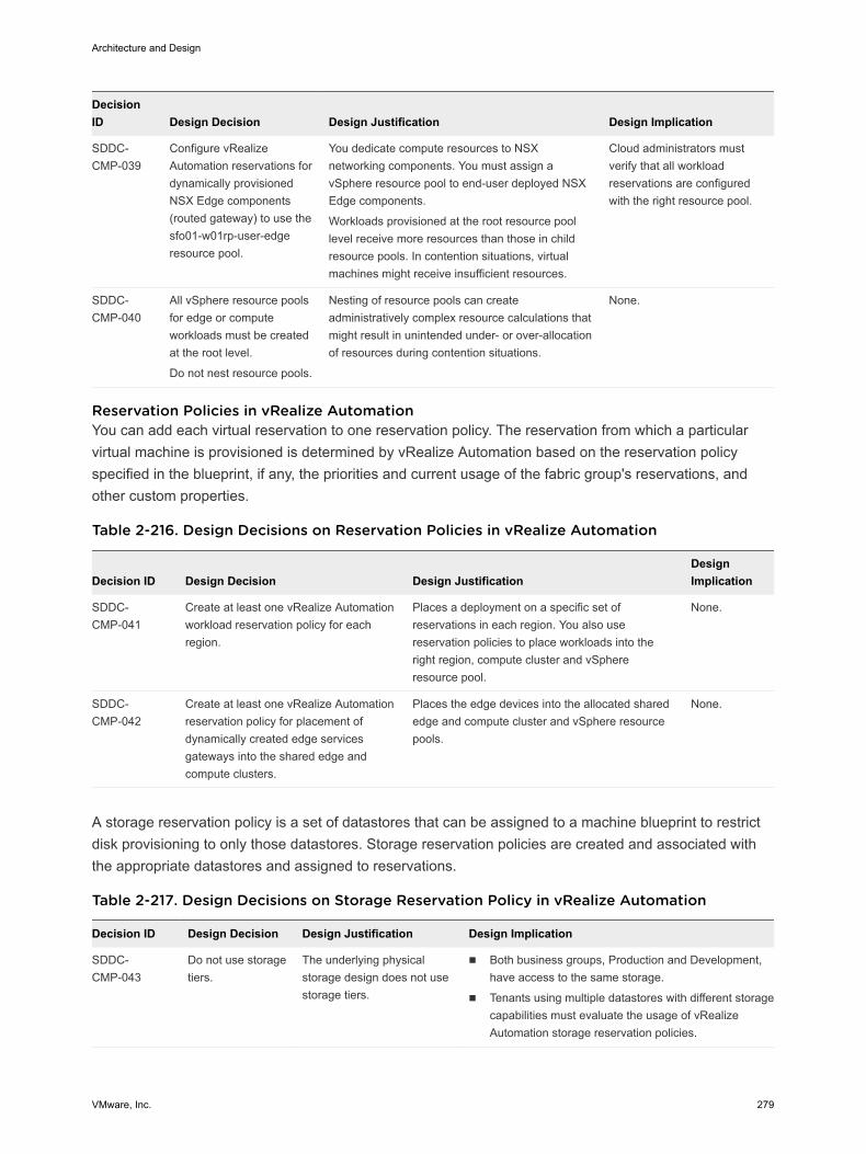
DecisionID Design Decision Design Justification Design Implication
SDDC-CMP-039
Configure vRealizeAutomation reservations fordynamically provisionedNSX Edge components(routed gateway) to use thesfo01-w01rp-user-edgeresource pool.
You dedicate compute resources to NSXnetworking components. You must assign avSphere resource pool to end-user deployed NSXEdge components.
Workloads provisioned at the root resource poollevel receive more resources than those in childresource pools. In contention situations, virtualmachines might receive insufficient resources.
Cloud administrators mustverify that all workloadreservations are configuredwith the right resource pool.
SDDC-CMP-040
All vSphere resource poolsfor edge or computeworkloads must be createdat the root level.
Do not nest resource pools.
Nesting of resource pools can createadministratively complex resource calculations thatmight result in unintended under- or over-allocationof resources during contention situations.
None.
Reservation Policies in vRealize Automation You can add each virtual reservation to one reservation policy. The reservation from which a particularvirtual machine is provisioned is determined by vRealize Automation based on the reservation policyspecified in the blueprint, if any, the priorities and current usage of the fabric group's reservations, andother custom properties.
Table 2-216. Design Decisions on Reservation Policies in vRealize Automation
Decision ID Design Decision Design JustificationDesignImplication
SDDC-CMP-041
Create at least one vRealize Automationworkload reservation policy for eachregion.
Places a deployment on a specific set ofreservations in each region. You also usereservation policies to place workloads into theright region, compute cluster and vSphereresource pool.
None.
SDDC-CMP-042
Create at least one vRealize Automationreservation policy for placement ofdynamically created edge servicesgateways into the shared edge andcompute clusters.
Places the edge devices into the allocated sharededge and compute cluster and vSphere resourcepools.
None.
A storage reservation policy is a set of datastores that can be assigned to a machine blueprint to restrictdisk provisioning to only those datastores. Storage reservation policies are created and associated withthe appropriate datastores and assigned to reservations.
Table 2-217. Design Decisions on Storage Reservation Policy in vRealize Automation
Decision ID Design Decision Design Justification Design Implication
SDDC-CMP-043
Do not use storagetiers.
The underlying physicalstorage design does not usestorage tiers.
n Both business groups, Production and Development,have access to the same storage.
n Tenants using multiple datastores with different storagecapabilities must evaluate the usage of vRealizeAutomation storage reservation policies.
Architecture and Design
VMware, Inc. 279
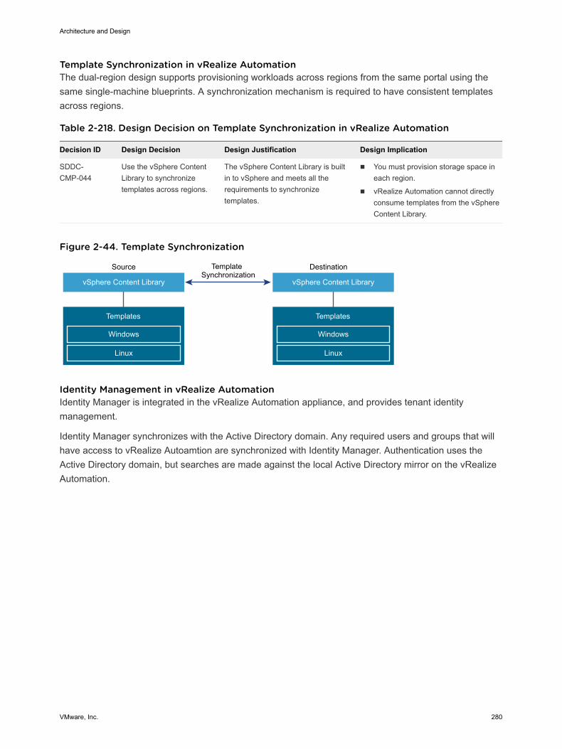
Template Synchronization in vRealize Automation The dual-region design supports provisioning workloads across regions from the same portal using thesame single-machine blueprints. A synchronization mechanism is required to have consistent templatesacross regions.
Table 2-218. Design Decision on Template Synchronization in vRealize Automation
Decision ID Design Decision Design Justification Design Implication
SDDC-CMP-044
Use the vSphere ContentLibrary to synchronizetemplates across regions.
The vSphere Content Library is builtin to vSphere and meets all therequirements to synchronizetemplates.
n You must provision storage space ineach region.
n vRealize Automation cannot directlyconsume templates from the vSphereContent Library.
Figure 2-44. Template Synchronization
vSphere Content Library
Source
Templates
Windows
Linux
DestinationTemplate Synchronization
vSphere Content Library
Templates
Windows
Linux
Identity Management in vRealize AutomationIdentity Manager is integrated in the vRealize Automation appliance, and provides tenant identitymanagement.
Identity Manager synchronizes with the Active Directory domain. Any required users and groups that willhave access to vRealize Autoamtion are synchronized with Identity Manager. Authentication uses theActive Directory domain, but searches are made against the local Active Directory mirror on the vRealizeAutomation.
Architecture and Design
VMware, Inc. 280
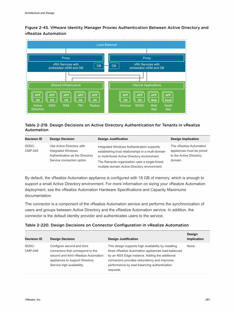
Figure 2-45. VMware Identity Manager Proxies Authentication Between Active Directory andvRealize Automation
APP
OS
APP
OS
APP
Web
APP
SaaS
APP
OS
APP
OS
APP
OS
APP
OS
APP
OS
Proxy
Internal Applications
vRA Services withembedded vIDM and DB
Horizon RDSH WebApp
SaaSApp
Load Balancer
Proxy
Shared Infrastructure
vRA Services withembedded vIDM and DB
Active Directory
DNS RSA PKI Radius
DB DB
Table 2-219. Design Decisions on Active Directory Authentication for Tenants in vRealizeAutomation
Decision ID Design Decision Design Justification Design Implication
SDDC-CMP-045
Use Active Directory withIntegrated WindowsAuthentication as the DirectoryService connection option.
Integrated Windows Authentication supportsestablishing trust relationships in a multi-domainor multi-forest Active Directory environment.
The Rainpole organization uses a single-forest,multiple-domain Active Directory environment.
The vRealize Automationappliances must be joinedto the Active Directorydomain.
By default, the vRealize Automation appliance is configured with 18 GB of memory, which is enough tosupport a small Active Directory environment. For more information on sizing your vRealize Automationdeployment, see the vRealize Automation Hardware Specifications and Capacity Maximumsdocumentation.
The connector is a component of the vRealize Automation service and performs the synchronization ofusers and groups between Active Directory and the vRealize Automation service. In addition, theconnector is the default identity provider and authenticates users to the service.
Table 2-220. Design Decisions on Connector Configuration in vRealize Automation
Decision ID Design Decision Design JustificationDesignImplication
SDDC-CMP-046
Configure second and thirdconnectors that correspond to thesecond and third vRealize Automationappliances to support DirectoryService high availability,
This design supports high availability by installingthree vRealize Automation appliances load-balancedby an NSX Edge instance. Adding the additionalconnectors provides redundancy and improvesperformance by load balancing authenticationrequests.
None.
Architecture and Design
VMware, Inc. 281
vRealize Business Design vRealize Business provides end-user transparency in the costs that are associated with operatingworkloads. vRealize Business shows provisioning costs both during a workload request and on a periodicbasis, regardless of whether the costs are charged-back to a specific business unit, or are showed-backto illustrate the value that the SDDC provides.
vRealize Business integrates with vRealize Automation to display costing during workload requests andon an ongoing basis with cost reporting by user, business group, or tenant. Also, tenant administratorscan create a wide range of custom reports according to the requirements of their organizations. SeeLogical Design of vRealize Automation and Physical Design of vRealize Automation .
Table 2-221. Resource Requirements for vRealize Business for Cloud per Virtual Machine
Attribute Specification
Number of vCPUs 4
Memory n 8 GB for a server
n 2 GB for a data collector
vRealize Business function Server or data collector
Table 2-222. Design Decision on vRealize Business
Decision ID Design Decision Design Justification Design Implication
SDDC-CMP-VRBC-001 Deploy vRealize Business forCloud and integrate it withvRealize Automation.
You introduce tenant andworkload costings.
You must deploy moreappliances for the vRealizeBusiness for Cloud serverinstance and data collectorinstances.
SDDC-CMP-VRBC-002 Use the default vRealizeBusiness for Cloud virtualappliance size of 8 GB RAM.
For the vRealize Business forCloud data collectorsinstances, use a reducedmemory size of 2 GB RAM.
The default virtual appliancesize of vRealize Business forCloud supports the designobjective of 10,000 virtualmachines
vRealize Business for Clouddata collectors do not runserver service, and can runon 2 GB RAM.
None.
SDDC-CMP-vRBC-003 Use the default vRealizeBusiness for Cloud referencecosting database.
The default reference costingis based on industryinformation and is periodicallyupdated.
Default reference costing mightnot accurately represent actualcustomer costs.
The vRealize Business forCloud server requires Internetaccess to periodically updatethe reference database.
Architecture and Design
VMware, Inc. 282
Decision ID Design Decision Design Justification Design Implication
SDDC-CMP-VRBC-004 Deploy vRealize Business forCloud as a three-VMarchitecture with server inRegion A and remote datacollectors in Region A andRegion B.
For best performance, thevRealize Business for Clouddata collectors must be localto the resource which theyare configured to collect datafrom.
The data collectors reside inRegion A and Region B.
If the environment does nothave disaster recovery support,you must deploy an additionalappliance for the remote datacollector, although the vRealizeBusiness for Cloud server canhandle the load on its own.
SDDC-CMP-VRBC-005 Deploy the vRealize Businessfor Cloud server in the cross-region logical network.
The vRealize Business forCllud deployment depends onvRealize Automation. Duringa disaster recovery event, thevRealize Business for Cloudserver instance migrates withvRealize Automation.
None.
SDDC-CMP-VRBC-006 Deploy a vRealize Businessfor Cloud data collector ineach region-specific logicalnetwork.
vRealize Business for Clouddata collectors are a region-specific installation.
During a disaster recoveryevent, the vRealize Businessfor Cloud data collector doesnot need to migrate withvRealize Automation.
The communication withvCenter Server involves anextra Layer 3 hop through anNSX Edge device.
SDDC-CMP-VRBC-007 Replace the default self-signed certificates with a CA-signed certificate.
Ensures that allcommunications to theexternally facing vRealizeBusiness for Cloud browser-based UIs and services aswell as between thevRealizeAutomation components isencrypted.
You must contact a certificateauthority.
vRealize Orchestrator Design VMware vRealize Orchestrator is a development and process automation platform that provides a libraryof extensible workflows. With the vRealize Orchestrator workflows, you can create and run automatedconfigurable processes to manage the VMware vSphere infrastructure and other VMware and third-partytechnologies.
In this design, vRealize Automation uses the vRealize Orchestrator plug-in to connect to vCenter Serverfor customized virtual machine provisioning and post-provisioning actions.
n Physical Design of vRealize Orchestrator
This design uses the vRealize Orchestrator instance that is embedded in the vRealize Automationappliance, instead of using an external vRealize Orchestrator instance. Using the embeddedvRealize Orchestrator instance simplifies the deployment model and improves the operationalefficiency.
Architecture and Design
VMware, Inc. 283
n Configuration of vRealize Orchestrator
The vRealize Orchestrator configuration includes guidance on client configuration, databaseconfiguration, SSL certificates, and plug-ins.
n Scalability of vRealize Orchestrator
vRealize Orchestrator supports both scale-up and scale-out scalability.
Physical Design of vRealize Orchestrator This design uses the vRealize Orchestrator instance that is embedded in the vRealize Automationappliance, instead of using an external vRealize Orchestrator instance. Using the embedded vRealizeOrchestrator instance simplifies the deployment model and improves the operational efficiency.
Table 2-223. Design Decisions on vRealize Orchestrator
Decision ID Design Decision Design JustificationDesignImplication
SDDC-CMP-VRO-001
Use the vRealizeOrchestrator instances thatare embedded in thedeployed vRealizeAutomation appliances.
The embedded vRealizeOrchestrator instances willoperate in cluster mode.
The use of embedded vRealize Orchestrator instances has thefollowing advantages:
n Provides faster time to value.
n Reduces the number of appliances to manage.
n Provides easier upgrade path and better support-ability.
n Improves performance.
n Removes the need for an external database.
n Overall simplification of the design leading to a reduced numberof virtual appliances and enhanced support-ability.
Note Using the embedded instance of vRealize Orchestrator isapplicable in most use cases. However, refer to the productdocumentation to be aware of the cases where using the externalvRealize Orchestrator is applicable.
None.
n Authentication to vRealize Orchestrator
An embedded vRealize Orchestrator instance supports only the vRealize Automation authenticationmethod.
n Server Mode of vRealize Orchestrator
vRealize Orchestrator supports both standalone mode and cluster mode. In this design, vRealizeOrchestrator is configured in cluster mode, because the deployment contains three vRealizeAutomation appliances, each running an embedded vRealize Orchestrator instance.
n Load Balancer Configuration for vRealize Orchestrator
To provision network access to the vRealize Orchestrator Control Center, you configure loadbalancing for the vRealize Orchestrator instances that are embedded in the vRealize Automationappliances.
Architecture and Design
VMware, Inc. 284
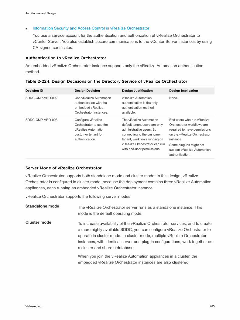
n Information Security and Access Control in vRealize Orchestrator
You use a service account for the authentication and authorization of vRealize Orchestrator tovCenter Server. You also establish secure communications to the vCenter Server instances by usingCA-signed certificates.
Authentication to vRealize Orchestrator
An embedded vRealize Orchestrator instance supports only the vRealize Automation authenticationmethod.
Table 2-224. Design Decisions on the Directory Service of vRealize Orchestrator
Decision ID Design Decision Design Justification Design Implication
SDDC-CMP-VRO-002 Use vRealize Automationauthentication with theembedded vRealizeOrchestrator instances.
vRealize Automationauthentication is the onlyauthentication methodavailable.
None.
SDDC-CMP-VRO-003 Configure vRealizeOrchestrator to use thevRealize Automationcustomer tenant forauthentication.
The vRealize Automationdefault tenant users are onlyadministrative users. Byconnecting to the customertenant, workflows running onvRealize Orchestrator can runwith end-user permissions.
End users who run vRealizeOrchestrator workflows arerequired to have permissionson the vRealize Orchestratorinstance.
Some plug-ins might notsupport vRealize Automationauthentication.
Server Mode of vRealize Orchestrator
vRealize Orchestrator supports both standalone mode and cluster mode. In this design, vRealizeOrchestrator is configured in cluster mode, because the deployment contains three vRealize Automationappliances, each running an embedded vRealize Orchestrator instance.
vRealize Orchestrator supports the following server modes.
Standalone mode The vRealize Orchestrator server runs as a standalone instance. Thismode is the default operating mode.
Cluster mode To increase availability of the vRealize Orchestrator services, and to createa more highly available SDDC, you can configure vRealize Orchestrator tooperate in cluster mode. In cluster mode, multiple vRealize Orchestratorinstances, with identical server and plug-in configurations, work together asa cluster and share a database.
When you join the vRealize Automation appliances in a cluster, theembedded vRealize Orchestrator instances are also clustered.
Architecture and Design
VMware, Inc. 285
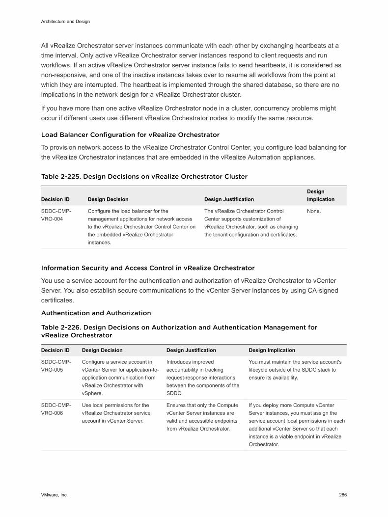
All vRealize Orchestrator server instances communicate with each other by exchanging heartbeats at atime interval. Only active vRealize Orchestrator server instances respond to client requests and runworkflows. If an active vRealize Orchestrator server instance fails to send heartbeats, it is considered asnon-responsive, and one of the inactive instances takes over to resume all workflows from the point atwhich they are interrupted. The heartbeat is implemented through the shared database, so there are noimplications in the network design for a vRealize Orchestrator cluster.
If you have more than one active vRealize Orchestrator node in a cluster, concurrency problems mightoccur if different users use different vRealize Orchestrator nodes to modify the same resource.
Load Balancer Configuration for vRealize Orchestrator
To provision network access to the vRealize Orchestrator Control Center, you configure load balancing forthe vRealize Orchestrator instances that are embedded in the vRealize Automation appliances.
Table 2-225. Design Decisions on vRealize Orchestrator Cluster
Decision ID Design Decision Design JustificationDesignImplication
SDDC-CMP-VRO-004
Configure the load balancer for themanagement applications for network accessto the vRealize Orchestrator Control Center onthe embedded vRealize Orchestratorinstances.
The vRealize Orchestrator ControlCenter supports customization ofvRealize Orchestrator, such as changingthe tenant configuration and certificates.
None.
Information Security and Access Control in vRealize Orchestrator
You use a service account for the authentication and authorization of vRealize Orchestrator to vCenterServer. You also establish secure communications to the vCenter Server instances by using CA-signedcertificates.
Authentication and Authorization
Table 2-226. Design Decisions on Authorization and Authentication Management forvRealize Orchestrator
Decision ID Design Decision Design Justification Design Implication
SDDC-CMP-VRO-005
Configure a service account invCenter Server for application-to-application communication fromvRealize Orchestrator withvSphere.
Introduces improvedaccountability in trackingrequest-response interactionsbetween the components of theSDDC.
You must maintain the service account'slifecycle outside of the SDDC stack toensure its availability.
SDDC-CMP-VRO-006
Use local permissions for thevRealize Orchestrator serviceaccount in vCenter Server.
Ensures that only the ComputevCenter Server instances arevalid and accessible endpointsfrom vRealize Orchestrator.
If you deploy more Compute vCenterServer instances, you must assign theservice account local permissions in eachadditional vCenter Server so that eachinstance is a viable endpoint in vRealizeOrchestrator.
Architecture and Design
VMware, Inc. 286
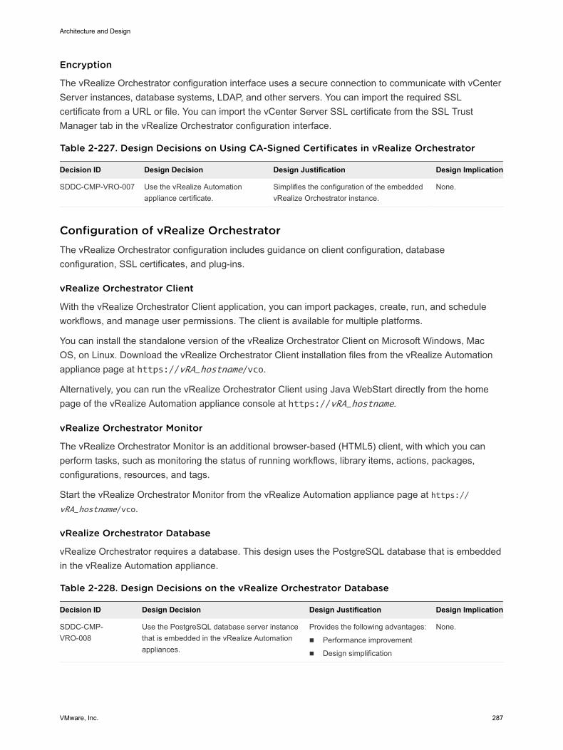
Encryption
The vRealize Orchestrator configuration interface uses a secure connection to communicate with vCenterServer instances, database systems, LDAP, and other servers. You can import the required SSLcertificate from a URL or file. You can import the vCenter Server SSL certificate from the SSL TrustManager tab in the vRealize Orchestrator configuration interface.
Table 2-227. Design Decisions on Using CA-Signed Certificates in vRealize Orchestrator
Decision ID Design Decision Design Justification Design Implication
SDDC-CMP-VRO-007 Use the vRealize Automationappliance certificate.
Simplifies the configuration of the embeddedvRealize Orchestrator instance.
None.
Configuration of vRealize Orchestrator The vRealize Orchestrator configuration includes guidance on client configuration, databaseconfiguration, SSL certificates, and plug-ins.
vRealize Orchestrator Client
With the vRealize Orchestrator Client application, you can import packages, create, run, and scheduleworkflows, and manage user permissions. The client is available for multiple platforms.
You can install the standalone version of the vRealize Orchestrator Client on Microsoft Windows, MacOS, on Linux. Download the vRealize Orchestrator Client installation files from the vRealize Automationappliance page at https://vRA_hostname/vco.
Alternatively, you can run the vRealize Orchestrator Client using Java WebStart directly from the homepage of the vRealize Automation appliance console at https://vRA_hostname.
vRealize Orchestrator Monitor
The vRealize Orchestrator Monitor is an additional browser-based (HTML5) client, with which you canperform tasks, such as monitoring the status of running workflows, library items, actions, packages,configurations, resources, and tags.
Start the vRealize Orchestrator Monitor from the vRealize Automation appliance page at https://vRA_hostname/vco.
vRealize Orchestrator Database
vRealize Orchestrator requires a database. This design uses the PostgreSQL database that is embeddedin the vRealize Automation appliance.
Table 2-228. Design Decisions on the vRealize Orchestrator Database
Decision ID Design Decision Design Justification Design Implication
SDDC-CMP-VRO-008
Use the PostgreSQL database server instancethat is embedded in the vRealize Automationappliances.
Provides the following advantages:
n Performance improvement
n Design simplification
None.
Architecture and Design
VMware, Inc. 287
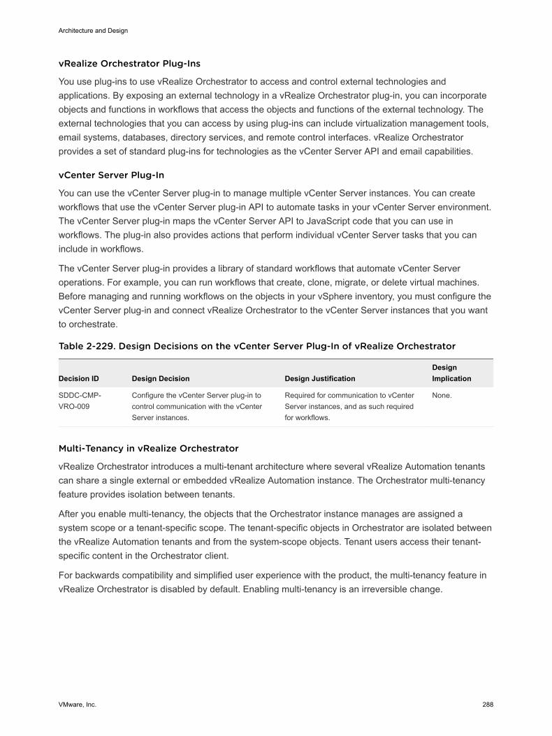
vRealize Orchestrator Plug-Ins
You use plug-ins to use vRealize Orchestrator to access and control external technologies andapplications. By exposing an external technology in a vRealize Orchestrator plug-in, you can incorporateobjects and functions in workflows that access the objects and functions of the external technology. Theexternal technologies that you can access by using plug-ins can include virtualization management tools,email systems, databases, directory services, and remote control interfaces. vRealize Orchestratorprovides a set of standard plug-ins for technologies as the vCenter Server API and email capabilities.
vCenter Server Plug-In
You can use the vCenter Server plug-in to manage multiple vCenter Server instances. You can createworkflows that use the vCenter Server plug-in API to automate tasks in your vCenter Server environment.The vCenter Server plug-in maps the vCenter Server API to JavaScript code that you can use inworkflows. The plug-in also provides actions that perform individual vCenter Server tasks that you caninclude in workflows.
The vCenter Server plug-in provides a library of standard workflows that automate vCenter Serveroperations. For example, you can run workflows that create, clone, migrate, or delete virtual machines.Before managing and running workflows on the objects in your vSphere inventory, you must configure thevCenter Server plug-in and connect vRealize Orchestrator to the vCenter Server instances that you wantto orchestrate.
Table 2-229. Design Decisions on the vCenter Server Plug-In of vRealize Orchestrator
Decision ID Design Decision Design JustificationDesignImplication
SDDC-CMP-VRO-009
Configure the vCenter Server plug-in tocontrol communication with the vCenterServer instances.
Required for communication to vCenterServer instances, and as such requiredfor workflows.
None.
Multi-Tenancy in vRealize Orchestrator
vRealize Orchestrator introduces a multi-tenant architecture where several vRealize Automation tenantscan share a single external or embedded vRealize Automation instance. The Orchestrator multi-tenancyfeature provides isolation between tenants.
After you enable multi-tenancy, the objects that the Orchestrator instance manages are assigned asystem scope or a tenant-specific scope. Тhe tenant-specific objects in Orchestrator are isolated betweenthe vRealize Automation tenants and from the system-scope objects. Tenant users access their tenant-specific content in the Orchestrator client.
For backwards compatibility and simplified user experience with the product, the multi-tenancy feature invRealize Orchestrator is disabled by default. Enabling multi-tenancy is an irreversible change.
Architecture and Design
VMware, Inc. 288
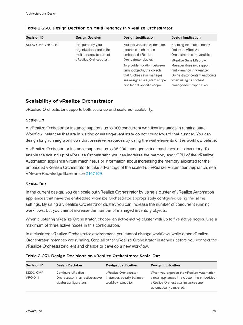
Table 2-230. Design Decision on Multi-Tenancy in vRealize Orchestrator
Decision ID Design Decision Design Justification Design Implication
SDDC-CMP-VRO-010 If required by yourorganization, enable themulti-tenancy feature ofvRealize Orchestrator .
Multiple vRealize Automationtenants can share theembedded vRealizeOrchestrator cluster.
To provide isolation betweentenant objects, the objectsthat Orchestrator managesare assigned a system scopeor a tenant-specific scope.
Enabling the multi-tenancyfeature of vRealizeOrchestrator is irreversible.
vRealize Suite LifecycleManager does not supportmulti-tenancy in vRealizeOrchestrator content endpointswhen using its contentmanagement capabilities.
Scalability of vRealize OrchestratorvRealize Orchestrator supports both scale-up and scale-out scalability.
Scale-Up
A vRealize Orchestrator instance supports up to 300 concurrent workflow instances in running state.Workflow instances that are in waiting or waiting-event state do not count toward that number. You candesign long running workflows that preserve resources by using the wait elements of the workflow palette.
A vRealize Orchestrator instance supports up to 35,000 managed virtual machines in its inventory. Toenable the scaling up of vRealize Orchestrator, you can increase the memory and vCPU of the vRealizeAutomation appliance virtual machines. For information about increasing the memory allocated for theembedded vRealize Orchestrator to take advantage of the scaled-up vRealize Automation appliance, seeVMware Knowledge Base article 2147109.
Scale-Out
In the current design, you can scale out vRealize Orchestrator by using a cluster of vRealize Automationappliances that have the embedded vRealize Orchestrator appropriately configured using the samesettings. By using a vRealize Orchestrator cluster, you can increase the number of concurrent runningworkflows, but you cannot increase the number of managed inventory objects.
When clustering vRealize Orchestrator, choose an active-active cluster with up to five active nodes. Use amaximum of three active nodes in this configuration.
In a clustered vRealize Orchestrator environment, you cannot change workflows while other vRealizeOrchestrator instances are running. Stop all other vRealize Orchestrator instances before you connect thevRealize Orchestrator client and change or develop a new workflow.
Table 2-231. Design Decisions on vRealize Orchestrator Scale-Out
Decision ID Design Decision Design Justification Design Implication
SDDC-CMP-VRO-011
Configure vRealizeOrchestrator in an active-activecluster configuration.
vRealize Orchestratorinstances equally balanceworkflow execution.
When you organize the vRealize Automationvirtual appliances in a cluster, the embeddedvRealize Orchestrator instances areautomatically clustered.
Architecture and Design
VMware, Inc. 289
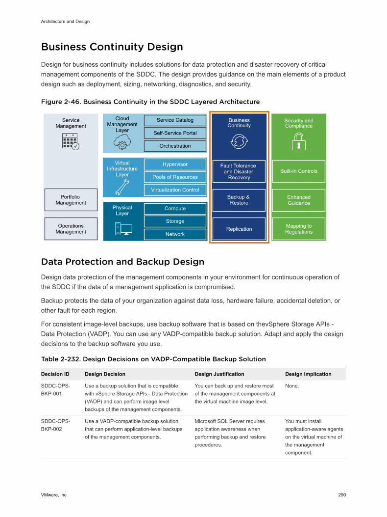
Business Continuity Design Design for business continuity includes solutions for data protection and disaster recovery of criticalmanagement components of the SDDC. The design provides guidance on the main elements of a productdesign such as deployment, sizing, networking, diagnostics, and security.
Figure 2-46. Business Continuity in the SDDC Layered Architecture
ServiceManagement
Portfolio Management
OperationsManagement
CloudManagement
Layer
Service Catalog
Self-Service Portal
Orchestration
BusinessContinuity
Fault Tolerance and Disaster
Recovery
Backup & Restore
Hypervisor
Pools of Resources
Virtualization Control
VirtualInfrastructure
Layer
Compute
Storage
Network
PhysicalLayer
Replication
Security and Compliance
Mapping to Regulations
Enhanced Guidance
Built-In Controls
Data Protection and Backup Design Design data protection of the management components in your environment for continuous operation ofthe SDDC if the data of a management application is compromised.
Backup protects the data of your organization against data loss, hardware failure, accidental deletion, orother fault for each region.
For consistent image-level backups, use backup software that is based on thevSphere Storage APIs -Data Protection (VADP). You can use any VADP-compatible backup solution. Adapt and apply the designdecisions to the backup software you use.
Table 2-232. Design Decisions on VADP-Compatible Backup Solution
Decision ID Design Decision Design Justification Design Implication
SDDC-OPS-BKP-001
Use a backup solution that is compatiblewith vSphere Storage APIs - Data Protection(VADP) and can perform image levelbackups of the management components.
You can back up and restore mostof the management components atthe virtual machine image level.
None.
SDDC-OPS-BKP-002
Use a VADP-compatible backup solutionthat can perform application-level backupsof the management components.
Microsoft SQL Server requiresapplication awareness whenperforming backup and restoreprocedures.
You must installapplication-aware agentson the virtual machine ofthe managementcomponent.
Architecture and Design
VMware, Inc. 290
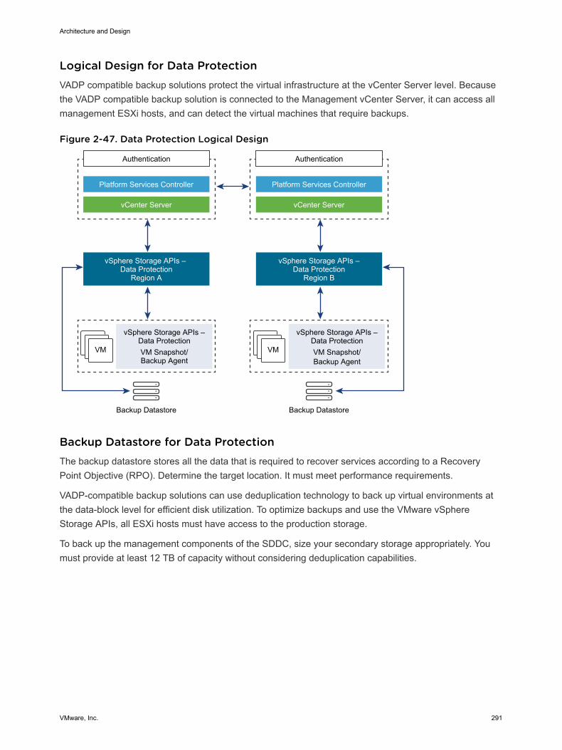
Logical Design for Data Protection VADP compatible backup solutions protect the virtual infrastructure at the vCenter Server level. Becausethe VADP compatible backup solution is connected to the Management vCenter Server, it can access allmanagement ESXi hosts, and can detect the virtual machines that require backups.
Figure 2-47. Data Protection Logical Design
VM VM
Authentication
Platform Services Controller
vCenter Server
vSphere Storage APIs – Data Protection
Region A
vSphere Storage APIs –Data ProtectionVM Snapshot/Backup Agent
Backup Datastore
Authentication
Platform Services Controller
vCenter Server
vSphere Storage APIs –Data Protection
Region B
vSphere Storage APIs –Data ProtectionVM Snapshot/Backup Agent
Backup Datastore
Backup Datastore for Data Protection The backup datastore stores all the data that is required to recover services according to a RecoveryPoint Objective (RPO). Determine the target location. It must meet performance requirements.
VADP-compatible backup solutions can use deduplication technology to back up virtual environments atthe data-block level for efficient disk utilization. To optimize backups and use the VMware vSphereStorage APIs, all ESXi hosts must have access to the production storage.
To back up the management components of the SDDC, size your secondary storage appropriately. Youmust provide at least 12 TB of capacity without considering deduplication capabilities.
Architecture and Design
VMware, Inc. 291
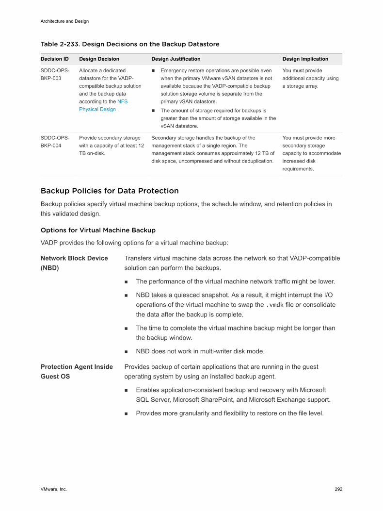
Table 2-233. Design Decisions on the Backup Datastore
Decision ID Design Decision Design Justification Design Implication
SDDC-OPS-BKP-003
Allocate a dedicateddatastore for the VADP-compatible backup solutionand the backup dataaccording to the NFSPhysical Design .
n Emergency restore operations are possible evenwhen the primary VMware vSAN datastore is notavailable because the VADP-compatible backupsolution storage volume is separate from theprimary vSAN datastore.
n The amount of storage required for backups isgreater than the amount of storage available in thevSAN datastore.
You must provideadditional capacity usinga storage array.
SDDC-OPS-BKP-004
Provide secondary storagewith a capacity of at least 12TB on-disk.
Secondary storage handles the backup of themanagement stack of a single region. Themanagement stack consumes approximately 12 TB ofdisk space, uncompressed and without deduplication.
You must provide moresecondary storagecapacity to accommodateincreased diskrequirements.
Backup Policies for Data Protection Backup policies specify virtual machine backup options, the schedule window, and retention policies inthis validated design.
Options for Virtual Machine Backup
VADP provides the following options for a virtual machine backup:
Network Block Device(NBD)
Transfers virtual machine data across the network so that VADP-compatiblesolution can perform the backups.
n The performance of the virtual machine network traffic might be lower.
n NBD takes a quiesced snapshot. As a result, it might interrupt the I/Ooperations of the virtual machine to swap the .vmdk file or consolidatethe data after the backup is complete.
n The time to complete the virtual machine backup might be longer thanthe backup window.
n NBD does not work in multi-writer disk mode.
Protection Agent InsideGuest OS
Provides backup of certain applications that are running in the guestoperating system by using an installed backup agent.
n Enables application-consistent backup and recovery with MicrosoftSQL Server, Microsoft SharePoint, and Microsoft Exchange support.
n Provides more granularity and flexibility to restore on the file level.
Architecture and Design
VMware, Inc. 292

Table 2-234. Design Decisions on Virtual Machine Transport Mode
Decision ID Design Decision Design Justification Design Implication
SDDC-OPS-BKP-005
Use HotAdd to back up virtualmachines.
HotAdd optimizes and speeds up virtualmachine backups, and does not impactthe vSphere management network.
All ESXi hosts must beconnected to the virtual machinedatastores.
SDDC-OPS-BKP-006
Use the VADP solution agentfor backups of the MicrosoftSQL Server.
You can restore application data insteadof entire virtual machines.
You must install and maintain theVADP solution agent.
Schedule Window
Even though VADP uses the Changed Block Tracking technology to optimize the backup data, to avoidany business impact, do not use a backup window when the production storage is in high demand.
Table 2-235. Design Decisions on Backup Schedule
Decision ID Design Decision Design Justification Design Implication
SDDC-OPS-BKP-007
Schedule dailybackups.
You can recover virtual machine data that isat most a day old.
You lose data that changed since the lastbackup 24 hours ago.
SDDC-OPS-BKP-008
Schedule backupsoutside theproduction peaktimes.
Backups occur when the system is under thelowest load. Make sure that backups arecompleted in the shortest time possible withthe smallest risk of errors.
n The non-peak time to completebackups might be limited.
n Backup duration also depends onstorage I/O throughput.
Retention Policies
Retention policies are properties of a backup job. If you group virtual machines by business priority, youcan set the retention requirements according to the business priority.
Table 2-236. Design Decisions on Backup Retention Policies
Decision ID Design Decision Design Justification Design Implication
SDDC-OPS-BKP-009
Retain backups for atleast 3 days.
Keeping 3 days of backups enablesadministrators to restore the managementapplications to a state within the last 72 hours.
Depending on the rate of change invirtual machines, backup retentionpolicy can increase the storage targetsize.
SDDC-OPS-BKP-010
Retain backups forcross-regionreplicated backupjobs for at least 1 day.
Keeping 1 day of a backup for replicated jobsenables administrators, in the event of adisaster recovery situation in which failoverwas unsuccessful, to restore their region-independent applications to a state within thelast 24 hours.
You lost data that has changed sincethe last backup 24 hours ago. This dataloss also increases the storagerequirements for the backup solution ina multi-region configuration.
Information Security and Access Control for Data Protection You use a service account for authentication and authorization of a VADP-compatible backup solution forbackup and restore operations.
Architecture and Design
VMware, Inc. 293
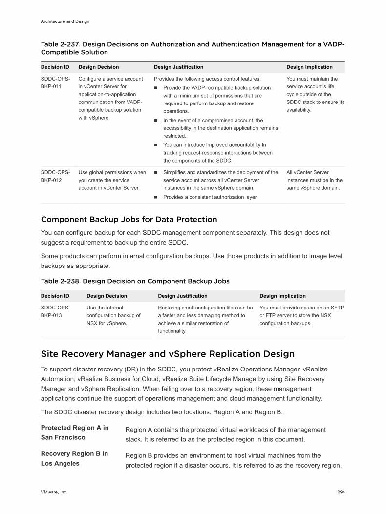
Table 2-237. Design Decisions on Authorization and Authentication Management for a VADP-Compatible Solution
Decision ID Design Decision Design Justification Design Implication
SDDC-OPS-BKP-011
Configure a service accountin vCenter Server forapplication-to-applicationcommunication from VADP-compatible backup solutionwith vSphere.
Provides the following access control features:
n Provide the VADP- compatible backup solutionwith a minimum set of permissions that arerequired to perform backup and restoreoperations.
n In the event of a compromised account, theaccessibility in the destination application remainsrestricted.
n You can introduce improved accountability intracking request-response interactions betweenthe components of the SDDC.
You must maintain theservice account's lifecycle outside of theSDDC stack to ensure itsavailability.
SDDC-OPS-BKP-012
Use global permissions whenyou create the serviceaccount in vCenter Server.
n Simplifies and standardizes the deployment of theservice account across all vCenter Serverinstances in the same vSphere domain.
n Provides a consistent authorization layer.
All vCenter Serverinstances must be in thesame vSphere domain.
Component Backup Jobs for Data Protection You can configure backup for each SDDC management component separately. This design does notsuggest a requirement to back up the entire SDDC.
Some products can perform internal configuration backups. Use those products in addition to image levelbackups as appropriate.
Table 2-238. Design Decision on Component Backup Jobs
Decision ID Design Decision Design Justification Design Implication
SDDC-OPS-BKP-013
Use the internalconfiguration backup ofNSX for vSphere.
Restoring small configuration files can bea faster and less damaging method toachieve a similar restoration offunctionality.
You must provide space on an SFTPor FTP server to store the NSXconfiguration backups.
Site Recovery Manager and vSphere Replication DesignTo support disaster recovery (DR) in the SDDC, you protect vRealize Operations Manager, vRealizeAutomation, vRealize Business for Cloud, vRealize Suite Lifecycle Managerby using Site RecoveryManager and vSphere Replication. When failing over to a recovery region, these managementapplications continue the support of operations management and cloud management functionality.
The SDDC disaster recovery design includes two locations: Region A and Region B.
Protected Region A inSan Francisco
Region A contains the protected virtual workloads of the managementstack. It is referred to as the protected region in this document.
Recovery Region B inLos Angeles
Region B provides an environment to host virtual machines from theprotected region if a disaster occurs. It is referred to as the recovery region.
Architecture and Design
VMware, Inc. 294
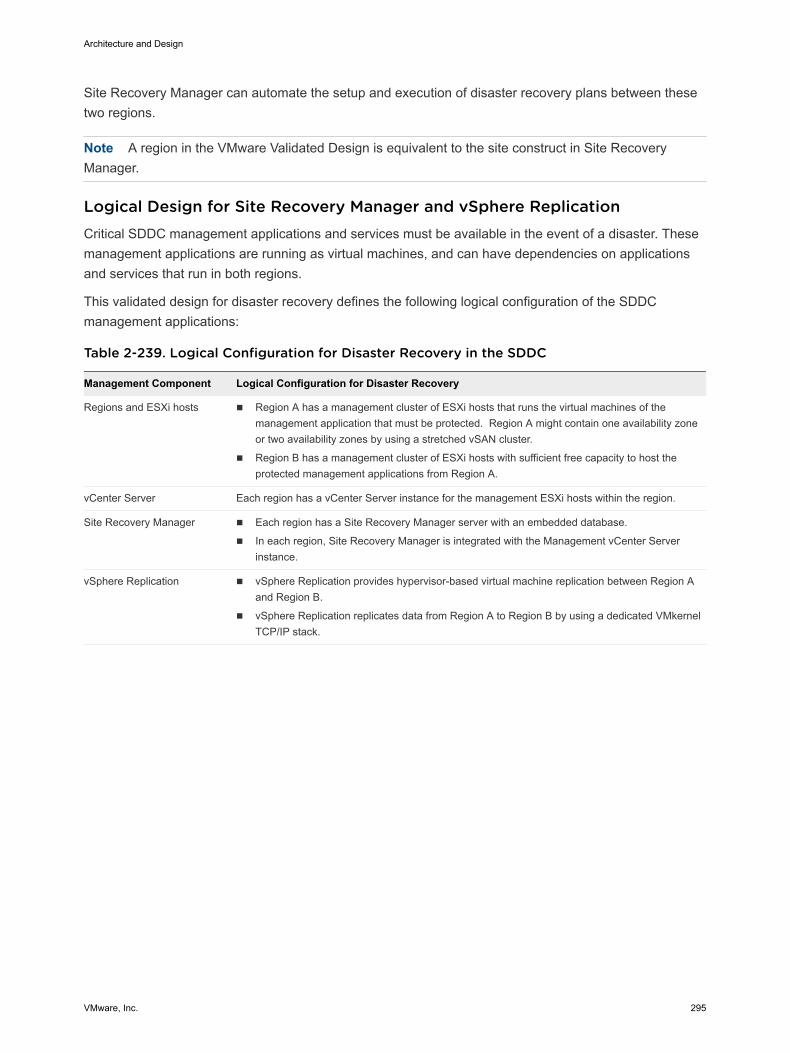
Site Recovery Manager can automate the setup and execution of disaster recovery plans between thesetwo regions.
Note A region in the VMware Validated Design is equivalent to the site construct in Site RecoveryManager.
Logical Design for Site Recovery Manager and vSphere ReplicationCritical SDDC management applications and services must be available in the event of a disaster. Thesemanagement applications are running as virtual machines, and can have dependencies on applicationsand services that run in both regions.
This validated design for disaster recovery defines the following logical configuration of the SDDCmanagement applications:
Table 2-239. Logical Configuration for Disaster Recovery in the SDDC
Management Component Logical Configuration for Disaster Recovery
Regions and ESXi hosts n Region A has a management cluster of ESXi hosts that runs the virtual machines of themanagement application that must be protected. Region A might contain one availability zoneor two availability zones by using a stretched vSAN cluster.
n Region B has a management cluster of ESXi hosts with sufficient free capacity to host theprotected management applications from Region A.
vCenter Server Each region has a vCenter Server instance for the management ESXi hosts within the region.
Site Recovery Manager n Each region has a Site Recovery Manager server with an embedded database.
n In each region, Site Recovery Manager is integrated with the Management vCenter Serverinstance.
vSphere Replication n vSphere Replication provides hypervisor-based virtual machine replication between Region Aand Region B.
n vSphere Replication replicates data from Region A to Region B by using a dedicated VMkernelTCP/IP stack.
Architecture and Design
VMware, Inc. 295
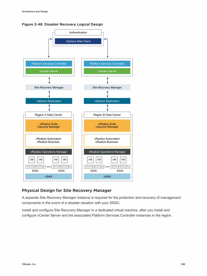
Figure 2-48. Disaster Recovery Logical Design
VM VM VM VM VM VM VM VM
Authentication
Platform Services Controller
vCenter Server
vSphere Web Client
Site Recovery Manager
vSphere Replication
Region A Data Center
vSAN
vRealize AutomationvRealize Business
Platform Services Controller
vCenter Server
Site Recovery Manager
vSphere Replication
vRealize Operations Manager vRealize Operations Manager
ESXi ESXi
Region B Data Center
vRealize Suite Lifecycle Manager
vRealize Suite Lifecycle Manager
vSAN
vRealize AutomationvRealize Business
ESXi ESXi
Physical Design for Site Recovery ManagerA separate Site Recovery Manager instance is required for the protection and recovery of managementcomponents in the event of a disaster situation with your SDDC.
Install and configure Site Recovery Manager in a dedicated virtual machine, after you install andconfigure vCenter Server and the associated Platform Services Controller instances in the region.
Architecture and Design
VMware, Inc. 296
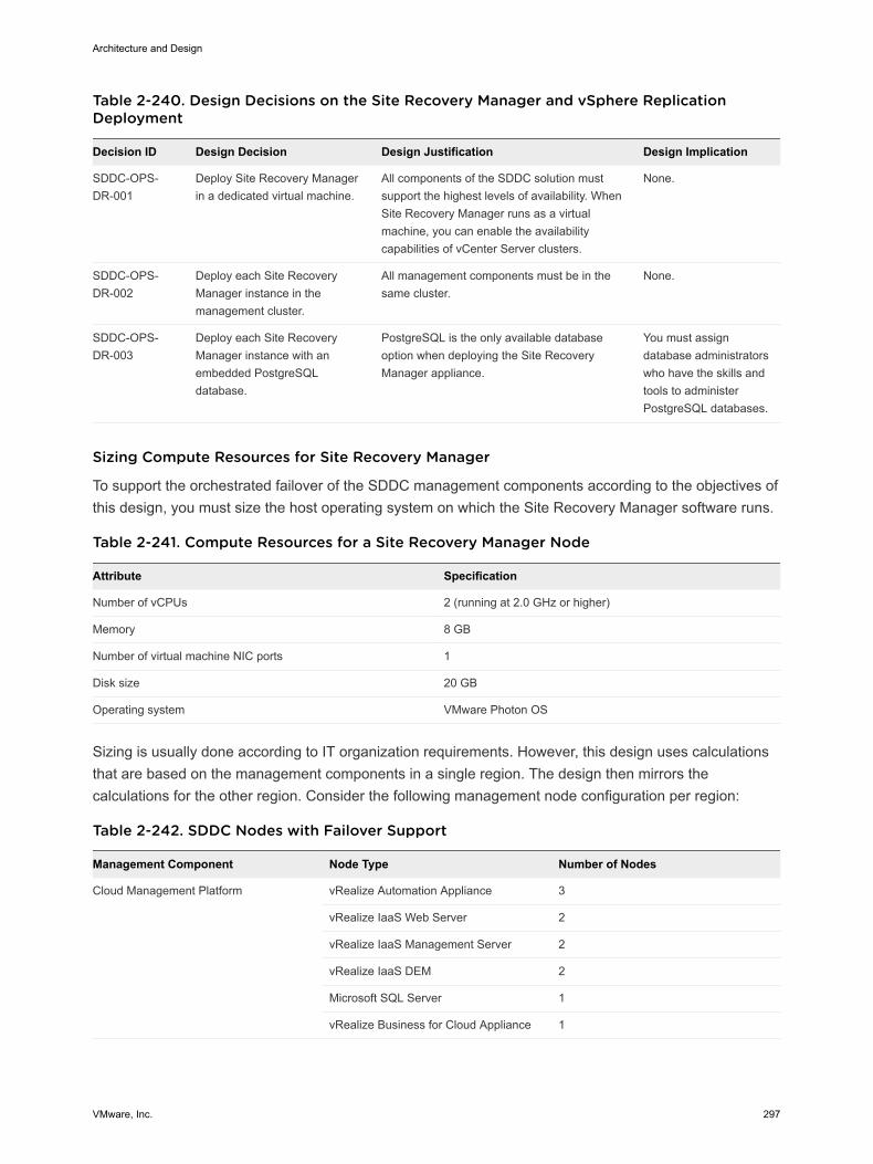
Table 2-240. Design Decisions on the Site Recovery Manager and vSphere ReplicationDeployment
Decision ID Design Decision Design Justification Design Implication
SDDC-OPS-DR-001
Deploy Site Recovery Managerin a dedicated virtual machine.
All components of the SDDC solution mustsupport the highest levels of availability. WhenSite Recovery Manager runs as a virtualmachine, you can enable the availabilitycapabilities of vCenter Server clusters.
None.
SDDC-OPS-DR-002
Deploy each Site RecoveryManager instance in themanagement cluster.
All management components must be in thesame cluster.
None.
SDDC-OPS-DR-003
Deploy each Site RecoveryManager instance with anembedded PostgreSQLdatabase.
PostgreSQL is the only available databaseoption when deploying the Site RecoveryManager appliance.
You must assigndatabase administratorswho have the skills andtools to administerPostgreSQL databases.
Sizing Compute Resources for Site Recovery Manager
To support the orchestrated failover of the SDDC management components according to the objectives ofthis design, you must size the host operating system on which the Site Recovery Manager software runs.
Table 2-241. Compute Resources for a Site Recovery Manager Node
Attribute Specification
Number of vCPUs 2 (running at 2.0 GHz or higher)
Memory 8 GB
Number of virtual machine NIC ports 1
Disk size 20 GB
Operating system VMware Photon OS
Sizing is usually done according to IT organization requirements. However, this design uses calculationsthat are based on the management components in a single region. The design then mirrors thecalculations for the other region. Consider the following management node configuration per region:
Table 2-242. SDDC Nodes with Failover Support
Management Component Node Type Number of Nodes
Cloud Management Platform vRealize Automation Appliance 3
vRealize IaaS Web Server 2
vRealize IaaS Management Server 2
vRealize IaaS DEM 2
Microsoft SQL Server 1
vRealize Business for Cloud Appliance 1
Architecture and Design
VMware, Inc. 297
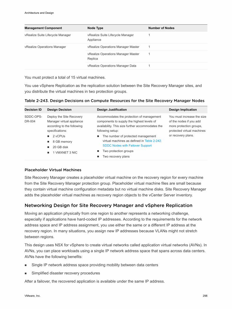
Management Component Node Type Number of Nodes
vRealize Suite Lifecycle Manager vRealize Suite Lifecycle ManagerAppliance
1
vRealize Operations Manager vRealize Operations Manager Master 1
vRealize Operations Manager MasterReplica
1
vRealize Operations Manager Data 1
You must protect a total of 15 virtual machines.
You use vSphere Replication as the replication solution between the Site Recovery Manager sites, andyou distribute the virtual machines in two protection groups.
Table 2-243. Design Decisions on Compute Resources for the Site Recovery Manager Nodes
Decision ID Design Decision Design Justification Design Implication
SDDC-OPS-DR-004
Deploy the Site RecoveryManager virtual applianceaccording to the followingspecifications:
n 2 vCPUs
n 8 GB memory
n 20 GB disk
n 1 VMXNET 3 NIC
Accommodates the protection of managementcomponents to supply the highest levels ofavailability. This size further accommodates thefollowing setup:
n The number of protected managementvirtual machines as defined in Table 2-242.SDDC Nodes with Failover Support
n Two protection groups
n Two recovery plans
You must increase the sizeof the nodes if you addmore protection groups,protected virtual machinesor recovery plans.
Placeholder Virtual Machines
Site Recovery Manager creates a placeholder virtual machine on the recovery region for every machinefrom the Site Recovery Manager protection group. Placeholder virtual machine files are small becausethey contain virtual machine configuration metadata but no virtual machine disks. Site Recovery Manageradds the placeholder virtual machines as recovery region objects to the vCenter Server inventory.
Networking Design for Site Recovery Manager and vSphere ReplicationMoving an application physically from one region to another represents a networking challenge,especially if applications have hard-coded IP addresses. According to the requirements for the networkaddress space and IP address assignment, you use either the same or a different IP address at therecovery region. In many situations, you assign new IP addresses because VLANs might not stretchbetween regions.
This design uses NSX for vSphere to create virtual networks called application virtual networks (AVNs). InAVNs, you can place workloads using a single IP network address space that spans across data centers.AVNs have the following benefits:
n Single IP network address space providing mobility between data centers
n Simplified disaster recovery procedures
After a failover, the recovered application is available under the same IP address.
Architecture and Design
VMware, Inc. 298
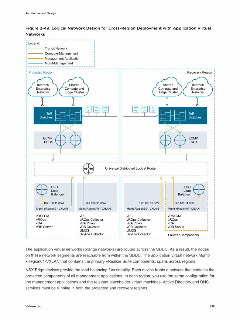
Figure 2-49. Logical Network Design for Cross-Region Deployment with Application VirtualNetworks
PSC
OSSRM
OSVC
OSPSC
OSSRM
OSVC
OS
Protected Region
ECMPESGs
ToRSwitches
Internet/EnterpriseNetwork
Mgmt-Management
Compute-Management
Legend:
Shared Compute and Edge Cluster
192.168.11.0/24
Transit Network
Management Application
vRLIvROps CollectorvRA ProxyvRB CollectorUMDSSkyline Collector
vRSLCMvROpsvRAvRB Server
ESGLoadBalancer
Mgmt-xRegion01-VXLAN
192.168.31.0/24
Mgmt-RegionА01-VXLAN
Universal Distributed Logical Router
Recovery Region
ECMPESGs
ToR Switches
vRLIvROps CollectorvRA ProxyvRB CollectorUMDSSkyline Collector
vRSLCMvROpsvRAvRB Server
192.168.32.0/24
Mgmt-RegionB01-VXLAN
192.168.11.0/24
ESGLoad
Balancer
Mgmt-xRegion01-VXLAN
Failover Components
Internet/EnterpriseNetwork
Shared Compute and Edge Cluster
The application virtual networks (orange networks) are routed across the SDDC. As a result, the nodeson these network segments are reachable from within the SDDC. The application virtual network Mgmt-xRegion01-VXLAN that contains the primary vRealize Suite components, spans across regions.
NSX Edge devices provide the load balancing functionality. Each device fronts a network that contains theprotected components of all management applications. In each region, you use the same configuration forthe management applications and the relevant placeholder virtual machines. Active Directory and DNSservices must be running in both the protected and recovery regions.
Architecture and Design
VMware, Inc. 299
The virtual machines of Site Recovery Manager and vSphere Replication are on the VLAN backedmanagement network in each region.
Information Security and Access Control for Site Recovery Manager andvSphere ReplicationYou use a service account for authentication and authorization of Site Recovery Manager to vCenterServer for orchestrated disaster recovery of the SDDC.
Architecture and Design
VMware, Inc. 300
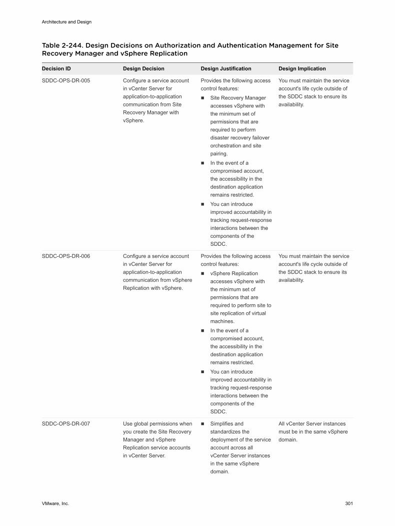
Table 2-244. Design Decisions on Authorization and Authentication Management for SiteRecovery Manager and vSphere Replication
Decision ID Design Decision Design Justification Design Implication
SDDC-OPS-DR-005 Configure a service accountin vCenter Server forapplication-to-applicationcommunication from SiteRecovery Manager withvSphere.
Provides the following accesscontrol features:
n Site Recovery Manageraccesses vSphere withthe minimum set ofpermissions that arerequired to performdisaster recovery failoverorchestration and sitepairing.
n In the event of acompromised account,the accessibility in thedestination applicationremains restricted.
n You can introduceimproved accountability intracking request-responseinteractions between thecomponents of theSDDC.
You must maintain the serviceaccount's life cycle outside ofthe SDDC stack to ensure itsavailability.
SDDC-OPS-DR-006 Configure a service accountin vCenter Server forapplication-to-applicationcommunication from vSphereReplication with vSphere.
Provides the following accesscontrol features:
n vSphere Replicationaccesses vSphere withthe minimum set ofpermissions that arerequired to perform site tosite replication of virtualmachines.
n In the event of acompromised account,the accessibility in thedestination applicationremains restricted.
n You can introduceimproved accountability intracking request-responseinteractions between thecomponents of theSDDC.
You must maintain the serviceaccount's life cycle outside ofthe SDDC stack to ensure itsavailability.
SDDC-OPS-DR-007 Use global permissions whenyou create the Site RecoveryManager and vSphereReplication service accountsin vCenter Server.
n Simplifies andstandardizes thedeployment of the serviceaccount across allvCenter Server instancesin the same vSpheredomain.
All vCenter Server instancesmust be in the same vSpheredomain.
Architecture and Design
VMware, Inc. 301
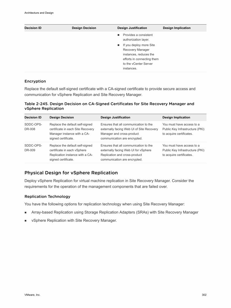
Decision ID Design Decision Design Justification Design Implication
n Provides a consistentauthorization layer.
n If you deploy more SiteRecovery Managerinstances, reduces theefforts in connecting themto the vCenter Serverinstances.
Encryption
Replace the default self-signed certificate with a CA-signed certificate to provide secure access andcommunication for vSphere Replication and Site Recovery Manager.
Table 2-245. Design Decision on CA-Signed Certificates for Site Recovery Manager andvSphere Replication
Decision ID Design Decision Design Justification Design Implication
SDDC-OPS-DR-008
Replace the default self-signedcertificate in each Site RecoveryManager instance with a CA-signed certificate.
Ensures that all communication to theexternally facing Web UI of Site RecoveryManager and cross-productcommunication are encrypted.
You must have access to aPublic Key Infrastructure (PKI)to acquire certificates.
SDDC-OPS-DR-009
Replace the default self-signedcertificate in each vSphereReplication instance with a CA-signed certificate.
Ensures that all communication to theexternally facing Web UI for vSphereReplication and cross-productcommunication are encrypted.
You must have access to aPublic Key Infrastructure (PKI)to acquire certificates.
Physical Design for vSphere ReplicationDeploy vSphere Replication for virtual machine replication in Site Recovery Manager. Consider therequirements for the operation of the management components that are failed over.
Replication Technology
You have the following options for replication technology when using Site Recovery Manager:
n Array-based Replication using Storage Replication Adapters (SRAs) with Site Recovery Manager
n vSphere Replication with Site Recovery Manager.
Architecture and Design
VMware, Inc. 302
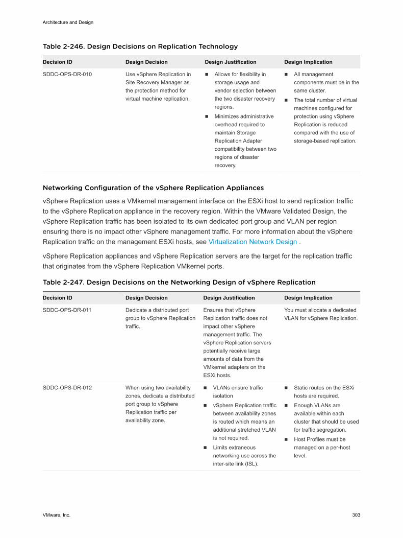
Table 2-246. Design Decisions on Replication Technology
Decision ID Design Decision Design Justification Design Implication
SDDC-OPS-DR-010 Use vSphere Replication inSite Recovery Manager asthe protection method forvirtual machine replication.
n Allows for flexibility instorage usage andvendor selection betweenthe two disaster recoveryregions.
n Minimizes administrativeoverhead required tomaintain StorageReplication Adaptercompatibility between tworegions of disasterrecovery.
n All managementcomponents must be in thesame cluster.
n The total number of virtualmachines configured forprotection using vSphereReplication is reducedcompared with the use ofstorage-based replication.
Networking Configuration of the vSphere Replication Appliances
vSphere Replication uses a VMkernel management interface on the ESXi host to send replication trafficto the vSphere Replication appliance in the recovery region. Within the VMware Validated Design, thevSphere Replication traffic has been isolated to its own dedicated port group and VLAN per regionensuring there is no impact other vSphere management traffic. For more information about the vSphereReplication traffic on the management ESXi hosts, see Virtualization Network Design .
vSphere Replication appliances and vSphere Replication servers are the target for the replication trafficthat originates from the vSphere Replication VMkernel ports.
Table 2-247. Design Decisions on the Networking Design of vSphere Replication
Decision ID Design Decision Design Justification Design Implication
SDDC-OPS-DR-011 Dedicate a distributed portgroup to vSphere Replicationtraffic.
Ensures that vSphereReplication traffic does notimpact other vSpheremanagement traffic. ThevSphere Replication serverspotentially receive largeamounts of data from theVMkernel adapters on theESXi hosts.
You must allocate a dedicatedVLAN for vSphere Replication.
SDDC-OPS-DR-012 When using two availabilityzones, dedicate a distributedport group to vSphereReplication traffic peravailability zone.
n VLANs ensure trafficisolation
n vSphere Replication trafficbetween availability zonesis routed which means anadditional stretched VLANis not required.
n Limits extraneousnetworking use across theinter-site link (ISL).
n Static routes on the ESXihosts are required.
n Enough VLANs areavailable within eachcluster that should be usedfor traffic segregation.
n Host Profiles must bemanaged on a per-hostlevel.
Architecture and Design
VMware, Inc. 303
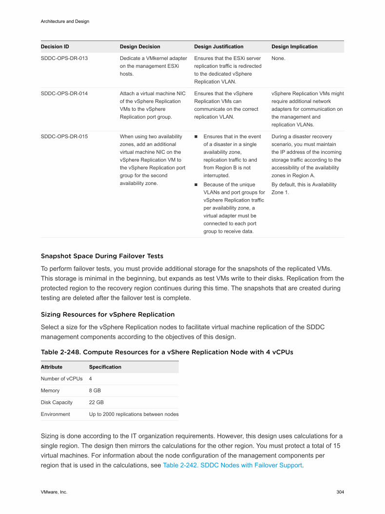
Decision ID Design Decision Design Justification Design Implication
SDDC-OPS-DR-013 Dedicate a VMkernel adapteron the management ESXihosts.
Ensures that the ESXi serverreplication traffic is redirectedto the dedicated vSphereReplication VLAN.
None.
SDDC-OPS-DR-014 Attach a virtual machine NICof the vSphere ReplicationVMs to the vSphereReplication port group.
Ensures that the vSphereReplication VMs cancommunicate on the correctreplication VLAN.
vSphere Replication VMs mightrequire additional networkadapters for communication onthe management andreplication VLANs.
SDDC-OPS-DR-015 When using two availabilityzones, add an additionalvirtual machine NIC on thevSphere Replication VM tothe vSphere Replication portgroup for the secondavailability zone.
n Ensures that in the eventof a disaster in a singleavailability zone,replication traffic to andfrom Region B is notinterrupted.
n Because of the uniqueVLANs and port groups forvSphere Replication trafficper availability zone, avirtual adapter must beconnected to each portgroup to receive data.
During a disaster recoveryscenario, you must maintainthe IP address of the incomingstorage traffic according to theaccessibility of the availabilityzones in Region A.
By default, this is AvailabilityZone 1.
Snapshot Space During Failover Tests
To perform failover tests, you must provide additional storage for the snapshots of the replicated VMs.This storage is minimal in the beginning, but expands as test VMs write to their disks. Replication from theprotected region to the recovery region continues during this time. The snapshots that are created duringtesting are deleted after the failover test is complete.
Sizing Resources for vSphere Replication
Select a size for the vSphere Replication nodes to facilitate virtual machine replication of the SDDCmanagement components according to the objectives of this design.
Table 2-248. Compute Resources for a vShere Replication Node with 4 vCPUs
Attribute Specification
Number of vCPUs 4
Memory 8 GB
Disk Capacity 22 GB
Environment Up to 2000 replications between nodes
Sizing is done according to the IT organization requirements. However, this design uses calculations for asingle region. The design then mirrors the calculations for the other region. You must protect a total of 15virtual machines. For information about the node configuration of the management components perregion that is used in the calculations, see Table 2-242. SDDC Nodes with Failover Support.
Architecture and Design
VMware, Inc. 304
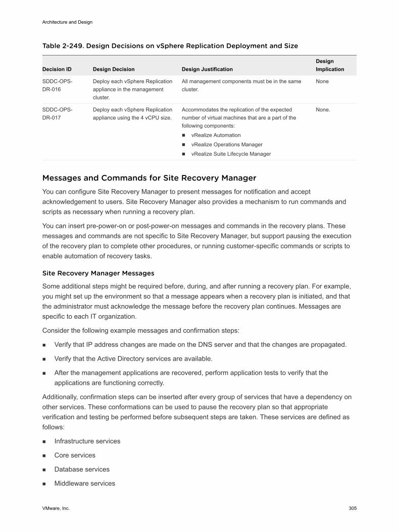
Table 2-249. Design Decisions on vSphere Replication Deployment and Size
Decision ID Design Decision Design JustificationDesignImplication
SDDC-OPS-DR-016
Deploy each vSphere Replicationappliance in the managementcluster.
All management components must be in the samecluster.
None
SDDC-OPS-DR-017
Deploy each vSphere Replicationappliance using the 4 vCPU size.
Accommodates the replication of the expectednumber of virtual machines that are a part of thefollowing components:
n vRealize Automation
n vRealize Operations Manager
n vRealize Suite Lifecycle Manager
None.
Messages and Commands for Site Recovery ManagerYou can configure Site Recovery Manager to present messages for notification and acceptacknowledgement to users. Site Recovery Manager also provides a mechanism to run commands andscripts as necessary when running a recovery plan.
You can insert pre-power-on or post-power-on messages and commands in the recovery plans. Thesemessages and commands are not specific to Site Recovery Manager, but support pausing the executionof the recovery plan to complete other procedures, or running customer-specific commands or scripts toenable automation of recovery tasks.
Site Recovery Manager Messages
Some additional steps might be required before, during, and after running a recovery plan. For example,you might set up the environment so that a message appears when a recovery plan is initiated, and thatthe administrator must acknowledge the message before the recovery plan continues. Messages arespecific to each IT organization.
Consider the following example messages and confirmation steps:
n Verify that IP address changes are made on the DNS server and that the changes are propagated.
n Verify that the Active Directory services are available.
n After the management applications are recovered, perform application tests to verify that theapplications are functioning correctly.
Additionally, confirmation steps can be inserted after every group of services that have a dependency onother services. These conformations can be used to pause the recovery plan so that appropriateverification and testing be performed before subsequent steps are taken. These services are defined asfollows:
n Infrastructure services
n Core services
n Database services
n Middleware services
Architecture and Design
VMware, Inc. 305
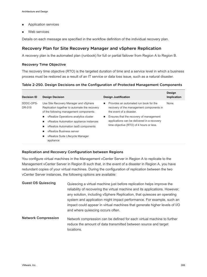
n Application services
n Web services
Details on each message are specified in the workflow definition of the individual recovery plan.
Recovery Plan for Site Recovery Manager and vSphere ReplicationA recovery plan is the automated plan (runbook) for full or partial failover from Region A to Region B.
Recovery Time Objective
The recovery time objective (RTO) is the targeted duration of time and a service level in which a businessprocess must be restored as a result of an IT service or data loss issue, such as a natural disaster.
Table 2-250. Design Decisions on the Configuration of Protected Management Components
Decision ID Design Decision Design JustificationDesignImplication
SDDC-OPS-DR-018
Use Site Recovery Manager and vSphereReplication together to automate the recoveryof the following management components:
n vRealize Operations analytics cluster
n vRealize Automation appliance instances
n vRealize Automation IaaS components
n vRealize Business server
n vRealize Suite Lifecycle Managerappliance
n Provides an automated run book for therecovery of the management components inthe event of a disaster.
n Ensures that the recovery of managementapplications can be delivered in a recoverytime objective (RTO) of 4 hours or less.
None.
Replication and Recovery Configuration between Regions
You configure virtual machines in the Management vCenter Server in Region A to replicate to theManagement vCenter Server in Region B such that, in the event of a disaster in Region A, you haveredundant copies of your virtual machines. During the configuration of replication between the twovCenter Server instances, the following options are available:
Guest OS Quiescing Quiescing a virtual machine just before replication helps improve thereliability of recovering the virtual machine and its applications. However,any solution, including vSphere Replication, that quiesces an operatingsystem and application might impact performance. For example, such animpact could appear in virtual machines that generate higher levels of I/Oand where quiescing occurs often.
Network Compression Network compression can be defined for each virtual machine to furtherreduce the amount of data transmitted between source and targetlocations.
Architecture and Design
VMware, Inc. 306
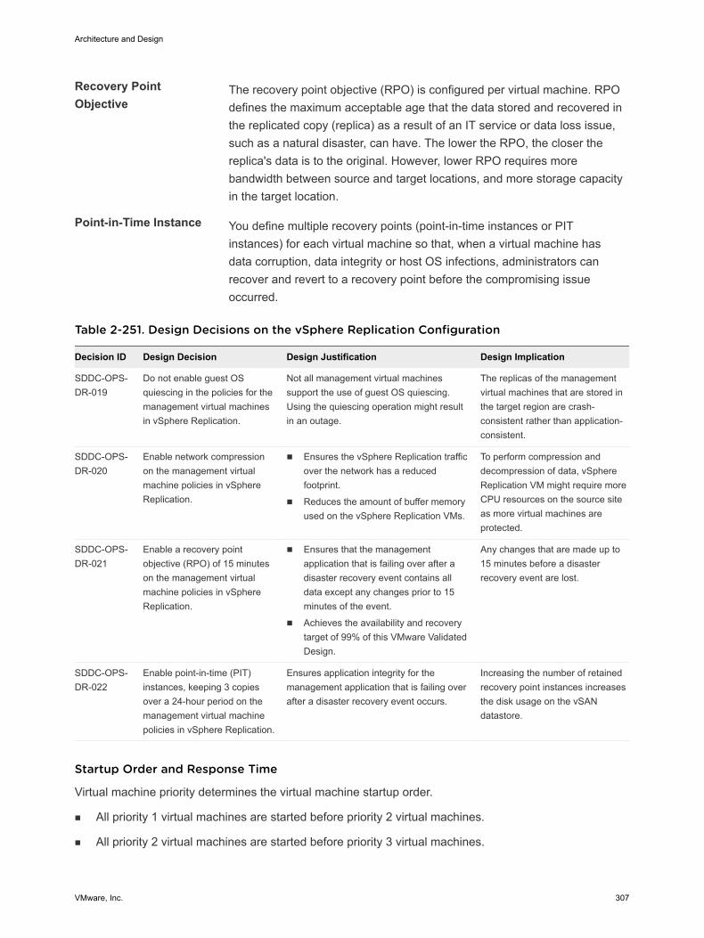
Recovery PointObjective
The recovery point objective (RPO) is configured per virtual machine. RPOdefines the maximum acceptable age that the data stored and recovered inthe replicated copy (replica) as a result of an IT service or data loss issue,such as a natural disaster, can have. The lower the RPO, the closer thereplica's data is to the original. However, lower RPO requires morebandwidth between source and target locations, and more storage capacityin the target location.
Point-in-Time Instance You define multiple recovery points (point-in-time instances or PITinstances) for each virtual machine so that, when a virtual machine hasdata corruption, data integrity or host OS infections, administrators canrecover and revert to a recovery point before the compromising issueoccurred.
Table 2-251. Design Decisions on the vSphere Replication Configuration
Decision ID Design Decision Design Justification Design Implication
SDDC-OPS-DR-019
Do not enable guest OSquiescing in the policies for themanagement virtual machinesin vSphere Replication.
Not all management virtual machinessupport the use of guest OS quiescing.Using the quiescing operation might resultin an outage.
The replicas of the managementvirtual machines that are stored inthe target region are crash-consistent rather than application-consistent.
SDDC-OPS-DR-020
Enable network compressionon the management virtualmachine policies in vSphereReplication.
n Ensures the vSphere Replication trafficover the network has a reducedfootprint.
n Reduces the amount of buffer memoryused on the vSphere Replication VMs.
To perform compression anddecompression of data, vSphereReplication VM might require moreCPU resources on the source siteas more virtual machines areprotected.
SDDC-OPS-DR-021
Enable a recovery pointobjective (RPO) of 15 minuteson the management virtualmachine policies in vSphereReplication.
n Ensures that the managementapplication that is failing over after adisaster recovery event contains alldata except any changes prior to 15minutes of the event.
n Achieves the availability and recoverytarget of 99% of this VMware ValidatedDesign.
Any changes that are made up to15 minutes before a disasterrecovery event are lost.
SDDC-OPS-DR-022
Enable point-in-time (PIT)instances, keeping 3 copiesover a 24-hour period on themanagement virtual machinepolicies in vSphere Replication.
Ensures application integrity for themanagement application that is failing overafter a disaster recovery event occurs.
Increasing the number of retainedrecovery point instances increasesthe disk usage on the vSANdatastore.
Startup Order and Response Time
Virtual machine priority determines the virtual machine startup order.
n All priority 1 virtual machines are started before priority 2 virtual machines.
n All priority 2 virtual machines are started before priority 3 virtual machines.
Architecture and Design
VMware, Inc. 307
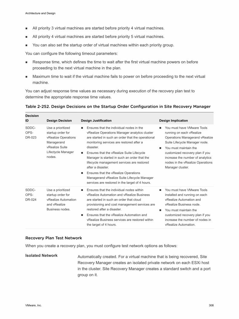
n All priority 3 virtual machines are started before priority 4 virtual machines.
n All priority 4 virtual machines are started before priority 5 virtual machines.
n You can also set the startup order of virtual machines within each priority group.
You can configure the following timeout parameters:
n Response time, which defines the time to wait after the first virtual machine powers on beforeproceeding to the next virtual machine in the plan.
n Maximum time to wait if the virtual machine fails to power on before proceeding to the next virtualmachine.
You can adjust response time values as necessary during execution of the recovery plan test todetermine the appropriate response time values.
Table 2-252. Design Decisions on the Startup Order Configuration in Site Recovery Manager
DecisionID Design Decision Design Justification Design Implication
SDDC-OPS-DR-023
Use a prioritizedstartup order forvRealize OperationsManagerandvRealize SuiteLifectycle Managernodes.
n Ensures that the individual nodes in thevRealize Operations Manager analytics clusterare started in such an order that the operationalmonitoring services are restored after adisaster.
n Ensures that the vRealize Suite LifecycleManager is started in such an order that thelifecycle management services are restoredafter a disaster.
n Ensures that the vRealize OperationsManagerand vRealize Suite Lifecycle Managerservices are restored in the target of 4 hours.
n You must have VMware Toolsrunning on each vRealizeOperations Managerand vRealizeSuite Lifecycle Manager node.
n You must maintain thecustomized recovery plan if youincrease the number of analyticsnodes in the vRealize OperationsManager cluster.
SDDC-OPS-DR-024
Use a prioritizedstartup order forvRealize Automationand vRealizeBusiness nodes.
n Ensures that the individual nodes withinvRealize Automation and vRealize Businessare started in such an order that cloudprovisioning and cost management services arerestored after a disaster.
n Ensures that the vRealize Automation andvRealize Business services are restored withinthe target of 4 hours.
n You must have VMware Toolsinstalled and running on eachvRealize Automation andvRealize Business node.
n You must maintain thecustomized recovery plan if youincrease the number of nodes invRealize Automation.
Recovery Plan Test Network
When you create a recovery plan, you must configure test network options as follows:
Isolated Network Automatically created. For a virtual machine that is being recovered, SiteRecovery Manager creates an isolated private network on each ESXi hostin the cluster. Site Recovery Manager creates a standard switch and a portgroup on it.
Architecture and Design
VMware, Inc. 308

A limitation of this automatic configuration is that a virtual machine that isconnected to the isolated port group on one ESXi host cannot communicatewith a virtual machine on another ESXi host. This option limits testingscenarios and provides an isolated test network only for basic virtualmachine testing.
Port Group Selecting an existing port group provides a more granular configuration tomeet your testing requirements. If you want virtual machines across ESXihosts to communicate, use a standard or distributed switch with uplinks tothe production network, and create a port group on the switch that hastagging with a non-routable VLAN enabled. In this way, you isolate thenetwork. It is not connected to other production networks.
Because the application virtual networks for failover are fronted by a load balancer, you can use therecovery plan production network as this provides realistic verification of a recovered managementapplication.
Table 2-253. Design Decisions on the Recovery Plan Test Network
Decision ID Design Decision Design Justification Design Implication
SDDC-OPS-DR-025
Use the targetrecoveryproduction networkfor testing.
The design of the applicationvirtual networks supports their useas recovery plan test networks.
This allows the re-use of existingnetworks.
During recovery testing, a management application isnot reachable using its production FQDN. Access theapplication using its VIP address or assign a temporaryFQDN for testing.
Note that this approach results in certificate warningsbecause the assigned temporary host name and thehost name in the certificate mismatch.
Architecture and Design
VMware, Inc. 309