aries-at vacuum vessel design approach and...
TRANSCRIPT

Page 1
ARIES-AT Vacuum Vessel Design Approach and Cost Assessment
By Lester M. Waganer1, Laila X. El-Guebaly2, and Xueren Wang2
(1) The Boeing Company2, St. Louis, MO (2) University of Wisconsin, Madison, WI
(3) University of California, San Diego, San Diego, CA and
The ARIES Team
Abstract The design of the ARIES-AT vacuum vessel is established by the requirements to maintain a high quality vacuum for the tokamak plasma, enclose and support the power core high-temperature elements, provide supplemental core shielding and cooling, act as a heat sink during loss of coolant/flow accident, and allow modular horizontal replacement of complete power core sectors for a minimum cost solution. The preliminary design approach is defined for the ARIES-AT vacuum vessel along with an explanation of the important design considerations. The design fully supports the high-level system requirements. A detailed cost assessment was accomplished that affirmed the vacuum vessel could be fabricated for a cost-competitive capital cost.
Vacuum Vessel Design Philosophy The design for the ARIES-AT1 power core is based on the evolving physics and engineering understanding of advanced tokamak systems. The database is supported by ongoing experiments and technology developments throughout the world. The ARIES series of power plant designs draw and improve upon these advances to conceptualize and define an embodiment of a viable commercial fusion electrical generating power plant. Likewise the vacuum vessel subsystem uses the best of the existing and proposed designs and solutions to achieve an integrated and synergistic solution.
Vacuum Vessel Design Approach Preliminary Definition - The primary function of the vacuum vessel is to contain the high-level vacuum necessary to achieve and maintain a high-quality fusion plasma. The vessel must be a leak-tight structure with a large port for each of the core sectors between TF coils to allow maintenance access for removal and replacement of complete sectors of the power core2. The vacuum vessel must also contain and support the power core thermal elements of the blanket, shield, and divertor. Conceivably the vacuum vessel could encompass the toroidal field (TF) and poloidal field (PF) coils. If that were the case, the requirements for the thermal and neutron shielding of the high and low temperature core shields would be quite severe to assure the coils would not be damaged by the high energy neutrons. Instead, it was decided to locate the vacuum vessel between the high-temperature core and the coils. This location of the vacuum vessel could provide the additional neutron shielding yet the vacuum vessel would be a lifetime

Page 2
Figure 1. Preliminary power core arrangement
core element. Low temperature water circulating between the vacuum vessel structural walls can remove any waste heat not contained and used by the high-temperature power core.
The preliminary thickness of the power core elements and the coil system surrounding the initial plasma equilibrium field line plots initiated the definition of the power core elements. Nominal thicknesses and material allocations were assigned based upon previous similar design solutions. Design assumptions and CAD models were refined as neutronic models were constructed and analyzed. Preliminary inboard, outboard and vertical material builds3 were defined and refined to yield a suitable, balanced solutions for surface and volume heating fluxes, burnup fractions, tritium breeding ratio, and estimated component operational lifetimes. These radial and vertical build definitions were used to generally define the possible envelope of the vacuum vessel. Figure 1 schematically illustrates the space available for the vacuum vessel in the inboard and outboard regions. The plasma is not shown in this figure.

Page 3
The component adjacent to the plasma inboard and outboard is the first wall and inner blanket, both of which are limited lifetime components. Likewise the divertor (not shown) will be a limited-lifetime component. Since there is a significant amount of neutron flux on the outboard region, a second blanket3 is added in this outboard region to provide the required tritium breeding. Due to the significant neutron attenuation by the first blanket region, the second blanket can be designed as a life-of-plant component. The next layer away from the plasma is devoted to shielding the neutrons and extracting a major amount of the remaining thermal energy not recovered by the blanket components. The level of thermal energy recovered in this shield region was sufficient to justify operating the shield at the same high temperature as the blankets and recover high quality heat from the shield. Thus all core elements inside the vacuum vessel operate at high temperature (above 800°C).
The simultaneous replacement of all life-limited components is highly desirable for the inboard first wall/blanket, outboard first wall/blanket, and the divertor to significantly improve the maintainability and availability associated with the power core.
Since the plasma is a double-null plasma and the divertors are slot divertors, there is no credible means to provide a structural element bridging the inner and outer blanket regions to form an integral structural element. This structural capability is necessary to allow the removal of all the life-limited structure in a single integral piece. To provide the necessary structural integrity of the core sector, the shield was designed to also serve as the sector primary structural member. This would allow the removal of a complete sector of the power core. However, this approach does require removal of the life-of-plant components, such as the second outboard blanket and the high-temperature shield. Different scenarios relating to replacement schemes and refurbishment approaches were assessed4 in an ARIES-AT maintenance task. The recommended maintenance approach is to remove eight of the sixteen sectors every 2 years and immediately replace these sectors with refurbished sectors previously removed and refurbished, off line, during normal operation.
To meet both the neutronic and thermal requirements to protect the coils, the combination of the first wall, blanket, shield, and vacuum vessel must be sufficiently neutronically dense to protect the TF coil superconductor to the level of 1019 n/cm2 (En >0.1 MeV) over the lifetime of the plant. The evolving design of the first wall, blanket, and shield to maximize the conversion of the high-energy neutrons into tritium and thermal energy production yielded a highly efficient design that enabled a rather simple and cost effective vacuum vessel design. The design approach adopted was a double-walled, low-activation, ferritic steel (such as F82H or ORNL 9Cr-2WVTa), filled with water and tungsten carbide (WC) spheres as additional shielding material. This approach will also yield a reasonable, cost-effective fabrication cost.
To summarize the preliminary definition, the vacuum vessel must contain a high quality vacuum, contain and support all high-temperature power core elements (but not the coils), provide supplemental shielding and cooling, and provide sixteen large vacuum ports for horizontal sector replacement for a reasonable capital cost.
Conceptual Design Definition – The preliminary vacuum vessel definition refined the parameter and option design space to accomplish the overall system requirements. The next step was to refine the vacuum vessel geometry within the bounds and constraints of the evolving plasma shape and the other power core elements. Computer aided design (CAD) models were constructed to accurately define and assess design and geometry options and constraints.

Page 4
Figure 2. Cross Section of ARIES-AT Power Core Configuration
Figure 2 illustrates a CAD cross-section of the ARIES-AT power core that incorporates the requirements and constraints outlined in the preliminary vacuum vessel definition.
Page 5
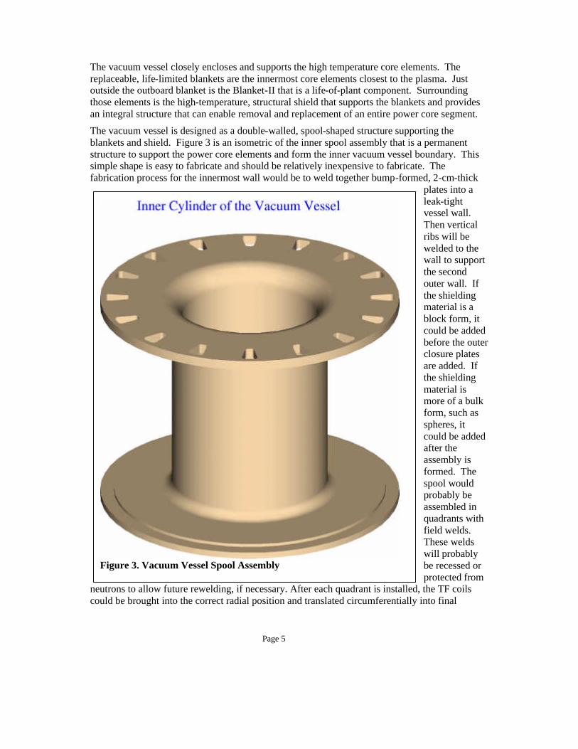
Figure 3. Vacuum Vessel Spool Assembly
The vacuum vessel closely encloses and supports the high temperature core elements. The replaceable, life-limited blankets are the innermost core elements closest to the plasma. Just outside the outboard blanket is the Blanket-II that is a life-of-plant component. Surrounding those elements is the high-temperature, structural shield that supports the blankets and provides an integral structure that can enable removal and replacement of an entire power core segment.
The vacuum vessel is designed as a double-walled, spool-shaped structure supporting the blankets and shield. Figure 3 is an isometric of the inner spool assembly that is a permanent structure to support the power core elements and form the inner vacuum vessel boundary. This simple shape is easy to fabricate and should be relatively inexpensive to fabricate. The fabrication process for the innermost wall would be to weld together bump-formed, 2-cm-thick
plates into a leak-tight vessel wall. Then vertical ribs will be welded to the wall to support the second outer wall. If the shielding material is a block form, it could be added before the outer closure plates are added. If the shielding material is more of a bulk form, such as spheres, it could be added after the assembly is formed. The spool would probably be assembled in quadrants with field welds. These welds will probably be recessed or protected from
neutrons to allow future rewelding, if necessary. After each quadrant is installed, the TF coils could be brought into the correct radial position and translated circumferentially into final

Page 6
Figure 4. Vacuum vessel spool dimensions
Figure 5. Spool Structural Details
position. The final quadrant would require a tailored assembly procedure with an internal construction joint. Figure 4 shows the dimensions of the inner spool assembly.
As shown in Figure 5, thirty-two ribs will extend vertically in the cylindrical section to connect the inner and outer walls. These ribs will direct the flow of the water coolant vertically. Additional ribs will continue in the circular curved transition area and into the radial flange areas. Water coolant connections for each flow passage, not shown, will supply water coolant ingress and egress.
Outboard of the spool assembly, removable doors and frame assemblies are
required to complete the vacuum vessel assembly. The size of the core sector being removed defines the door opening over the height of the sector. The door is contoured to closely fit the outer surface of the shield, but allows sufficient space for vacuum conductance from top to bottom of the vessel. There also a requirement to provide space for plasma control coils on the inner surface of the vacuum vessel. The power core cross-section shown in Figure 2 shows the curvature of the door and the provision for the feedback coils. Figure 6 shows the elevation cross-section illustrating the door curvature. Figure 7 shows the cross-sections through the door at

Page 7
Figure 6. Cross-Section of Vacuum Vessel Door
Figure 7. Door Cross-Section Details
midplane and near the top of the door. The door is subdivided into several compartments to channel the cooling water flow from bottom to top. A thickness of 25 cm was chosen to give a reasonable shielding thickness and door stiffness. This number was refined during detailed design and analysis3. There is a step completely around the door to provide a positive door engagement and to help alleviate the neutron streaming around the door opening.
While the general curvature and height can be determined from the side view cross-section, the width of the door is determined from the plan view cross-section at various elevations through the door region. Figure 8 shows the plan view at the midplane of the power core. The parting line between core sectors extends radially from the inner radii of the inboard high-temperature shield out to the inner radii of the outboard high-temperature shield. From that point outward, the parting line deviates from a radial line to a line parallel to the centerline of the power core sector and the vacuum vessel port. The two parallel parting lines, plus a clearance allowance, establish the door, doorframe, and port enclosure geometries.

Page 8
Figure 8. Midplane plan view of power core
The preliminary vacuum vessel doorframe details are shown in Figure 9. This figure shows one of the sixteen subassemblies of the doorframe. When assembled the subassemblies form complete rings for the upper and lower door flanges. The curved center sections form adjacent vertical doorframes. Joining the frames in the middle of the opening allowed a greater strength edge doorframes. Cooling water is introduced at two locations on the bottom frame and then flows up to the upper frame and coolant outlets.

Page 9
Figure 9. Doorframe Details

Page 10
The definition of the removable sectors was discussed earlier. The parting line deviates from a radial direction to parallel to the centerline of the sector at the intersection between the outboard Blanket I and Blanket II. Thus, all the Blanket I elements are completely removed during planned maintenance actions. Most of the Blanket II and the high-temperature shield is removed. However, there is a small wedge of Blanket II and the high-temperature shield that permanently remains in the core for the life of the plant. Figure 10 schematically illustrates the design approach for the core in that region. The vacuum vessel door frame will support the high-temperature wedge. The wedge will be constructed of materials similar to those in the second blanket and shield. The high-temperature coolant will be ducted through the water-cooled frame.
Figure 10. High-Temperature Wedge Design

Page 11
Access to remove and replace the power core segments is gained through the vacuum vessel door as discussed earlier. The maintenance equipment moves through the door and into the power core to disengage mechanical and hydraulic connections. Then the sectors are removed back though the door. To help protect and isolate all the volume outside the vacuum vessel from the contamination during the maintenance action, a port enclosure was designed to provide the isolation. This component is a double-walled, water-cooled, ferritic steel structure. One port enclosure is provided for each port. The ports extend out to just beyond the cryostat as shown in Figure 3. The port enclosure is only slightly larger than the width and height of the vacuum vessel doors and the power core sector to minimize the size of the enclosures and to allow the TF coils to be as close to the plasma as possible and still withdraw the core sector. Figure 8 shows the plan view of the port enclosure. A trimetric view of the port enclosure is shown in a final vacuum vessel assembly figure provided in a subsequent paragraph.
The enclosures provide a feature to help secure and hold the vacuum vessel door in place. During operation, an interior vacuum and positive pressure differential on the door will hold the vacuum vessel door in place against the circumferential door flange. To provide a positive means of securing the door under all possible operational and accident conditions, ten or more locking screw jacks around the perimeter will swing out from pockets in the enclosure to engage and secure the doors during operation as shown in Figure 11. The pockets allow quick removal of the jack into the port enclosure and still allow extraction of the door and sector.
Figure 11. Door Securing Devices

Page 12
The completed vacuum vessel assembly is shown in Figure 12 with the inner spool, doorframes, doors, and port enclosures installed. The spool assembly is in the center and forms the inner, upper, and lower plasma vacuum boundary. Cryogenic vacuum pumping ducts are connected to the top of the spool assembly. They are conceptually shown as quite long ducts. In a more detailed design, they may be redesigned to locate the cyrogenic pumps closer to the vacuum
vessel. Closure of the outer perimeter of the vacuum vessel is accomplished with the removable doors and the doorframes. In this view, the doors are either not visible or shown removed. Attaching to the doorframes are the large port enclosures. These enclosures represent a significant fraction of the mass and cost of the vacuum vessel subsystem. The thermal heating in the enclosure is low enough to suggest that the next iteration level of design might consider a strengthened single-walled structure. Doors on the end of the enclosures are required but not shown or discussed.
At the bottom of the vacuum vessel assembly, static and seismic supports are provided.
Figure 12. Trimetric of vacuum vessel assembly

Page 13
Vacuum Vessel Cost Assessment Assessment Approach - The ARIES systems code parametrically computes most of the power plant engineering and cost data. This gives a good indication how to scale and optimize the plant in general. But higher fidelity cost data about individual systems must be calculated in a more detailed fashion. Since more design detail involving the ARIES-AT vacuum vessel subsystem was developed in this study than the prior ARIES studies, it was decided to assess the cost of the vacuum vessel components in more detail. This will also help anchor and validate the systems code modeling. The basic assumption for the conceptual design is that it is representative of a 10th-of-a-kind power plant. Thus no development or tooling charges would be assessed against the capital cost. Also, the learning curve would be applied to the 10th unit. The entire vacuum vessel assembly is constructed of welded ferritic steel. The construction technique is a double-walled vessel with water-cooling between the faceplates. To enhance the neutronic effectiveness, spheres of tungsten carbide are added in the interspaces. Techniques to fabricate the components were evaluated. Material quantities were estimated with appropriate wastage for the fabrication process used. The nominal material thicknesses of 2 cm were used on the spool assembly and the port enclosures. Material thicknesses of 3 cm were assumed due to the higher predicted stresses in the doors and doorframes. No detailed design and stress analysis was done at this stage. The masses of the major vacuum vessel components are shown in Table 1.
Table 1. Summary of Vacuum Vessel Component Masses Component Mass*, Each Number Mass*, Total
Spool Assembly 136,043 kg 1 136,043 kg Removable Doors 13,208 kg 16 211,328 kg
Doorframes 3,352 kg 16 53,632 kg Port Enclosures** 44,528 kg 16 712,448 kg
Total 1,113,451 kg * Structure only, WC shielding materials and cooling water not included
** Mass of port enclosures included the outer port door structures
The large plates for the spool assembly were flat plates, rolled plates, or stampings with estimates from vendors. The doors were explosively formed and estimates were obtained from appropriate vendors. The door and doorframes incorporated extruded Z-section material to provide an inexpensive means to form the flanges. Cost estimates were provided from extrusion vendors. Welding and welding inspection estimates were determined by size and length of weld. Labor costs are representative of recent fabrication subcontracts. Allowances were added for vacuum construction and inspection. Nominal fees and a generous contingency were applied. The costs of the major vacuum vessel components are summarized in Table 2.
Page 14
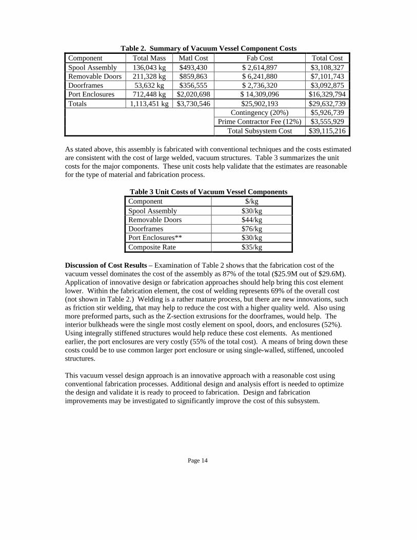
Table 2. Summary of Vacuum Vessel Component Costs Component Total Mass Matl Cost Fab Cost Total Cost Spool Assembly 136,043 kg $493,430 $ 2,614,897 $3,108,327 Removable Doors 211,328 kg $859,863 $ 6,241,880 $7,101,743 Doorframes 53,632 kg $356,555 $ 2,736,320 $3,092,875 Port Enclosures 712,448 kg $2,020,698 $ 14,309,096 $16,329,794 Totals 1,113,451 kg $3,730,546 $25,902,193 $29,632,739
Contingency (20%) $5,926,739 Prime Contractor Fee (12%) $3,555,929
Total Subsystem Cost $39,115,216 As stated above, this assembly is fabricated with conventional techniques and the costs estimated are consistent with the cost of large welded, vacuum structures. Table 3 summarizes the unit costs for the major components. These unit costs help validate that the estimates are reasonable for the type of material and fabrication process.
Table 3 Unit Costs of Vacuum Vessel Components Component $/kg Spool Assembly $30/kg Removable Doors $44/kg Doorframes $76/kg Port Enclosures** $30/kg Composite Rate $35/kg
Discussion of Cost Results – Examination of Table 2 shows that the fabrication cost of the vacuum vessel dominates the cost of the assembly as 87% of the total ($25.9M out of $29.6M). Application of innovative design or fabrication approaches should help bring this cost element lower. Within the fabrication element, the cost of welding represents 69% of the overall cost (not shown in Table 2.) Welding is a rather mature process, but there are new innovations, such as friction stir welding, that may help to reduce the cost with a higher quality weld. Also using more preformed parts, such as the Z-section extrusions for the doorframes, would help. The interior bulkheads were the single most costly element on spool, doors, and enclosures (52%). Using integrally stiffened structures would help reduce these cost elements. As mentioned earlier, the port enclosures are very costly (55% of the total cost). A means of bring down these costs could be to use common larger port enclosure or using single-walled, stiffened, uncooled structures. This vacuum vessel design approach is an innovative approach with a reasonable cost using conventional fabrication processes. Additional design and analysis effort is needed to optimize the design and validate it is ready to proceed to fabrication. Design and fabrication improvements may be investigated to significantly improve the cost of this subsystem.
Page 15
Summary A design approach has been defined for the ARIES-AT vacuum vessel for the advanced reversed-shear tokamak power plant. It will contain a high quality vacuum environment for the tokamak plasma, support the high-temperature power core, and provide supplemental thermal cooling and neutron shielding. The geometry of the design accommodates the complete sector replacement scheme. This design was assessed using conventional fabrication processes. The cost was assessed to be competitive with other conventional vacuum vessels. Several recommendations are provided for cost reduction. References
1. F. Najmabadi and the ARIES Team, "ARIES-AT reference. ,” To be published in the Journal of Fusion Engineering Design
2. L. M. Waganer, F. Najmabadi, M. Tillack, and X. Wang, “Design Approach of the
ARIES-AT Power Core”, To be published in the Journal of Fusion Engineering Design 3. L. El-Guebaly, “Nuclear Performance Assessment for ARIES-AT,” To be published in
the Journal of Fusion Engineering Design 4. L. M. Waganer, “ARIES-AT Maintenance System Definition and Analysis,” To be
published in the Journal of Fusion Engineering Design