vacuum vessel support – ongoing activity report n°1 iter vv supports... · vacuum vessel support...
TRANSCRIPT

ITER Vacuum Vessel Supports Cadarache, 21 August – 7 September 2007
Andrea Capriccioli 22/08/2007 11.45 pag. 1 of 9
Vacuum Vessel Support – ongoing activity report n°1 New Electromagnetic Forces (22 August 2007) During the downward disruptions the max load per vertical support should be close to 40 MN
(Ioki; Wang; Capriccioli meeting on 23th of August): this value includes the dead weight and the
electromagnetic horizontal forces contribution.
On the basis of this total value (40 MN) it is roughly possible to estimate the electromagnetic
vertical force: for the downward disruptions the application point of the net horizontal force (73
MN) is not clear but if an application point 3 m upper the vertical supports it’s presumed and 90°
rotated (with respect to the vertical peak position), we obtain a vertical contribution of about 6.5
MN. This means that the component due to the vertical loads only results 40-6.5 = 33.5 MN.
If the same vertical amplification factor (1.1) and the peak factor (2) are applied, we obtain as first
approximation a Total vertical force (Tvf) equal to 176 MN (⇒ 90/9 + Tvf/9 *1.1 + 2 = 33.5 MN).
Downward Plasma Disruption With reference to the Neoprene material characteristics, it’s possible to consider the following values: Neoprene transient compression limit = 80 MPa (Ref. K. Ioki) = average static pressure = 20 MPa = max static pressure ≤ 40 MPa If φ=960 mm (Ref. X.Wang) is the external bearing pad diameter, the average pressure of 80 MPa
on neoprene is reached (net φ=800mm: the average pressure results = Max local 80 MPa during
transient with =1 safety factor).
In this case we have no safety margin but other possibilities can be analyzed:
VDE Downward Forces Vertical [MN) Horizontal [MN]
176* (from 72; ratio of ≈ 2.4) (* to be checked)
73 (from 25; ratio of 3)
Asymmetry peak= 2 MN Application point=3 m* (* to be defined)
Dynamic ampl.fact.= 1.1 Dynamic ampl.fact.=1.7

Andrea Capriccioli 22/08/2007 11.45 pag. 2 of 9
the increase of the diameter from 0.8 m to 1 m: this means 36% lower pressure (see Fig1);
the use of load/stroke limiting devices to avoid neoprene damage; the use of metallic spherical joint, instead of neoprene;
the use of an upward “translated” bearing pad (see Fig.2).
Port
Bearing Pad
Pedestal Ring
1158 mm
1612 mm
Fig.1
Molybdenum Bisolfure
Fiberslip
BRONZAL (W7-X: AISI 316LN+Bronzal) INCONEL 718 (spec. ASTM B637 N07718)
ASTM-A 453
Ref. 960 mm
1800 mm
1300
mm
Fig.2
Andrea Capriccioli 22/08/2007 11.45 pag. 3 of 9
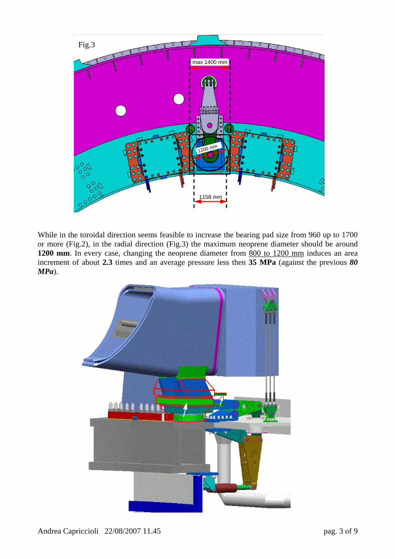
While in the toroidal direction seems feasible to increase the bearing pad size from 960 up to 1700 or more (Fig.2), in the radial direction (Fig.3) the maximum neoprene diameter should be around 1200 mm. In every case, changing the neoprene diameter from 800 to 1200 mm induces an area increment of about 2.3 times and an average pressure less then 35 MPa (against the previous 80 MPa).
1158 mm
max 1400 mm
1200 mm
Fig.3

Andrea Capriccioli 22/08/2007 11.45 pag. 4 of 9
Other open points:
• Bearing pad dimensions: lower ring (two small models show roughly the level of
stress in an example of ring). The sketch of the axial section is shown in Fig.4 and
the dimensions are set only for a preliminary analysis (see “Mageba Pot
Bearings.pdf” file as first reference)
• Vertical upward forces.
Upward Plasma Disruption
• Vertical ropes/rods/dumpers. • Radial restraint system. • Toroidal restraint system.
• Alternative solution with flexible plates as vertical (up/down) and toroidal restraint
systems.
Vertical Height ≤ 1300 mm; Toroidal Width = 960 mm; Radial Length ≤ 1400 mm.
VDE Upward Forces Vertical [MN) Horizontal [MN] __ (from 60) __ (from 25)
Asymmetry peak= 2 MN Application point=11 m
Dynamic ampl.fact.= 1.1 Dynamic ampl.fact.=1.7

Andrea Capriccioli 22/08/2007 11.45 pag. 5 of 9
Bearing Pad outer ring (half section): sketch and brief ANSYS analysis 2D analysis (ring with inner fillet 10 mm radius): Stresses in [MPa]; Displacements in [mm]
Fig.4 50
50
(D/1
5)
50
80
480[mm]
400
D=rubber diameter

Andrea Capriccioli 22/08/2007 11.45 pag. 6 of 9

Andrea Capriccioli 22/08/2007 11.45 pag. 7 of 9
3D analysis (10 mm radius inner fillet)

Andrea Capriccioli 22/08/2007 11.45 pag. 8 of 9
200
210
220
230
240
250
260
270
280
290
50 60 70 80 90 100 110 120 130 140 150 160 170 180 190
ring thickness [mm]
Max
loca
l von
Mis
es s
tres
s [M
Pa]
A brief parametric analysis to
evaluate the Max stress and
displacement, versus the ring
thickness [mm] was
performed.
After 150 mm it seems
useless to increase the ring
thichness (note: the rubber
diameter remains constat and
equal to 800 mm while the
external ring diameter
increases from 960 mm to 1320mm).
Top position ring Central position (pressure application zone) Some material properties and allowable:
AISI 316 LN Sy0.2=314 MPa (RT)
Su=540 MPa (RT)
Sm =176 MPa (RT)
Sm = 441 MPa (30 K)
ASTM-A 453 Sy0.2=589 MPa (RT)
Su=893 MPa (RT)
Sm = 295 MPa (RT)
Sm = 451 MPa (77 K)
INCONEL 718 Sy0.2=1010 MPa (RT)
Su=1246 MPa (RT)
Sm = 667 MPA (RT)
Sm = 863 MPA (77 K)
0.1
0.12
0.14
0.16
0.18
50 60 70 80 90 100 110 120 130 140 150 160 170 180 190
ring thickness [mm]
Max
radi
al d
isol
acem
ent [
mm
]

Andrea Capriccioli 22/08/2007 11.45 pag. 9 of 9
Ref.:80 mm ring thickness 100 mm
140 mm 180 mm